Embed Size (px)
Citation preview
(12) United States Patent Chen et al.
US007450598B2
US 7.450,598 B2 Nov. 11, 2008
(10) Patent No.: (45) Date of Patent:
(54)
(75)
(73)
(*)
(21)
(22)
(65)
(51)
(52) (58)
SYSTEMAND METHOD TO PROVISION MPLS/VPN NETWORK
Inventors: Wenge Chen, Pleasanton, CA (US); Holly Chen, San Ramon, CA (US); Kuo-Hui Liu, San Ramon, CA (US); Shih Chung Soon, Dublin, CA (US); Bei Zhou, Pleasanton, CA (US)
Assignee: AT&T Intellectual Property I, L.P., Reno, NV (US)
Notice: Subject to any disclaimer, the term of this patent is extended or adjusted under 35 U.S.C. 154(b) by 957 days.
Appl. No.: 10/736,445
Filed: Dec. 15, 2003
Prior Publication Data
US 2006/O182O37 A1 Aug. 17, 2006
Int. C. H04L 2/54 (2006.01) U.S. Cl. ....................................... 370/409; 370/254 Field of Classification Search ................. 370/254,
370/401, 230, 234, 223 See application file for complete search history.
2005/025 1568 A1* 1 1/2005 Zavgren, Jr. ................ 709,223 2006/0215578 A1* 9/2006 Andrapalliyalet al. ...... 370,254 2007/0226325 A1 9, 2007 Bawa et al. ................. 709,223 2007/0226630 A1* 9, 2007 Farid et al. .................. 715.734
(Continued) FOREIGN PATENT DOCUMENTS
WO WOO2 O98046 A2 * 12/2002
(Continued) OTHER PUBLICATIONS
The latest in virtual private networks: part I Metz, C.; Internet Com puting, IEEE vol. 7, Issue 1, Jan.-Feb. 2003 pp. 87-91.*
Primary Examiner Edan Orgad Assistant Examiner Salman Ahmed (74) Attorney, Agent, or Firm Toler Law Group
(57) ABSTRACT
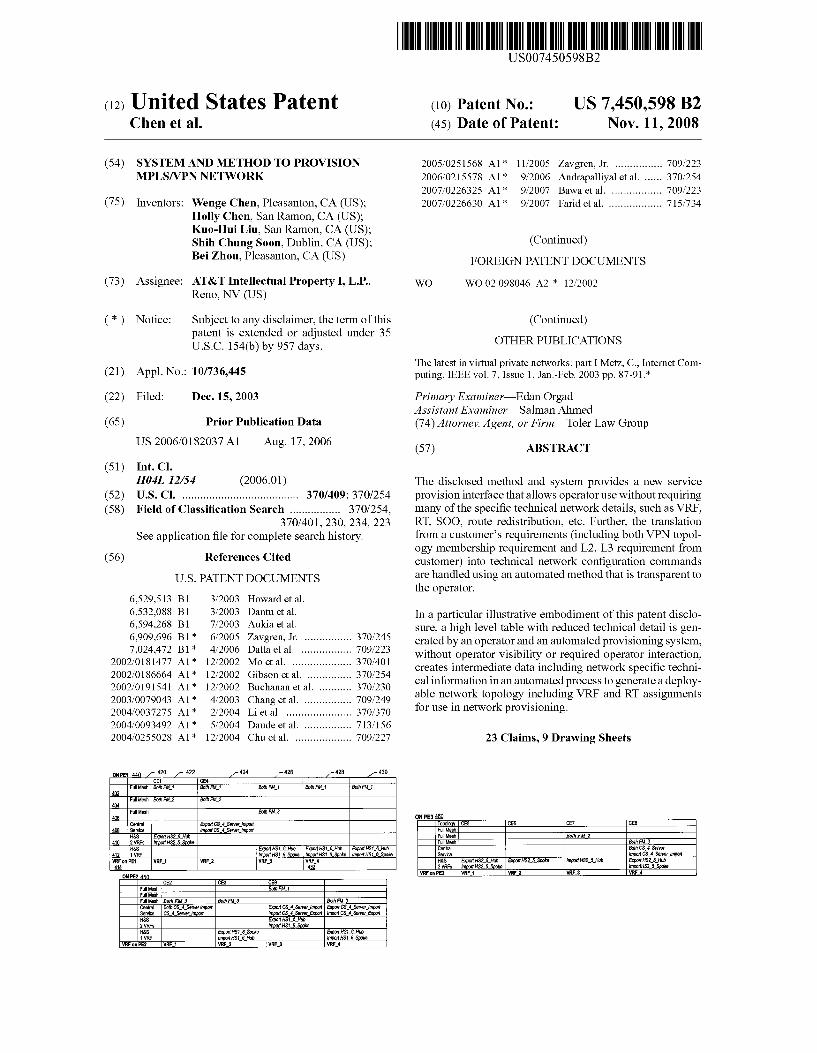
The disclosed method and system provides a new service provision interface that allows operator use without requiring many of the specific technical network details, such as VRF, RT, SOO, route redistribution, etc. Further, the translation from a customer's requirements (including both VPN topol ogy membership requirement and L2, L3 requirement from
(56) References Cited customer) into technical network configuration commands U.S. PATENT DOCUMENTS are handled using an automated method that is transparent to
the operator. 6,529,513 B1 3/2003 Howard et al.
6,532,088 B1 3, 2003 Dantu et al. In a particular illustrative embodiment of this patent disclo 6,594,268 B1 ck 7/2003 Aukia et al. sure, a high level table with reduced technical detail is gen 6,909,696 B1 ck 6/2005 Zavgren, Jr. ................ 370.245 erated by an operator and an automated provisioning system, 7,024,472 B1 4/2006 Datta et al. .. ... 709,223 without operator visibility or required operator interaction,
2002fO181477 A1* 12, 2002 MO et al. ..... ... 370, 401 creates intermediate data including network Specific techni 2002/0186664 A1* 12/2002 Gibson et al. ... ... 370,254 cal information in an automated E. tO G a deplov 2002/019 1541 A1* 12/2002 Buchanan et al. ........... 370,230 ble network topology includi p VRF i RT assi p 2003/0079043 A1* 4/2003 Chang et al. ................ TO9,249 e networ E. ogy including al asS1gnments 2004/0037275 A1* 2, 2004 Li et al. ....... ... 370/370 or use in network prov1s10ning. 2004/0093492 A1* 5, 2004 Daude et al. ................ T13,156 2004/0255028 A1* 12/2004 Chu et al. ................... 709,227 23 Claims, 9 Drawing Sheets
ONPE 440 / ? 422 424 426 428 433 CE1 CE4
FullMesh. Both F1 Both FM Both FM Both FM 1 Both FM 4
402 FullMesh Both FM2 Both FM2 404
408 FullMesh Both FM3 ONP346 Central Export CS4 Server import Topology CES CE8 cEf CE8
48 Service liport CS4 Servenpo FullMe8 H&S Esport HS25 Hub FullMe8 itFM2
0. 2WRFs import HS2.SSake FMesh Beth FM3 H&S Export HSS Hub export HS16 Hub export HS18 Hub Central Both CS4Sarver WRF import HS Spoke import HSS Spoke import RS6Spoke Service import CS Server import
WRFP wRF WRF2 WRF3 WRF4 H&S Export HS25 Hub Export HS25 Spoks inport HS25 Hui ExportHS25 Hub 414 432 2WRFs port HS25 Spoke inportHS25 Spoke
ONPE2450 WRF on P3 WRF1 WRF2 WRF3 WRF 4 CE2 CE3 CE9
FullMesh Both FM 1 FullMesh FullMesh Both FM 3 Both F3 Both F3 Central Both CS4 Server import Service CS Serve lified
Export CS Sanet import Export CS4. Serve import import CS4 Server Export importCS4Server Export
H&S Export HS15 Hub 2WRFs import HSSpoke H&S Export HS18Spoke ExportHS16 Hub WR importHS6 Hub liport HS&Spoke

US 7.450,598 B2 Page 2
U.S. PATENT DOCUMENTS WO WOO2 100.043 A1 * 12/2002 WO WO O2O995.71 * 12/2002 ck 2008/0101385 A1 5/2008 Elias et al. .................. 370/401 WO WOO3OO9528 * 1 2003
FOREIGN PATENT DOCUMENTS
WO WOO2 O995.71 A2 * 12/2002 * cited by examiner
U.S. Patent Nov. 11, 2008 Sheet 1 of 9 US 7.450,598 B2
102
TABLE1 OPERATOR INPUT TO CREATE: PART 1. WHICH CE JOINS WHAT VPNS AND THE ROLE OF THE CE IN THIS VPN PART 2. L2 AND L3 REQUIREMENT FROM CUSTOMERS PART3. INTERFACE ANDIPADDRESS, ETC. ASSIGNED BY OPERATION
AUTOMATED PROVISIONING
TABLE 2 WRF/RT TABLE 4 INTERFACE GENERATION AND ROUTING
RULES GENERATION RULES
140 TABLE 5 CL TABLE 3 COMMANDSFOR
TROUBLESHOOTING INTERFACE AND GENERATED SYSTEM WRFS AND ROUTING
ASSOCATED RTS CONFIGURATION FOR EACH VRF AND EACH CE-PE INTERFACE
EXPORT FILE122


US 7.450,598 B2 U.S. Patent

U.S. Patent Nov. 11, 2008 Sheet 6 of 9 US 7.450,598 B2
506
TERMINAL - 508
DISPLAY
INPUTIOUTPUT DEVICE
520
BACKBONE NETWORK
COMPUTER SYSTEM
MEMORY
FIG. 5

U.S. Patent Nov. 11, 2008 Sheet 7 Of 9 US 7.450,598 B2
RECEIVINGA HIGHLEVELDESCRIPTION OF A TOPOLOGY OFA 602 NETWORK
APPLYING ASET OF RULESTO THE TOPOLOGY OF THENETWORK TO 604 PRODUCE A PLURALITY OF ROUTE TARGETS ASSOCIATED WITH
VIRTUAL PRIVATE NETWORKS TO BE ASSIGNED TO THE NETWORK
GROUPING ASET OF ROUTE TARGETS FROM THE PLURALITY OF ROUTE TARGETS WITH RESPECT TO EACH CUSTOMEREQUIPMENT 606 NODE WITHIN THE NETWORK TO FORMA GROUP OF ROUTE TARGET
SETS
REMOVING DUPLICATE SETS OF ROUTE TARGETS FROM THE GROUP OF ROUTE TARGET SETS TO FORMA REDUCED SIZE SET OF ROUTE
TARGETS
ASSIGNING EACH SET OF ROUTE TARGETS IN THE REDUCED SIZE SET OF ROUTE TARGETS TO AVIRTUAL ROUTING AND FORWARDING 610 (VRF) ELEMENT WHERE ALL THE CES WITH THE SAMERT SET ON
ONE PE SHOULD SHARE ONE VRF
GENERATING ANOUTPUT FILE INCLUDING OUTPUT DATA THAT 612 IDENTIFIESEACH OF THE WRFS AND THE ASSOCIATED ROUTE
TARGETS ASSIGNED TO EACH OF THE WRFS
FIG. 6

U.S. Patent Nov. 11, 2008 Sheet 8 of 9 US 7.450,598 B2
PROVIDING ASET OF RULES REGARDING ASSIGNMENT OF ROUTE TARGETS FOREACH OF A PLURALITY OF VIRTUAL
PRIVATE NETWORKS
702
CONFIGURINGPROVIDEREQUIPMENTELEMENTS OFA 704 BACKBONE NETWORK
CONFIGURING CUSTOMEREQUIPMENTNODES, EACH OF THE CUSTOMEREQUIPMENT NODES HAVINGA
RELATIONSHIPLINK TO AT LEAST ONE OF THE PROVIDER EQUIPMENTELEMENTS
ASSIGNING ROUTE TARGETS TO EACH OF THE CUSTOMER EQUIPMENT NODES BASED ON TOPOLOGY REQUIREMENTS OF THE BACKBONE NETWORKAND BASED ON THE SET OF
RULES
CONFIGURINGEACH OF THE CUSTOMEREQUIPMENT NODES AND VRFS ON THE CORRESPONDING PROVIDER EQUIPMENTELEMENTS TO FORMALOGICAL TOPOLOGY
FIG. 7
706
708
710
U.S. Patent Nov. 11, 2008 Sheet 9 Of 9 US 7.450,598 B2
802 ADD, DELETE, ORMODIFY ASITE OF A VPN
UPDATE THE OPERATIONS INPUT TABLE TOMATCH 804 THE MODIFIED NETWORK TOPOLOGY FOR THE
UPDATED VPNS
RE-EXECUTE THE AUTOMATED PROVISIONING 806 METHOD (SEE 130 OFFIG. 1) TODETERMINEIF CHANGES TO WRFSAND/ORRTS ARENEEDED
SEND NECESSARY CL COMMANDS TO DEPLOYED 808 NETWORKEQUIPMENT TO PROVISIONNEW VPN
TOPOLOGY
FIG. 8
US 7,450,598 B2 1.
SYSTEMAND METHOD TO PROVISION MPLS/VPN NETWORK
FIELD OF THE INVENTION
The present disclosure relates generally to provisioning procedures for networks.
BACKGROUND
In connection with the deployment of high speed data communications networks, manual methods and some forms of automated provisioning software tools have been used. Some of Such provisioning tools are available for multi pro tocol label switching (MPLS) virtual private network (VPN) services.
However, these provisioning tools have some significant drawbacks. For example, operators are required to have an in-depth understanding of the technical details of the MPLS BGP/VPN technology and how to translate a customer's gen eral requirement into Such technical details. The operator is required to provide technical details and make technical deci sions, such as the specific assignment and deployment of virtual routing and forwarding (VRFs), route targets (RTs), routing redistribution, site of origin, and other similar tech nical network details.
Secondly, these approaches/tools typically require opera tors to provision each customer edge router/provider edge router (CE-PE) access individually, again requiring knowl edge of technical details, which makes the provisioning pro cess/procedures complex and error prone. The troubleshoot ing of mistakes made during this process is usually difficult and costly.
Thirdly, these approaches/tools do not provide the flexibil ity needed to easily accommodate new VPN topology and service changes. Accordingly, there is a need for an improved system and method of provisioning MPLS/VPN systems.
BRIEF DESCRIPTION OF DRAWINGS
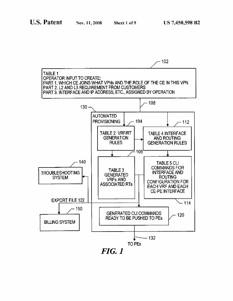
FIG. 1 is general diagram that illustrates an automated provisioning process.
FIG. 2 is a general diagram that illustrates an MPLS/VPN service provisioning table.
FIG. 3 is a general diagram that illustrates a rule set for VRF and RT mapping.
FIG. 4 is a general diagram that illustrates tables for VPN to CE mapping for various PE elements.
FIG. 5 is a block diagram to illustrate a network and com puter system that may be used to execute a provisioning process.
FIG. 6 is a flow diagram that illustrates a particular provi Sioning procedure.
FIG. 7 is a flow diagram that illustrates other aspects of a provisioning procedure.
FIG. 8 is a flow diagram that illustrates a method of provi Sioning a modified topology.
DETAILED DESCRIPTION
The present disclosure is generally directed to a method of provisioning a virtual private network and a computer net work operations system that is configured to provide Such provisioning. In a particular embodiment, the automated method of provisioning a virtual private network includes receiving a high level description of a topology of a network, applying a set of rules to the topology of the network to
10
15
25
30
35
40
45
50
55
60
65
2 produce a plurality of route targets (RTs) associated with virtual private networks to be assigned to the network, group ing a set of route targets from the plurality of route targets with respect to each customer equipment node within the network to form a group of route target sets, removing dupli cate sets of route targets from the group of route target sets to form a reduced size set of route targets; assigning each set of route targets in the reduced size set of route targets to a VRF all the CEs with the same RT set on one PE should share one VRF, and generating an output file including output data that identifies each of the VRFs and the associated route targets assigned to each of the VRFs.
In a particular embodiment, the computer network opera tions system includes a terminal having a display portion, a data input device to receive input from a user, and a computer system having a memory and a processor. The computer system is coupled to the terminal and to the data input device. The display portion of the terminal provides an input Screen having a data format configured to prompt the user to provide high-level network topology data via the data input device. The high-level network topology data includes virtual private network information with respect to a backbone data net work. The computer system converts the high-level network topology data into a set of route targets to be assigned to VRFs. The set of assigned route targets are stored in the memory.
The disclosed method and system provides a new service provision interface that allows operator use without requiring many of the specific technical network details. Further, the translation from a customer's requirements into technical network configuration commands are handled using an auto mated method that is transparent to the operator. The techni cal requirements for operators are significantly reduced allowing operators with less technical experience can be trained at a lower cost. Further, the VPN service order process to be handled more efficiently and more quickly. Also, due to automation, the number of mistakes made during the provi Sioning process is reduced.
In addition, the disclosed service provisioning method allows provisioning in an efficient manner using an overall system view instead of a link by link method. The disclosed provisioning system may consider the cost of assigning VRFs as well as access costs when determining which provideredge router (PE) a particular customer edge router (CE) is to be attached to.
Referring to FIG. 1, a flow diagram that illustrates a par ticular embodiment of a provisioning procedure is shown. The flow diagram includes a first table 102 that is formed by operator input and includes an automated provisioning sys tem 130 that includes a plurality of additional tables created by an automated software tool. The output 132 from the automated provisioning processing is a set of commands that are deployed to a network, such as to various PE nodes within an MPLS network. Data files 122 may be exported from the automated provisioning system 130 and sent to other systems, such as a troubleshooting system 140 or a billing system 150. The data files 122 provided by the provisioning system 130 are often useful to technical Support personnel in resolving technical problems reported by customers, such as issues relating to network configurations and performance. Also, the billing system 150 may use input from the exported file 122 to add new billing parameters and to charge for use of network resources, such as charges based on the number of virtual routing and forwarding elements (VRFs) used by a particular VPN topology. Thus, the cost of assigning VRFs may be considered in the bills sent to customers.

US 7,450,598 B2 3
The operator inputted table 102 includes a first part that includes data to identify customer edge router (CE) and asso ciated VPNs. A second part of the table 102 identifies layer 2 and layer 3 network requirements received from customers. The third part of the operatortable 102 includes interfaces and IP address assignments. A resulting data table 108 is provided to the automated provisioning system 130. Within the provi sioning system 130 a set of, VRF/RT rules 104 are used to generate a table 106 that includes assigned VRFs and RTs. Also, a table 112 having interface and routing generation rules is used to create CLI commands, such as in table 114, for each VRF and each associated CE-PE interface. The outputs from the generated VRFs and RTs and the CLI commands are communicated to a module 120 to generate CLI commands for the CEs and prepare data to be communicated to PEs. The resulting data output 132 is then deployed to PEs to deploy the provisioned topology in the network. An example of a VRF is found within a commercial router, such as those made by Cisco, Inc., that are deployed in distributed data communica tion networks.
Referring to FIG. 2, an example of the operator inputted table 102 is illustrated. The table 102 includes a first portion 202, a second portion 204, and a third portion 206. The first portion 202 includes VPN to CE mapping and topology selec tion or each VPN. The second portion 204 identifies the layer 2 and layer 3 network requirements and CE locations. The third portion 206 identifies IP interface on PE and IP address and quality of service (QoS) requirements and profiles. Cus tomer information is also included in table 102, such as the customer A and customer B in the first row; CE1-CE11 belong to customer A and CE12-CE13 belong to Customer B.
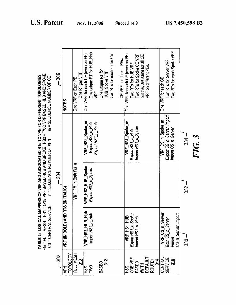
Referring to FIG. 3, a logical mapping table of VRFs and associated RTS is shown. The logical mapping table includes row entries of full mesh 310, hub and spoke with two VRFs 312, hub and spoke with one VRF 314, and a central service row 316. The column entries include the assigned RTs and VRFs 330, 332, 334, and a comments column 306.
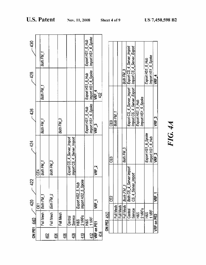
Referring to FIG. 4, VRF and RT mapping tables 440, 450, and 460 for multiple PEs are shown. A first table 540 for PE1 includes a plurality of VPN row elements 402-412, a VRF indicator row 414, and a plurality of CE columns 422-430. The table 440 also includes a topology indication column 420. As shown, one of the VRFs, VRF 4 labeled 432 is shared by two CEs, CE12 in column 428 and CE13 in column 430. By providing for a shared VRF, the number of used VRFs for the desired VPN topology is beneficially reduced and for a large network provides for reduced VRF deployment costs. Thus, the resulting set of VRFs is a reduced size set. In accordance with the VRF generation rules, RTs are assigned for each CE based on its topology requirement in Table 1 and the RT generation rules in Table 2. If multiple CEs share the same RT set, such as the last CE12 and CE13, then they share one VRF. Generally, each VRF owns all the RTs in its column, However, all the CE members of one full mesh VPN belong to another full mesh VPN, which means that one VPN is the subset of another VPN. Therefore, the corresponding VRF may not need the RT of the subset VPN if it makes no differ ence to the customers.
Dualhoming requirement can also be handled with respect to Table 1. There are 3 common scenarios for dualhoming:
1. Two CES connecting to two PE by two physical or logical links. This scenario can be handled by Table 1 natively.
2. One CE connecting to two PE by two physical or logical links. Two columns for each CE are used. Part 1 for these two columns are the same. There may be the same or different L2 or L3 requirement in part 2, one IP interface and IP address/mask on each PE in part 3.
10
15
25
30
35
40
45
50
55
60
65
4 3. One CE connecting to one PE by two parallel physical
links or logical links. Two columns for each CE are used. Part 1 for these two columns are the same. There may be the same or different L2 or L3 requirement in part 2, operation needs to assign two IP interfaces and two IP addresses/masks on the PE.
The “Site” concept in industry standard RFC2547bis can also be easily integrated into Table 1 by adding a row named “Site” in Table 1 which tells which site each CE belong to. If a customer wants the traffic between two or more CEs go through its private network only, which means that customer does not rely on the SP network as both primary and backup connection for these CEs, these CEs should be assigned to one site. The same SOO (Site of Origin) should be configured for the CE-PE interfaces on PEs to avoid routing loop if EBGP is used as the CE-PE routing protocol.
Referring to FIG. 5, a sample operations system for imple menting the disclosed provisioning procedure is shown. The operations system includes a computer system 502 with a memory 504. The computer system 502 is coupled to a back bone network 520, such as a MPLS network. The computer system 502 has an input/output device 510 and a terminal 506 with a display 508 used to interface to network operations personnel. Computer Software that can receive an operator input table and can perform automated provisioning proce dures to deploy VRF and RT assignments for network ele ments within the backbone network 520 can be disposed in the memory 504 and executed by the computer system 502. An example of a suitable computer system 502 is a commer cially available personal computer or workstation.
Referring to FIG. 6, a particular embodiment of a method of provisioning a network is illustrated. A high level descrip tion of a network topology, such as the table 102 of FIG. 1, is received, at 602. A set of provisioning rules is applied to the topology of the network to produce a plurality of route targets (RTs) associated with virtual private networks to be assigned to the network, at 604. A set of route targets from the plurality of route targets is grouped with respect to each customer edge router (CE) within the network to form a group of route target sets, at 606. Duplicate sets of route targets are removed from the group of route targets to form a reduced size set of route targets, at 608. Each set of route targets in the reduced size set of route targets is assigned to a virtual routing and forwarding (VRF) element all the CEs with the same RT set on one PE should share one VRF, at 610. By reducing the number of route targets and by sharing VRFs, less network resources are consumed by the desired network topology. An output file is generated, at 612, that includes output data that identifies each of the VRFs and the associated route targets assigned to each of the VRFs. The output file may be deployed to physical network equipment to complete the provisioning process.
Referring to FIG. 7, another particular embodiment of a method of provisioning is illustrated. A set of rules is pro vided regarding assignment of route targets for each of a plurality of virtual private networks, at 702. Provider edge routers (PE) of a backbone network are configured, at 704. Customer edge routers (CE) are configured, at 706. Each of the CE nodes has a relationship link to at least one of the PE elements. Route targets are assigned to each of the CE nodes based on topology requirements of the backbone network and based on the set of rules, at 708. An example of the set of rules is the table of rules illustrated in FIG.3. Each of the CE nodes and VRFs are configured with respect to the corresponding PE elements to form a logical network topology, at 710. The logical topology may be converted into an output file that is deployed in physical router equipment, to thereby provision Such equipment.
US 7,450,598 B2 5
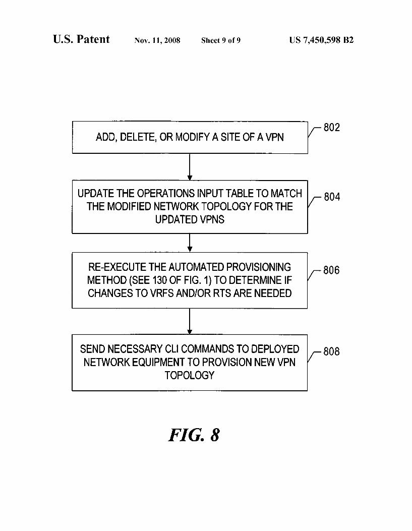
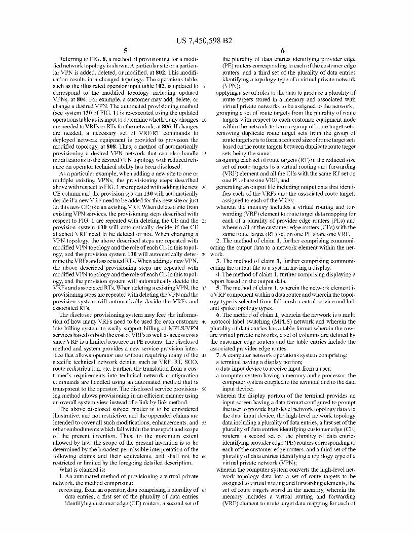
Referring to FIG. 8, a method of provisioning for a modi fied network topology is shown. A particular site or a particu lar VPN is added, deleted, or modified, at 802. This modifi cation results in a changed topology. The operations table, such as the illustrated operator input table 102, is updated to correspond to the modified topology including updated VPNs, at 804. For example, a customer may add, delete, or change a desired VPN. The automated provisioning method (see system 130 of FIG. 1) is re-executed using the updated operations table as its input to determine whether any changes are needed to VRFs or RTs for the network, at 806. If changes are needed, a necessary set of VRF/RT commands to deployed network equipment is provided to provision the modified topology, at 808. Thus, a method of automatically provisioning a desired VPN network that can also handle modifications to the desired VPN topology with reduced reli ance on operator technical ability has been disclosed. As a particular example, when adding a new site to one or
multiple existing VPNs, the provisioning steps described above with respect to FIG. 1 are repeated with adding the new CE column and the provision system 130 will automatically decide if a new VRF need to be added for this new site or just let this new CE join an existing VRF. When delete a site from existing VPN services, the provisioning steps described with respect to FIG. 1 are repeated with deleting the CE and the provision system 130 will automatically decide if the CE attached VRF need to be deleted or not. When changing a VPN topology, the above described steps are repeated with modified VPN topology and the role of each CE in this topol ogy, and the provision system 130 will automatically deter mine the VRFs and associated RTs. When adding a new VPN, the above described provisioning steps are repeated with modified VPN topology and the role of each CE in this topol ogy, and the provision system will automatically decide the VRFs and associated RTs. When deleting a existing VPN, the provisioning steps are repeated with deleting the VPN and the provision system will automatically decide the VRFs and associated RTs. The disclosed provisioning system may feed the informa
tion of how many VRFs need to be used for each customer into billing system to easily support billing of MPLS/VPN services based on both the cost of VRFs as well as access costs since VRF is a limited resource in PE routers. The disclosed method and system provides a new service provision inter face that allows operator use without requiring many of the specific technical network details, such as VRF, RT, SOO. route redistribution, etc. Further, the translation from a cus tomer's requirements into technical network configuration commands are handled using an automated method that is transparent to the operator. The disclosed service provision ing method allows provisioning in an efficient manner using an overall system view instead of a link by link method. The above disclosed subject matter is to be considered
illustrative, and not restrictive, and the appended claims are intended to cover all Such modifications, enhancements, and other embodiments which fall within the true spirit and scope of the present invention. Thus, to the maximum extent allowed by law, the scope of the present invention is to be determined by the broadest permissible interpretation of the following claims and their equivalents, and shall not be restricted or limited by the foregoing detailed description. What is claimed is: 1. An automated method of provisioning a virtual private
network, the method comprising: receiving, from an operator, data comprising a plurality of
data entries, a first set of the plurality of data entries identifying customer edge (CE) routers, a second set of
5
10
15
25
30
35
40
45
50
55
60
65
6 the plurality of data entries identifying provider edge (PE) routers corresponding to each of the customer edge routers, and a third set of the plurality of data entries identifying a topology type of a virtual private network (VPN);
applying a set of rules to the data to produce a plurality of route targets stored in a memory and associated with virtual private networks to be assigned to the network;
grouping a set of route targets from the plurality of route targets with respect to each customer equipment node within the network to form a group of route target sets;
removing duplicate route target sets from the group of route target sets to forma reduced size of route target sets based on the route targets between duplicate route target sets being the same;
assigning each set of route targets (RT) in the reduced size set of route targets to a virtual routing and forwarding (VRF) element and all the CEs with the same RT set on one PE share one VRF; and
generating an output file including output data that identi fies each of the VRFs and the associated route targets assigned to each of the VRFs;
wherein the memory includes a virtual routing and for warding (VRF) element to route target data mapping for each of a plurality of provider edge routers (PEs) and wherein all of the customer edge routers (CEs) with the same route target (RT) set on one PE share one VRF.
2. The method of claim 1, further comprising communi cating the output data to a network element within the net work.
3. The method of claim 1, further comprising communi cating the output file to a system having a display.
4. The method of claim 1, further comprising displaying a report based on the output data.
5. The method of claim 1, wherein the network element is aVRF component within a data router and wherein the topol ogy type is selected from full mesh, central service and hub and spoke topology types.
6. The method of claim 1, wherein the network is a multi protocol label switching (MPLS) network and wherein the plurality of data entries has a table format wherein the rows are virtual private networks, a set of columns are defined by the customer edge routers and the table entries include the associated provider edge routes.
7. A computer network operations system comprising: a terminal having a display portion; a data input device to receive input from a user; a computer system having a memory and a processor, the
computer system coupled to the terminal and to the data input device;
wherein the display portion of the terminal provides an input Screen having a data format configured to prompt the user to provide high-level network topology data via the data input device, the high-level network topology data including a plurality of data entries, a first set of the plurality of data entries identifying customer edge (CE) routers, a second set of the plurality of data entries identifying provider edge (PE) routers corresponding to each of the customer edge routers, and a third set of the plurality of data entries identifying a topology type of a virtual private network (VPN);
wherein the computer system converts the high-level net work topology data into a set of route targets to be assigned to virtual routing and forwarding elements, the set of route targets stored in the memory, wherein the memory includes a virtual routing and forwarding (VRF) element to route target data mapping for each of

US 7,450,598 B2 7
a plurality of provideredge routers (PEs) and wherein all of the customer edge routers (CEs) with the same route target (RT) set on one PE share one VRF.
8. The computer network operations system of claim 7. wherein the backbone data network comprises a multi proto collabel switching (MPLS) network.
9. A method of provisioning a virtual private network ser vice, the method comprising:
providing a set of rules regarding assignment of route tar gets stored in a memory for each of a plurality of virtual private networks;
configuring provider edge routers (PEs) of a backbone network;
configuring customer edge routers (CES), each of the cus tomer edge routers having a relationship link to at least one of the provider edge routers;
assigning route targets to each of the customer edge routers based on topology requirements of the backbone net work and based on the set of rules, wherein route targets are grouped into sets and duplicate sets of route targets are removed based on the route targets between dupli cate sets of route targets being the same, and wherein the topology requirements comprise a plurality of data entries, a first set of the plurality of data entries identi fying customer edge (CE) routers, a second set of the plurality of data entries identifying provider edge (PE) routers corresponding to each of the customer edge rout ers, and a third set of the plurality of data entries identi fying a topology type of a virtual private network (VPN); and
configuring each of the VRFs and RTs on the correspond ing provider edge routers to form a logical topology;
wherein the memory further includes a virtual routing and forwarding (VRF) element to route target data mapping for each of a plurality of provideredge routers (PEs) and wherein all of the customer edge routers (CEs) with the same route target (RT) set on one PE share one VRF.
10. The method of claim 9, further comprising adding an additional CE to one of the plurality of virtual private net works to form a modified logical topology.
11. The method of claim 10, wherein the modified logical topology has a new VPN with respect to the logical topology.
12. The method of claim 9, further comprising deleting one of the CEs of one of the plurality of virtual private networks to form a modified logical topology.
13. The method of claim 12, wherein the modified logical topology has a removed VPN with respect to the logical topology.
14. The method of claim 9, further comprising communi cating the logical topology to a remote computer system wherein the logical topology includes a modified topology type, the modified topology type changed from Hub and Spoke to a full mesh arrangement.
15. The method of claim 14, further comprising displaying a graphical representation of the logical topology to a user of a terminal coupled to the computer system.
10
15
25
30
35
40
45
50
55
8 16. The method of claim 15, wherein the terminal is an
operations terminal of a network management system, the network management system tied to the backbone network.
17. The method of claim 9, wherein the network element is aVRF component within a data router and wherein the topol ogy type is selected from full mesh, central service and hub and spoke topology types.
18. The method of claim 9, wherein the network is a MPLS network and wherein the plurality of data entries has a table format wherein the rows are virtual private networks, a col umn includes the network topology type, a set of columns are defined by the CEs and the table entries include the associated PES.
19. A system to monitor a backbone network, the system comprising:
a terminal having a display portion; a data input device to receive input from a user; a computer system having a memory and a processor, the
computer system coupled to the terminal and to the data input device;
wherein the display portion of the terminal provides an input Screen having a data format configured to prompt the user to provide high-level network topology data via the data input device, the backbone network including a plurality of CEs, a plurality of PEs, a plurality of virtual routing and forwarding components, a plurality of route targets, a plurality of virtual private networks and wherein the high level network topology data identifies the CEs, the PEs within each of the virtual private net works, and a plurality of data entries, a first set of the plurality of data entries identifying customer edge (CE) routers, a second set of the plurality of data entries identifying provider edge (PE) routers corresponding to each of the customer edge routers, and a third set of the plurality of data entries identifying a topology type of a virtual private network (VPN);
wherein the computer system includes a set of rules to convert the high-level network topology data into a set of route targets to be assigned to virtual routing and for warding (VRF) elements, the set of route targets stored in the memory; and
wherein the memory further includes a VRF to route target data mapping for each of a plurality of PEs and wherein the CES with the same RT set on one PE share one VRF.
20. The system of claim 19, wherein the set of rules includes a first set of rules to handle route target to VRF mapping based on a meshed topology and a second set of rules to handle route targets to VRF mapping for a hub and spoke topology and a third set of rules to handle route targets to VRF mapping for a central service topology.
21. The system of claim 20, wherein the second set of rules includes an import rule and an export rule.
22. The system of claim 21, wherein the second set of rules applies to two route targets for a particular VRF component.
23. The system of claim 19, wherein the memory further stores a Software program to generate and deploy the set of route targets into a physical network router node.
k k k k k