Embed Size (px)
Citation preview

UNITED STATES DEPARTMENT OF THE INTERIOR
BUREAU OF RECLAMATION
HYDRAULIC MODEL STUDIES TO DEVELOP A SEDIMENT CONTROL ARRANGEMENT FOR ANGOSTURA DIVERSION--MIDDLE RIO GRANDE
PROJECT, NEW MEXICO
Hydraulic Laboratory Report No. Hyd-419
DIVISION OF ENGINEERING LABORATORIES
COMMISSIONER'S OFFICE DENVER, COLORADO
February 21, 1957
--

FOREWORD
The hydraulic model studies reported herein were cond~cted in the Hydraulic Laboratory, Commissioner's Office, Bureau of Reclamation, Denver, Colorado, during the period January through July 1956.
The designs and studies were made in cooperation with the Canals and Head.works Section, Canals Branch. Messrs. A. w. Kidder, H. E. White, J. A. Hufferd, and R. D. Ridinger of the Canals Branch visited the laboratory on numerous occasions and made many help:f'ul suggestions.
The studies were made by T. J. Rhone and G. R. Iogan under the supervision of E. J. Carlson.

CONTENTS
Summary • • • • • • • • • • • • • • • • • • • • •. • • • • • . • .• • Introduction • • • • • • • • • • • • • • • • • • • • • • • • . • • Th.e Model • • • • ., • • • • • • • • • • • • • • • • • • • • •. , • Method of Operation • • • • • • • • • • • • • • • • • • • • .• • • Th.e Investigation • • • • • • • • • • • • • • • • • • • • • • • •
Preliminary Design, Test No. 1 • • • • • · • • • • • • • Overhanging Sill or Corbel, Test No. 2 • • • . • • • • • Zigzag Overhanging Sill, Test No. 3 ••••••••• Zigzag Overhanging Sill and Curved Approach Channel,
Test No. 4 • • • . • • • • • • • . • • • • . . • ••
• • • • ..... . •·. . . • • • •
Vertical Wall at Head.works Entrance, Test No. 5 ••••••• Overhanging Sill, Narrow Sluiceway, Test No. 6 •••••••• Approach Channel 4o-feet Wide, Test No. 7 •••••••••• Right Half of Sluiceway Closed, Test No. 8 •••••••••• Flow Through Three Bays, Test No. 9 ••••••••••••• Vortex Tubes, Tests No. 10 and 11 •••••••••••••• Approach Channel 30-feet Wide, Test No. 12 ••••••••••
-· l ·.2
3 4
·5
5 5 5
6 6 7 7 7 8 8 9
Recommended Modification, Test No. 13. • • • • • • • • • • • • • 10
Head Loss •••• Sand Bed Movement
• • • • • • • • • • • • • •
• • • •
• • • • • • • • • • • • • •
. . ... • • • •
• • • •
Location Map • • • • • • • • • • • • • • • • • • • • • • • • • • Prototype Layout • • • • • • • • • • • • • • • • • • • • • • • • Model Drawing ·• • • • • • • • • • • • • • • • • • • • • • • • • • Preliminary Design • • • • • • • • • • • • • • • • • • • • • • • Sand Bed After Test No. 1 • • • • • • • • • • • • • • • • • • • • Overhanging Sill or Corbel ••••••••••••••••••• Overhanging Sill in Zigzag Pattern ••••••••••••••• Sand Bed After Test No. 2 • • • • • • • • • • • • • • • • • • • • Curved Approach Channel ••••••••••••••••••••• Sand Bed After Test No. 4 • • • • • • • • • • • • • • • • • • • • Vertical Wall at Turnout Entrances ••••••••••••••• Sand Bed After Test No: 5 • • • • • • • • • • • • • • • • • • • • Overhanging Sill, Narrow Sluicewa.y • • • • • • • • • • • • • • • Sand Bed After Test No. 6 • • • • • • • • • • • • • • • • • • • • Approach Channel 4o-feet Wide • • • • • • • • • • • • • • • • • • Sand Bed After Test No. 7 • • • • • • • • • • • • • • • • • • • • Right Half of Sluiceway C~osed •••••••••••••••••
12 12
Figure
1 2 3 4 5 6A 6B 7 8 9
10 11 12 13 14 15 16

C0NTENTS--Continued
Sand Bed After Te st No • 8 • • • • • • • • • • • • • • • • • • • • Sand Bed After Test No. 9 • • • • •. • • • • • • • • • • • • • • • Vortex Tubes • • • • • • • • • • • • • • • • • • • • • • • • • • Sand Bed After Tests No. 10 and 11 ••••••••••••••• Approach Channel 30-feet Wide •••••••••••••••••• Sand Bed After Test No. 12 ••••••••••••••••••• Recommended Design, Test No. 13 ••••••••••••••••• Sand Bed After Test No. 13 • • • • • • • • • • • • • • • • • • • Sand Bed Profiles • • • • • • • • • • • • • • • • • • • • • • • •
11
Figure
17 18 19 20 21 22 23 24 25

UIIBD STABS DEPAR'l'MD'l' OF mE nm:RIQR
BUREAU OF RECLAMA'fi01f
Commissioner's otf'ice--Denver Division of Engineering Laboratories Bydraulic Laboratory Branch Bydraulic Investigations Section Denver, Colorado February 21, 1.957
Laboratoey Report Ko. iJd-419 Caapiled by: 'l'. J. Rhpne Checked by: E. J. Carlson Reviewed by: C. W. Thomas Submitted by: H. M. Martin
HYDRAULIC MODEL STUDIES TO DEVELOP A SEDIMENT CONTROL ARRANGEMENT FOR ANGOSTURA DIVERSION--MIDDLE
RIO GRANDE PROJECT, NEW MEXICO
The model studies were conducted to determine a method of reducing the amount of bedload sediment that was entering the headworks of Albuquerque Main Canal.
Initial tests, made to duplicate the prototype action and to set a basis tor comparing the effectiveness of all modifications, showed that a ratio of the concentration of sediment in the flow through the river aluiceway to the concentration of sediment in the headworks flow was 0.17. Addition of an overhanging sill 1B front of the headworks entrance, Figure 6A, increased this ratio to 0.87. A curved approach channel 48-1/2 feet wide used in conjunction with the overbanging sill, Figure 12, incre.ased the ratio to 2.62.
Further tests were made to determine the most effective width for the curved approach channel and the effectiveness of using a vortex tube in front of the last bay. The tests showed that it was possible with a .combination of a narrow curved approach channel, overhanging sill, and vortex tube to increase the sediment concentration ratio to '11-54· However, in order to present modifications that were more practical. to construct, a design was recommended, Figure 23, that resulted in a sediment concentration ratio of 41.08 when the vortex tube was in operation and 5.42 when the vortex tube was closed.
other recommendations ~volved from the model study are:
(l) Whenever water is being diverted into the canal, the gates in all tour bays of the headvorks should be opened equally.

(2) The river sluiceway should be open to pass water at all times and whenever possible the quantity should not be less than 150 cfs.
(3) In the recommended modifications, Figure 23, the width of the river sluiceway has been reduced by one-half. Although no tests were made with two sluice gates, it is reconmended that radial gates be . :furnished for both sides of the sluiceway so that the 011tside section can be opened to remove sediment deposits between the existing guide wall and the new guide wall.
(4) The sluice gates should be left open during the receding part of a fl.ood to prevent sediment depositing in the cbarmel between the guide walls.
(5) Due to the small available head, if a vortex tube is used, fl.ow through the tu'be should be induced by means of a sediment pump capable of pumping 20 cfs against 15 feet of head.
(6) The sediment pump sh011ld be in operation whenever water is being diverted through the headworks and also at regular intervals when water is not being diverted in order to clear the vortex tube of uy sediment that might settle from the suspended load.
DTROWCTION
The Angostura Diversion Works is located on the Rio Grande 20 miles northeast of Albuquerque, Rew Mexico, Figure l.
The diversion works consist of a low diversion dam across the river, a head.works structure that diverts water into the Albuquerque Main Canal and a river sluicevay between the headworks and the diversion dam, Figure 2.
The structure bas been in operation several years and in that time the sedimentation problem bas become quite acute. A settling channel downstream. from the headworks bas become practical.17 useless because of heavy sediment deposits. Sediment already removed from this channel has been piled on both banks and the available storage space bas diminished to sucll an extent that in the :future it will become increasingly difficult to store sediment tram the channel.
The uvestigations described in this report were concerned with reducing the amount of bed.load sediment entering tbe diversion works.
2

TIE MODEL
Tbe model vaa constiucted to a scale ot 1 to 10 and included the turnout structure or headworks, the river alaiceva7, aa4 a small area ot the Rio Grand.e, Figure 3. All of the structures of the 4iveraion works were reproduced 1n wood with the exception of radial gates 1n the headvorlta and sluicewa7 which were constructed f'r011 gal'V&Dized sheet metal.
'.rwo tn,es of sand were available which COlild be used to represent the prototype river sand. These were a white silica sand with a mean diameter of 0.2 DD with 90 percent between the Bo. 4o and Bo. 200 Tyler Standard Screens; the second was a coarser sand c0111110D17 used 1n the laboratory with a median diameter of approximately o.8_mm with 90 percent between the Bo. 8 and Bo. 200 Tyler Standard -Screens. The laboratory s&Dds were compared to the prototype sediment on the basis of.fall velocity. A. representative sample of the bed.load sediment that had been removed from the headworks settling basin vaa used tor the comparison. The fall velocity of this material was reduced by the square root of the model scale and. this curve coapared to the tall velocity- curves of the two types of laboratory sand. Since the investigation was concerned. with the bedload, it vas decided that the coarser laboratory aaad slllould. be used to represent the prototype sediment.
Water was suppl.ied to the model from the l.abor&torJ" suppl7 cbamie.l thrO\lgh a portable pmp and :measured by an orifice venturi meter. The q11aatit7 of fl.ow through the river sluiceway- was determined by a calibrated slide gate placed downstream from the sluiceway radial gate. The slide gate also served to provide a backwater downstream traa the radial gate to simulate the prototype cond.itims. i'he quantity of flow through the headwork.s was determined b;y subtracting the sluicewa7 discharge from the total inflow.
The sand tut passed through the head.works and river sluiceway was carried downstream to a sand trap and trca there- recirculated to the upstrea encl of the head box b7 a small sand pma.p, Figure 3, thus there was al1f&78 a constant supply of sand entering the flow upstream tram tla.e diversion works. The flow through the sand punp ·was measured 'by a 2-inch venttari meter.
Water surface elevations were determined from staff gage& placed at critical points.
Sediment con~entrations in the flow throggh the headworka and river sluieewa7 were obtained as one method of detel'llin1Dg the effectiveness ot various alterations. The concentratiou were determined by
3

passing a collecting trough through the nappe of the flow from the sluiceway and headworks. These samples were collected in tanks calibrated to read the volume in liters. The sediment in the sample settled to the bottom of the tank into a removable glass funnel. The sand was removed from the funnel and poured into calibrated glass cones from which the amount of sand in grams could be read directly and the concentration computed without further conversion of the data.
M.F:l'HOD OF OPERATION
In order to :maintain uniform conditions so that all modifications could be judged on the same basis and to reduce the number of variables and simplify the testing, the following conditions were maintained for all tests unless otherwise noted:
(1) Only one discharge was used for all tests. This was 650 cfs with 500 cfs diverted into the headworks and 150 cfs through the river sluiceway.
(2) The water surface elevation was maintained at elevation 5o84.25 as measured on a staff gage placed on the left wall Just upstream from the sluiceway radial gate.
(3) The radial gates in all four bays of the headworks were op;:,ned equally.
(4) The quantity of flow through the river sluiceway was regulated by the slide gate downstream from the radial gate, however, the radial gate was closed sufficiently to induce approximately a 1/2-foot head loss across the gate in order to duplicate the prototype condition.
Generally speaking, all model modifications were tested in the following manner. After a modification had been installed, the sand bed upstream from the structure was leveled. A discharge representing 650 cfs was turned into the model; as soon as the box was filled, the river sluiceway gate was opened sufficiently to pass a discharge of 150 cfs. The gates of the head.works structure were then equally opened so th&t the remaining flow would pass through them. and maintain the water surface elevation in front of the sluiceway at elevation 5084.25. The sand pump was next turned on in order to insure a resupply of sediment. Care was taken at all times to insure that the combined flow of the two pumps did not exceed 650 cfs and that the water surface elevation remained constant.
4

The model was operated under these conditions tor a period of between 12 to 24 hours in order to establish an equilibrium condition in the sand bed movement. After a· state of equilibrium was attained., sand-water samples were-taken at 15-minute intervals tor the next 5 to 7 hours. The average of the sediment concentration in these samples was used to compute a ratio, Cs/Ca, between the sand concentration in the sluiceway flow and the sand concentration in the head.works flow. This ratio was used as a measure ot the effectiveness ot a modification in excluding sediment from the turnout or head.works structure.
THE INVESTIGATION
Preliminary Design, Test No. 1
. The initial test was made with the preliminary or existing design installed, Figure 4. This test was the l.ongest in duration of the series and extended tor.55 hours. After the first 23 hours, sediment concentration samples were taken at intervals for the next 8 hours. After an additional 16-hour run, sediment concentration samples were again obtained over an 8-hour period. This proportion of sampling periods to running time was maintained for the duration of the test.
The average sediment concentration ratio for this test was Cs/Cu = 0.17. The appearance of the sand bed in front of the turnouts after this test is shown in Figure 5.
Overhanging Sill or Corbel, Test No. 2
For the first modification an overhanging sill or corbel. was placed in front of all four bays of the entrance of the turnout structure, Figure 6A.. The principle of the sill was that the sharp leading edge and the sloped undersurface of the overhang would induce secondary currents and eddies that would move the bedl.oad away from the turnout entrance and on downstream toward the sluiceway.
The overhanging sill was an improvement over the preliminary design. The test was run for 48-1/2 hours and sediment cqncentration samples were obtained at intervals during the 24th to 31st hours· and during the final 2 hours of operation. The average sediment concentration ratio for this test was Cs/C:H • O .87. The appearance ot the sand bed after this test is-shown on Figure 7.
Zigzag Overhanging Sill, Test No. 3
For this test the same sill was used but instead of being placed in a straight line in front of the turnout it was pl.aced in a
5

zigzag pattern, Figure 6B. It was thought that the zigzag effect would induce more secondary currents and eddies and result in a more efficient sediment exclusion. However, after a comparatively short run it became apparent from visual observations that this setup was not an improvement over the previous modification and the test was discontinued.
Zigzag Overhanging Sill and Curved Approach Channel, Test No. 4
For this test the overhanging sill placed in a zigzag pattern was not removed. In addition to the sill, parallel walls 48-1/2 feet apart were placed upstream from the head.works so that they formed a curved approach channel leading to the headworks, Figure 8. The tops of the walls were at elevation 5086. The principle involved was that when the flow was guided by the walls the curvature would keep the larger portion of the sediment on the inside of the curve and away from the head.works entrance. Investigations have been performed in the laboratory using curved walls to control sediment deposition and they were found to be very effective.*
This test was run for 21-1/2 hours and sediment concentration samples obtained during the final 2-1/2 hours. The curved approach channel was a great improvement over the previous tests as shown by the average ratio Cs/CH = 2.64. The appearance of the sand bed after this test is shown on Figure 9.
Vertical Wall at Head.works Entrance, Test No. 5
The designers felt that an overhanging sill would involve an expensive construction outlay, especially if it were to be placed in a zigzag pattern. It had already been demonstrated that the zigzag pattern did not materially increase the sediment exclusion features of the overhanging sill. Therefore, this test was run to determine whether an overhanging sill was necessary or whether a vertical wall served the
*Hydraulic Laboratory Report No. Hyd-275 ''Hydraulic Model Studies of Superior-Courtland Diversion Dam, Headworks, and Sluiceway Structures--Progress Report No. 1 on General Studies of Head.works and Sluiceway Structures."
Hydraulic Laboratory Report No. Hyd-316 "Hydraulic Model Studies of Republic Diversion Dam, Headworks and Sluiceway Structures-Progress Report No. 2 on General Studies of Headworks and Sluiceway Studies."
Hydraulic Laboratory Report No. Hyd-384 "Hydraulic Model Studies of Bartley Diversion Dam--Progress Report No. 3 on General Studies of Headworks and Sluiceway Structures, Missouri River Basin Project, Nebraska."
6

purpose. For this modification the overhanging sill was replaced with a vertical wall set in front of all four bays of the turnout structure. The top of the vertical wall was at the same elevation as the tip of the overhanging sill. The 48-1/2-foot-wide curved approach channel was also included as a part of this modification, Figure 10.
Thia test was run·for 31 hours and sediment concentration samples were obtained during the final 7 hours. The average sediment concentration ratio during this test was Cs/Ca: • O.EiB. This was a considerable decrease from the previous tests indicating that the· overhanging sill was important in obtaining good sediment exclusion.
Figure ll shows the sand bed at the conclusion of.this test.
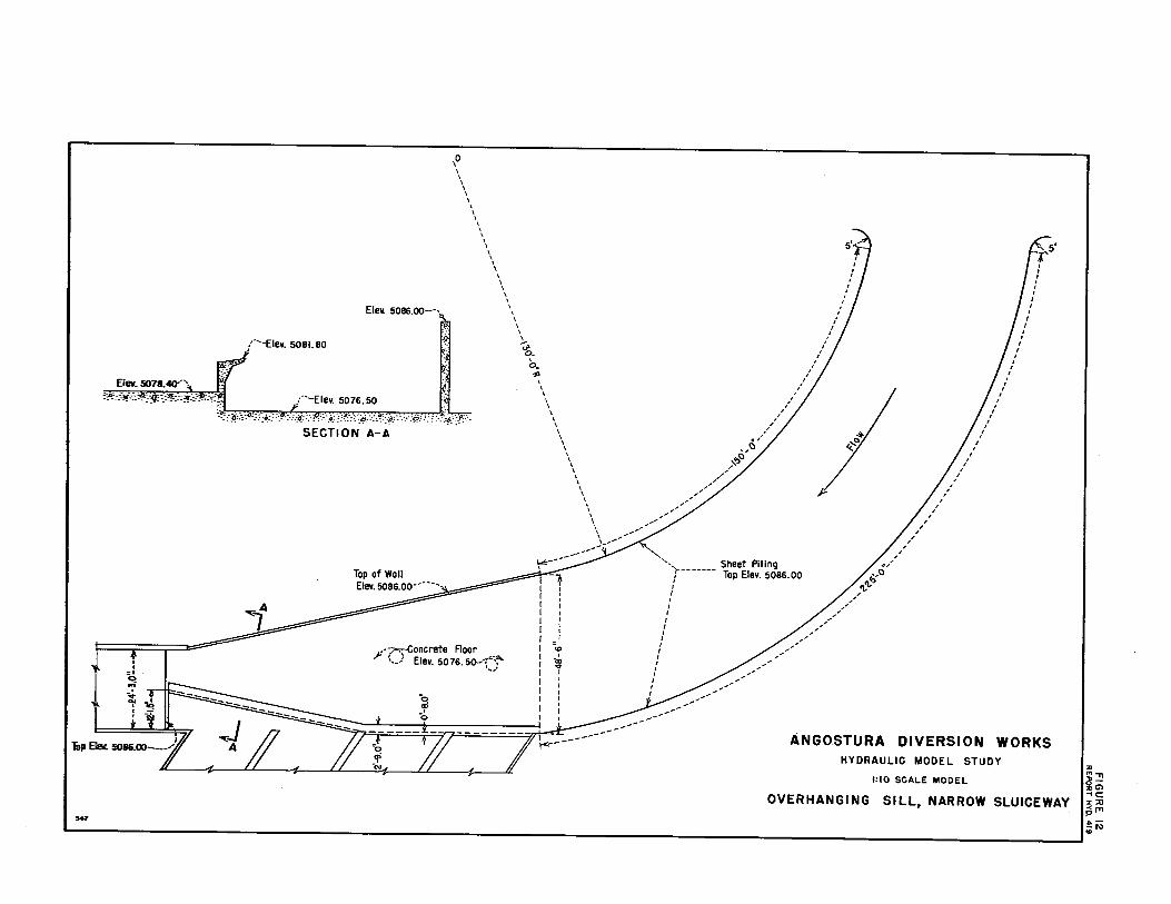
Overhanging Sill, Narrow Sluiceway, Test No. 6
The curved approach channel lost its effectiveness at about the entrance of the third bay of the head.works. In an attempt to extend the effectiveness of the channel, the zigzag overhanging sill was replaced with a straight overhanging sill in front of the first two bays and in front of the last two bays the overhanging sill diverged from the entrance of' the turnout to the middle of' the river sluiceway. The left half of the sluiceway was blocked off so that all of' the flow had to pass through the right half, Figure 12.
After a 16-hour test run the average sand concentration ratio was Cs/Cu = 1.06. This was a better ratio than that of the existing structure but fell far short of being as effective as the modifications of Test No. 4. ·The appearance of the sand bed at the conclusion of' this test is shown on Figure 13.
Approach Channel 4o-f'eet Wide, Test. No. 7
The next step in the investigation was to reduce the width of the approach channel to 4o feet, Figure 14. It was thought that the increased velocity'througb the narrower channel might extend the effectiveness of the curve farther downstream.
. This test was run for 23 hours and sediment conce.ntration samples taken during the last 5 hours showed the ratio Cs/Cs:• 2.98. The appearance of the sand bed at the end of this test is shown on Figure 15.
Right Half of Sluiceway Closed1 Test No. 8
Although the results of Test No. 7 were the most prani.sing that had been attained to date, it was thought that even better results could be attained by further changes to the · approach channel. The next
7

modification, accordingly, was to place the overhanging sill in a straight line at the entrances of all four bays of the turnout structure. In addition, the right side approach wall was converged downstream to the aluiceway so that at the upstream.end of the head.works the channel was 4o-f'eet wide and at the downstream end was one-half the width of the sluiceway, also the right half of the sluiceway was blocked off so that all of the flow passed through the left half, Figure 16. The reasoning for this being that the increased velocity along the overhanging sill should increase the effectiveness of the sill.
This test was run for 24 hours and sand concentration samples taken during the last 6 hours resulted in an average ratio of Cs/Cu= 6. 79. The appearance of the sand bed after this test is shown by Figure 17.
Flow 'l'hrougb Three Bays, Test No. 9
Visual observation of the bed.load movement in the previous test indicated that after the channel had reached equilibr1W'1, all of the bed.load that went into the head.works entered through the fourth bay. There seemed to be three methods of further reducing the amount of sediment moving into the fourth bay of the head.works. The first method was to increase the amount of sluicing water; short tests sho\red that this did reduce the amount of sediment entering the head.works but since the extra sluicing water was available only a small percentage of the time, other means of eliminating the sediment were tried.
The se~ond method of reducing the amount of sediment entering through the fourth bay was to close the gate .of this bay and to open the o~er three gates sufficiently to_pass the 500 cfs without raising the water surface elevation above 5084 .25. The operating time for this test was 25 hours and sand concentration samples taken during the last 3 hours resulted in the ratio Cs/CU • 0.39. Since this modification resulted in a sediment concentration ratio almost as poor as for the existing design, it was apparent that all four bays of the head.works had to be open in order to obtain good action with the sediment excluder. Figure 18 shows the appearance of the sand bed after this teat.
Vortex Tubes, Teats No. 10 and 11
The third method tried for reducing the amount of sediment entering the fourth bay of the head.works was to use a vortex tube in conjunction with the modifications described !'it Test No. 8. The vortex tubes were placed in front of the fourth bay at the leading edge of the overhanging sill, Figure 19. 'l'he vortex tubes were patterned after tubes that had previou•ly been foun4.to be eftective·in sediment removal.
8

However, the aligmnent of the tube with respect to the direction of flow was not the most desirable but was the best possible without interfering with the sluiceway flow.
The first vortex tube tested had a constant area for the f'Ull length. After a 29-hour test run sediment concentration samples gave the ratio Cs/cu = 32.98. Without the vortex tube the ratio for this model setup was 6.79. This represented a vecy large improvement and was accomplished with the downstream one-third of the tube covered. The tube was covered in order to make the upstream portion more effective since the model tube was capable of discharging only 10 cfs, and apparently at least 15 cfa would be necessary to make the tube effective along its full length.
The second vortex tube tested diverged ~n width from one end to the other in such a mmmer that the downstream end had about a 50 percent greater cross sectional area than the upstream end, Figtlre 19. Sediment concentration samples taken during two 5-hour intervals during a 53-hour test run showed the ratio Cs/CH = 3. 57. This was much poorer than the same model setup with the first vortex tube probably because the vortex could not draw a sufficient amount of water to carry off the sand and since the height or bullt of the tube prevented the overhanging sill :from exerting its action to keep the sand moving downstream, the sediment was building up behind the tube and moving into the fourth bay of the head.works. The same buildup had been noticed with the constant width vortex tube but there was sufficient discharge through the tube to carry off the sediment.
Figure 20 shows the sand bed in :front of the headworks after the tests with the vortex.tubes.
Approach Channel 30-feet Wide, Test lo. 12
Test No. 12 was run to determine the effect of a further reduction in the width of the approach channel. The width of the cllannel was reduced :from 40 to 30 feet, Figure 21. For expediency the main portion of the model remained the same as for Test No. 11, including the operation of the tapered vortex tube.
The increased velocity caused by the narrower channel resulted in very excellent sediment exclusion. Sediment concentration samples taken during the last 5 hours of a 29-hour test run shoved an average ratio Cs/ca • 'l7. 54. This was by far the beat result that .bad been obtained and when compared to the ratio of the first test where the ratio was Cs/CB• 0.17, the value or efficiency of the sediment excluder can readily be seen. Figure 22 shows the appearance or the sand bed after this test.
9
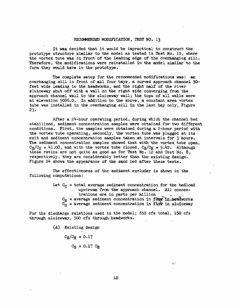
RECOMMENDED MODIFICATION, TEST NO. 13
It was decided that it would be impractical to construct the prototype structure similar to the model as tested in Test No. 12, where the vortex tube was in front of the leading edge of the overhanging sill. Therefore, the modifications were reinstalled in the model similar to the form they would have in the prototype.
The complete setup for the recommended modifications was: an overhanging sill in front of all four bays, a curved approach channel 30-feet wide leading to the headworks, and the right half of the river sluiceway shut off with a wall on the right side converging from the approach channel wall to the sluiceway wall; the tops of all walls were at elevation 5086.0. In addition to the above, a constant area vortex tube -was installed in the overhanging sill in the last bay only, Figure 23.
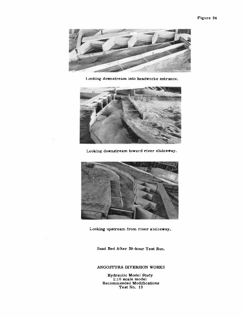
After a 24-hour operating period, during which the channel bed stabilized, sediment concentration samples were obtained for two different conditions. First, the samples were obtained during a 2-hour period with the vortex tube operating, secondly; the vortex tube was plugged at its exit and sediment concentration samples taken at intervals for 3 hours. The sediment concentration samples showed that with the vortex tube open, Cs/CH= 41.o8, and with the vortex tube closed, Cg/CH= 5.42. Although these ratios are not quite as good as for Test No. 12 and Test No. 8, respectively, they are considerably better than the existing design. Figure 24 shows the appearance of the sand bed after these tests.
The effectiveness of the sediment exciuder is shown in the following computations:
let CT= total average sediment concentration for the bedload upstream from the approach channel •. All concen-trations are in parts per million :-"" . ., _ .,,
~ = average sediment concentration in .r•'"'1'·1~ . .-iaworks Cs= average sediment concentration inf~ in. slufceway
For the discharge relations used in the model; 650 cfs total, ·150 cfs through sluiceway, 500 cfs through headworks.
(A) Existing design
Cs/CH = 0.17
Cs = 0.17 CH
~-. :.
10

,
150 Cs+ 500 CH= 650 CT
150 (0.17 CH)+ 500 CH= 650 CT
525.5 CH= 650 CT
~ = 1.24 CT
(B) Recommended design (without vortex tube)
Cs/Ci{ = 5 .42
Cs= 5.42 C}I
150 Cs + 500 Cu = 650 CT
150 (5.42 Ci{) + 500 ~ = 650 ~
1313.0 ~ = 650 ~
CH = 0.50 ~
( C) Recommended design (with vortex tube)
Cs/CH = 41.o8
Cs= 41.o8 Ci{
150 Cs+ 500 CH= 650 CT
150 (41.08 ~) + 500 ~ = 650 CT
~ = 0.10 CT
To summarize, assuming the sediment.concentration in the river is 1,000 ppn: with the existing design the sediment concentration in the head.works is l,24o ppn; with the recommended modifications and no vortex tube the concentration would-be 500 ppn; and with the recommended modifications and the vortex tube the concentration would be 100 ppn.
In order for the vortex tube to be effective in the prototype structure it must be able to discharge between 15 and 20 cfs. At this location it would not be possible to obtain sufficient natural head to draw this much water; the vortex tube would have to be connected to a sediment pump capable of pumping 20 cfs against 15 feet of head. This pump should be operating at all times when water is being diverted into the head.works.
11

Head Loss
When the flow was channeled between the curved walls there was a slope in the water surface, or head loss, that varied with the distance between the walls. In the model the magnitude of the slope was determined by measuring the difference in elevation of the water surface on each side of the right approach wall near the river sluiceway. Since the water was not flowing on the outside of the wall, this was comparable in the prototype to finding the slope of the water surface in the approach channel from the entrance downstream to the river- sluiceway. Of course, the absolute elevation will depend on the actual water surface elevation at the approach channel entrance o The difference in elevation as determined from the model is listed below for the three widths· tested.
Width feet
Sand Bed Movement
48.5 4o.o 30.0
Change in elevation feet
o.4o 0.65 1.00
Whenever any of the tests first started there was considerably greater difference in water surface elevation than shown in the above table, however, after a few hours ' operation the sand bed would become stabilized and the head loss become consistent. During the period the channel was becoming stabilized, the sand would move into all four bays ot the headworks and progressively, as the channel bed leveled off, the sand stopped entering Bays 1, 2, and 3. The slopes of the channel beds for various tests are shown in Figure 27; generally speaking, the slope of the channel bed corresponds to the slope of the water surface. In keeping with the theory of the curved walls, the sand bed at the outside
.of the curve is at a lower elevation than the sand bed of the inside of the curve once the "roping" action of the curve becomes effective.
12

<> < .., <>
' .. 0
,. "' ,. .. ~ 0
;;i . ' " ' ~ ; ?
Cl en
"' "' 0 § QO
;e CD QO
:e 0
V
2 0
~ 0 • ..,
2 !"
" ~ ~ .,
"' ~ " • -< .. 0
5
. 0
Mc.
/
A
G)
fl1 2 fl1 :0 )>
r
~ )>
"0
L
(/)
J>
z
'-
C
J>
z
oLAKE CITY
R 0
1· -----·-----Regin
I ,.,,,, ... ,, /,,9 ,
' ~ -;= _ _ ___j___ _ _ _ fl )
r---:V '~ '" -- I i' /,-J \\1· _ti I J
N L E y / \ / ' K
,,,...-__ ,;
• ~ e
ESTANCIA
T 0 R A N
' .. I \
L----- -- "' "' 0 ... ~
00 ,,
o" ~ ,. zZ 2 3:
,,,o .,,,. ~ "
,,,, <"' "' ; ,.
"' z O
R
z o" ,.
0 " "' a: "' "' o-
;, ... -o
"' ,. U>o ... -<,- 0
0 "? ... C:
0 ~ z ... ,, 0
,.
" =!
: z 0
""
LOCATION MAP
C E
I "' i X
"' --0 ;;; r ,. J> ... "' z 0 J> .... -< ,. z 0 0 z "'
I ::0 ..,, -0 o-,, ::o--< G> c:: I::o
,<..,, ,;:, ...... ~ ..... ID

,,-Floor Intake sluice ,,-Canal intake : El. 5076.50 :s-e.o'x&.67' / ,-2-11.92'x 8.89' \ ,Top of guide wall Cone. boxes-, : I Radial gates \ : El. 5083.0 . Settling channel \ : \ ,•El. 5072.94 l \ ,--Topofconc.El.5084.50 ,: : \ : ,-·Bottom sump-El.5071.0
FIGURE 2 REPORT HYD, 419
1 , . f ·~ C::2'! ~::;Y'';:tm: 111 ''H''' 011 ·fl ·tf'·,m .. , ·~···~1 "1t3'.('''Mm~J~ mJJ,I' WiM,3 1 ',, i, '' 'Y 4-20.dx4.6' / ! l--Polnt A,El.5075.18 El.5074.20-· ! El.5073.38• I j ·El.5073.0
547
Radial gates,· l.----------1290'-- ____ _,___ - ---.:..-------390'------* 149.75~.l----------------268 7'± To river------+----
i-SECTION A-A
,:Ii. Canal r. ' ,-Settling channel +t ( Depth 9.32' to 10.30'
t<-2d-d!o.! ~ : ki!d-o'!o-1 . ,. I .. ,... I I .I I~
1114#$. ·~~ rr·z.l fir'• .... I k--32~0'·--..J
SECTION B-B
·i -,i.
' • .-·:r ------20-0------..i -12'Steei sheet piling
SECTION Y
Arroyo bed-·1 :zzacai.attJ zaai c :..wz :www
{:
9'
rJ, SECTION C-C
__ t "o
' _:t_ r I I I
--t--------3dd'---------- I ----- 20'0'' ------>l 9~ \ .. ,o"x1611 Conc.sill , ~ 12" ••
under cont.joints. ·-12 Steel sheet p.hng SECTION X
RIVER WEIR
{River bank ,.·· 1_ Rail-wire protection
. \. River weir
,--Intake transition \
.-Rail-wire protection
Crest El. 5083.0
--,--t) '·Angosturo
Arroyo--, t")'
j/ C
-i
,• Canal intake transition I
\ \ \ \
----------<{ '·-Concrete boxes '·--Wasteway channel
ANGOSTURA D.IVERSION WORKS HYDRAULIC MODEL STUDY
1:10 SCALE MODEL
GENERAL LAYOUT
< ..

547
··l-from Supply Channel
upply Pump
~-- _____________________ - -- ---31'-o" - -- -- - - -
. ' ' I
I \
,hack Baffle
\ . ' ' /
San.d Feeder Line----; ~
0
r--------7! 5¼~--------~---4'-si ·----1 I I
,--Sand Pump --'
I -::.0, I ,n
: I 3• -.:, f....--3-0;r~ I
----------~-t I I
___ ,..
ANGOSTURA DIVERSION WORKS HYDRAULIC MODEL STUDY
1:10 SCALE MODEL
MODEL LAYOUT
.. ,.,.,, ,,_ oc:, ~c :c::U ~rr,
... "' ii

547
/-Elev. 5081. 80
(Elev. 5083,00
f ~
Elev. 5078.40--,
=o ,.;
-i I I
\ : :a: :o: ·: :·-~ 1-·-E lev. 50 76. 50 I ...... ::~_.-_:;~·:-_:.~-/,;._.·.-:·:~:·-<·:=.-::~· .. :.--.:--.-:_.:._\)_- :- -: ::,<v':. ·_:; :/:}.
SECTION A-A
\-Radial Sluice Gate
=(D _,
-<-Flow
Elev.
---,,: I I I I I I I I
=o <D .I co ..,. I I I I I I I I I
/Elev. 5081.80
1-··Elev. 5076. 5
SECTION B-8
Y I )I - __,,_... v v.g " i 1'--- ;f I r<;/ t tz · 17 ?711--N
,; ;) ;) j
PLAN
ANGOSTURA DIVERSION WORKS HYDRAULIC MODEL STUDY
1: 10 SCALE MODEL
PRELIMINARY DESIGN
::u !ti ,, 'Tl o::u Ci) --ic :c ::0 -< I'll 0
~~ (D

Looking downstream into headworks entrance.
Looking downstream toward river sluiceway.
Sand Bed After 55-hour Test Run.
ANGOSTURA DIVE;RSION WORKS
Hydraulic Model Study 1: 10 scale model
Preliminary Design Test No. 1
Figure 5

1147
I I
~ :; I I
,,..--e:lev. 5081.80
(""Elev. 5076,50
-Radial Sluice Gate
··-Elev. 5083.00
PLAN (A) OVERHANGING SILL OR CORBEL
SECTION A-A
("Elev. 5081.80
r·Elev. 5076.50 /
FIGURE 6AfUB REPORT HYD, 419
- ~~~--r ~ -~
'·-Radial Sluice Gote
PLAN
(B) ZIG ZAG PATTERN FOR CORBEL
-: I I I I I I I
-=---i
ANGOSTURA DIVERSION WORKS HYDRAULIC MODEL STUDY
1:10 SCALE MOOEL
OVERHANGING SILL STUDIES

Looking downstream into headworks entrance.
Looking downstream toward river sluiceway.
Sand Bed After 48½-hour-Test Run.
ANGOSTURA DIVERSION WORKS
Hydraulic Model Study 1: 10 scale model Overhanging Sill
Test No. 2
Figure 7

SECTION A-A
547
,o \ \ \ \ \ \ \ \ \ \ \ \ \ \ \ \ \ \ \ \ \ \ \ \ \ \
\ \ l-
\ .,, \ \ \ \ \ \ \ \ \ \ \
' \ \ \ \ \ \ \ \ \ \ \ \ \ \ \
\ -""'---------"'- --
----- ________ Sheet Piling T Top Elevation 5086.0 \
I I I I
I , • I ,' ~ ,,
I
I ,,
,'
~ ,,,,,,,, .,o
"'., ~'1, ,,
15' I I
! I :
/ : I
: : I
I I
I I
·I : /
/ /
I
/ ///
,,,,,
,,,'
...-·r;-·concrete Floor ·-· Elevation 5076_5--(1~ . .. _,,
I ,, ~ __ ,,.,, I , I ,' I ,'-I ,/ I / I /' : _,,---1 _.,.,
---- ::,------------------- A NGO STU RA DIVERSION WORKS HYDRAULIC MODEL STUDY
1:10 SCALE MODEL
CURVED APPROACH CHANNEL WITH ZIG-ZAG OVERHANGING SILL
., ,,,.,.,!., G.. c:,: :u-<rrp !G.,

Looking downstream into headworks entrance.
Looking downstream toward river sluiceway.
Looking upstream from river sluiceway.
Sand Bed After 21 ½-hour Test Run.
ANGOSTURA DIVERSION WORKS
Hydraulic Model Study 1: 10 scale model
Overhanging Sill and Curved Approach Channel Te~t No. 4
Figure 9

547
,0 \ \ \ I I I
1~Elev. 5086.00
,-·Elev. 5081. 80 .-o'-8.2"
. , :"\ f. Elev. 5078.40· ~j Elev. 5076.50' __ .;, ...... , .. ,:i'. .. _.,, .... _. . -.<?,:.<>· •• :~,,;4, . .-o::, .•,-::~::·}!:·:.:p:-,; ·,':'.:!=!·:,.'>:::rs.·:·': .o ... ·'· .. -~.
SECTION A-A
\ \ I I
\ \ I \ \ I \ \ \ \ \
\
\ \ \ ' \ I
\ ,' ~ I ~ I ' ' ~ I ~ I \ I
' ' \ ·/ \ I \ I \ /
\ I \ ,' \ ,' \ /
\ I \ ., \ .. ,o \ ~ \ ,,,,, .......
\ / \ , \ ,,, \ / \ ,, \ / \ / ' ,,,'
\ / \ ........ , ·,
1,c,----------\.--\
',,,,..,.. _____ sheet Piling \ Top Elev. 5086.00
CD
' <X>
I \ I
'
/
/ ,/ _,,
.,,,,,'
,,,' ~ ,,
/
,,c::, 'l,tj ,,"'
/
I
I
, /
' ' I I
I
I I
I
'
' ' '
I I
~;,---~--Concrete Floor ',-' Elev. 5076. 50""7·~,
'·--'ii ..
I I
/ /
/
., ... ,""
~ -.. "' I
I
"o .,;
-.......... "",
ANGOSTURA DIVERSION WORKS HYDRAULIC MODEL STUDY
1:10 SCALE MODEL
VERTICAL WALL IN FRONT OF TURNOUT ENTRANCES
:u ....... ;g-:u Gl -IC x::o ?m .,._ io 0

Looking downstream into headworks entrance.
Looking downstream toward river sluiceway.
Sand Bed After 31-hour Test Run.
ANGOSTURA DIVERSION WORKS
Hydraulic Model Study 1:10 scale model
Vertical Wall At Headworks Entrance Test No. 5
Figure 11
547
. . =• 0 ... ; . '
Ele1t 5086.oo---.._,
('-Elev. 5081.80
{'-Elev. 5076. 50
SECTION A-A
\0 \ \ \ \ \ \
\ \ \ \ \ I \ \ \ \ \ I
\ \ I I I I
F-~oncrete Floor _ , __ _. Elev. 5076. 50---r~-~
' ......
I I
-i,5' I I I I I
' I I I
I \ I ~ ' ~ I ~ . ~ ; ~ I
I I I
I I
I 0
I / \ , I / I ,
\ ,' \ , I , I ,
I ,' \ , \ / \ . , \ i{r::, \ ,.,.,
I ,' \ / I ,' \ ,
I ,' \ / \ / \ ,,,,' I ,' \ / \ /
'""' ________ --;---" ·-.. Sheet Piling
CD
' ·m ... I
r------ Top Elev. 5086.00 I I I I I
I I I I I I I
----------
/ _,, .,,, ... .,. ... ~
,, ,.//,,,
/
,, / ,,
.. ,o,' 'l,o;
,,/''I;, ,,,
,,,,,· ,'
,,,'
, . /
,' I
/ I
,./
ANGOSTURA DIVERSION WORKS HYDRAULIC MODEL STUDY
1:10 SCALE MODEL
OVERHANGING SILL, NARROW SLUICEWAY
:u "'"Tl ~-"' G) -, C :,: :u ~"1
~I\} .,

Looking downstream into headworks entrance.
Looking downstream toward river sluiceway.
Sand Bed After 16-hour Test Run.
ANGOSTURA DIVERSION WORK.q
Hydraulic Model Study 1: 10 scale model
Overhanging Sill and Narrow Sluiceway Test No. 6
Figure 13

647
,--·Elev. 5081.80
Elev. 5078.40
Elev. 5086.00---1
./•I 1'.t!
\~
\ \ I I \ \ \ I \ \ \ \
\ \ \ \ \ \ I I I I I \ \ I I \ I \ )..
~ I ' I ~ I
,,,; .. _:.-,_,f<?!-:=.=.-,?i.,.-.-.·.-•. :-,,, ... , .. ,,~-:%tj_:; .. #,:.:x . .-·~f~.~-:--~~.~~:-.:.~.!~-=~g ___ ·::.1?-.:·.- . .-.P..:}k_. -,0 I \ I \ I \ ,
\ I \ I \ ,'
SECTION A-A \ I \ I \ I
\ / I , \ ,/
I , ,Q
\ ~Q \\ ,,, ...... "
\ , \ / I ,' \ ,;I'.,,'"
\ ,, \ ,\ .,.,"
\ ,-
Top of Woll ••• \"""_;:,,-' EIH 5086.00·' \ 'i 'f
.Q I I
,,,--r. ··-..-sheet Piling
Top Ele115086.00
---/ ,-·
/ ,
,// / _,,
•/ ~<:J
"'"' /
/ I
,'
/
I I
I
,'
t'5' I
I ! :
I I
I I
: I
I
: I
I , ,'
I , , , , ,' ,
J I i I I .: ,--~oncrete Floor I .9 y '...J Ele11 5076.50 ·_:-"!\ I 1
/ ,, ,,- /
\ _ _J.~ I : I I I I I
__________________ /-
ANGOSTURA DIVERSION WORKS HYDRAULIC MODEL STUDY
1:10 SCALE MODEL
APPROACH CHANNEL FORTY FEET WIDE
ill ... c1l-:uG> -tC :r :u -< ITI p :t. ...

Looking downstream into headworks entrance.
Looking downstream toward river sluiceway.
Sand Bed After 23 -hour Test Run.
ANGOSTURA DIVERSION WORKS
Hydraulic Model Study 1: 10 scale model
Approach Channel 40-feet Wide Test No. 7
Figure 15

547
Elev. 5086.00··---.,
,·Elev. 5081.80
Elev. 5078.40-'\ ,... ll!: '!!/::~;:_:~,: ?~-=-::• = ':\M:·::!>.f;f/~:~,:-~:~~6,~7:~·ii)!}':C_,:·~:·(:~}.:,if::}·: :.-~,=~;·:'
SECTION A-A
•• ----Top of Woll Elev. 5086.00
,o I \ \ \ I I \
' I \ \ \ \ I \ \
' I I I I \ \ \ \ \ \ \
~ <P.
I
"'· ' I \
' \ ' I
\ \ \ \
' \ \
' \ ' \
\ \ I \ I \
\ ' \
\ ,--""'" _________ --:..:- )"---Sheet Piling Top Elev. 5086.00
, t_).---Concrete Floor _,/ I ""<-•"' ,,., • , Elev. 50 7 6. 50 · -,.-.,\ _,, -~ . __ _. _____________ ,,
,,,' +/
,,,,,,,,/
.,o ..,,., ,'I,
,,,,/',,,.
,,,,,.,,,,.
, ,
/,,' ,
, I
, ,
, , ,
, , ,
I
I
' '
. . ' . . .
J ' ' . .
' ' . I
I
' I I
/
-rs· I
! I
I ~---------------....L----¾-----------. ,,-l:========~==t===r7===~;=.;:=~==-=;;'7-======m-= ------ ----- ANGOSTU RA DIVERS! ON WORKS HYDRAULIC MODEL STUDY
1:10 SCALE MODEL
RIGHT HALF OF SLUICEWAY CLOSED
:0 ~.,, 0-:0 C, -tC :r :u ~1'1 .;;; a,

Lookin.l:! downstream into headworks entrance.
Looking downstream toward river sluiceway.
Sand Bed After 24-hour Test Run.
ANGOSTURA DIVERSION WORKS
Hydraulic Model Study 1:10 scale model
Right Half of Sluiceway Closed Test No. 8
Figure 17

Looking downstream into headworks entrance.
Looking downstream toward river sluiceway.
Sand Bed After 25-hour Test Run.
ANGOSTURA DIVERSION WORKS
Hydraulic Model Study 1: 10 scale model
Flow Through Three Bays Test No. 9
Figure 18

.0 \ I I \ \ \ \
Elev. 5086.00---··-., \ \ \
,:9 I \ I I \ \
__ ..Elev. 5081. 80
···see Detail N YI \ I I ' , I 5'.;1-~
r •. .t .... ,-:-. -~--~.:..- -~;-- .. ·A .• -,,~-, ::;·-.-N,'-~·:::>~·:-·:·':'
SECTION A-A
B C D ["j?:------ -30'-o'--+------1 ft!"-----------30' -o'---+-------~
\ I I ' \ I I I
\ / I ' \ ' ' I ~ ' cP.. / ~ I -,, I
' I \ ' \ I \ , \ I \ I \ /
\ I x--'.§§ x--§g----,; ! f_ ! f__ __i ! ~~ b~ ~~ . . t\i~ . d
\ / \ /
\ I I / ,::,...'\J/ / '
,/' T 1-- _ T l- -~~_1 1---~ ~---~ :t
B :> PLAN ;:,. PLAN -<: D - DETAIL N C
I
li9-'?,.
ELEVATION B-B STRAIGHT TUBE
I I I I
=C'?
"' -~
k4.8'"' I I ' . I
(~.;;;J ,f>
ELEVATION C-C ELEVATION TAPERED TUBE
\ .... ,, \ ,fa \ ,.,o
\ / \ / \ /
\ / \ / \ / \ / \ / \ ____ .,,.
\ / , __ __
·---.,.. ______ Sheet Piling \"""-----------) / Top Elev. 5086.00
0 -~ ..
I
'
! '
.. ,,' __________ ,,-----
/
/ /
,,, /
/ /
/ /
/ ,.,,'
.. ,O' 'I,.,
,ci;
,' ,,'
/ /
/
,,,,'
' ' /
'
' ' '
ts' ' ' ' ' ' /
I ' I
I /
ANGOSTURA DIVERSION WORKS HYDRAULIC MODEL STUDY
I: 10 SCALE MODEL
VORTEX TUBES
547
"' m"TI -u-0 C)
"'c -, ::u ~!Tl P_ ... U) iii

Lookin~ downstream into headworks entrance.
Looking downstream toward river sluiceway.
Sand Bed After 29-hours Operation For Test No. and 53-hours Operation For Test No. 11.
ANGOSTURA DIVERSION WORKS
Hydraulic Model Study 1: 10 scale model
Vortex Tubes Tests Nos. 10 & 11
Figure 20

847
0 \ I \ I \ \ \ \ \ \ \ \ \ \ \ \
\ \ \
\
Elev. 5086.00··-.
,·Elev. 5081.80
Elev. 5078.40---, ~ ,.
,,s.;-Ac.·:is--::·.6:·f.:.i:.<>:j ··Ele~ 5076 50 I · · ·· ·· ·- ··· · · · --~~-~-::q~"' _t.\ .".D: .. :':._cr:· :-~:::"._-_._o_-·;i.:-:::t:9'·.=-~9·:
I • I
~
SECTION A-A
.----Top of Woll ./ Elev. 5086.oo--\
,_ ...... - \. A
-<; • ..-.;·-Concrete Floor ~ :.._i Elev. 5076. 50 ·;;,-.,"\
\ \ \ I \ \ \ \ \ \ l..
~ a,. ,ii
\ \ \ \
' \ \ \ \ \ \ \ I \ \ \ \
' \ I I I \
' \
14-------------~---,---' I
/ _, ,, -
,, .. ,a'
:,.<:>a ____ ,,,
'"·,--·Sheet Piling I Top Elev. 5086.00
I I
I I
I
,'
/ , /
,,,' ,
,, /
,,,,'
/ ,,.,,,' ,,
,,,'
•' _,a ~ ,'V
! i --,
I
' I I I
' ,, ,, ,,
,, ,/
/
,,
/ ,,,'
/ /
I
~5' I ,
I I ,
I I I I I I
I I
I I
I I
I I
I I
I I
I I
I I
I I
I I
/ :
,,/
/ /
'* I I
• .. _)
-----------''
ANGOSTURA DIVERSION WORKS HYDRAULIC MODEL STUDY
1:10 SCALE MODEL
APPROACH CHANNEL THIRTY FEET WIDE
:a ~"11 o-.,.., -IC: :,: ;u -< ITI p ... I\) ;;;-

Looking downstream into headworks entrance.
Looking downstream toward river sluiceway.
Sand Bed After 29-hour Test Run.
ANGOSTURA DIVERSION WORKS
Hydraulic Model Study 1:10 scale model
Approach Channel 30-feet Wide Test No. 12
Figure 22

047
,-see Detail N ,;---, --Elev. 5081.80
\ :i· )
,-Top of wall at .; Elev. 5086.00 ..
Elev. 5078.40 , __ _, ..
"'''""'f i~:+}ci +t:r,s;i;, ,>,,J SECTION A-A
-,.;--i\o \ \ \
' ' \ I I I I I I \ I \
\ \
'l--..., _, ~
I I I \ I I I I I I I I I I
$ ~ a>. ""?
I \ I \ I I
I I I I
DETAIL N I I I I I I I
------------------ -----i
,Top of wall at [ Elev. 5086.00
---------------eo' 7.8" ----- -------.-! <.A
PLAN
~---Concrete floor r'C) Elev. 5076.50 ··, ,-.. ., ·-~
\ I \
\ \
' I I I I
' I I I \ I I I I I I I I I I I \ I
/ / ,,,,,. ,,,,,.
,-' /
,.,.,"
,,,,' / .,,
.,a ,f>Q
_,.,-'
/,,/ ,'
, /
,,,,, ,'/
, , , /
l-..,,, /
/
ANGOSTURA DIVERSION WORKS HYDRAULIC MODEL STUDY
1:10 SCALE MODEL
RECOMMENDED LAYOUT
:0
~:!! l;lG> -<C :,::;o pm ""' '°"'
Looking downstream into headworks entrance.
LookinJ? downstream toward river sluiceway.
Looking upstream from river sluiceway.
Sand Bed After 29-hour Test Run.
ANGOSTURA DIVERSION WORKS
Hydraulic Model Study 1:10 scale model
Recommended Modifications Test No. 13
Figure 24

Cl
~ 00 .. u,
I
9086
5084
5082
9080
9078
5076
5086
... "' UJ 5084 .. z - 5082
z 0 j:: 5080 <[
> "' ..J 5078
"' 5076
50SS
5084
5082
5080 I
5079 I
CURVED GUIDE WALLS THIRTY FEET APART
Water surfoce-· \ -- --- - _,.. -1-- _____ -.... Right waif··,"-. ----------- ------ ----- ----- -·- .... -- -- -- - ~----........ .... _ •.:.Center line i------- -- --r::r----- ------ -----------Lett wall·----- ------ ------
CURVED GUIDE WALLS FORTY FEET APART
Water surface···
'" Right wall·"\ ....... -
------- -,,,,,.,.,.---'\ - --- ------------- r---. __ -- Center line --i--.. --- ·- ___ .......,_ --
------~ ~-......... . ... i,....----- 1------ ---- .... Left wall.Jr- '-... ------ -------~------ ------
CURVED GUIDE WALLS FORTY-EIGHT AND ONE-HALF FEET APART
Water surface - )
Center line--,, --- ----- ~ ~-i-----. ., --- - ---_,,.,.. .......... .- --__.J:-· - - ____ -:::.:
r---,,,.. -- ~ ---- ---- ------ r------,,,.. --· ,,,..- ..... , --.... - --l· -.... ,·Left wall --,j --~-'-Right wall -- _: __ .,,,.,,,,,,. -~ ~----- ------5078 "a 20 40 60 80 I •v 120 140 160 180 200 220 240
547
DISTANCE UPS TR EA M FROM SLUICEWAY ENTRANCE· IN FEET
Turnout .structure __L> Approach
channel
ANGOSTURA DIVERSION WORKS HYDRAULIC MODEL STUDY
1:10 SCALE MODEL
SANDBED PROFILES IN APPROACH CHANNEL
.. 0
"' ; .,, o,,~ -iC :,: :u -< JTI p .. I\) - (JI .,