Embed Size (px)
Citation preview
UNITED STATES AIR FORCE AIRCRAFT ACCIDENT INVESTIGATION
BOARD REPORT
F-15E, T/N 90-0235 391ST FIGHTER SQUADRON
366TH FIGHTER WING MOUNTAIN HOME AIR FORCE BASE, IDAHO
LOCATION: SOUTHWEST ASIA
DATE OF ACCIDENT: 28 MARCH 2012
BOARD PRESIDENT: BRIGADIER GENERAL
CHARLES L. MOORE, JR.
Conducted in accordance with Air Force Instruction 51-503
EXECUTIVE SUMMARY AIRCRAFT ACCIDENT INVESTIGATION
F-15E, T/N 90-0235, SOUTHWEST ASIA 28 MARCH 2012
Under 10 U.S.C. § 2254(d), the opinion of the accident investigator as to the cause of, or the factors contributing to, the accident set forth in the accident investigation report, if any, may not be considered as evidence in any civil or criminal proceeding arising from the accident, nor may such information be considered an admission of liability of the United States or by any person referred to in those conclusions or statements.
On Wednesday, 28 March 2012 at approximately 1603 Zulu (2003 local time), the Mishap Aircraft (MA), an F-15E, Tail Number 90-0235, impacted the ground approximately 18 nautical miles west, southwest of the deployed operating location of the 391st Expeditionary Fighter Squadron in Southwest Asia. The Mishap Weapon Systems Officer (MWSO) initiated ejection for the Mishap Crew (MC) and ejected safely with only minor injuries. The Mishap Pilot (MP) was fatally injured when his ejection sequence was interrupted by contact with a 377-foot tower that was part of a large radio tower array. The MA was destroyed after contacting the radio tower and subsequently the ground. The MA loss is valued at $47,094,662.60. The MA caused damage to Host Nation property. The MC was participating in a large force exercise as the flight lead of a two-ship of F-15Es in a strike package of approximately 27 aircraft. At the conclusion of the tactical portion of the mission, the MC removed their night vision goggles (NVGs) and proceeded back to the base. Below 10,000 feet above mean sea level (MSL), blowing dust and sand obscured the horizon (with or without NVGs). At approximately 3,100 feet MSL, five degrees nose low and in a wings-level attitude, the MP incorrectly interpreted the visual scene in front of him and began a series of abrupt maneuvers that ultimately resulted in him rolling the MA into an inverted attitude 1,800 feet above ground level and 25 degrees nose low. Due to the lack of any significant topographical features, the expected lack of cultural lighting, the reduced visibility and the lack of a discernable horizon, the MP became disoriented by the cultural lighting in the vicinity of the mishap site and incorrectly perceived that the MA was inverted. This misperception caused the MP to roll the MA into a truly inverted attitude, at which time the MWSO became convinced the MP had become disoriented and took control of the MA. After attempting to recover the MA, the MWSO initiated ejection for the MC. The evidence suggests that the MP did not have the electronic attitude director indicator (EADI), the primary source of aircraft attitude, up on any of his cockpit displays at the time of the mishap. The MP was likely using his head-up display and the visual environment as the source of his attitude. Subsequently, visual stimuli from light sources on the ground caused the MP to misinterpret his attitude and because this illusion was so strong, he initially did not make any attempt to call up the EADI or confirm his attitude with his standby instruments. Instead, he maneuvered the MA in accordance with his mistaken visual interpretation of his attitude and flew the MA into an inverted position. By not having the EADI in his crosscheck, the MP lacked a vital instrument that could have helped him avoid or overcome his disorientation. In addition, the combination of environmental and procedural aspects of the approach to the base created an environment where the MP was very susceptible to a visually induced illusion and offered a very small window of opportunity with which to correct his misperception. The Accident Investigation Board (AIB) President found by clear and convincing evidence that the cause of the mishap was the MP becoming spatially disoriented due to a visual illusion during his nighttime recovery to his deployed operating location. Further, the AIB President found by a preponderance of the evidence that the following factors substantially contributed to the mishap: (1) the lack of an effective instrument crosscheck by the MP and (2) a combination of the environmental and procedural factors present on the approach to the base.
F-15E, T/N 90-0235, 28 March 2012 i
SUMMARY OF FACTS AND STATEMENT OF OPINION F-15E, T/N 90-0235, SOUTHWEST ASIA
28 MARCH 2012
TABLE OF CONTENTS TABLE OF CONTENTS ................................................................................................................. i COMMONLY USED ACRONYMS AND ABBREVIATIONS .................................................. iii SUMMARY OF FACTS ................................................................................................................ 1
1. AUTHORITY and PURPOSE .............................................................................................1 a. Authority ........................................................................................................................1 b. Purpose ...........................................................................................................................1
2. ACCIDENT SUMMARY ....................................................................................................1 3. BACKGROUND .................................................................................................................1
a. Units and Organizations .................................................................................................2 (1) ACC ........................................................................................................................ 2 (2) 12 AF ...................................................................................................................... 2 (3) 366 FW.................................................................................................................... 2 (4) 366 OG .................................................................................................................... 2 (5) 391 FS ..................................................................................................................... 3
b. F-15E Strike Eagle .........................................................................................................3 4. SEQUENCE OF EVENTS ..................................................................................................6
a. Mission ...........................................................................................................................6 b. Planning .........................................................................................................................6 c. Preflight..........................................................................................................................6 d. Summary of Accident ....................................................................................................7 e. Impact ............................................................................................................................9 f. Egress and Aircrew Flight Equipment .........................................................................10 g. Search and Rescue .......................................................................................................11 h. Recovery of Remains ...................................................................................................12
5. MAINTENANCE ...............................................................................................................12 a. Forms Documentation ..................................................................................................12 b. Inspections ...................................................................................................................13 c. Maintenance Procedures ..............................................................................................13 d. Maintenance Personnel and Supervision .....................................................................13 e. Fuel, Hydraulic and Oil Inspection Analyses ..............................................................13 f. Unscheduled Maintenance ...........................................................................................14
6. AIRCRAFT AND AIRFRAME .........................................................................................14 a. Condition of Systems and Structures ...........................................................................14 b. Repair and Testing Stations .........................................................................................14
(1) Flight Control Components ................................................................................... 14 (2) Maintenance Data Transfer Module (DTM) ......................................................... 15 (3) Electromagnetic Interference (EMI) ..................................................................... 15 (4) Engine #1 and Engine #2, F100-PW-229.............................................................. 15 (5) Standard Flight Data Recorder (SFDR) and Crash Survivable Memory Unit
(CSMU)................................................................................................................. 15 (6) Egress Analysis ..................................................................................................... 16
F-15E, T/N 90-0235, 28 March 2012 ii
c. Functionality of Equipment .........................................................................................16 7. WEATHER .........................................................................................................................16
a. Forecast Weather .........................................................................................................16 b. Observed Weather ........................................................................................................16 c. Space Environment ......................................................................................................16 d. Operations ....................................................................................................................17
8. CREW QUALIFICATIONS ...............................................................................................17 a. Mishap Pilot Training ..................................................................................................17 b. Mishap Pilot Experience ..............................................................................................17 c. Mishap Weapon Systems Officer Training..................................................................18 d. Mishap Weapon Systems Officer Experience .............................................................18
9. MEDICAL ..........................................................................................................................19 a. Qualifications ...............................................................................................................19 b. Health ...........................................................................................................................19 c. Pathology/Toxicology ..................................................................................................19 d. Lifestyle .......................................................................................................................19 e. Crew Rest and Crew Duty Time ..................................................................................20
10. OPERATIONS AND SUPERVISION .............................................................................20 a. Operations ....................................................................................................................20 b. Supervision ..................................................................................................................20
11. HUMAN FACTORS ........................................................................................................21 a. Spatial Disorientation (Type 2) Recognized ................................................................21 b. Vision Restricted by Meteorological Conditions .........................................................26 c. Channelized Attention .................................................................................................27 d. Breakdown in Visual Scan ...........................................................................................27 e. Expectancy ...................................................................................................................28 f. Error due to Misperception ..........................................................................................28 g. Air Traffic Control Resources .....................................................................................29
12. GOVERNING DIRECTIVES AND PUBLICATIONS ...................................................29 13. ADDITIONAL AREAS OF CONCERN .........................................................................30
a. EADI Use .....................................................................................................................30 b. VSI / Lip Light / Instrument Lighting..........................................................................30
STATEMENT OF OPINION ....................................................................................................... 32 1. OPINION SUMMARY .....................................................................................................32 2. DISCUSSION OF OPINION ............................................................................................32
a. Cause: Spatial Disorientation of the MP .....................................................................32 b. Substantially Contributing Factors ..............................................................................33
(1) Lack of an Effective Instrument Crosscheck by the MP ....................................... 33 (2) Environmental and Procedural Aspects Present on the Approach to the Base ..... 34
3. Conclusion .........................................................................................................................34
F-15E, T/N 90-0235, 28 March 2012 iii
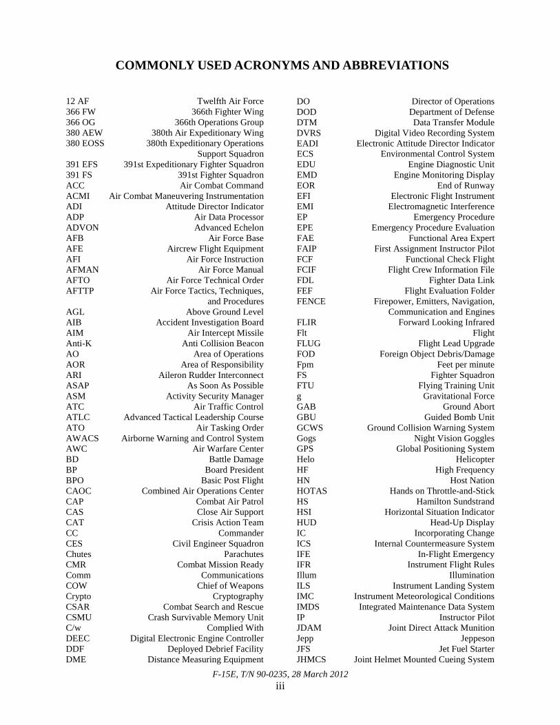
COMMONLY USED ACRONYMS AND ABBREVIATIONS
12 AF Twelfth Air Force 366 FW 366th Fighter Wing 366 OG 366th Operations Group 380 AEW 380th Air Expeditionary Wing 380 EOSS 380th Expeditionary Operations Support Squadron 391 EFS 391st Expeditionary Fighter Squadron 391 FS 391st Fighter Squadron ACC Air Combat Command ACMI Air Combat Maneuvering Instrumentation ADI Attitude Director Indicator ADP Air Data Processor ADVON Advanced Echelon AFB Air Force Base AFE Aircrew Flight Equipment AFI Air Force Instruction AFMAN Air Force Manual AFTO Air Force Technical Order AFTTP Air Force Tactics, Techniques, and Procedures AGL Above Ground Level AIB Accident Investigation Board AIM Air Intercept Missile Anti-K Anti Collision Beacon AO Area of Operations AOR Area of Responsibility ARI Aileron Rudder Interconnect ASAP As Soon As Possible ASM Activity Security Manager ATC Air Traffic Control ATLC Advanced Tactical Leadership Course ATO Air Tasking Order AWACS Airborne Warning and Control System AWC Air Warfare Center BD Battle Damage BP Board President BPO Basic Post Flight CAOC Combined Air Operations Center CAP Combat Air Patrol CAS Close Air Support CAT Crisis Action Team CC Commander CES Civil Engineer Squadron Chutes Parachutes CMR Combat Mission Ready Comm Communications COW Chief of Weapons Crypto Cryptography CSAR Combat Search and Rescue CSMU Crash Survivable Memory Unit C/w Complied With DEEC Digital Electronic Engine Controller DDF Deployed Debrief Facility DME Distance Measuring Equipment
DO Director of Operations DOD Department of Defense DTM Data Transfer Module DVRS Digital Video Recording System EADI Electronic Attitude Director Indicator ECS Environmental Control System EDU Engine Diagnostic Unit EMD Engine Monitoring Display EOR End of Runway EFI Electronic Flight Instrument EMI Electromagnetic Interference EP Emergency Procedure EPE Emergency Procedure Evaluation FAE Functional Area Expert FAIP First Assignment Instructor Pilot FCF Functional Check Flight FCIF Flight Crew Information File FDL Fighter Data Link FEF Flight Evaluation Folder FENCE Firepower, Emitters, Navigation, Communication and Engines FLIR Forward Looking Infrared Flt Flight FLUG Flight Lead Upgrade FOD Foreign Object Debris/Damage Fpm Feet per minute FS Fighter Squadron FTU Flying Training Unit g Gravitational Force GAB Ground Abort GBU Guided Bomb Unit GCWS Ground Collision Warning System Gogs Night Vision Goggles GPS Global Positioning System Helo Helicopter HF High Frequency HN Host Nation HOTAS Hands on Throttle-and-Stick HS Hamilton Sundstrand HSI Horizontal Situation Indicator HUD Head-Up Display IC Incorporating Change ICS Internal Countermeasure System IFE In-Flight Emergency IFR Instrument Flight Rules Illum Illumination ILS Instrument Landing System IMC Instrument Meteorological Conditions IMDS Integrated Maintenance Data System IP Instructor Pilot JDAM Joint Direct Attack Munition Jepp Jeppeson JFS Jet Fuel Starter JHMCS Joint Helmet Mounted Cueing System
F-15E, T/N 90-0235, 28 March 2012 iv
JPRC Joint Personnel Recovery Center K Thousand L Local time LANTIRN Low Altitude Navigation and Targeting Infrared for Night LAO Local Area Orientation LFE Large Force Exercise LPU Life Preserving Unit MA Mishap Aircraft MC Mishap Crew MF Mishap Flight MP Mishap Pilot MPCD Multi-Purpose Color Display MPD Multi-Purpose Display MQ Mission Qualified MR Mission Ready MS Mishap Sortie MSL Mean Sea Level MW Mishap Wingman MWA Mishap Wingman Pilot MWB Mishap Wingman Weapon Systems Officer MWSO Mishap Weapon Systems Officer NAF Numbered Air Force Nav Navigation NAVAID Navigational Aid NAV FLIR Navigation and Forward Looking Infrared NCO Non-Commissioned Officer N/F Navigation Forward Looking Infrared Selection NM Nautical Mile Nogs Night Vision Goggles NOTAMs Notices to Airmen NVGs Night Vision Goggles OA Operating Area OCA Offensive Counter Air OCF Operational Check Flight OEF Operation ENDURING FREEDOM OG Operations Group OGV Operations Group Standardization and Evaluation Section Ops Operations OPSEC Operational Security ORM Operational Risk Management PHA Preventative Health Assessment PPLI Precision Position Location Identification
PR Preflight PRCA Pitch Roll Channel Assembly P&W Pratt & Whitney QC Quality Check RAP Ready Aircrew Program RNET Report No Earlier Than RQ Reconnaissance RTB Return to Base RWR Radar Warning Receiver SA Situational Awareness SAR Search and Rescue SAT Surface Attack Tactics SELO Standardization and Evaluation Liaison Officer SFDR Standard Flight Data Recorder Sim Flight Simulator SIT Situation Display SIT (P) Pilot’s Situation Display SIT (W) Weapon Systems Officer’s Situation Display SOF Supervisor of Flight SOP Standard Operating Procedures Spatial D Spatial Disorientation Stan/Eval Standardization and Evaluation SWA Southwest Asia T/N Tail Number TACAN Tactical Air Navigation TCTO Time Compliance Technical Order TDY Temporary Duty TERPS Terminal Instrument Procedures TF Terrain Following TSD Tactical Situation Display TO Technical Order U.S. United States USAF United States Air Force Vis Visibility VMC Visual Meteorological Conditions Vol Volume VOR Very High Frequency Omni-directional Radio-range VSI Vertical Speed Indicator VUL Vulnerability Period VVI Vertical Velocity Indicator WOXOF Weather Obscured Zero Visibility WSO Weapon Systems Officer Z Zulu time (Greenwich Mean Time)
The above list was compiled from the Summary of Facts, the Statement of Opinion, the Index of Tabs and Witness Testimony (Tab V).

F-15E, T/N 90-0235, 28 March 2012 1
SUMMARY OF FACTS
1. AUTHORITY AND PURPOSE
a. Authority
On 29 March 2012, General Gilmary M. Hostage III, Commander, Air Combat Command (ACC), appointed Brigadier General Charles L. Moore, Jr. as the Accident Investigation Board (AIB) President to investigate the 28 March 2012 mishap of an F-15E aircraft, Tail Number (T/N) 90-0235. An AIB was conducted at Nellis Air Force Base (AFB), Nevada and Mountain Home AFB, Idaho, from 17 May 2012 through 13 June 2012, pursuant to Air Force Instruction (AFI) 51-503. Board members were a legal advisor, pilot, flight surgeon, maintainer and recorder. A human factors expert was also appointed as a functional area expert (Tab Y-3 to Y-8).
b. Purpose
This is a legal investigation convened to inquire into the facts surrounding the aircraft or aerospace accident, to prepare a publicly-releasable report and to gather and preserve all available evidence for use in litigation, claims, disciplinary actions, administrative proceedings and for other purposes. 2. ACCIDENT SUMMARY On 28 March 2012 at approximately 1603 Zulu (Z) (2003 local time), the Mishap Aircraft (MA), an F-15E, T/N 90-0235, impacted the ground approximately 18 nautical miles (NM) west, southwest of a deployed operating location in Southwest Asia. The MA struck a 377-foot tall radio tower and crashed approximately 0.5 NM northeast of the tower (Tabs H-2 and GG-8). The Mishap Weapon Systems Officer (MWSO) initiated ejection for the Mishap Crew (MC) and survived with only minor injuries (Tabs H-2 and P-4). The Mishap Pilot (MP) was fatally injured (Tab P-4). The MA was destroyed upon impact with the loss valued at $47,094,662.60 (Tab P-2 to P-4). The MA impacted on Host Nation (HN) property, causing damage to a radio tower and other assets (Tab P-4). Media interest was national and reported via multiple outlets (Tab DD-3 to DD-4). 3. BACKGROUND The 366th Fighter Wing (366 FW), located at Mountain Home AFB, Idaho, owned the MA. The MA was operated by the 391st Fighter Squadron (391 FS). The 391 FS falls directly under the 366th Operations Group (366 OG), which reports to the 366 FW. The 366 FW and its subordinate units are components of 12th Air Force (12 AF), which is a numbered air force (NAF) within ACC (Tab CC-3 to CC-11). While operating at the deployed location, the 391 FS is designated as the 391st Expeditionary Fighter Squadron (391 EFS) and falls under the 380th Air Expeditionary Wing (380 AEW) (Tab V-5.2 to V-5.3).
F-15E, T/N 90-0235, 28 March 2012 2
a. Units and Organizations
(1) ACC
ACC, headquartered at Joint Base Langley-Eustis, Virginia, is a major command of the United States Air Force (USAF) and primary force provider of combat airpower to America’s warfighting commands. Its mission is to organize, train, equip and maintain combat-ready forces for rapid deployment and employment while ensuring strategic air defense forces are ready to meet the challenges of peacetime air sovereignty and wartime air defense. ACC operates fighter, bomber, reconnaissance, battle-management and electronic-combat aircraft. It also provides command, control, communications and intelligence systems and conducts global information operations. ACC's forces are organized under a direct reporting unit, three active duty NAFs and one reserve NAF (Tab CC-3 to CC-5).
(2) 12 AF
12 AF, with headquarters at Davis-Monthan AFB, Arizona, is one of four NAFs assigned to ACC. Its mission is to provide combat ready forces to ACC and to train and equip 10 combat wings and one RED HORSE squadron. The command is responsible for the combat readiness of 10 active duty wings and one direct reporting unit. 12 AF is also responsible for the operational readiness of 12 AF-gained wings and other units of the Air Force Reserve and Air National Guard. These subordinate commands operate more than 731 combat aircraft with more than 66,400 uniformed and civilian Airmen. 12 AF serves as a primary conventional fighter and bomber warfighter Headquarters trained and ready for worldwide employment of airpower (Tab CC-7).
(3) 366 FW
The 366 FW “Gunfighters” are located at Mountain Home AFB, Idaho. The mission of the 366 FW is to develop and deploy combat ready Airmen, take care of “Gunfighters” and protect and enhance resources. The wing is home to three fighter squadrons and has the firepower of more than 50 F-15E Strike Eagle aircraft and 12 Republic of Singapore Air Force F-15SG aircraft (Tab CC-9).
(4) 366 OG
The 366 OG is responsible for planning, operations, intelligence, weapons training and airfield services for seven squadrons assigned to the 366 FW. It develops flying airspace and range schedules for more than 20,000 flying hours and 13,000 sorties annually. It also maintains combat readiness for short-notice worldwide Air Expeditionary Force and contingency operations. (Tab CC-10).
F-15E, T/N 90-0235, 28 March 2012 3
(5) 391 FS
The 391 FS plans and conducts F-15E operations and contingency plans. The squadron maintains combat readiness of 85 personnel and 24 F-15E aircraft for short-notice, worldwide Air Expeditionary Force operations. The 391 FS is mission ready to perform close air support, interdiction, strategic attack, suppression of enemy air defense and defensive counterair missions, employing the full array of USAF capabilities including precision-guided munitions, inertially-aided munitions, night vision goggles (NVGs), fighter data link and Low Altitude Navigation and Targeting Infrared for Night (Tab CC-10).
b. F-15E Strike Eagle
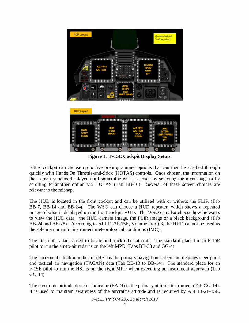
The F-15E Strike Eagle is a dual-role fighter designed to perform air-to-air and air-to-ground missions. An array of avionics and electronics systems gives the F-15E the capability to fight at low altitude, day or night and in all weather. The aircraft uses two crew members, a pilot and a weapon systems officer (WSO). It has the capability to fight its way to a target over long ranges, destroy enemy ground positions and fight its way out. For air-to-ground missions, the F-15E can carry most weapons in the Air Force inventory. It also can be armed with Air Intercept Missile (AIM) 9M Sidewinders or AIM-120 advanced medium range air-to-air missiles for the air-to-air role (Tab CC-12 to CC-13). The F-15E has eight total displays that show pertinent aircraft and sensor data (Tab BB-33). In the front cockpit, there is a head-up display (HUD) that shows relevant flight data and can also show the forward looking infrared (FLIR) image (Tab BB-24). There are seven other screens in the aircraft that can display data. In the front cockpit, the pilot has a left and right multi-purpose display (MPD) and a center multi-purpose color display (MPCD). In the rear cockpit, the WSO has two MPDs, one on the left and one on the right, and two MPCDs, one on the left and one on the right. The MPDs are in the center and the MPCDs are on the periphery (Tab BB-33). The information shown on each of these screens is based on choices that the pilot and WSO make on a menu screen (Tab BB-9). Figure 1 shows both cockpits and the recommended tactical setup of the displays in accordance with Air Force Tactics, Techniques, and Procedures (AFTTP) 3-3.F-15E (Tab BB-33).
F-15E, T/N 90-0235, 28 March 2012 4
Figure 1. F-15E Cockpit Display Setup
Either cockpit can choose up to five preprogrammed options that can then be scrolled through quickly with Hands On Throttle-and-Stick (HOTAS) controls. Once chosen, the information on that screen remains displayed until something else is chosen by selecting the menu page or by scrolling to another option via HOTAS (Tab BB-10). Several of these screen choices are relevant to the mishap. The HUD is located in the front cockpit and can be utilized with or without the FLIR (Tab BB-7, BB-14 and BB-24). The WSO can choose a HUD repeater, which shows a repeated image of what is displayed on the front cockpit HUD. The WSO can also choose how he wants to view the HUD data: the HUD camera image, the FLIR image or a black background (Tab BB-24 and BB-28). According to AFI 11-2F-15E, Volume (Vol) 3, the HUD cannot be used as the sole instrument in instrument meteorological conditions (IMC). The air-to-air radar is used to locate and track other aircraft. The standard place for an F-15E pilot to run the air-to-air radar is on the left MPD (Tabs BB-33 and GG-4). The horizontal situation indicator (HSI) is the primary navigation screen and displays steer point and tactical air navigation (TACAN) data (Tab BB-13 to BB-14). The standard place for an F-15E pilot to run the HSI is on the right MPD when executing an instrument approach (Tab GG-14). The electronic attitude director indicator (EADI) is the primary attitude instrument (Tab GG-14). It is used to maintain awareness of the aircraft’s attitude and is required by AFI 11-2F-15E,
F-15E, T/N 90-0235, 28 March 2012 5
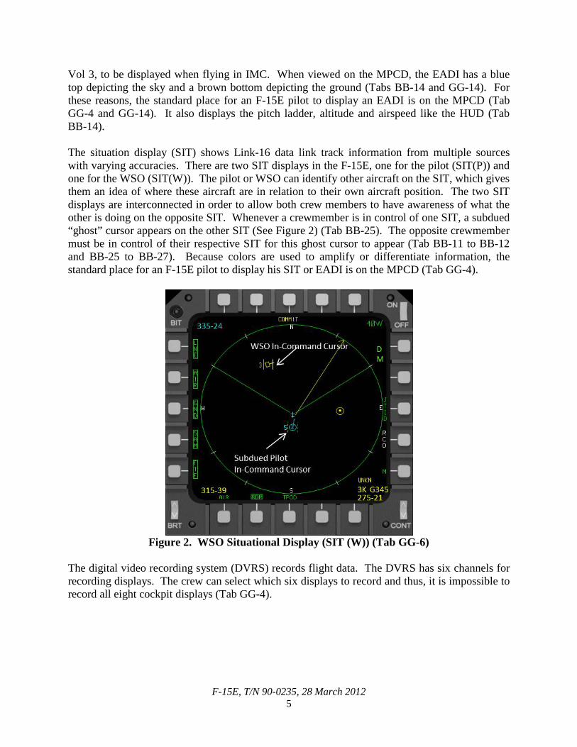
Vol 3, to be displayed when flying in IMC. When viewed on the MPCD, the EADI has a blue top depicting the sky and a brown bottom depicting the ground (Tabs BB-14 and GG-14). For these reasons, the standard place for an F-15E pilot to display an EADI is on the MPCD (Tab GG-4 and GG-14). It also displays the pitch ladder, altitude and airspeed like the HUD (Tab BB-14). The situation display (SIT) shows Link-16 data link track information from multiple sources with varying accuracies. There are two SIT displays in the F-15E, one for the pilot (SIT(P)) and one for the WSO (SIT(W)). The pilot or WSO can identify other aircraft on the SIT, which gives them an idea of where these aircraft are in relation to their own aircraft position. The two SIT displays are interconnected in order to allow both crew members to have awareness of what the other is doing on the opposite SIT. Whenever a crewmember is in control of one SIT, a subdued “ghost” cursor appears on the other SIT (See Figure 2) (Tab BB-25). The opposite crewmember must be in control of their respective SIT for this ghost cursor to appear (Tab BB-11 to BB-12 and BB-25 to BB-27). Because colors are used to amplify or differentiate information, the standard place for an F-15E pilot to display his SIT or EADI is on the MPCD (Tab GG-4).
Figure 2. WSO Situational Display (SIT (W)) (Tab GG-6)
The digital video recording system (DVRS) records flight data. The DVRS has six channels for recording displays. The crew can select which six displays to record and thus, it is impossible to record all eight cockpit displays (Tab GG-4).
F-15E, T/N 90-0235, 28 March 2012 6
4. SEQUENCE OF EVENTS
a. Mission The mishap sortie (MS), flown on Wednesday, 28 March 2012, was a training mission flown as part of a large force exercise (LFE) at a deployed location in Southwest Asia (Tab K-2). The mishap flight (MF) operated in an interdiction role to support exercise objectives (Tab V-6.14). The mission had 27 “Blue Air” aircraft as part of the overall strike package and 8 “Red Air” aircraft opposing the package (Tab V-11.2). The MF consisted of the MA, flown by the MP and the MWSO, as well as the mishap wingman (MW), flown by the mishap wingman pilot (MWA) and the mishap wingman WSO (MWB). The two MF aircraft were the only 391 EFS aircraft that flew during the LFE. This mission was properly authorized by the Top 3 (the on-duty squadron supervisor who acts on behalf of the Director of Operations) (Tabs K-7 and V-4.2).
b. Planning Mission planning for the MS was detailed and accomplished the day prior to the flight. All four MF aircrew attended the mission planning (Tab V-1.29). A 44th Expeditionary Fighter Squadron pilot served as the overall mission commander and coordination with all exercise players occurred at the 380 AEW Air Warfare Center (AWC) (Tab V-1.29 and V-11.2). Mission planning began with an Air Tasking Order fragmentation drop to identify training targets, threats and package assets (Tab V-11.2). Product preparation for the flight was standard and included: an Air Force Form 70 fuel plan, a master target attack card, a flight mission data card and a package data card (Tab GG-3). The 380 AEW Airboss gave a mission coordination brief for all aircrew flying in the LFE which covered pertinent safety-related information including details on the weather call, training rules, recovery plan, instrument approach planning, spatial disorientation over flat featureless terrain and an emphasis on how dark it would be during the recovery phase of flight (Tabs V-2.5 and AA-10 to AA-13). The LFE mission commander’s briefing was in accordance with standards. There was one problem with the altitude deconfliction plan. However, the MF discussed the issue with the other formations immediately after the briefing and resolved the problem (Tab V-3.3). Following these two briefs, the MP briefed the MF using the squadron standard briefing guide (Tab AA-4 to AA-8). The MP’s brief was complete and included all appropriate items in accordance with AFI 11-2F-15E, Vol 3 (Tab V-1.3, V-2.3 and V-3.3).
c. Preflight The MF’s preflight actions were normal and included gathering current weather from 380th Expeditionary Operations Support Squadron (380 EOSS), reviewing the Notices to Airmen, flight crew information files and filing their flight plan (Tabs K-2, K-9 to K-10 and V-2.3). In addition, the MP accomplished an Operational Risk Management (ORM) worksheet (Tab AA-3). The MF inspected and properly signed for their aircrew flight equipment (AFE), including NVGs (Tab H-44 to H-45). They also received a standard Top 3 briefing prior to departing for the aircraft, which consisted of a weather update, jet status, current runway, Navigational Aid (NAVAID) status, diverts and restricted area status (Tabs K-12 and V-1.3). The Top 3 also briefed to expect the NVG illumination to be low due to dust at lower altitudes (Tab V-4.11).
F-15E, T/N 90-0235, 28 March 2012 7
According to AFI 11-214, illumination levels help determine the minimum tactical operating altitude. After arriving at the flight line, the MC had several problems during ground operations. Their initial aircraft was not crew-ready, so after coordination with the production superintendent they stepped to another aircraft. After engine start, that aircraft was found to have an inoperable engine oil sensor forcing the MC to step to the MA (Tab V-1.3). The MA was in a two-tank configuration. It also had a navigation and forward looking infrared (NAV FLIR) pod and a Sniper targeting pod. Additionally, it was armed with 510 rounds of 20 millimeter ammunition, an Air Combat Maneuvering Instrumentation pod and a captive carriage training missile (Tabs J-9 and V-4.4). This delay put the MC slightly behind their briefed take-off time, so the MC cleared the MW to take-off without them (Tab V-1.3). In accordance with squadron standards, the MWSO turned on the DVRS after start-up. Of the eight possible displays, the six that the MC chose to record were the HUD, the front cockpit left MPD (which displayed the air-to-air radar throughout flight) and all four displays in the rear cockpit. Because the front cockpit MPCD and front cockpit right MPD were not recorded, it is impossible to know with absolute certainty what the MP viewed on those two displays throughout flight (Tab GG-4). The rest of ground operations up to take-off were accomplished in accordance with Technical Order (TO) 1F-15E-1-2-1 CL-1 (Dash 1 Checklist), and the MWSO stated that he did not feel rushed (Tab V-1.11). Just prior to take-off, the MWSO asked the MP if he had the FLIR on. The MP then turned on the FLIR and the recorded DVRS HUD display changed accordingly from the HUD camera to NAV FLIR-produced video. From that point forward, the FLIR was on and was recorded by the DVRS. However, there is no way to determine if the MP turned the FLIR contrast and brightness up enough on the HUD control panel to see the generated image on the front cockpit HUD. It is possible to have the FLIR on and recording, yet have the contrast and brightness turned down so low that the FLIR image is not displayed on the front cockpit
HUD. The MC took off prior to sunset, so it is unlikely that the MP was looking at the FLIR image at that time (Tab GG-5). Additionally, the MP never mentioned turning up the FLIR brightness or contrast throughout the rest of the mission (Tab GG-5 to GG-8).
d. Summary of Accident The MC took off at 1444Z and flew southeast into the operating area (OA) as directed by the standard departure procedure (Tabs K-2 to K-3 and GG-5). They proceeded to their holding area as briefed and rejoined with the MW (Tab V-3.3). Despite taking off late, the MC arrived in holding 22 minutes prior to their push time. Push time is when the MF must leave holding enroute to their target area in order to achieve their assigned “time on target.” While on climb during the departure, the MC made several comments expressing concern with the weather, specifically regarding the poor visibility (Tab GG-5). However, the weather call was made as “full-up clear of clouds,” meaning that there was no weather that would affect the mission, and that all mission aircraft must maintain their own visual meteorological conditions (VMC) cloud clearances in accordance with AFI 11-214 night training rules (Tab GG-5). After entering holding in the block 20,000 feet mean sea level (MSL) to 24,000 feet MSL, the MC verbalized putting on their NVGs and did not comment on the weather again (Tab GG-6 to GG-8). Several crews who flew during the LFE reported the weather was clear above about 10,000 feet MSL
F-15E, T/N 90-0235, 28 March 2012 8
with a discernable horizon (Tabs R-7, V-2.9 and V-3.7). Several crews also noted seeing stars above 10,000 feet MSL while on NVGs (Tab V-2.10 and V-3.7). At push time, the MC did not know the exact location of the aircraft they planned to follow into the target area (Tab GG-6). After a short period, the MC positively identified the flight they were supposed to be following on the SIT and pushed behind them on time (Tab V-3.3). It appeared the MP used the SIT a majority of the time for deconfliction, only relying on radar and visual cues as a back-up (Tab GG-6). The MF dropped their training weapons successfully and egressed the target area uneventfully (Tabs V-1.9 and GG-6). The MF did not have any air-to-air engagements during the mission (Tab V-3.4). During target egress, the MP identified a potential deconfliction issue with other package aircraft and used the SIT along with NVGs to establish deconfliction (Tabs V-1.3 and GG-6). This deviation from the plan worried the MF and elevated their concern about the potential for breakdowns in the deconfliction plan (Tab V-1.19). Once clear of these aircraft, the MF reestablished itself in holding and remained there to burn fuel and to await their assigned recovery time. While in holding, the MC had a brief discussion about how to fly the recovery and then contacted the Air Traffic Control (ATC) agency for approach instructions (Tab GG-7). At 1552Z, the MP called for the MF to take off their NVGs and the MC did so (Tab GG-7). The MW left their NVGs until they were established in the descent due to concerns about deconfliction on the recovery (Tab V-2.3). Then the MF began their recovery back to the deployed location (Tab GG-7). ATC initially directed the MF to maintain an arc 20 NM from the TACAN, a navigation aid used to fly the instrument approach. The 20 NM arc is non-standard for the recovery because the published approach is via the 17 NM arc (Tabs K-5 and GG-7). As the MP turned to maintain the 20 NM arc, the MWSO questioned this action. The MP told him that ATC had instructed this change to the recovery procedure. At that same time, ATC cleared the MF to 5,000 feet MSL. As the MP leveled the MA at 5,000 feet MSL, ATC directed them onto the 17 NM arc and cleared them to 4,000 feet MSL. The MP made two turns of approximately 45 degrees of bank to establish the MA on the 17 NM arc while descending to 4,000 feet MSL (Tab GG-7). The MP accurately maintained his relationship with regard to the TACAN station on both the 20 and 17 NM arcs (Tabs M-2 and GG-7). The MP likely had an HSI displayed on his right MPD because it would be difficult to maintain position on an arc without having an HSI displayed and pilots typically run the HSI on the right MPD (Tab GG-7 and GG-14). The MP had just established the MA on the 17 NM arc at 4,000 feet MSL when ATC cleared him to 3,000 feet MSL (Tabs N-2 and GG-7). He responded to ATC with a correct read-back of the instructions and began a steady five degree nose low descent in a wings-level attitude (Tab GG-7). At approximately 3,400 feet MSL, the ATC controller queried the MP if he was “radar contact” with the aircraft in front of him on the arc passing the 270 degree radial. The MP replied affirmatively to ATC that he had radar contact, and the controller cleared him to descend to 2,000 feet MSL behind that aircraft (Tab N-3). In reality, the MP did not use the radar to gain situational awareness on the aircraft’s location. Instead, he took control of and used the SIT(P) for this purpose. Based on this information and because the MA was in a descent, the aircraft in front of him would have appeared slightly above him and ten degrees left of the MA’s midline (Tab GG-7).

F-15E, T/N 90-0235, 28 March 2012 9
From 16:03:03Z until 16:03:10Z, the MP was in control of and actively moving his cursor on the SIT. All evidence suggests the MP was using the SIT(P) on the MPCD rather than viewing an EADI (Tab GG-7). As the MA passed through 3,100 feet MSL, the MP pulsed the stick backwards and forwards. This caused a quick pitch up and then a pitch down of the MA (Tabs V-1.4 and GG-7). The MP simultaneously pushed the throttles forward from less than full power to full afterburner for two seconds. The MP then aggressively pushed the stick forward, inducing -2.6 gravitational force (g) on the MA (Tab J-3). Next, the MP expressed verbal concern about what was going on around him, pulled the throttles back to less than full power and rolled the MA left, dwelling about one second in approximately 70 degrees of left bank and 20 degrees nose low (Tabs J-3 and GG-7). The MWSO was not sure which way the jet rolled and did not tell the MP to recover because he worried that any input on his part might have made the situation worse (Tab V-1.16). The MP expressed further concern as he continued to roll another 110 degrees left to a fully inverted position approximately 1,800 feet AGL and 25 degrees nose low (Tabs J-3 and GG-7 to GG-8). At that point, the MWSO believed that the MP did not know which way was up (Tab V-1.4). The MWSO grabbed the controls and rolled the MA left towards a near wings-level position (Tabs J-3 and V-1.4). The ground collision warning system went off at that time, giving the MC an arrow on all of the displays, including the HUD, indicating the fastest way to pull to the horizon (Tabs BB-4 to BB-6 and GG-8). The MWSO then pulled 11 g while rolling left to wings-level (Tabs J-11 and V-1.4). The final frame of HUD footage on the DVRS displayed the MA had a positive vector away from the ground and a radar altimeter reading of 88 feet above ground level (AGL) (Tab GG-8). As the MWSO rolled the MA to nearly level flight, he initiated ejection for the MC at 16:03:23Z (Tabs H-13, V-1.4 and GG-8). The MA airspeed read 352 knots in the last frame of the HUD video (Tab GG-8). Had a radio tower not been in the flight path, the MA would have recovered prior to impacting the ground (Tab J-8 and J-11). The time from the first abrupt maneuver and verbal concern by the MP to the time of ejection was approximately 11 seconds (Tab GG-8).
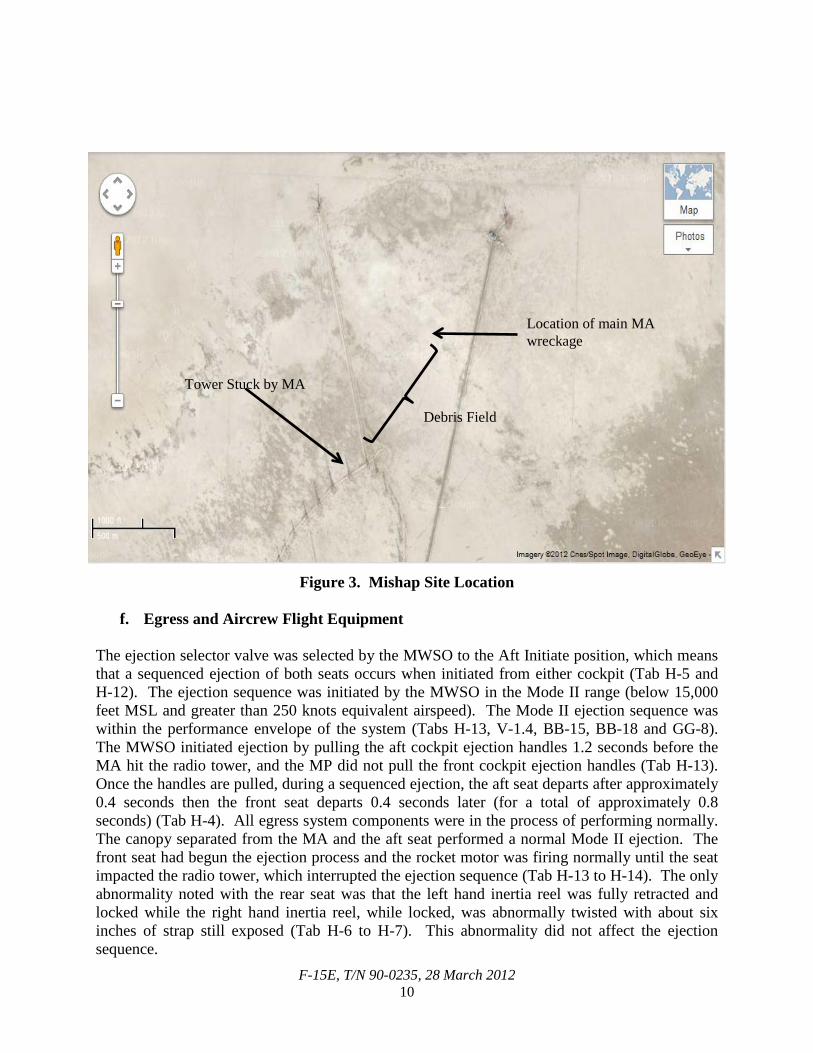
e. Impact The MA impacted the terrain at approximately 16:03:30Z about 18 NM west, southwest of the deployed location in Southwest Asia (Tabs H-2 and GG-8). The MA was in the same configuration at impact as it was prior to take-off (Tab GG-8). The MA struck a 377-foot tall radio tower and crashed approximately 0.5 NM northeast of the tower (Tab H-2). Based on the damage to the MA, it appears the right wing of the MA struck the radio tower (Tab J-3). The impacted radio tower was part of a large tower array just north of a major east-west running well-trafficked highway (Tab J-64).
F-15E, T/N 90-0235, 28 March 2012 10
Figure 3. Mishap Site Location
f. Egress and Aircrew Flight Equipment The ejection selector valve was selected by the MWSO to the Aft Initiate position, which means that a sequenced ejection of both seats occurs when initiated from either cockpit (Tab H-5 and H-12). The ejection sequence was initiated by the MWSO in the Mode II range (below 15,000 feet MSL and greater than 250 knots equivalent airspeed). The Mode II ejection sequence was within the performance envelope of the system (Tabs H-13, V-1.4, BB-15, BB-18 and GG-8). The MWSO initiated ejection by pulling the aft cockpit ejection handles 1.2 seconds before the MA hit the radio tower, and the MP did not pull the front cockpit ejection handles (Tab H-13). Once the handles are pulled, during a sequenced ejection, the aft seat departs after approximately 0.4 seconds then the front seat departs 0.4 seconds later (for a total of approximately 0.8 seconds) (Tab H-4). All egress system components were in the process of performing normally. The canopy separated from the MA and the aft seat performed a normal Mode II ejection. The front seat had begun the ejection process and the rocket motor was firing normally until the seat impacted the radio tower, which interrupted the ejection sequence (Tab H-13 to H-14). The only abnormality noted with the rear seat was that the left hand inertia reel was fully retracted and locked while the right hand inertia reel, while locked, was abnormally twisted with about six inches of strap still exposed (Tab H-6 to H-7). This abnormality did not affect the ejection sequence.
Tower Stuck by MA
Location of main MA wreckage
Debris Field
F-15E, T/N 90-0235, 28 March 2012 11
A thorough review of the AFE inspection and maintenance records revealed no discrepancies. The MWSO’s equipment was recovered and the Global Positioning System (GPS) and signal mirror were damaged during the ejection (Tab H-21). All survival equipment, including the personnel locator beacons, appeared to have functioned properly (Tab H-11 to H-13). The MWSO successfully used his survival radio and night flare during the recovery effort (Tabs H-21 and V-1.4).
g. Search and Rescue The MW was in two NM radar-assisted trail at the time of the mishap. Just prior to seeing the blast from the ejection seats and the fireball of the impact, MWA commented that the MA was maneuvering abnormally. After witnessing the impact, MWA initially tried to raise the MC on their discrete radio frequency but did not get a response. MWB stated he thought the MA had been involved in a mid-air collision, to which MWA replied he thought the MA may have hit a tower. The MW then determined the coordinates of the crash site, set a new minimum fuel to return to base and began on-scene commander duties (Tab GG-8). The MW was the origin of the first rescue call when they alerted ATC at approximately 1604Z that there had been a possible mid-air and that they were orbiting present position at 3,000 feet MSL (Tabs N-3 to N-4 and GG-8). ATC deconflicted all other traffic above the MW and continued to sequence the recovery of aircraft that participated in the LFE. After ensuring deconfliction, ATC queried the MW if he was requesting search and rescue (SAR) assets, and the MW responded that there had been a possible collision with the ground. ATC then directed the MW onto a separate frequency to begin the SAR effort (Tab N-4). At 1616Z, ATC passed initial crash information to the control tower at the deployed location. At 1628Z, ATC confirmed that there had been a crash (Tab II-4). At 1632Z, the deployed location airfield management operations initiated their Quick Reaction Checklist Number Two to assemble SAR assets for an off-base aircraft mishap (Tab II-3). Meanwhile, the MW contacted the 391 EFS operations desk and alerted the Top 3 that the MA had crashed (Tab GG-8). The Top 3 alerted the 391 EFS/DO, who immediately took charge of the situation and instituted a squadron recall (Tab V-4.3). When he arrived, the 391 EFS/CC took charge and sequestered recalled squadron personnel in a ready room until more information was available (Tab V-5.3). The 391 FS/DO and Top 3 continued to communicate with the MW (Tab V-4.3). The MW passed coordinates to ATC and the Top 3, but stated that they were unable to identify any chutes in the air or on the ground. The MW maintained sensors on the crash site and continued to search for survivors (Tab V-3.4). HN SAR helicopters were scrambled to the location at 1635Z (Tab II-4). While coordinating the rescue effort, the MW heard the MWSO over the Guard frequency and established communication with the MWSO at 1617Z. The MWSO relayed he was ambulatory (Tab GG-8). The MWSO described his position to the MW and they directed him to walk west to a nearby road (Tab V-3.4). In an effort to contact the MP, the MWSO used his night flare (Tabs V-1.4 and GG-8). The MW was able to identify the flare through their NVGs but could not precisely locate the MWSO with their aircraft sensors (Tab V-3.4 to V-3.5). The first recovery aircraft, a HN SAR helicopter, experienced a hard landing at the mishap site due to brown out conditions and was unfit for further flight (Tabs R-16 and V-1.5). A United States (U.S.) helicopter operating nearby offered to help the recovery effort and flew to the crash

F-15E, T/N 90-0235, 28 March 2012 12
site (Tabs V-1.5, V-4.4 and GG-8). The MW communicated the mishap site coordinates directly with the U.S. helicopter. The U.S. helicopter used the MW as a relay with the MWSO until 1636Z, when the U.S. helicopter confirmed two-way communications with the MWSO. The MW reached minimum fuel at 1637Z, and returned to base uneventfully (Tabs V-3.5 and GG-8). The U.S. helicopter landed at the crash site shortly thereafter (Tab V-1.5). A second HN SAR helicopter arrived at the crash site at 1708Z (Tab II-4). The U.S. and HN forces found and medically evaluated the MWSO. They also searched for and found the MP’s remains (Tab V-1.5). The initial assembly of the response convoy was at 1713Z (Tab FF-3). This convoy, consisting of U.S. explosive ordnance disposal, medical and fire department personnel and HN security forces, left the deployed location at 1720Z. They arrived at the mishap site at approximately 1811Z just as the U.S. helicopter was leaving the scene with the MWSO (Tabs V-12.3 and FF-3). The U.S. helicopter landed at the deployed location with the MWSO at 1829Z (Tab II-3). The 391 EFS/CC met the MWSO upon landing and the MWSO was taken by ambulance to the base hospital for a medical evaluation (Tab V-5.5). U.S. security forces arrived at the mishap site at approximately 1841Z (Tab V-12.3). One of the first responder crash vehicles could not operate on the sand, which slightly delayed rescue efforts (Tab FF-3). Emergency responders continued to work throughout the night until 1025Z on 29 March 2012 (Tab FF-3).
h. Recovery of Remains U.S. and HN personnel located the MP’s remains approximately 50 yards away from the downed tower and worked together to recover the MP (Tab V-12.3). The MP was transported by HN helicopter from the crash site to the deployed location (Tab FF-4). The helicopter landed at 2025Z and was met by USAF personnel, who received the MP into their care (Tabs FF-4 and II-3). 5. MAINTENANCE
a. Forms Documentation The Air Force Technical Order (AFTO) 781 series forms and Integrated Maintenance Data System (IMDS) along with Time Compliance Technical Orders (TCTO) document all maintenance and provide a complete record of inspections, servicing, configuration, status and flight records related to a specific aircraft (Tab U-3). A complete review of active AFTO 781 series aircraft maintenance forms revealed no discrepancies indicating malfunctioning engines, flight controls or hydraulic components on the MA relevant to the mishap. A detailed review of AFTO 781 historical records (pulled forms) for the time period 90 days preceding the mishap revealed no evidence of mechanical, structural or electrical discrepancies (Tab U-3). A thorough review of IMDS historical records prior to the mishap and review of all TCTOs revealed one maintenance issue relevant to the mishap, addressed below in paragraph 5f (Tab U-3).
F-15E, T/N 90-0235, 28 March 2012 13
b. Inspections A 400-hour phase inspection is accomplished by highly trained crew chiefs and specialists to inspect the aircraft components and airframe for damage, structural integrity and correct systems operation. The MA had accumulated 378.3 hours since the last scheduled 400-hour inspection and was current at the time of the mishap (Tab D-2). In accordance with TO 00-20-1, a Basic Post Flight (BPO) inspection is required to be performed on the aircraft upon the final flight of the day and a preflight (PR) inspection is required to be performed within 72 hours of the next flight. A timely combined BPO/PR inspection was accomplished on 27 March 2012 at 1700Z. A qualified production superintendent accomplished and signed an Exceptional Release, which serves as a certification that the active forms were reviewed, ensuring the aircraft is safe for flight (Tab D-4). The total operating hours for Engine #1 was 6,527.4 and it had accumulated 87.1 hours since its last overhaul. It was installed in the MA on 9 February 2012. The total operating hours for Engine #2 was 6,165.2 and it had accumulated 185.0 hours since its last overhaul. It was installed in the MA on 21 December 2011 (Tab D-2). Each engine is due a borescope inspection every 100 hours and was current on both engines at the time of the mishap (Tab D-11 and D-17 to D-18).
c. Maintenance Procedures A review of the MA’s AFTO 781 series forms and IMDS revealed all maintenance actions on the MA were accomplished in compliance with standard approved maintenance procedures and technical orders (Tab U-3). There is no evidence that maintenance procedures were relevant to the mishap.
d. Maintenance Personnel and Supervision A review of the applicable 391st Expeditionary Maintenance Squadron log books and training records revealed no discrepancies with maintenance personnel or supervision. All personnel were qualified, adequately trained and properly supervised (Tab U-3 to U-4).
e. Fuel, Hydraulic and Oil Inspection Analyses Analysis of the hydraulic and oil servicing carts used on the MA were found to be clean (Tab D-53 to D-61). Fuel truck and fuel storage area samples were taken and analyzed and were also found to be clean (Tab D-66 to D-69). Airframe Mounted Accessories Drive and Constant Speed Drive samples recovered from the MA contained a solid that appeared to be sand, likely due to the MA impacting desert terrain, and is not deemed relevant to the mishap (Tab D-62 to D-63). All other samples taken from the MA were found to be clean (Tab D-51 to D-52 and D-64 to D-65).
F-15E, T/N 90-0235, 28 March 2012 14
f. Unscheduled Maintenance Review of AFTO 781 series forms and IMDS revealed that the MA was impounded the day prior to the mishap because of a missing blue mechanical pencil. All of the appropriate individuals were informed of the aircraft impound (Tab D-83 to D-86). Maintenance actions performed for the Foreign Object Damage (FOD) recovery included: FOD inspection and borescope of the forward and aft cockpits, removal of the forward and aft ejection seats, removal of the canopy, removal of the left and right Angle of Attack probes and removal of panels to conduct a thorough search (Tab D-36 to D-49 and D-83 to D-86). The pencil was found in the cockpit of another aircraft that was aborted earlier that day and verified by the pilot who lost the pencil (Tab V-9.8). Neither the FOD nor impound maintenance were relevant to the mishap. Further review of AFTO 781 series forms and IMDS revealed that the MA had a four-time occurrence of pilot-reported discrepancies for the front cockpit Vertical Speed Indicator (VSI) from 21 February 2012 to 27 March 2012, which was the last sortie prior to the mishap (Tab U-3). Several maintenance actions taken to repair the VSI included: replacing the VSI, replacing the relay that supplies power to the indicator, replacing the right Air Data Processor (ADP) which electrically drives the indicator needle and checking the wiring to the right ADP. All of the above steps were appropriate corrective maintenance actions (Tab J-65 to J-66). The day prior to the MS, the VSI was replaced for a second time and it is unlikely this action fixed the problem since the VSI had already been changed earlier in the troubleshooting process (Tabs D-35 and J-66). Some parts related to the VSI system were not recovered from the mishap site and those parts that were recovered were not able to be tested due to sustained damage (Tabs J-6 to J-7 and U-5 to U-7). Therefore, it cannot be determined whether the VSI was operational at the time of the mishap.
6. AIRCRAFT AND AIRFRAME
a. Condition of Systems and Structures
Due to the MA’s collision with the radio tower, impact with the ground and post-crash fire, many parts were badly damaged or unrecoverable. None of the parts recovered and tested showed any indication of a malfunction, nor is there any indication that the pre-crash condition of any of the aircraft systems and structures was a factor in the mishap (Tabs J-3 to J-8 and H-11 to H-14).
b. Repair and Testing Stations
(1) Flight Control Components
The relevant primary flight control parts that were recovered were submitted to Boeing for analysis. Numerous tests were performed to determine functionality (Tab J-7 and J-29 to J-48). The following control stick components were subjected to physical testing and investigation: forward and aft stick force sensors, lateral and longitudinal feel/trim actuators and lateral control system damper (Tab J-7). No failures or abnormalities were discovered and all control stick components were determined to be functioning properly at the time of impact (Tab J-29 to J-39).
F-15E, T/N 90-0235, 28 March 2012 15
The following hydraulic components were subjected to physical testing and investigation: left and right stabilator actuators, left and right aileron actuators, Pitch Roll Channel Assembly (PRCA) and Aileron Rudder Interconnect (ARI) (Tab J-7). A visual inspection was conducted on the actuators and there was no evidence to indicate these components were working improperly at the time of the impact. The PRCA and ARI were torn down and visually inspected due to their complex inner workings. Based on physical observations and Standard Flight Data Recorder (SFDR) data, these components were determined to be functioning properly (Tab J-40 to J-48).
(2) Maintenance Data Transfer Module (DTM)
The maintenance DTM was sent to Boeing for testing, but was too damaged for data recovery (Tab J-7). This was not determined to be a factor related to the mishap.
(3) Electromagnetic Interference (EMI)
Boeing also investigated the potential for electromagnetic environmental effects from the high frequency (HF) radio towers interfering with the MA. Scientific analysis of the HF radio tower array, coupled with factual information provided by the chief engineer of the facility, revealed that the chance of the mishap being related to an excessive external radio frequency was very low (Tab J-49 to J-51). The Warner Robins-Air Logistics Center also investigated the potential for EMI affecting flight controls. There was no recorded audio from the MC that they were experiencing any EMI, there were no indications of EMI on the displays and no anomalies in the recorded flight data (Tab J-66).
(4) Engine #1 and Engine #2, F100-PW-229
The Digital Electronic Engine Controller (DEEC) and Engine Diagnostic Unit (EDU) for Engine #1 were sent to Pratt & Whitney (P&W) and Hamilton Sundstrand (HS) for download and investigation. Faults download by the DEEC were consistent with engine faults resulting from a crash. There is no evidence that the faults were set prior to the mishap (Tab J-55). The EDU was severely damaged due to the crash. However, the EDU memory chips were still intact, but most of the faults/usual data stored in the memory were missing. P&W and HS were not able to determine the cause of the memory loss (Tab J-56). The components for Engine #2 were not able to be tested due to damage sustained from the crash (Tab U-8). There is no evidence to suggest the MA’s engines were a factor in the mishap.
(5) Standard Flight Data Recorder (SFDR) and Crash Survivable Memory Unit (CSMU)
SFDR data is written to the CSMU, which has sufficient memory to record the last 15 minutes of flight data. The CSMU was recovered from the MA and was sent to Boeing for review and a
F-15E, T/N 90-0235, 28 March 2012 16
detailed analysis (Tab J-9 and J-66). Boeing concluded that the collected SFDR data displayed no evidence of uncommanded flight control movement (Tab J-8 to J-13).
(6) Egress Analysis
The egress system components were sent to the Ogden Air Logistics Center and were evaluated and tested in great detail by egress equipment specialists to determine proper operation. Investigation and inspection of the egress system revealed the forward and aft ejection seats were functioning properly at the time of impact with the radio tower (Tab H-2 to H-14).
c. Functionality of Equipment
All MA parts tested were determined to be functioning and in proper working order at the time of the mishap (Tabs J-6 to J-8 and H-2 to H-14). 7. WEATHER
a. Forecast Weather The 380 EOSS Weather Flight provided the mission execution forecast on 28 March 2012 (Tab F-2). Surface winds at the deployed location were expected to be from the southeast at 15 knots gusting to 25 knots with a temperature of 31 degrees Celsius. Anticipated take-off visibility was 4,000 meters and blowing dust with few clouds at 11,000 feet AGL. The forecasted hazards included winds greater than 25 knots and blowing dust with less than 2,000 meters visibility (Tab F-2 to F-3). The following NVG data was also provided: the sunset was at 1436Z and the end of civil twilight was at 1459Z; the moonrise was at 0548Z and the moonset was at 1937Z (Tab F-2). The moon was waxing and was located on an azimuth of 277 degrees true with an elevation of 45 degrees above the horizon. It was 30% full. Based on moon data alone the 380 EOSS assessed the NVG illumination as high at 9.93 millilux (Tab F-7).
b. Observed Weather At the time of the mishap, raw weather data observations at the deployed location were southeasterly winds at 9 knots, visibility greater than 9,999 meters and clear skies (Tab F-7). During the step brief, the Top 3 briefed the crews that visibility and NVG illumination could be low, especially at low altitude (Tab V-4.11). Several crews reported that the skies were clear of clouds in the OA and that there was a discernable horizon with NVGs above 10,000 feet MSL (Tab V-2.7 and V-4.10). Multiple aircrew members also reported the actual conditions on recovery back to base were very dark and that no discernable horizon existed due to blowing dust (with or without NVGs) (Tabs F-6, R-6, V-2.9 and V-4.10). Post-mishap weather observations from the ground reported clear skies with some scattered clouds and good visibility throughout the SAR effort (Tab V-12.2).
c. Space Environment Not applicable.
F-15E, T/N 90-0235, 28 March 2012 17
d. Operations On the day of the mishap, the first period of flying was cancelled because the visibility at the primary divert bases was below USAF minimums in accordance with AFI 11-202, Vol 3 (Tab V-10.2 and V-10.5). The Top 3 did not cancel the second period of flying because the weather had improved (Tab V-4.11 and V-10.5). The mission weather call was “full up clear of clouds” (Tab GG-5). 8. CREW QUALIFICATIONS
a. Mishap Pilot Training
The MP was a fully qualified combat mission ready (CMR) F-15E two-ship flight lead (Tab G-2). All necessary flight currencies were up-to-date and all required training for the planned mission was current in accordance with AFI 11-2F-15E, Vol 1 (Tab T-10 to T-18). The MP completed his most recent mission qualification in the F-15E on 11 January 2011, which also fulfilled his initial CMR qualification. The MP completed his most recent instrument qualification in the F-15E on 2 August 2011 (Tab G-13). In accordance with the F-15E ready aircrew program (RAP) tasking memorandum, AS-12, for an experienced CMR pilot to remain current, he must fly 8 sorties in the last 30 days (a one month look-back) and 24 sorties within 90 days (a three month look-back). The MP was placed on probation on 29 September 2011 due to not meeting one month or three month look-back requirements in September due to limited aircraft availability (Tab T-8). He was subsequently placed on regression on 3 November 2011 due to not meeting look-back requirements again in October (Tab T-9). In accordance with AFI 11-2F-15E, Vol 1, the squadron commander has the option to allow a member who does not meet look-back requirements to remain CMR and place them on a one month probationary status. The member must then meet one month look-back requirements to remain CMR; otherwise, they are placed on regression and must complete requalification sorties in addition to meeting one month look-back to regain CMR status. The MP reclaimed CMR status in November 2011 by accomplishing two requalification sorties, in addition to meeting the one month sortie look-back requirement (Tab T-9). The MP completed his two-ship flight lead upgrade on 5 January 2012 (Tab T-5). Training preparation for all 391 EFS aircrew, including the MP, began prior to arrival at the deployed location. This included a spin-up program to get the squadron ready to deploy, with multiple different sortie profiles that were relevant to the Southwest Asia area of responsibility (AOR). The spin-up required a minimum of three night sorties be flown prior to deployment (Tab V-7.8). The MP flew these sorties on 24 January 2012, 25 January 2012 and 8 February 2012 (Tabs T-23, V-7.5 and V-7.8).
b. Mishap Pilot Experience The MP was a great pilot and was highly regarded within the squadron (Tab V-1.9). The MP held a “Pilot” aeronautical rating with 1,462.6 hours of military flying time (Tab G-8). Of this total, the MP had 48.6 hours of total night flight time. The MP had 310.2 hours of primary F-15E time, of which 33.5 hours were at night and 28.7 were on NVGs (Tab G-7). Due to his prior T-37 and T-6 instructor time, the MP was considered “experienced” in accordance with AFI 11-2F-15E, Vol 1 (Tab G-2). The MP had flown 12 total night sorties and one night simulator since arriving at the 391 FS on 1 October 2010 (Tab T-19 to T-24). Prior to the
F-15E, T/N 90-0235, 28 March 2012 18
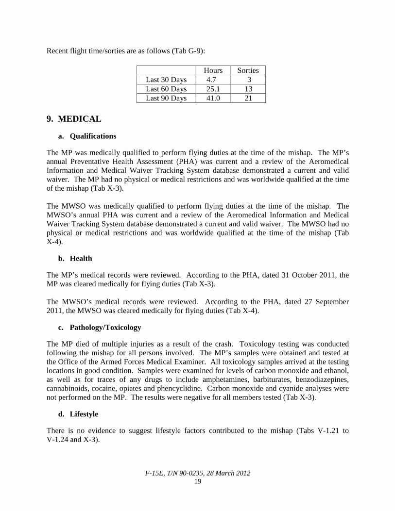
mishap, the MP’s most recent night sortie was flown on 14 March 2012 as part of the squadron deployment. The MP’s total night flight time could raise a concern with his competency and comfort level of flying at night. However, the MP’s leadership had no concerns with his flying abilities, either during the day or at night. Based on the fact that the MP was a two-ship flight lead and a previous First Assignment Instructor Pilot, the 391 FS/CC and 391 FS/DO were confident in the MP’s abilities to complete this mission (Tab V-5.10 to V-5.11 and V-6.13 to V-6.14). The MP flew his previous sortie on 23 March 2012, five days prior to the mishap. The MS was his second sortie and first night sortie at the deployed location (Tab T-24). Recent flight time/sorties are as follows (Tab G-4):
Hours Sorties Last 30 Days 23.0 5 Last 60 Days 41.1 15 Last 90 Days 54.1 22
c. Mishap Weapon Systems Officer Training
The MWSO is a fully qualified CMR F-15E WSO. He was on probation at the time of the mishap for not meeting look-back requirements (Tab G-3). In accordance with the F-15E RAP tasking memorandum, AS-12, the minimum one month look-back for an inexperienced CMR WSO is 9 sorties, and the three month look-back is 27 sorties. The MWSO was on probation because as of 1 March 2012, he did not meet one month or three month look-back criteria, but was still fully qualified to fly the MS (Tab G-3). All other necessary flight currencies were up-to-date and all required training for the planned mission was current in accordance with AFI 11-2F-15E, Vol 1 (Tab T-28 to T-35). The MWSO completed his most recent mission qualification on 8 September 2011, which also fulfilled his initial CMR qualification (Tabs G-14 and T-25). The MWSO flew his three night spin-up sorties on 24 January 2012, 7 February 2012 and 8 February 2012 (Tabs T-39, V-7.5 and V-7.8).
d. Mishap Weapon Systems Officer Experience The MWSO holds a “Combat Systems Officer” aeronautical rating with 213.2 hours of military flying time prior to the mishap. Of this total, the MWSO had 28.7 hours of total night flight time. At the time of the mishap, the MWSO had 188.9 hours of primary F-15E time, of which 27.2 hours were at night and 22.9 were on NVGs (Tab G-12). Because the MWSO had less than 500 hours of primary aircraft flight time at the time of the mishap, he did not meet “experienced” criteria in accordance with AFI 11-2F-15E, Vol 1, but was still fully qualified to fly the MS (Tab G-3). The MWSO had flown eight total night sorties and one night simulator since arriving at the 391 FS on 27 June 2011 (Tab T-36 to T-40). Prior to the mishap, the MWSO’s most recent night sortie was flown on 14 February 2012 (Tab T-39). The MWSO flew his latest sortie on 22 March 2012, six days prior to the mishap (Tab G-12). The MS was his second sortie and first night sortie at the deployed location (Tabs T-39 and V-1.2).
F-15E, T/N 90-0235, 28 March 2012 19
Recent flight time/sorties are as follows (Tab G-9):
Hours Sorties Last 30 Days 4.7 3 Last 60 Days 25.1 13 Last 90 Days 41.0 21
9. MEDICAL
a. Qualifications
The MP was medically qualified to perform flying duties at the time of the mishap. The MP’s annual Preventative Health Assessment (PHA) was current and a review of the Aeromedical Information and Medical Waiver Tracking System database demonstrated a current and valid waiver. The MP had no physical or medical restrictions and was worldwide qualified at the time of the mishap (Tab X-3). The MWSO was medically qualified to perform flying duties at the time of the mishap. The MWSO’s annual PHA was current and a review of the Aeromedical Information and Medical Waiver Tracking System database demonstrated a current and valid waiver. The MWSO had no physical or medical restrictions and was worldwide qualified at the time of the mishap (Tab X-4).
b. Health
The MP’s medical records were reviewed. According to the PHA, dated 31 October 2011, the MP was cleared medically for flying duties (Tab X-3). The MWSO’s medical records were reviewed. According to the PHA, dated 27 September 2011, the MWSO was cleared medically for flying duties (Tab X-4).
c. Pathology/Toxicology
The MP died of multiple injuries as a result of the crash. Toxicology testing was conducted following the mishap for all persons involved. The MP’s samples were obtained and tested at the Office of the Armed Forces Medical Examiner. All toxicology samples arrived at the testing locations in good condition. Samples were examined for levels of carbon monoxide and ethanol, as well as for traces of any drugs to include amphetamines, barbiturates, benzodiazepines, cannabinoids, cocaine, opiates and phencyclidine. Carbon monoxide and cyanide analyses were not performed on the MP. The results were negative for all members tested (Tab X-3).
d. Lifestyle
There is no evidence to suggest lifestyle factors contributed to the mishap (Tabs V-1.21 to V-1.24 and X-3).
F-15E, T/N 90-0235, 28 March 2012 20
e. Crew Rest and Crew Duty Time
All aircrew are required to have proper crew rest prior to performing flying duties as outlined in AFI 11-202, Vol 3. Proper crew rest is defined as a minimum of a 12-hour non-duty period before the designated flight duty period begins. During this time, an aircrew member may participate in meals, transportation or rest as long as he or she has had at least 10 hours of continuous restful activity with an opportunity for at least 8 hours of uninterrupted sleep. The MP demonstrated no abnormalities the night prior to the mishap and was perceived to be well rested on the day of the mishap (Tabs V-1.24 and X-3). The MWSO demonstrated no abnormalities and was well rested on the day of the mishap (Tab V-1.21). 10. OPERATIONS AND SUPERVISION
a. Operations
The 391 EFS aircraft arrived at the deployed location in Southwest Asia on 18 March 2012 (Tab T-24). Upon arrival at the deployed location the aircrew received a safety brief on local approach procedures and a local area orientation (LAO) brief (Tab V-4.6). During these briefings given by the 380 AEW, it was stressed that it would be very dark with very little to no discernable horizon or cultural lighting on the recovery to base at night (Tab V-4.8). In addition to these briefs, the squadron conducted its own LAO brief and a night phase brief to ensure aircrew were ready for day and night operations at the deployed location (Tab V-2.5). The 391 EFS discussed the individual approaches during their briefings and highlighted that there might not be a discernable horizon due to the lack of cultural lighting (Tab V-4.8). However, they did not discuss how to mitigate the lack of visual cues and the potential for disorientation via in-cockpit display setup (Tab V-2.6). All completed briefing and training requirements were documented on an individual AOR checklist signed by the 391 EFS/CC. The MP and the MWSO had completed their checklists (Tab T-7 and T-27). The squadron established operations at the deployed location and were working approximately 10 to 12-hour days setting up and studying everything required to ensure success (Tab V-1.2 and V-6.14). Soon after the squadron had settled in, a HN exercise began which introduced more procedures to study (Tab V-7.8 to V-7.9). The operations tempo was described as high but normal for a deployed fighter squadron and multiple aircrew reported they had a proper amount of time to prepare for each mission (Tab V-7.9, V-8.7 and V-9.6).
b. Supervision Operations supervision for the 391 EFS was appropriate, fully engaged and in accordance with AFI 11-418. The flight authorization process was properly reviewed and approved by the Top 3 (Tab K-7). Additionally, the 391 EFS had an active ORM program at the time of the mishap. The MC self-assessed their participation in the MS as “Moderate Risk” with an overall score of 8 (a score greater than or equal to 14 is considered high). The highest risk factors for the MS were: the complex mission type (LFE), night operations and the probation status of the MWSO. This ORM score required the Top 3’s signature, and the Top 3 signed off the ORM matrix (Tab AA-
F-15E, T/N 90-0235, 28 March 2012 21
3). The Top 3 was available during the mission and was active in the initial mishap reporting and recovery effort (Tab V-4.2 to V-4.5).
11. HUMAN FACTORS
AFI 91-204, Safety Investigations and Reports, Attachment 5, contains the Department of Defense Human Factors Analysis and Classification System which lists potential human factors that can play a role in aircraft mishaps. The following human factors were relevant to this mishap:
a. Spatial Disorientation (Type 2) Recognized
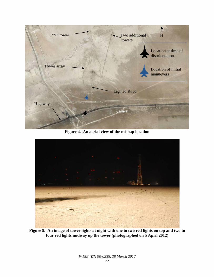
Spatial Disorientation is a failure to correctly sense a position, motion or attitude of the aircraft or of oneself within the fixed coordinate system provided by the surface of the earth and the gravitational vertical. Spatial Disorientation (Type 2) is a factor when recognized perceptual confusion is induced through one or more of the following senses: visual; vestibular; auditory; tactile; proprioception or kinesthetic. Proper control inputs are still possible. The MP became spatially disoriented (Type 2) due to a visual illusion. As the MC was flying the approach back to base, the MP may have focused on lights that appeared from a nearby radio tower array and highway. In an environment devoid of traditional visual cues, most notably the lack of a true horizon, the MP may have relied solely on the lights and incorrectly inverted the MA. It is unknown which specific image caused the MP’s disorientation, but the MP’s maneuvers demonstrate that he believed the MA was inverted and five degrees nose low (Tabs GG-12 to GG-13 and HH-3 to HH-5). Witnesses described the night of the mishap as very dark with no discernable horizon. Additionally, the MP was briefed that the recovery arc would be dark with no cultural lighting. There were no discussions pertaining to highway lights or radio towers (Tab V-1.14 and V-3.9). The mishap occurred at an isolated radio tower array 18 NM west, southwest of the base (See Figure 4). This array forms a horseshoe shape and consists of 31 primary towers. These towers are of varying heights with the tallest being 377 feet in height (Tab Z-3). Each radio tower contains one or two closely spaced steady red lights at the top of the tower and two to four steady red lights at the midpoint (See Figure 5) (Tab EE-3 to EE-4). There is one distinct “Y” shaped tower 1,403.31 meters to the north of the main tower array (Tab Z-3). Directly east of this tower are two additional towers with buildings at their base. There are several buildings in the center of the tower array, which all have white security lights. A lighted road leads out of the horseshoe south towards a major east-west running well-trafficked highway (See Figure 4) (Tab EE-4 to EE-5).
F-15E, T/N 90-0235, 28 March 2012 22
Figure 4. An aerial view of the mishap location
Figure 5. An image of tower lights at night with one to two red lights on top and two to
four red lights midway up the tower (photographed on 5 April 2012)
“Y” tower
Lighted Road
Highway
Tower array
N
Location at time of disorientation
Location of initial manuevers
Two additional towers
F-15E, T/N 90-0235, 28 March 2012 23
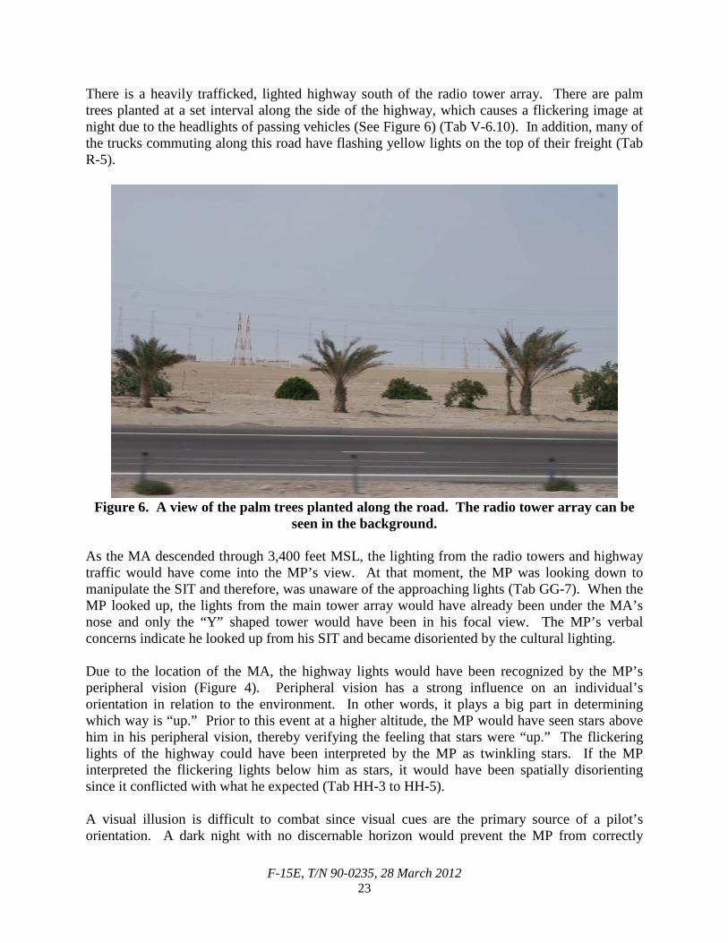
There is a heavily trafficked, lighted highway south of the radio tower array. There are palm trees planted at a set interval along the side of the highway, which causes a flickering image at night due to the headlights of passing vehicles (See Figure 6) (Tab V-6.10). In addition, many of the trucks commuting along this road have flashing yellow lights on the top of their freight (Tab R-5).
Figure 6. A view of the palm trees planted along the road. The radio tower array can be
seen in the background. As the MA descended through 3,400 feet MSL, the lighting from the radio towers and highway traffic would have come into the MP’s view. At that moment, the MP was looking down to manipulate the SIT and therefore, was unaware of the approaching lights (Tab GG-7). When the MP looked up, the lights from the main tower array would have already been under the MA’s nose and only the “Y” shaped tower would have been in his focal view. The MP’s verbal concerns indicate he looked up from his SIT and became disoriented by the cultural lighting. Due to the location of the MA, the highway lights would have been recognized by the MP’s peripheral vision (Figure 4). Peripheral vision has a strong influence on an individual’s orientation in relation to the environment. In other words, it plays a big part in determining which way is “up.” Prior to this event at a higher altitude, the MP would have seen stars above him in his peripheral vision, thereby verifying the feeling that stars were “up.” The flickering lights of the highway could have been interpreted by the MP as twinkling stars. If the MP interpreted the flickering lights below him as stars, it would have been spatially disorienting since it conflicted with what he expected (Tab HH-3 to HH-5). A visual illusion is difficult to combat since visual cues are the primary source of a pilot’s orientation. A dark night with no discernable horizon would prevent the MP from correctly
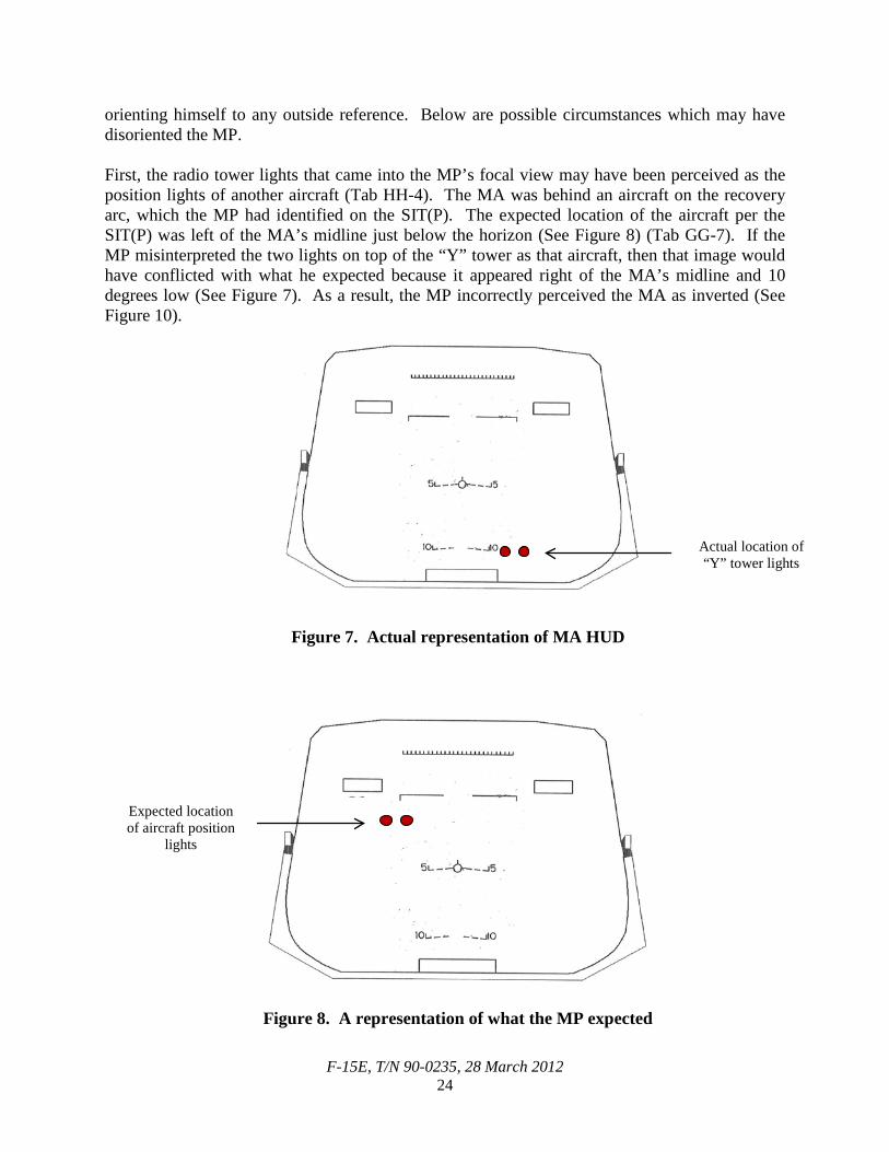
F-15E, T/N 90-0235, 28 March 2012 24
orienting himself to any outside reference. Below are possible circumstances which may have disoriented the MP. First, the radio tower lights that came into the MP’s focal view may have been perceived as the position lights of another aircraft (Tab HH-4). The MA was behind an aircraft on the recovery arc, which the MP had identified on the SIT(P). The expected location of the aircraft per the SIT(P) was left of the MA’s midline just below the horizon (See Figure 8) (Tab GG-7). If the MP misinterpreted the two lights on top of the “Y” tower as that aircraft, then that image would have conflicted with what he expected because it appeared right of the MA’s midline and 10 degrees low (See Figure 7). As a result, the MP incorrectly perceived the MA as inverted (See Figure 10).
Figure 7. Actual representation of MA HUD
Figure 8. A representation of what the MP expected
Actual location of “Y” tower lights
Expected location of aircraft position
lights
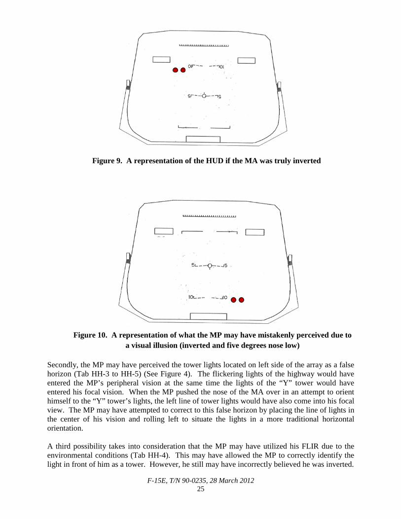
F-15E, T/N 90-0235, 28 March 2012 25
Figure 9. A representation of the HUD if the MA was truly inverted
Figure 10. A representation of what the MP may have mistakenly perceived due to a visual illusion (inverted and five degrees nose low)
Secondly, the MP may have perceived the tower lights located on left side of the array as a false horizon (Tab HH-3 to HH-5) (See Figure 4). The flickering lights of the highway would have entered the MP’s peripheral vision at the same time the lights of the “Y” tower would have entered his focal vision. When the MP pushed the nose of the MA over in an attempt to orient himself to the “Y” tower’s lights, the left line of tower lights would have also come into his focal view. The MP may have attempted to correct to this false horizon by placing the line of lights in the center of his vision and rolling left to situate the lights in a more traditional horizontal orientation. A third possibility takes into consideration that the MP may have utilized his FLIR due to the environmental conditions (Tab HH-4). This may have allowed the MP to correctly identify the light in front of him as a tower. However, he still may have incorrectly believed he was inverted.
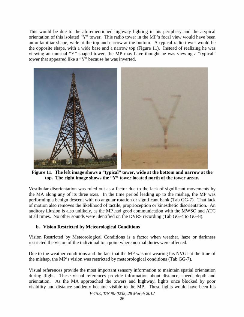
F-15E, T/N 90-0235, 28 March 2012 26
This would be due to the aforementioned highway lighting in his periphery and the atypical orientation of this isolated “Y” tower. This radio tower in the MP’s focal view would have been an unfamiliar shape, wide at the top and narrow at the bottom. A typical radio tower would be the opposite shape, with a wide base and a narrow top (Figure 11). Instead of realizing he was viewing an unusual “Y” shaped tower, the MP may have thought he was viewing a “typical” tower that appeared like a “Y” because he was inverted.
Figure 11. The left image shows a “typical” tower, wide at the bottom and narrow at the
top. The right image shows the “Y” tower located north of the tower array.
Vestibular disorientation was ruled out as a factor due to the lack of significant movements by the MA along any of its three axes. In the time period leading up to the mishap, the MP was performing a benign descent with no angular rotation or significant bank (Tab GG-7). That lack of motion also removes the likelihood of tactile, proprioception or kinesthetic disorientation. An auditory illusion is also unlikely, as the MP had good communication with the MWSO and ATC at all times. No other sounds were identified on the DVRS recording (Tab GG-4 to GG-8).
b. Vision Restricted by Meteorological Conditions
Vision Restricted by Meteorological Conditions is a factor when weather, haze or darkness restricted the vision of the individual to a point where normal duties were affected. Due to the weather conditions and the fact that the MP was not wearing his NVGs at the time of the mishap, the MP’s vision was restricted by meteorological conditions (Tab GG-7). Visual references provide the most important sensory information to maintain spatial orientation during flight. These visual references provide information about distance, speed, depth and orientation. As the MA approached the towers and highway, lights once blocked by poor visibility and distance suddenly became visible to the MP. These lights would have been his
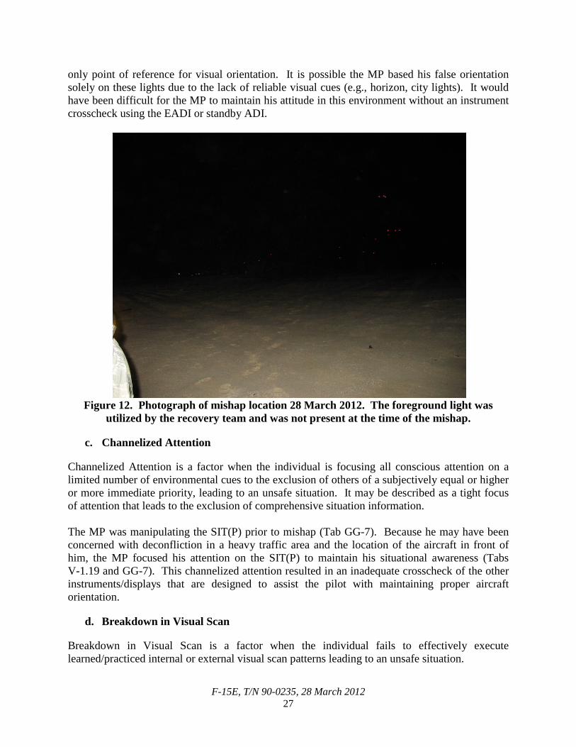
F-15E, T/N 90-0235, 28 March 2012 27
only point of reference for visual orientation. It is possible the MP based his false orientation solely on these lights due to the lack of reliable visual cues (e.g., horizon, city lights). It would have been difficult for the MP to maintain his attitude in this environment without an instrument crosscheck using the EADI or standby ADI.
Figure 12. Photograph of mishap location 28 March 2012. The foreground light was
utilized by the recovery team and was not present at the time of the mishap.
c. Channelized Attention
Channelized Attention is a factor when the individual is focusing all conscious attention on a limited number of environmental cues to the exclusion of others of a subjectively equal or higher or more immediate priority, leading to an unsafe situation. It may be described as a tight focus of attention that leads to the exclusion of comprehensive situation information. The MP was manipulating the SIT(P) prior to mishap (Tab GG-7). Because he may have been concerned with deconfliction in a heavy traffic area and the location of the aircraft in front of him, the MP focused his attention on the SIT(P) to maintain his situational awareness (Tabs V-1.19 and GG-7). This channelized attention resulted in an inadequate crosscheck of the other instruments/displays that are designed to assist the pilot with maintaining proper aircraft orientation.
d. Breakdown in Visual Scan
Breakdown in Visual Scan is a factor when the individual fails to effectively execute learned/practiced internal or external visual scan patterns leading to an unsafe situation.
F-15E, T/N 90-0235, 28 March 2012 28
In accordance with Air Force Manual (AFMAN) 11-217, Vol 1, a proper crosscheck includes a visual scan of the outside environment, as well as using the HUD and an ADI to provide a pilot with the aircraft’s correct attitude. As described above, the SIT provides a bird’s eye view of the surrounding area but lacks information on aircraft attitude. The MP channelized his attention to the SIT(P), causing a breakdown in his visual scan. The evidence suggests the MP looked up from the SIT(P) as he was flying over the highway near the radio tower array (Tab GG-7). The lights would have been unexpected and appear to have immediately disoriented the MP. The MP may have been better equipped to combat this illusion or avoid it completely if he had continuously utilized an effective crosscheck. Maintaining a visual scan outside the cockpit would have allowed the radio towers to slowly develop into the MP’s line of sight instead of the immediate image that may have caused his sudden disorientation. In addition, the evidence suggests that the EADI was not part of the MP’s display panel at the time of the mishap (Tab GG-7 to GG-8). The EADI would have displayed the MA’s true upright orientation. By not having the EADI in his visual scan, the MP lacked a vital instrument that could have helped him avoid/overcome his disorientation.
e. Expectancy
Expectancy is a factor when the individual expects to perceive a certain reality and those expectations are strong enough to create a false perception of the expectation. The MP may have experienced the following three individual factors of Expectancy: The environment of the area was repeatedly briefed to the MP as “very dark” (Tab V-1.14 and V-4.8). The MP did not expect to see cultural lighting until he was approaching the runway at the deployed location. The appearance of red tower lights and flickering highway lights were unexpected and may have been interpreted by the MP as lights above an indiscernible horizon. Based on what he was seeing on the SIT(P), the MP expected the aircraft in front of him to be to his left (Tab GG-7). A tower light misinterpreted as an aircraft would have appeared to be on the MP’s right. This perceived inverted image of the expected scene, along with the peripheral lighting of the highway below, could have caused the MP to become disoriented (See Figures 7 to 10). The MP’s disorientation caused him to believe that he was inverted and five degrees nose low. The MP attempted to level the MA to his perceived horizon by pushing forward on the MA controls (Tab J-10). The MP expected this maneuver to push the nose of the MA toward the horizon. In reality, the MA acted in accordance with the forward stick input and pitched further away from the horizon (Tab J-10). This increased nose low attitude contradicted the MP’s expectation of what the MA should have done. The MP likely was then attempting to identify why the MA did not follow his command, which would have caused further disorientation.
f. Error due to Misperception
Error due to Misperception is a factor when an individual acts or fails to act based on an illusion; misperception or disorientation state and this act or failure to act creates an unsafe situation.
F-15E, T/N 90-0235, 28 March 2012 29
The MP performed recovery maneuvers to correct his perceived orientation. He pitched the MA down 20 degrees nose low and rolled left 70 degrees. The MP maintained this position for approximately one second and then continued to roll left to a fully inverted position (Tab J-3). The recovery maneuvers were incorrect, as the MP inverted the MA at approximately 1,800 feet AGL and 25 degrees nose low, creating an unsafe situation for the MC (Tab GG-8). Stick force analysis revealed all movements were controlled by the MC (Tab J-14).
g. Air Traffic Control Resources
Air Traffic Control Resources is a factor when inadequate monitoring of airspace, enroute navigational aids or language barriers in air traffic controllers causes an unsafe situation. The MP was instructed by ATC to descend to 2,000 feet MSL earlier than expected or briefed (Tab V-1.10). That caused a decrease in the vertical distance between the MA and the radio tower, which resulted in a corresponding increase in the visibility of the radio towers’ lights and the highway lighting. The MA being five degrees nose low also introduced the lights into the MP’s focal vision. As was their common practice, ATC made frequent requests to the aircraft participating in the LFE to descend to 2,000 feet MSL earlier than depicted on the approach plate and was not consistent with what was briefed. By isolating aircraft at 2,000 feet MSL early, ATC was able to spend more time and attention on controlling the remaining aircraft entering the arc (Tab V-7.4 to V-7.5). However, this practice of placing an aircraft at lower altitudes for longer periods of time and earlier than planned or expected, decreased the margin for error. 12. GOVERNING DIRECTIVES AND PUBLICATIONS
(1) AFI 11-202, Vol 3, General Flight Rules, 22 October 2010 (2) AFI 11-214, Air Operations Rules and Procedures, 22 December 2005, Incorporating
Change (IC) 2, 2 June 2009 (3) AFI 11-2F-15E, Vol 1, F-15E -- Aircrew Training, 31 March 2011 (4) AFI 11-2F-15E, Vol 3, F-15E -- Operations Procedures, 11 August 2009 (5) AFI 11-418, Operations Supervision, 15 September 2011 (6) AFI 51-503, Aerospace Accident Investigations, 26 May 2010 (7) AFI 91-204, Safety Investigations and Reports, 24 September 2008, DOD HFACS (8) AFMAN 11-217, Vol 1, Instrument Flight Procedures, 22 October 2010 (9) AFTTP 3-3.F-15E, Combat Aircraft Fundamentals, 4 November 2011 (10)TO 00-20-1, Aerospace Equipment Maintenance Inspection, Documentation,
Policies, and Procedures, 1 September 2010 (11)TO 1F-15E-1-2-1, Flight Manual, 1 July 2009, IC 1, 1 May 2011 (12)TO 1F-15E-1-2-1 CL-1, Flight Crew Checklist, 1 July 2009, IC 3, 15 January 2012 (13)TO 1F-15E-2-31GS-01-1, Indicating/Recording Systems After TO 1F-15E-807
(ADCP), 15 July 2006
F-15E, T/N 90-0235, 28 March 2012 30
(14)TO 1F-15E-2-34SD-00-1, Navigation System, 1 April 2006 (15)TO 1F-15E-34-1-1, Nonnuclear Weapon Delivery Manual, 1 July 2009, IC 1,
1 December 2010
NOTICE: The AFIs listed above are available digitally on the AF Departmental Publishing Office internet site at: http://www.e-publishing.af.mil. 13. ADDITIONAL AREAS OF CONCERN
a. EADI Use
Like most USAF aircraft with glass cockpits, the F-15E does not have a primary mechanical ADI gauge or a dedicated display for the aircraft’s primary attitude instrument (Tab BB-16). Although there is a mechanical standby ADI, the gauge is very small, often unreliable, seldom referenced and may be unlit during nighttime operations to prevent glare in the cockpit (Tab GG-15). As a result, it is incumbent upon the pilot to call up the EADI “when conditions warrant it” or when required by AFI 11-2F-15E, Vol 3. This AFI only directs the pilot to call up the EADI during IMC. This approach raises two concerns relevant to this mishap. First, it does not acknowledge that although night flying is not inherently considered the same as IMC, reduced visual cues and environmental conditions can make night flying very similar to IMC. Second, it discounts the inherent advantage of having an ADI available in order to prevent spatial disorientation, even in what is technically VMC, by allowing the pilot to accomplish a sound crosscheck or an unconscious scan of his primary flight instrument while performing other cockpit duties.
b. VSI / Lip Light / Instrument Lighting
There were was not enough information to determine if the following three pieces of evidence were relevant to the mishap. First, the front cockpit VSI (located on the standby instrument panel) had been written up on several occasions, including the flight prior to the mishap (Tab U-3). Because the VSI was not recovered in the mishap wreckage, we have no way to determine what the front cockpit VSI was reading at the time of the accident and whether it was a factor in the mishap. Second, the front cockpit lighting control panel, which controls lighting levels for all the standby instruments including the standby ADI and the VSI gauge, was not recovered (Tabs J-6 to J-7 and U-5 to U-7). The locations of switches on this panel could have confirmed the lighting level on the standby instrument panel at the time of the mishap and helped determine if MP may have possibly had these instruments in his crosscheck. Third, post-mishap testing of the MP’s lip light revealed the bulb was in working order, but there was no way to determine if the MP’s lip light was functioning properly during the MS (Tab GG-16). Just prior to pushing out of holding on the tactical portion of their mission, the MP stated, “What is wrong with my lip light?” However, the MP never mentioned his lip light again (Tab GG-6 to GG-8). Pilots often use a lip light as a light source when they dim or shut off lights in the cockpit while wearing NVGs (Tab GG-14). Therefore, the lip light data would have been

F-15E, T/N 90-0235, 28 March 2012 32
STATEMENT OF OPINION
F-15E, T/N 90-0235, Southwest Asia 28 MARCH 2012
Under 10 U.S.C. 2254(d), any opinion of the accident investigators as to the cause of, or the factors contributing to, the accident set forth in the accident investigation report, if any, may not be considered as evidence in any civil or criminal proceeding arising from the accident, nor may such information be considered an admission of liability of the United States or by any person referred to in those conclusions or statements. 1. OPINION SUMMARY I find by clear and convincing evidence that the cause of the mishap was the Mishap Pilot (MP) becoming spatially disoriented due to a visual illusion during his nighttime recovery to his deployed operating location. Further, I find by a preponderance of the evidence that the following factors substantially contributed to the mishap: (1) the lack of an effective instrument crosscheck by the MP and (2) a combination of the environmental and procedural factors present on the approach to the base. 2. DISCUSSION OF OPINION On Wednesday, 28 March 2012 at approximately 1603Z, the Mishap Aircraft (MA), an F-15E, Tail Number 90-0235, impacted the ground approximately 18 nautical miles (NM) west, southwest of the operating location of the 380th Air Expeditionary Wing in Southwest Asia. After participating in a large force exercise (LFE) and during the recovery to base, the MP became spatially disoriented and flew the MA into an inverted position. The Mishap Weapon Systems Officer (MWSO) subsequently attempted to recover the MA and ejected both crew members. The MWSO ejected safely, with only minor injuries, and was recovered by U.S. and Host Nation (HN) forces. The MP was fatally injured when his ejection sequence was interrupted by contact with a 377-foot tower that was part of a large radio tower array. The MA was destroyed after contacting the same tower and subsequently the ground. The MA loss is valued at $47,094,662.60. The MA caused damage to HN property. Media interest was national and reported via multiple outlets. Mission preparation, briefing, ground operations, and takeoff were all conducted without any significant difficulties. The tactical portion of the mission was uneventful.
a. Cause: Spatial Disorientation of the MP The mishap sortie was flown in support of an LFE and the Mishap Crew (MC) was acting as the flight lead of a two-ship of F-15Es in a strike package of approximately 27 aircraft. At the conclusion of the tactical portion of the mission, the MC removed their night vision goggles
F-15E, T/N 90-0235, 28 March 2012 33
(NVGs) and began the recovery to base and directed their wingman to maintain a two NM radar trail formation. Below 10,000 feet mean sea level (MSL), blowing dust and sand made the ability to discern the horizon, with or without NVGs, impossible. At approximately 3,100 feet MSL, five degrees nose low and in a wings-level attitude, the MP incorrectly interpreted the visual scene in front of him and began a series of abrupt maneuvers that ultimately resulted in him rolling the MA into an inverted attitude at 1,800 feet AGL and 25 degrees nose low. Because the MC’s recovery primarily consisted of a long, gradual descent, with very few turns or significant changes in acceleration, it is highly unlikely that any type of inner ear or vestibular disorientation occurred. Aircrew members highlighted the fact that it had been well communicated (via local area orientation, LFE and flight briefings) that the recovery to base would be very dark. In fact, this had been so well communicated that detecting any lights on the ground was most likely unexpected and therefore, potentially disorienting. Due to the lack of any significant topographical features, the expected lack of cultural lighting, the reduced visibility and the lack of a discernable horizon, the MP most likely became disoriented by the cultural lighting in the vicinity of the mishap site and incorrectly perceived that the MA was inverted and five degrees nose low. Furthermore, the actions taken by the MP after the disorientation occurred indicate that he was attempting to bunt or push the nose of the MA back to what he perceived was the horizon. Although the MA responded appropriately and flew to a further nose low position, this was not the response the MP expected from the MA and this would have added to his confusion and disorientation. In a further attempt to recover the MA, the MP performed a left roll of approximately 70 degrees, paused momentarily, and then continued the left roll until the MA was in a fully inverted attitude. It was during this final roll that the MWSO became convinced the MP had become disoriented and took control of the MA. After attempting to recover the MA, the MWSO initiated ejection for the MC.
b. Substantially Contributing Factors
(1) Lack of an Effective Instrument Crosscheck by the MP
A preponderance of the evidence suggests that the MP was not performing an effective instrument crosscheck at the time of the mishap. Specifically, all evidence suggests that the MP did not have the electronic attitude director indicator (EADI), the primary source of aircraft attitude, up on any of his cockpit displays and was channelized on his situation display (SIT). Although having the EADI present in night/visual meteorological conditions is not required by Air Force Instruction 11-2F-15E, Volume 3, a conscious and subconscious crosscheck of this primary instrument can avoid and/or aid in a recovery from any spatial disorientation situation. The standard place for an F-15E pilot to display an EADI is the multi-purpose color display (MPCD). However, during the seconds prior to the MP becoming disoriented, he was manipulating the SIT on his MPCD and continued to have the SIT displayed until he rolled the MA into an inverted attitude. Therefore, I believe that the MP was using his HUD and the visual environment as the source of his attitude. Subsequently, visual stimuli from light sources on the ground caused the MP to misinterpret his attitude and because this illusion was so strong, he initially did not make any attempt to call up the EADI on the MPCD or confirm his attitude with his standby instruments. Instead, he continued to maneuver the MA in accordance with his mistaken visual interpretation of his attitude and flew the MA into an inverted position. By not
F-15E, T/N 90-0235, 28 March 2012 35
INDEX OF TABS F-15E, T/N 90-0235, Southwest Asia
28 MARCH 2012
DISTRIBUTION LETTER AND SAFETY INVESTIGATOR INFORMATION……………………………… A THIS TAB NOT USED……………………………………………………………………………………………… B THIS TAB NOT USED……………………………………………………………………………………………… C MAINTENANCE REPORT, RECORDS, AND DATA…………………………………………………………… D THIS TAB NOT USED……………………………………………………………………………………………… E WEATHER AND ENVIRONMENTAL RECORDS AND DATA……………………………………………..... F PERSONNEL RECORDS……………………………………………………….………………………………….. G EGRESS, IMPACT, AND CRASHWORTHINESS ANALYSIS………………………………………………… H DEFICIENCY REPORTS…………………………………………………………………….…………………….. I RELEASABLE TECHNICAL REPORTS AND ENGINEERING EVALUATIONS………………………….. J MISSION RECORDS AND DATA………………………………………………………………………………… K DATA FROM ON-BOARD RECORDERS……………………………………………………………………….. L DATA FROM GROUND RADAR AND OTHER SOURCES…………………………………………………… M TRANSCRIPTS OF VOICE COMMUNICATIONS……………………………………………………………… N ANY ADDITIONAL SUBSTANTIATING DATA AND REPORTS…………………………………………….. O DAMAGE AND INJURY SUMMARIES……………………………………………………………………….…. P AIB TRANSFER DOCUMENTS……………………………………………………………………………..……. Q RELEASABLE WITNESS TESTIMONY…………………………………………………………………………. R RELEASABLE PHOTOGRAPHS, VIDEOS, AND DIAGRAMS……………………………………………….. S INDIVIDUAL FLIGHT RECORDS AND ORDERS (not included in Tab G) …………………………………. T AIRCRAFT MAINTENANCE RECORDS (not included in Tab D) ……...……………………..……………… U WITNESS TESTIMONY AND STATEMENTS…………………………………………………….……………. V WEATHER OBSERVATIONS (not included in Tab F)..………………………………………………………… W STATEMENTS OF INJURY OR DEATH…………………………………………………………………….….. X DOCUMENTS APPOINTING THE AIB MEMBERS…………………………………………………………… Y
F-15E, T/N 90-0235, 28 March 2012 36
PHOTOGRAPHS (not included in Tab S)…………..……………………………………………………………… Z FLIGHT DOCUMENTS……………………………………………………………………….……………………. AA GOVERNMENT DOCUMENTS AND REGULATIONS………………………………………………………… BB FACT SHEETS…………………………….…………………………………………………………..…………….. CC MEDIA…………………………….…………………………………………………………..…………….………... DD MISHAP SITE DATA COLLECTED BY AIB……………………………………………………..…………...…. EE FIRE PROTECTION BRANCH COMPREHENSIVE EVENT REPORT…………………………….….…….. FF MEMORANDA FROM AIB PILOT MEMBER…………………………….…………………………………..... GG HUMAN FACTORS ANALYSIS …………………………………………….……………………..……………….HH DAILY RECORDS OF FACILITY OPERATION……….……………………………………………..…………….II APPROVAL FOR RELEASE OF BOEING TECHNICAL REPORTS………….…………………………………JJ