Embed Size (px)
Citation preview
Paul A. Lagace © 2008
MIT - 16.003/16.004 Spring, 2009
16.003/004 -- “Unified Engineering”Department of Aeronautics and Astronautics
Massachusetts Institute of Technology
Unit M4.4Simple Beam Theory
Readings:CDL 7.1 - 7.5, 8.1, 8.2
Unit M4-4 - p. 2Paul A. Lagace © 2008
MIT - 16.003/16.004 Spring, 2009
LEARNING OBJECTIVES FOR UNIT M4.4
Through participation in the lectures, recitations, and workassociated with Unit M4.4, it is intended that you will beable to………
• ….describe the aspects composing the model of abeam associated with deformations/displacementsand stresses (i.e. Simple Beam Theory) andidentify the associated limitations
• ….apply the basic equations of elasticity to derive thesolution for the general case
• ….identify the beam parameters that characterizebeam behavior and describe their role
Unit M4-4 - p. 3Paul A. Lagace © 2008
MIT - 16.003/16.004 Spring, 2009
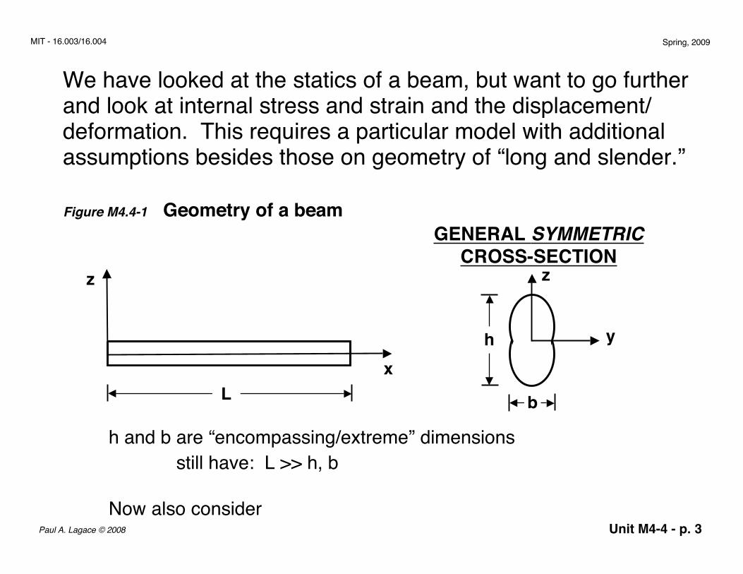
We have looked at the statics of a beam, but want to go furtherand look at internal stress and strain and the displacement/deformation. This requires a particular model with additionalassumptions besides those on geometry of “long and slender.”
Figure M4.4-1 Geometry of a beam
h and b are “encompassing/extreme” dimensionsstill have: L >> h, b
Now also consider
z
xL
GENERAL SYMMETRICCROSS-SECTION
y
z
h
b
Unit M4-4 - p. 4Paul A. Lagace © 2008
MIT - 16.003/16.004 Spring, 2009
Assumptions on Stresses
We have said that loading is in the plane x-z and is transverse to thelong axis (the x-axis)The first resulting assumption from this is:
All loads in y - direction are zero ⇒ all stresses in y-direction are zero:
σyy = σ xy = σ yz = 0--> Next, we “assume” that the only significant stresses are in the x- direction.
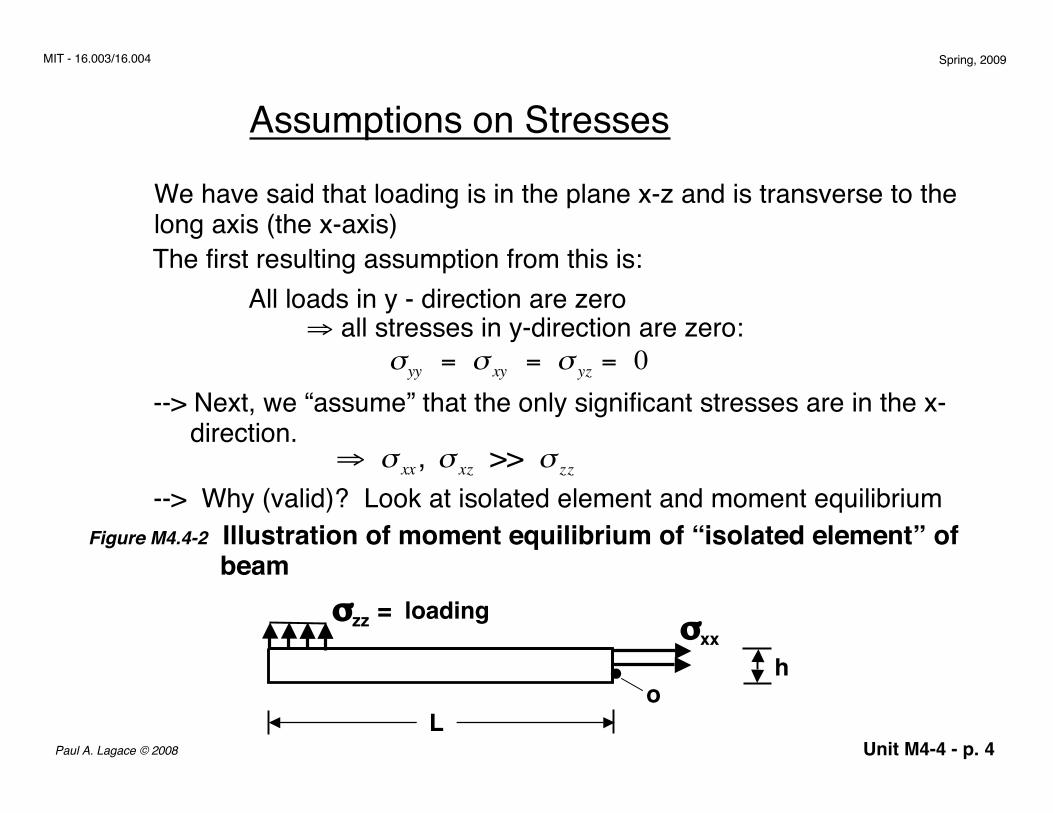
--> Why (valid)? Look at isolated element and moment equilibrium⇒ σ xx, σ xz >> σ zz
Figure M4.4-2 Illustration of moment equilibrium of “isolated element” of beam
L
h• o
σxxσzz = loading
Unit M4-4 - p. 5Paul A. Lagace © 2008
MIT - 16.003/16.004 Spring, 2009
can make same argument for σxz
M0 (magnitude) ⇒ σ zz (moment arm)∑ + σ xx (moment arm) = 0moment arm for σ zz ≈ Lmoment arm for σ xx ≈ hbut, h << L ⇒ σ xx >>σ zz
--> thus, assumption is only non zero stresses are σxz and σxx
⇒ σ zz ≈ 0
To complete our model, we need….
moment arm for σ zz ≈ Lmoment arm for σ xx ≈ h;
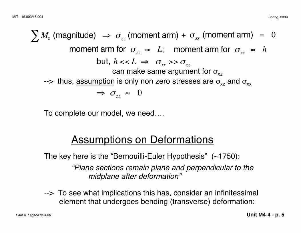
Assumptions on DeformationsThe key here is the “Bernouilli-Euler Hypothesis” (~1750):
“Plane sections remain plane and perpendicular to the midplane after deformation”
--> To see what implications this has, consider an infinitessimal element that undergoes bending (transverse) deformation:
Unit M4-4 - p. 6Paul A. Lagace © 2008
MIT - 16.003/16.004 Spring, 2009
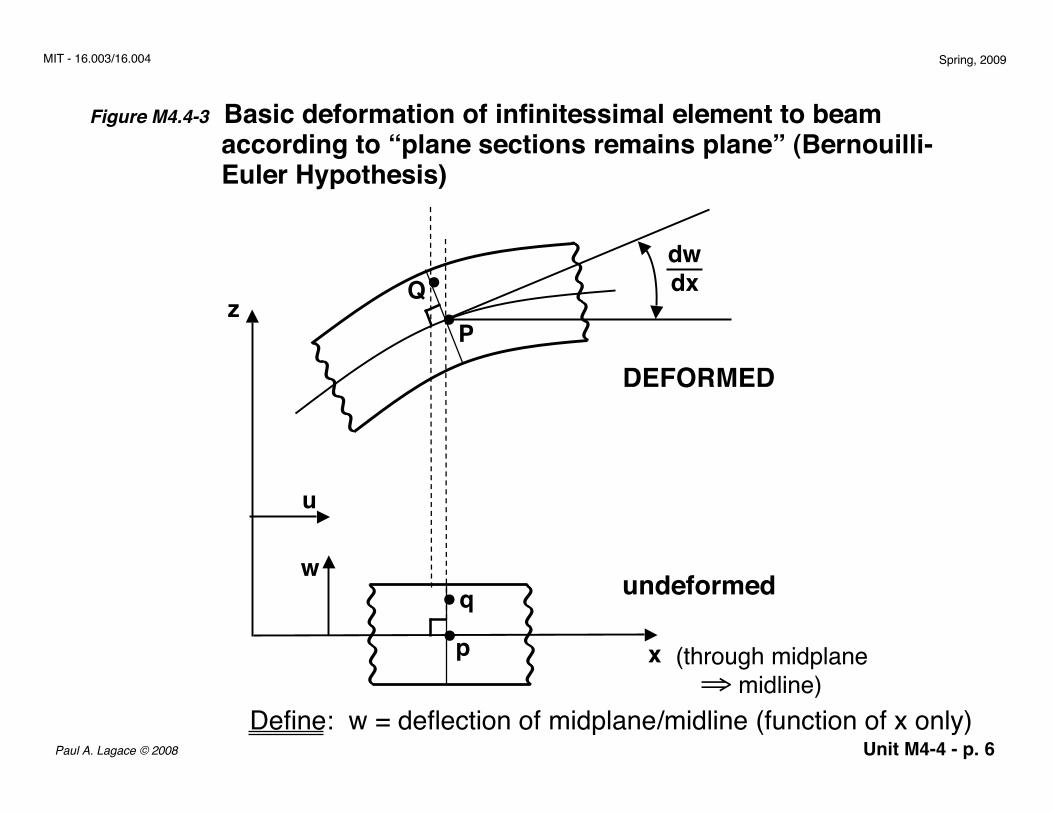
Figure M4.4-3 Basic deformation of infinitessimal element to beam according to “plane sections remains plane” (Bernouilli- Euler Hypothesis)
(through midplane⇒ midline)
z
x
undeformed
DEFORMED
w
~~~~~~~~
~~~~~~~~
•• q
p
~ ~ ~ ~ ~ ~ ~ ~
~~~~~~ ~~••Q
P
u
dw dx
Define: w = deflection of midplane/midline (function of x only)
Unit M4-4 - p. 7Paul A. Lagace © 2008
MIT - 16.003/16.004 Spring, 2009
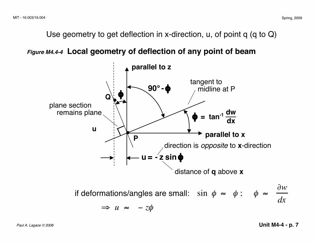
Use geometry to get deflection in x-direction, u, of point q (q to Q)
Figure M4.4-4 Local geometry of deflection of any point of beam
parallel to x•
•Q
Pu
dw dxφ = tan-1
parallel to z
tangent tomidline at P
plane sectionremains plane
φ90° - φ
u = - z sin φ
distance of q above x
direction is opposite to x-direction
if deformations/angles are small:⇒ u ≈ − zφ
sin φ ≈ φ ; φ ≈ ∂wdx
Unit M4-4 - p. 8Paul A. Lagace © 2008
MIT - 16.003/16.004 Spring, 2009
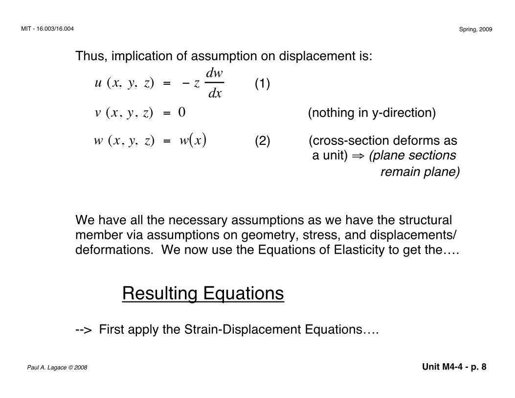
Thus, implication of assumption on displacement is:
u (x, y, z) = − z dwdx
v (x, y, z) = 0w (x, y, z) = w x( )w (x, y, z) = w x( )
(1)
(2)
(nothing in y-direction)
(cross-section deforms as a unit) ⇒ (plane sections remain plane)
We have all the necessary assumptions as we have the structuralmember via assumptions on geometry, stress, and displacements/deformations. We now use the Equations of Elasticity to get the….
Resulting Equations
--> First apply the Strain-Displacement Equations….
Unit M4-4 - p. 9Paul A. Lagace © 2008
MIT - 16.003/16.004 Spring, 2009
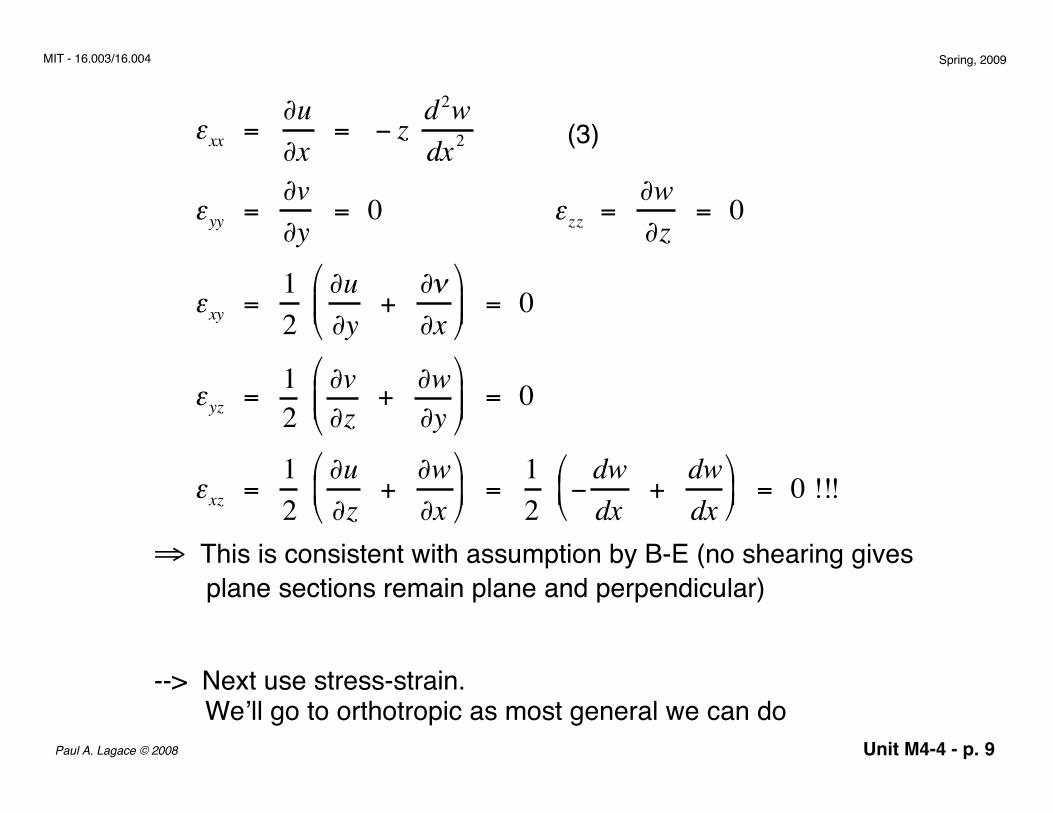
⇒ This is consistent with assumption by B-E (no shearing gives plane sections remain plane and perpendicular)
--> Next use stress-strain. We’ll go to orthotropic as most general we can do
(3)εxx = ∂u∂x
= − z d2wdx2
εyy = ∂v∂y
= 0 εzz = ∂w∂z
= 0
εxy = 12
∂u∂y
+ ∂ν∂x
= 0
εyz = 12
∂v∂z
+ ∂w∂y
= 0
εxz = 12
∂u∂z
+ ∂w∂x
= 1
2 −
dwdx
+ dwdx
= 0 !!!
Unit M4-4 - p. 10Paul A. Lagace © 2008
MIT - 16.003/16.004 Spring, 2009
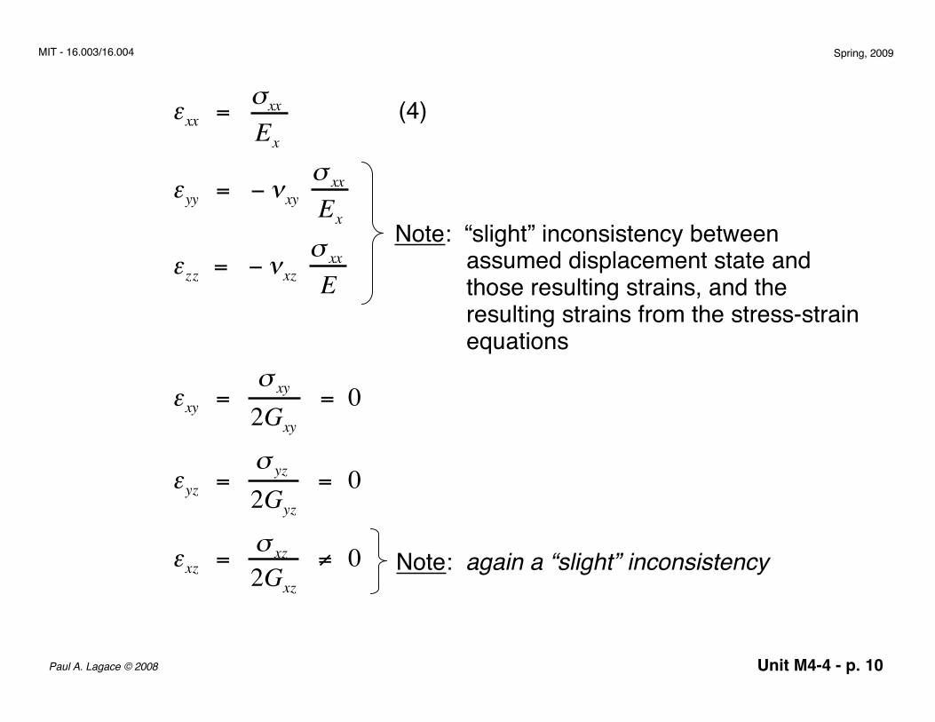
(4)
Note: “slight” inconsistency between assumed displacement state and those resulting strains, and the resulting strains from the stress-strain equations
Note: again a “slight” inconsistency
εxy = σ xy
2Gxy
= 0
εyz = σ yz
2Gyz
= 0
εxz = σ xz
2Gxz
≠ 0
εxx = σxx
Ex
εyy = − νxy σ xx
Ex
εzz = − νxz σ xx
E
Unit M4-4 - p. 11Paul A. Lagace © 2008
MIT - 16.003/16.004 Spring, 2009
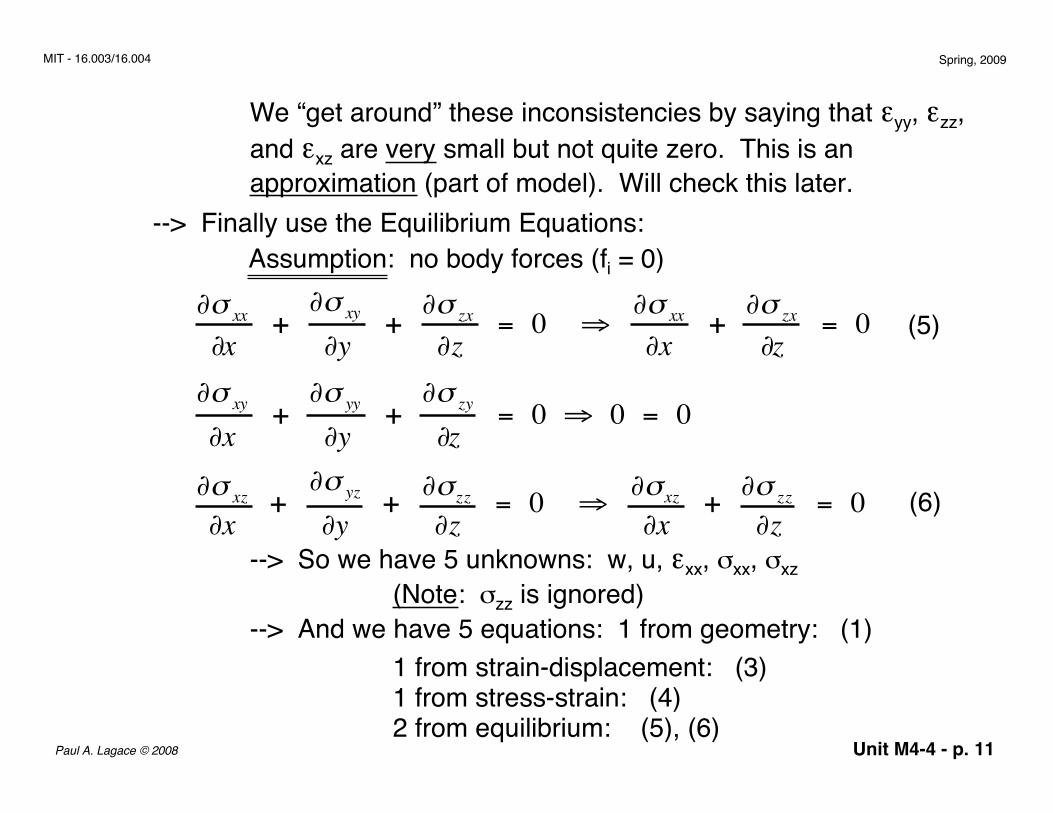
We “get around” these inconsistencies by saying that εyy, εzz,and εxz are very small but not quite zero. This is anapproximation (part of model). Will check this later.
--> Finally use the Equilibrium Equations:Assumption: no body forces (fi = 0)
--> So we have 5 unknowns: w, u, εxx, σxx, σxz(Note: σzz is ignored)
--> And we have 5 equations: 1 from geometry: (1)1 from strain-displacement: (3)1 from stress-strain: (4)2 from equilibrium: (5), (6)
(5)
(6)
∂σ xx
∂x +
∂σ xy
∂y + ∂σ zx
∂z = 0 ⇒ ∂σ xx
∂x + ∂σ zx
∂z = 0
∂σ xy
∂x +
∂σ yy
∂y +
∂σ zy
∂z = 0 ⇒ 0 = 0
∂σ xz
∂x +
∂σ yz
∂y + ∂σ zz
∂z = 0 ⇒ ∂σxz
∂x + ∂σ zz
∂z = 0
Unit M4-4 - p. 12Paul A. Lagace © 2008
MIT - 16.003/16.004 Spring, 2009
z y
xσxx
σxz
h F
S
M
b• • • •
• • • •
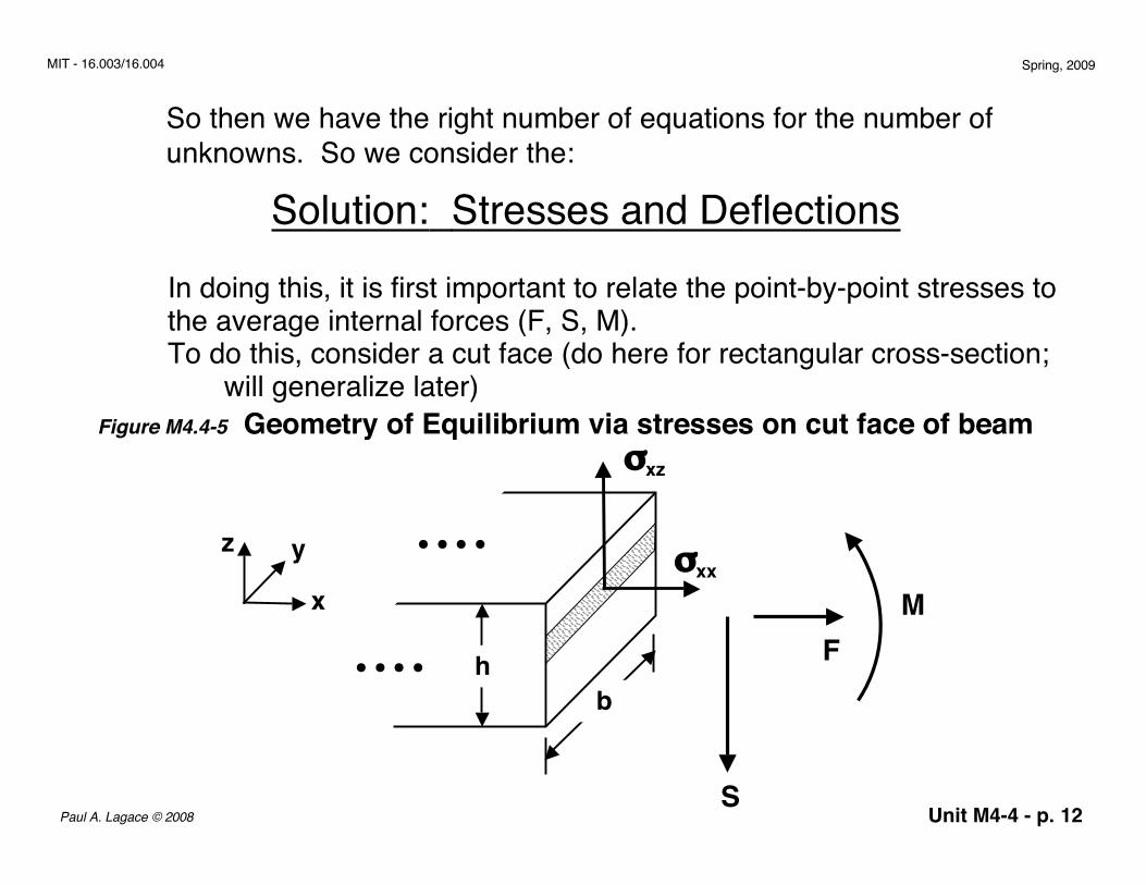
So then we have the right number of equations for the number ofunknowns. So we consider the:
Solution: Stresses and DeflectionsIn doing this, it is first important to relate the point-by-point stresses tothe average internal forces (F, S, M).To do this, consider a cut face (do here for rectangular cross-section; will generalize later)
Figure M4.4-5 Geometry of Equilibrium via stresses on cut face of beam
Unit M4-4 - p. 13Paul A. Lagace © 2008
MIT - 16.003/16.004 Spring, 2009
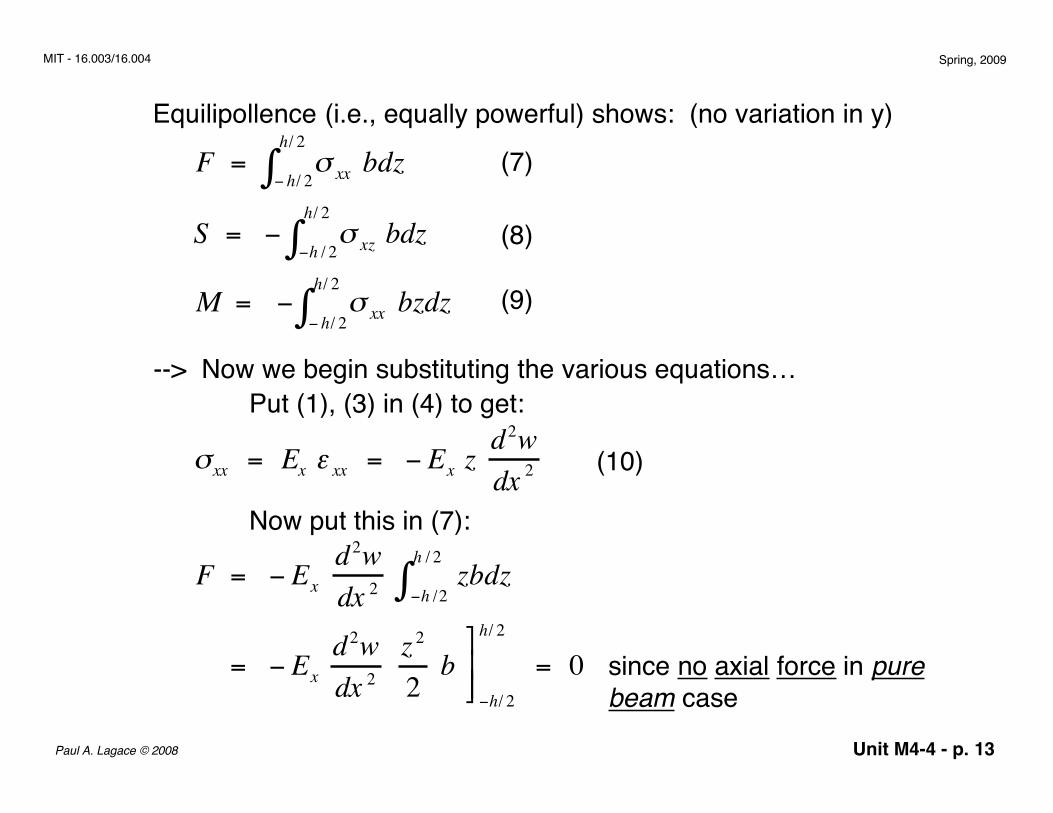
Equilipollence (i.e., equally powerful) shows: (no variation in y)
(7)
(8)
(9)
--> Now we begin substituting the various equations…Put (1), (3) in (4) to get:
(10)
Now put this in (7):
since no axial force in purebeam case
F = σ xx bdz− h/ 2
h/ 2
∫S = − σ xz bdz−h / 2
h/ 2
∫M = − σ xx bzdz
− h/ 2
h/ 2
∫
σxx = Ex ε xx = − Ex z d2wdx 2
F = − Ex d2wdx 2
zbdz−h /2
h / 2
∫
= − Ex d2wdx 2
z2
2 b
−h/ 2
h/ 2
= 0
Unit M4-4 - p. 14Paul A. Lagace © 2008
MIT - 16.003/16.004 Spring, 2009
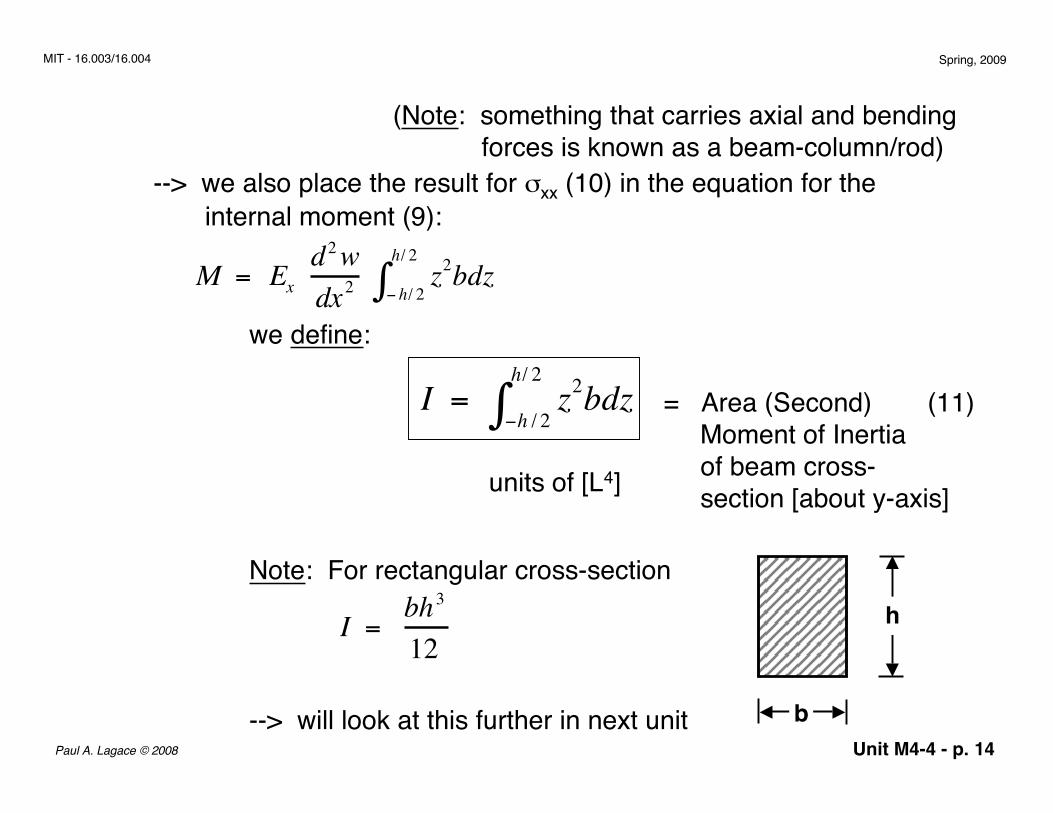
(Note: something that carries axial and bending forces is known as a beam-column/rod)
--> we also place the result for σxx (10) in the equation for the internal moment (9):
M = Ex d2wdx2
z2bdz− h/ 2
h/ 2
∫we define:
= Area (Second) Moment of Inertia of beam cross- section [about y-axis]
(11)
units of [L4]
Note: For rectangular cross-sectionh
b
I = bh3
12
--> will look at this further in next unit
I = z2bdz−h / 2
h/ 2
∫
Unit M4-4 - p. 15Paul A. Lagace © 2008
MIT - 16.003/16.004 Spring, 2009
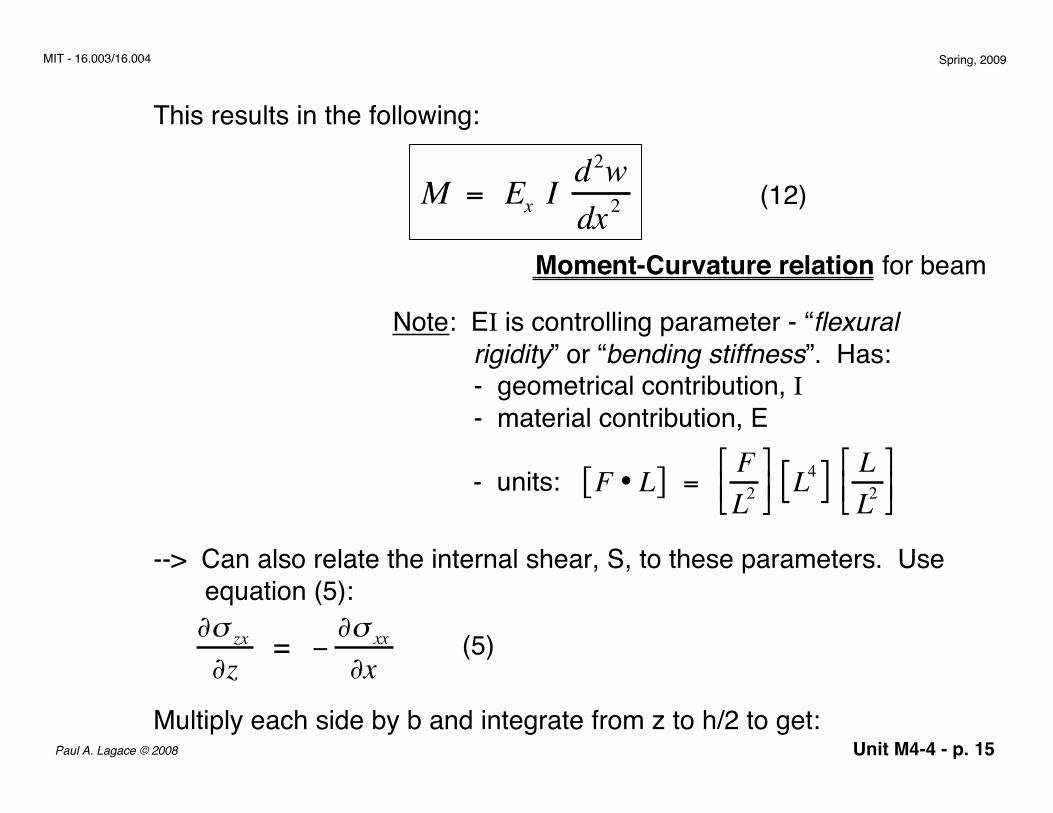
This results in the following:
M = Ex I d2wdx2
(12)
Moment-Curvature relation for beam
Note: EI is controlling parameter - “flexural rigidity” or “bending stiffness”. Has: - geometrical contribution, I - material contribution, E
- units:
--> Can also relate the internal shear, S, to these parameters. Use equation (5):
∂σ zx
∂z = − ∂σ xx
∂x(5)
Multiply each side by b and integrate from z to h/2 to get:
F • L[ ] = FL2
L4[ ] L
L2
Unit M4-4 - p. 16Paul A. Lagace © 2008
MIT - 16.003/16.004 Spring, 2009
b ∂σ zx
∂z dz
z
h/ 2
∫ = − ∂σ xx
∂x bdz
z
h/ 2
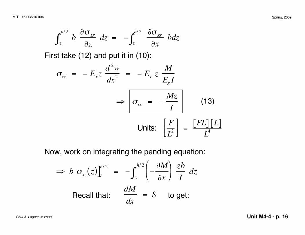
∫First take (12) and put it in (10):
⇒ σxx = − MzI
(13)
Units: FL2
= FL[ ] L[ ]
L4
Now, work on integrating the pending equation:
⇒ b σxz z( )]zh/ 2 = − −
∂M∂x
z
h/ 2
∫ zbI
dz
Recall that: to get:dMdx
= S
σxx = − Exz d 2wdx2
= − Ex z MEx I
Unit M4-4 - p. 17Paul A. Lagace © 2008
MIT - 16.003/16.004 Spring, 2009
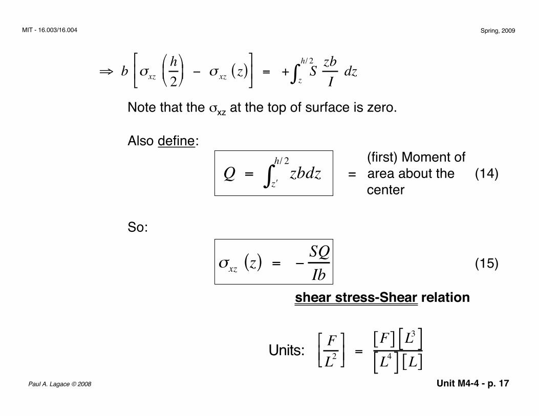
Note that the σxz at the top of surface is zero.
Also define:
σxz z( ) = − SQIb
Units: FL2
=
F[ ] L3[ ]L4[ ] L[ ]
So:
(first) Moment of= area about the center
(14)
(15)
shear stress-Shear relation
⇒ b σxz h2 − σ xz z( )
= + S
z
h/ 2
∫ zbI
dz
Q = zbdz′ z
h/ 2
∫
= z2
2b
′ z
h/ 2
= b2
h2
4 − ′ z 2
Unit M4-4 - p. 18Paul A. Lagace © 2008
MIT - 16.003/16.004 Spring, 2009
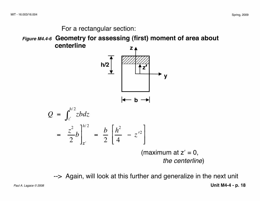
For a rectangular section:Figure M4.4-6 Geometry for assessing (first) moment of area about centerline
b
z
yz′h/2
(maximum at z′ = 0, the centerline)
--> Again, will look at this further and generalize in the next unit
Q = zbdz′ z
h/ 2
∫
= z2
2b
′ z
h/ 2
= b2
h2
4 − ′ z 2
Unit M4-4 - p. 19Paul A. Lagace © 2008
MIT - 16.003/16.004 Spring, 2009
The summary of how we can solve for the stress/strain/displacementstates in a beam is presented in handout M-5
In the next section, we look at what this solution generallymeans and examine it for various situations.
Unit M4-4 - p. 20Paul A. Lagace © 2008
MIT - 16.003/16.004 Spring, 2009
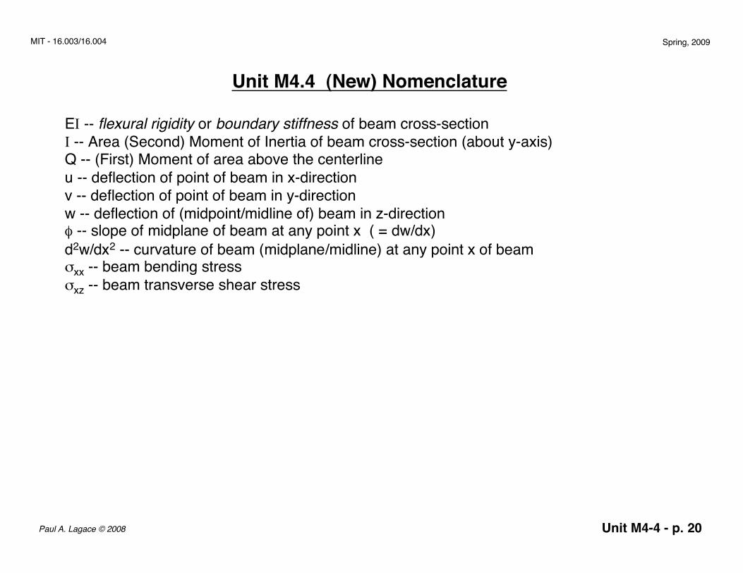
Unit M4.4 (New) Nomenclature
EI -- flexural rigidity or boundary stiffness of beam cross-sectionI -- Area (Second) Moment of Inertia of beam cross-section (about y-axis)Q -- (First) Moment of area above the centerlineu -- deflection of point of beam in x-directionv -- deflection of point of beam in y-directionw -- deflection of (midpoint/midline of) beam in z-directionφ -- slope of midplane of beam at any point x ( = dw/dx)d2w/dx2 -- curvature of beam (midplane/midline) at any point x of beamσxx -- beam bending stressσxz -- beam transverse shear stress