Embed Size (px)
Citation preview

Paul A. Lagace © 2007
MIT - 16.001/16.002 Fall, 2008
16.001/002 -- “Unified Engineering”Department of Aeronautics and Astronautics
Massachusetts Institute of Technology
Unit M3.3Physical Bases of Elastic Properties
Readings:A & J 4, 5, 6

Unit M3.3 - p. 2Paul A. Lagace © 2007
MIT - 16.001/16.002 Fall, 2008
LEARNING OBJECTIVES FOR UNIT M3.3
Through participation in the lectures, recitations, and workassociated with Unit M3.3, it is intended that you will beable to………
• ….identify the various types of atomic bonds and thefactors involved in such
• ….describe the atomic/molecular structure of materialsand the effects on basic material behavior
• ….employ an atomic model to estimate the elasticmodulus of materials
• ….explain the make-up of a composite and thecontributors to its elastic response
Unit M3.3 - p. 3Paul A. Lagace © 2007
MIT - 16.001/16.002 Fall, 2008
We have seen that we can characterize materials on amacroscopic basis using homogenized elastic properties. Butthese elastic properties do depend on the microscopic realityof the material and thus we look at the “structure of thematerial”.
Also will give us some idea as to how we might affect/controlproperties
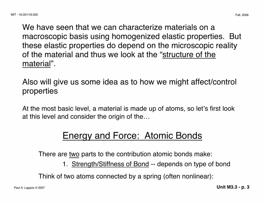
At the most basic level, a material is made up of atoms, so let’s first lookat this level and consider the origin of the…
Energy and Force: Atomic Bonds
There are two parts to the contribution atomic bonds make:1. Strength/Stiffness of Bond -- depends on type of bond
Think of two atoms connected by a spring (often nonlinear):

Unit M3.3 - p. 4Paul A. Lagace © 2007
MIT - 16.001/16.002 Fall, 2008
Figure M3.3-1 Representation of interatomic bond as atoms connected by spring
Stiffness of spring depends on type of bond
2. Arrangement of atoms and bondsThis is the “structure” of the material
Figure M3.3-2 Atomic packing represented as array of springs
versus
Top configuration will be stiffer than bottom configuration for sameindividual bond stiffnesses.

Unit M3.3 - p. 5Paul A. Lagace © 2007
MIT - 16.001/16.002 Fall, 2008
--> Let’s first deal with the types of bonds. We can identify two generictypes:
Primary Bonds
Secondary Bonds
• Ionic, covalent or metallic• Have high melting temperatures (1000°K)• e.g., metals, ceramics
• Hydrogen bonds, Van der Waals• Have lower melting temperatures (100° - 500°K)• e.g., polymers
There are often a mixture of bond types in one material
--> How does one obtain the bond energy of different types for different materials?
Quoted in chemistry databooks. Gives answer as to whether itis favorable to form bonds for particular situations.
--> Let’s first consider each of the three types of…

Unit M3.3 - p. 6Paul A. Lagace © 2007
MIT - 16.001/16.002 Fall, 2008
Ionic Bonding(e.g., alkali halides, magnesia, alumina)
• Electrostatic attraction between ions• Electron goes from positive ion to negative ion
Figure M3.3-3 Example of Ionic Bond to form sodium chloride
+11 +17
–
–
––
––
– –
––
––
–
––
––
––
––
–
––
––
– –
–Na+ + 5.14 eV Cl –– 4.02 eV
rEnergy associated with bond:
1. Work of Ionization (removal/gain of electrons) = UiIt takes 5.14eV - 4.02eV = 1.12eV to make Na+/Cl- separate ions
Primary Bonds

Unit M3.3 - p. 7Paul A. Lagace © 2007
MIT - 16.001/16.002 Fall, 2008
2. Work to separate ionsNa+/Cl- attract in an omnidirectional fashion with:
Force between charged particlesAnd the energy is the integral of the force needed to take these twoions from ∞ (fully separated) to a distance r (the equilibriumdistance):
3. Repulsive EnergyThere is a repulsive force due to the electronic charge distributions inthe atoms. This has the form:
Urep = Brn
Finally we add these parts to get the total energy:
Force = Fatt = q2
4πεor2 ( εo = permittivity)
Energy = Uatt = Fdrr
∞
∫ = − q 2
4πεorr

Unit M3.3 - p. 8Paul A. Lagace © 2007
MIT - 16.001/16.002 Fall, 2008
Figure M3.3-4 Representation of energies associated with ionic bonding for NaCl
U
rUattractive
Urepulsive
Ui
stable region(U < 0)
net curve
ro
minimum point at ro
⇒ no energy neededto keep it there
U = Ui + Uatt + Urep
U = − q 2
4πεor + B
rn⇒

Unit M3.3 - p. 9Paul A. Lagace © 2007
MIT - 16.001/16.002 Fall, 2008
Note: Ionic bonds are omni-directional --charged particles attract equally in all directions
⇒ leads to isotropic behavior, but different sized ions lead to non- isotropic behavior
--> Covalent Bonding(e.g., diamond, silicon, glasses, some metals, also polymer chains)
• Electron shared by two (or more) atoms• Very strong
Figure M3.3-5 Example of covalent bond to form hydrogen moleculeH
+H
r
1 electronin orbit
1 electronin orbit
2 electronsin orbit
H2
Shared electron goes to a new molecular orbit thereby reducing theenergy.
The next bond type is the….

Unit M3.3 - p. 10Paul A. Lagace © 2007
MIT - 16.001/16.002 Fall, 2008
The energy is again made of two parts (attractive and repulsive) andcan be expressed empirically as:
U = − Arm
+ Brn
attractive repulsive(with m < n)(m > 2)
Figure M3.3-6 Representation of energies associated with covalent bondU
rUattractive
Urepulsive
stable region(U < 0)
net curve
ro
minimum point at ro
⇒ no energy neededto keep it there

Unit M3.3 - p. 11Paul A. Lagace © 2007
MIT - 16.001/16.002 Fall, 2008
For most other atoms (e.g., diamond), the shared orbital paths havepreferred directions and thus covalent bonds are generally highlydirectional.
Note: Generally ceramics are bonded by a mixture of ionic and covalent bonds.
the final primary bond type is the…..
--> Metallic Bond(dominant in metals and alloys)
• A “sea” of free electrons which have “left” highest energy atoms (making them ions)
Figure M3.3-7 Representation of free electrons in metallic bonding
+ + +
++++
++++
– ––
––
–––
––
––
––
–– –
– –––
–––
–
–
+ = ions= free electrons

Unit M3.3 - p. 12Paul A. Lagace © 2007
MIT - 16.001/16.002 Fall, 2008
There is attraction and repulsion in this mix of positive and negativecharges. This can be best represented by an expression of thesame form as for a covalent bond:
U = − Arm
+ Brn
attractive repulsive(m < n)
Notes:• Easy movement of electrons leads to high electrical conductivity of metals• No directionality of this configuration (with regard to bonds) ⇒ “omni-directional”
Now let’s quickly consider….
Secondary Bonds
First consider….

Unit M3.3 - p. 13Paul A. Lagace © 2007
MIT - 16.001/16.002 Fall, 2008
Figure M3.3-8 Representation of Van der Waals bonding
r
– + – +
random dipoleon first atom
induced dipoleon second atom
next….--> Hydrogen Bonding• Hydrogen atom gives up charge to nearest oxygen atom• Occurs in water and other polar liquids
--> Van der Waals Bonding• Dipolar attraction between uncharged atoms• Instantaneous position of outer electrons induces change in neighboring atoms (distribution of charge due to motion of atom)

Unit M3.3 - p. 14Paul A. Lagace © 2007
MIT - 16.001/16.002 Fall, 2008
Figure M3.3-9 Representation of hydrogen bonding
H O+ H+
and the neighboring H+ acts as a bridgingbond between neighboring O
– ‘s
H+
H+
H+
H+H
+
–O
–O
–O
This forms repetitive and cross pattern (H2O)Note: for both secondary bonds, the energy is again empirically distributed as the sum of two parts:
U = − Arm
+ Brn
attractive repulsive(m < n)
with the value of m for secondary bonds being larger thanthe value for primary bonds.

Unit M3.3 - p. 15Paul A. Lagace © 2007
MIT - 16.001/16.002 Fall, 2008
--> One can get force by noting that force is the derivative of energy:
Figure M3.3-10 Relationship of (bonding) energy and force
U
rro = equilibriumdistance
inflection point
F ( = dU/dr)
r
Fmax
attraction
repulsion
dU/dr → 0 as r → ∞
F = dUdr

Unit M3.3 - p. 16Paul A. Lagace © 2007
MIT - 16.001/16.002 Fall, 2008
--> Note that the stiffness of an individual bond is the derivative of the force of the bond
Stiffnessof bond
This is linear in a region near the equilibriumdistance r
will return to this point (i.e., linear elastic modulus)
--> Let’s now consider material types and how atoms are arranged (structure) and the types of bonds as well….
Metals and Ceramics: Atomic Packing• Many engineering materials composed of small crystals-grains• Atoms become arranged in certain sequences known as “packing”.• When the material is crystalline, the atomic structure is the one that minimizes the energy of the crystal
= Sbond = dFdr
= d2Udr2

Unit M3.3 - p. 17Paul A. Lagace © 2007
MIT - 16.001/16.002 Fall, 2008
--> Simplification: think of atoms as hard spheres (e.g., pool balls)- packing in plane- stacking of plane to give 3-D crystal
In the plane, often have a “close-packed plane” as a model wherespheres take up least space (minimizes energy)
Figure M3.3-11 Representation of close-packed plane
Out of plane, these close-packed planes stack up.
closed-packed directions (atoms touching)
⇒ Each atom has 6 nearest neighbors in-plane

Unit M3.3 - p. 18Paul A. Lagace © 2007
MIT - 16.001/16.002 Fall, 2008
Figure M3.3-12 Representation of 3-D stacking of two adjacent close- packed planes
= 1st layer atoms
= 2nd layer atoms
There are then two possibilities for the 3rd layer:
--> Possibility 1: Repeat 1st layer1 - 2 -1 - 2 - 1 arrangement
Yields close-packed hexagonal: 1 - 2 - 1 - 2 - 1
The second layer will logically occur such that the 2nd-layer atoms fit in the gaps of the 1st-layer atoms

Unit M3.3 - p. 19Paul A. Lagace © 2007
MIT - 16.001/16.002 Fall, 2008
Figure M3.3-13 Representation of hexagonal close-packed structure
Hexagonal unit cellrepeats to fill space
….
…. ….
….
Magnesium (Mg), Zinc (Zn), Titanium (Ti)--> Possibility 2: 3rd layer fits above unfilled gaps of 1st layer
1 - 2 - 3 - 1 - 2 - 3 arrangementFigure M3.3-14 Representation of 3-D stacking of three adjacent close- packed planes
= 1st layer atoms
= 2nd layer atoms
= 3rd layer atoms

Unit M3.3 - p. 20Paul A. Lagace © 2007
MIT - 16.001/16.002 Fall, 2008
Yields Face-centered-cubic: 1 - 2 - 3 - 1 - 2 - 3
Figure M3.3-15 Representation of face-centered cubic structure
Cubic unit cellrepeats to fill space
y
z
x = 1st layer atoms= 2nd layer atoms= 3rd layer atoms
….….
….
….
Copper, Gold, Aluminum, Nickel
--> Other arrangements (not close-packed)

Unit M3.3 - p. 21Paul A. Lagace © 2007
MIT - 16.001/16.002 Fall, 2008
- Cubic (e.g., NaCl)
- Body-Centered Cubic (e.g., Iron)
- Random packing (e.g., glasses, amorphous metals)in cross-section

Unit M3.3 - p. 22Paul A. Lagace © 2007
MIT - 16.001/16.002 Fall, 2008
Notes:- Packing is not necessarily close-packed (have directional bonds, different sized atoms)- A material can have more than one structure depending on temperature and mixture (e.g., tin)- Density of solid reflects mass of atoms and density of packing
--> Finally, let’s consider general characteristics of the two material classes:
Metals:- metallic bonds (strong and stiff)- dense packing- mobile electrons allow good thermal and electrical conductivity- crystals form grains which make up the bulk material
grains have different orientations overall havingno preferred direction

Unit M3.3 - p. 23Paul A. Lagace © 2007
MIT - 16.001/16.002 Fall, 2008
Ceramics:- ionic or covalent bonds (stiff but brittle)- chemically stable (primary bonds very stable)- electrons not mobile ⇒ low thermal and electrical conductivity
Now consider….
Polymers and Their Structures
- Basic structural unit is atoms linked in long chains by covalent bonds (strong). (1000+ carbon atoms)
Figure M3.3-16 Representation of polymer hydrocarbon chain
= C= H
chains are “spaghetti-like” (not straight)

Unit M3.3 - p. 24Paul A. Lagace © 2007
MIT - 16.001/16.002 Fall, 2008
3 behaviors:--> Thermoplastics
- chains linked by Van der Waals bonds (weak) via side atoms- chains are generally randomly distributed
Van der Waals
results in amorphous behavior

Unit M3.3 - p. 25Paul A. Lagace © 2007
MIT - 16.001/16.002 Fall, 2008
- can have regions where chains align
results in crystalline (region) behaviorNote: As temperature increases, Van der Waals bonds break down reducing stiffness
Figure M3.3-17 Modulus variation with temperature E Eo
T“glass transition
temperature”
1
Tg
becomesviscous

Unit M3.3 - p. 26Paul A. Lagace © 2007
MIT - 16.001/16.002 Fall, 2008
--> Van der Waals limits modulus as these are not stiff bonds
--> Elastomers (Rubbers)Basically a thermoplastic above Tg (i.e., no Van der Waalsbonds) but with a few covalent crosslinks
--> ThermosetsCarbon chains with covalent crosslinks
covalent bonds
There are more covalent bonds ⇒ stiffer behavior• Typical of epoxies• As temperature increases, some softening but more breakdown (no recovery as in thermoplastics)

Unit M3.3 - p. 27Paul A. Lagace © 2007
MIT - 16.001/16.002 Fall, 2008
--> Additionally, there are oriented polymers
strong and stiff (e.g., stiffness of C-C band gives modulus of 100 GPa)
Example: Kevlar fiber
Now that we’ve described the basic material classes and their structure(s),let’s return to the issue of modulus based on the microstructure…..
Estimate of Moduli
Earlier we looked at atomic bonds, their energy, resulting force andstiffness.

Unit M3.3 - p. 28Paul A. Lagace © 2007
MIT - 16.001/16.002 Fall, 2008
Figure M3.3-18 Model of a bond as two atoms joined by a spring:
ro
F F
r
U
r - ro
F
r - ro
S
equilibriumdistance
We had:
S0 = dFdr
r= r0
= d2Udr2
r =r0
So near r0 : F = S0 r − r0( )

Unit M3.3 - p. 29Paul A. Lagace © 2007
MIT - 16.001/16.002 Fall, 2008
Now consider (for simplicity), a material with a cubic lattice (atoms atcorner of cube with sides of r0)
Figure M3.3-19 Model of material as cubic lattice
The stress carried by each atom/bond is:where A is overall area of the face
per atom/bond =σ = F
N r02
⇒ σ = Fr02
r
ro
FF
Force per bond
ro
ro
End View
A

Unit M3.3 - p. 30Paul A. Lagace © 2007
MIT - 16.001/16.002 Fall, 2008
And from our previous picture:δ = r − r0
⇒ ε = δr0
= r − r0r0
since r0 is original length
Recall:F = S0 r − r0( )
or:σ = S0
r0 ε
⇒ σ r02 = S0 r − r0( )
⇒ σ = S0r0
r − r0r0
Recalling Hooke’s law (σ = Eε) and comparing gives:
E = S0r0
⇒ an estimate for Young’s modulus based on atomic considerations

Unit M3.3 - p. 31Paul A. Lagace © 2007
MIT - 16.001/16.002 Fall, 2008
--> So if we know the expression for U, we can differentiate and get S0
NOTE: generally quite complicated
Recall for “relatively simple” case of an ionic bond:
U = Ui − q2
4πε0r + B
rn
(NOTE: F = 0 at r = r0)
with B = q2r0n−1
4π n ε0
F = dUdr
= q2
4πε0r2 − q2 r0
n−1
4π ε0 rn +1
S0 = dFdr
= d2Udr2
= −2q 2
4π ε0r3 + n +1( ) q2r0n−1
4π ε0 rn+ 2
⇒ U = q2
4πε0r + q2r0
n−1
4π n ε0rn–

Unit M3.3 - p. 32Paul A. Lagace © 2007
MIT - 16.001/16.002 Fall, 2008F = dUdr
= q2
4πε0r2 − q2 r0
n−1
4π ε0 rn +1
S0 = dFdr
= d2Udr2
= −2q 2
4π ε0r3 + n +1( ) q2r0n−1
4π ε0 rn+ 2
evaluate at r = r0
with α = n −1( )Since there are atomic interactions between more than just oneneighbor, actually find various values of α.
(Good value = 0.58)
q = 1.6 x 10⁻¹⁹ Cε0 = 8.854 x 10⁻¹² Fm-1
For ionic materials, ro ≈ 2.5 x 10⁻¹⁰ m
⇒ S0 = − 2q2
4π ε0r3 + q
2 n + 1( )4π ε0 r
3 = α q 2
4π ε0 r3 = S0
00 0

Unit M3.3 - p. 33Paul A. Lagace © 2007
MIT - 16.001/16.002 Fall, 2008
Table with estimates based on this:
21Van der Waals82H-Bond
30-15015-40Metallic30-709-21Ionic1000180Covalent C-C
Approximate E [GPa]So [N/m]Bond Type
(Remember, can mix bond types in one material)
Finally, we consider what happens if we mix material types on a largerscale and deal with, for example…..
(Fiber) Composites
A composite is a combination of more than one type of material(beyond atomic level). Often seen in fibrous form:

Unit M3.3 - p. 34Paul A. Lagace © 2007
MIT - 16.001/16.002 Fall, 2008
--> Aligned/Unidirectional
fibers ( ceramic -- graphite, glasspolymer -- kevlarmetal -- boron )
matrix ( ceramic -- carbon polymer -- epoxy metal -- aluminum )
in
--> Random (long or chopped)
gives orthotropy
generally gives isotropy
Unit M3.3 - p. 35Paul A. Lagace © 2007
MIT - 16.001/16.002 Fall, 2008
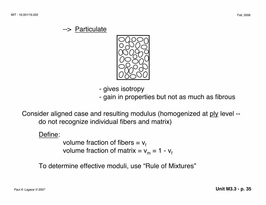
--> Particulate
- gives isotropy- gain in properties but not as much as fibrous
Consider aligned case and resulting modulus (homogenized at ply level -- do not recognize individual fibers and matrix)
Define:volume fraction of fibers = vfvolume fraction of matrix = vm = 1 - vf
To determine effective moduli, use “Rule of Mixtures”

Unit M3.3 - p. 36Paul A. Lagace © 2007
MIT - 16.001/16.002 Fall, 2008
--> along fibers:- fibers are stiff springs, matrix is soft springs.- bonded well together so they deform same amount (combined action)
Figure M3.3-20 Model of fibers and matrix as springs in parallel
F
F
fiber matrix

Unit M3.3 - p. 37Paul A. Lagace © 2007
MIT - 16.001/16.002 Fall, 2008
results in: εfiber = εmatrix
So:
longitudinal(parallel to fibers)
σ total = σ fiber vf + σ matrix 1 − vf( )= Efiber ε vf + Ematrix ε 1 − vf( )
⇒ ELcomp = σε
= Ef v f + Em 1− v f( )
Rule of Mixtures is a weighted average(same for density)
Unit M3.3 - p. 38Paul A. Lagace © 2007
MIT - 16.001/16.002 Fall, 2008
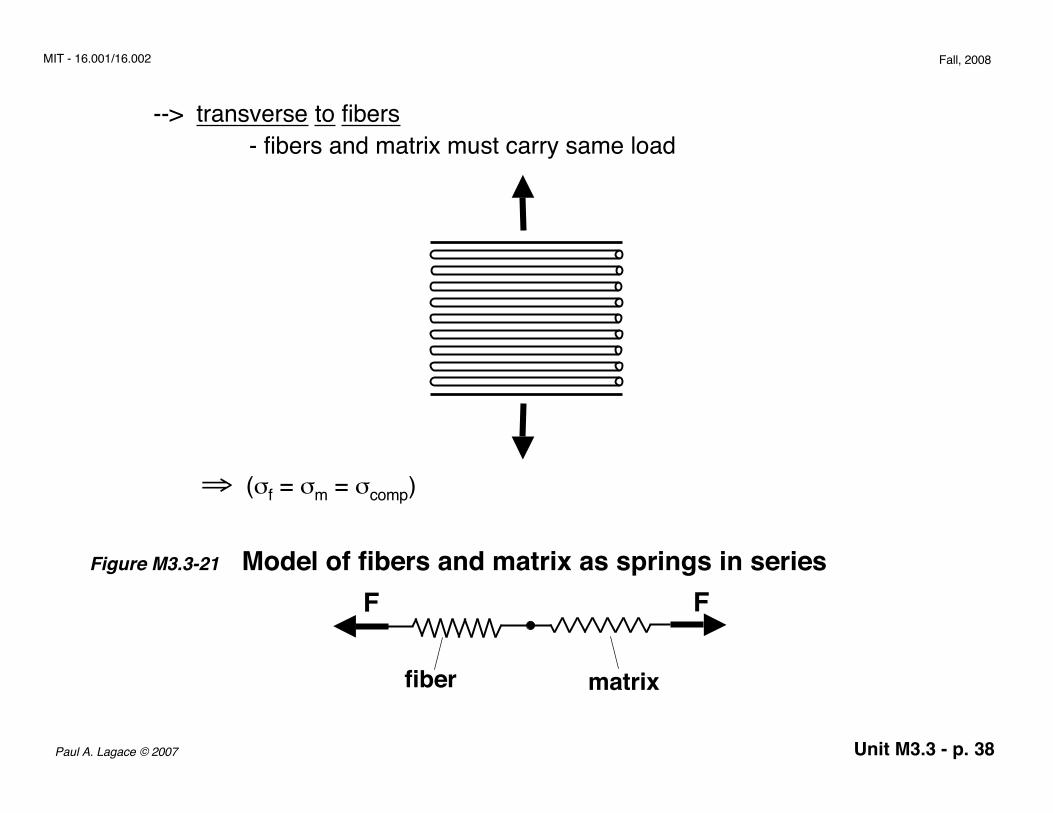
--> transverse to fibers- fibers and matrix must carry same load
⇒ (σf = σm = σcomp)
Figure M3.3-21 Model of fibers and matrix as springs in series
fiber matrix
FF

Unit M3.3 - p. 39Paul A. Lagace © 2007
MIT - 16.001/16.002 Fall, 2008
total strain is sum of two strains (deformation) weighted by fraction of each:
transverse(perpendicular to fibers)
Note the very large (potentially) difference between the two values(orthotropy).Depends on: Ef
EmVf
Now that we’ve looked at the (micro) structure of materials, let’s go back and lookat our description of the macroscopic stress-strain behavior and explain it basedon the microstructure.
εcomp = vf ε f + vmεm
⇒ εcomp = v fσcomp
E f
+ 1 − vf( ) σ comp
Em
ETcomp = 1vfEf
+ 1− v f( )Em
= Ef Em
Emv f + Ef 1− v f( )


![Unit 1 Unit 2 Unit 3 Unit 4 Unit 5 Unit 6 Unit 7 Unit 8 ... 5 - Formatted.pdf · Unit 1 Unit 2 Unit 3 Unit 4 Unit 5 Unit 6 ... and Scatterplots] Unit 5 – Inequalities and Scatterplots](https://img.pdfslide.us/doc/110x75/5b76ea0a7f8b9a4c438c05a9/unit-1-unit-2-unit-3-unit-4-unit-5-unit-6-unit-7-unit-8-5-formattedpdf.jpg)