Embed Size (px)
Citation preview

Paul A. Lagace © 2007
MIT - 16.001/16.002 Fall, 2008
16.001/002 -- “Unified Engineering”Department of Aeronautics and Astronautics
Massachusetts Institute of Technology
Unit M1.4(All About)
Trusses
Readings:CDL 1.9

Unit M1.4 - p. 2Paul A. Lagace © 2007
MIT - 16.001/16.002 Fall, 2008
LEARNING OBJECTIVES FOR UNIT M1.4
Through participation in the lectures, recitations, and workassociated with Unit M1.4, it is intended that you will beable to………
• ….model a truss structure through the use of a FreeBody Diagram
• ….calculate the reaction forces for a staticallydeterminate truss structure
• ….determine the loads carried in each bar of a trussthrough the use of the Method of Joints and theMethod of Sections

Unit M1.4 - p. 3Paul A. Lagace © 2007
MIT - 16.001/16.002 Fall, 2008
A truss is a very useful structural configuration in which barsare connected at joints and the overall configuration carriesload through axial force in the bars.
Uses of trusses
Generally trusses are three-dimensional (3-D) although, they can bereduced to two-dimensional (2-D) form as we shall see…..
Figure M1.4-1 Bridges Figure M1.4-2 Buildings
• Cranes• Others?

Unit M1.4 - p. 4Paul A. Lagace © 2007
MIT - 16.001/16.002 Fall, 2008
Figure M1.4-3 Early days of aircraft
main load carrying members covered by light skinNow: semi-monocoque (egg shell)
--> load-carrying members with load-carrying skin• Space station, other space structure
As previously noted, these are generally 3-D, but let’sconsider the
Idealized Planar Truss
(concepts and techniques developed here can beextended/applied to the 3-D case)

Unit M1.4 - p. 5Paul A. Lagace © 2007
MIT - 16.001/16.002 Fall, 2008
Let’s first define an idealized planar truss (this is a model)1. All bars are straight2. Bar joints are frictionless pins3. Bars are massless and perfectly rigid (for loading
analysis)4. All loads and reactions are applied at the joints5. Loads in members are colinear (axial -- aligned with long
axis of bar)Thus:
Bars carry only axial forcesFigure M1.4-4 Consideration of load transfer at pin
Fbar_
Fpin_
Fbar_ Fpin_= (by equilibrium)

Unit M1.4 - p. 6Paul A. Lagace © 2007
MIT - 16.001/16.002 Fall, 2008
Pin bears or pulls on bar and only axial force can result
So we now “have” an idealized planar truss.
The first step in the analysis is…..
Determination of reactions
The fact that the structural body is a truss does not change the procedure:- Draw Force Body Diagram- Is it Statically Determinate (?)- If so, proceed, if not…(wait til future units!)- Apply planar equations of equilibrium
(purpose of analysis: determine reaction forces and the internal load/forces in bars)

Unit M1.4 - p. 7Paul A. Lagace © 2007
MIT - 16.001/16.002 Fall, 2008
Figure M1.4-5 Example of a “simplest” truss (3-member)
C
200 N
B
A
5 m
10 m
--> Draw FBDx2
x1
C
200 N
10 m
5 m
~
~
H A
H BVB~
- Is this statically determinate?YES 3 reactions = 3 degrees of freedom
(lateral in x1, lateral in x2, rotation about x3)

Unit M1.4 - p. 8Paul A. Lagace © 2007
MIT - 16.001/16.002 Fall, 2008
=> Proceed- Apply planar equations of equilibrium:
3 (3 degrees of freedom = 3 reactions)
+
+
+
⇒ HB = 400Nabout point A
And using gives:F1∑ = 0 ⇒ HA + HB = 0
F2∑ = 0 ⇒ vB + 200N = 0Summarizing:
F1∑ = 0 ⇒ HA + HB = 0
F2∑ = 0 ⇒ VB + 200N = 0
HA = − 400N
M3(A )∑
⇒VB = − 200N⇒ (200N)(10 m) − HB 5 m( ) = 0
HA = − 400NHB = 400NVB = − 200N

Unit M1.4 - p. 9Paul A. Lagace © 2007
MIT - 16.001/16.002 Fall, 2008
Figure M1.4-6 Redrawing Free Body Diagram with reactions determined
x2
x1
200 N
C
200 N
10 m
5 m
~
~
~
400 N
400 N
A
B
check by taking …must also be zero+
√ checks
Once the reactions are determined, we move on to determining theinternal forces in the bars.
M3(B)∑− 400N( )(5 m) + 200N( )(10 m) = 0
These are two methods:- Method of Joints- Method of Sections

Unit M1.4 - p. 10Paul A. Lagace © 2007
MIT - 16.001/16.002 Fall, 2008
Let’s first explore the…
Method of JointsBasically isolate each joint and draw a free body diagram and analyze it.Work progressively along the truss.
So once reactions are known, the procedure is:- isolate a joint by “cutting” bars- “replace” “cut” bars by tensile internal forces pulling away from joint coincident with bar- calculate and show orthogonal components of force for each bar (use geometry)- apply equations of planar equilibrium- positive forces are tensile; negative forces are compressive
--> do this at joints progressively from end of truss
This is best illustrated through an example…

Unit M1.4 - p. 11Paul A. Lagace © 2007
MIT - 16.001/16.002 Fall, 2008
Figure M1.4-7 Example of 3-bar truss (from before)x2
x1
200 N
C
200 N
10 m
5 m
~
~
400 N
400 N
A
B
Start by “isolating” joint C
~Recall:
on a bar represents a “cut”~
So we “cut” bars CB and CA and “replace” them by their associatedinternal forces FCB and FCA.
Figure M1.4-8 Isolation of joint Cx2
x1
C
200 N
~~FCA
FCB

Unit M1.4 - p. 12Paul A. Lagace © 2007
MIT - 16.001/16.002 Fall, 2008
FCB is at an angle. Thus, need to find components along x1 and x2Using geometry:
5 m
10 m
θ
θ = tan −1 5m10m
Figure M1.4-9 Geometry of angle of bars (at joint C)
x2
x1
C
200 N
~~
FCA
FCB 0.45 FCB
0.89 FCB
Figure M1.4-10 Redrawing of joint C with components of FCB illustrated
⇒ tan −1 12
≈ 27°
⇒ x1 − component of FCB = FCB cos 27° = 0.89 FCB⇒ x2 − component of FCB = FCB cos 27° = 0.45 FCBsin

Unit M1.4 - p. 13Paul A. Lagace © 2007
MIT - 16.001/16.002 Fall, 2008
--> Now apply planar equilibrium
F1∑ ⇒ − 0.89 FCB − FCA = 0
F2∑ ⇒ 0.45 FCB + 200N = 0⇒ FCB = − 444NM3∑ Nothing creates moment about joints!
+
+
+
F1∑ ⇒ − 0.89 FCB − FCA = 0
F2∑ ⇒ 0.45 FCB + 200N = 0
Using FCB in gives:F1∑ FCA = 395N
Figure M1.4-11 Redrawing of joint C with values of force
x2
x1C
200 N
~~
444 N
395 N
C
200 N
~~
– 444 N
395 Nor
compression sincearrow points in
Unit M1.4 - p. 14Paul A. Lagace © 2007
MIT - 16.001/16.002 Fall, 2008
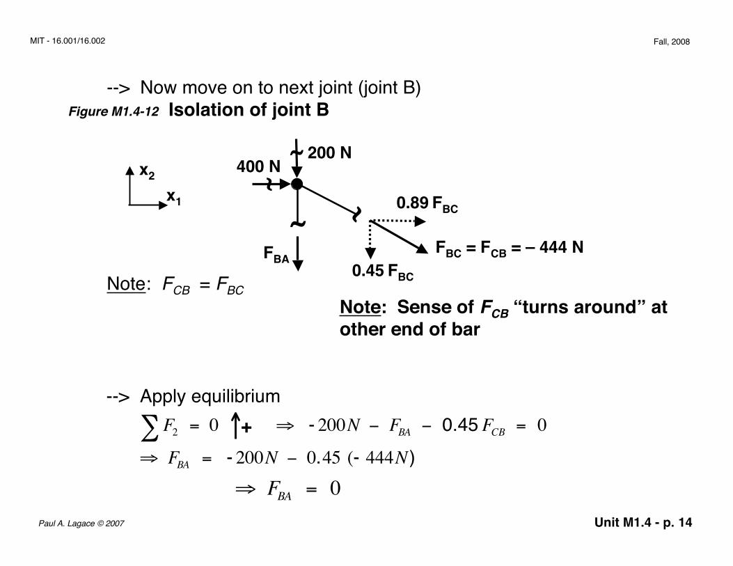
Figure M1.4-12 Isolation of joint B
x2
x1
200 N
~400 N
~ ~
FBC = FCB = – 444 NFBA
0.89 FBC
0.45 FBC
~
Note: FCB = FBCNote: Sense of FCB “turns around” atother end of bar
--> Apply equilibrium+
⇒ FBA = 0
--> Now move on to next joint (joint B)
F2∑ = 0 ⇒ - 200N − FBA − 0.45 FCB = 0⇒ FBA = - 200N − 0.45 (- 444N)

Unit M1.4 - p. 15Paul A. Lagace © 2007
MIT - 16.001/16.002 Fall, 2008
Check using
Have all bar loads, but use final joint as a check⇒ 400N − 390N = 0
Figure M1.4-13 Isolation of joint A
~400 N
A
x2
x1 ~~
FAC = 395 N
FAB = 0 N
By inspection, is this in equilibrium?F1∑ gives: 395N − 400N = − 5N
Why?
F1∑ = 0 ⇒ 400N + 0.89 FBC( ) = 0⇒ 400N + 0.89 −444N( ) = 0
?+
?
?

Unit M1.4 - p. 16Paul A. Lagace © 2007
MIT - 16.001/16.002 Fall, 2008
Finally, draw truss with bar forces written above corresponding bar(+) tension(–) compression
Figure M1.4-14 Representation of truss with all bar loads
x2
x1
200 N
C10 m
5 m~
~
400 N
400 N
~
200 N0 N– 444 N
395 N(~ 400 N)
--> Also notice that bar forces are much like the Rij forces we used in Unit U4 when considering a group of particles
This worked quite well for a truss with only a few bars or if we want theload in each bar, then we march progressively through the truss.

Unit M1.4 - p. 17Paul A. Lagace © 2007
MIT - 16.001/16.002 Fall, 2008
But, what if we have a bigger truss (one with more members/”bays”) andwe want only one of few bar loads? Go to the….
Method of Sections
Uses equilibrium of a section of the truss which contains two or morejoints.
Again, begin by determining reactions, then isolate a section by….- “cutting” the truss into sections (take a cut through the truss)- (again) “replace” “cut” bars by tensile internal forces pulling away from joint coincident with bar- (again) calculate and show orthogonal components of force for each bar (use geometry)- (again) apply equations of planar equilibrium- (again) positive forces are tensile; negative forces are compressive
Unit M1.4 - p. 18Paul A. Lagace © 2007
MIT - 16.001/16.002 Fall, 2008
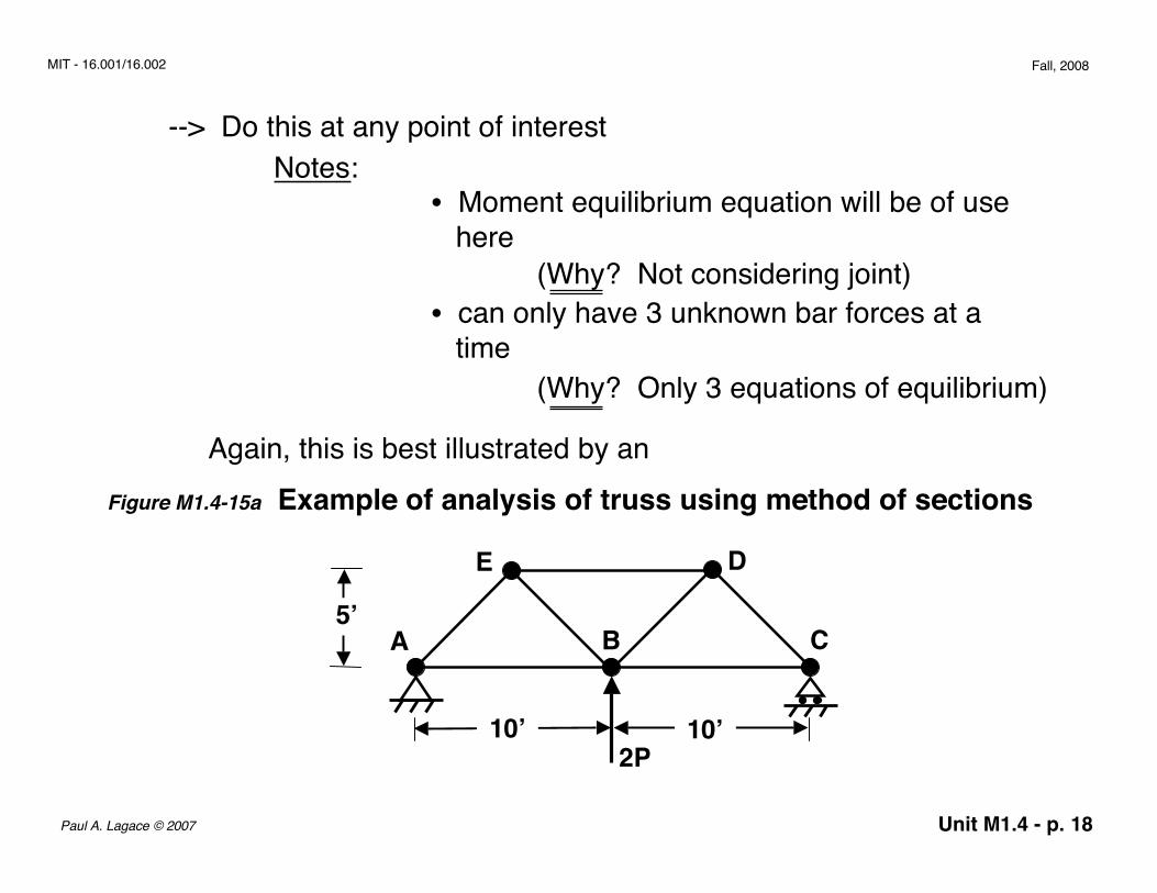
--> Do this at any point of interestNotes:
• Moment equilibrium equation will be of use here
(Why? Not considering joint)• can only have 3 unknown bar forces at a time
(Why? Only 3 equations of equilibrium)
Again, this is best illustrated by anFigure M1.4-15a Example of analysis of truss using method of sections
2P
A C
E
B
D
10’ 10’
5’

Unit M1.4 - p. 19Paul A. Lagace © 2007
MIT - 16.001/16.002 Fall, 2008
First draw Free Body Diagram
2P
A C
E
B
D
10’ 10’
5’
x2
x1
~
H A ~VA~ VC
Solving for the reactions:
+
+
+
⇒ VC = − P “about point A”
We are interested in bar EB, so we redraw the Free Body Diagramand take an appropriate “cut”
From F2 VA∑ = − P
F1∑ = 0 ⇒ HA = 0
F2∑ = 0 ⇒ VA + VC + 2P = 0
M3(A ) = 0∑ ⇒ 2P 10'( ) + VC 20'( ) = 0
Unit M1.4 - p. 20Paul A. Lagace © 2007
MIT - 16.001/16.002 Fall, 2008
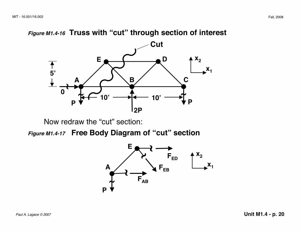
Figure M1.4-16 Truss with “cut” through section of interest
2P
A C
E
B
D
10’ 10’
5’
x2
x1
~
~
~
P
~
P
Cut
0
Now redraw the “cut” section:Figure M1.4-17 Free Body Diagram of “cut” section
A
E
~
P
~~
~
FAB
FEB
FEDx2
x1

Unit M1.4 - p. 21Paul A. Lagace © 2007
MIT - 16.001/16.002 Fall, 2008
Find the components of FEB:Figure M1.4-18 Use of geometry to determine components of FEB
5’θ
5’gives: θ = 45°
FEB
θFEB cos θ
FEB sin θ
So:Figure M1.4-19 Free Body Diagram of “cut” section with resolution of FEB
A
E
~
P
~~
~
FAB
FEB
FED x2
x10.707 FEB
0.707 FEB

Unit M1.4 - p. 22Paul A. Lagace © 2007
MIT - 16.001/16.002 Fall, 2008
Now use the equations of equilibrium:
+
+
+
and
chose E to isolate FEB ⇒ FAB = − P
Using these results in gives:F1∑-P - P + FED = 0
So can show:
F1∑ = 0 ⇒ FAB + 0.707 FEB + FED = 0
F2∑ = 0 ⇒ − P − 0.707 FEB = 0⇒ FEB = −1.414 P
M3(E ) = 0∑ ⇒ FAB 5'( ) + P 5'( ) = 0
⇒ FED = + 2P

Unit M1.4 - p. 23Paul A. Lagace © 2007
MIT - 16.001/16.002 Fall, 2008
Figure M1.4-20 Truss redrawn with loads for bars of interest
2P
A C
E
B
D x2
x1
~
P
~
P
2P
– P
– 1.414 P
Figure M1.4-21 Many possible “cuts” through truss depending upon section/bar(s) of interest
Can go on with more sections as desired.
etc.More generally can draw closed surface and consider all forces thatcross surface to get information…..

Unit M1.4 - p. 24Paul A. Lagace © 2007
MIT - 16.001/16.002 Fall, 2008
Figure M1.4-22 Illustration of closed surface drawn through truss and resulting free body diagram
2P
A C
E
B
D
10’ 10’
5’
x2
x1
~
~P
~P
0
2P
A B
D x2
x1
~
~
P
Closed surface“cut”
~ ~ ~~
~FAE
FBE
FDE
FDC
FBC
Unit M1.4 - p. 25Paul A. Lagace © 2007
MIT - 16.001/16.002 Fall, 2008
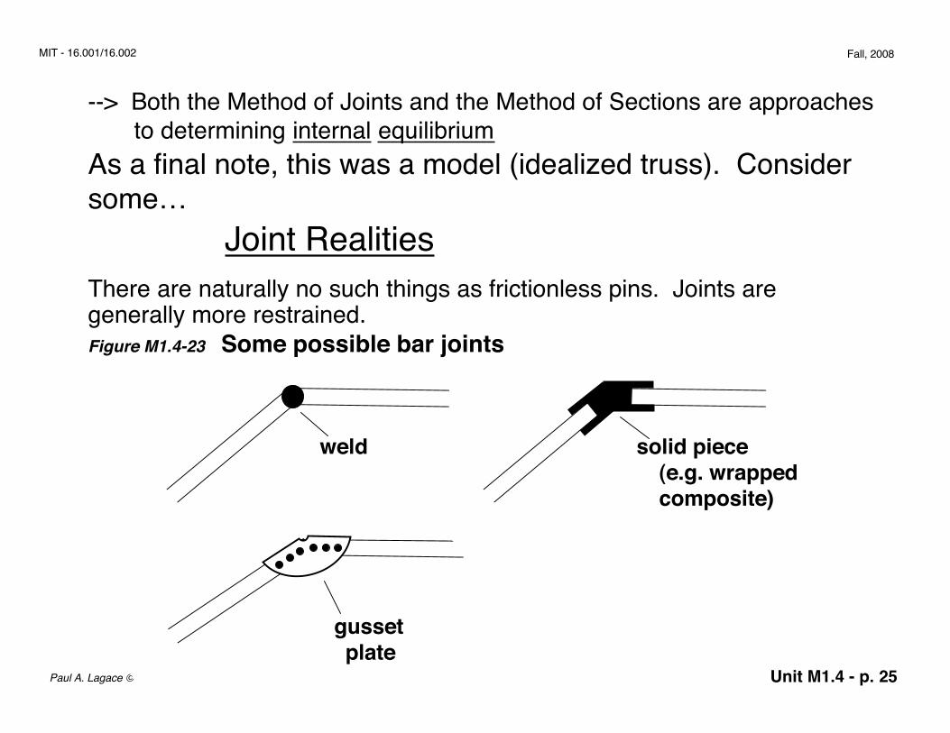
--> Both the Method of Joints and the Method of Sections are approaches to determining internal equilibriumAs a final note, this was a model (idealized truss). Considersome…
Joint RealitiesThere are naturally no such things as frictionless pins. Joints aregenerally more restrained.Figure M1.4-23 Some possible bar joints
weld
gussetplate
solid piece(e.g. wrappedcomposite)

Unit M1.4 - p. 26Paul A. Lagace © 2007
MIT - 16.001/16.002 Fall, 2008
Some space joints are closer to pinned in effect because bars(components) are long and slender
When the ends are constrained, moments can be taken and we mustalso consider beam behavior (more next term).
Joints are a key limitation of this idealized truss analysis
We’ve done a lot with equilibrium, but let’s now explore whathappens when we need more than equilibrium and deal withstatically indeterminate sections.