Embed Size (px)
Citation preview

Unit IIDesign of Footings
Home assignment
• Example: design a spiral column subjected to an unfactored load of 1600KN. Effective length of column is 3.5 m. Use M 25 and Fe 415.
Footings• Footings are structural members used to support columns and walls and to transmit and distribute
their loads to the soil in such a way that
• The load bearing capacity of the soil is not exceeded.
• Excessive settlement, differential settlement, or rotation are prevented and adequate safety against overturning or sliding is maintained.
• Types of footing
• Foundations are mainly of two types: (i) shallow foundations and (ii) deep foundations.
• Choice: depends upon
• Depth at which bearing strata lies
• Soil condition
• Type of superstructure
• Magnitude and type of reaction at the base of superstructure
• The soil type at site, the depth at which foundation can be laid and the safe load the soil can carry (B.C) have to be determined by a geotechnical consultant. Normally this information is available in a soil report.
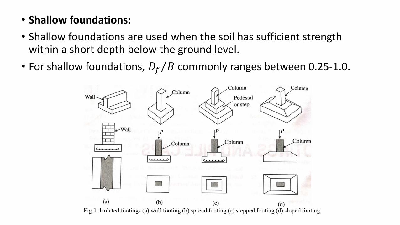
• Shallow foundations:
• Shallow foundations are used when the soil has sufficient strength within a short depth below the ground level.
• For shallow foundations, 𝐷𝑓 𝐵 commonly ranges between 0.25-1.0.
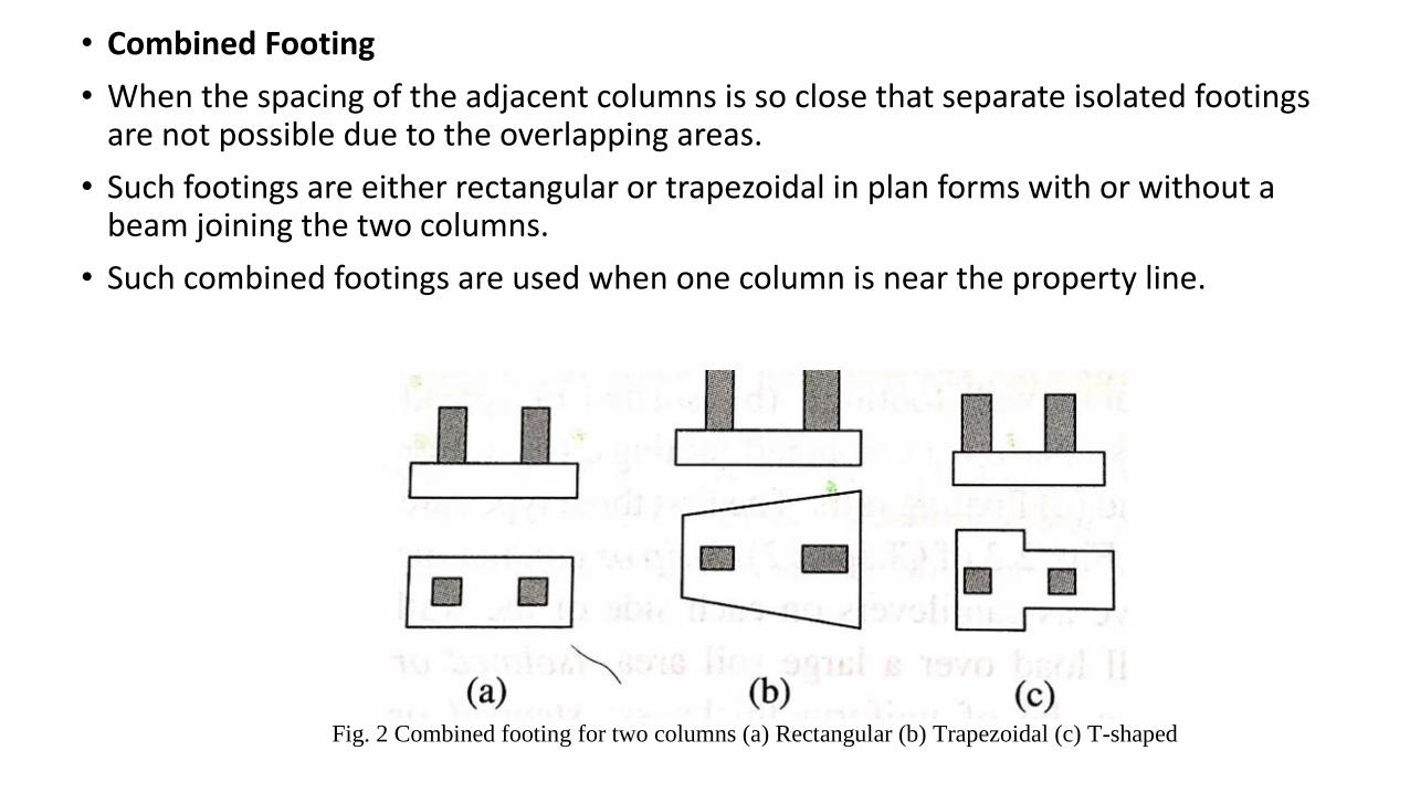
• Combined Footing
• When the spacing of the adjacent columns is so close that separate isolated footings are not possible due to the overlapping areas.
• Such footings are either rectangular or trapezoidal in plan forms with or without a beam joining the two columns.
• Such combined footings are used when one column is near the property line.
Fig. 2 Combined footing for two columns (a) Rectangular (b) Trapezoidal (c) T-shaped
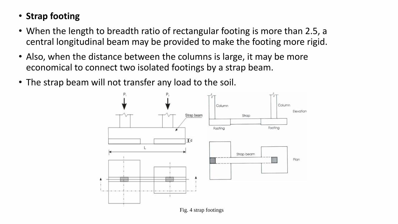
• Strap footing
• When the length to breadth ratio of rectangular footing is more than 2.5, a central longitudinal beam may be provided to make the footing more rigid.
• Also, when the distance between the columns is large, it may be more economical to connect two isolated footings by a strap beam.
• The strap beam will not transfer any load to the soil.
Fig. 4 strap footings
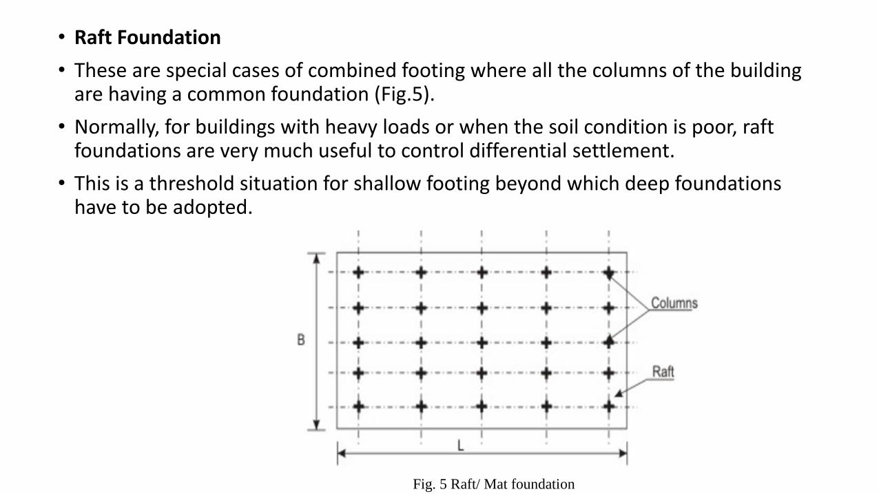
• Raft Foundation
• These are special cases of combined footing where all the columns of the building are having a common foundation (Fig.5).
• Normally, for buildings with heavy loads or when the soil condition is poor, raft foundations are very much useful to control differential settlement.
• This is a threshold situation for shallow footing beyond which deep foundations have to be adopted.
Fig. 5 Raft/ Mat foundation
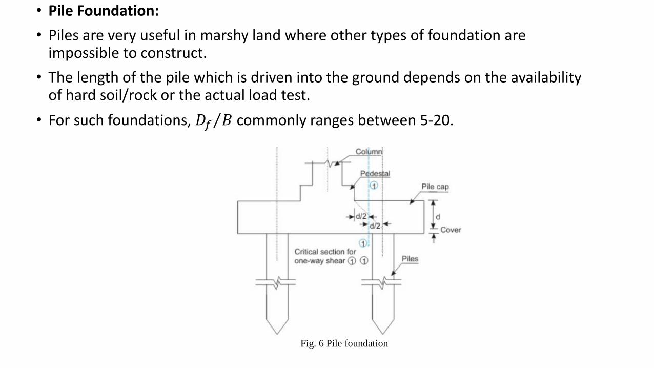
• Pile Foundation:
• Piles are very useful in marshy land where other types of foundation are impossible to construct.
• The length of the pile which is driven into the ground depends on the availability of hard soil/rock or the actual load test.
• For such foundations, 𝐷𝑓 𝐵 commonly ranges between 5-20.
Fig. 6 Pile foundation
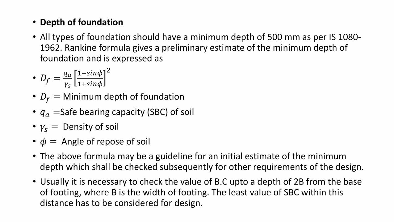
• Depth of foundation
• All types of foundation should have a minimum depth of 500 mm as per IS 1080-1962. Rankine formula gives a preliminary estimate of the minimum depth of foundation and is expressed as
• 𝐷𝑓 =𝑞𝑎
𝛾𝑠
1−𝑠𝑖𝑛𝜙
1+𝑠𝑖𝑛𝜙
2
• 𝐷𝑓 = Minimum depth of foundation
• 𝑞𝑎 =Safe bearing capacity (SBC) of soil
• 𝛾𝑠 = Density of soil
• 𝜙 = Angle of repose of soil
• The above formula may be a guideline for an initial estimate of the minimum depth which shall be checked subsequently for other requirements of the design.
• Usually it is necessary to check the value of B.C upto a depth of 2B from the base of footing, where B is the width of footing. The least value of SBC within this distance has to be considered for design.
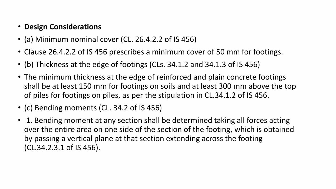
• Design Considerations
• (a) Minimum nominal cover (CL. 26.4.2.2 of IS 456)
• Clause 26.4.2.2 of IS 456 prescribes a minimum cover of 50 mm for footings.
• (b) Thickness at the edge of footings (CLs. 34.1.2 and 34.1.3 of IS 456)
• The minimum thickness at the edge of reinforced and plain concrete footings shall be at least 150 mm for footings on soils and at least 300 mm above the top of piles for footings on piles, as per the stipulation in CL.34.1.2 of IS 456.
• (c) Bending moments (CL. 34.2 of IS 456)
• 1. Bending moment at any section shall be determined taking all forces acting over the entire area on one side of the section of the footing, which is obtained by passing a vertical plane at that section extending across the footing (CL.34.2.3.1 of IS 456).
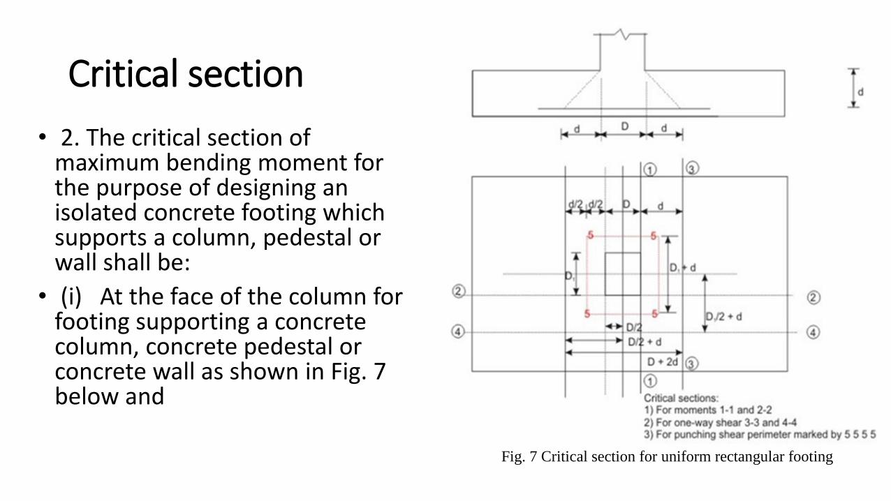
Critical section
• 2. The critical section of maximum bending moment for the purpose of designing an isolated concrete footing which supports a column, pedestal or wall shall be:
• (i) At the face of the column for footing supporting a concrete column, concrete pedestal or concrete wall as shown in Fig. 7 below and
Fig. 7 Critical section for uniform rectangular footing
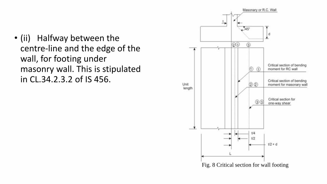
• (ii) Halfway between the centre-line and the edge of the wall, for footing under masonry wall. This is stipulated in CL.34.2.3.2 of IS 456.
Fig. 8 Critical section for wall footing
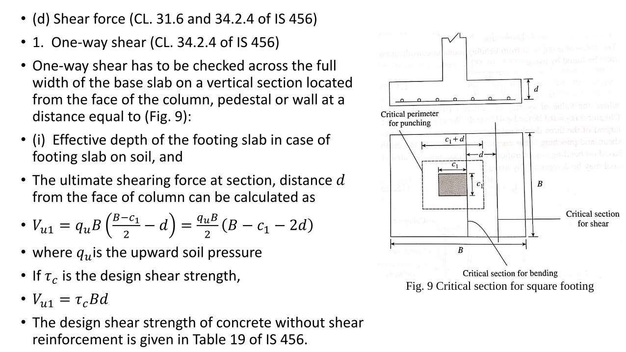
• (d) Shear force (CL. 31.6 and 34.2.4 of IS 456)
• 1. One-way shear (CL. 34.2.4 of IS 456)
• One-way shear has to be checked across the full width of the base slab on a vertical section located from the face of the column, pedestal or wall at a distance equal to (Fig. 9):
• (i) Effective depth of the footing slab in case of footing slab on soil, and
• The ultimate shearing force at section, distance 𝑑from the face of column can be calculated as
• 𝑉𝑢1 = 𝑞𝑢𝐵𝐵−𝑐1
2− 𝑑 =
𝑞𝑢𝐵
2𝐵 − 𝑐1 − 2𝑑
• where 𝑞𝑢is the upward soil pressure
• If 𝜏𝑐 is the design shear strength,
• 𝑉𝑢1 = 𝜏𝑐𝐵𝑑
• The design shear strength of concrete without shear reinforcement is given in Table 19 of IS 456.
Fig. 9 Critical section for square footing
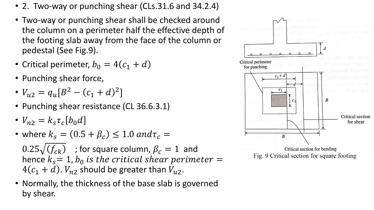
• 2. Two-way or punching shear (CLs.31.6 and 34.2.4)
• Two-way or punching shear shall be checked around the column on a perimeter half the effective depth of the footing slab away from the face of the column or pedestal (See Fig.9).
• Critical perimeter, 𝑏0 = 4 𝑐1 + 𝑑
• Punching shear force,
• 𝑉𝑢2 = 𝑞𝑢[𝐵2 − 𝑐1 + 𝑑 2]
• Punching shear resistance (CL 36.6.3.1)
• 𝑉𝑛2 = 𝑘𝑠𝜏𝑐 𝑏0𝑑
• where 𝑘𝑠 = 0.5 + 𝛽𝑐 ≤ 1.0 𝑎𝑛𝑑𝜏𝑐 =
0.25 𝑓𝑐𝑘 ; for square column, 𝛽𝑐 = 1 and hence 𝑘𝑠= 1, 𝑏0 𝑖𝑠 𝑡ℎ𝑒 𝑐𝑟𝑖𝑡𝑖𝑐𝑎𝑙 𝑠ℎ𝑒𝑎𝑟 𝑝𝑒𝑟𝑖𝑚𝑒𝑡𝑒𝑟 =4 𝑐1 + 𝑑 . 𝑉𝑛2 should be greater than 𝑉𝑢2.
• Normally, the thickness of the base slab is governed by shear.
• (e) Bond (CL.34.2.4.3 of IS 456)
• The critical section for checking the development length in a footing slab shall be the same planes as those of bending moments in part (c).
• (f) Tensile reinforcement (CL.34.3 of IS 456)
• (i) In one-way reinforced footing (wall footings), the reinforcement shall be distributed uniformly across the full width of the footing i.e., perpendicular to the direction of wall. Nominal distribution reinforcement shall be provided as per CL. 34.5 of IS 456 along the length of the wall.
• (ii) In two-way reinforced square footing, the reinforcement extending in each direction shall be distributed uniformly across the full width/length of the footing.
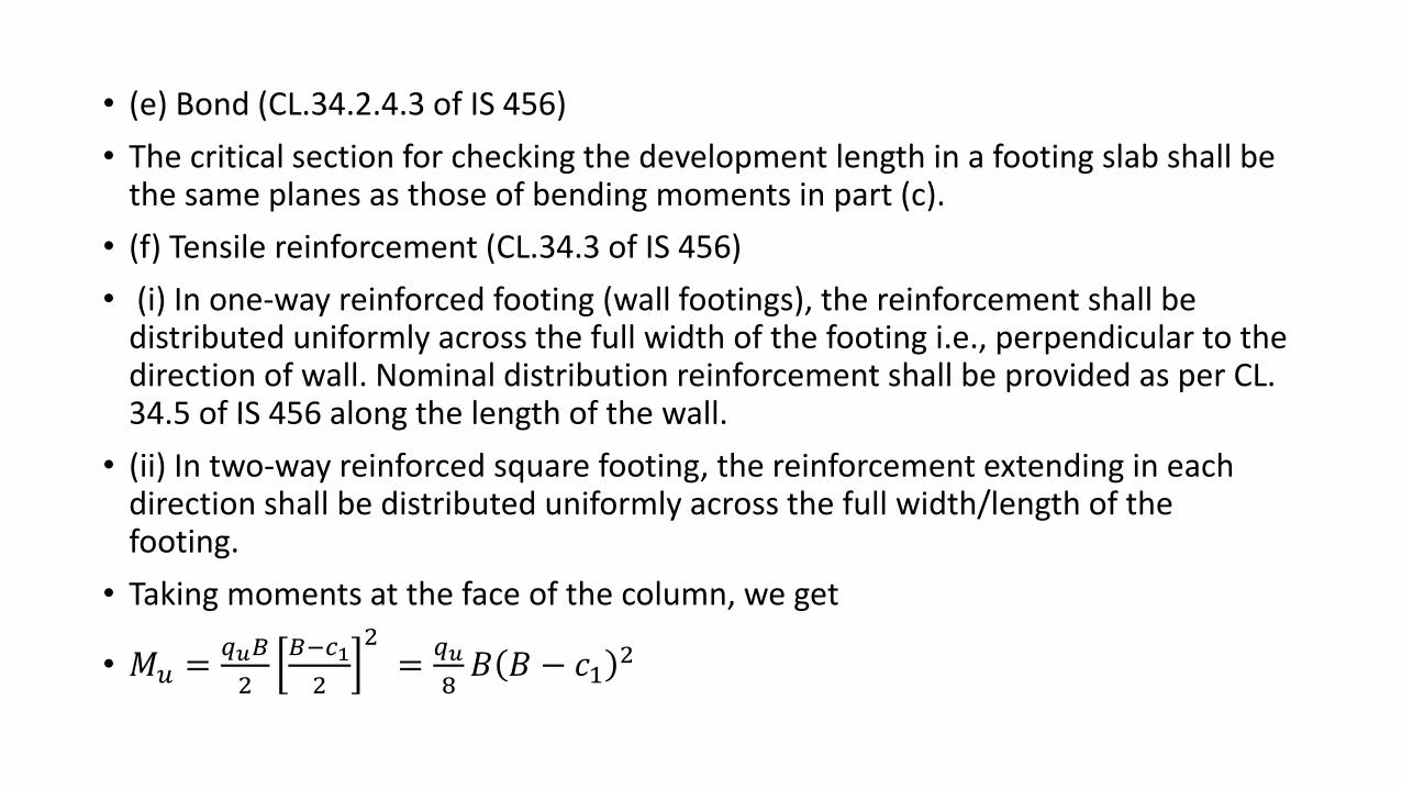
• Taking moments at the face of the column, we get
• 𝑀𝑢 =𝑞𝑢𝐵
2
𝐵−𝑐1
2
2=
𝑞𝑢
8𝐵 𝐵 − 𝑐1
2
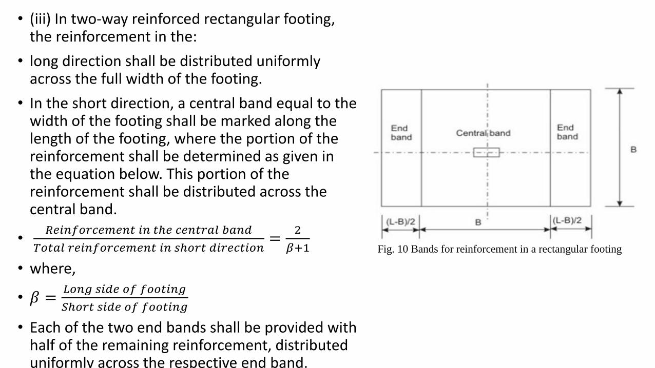
• (iii) In two-way reinforced rectangular footing, the reinforcement in the:
• long direction shall be distributed uniformly across the full width of the footing.
• In the short direction, a central band equal to the width of the footing shall be marked along the length of the footing, where the portion of the reinforcement shall be determined as given in the equation below. This portion of the reinforcement shall be distributed across the central band.
•𝑅𝑒𝑖𝑛𝑓𝑜𝑟𝑐𝑒𝑚𝑒𝑛𝑡 𝑖𝑛 𝑡ℎ𝑒 𝑐𝑒𝑛𝑡𝑟𝑎𝑙 𝑏𝑎𝑛𝑑
𝑇𝑜𝑡𝑎𝑙 𝑟𝑒𝑖𝑛𝑓𝑜𝑟𝑐𝑒𝑚𝑒𝑛𝑡 𝑖𝑛 𝑠ℎ𝑜𝑟𝑡 𝑑𝑖𝑟𝑒𝑐𝑡𝑖𝑜𝑛=
2
𝛽+1
• where,
• 𝛽 =𝐿𝑜𝑛𝑔 𝑠𝑖𝑑𝑒 𝑜𝑓 𝑓𝑜𝑜𝑡𝑖𝑛𝑔
𝑆ℎ𝑜𝑟𝑡 𝑠𝑖𝑑𝑒 𝑜𝑓 𝑓𝑜𝑜𝑡𝑖𝑛𝑔
• Each of the two end bands shall be provided with half of the remaining reinforcement, distributed uniformly across the respective end band.
Fig. 10 Bands for reinforcement in a rectangular footing
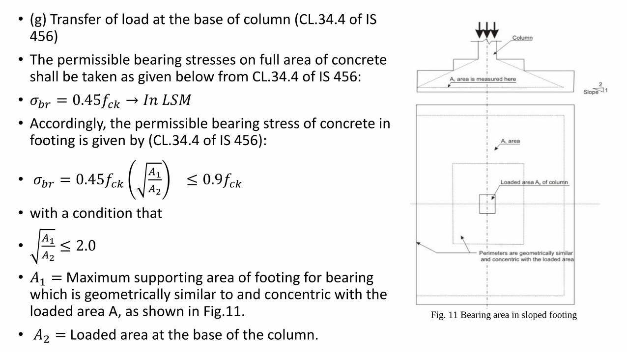
• (g) Transfer of load at the base of column (CL.34.4 of IS 456)
• The permissible bearing stresses on full area of concrete shall be taken as given below from CL.34.4 of IS 456:
• 𝜎𝑏𝑟 = 0.45𝑓𝑐𝑘 → 𝐼𝑛 𝐿𝑆𝑀
• Accordingly, the permissible bearing stress of concrete in footing is given by (CL.34.4 of IS 456):
• 𝜎𝑏𝑟 = 0.45𝑓𝑐𝑘𝐴1
𝐴2≤ 0.9𝑓𝑐𝑘
• with a condition that
•𝐴1
𝐴2≤ 2.0
• 𝐴1 = Maximum supporting area of footing for bearing which is geometrically similar to and concentric with the loaded area A, as shown in Fig.11.
• 𝐴2 = Loaded area at the base of the column.
Fig. 11 Bearing area in sloped footing
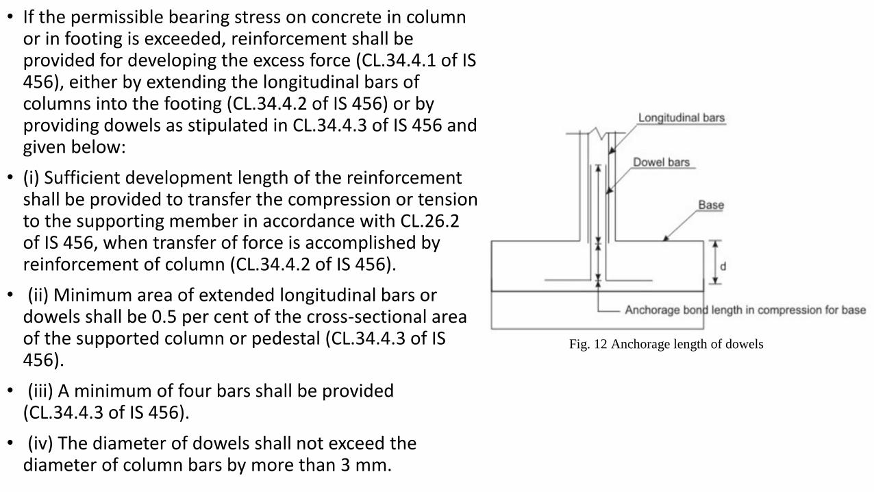
• If the permissible bearing stress on concrete in column or in footing is exceeded, reinforcement shall be provided for developing the excess force (CL.34.4.1 of IS 456), either by extending the longitudinal bars of columns into the footing (CL.34.4.2 of IS 456) or by providing dowels as stipulated in CL.34.4.3 of IS 456 and given below:
• (i) Sufficient development length of the reinforcement shall be provided to transfer the compression or tension to the supporting member in accordance with CL.26.2 of IS 456, when transfer of force is accomplished by reinforcement of column (CL.34.4.2 of IS 456).
• (ii) Minimum area of extended longitudinal bars or dowels shall be 0.5 per cent of the cross-sectional area of the supported column or pedestal (CL.34.4.3 of IS 456).
• (iii) A minimum of four bars shall be provided (CL.34.4.3 of IS 456).
• (iv) The diameter of dowels shall not exceed the diameter of column bars by more than 3 mm.
Fig. 12 Anchorage length of dowels
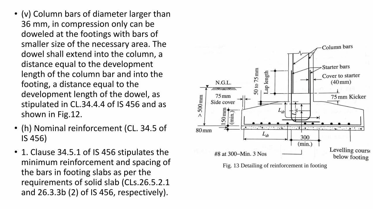
• (v) Column bars of diameter larger than 36 mm, in compression only can be doweled at the footings with bars of smaller size of the necessary area. The dowel shall extend into the column, a distance equal to the development length of the column bar and into the footing, a distance equal to the development length of the dowel, as stipulated in CL.34.4.4 of IS 456 and as shown in Fig.12.
• (h) Nominal reinforcement (CL. 34.5 of IS 456)
• 1. Clause 34.5.1 of IS 456 stipulates the minimum reinforcement and spacing of the bars in footing slabs as per the requirements of solid slab (CLs.26.5.2.1 and 26.3.3b (2) of IS 456, respectively).
Fig. 13 Detailing of reinforcement in footing
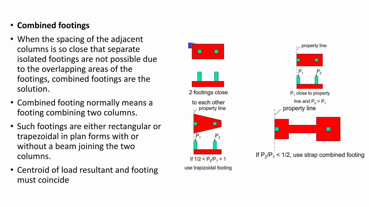
• Combined footings
• When the spacing of the adjacent columns is so close that separate isolated footings are not possible due to the overlapping areas of the footings, combined footings are the solution.
• Combined footing normally means a footing combining two columns.
• Such footings are either rectangular or trapezoidal in plan forms with or without a beam joining the two columns.
• Centroid of load resultant and footing must coincide
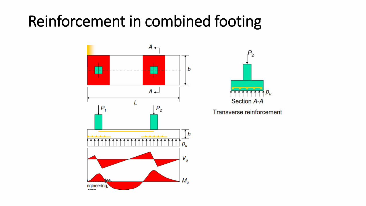
Reinforcement in combined footing
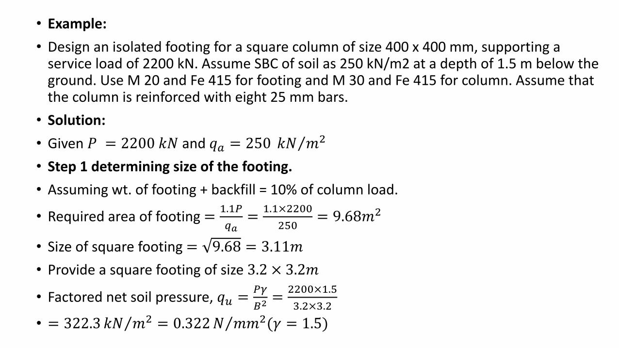
• Example:
• Design an isolated footing for a square column of size 400 x 400 mm, supporting a service load of 2200 kN. Assume SBC of soil as 250 kN/m2 at a depth of 1.5 m below the ground. Use M 20 and Fe 415 for footing and M 30 and Fe 415 for column. Assume that the column is reinforced with eight 25 mm bars.
• Solution:
• Given 𝑃 = 2200 𝑘𝑁 and 𝑞𝑎 = 250 𝑘𝑁 𝑚2
• Step 1 determining size of the footing.
• Assuming wt. of footing + backfill = 10% of column load.
• Required area of footing =1.1𝑃
𝑞𝑎=
1.1×2200
250= 9.68𝑚2
• Size of square footing = 9.68 = 3.11𝑚
• Provide a square footing of size 3.2 × 3.2𝑚
• Factored net soil pressure, 𝑞𝑢 =𝑃𝛾
𝐵2=
2200×1.5
3.2×3.2
• = 322.3 𝑘𝑁 𝑚2 = 0.322 𝑁 𝑚𝑚2(𝛾 = 1.5)
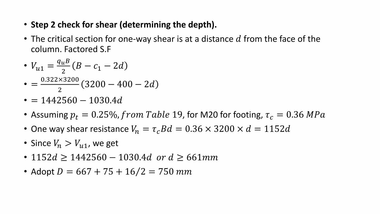
• Step 2 check for shear (determining the depth).
• The critical section for one-way shear is at a distance 𝑑 from the face of the column. Factored S.F
• 𝑉𝑢1 =𝑞𝑢𝐵
2𝐵 − 𝑐1 − 2𝑑
• =0.322×3200
23200 − 400 − 2𝑑
• = 1442560 − 1030.4𝑑
• Assuming 𝑝𝑡 = 0.25%, 𝑓𝑟𝑜𝑚 𝑇𝑎𝑏𝑙𝑒 19, for M20 for footing, 𝜏𝑐 = 0.36 𝑀𝑃𝑎
• One way shear resistance 𝑉𝑛 = 𝜏𝑐𝐵𝑑 = 0.36 × 3200 × 𝑑 = 1152𝑑
• Since 𝑉𝑛 > 𝑉𝑢1, we get
• 1152𝑑 ≥ 1442560 − 1030.4𝑑 𝑜𝑟 𝑑 ≥ 661𝑚𝑚
• Adopt 𝐷 = 667 + 75 + 16 2 = 750 𝑚𝑚
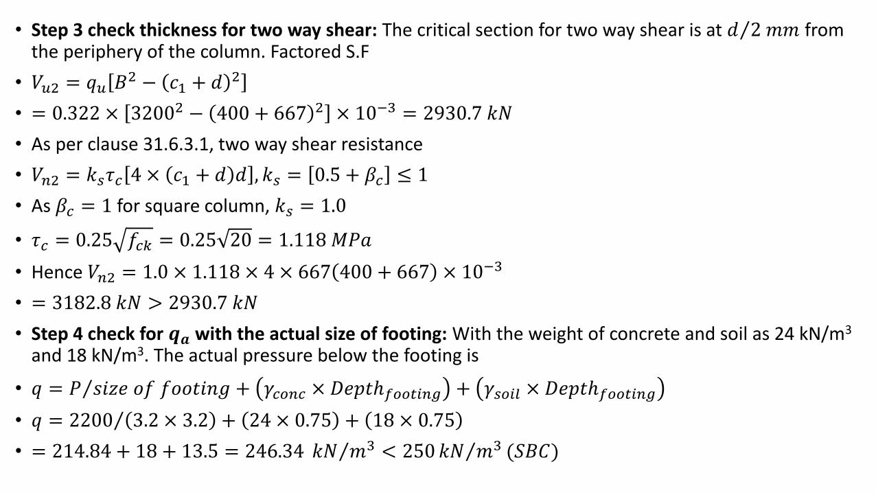
• Step 3 check thickness for two way shear: The critical section for two way shear is at 𝑑 2 𝑚𝑚 from the periphery of the column. Factored S.F
• 𝑉𝑢2 = 𝑞𝑢 𝐵2 − 𝑐1 + 𝑑 2
• = 0.322 × 32002 − 400 + 667 2 × 10−3 = 2930.7 𝑘𝑁
• As per clause 31.6.3.1, two way shear resistance
• 𝑉𝑛2 = 𝑘𝑠𝜏𝑐 4 × 𝑐1 + 𝑑 𝑑 , 𝑘𝑠 = 0.5 + 𝛽𝑐 ≤ 1
• As 𝛽𝑐 = 1 for square column, 𝑘𝑠 = 1.0
• 𝜏𝑐 = 0.25 𝑓𝑐𝑘 = 0.25 20 = 1.118 𝑀𝑃𝑎
• Hence 𝑉𝑛2 = 1.0 × 1.118 × 4 × 667 400 + 667 × 10−3
• = 3182.8 𝑘𝑁 > 2930.7 𝑘𝑁
• Step 4 check for 𝒒𝒂 with the actual size of footing: With the weight of concrete and soil as 24 kN/m3
and 18 kN/m3. The actual pressure below the footing is
• 𝑞 = 𝑃 𝑠𝑖𝑧𝑒 𝑜𝑓 𝑓𝑜𝑜𝑡𝑖𝑛𝑔 + 𝛾𝑐𝑜𝑛𝑐 × 𝐷𝑒𝑝𝑡ℎ𝑓𝑜𝑜𝑡𝑖𝑛𝑔 + 𝛾𝑠𝑜𝑖𝑙 × 𝐷𝑒𝑝𝑡ℎ𝑓𝑜𝑜𝑡𝑖𝑛𝑔
• 𝑞 = 2200 3.2 × 3.2 + 24 × 0.75 + 18 × 0.75
• = 214.84 + 18 + 13.5 = 246.34 𝑘𝑁 𝑚3 < 250 𝑘𝑁 𝑚3 (𝑆𝐵𝐶)
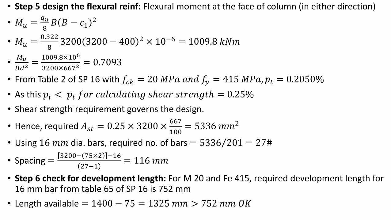
• Step 5 design the flexural reinf: Flexural moment at the face of column (in either direction)
• 𝑀𝑢 =𝑞𝑢
8𝐵 𝐵 − 𝑐1
2
• 𝑀𝑢 =0.322
83200 3200 − 400 2 × 10−6 = 1009.8 𝑘𝑁𝑚
•𝑀𝑢
𝐵𝑑2=
1009.8×106
3200×6672= 0.7093
• From Table 2 of SP 16 with 𝑓𝑐𝑘 = 20𝑀𝑃𝑎 𝑎𝑛𝑑 𝑓𝑦 = 415 𝑀𝑃𝑎, 𝑝𝑡 = 0.2050%
• As this 𝑝𝑡 < 𝑝𝑡 𝑓𝑜𝑟 𝑐𝑎𝑙𝑐𝑢𝑙𝑎𝑡𝑖𝑛𝑔 𝑠ℎ𝑒𝑎𝑟 𝑠𝑡𝑟𝑒𝑛𝑔𝑡ℎ = 0.25%
• Shear strength requirement governs the design.
• Hence, required 𝐴𝑠𝑡 = 0.25 × 3200 ×667
100= 5336 𝑚𝑚2
• Using 16 𝑚𝑚 dia. bars, required no. of bars = 5336 201 = 27#
• Spacing =3200− 75×2 −16
27−1= 116 𝑚𝑚
• Step 6 check for development length: For M 20 and Fe 415, required development length for 16 mm bar from table 65 of SP 16 is 752 mm
• Length available = 1400 − 75 = 1325 𝑚𝑚 > 752 𝑚𝑚 𝑂𝐾
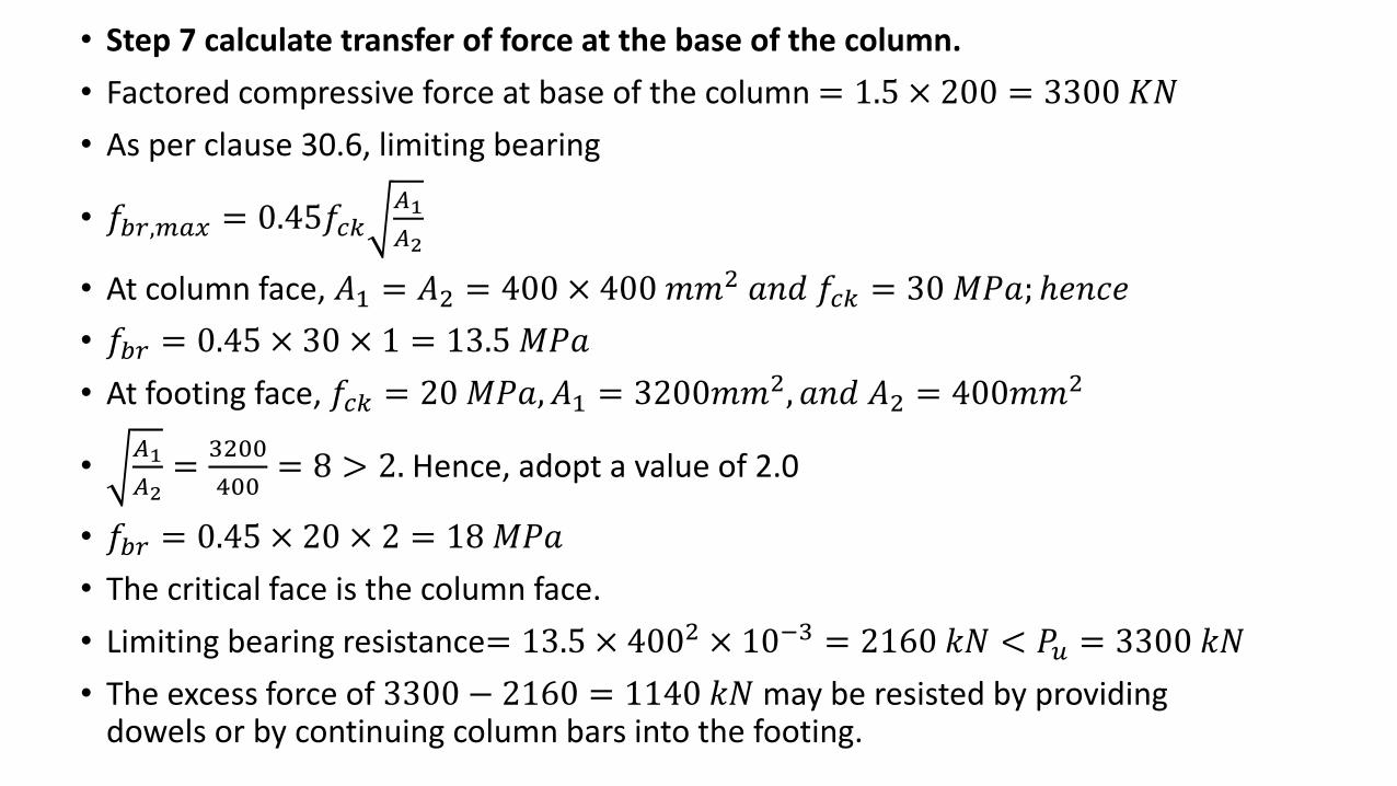
• Step 7 calculate transfer of force at the base of the column.
• Factored compressive force at base of the column = 1.5 × 200 = 3300 𝐾𝑁
• As per clause 30.6, limiting bearing
• 𝑓𝑏𝑟,𝑚𝑎𝑥 = 0.45𝑓𝑐𝑘𝐴1
𝐴2
• At column face, 𝐴1 = 𝐴2 = 400 × 400 𝑚𝑚2 𝑎𝑛𝑑 𝑓𝑐𝑘 = 30 𝑀𝑃𝑎; ℎ𝑒𝑛𝑐𝑒
• 𝑓𝑏𝑟 = 0.45 × 30 × 1 = 13.5 𝑀𝑃𝑎
• At footing face, 𝑓𝑐𝑘 = 20𝑀𝑃𝑎, 𝐴1 = 3200𝑚𝑚2, 𝑎𝑛𝑑 𝐴2 = 400𝑚𝑚2
•𝐴1
𝐴2=
3200
400= 8 > 2. Hence, adopt a value of 2.0
• 𝑓𝑏𝑟 = 0.45 × 20 × 2 = 18 𝑀𝑃𝑎
• The critical face is the column face.
• Limiting bearing resistance= 13.5 × 4002 × 10−3 = 2160 𝑘𝑁 < 𝑃𝑢 = 3300 𝑘𝑁
• The excess force of 3300 − 2160 = 1140 𝑘𝑁 may be resisted by providing dowels or by continuing column bars into the footing.
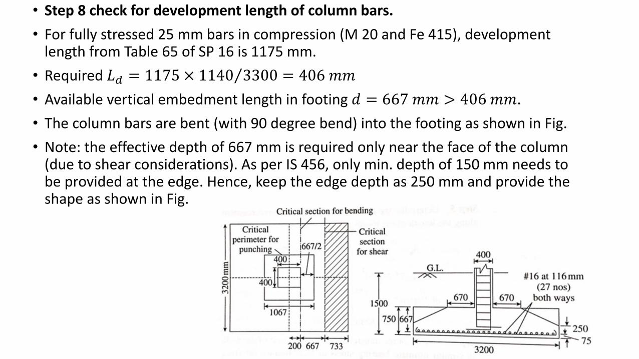
• Step 8 check for development length of column bars.
• For fully stressed 25 mm bars in compression (M 20 and Fe 415), development length from Table 65 of SP 16 is 1175 mm.
• Required 𝐿𝑑 = 1175 × 1140 3300 = 406 𝑚𝑚
• Available vertical embedment length in footing 𝑑 = 667 𝑚𝑚 > 406 𝑚𝑚.
• The column bars are bent (with 90 degree bend) into the footing as shown in Fig.
• Note: the effective depth of 667 mm is required only near the face of the column (due to shear considerations). As per IS 456, only min. depth of 150 mm needs to be provided at the edge. Hence, keep the edge depth as 250 mm and provide the shape as shown in Fig.