Embed Size (px)
DESCRIPTION
BERNOULLI’S THEOREM
Citation preview
Mohd Ashraf Mohd Ismail
Laboratory Experiment 2
Name : Mohammed Ashraf Bin Mohammed Ismail
Student No: N0806406
Contact No: 98225529
Date Submitted:
Lab. : BERNOULLI’S THEOREM
Course Instructor: Mr Roger Chua
2
Table of Contents
ABSTRACT .................................................................................................................. 3
INTRODUCTION ......................................................................................................... 4
OBJECTIVES................................................................................................................ 5
EXPIREMENT PROCEDURE ..................................................................................... 6
EXPIREMENT RESULT.............................................................................................. 7
TEST 1................................................................................................................... 7
TEST 2................................................................................................................... 8
TEST 3................................................................................................................... 9
DISCUSSION OF RESULT........................................................................................ 10
CONCLUSION............................................................................................................ 11
REFERENCE .............................................................................................................. 12
APPENDIX.................................................................................................................. 13
Introduction to Aerospace Engineering Lab 2
3
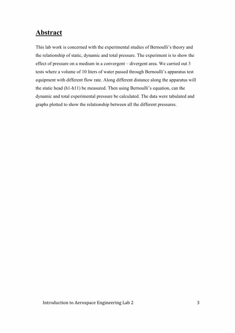
Abstract
This lab work is concerned with the experimental studies of Bernoulli’s theory and
the relationship of static, dynamic and total pressure. The experiment is to show the
effect of pressure on a medium in a convergent – divergent area. We carried out 3
tests where a volume of 10 liters of water passed through Bernoulli’s apparatus test
equipment with different flow rate. Along different distance along the apparatus will
the static head (h1-h11) be measured. Then using Bernoulli’s equation, can the
dynamic and total experimental pressure be calculated. The data were tabulated and
graphs plotted to show the relationship between all the different pressures.
4
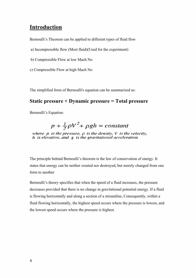
Introduction
Bernoulli’s Theorem can be applied to different types of fluid flow
a) Incompressible flow (Most fluid)(Used for the experiment)
b) Compressible Flow at low Mach No
c) Compressible Flow at high Mach No
The simplified form of Bernoulli's equation can be summarized as:
Static pressure + Dynamic pressure = Total pressure
Bernoulli’s Equation:
The principle behind Bernoulli’s theorem is the law of conservation of energy. It
states that energy can be neither created nor destroyed, but merely changed from one
form to another
Bernoulli’s theory specifies that when the speed of a fluid increases, the pressure
decreases provided that there is no change in gravitational potential energy. If a fluid
is flowing horizontally and along a section of a streamline, Consequently, within a
fluid flowing horizontally, the highest speed occurs where the pressure is lowest, and
the lowest speed occurs where the pressure is highest.
Introduction to Aerospace Engineering Lab 2
5
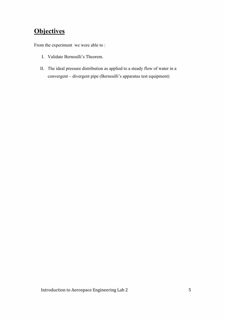
Objectives
From the experiment we were able to :
I. Validate Bernoulli’s Theorem.
II. The ideal pressure distribution as applied to a steady flow of water in a
convergent – divergent pipe (Bernoulli’s apparatus test equipment)
6
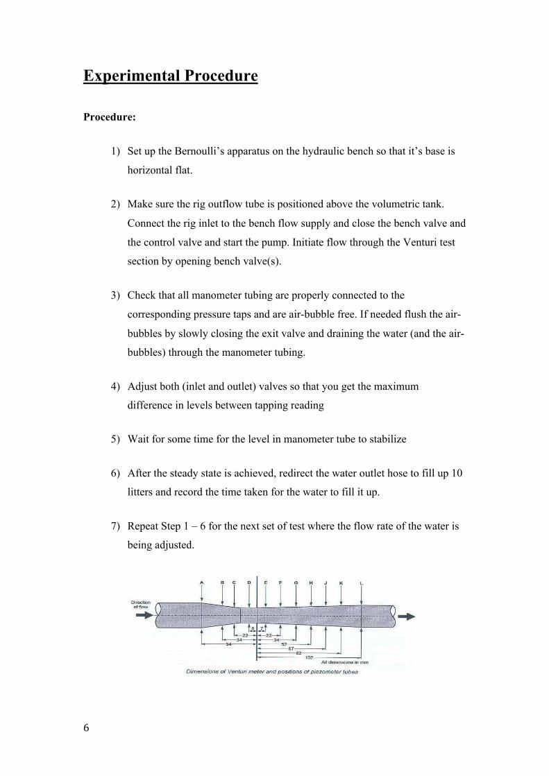
Experimental Procedure
Procedure:
1) Set up the Bernoulli’s apparatus on the hydraulic bench so that it’s base is
horizontal flat.
2) Make sure the rig outflow tube is positioned above the volumetric tank.
Connect the rig inlet to the bench flow supply and close the bench valve and
the control valve and start the pump. Initiate flow through the Venturi test
section by opening bench valve(s).
3) Check that all manometer tubing are properly connected to the
corresponding pressure taps and are air-bubble free. If needed flush the air-
bubbles by slowly closing the exit valve and draining the water (and the air-
bubbles) through the manometer tubing.
4) Adjust both (inlet and outlet) valves so that you get the maximum
difference in levels between tapping reading
5) Wait for some time for the level in manometer tube to stabilize
6) After the steady state is achieved, redirect the water outlet hose to fill up 10
litters and record the time taken for the water to fill it up.
7) Repeat Step 1 – 6 for the next set of test where the flow rate of the water is
being adjusted.
Introduction to Aerospace Engineering Lab 2
7
Test 1
8
Test2
Introduction to Aerospace Engineering Lab 2
9
Test 3

10
Discussion of Result
By the results form the 3 charts,
• As the flow of the water is changed
♦ Increase flow
Dynamic pressure increase, Static pressure decrease and total
pressure remain quite constant(+/-10%).
♦ Decreases flow
Dynamic pressure increase, Static pressure decrease and total
pressure remain quite constant(+/-10%).
• Change in Diameter
♦ Diameter Decrease
Dynamic pressure is increased, Static pressure decreases
♦ Diameter Increased
Dynamic pressure is decreased, Static pressure increased
• Difference between Theory and Experimental total Pressure.
The law of conservation of energy states that energy can be neither
created nor destroyed therefore the total pressure must be constant but
form our experiment; there is some room of error. Some of the factors
contributing to the error are
1) Friction – Friction between the water and the equipment.
2) Lost of power – Pump Efficiency affect the amount of water to be
pump constantly
3) Human Error – Improper set up of experiment, parallax error, and
calculation error
Introduction to Aerospace Engineering Lab 2
11
Conclusion
From the experiment we can conclude that Bernoulli’s Theorem is valid if these
certain assumption are being made
• Frictionless Motion
• Flow of fluid is constant (not fluncating)
• Fluid has a constant density
• No heat transfer along the streamline
• Potential energy of elevation remain constant (No Change in Height)
12
Reference
1. http://www.princeton.edu/~asmits/Bicycle_web/Bernoulli.html
2. http://classicairshows.com/Education/Aerodynamics/BernoulliAT1243.htm
3. http://acam.ednet.ns.ca/curriculum/wing.htm
4. http://en.wikipedia.org/wiki/Bernoulli's_principle
Introduction to Aerospace Engineering Lab 2
13
Appendix
14
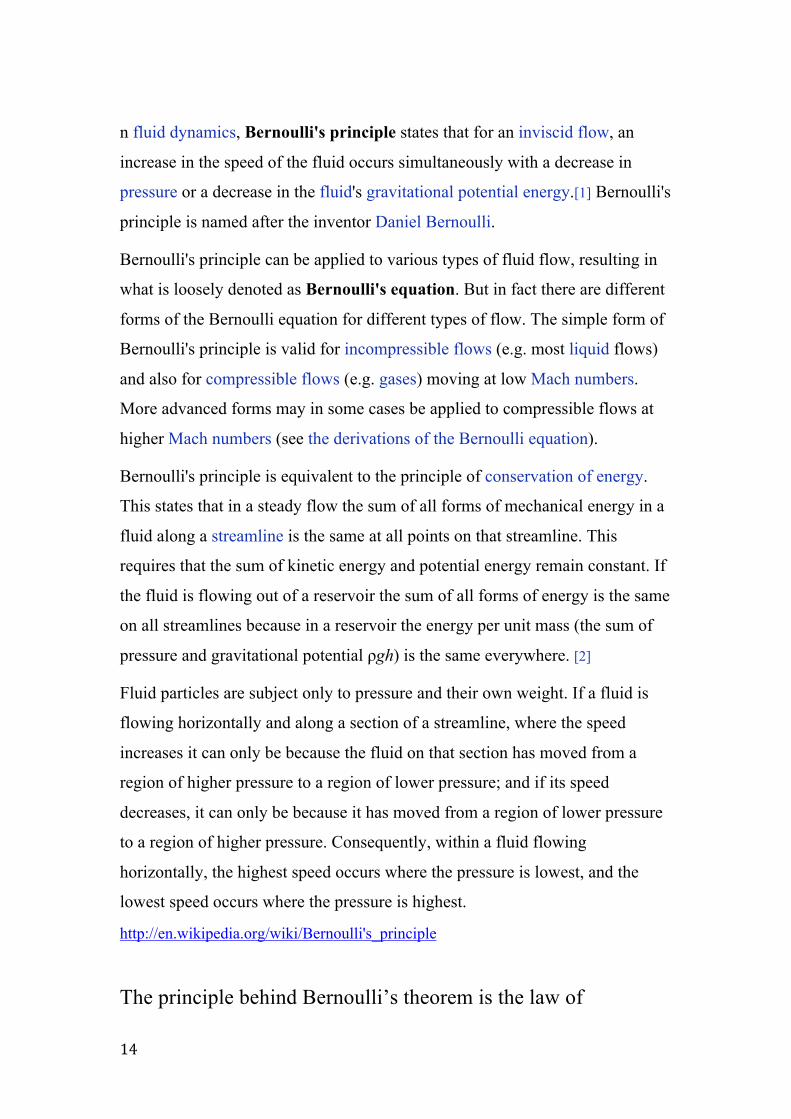
n fluid dynamics, Bernoulli's principle states that for an inviscid flow, an
increase in the speed of the fluid occurs simultaneously with a decrease in
pressure or a decrease in the fluid's gravitational potential energy.[1] Bernoulli's
principle is named after the inventor Daniel Bernoulli.
Bernoulli's principle can be applied to various types of fluid flow, resulting in
what is loosely denoted as Bernoulli's equation. But in fact there are different
forms of the Bernoulli equation for different types of flow. The simple form of
Bernoulli's principle is valid for incompressible flows (e.g. most liquid flows)
and also for compressible flows (e.g. gases) moving at low Mach numbers.
More advanced forms may in some cases be applied to compressible flows at
higher Mach numbers (see the derivations of the Bernoulli equation).
Bernoulli's principle is equivalent to the principle of conservation of energy.
This states that in a steady flow the sum of all forms of mechanical energy in a
fluid along a streamline is the same at all points on that streamline. This
requires that the sum of kinetic energy and potential energy remain constant. If
the fluid is flowing out of a reservoir the sum of all forms of energy is the same
on all streamlines because in a reservoir the energy per unit mass (the sum of
pressure and gravitational potential ρgh) is the same everywhere. [2]
Fluid particles are subject only to pressure and their own weight. If a fluid is
flowing horizontally and along a section of a streamline, where the speed
increases it can only be because the fluid on that section has moved from a
region of higher pressure to a region of lower pressure; and if its speed
decreases, it can only be because it has moved from a region of lower pressure
to a region of higher pressure. Consequently, within a fluid flowing
horizontally, the highest speed occurs where the pressure is lowest, and the
lowest speed occurs where the pressure is highest.
http://en.wikipedia.org/wiki/Bernoulli's_principle
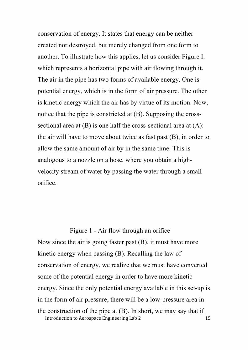
The principle behind Bernoulli’s theorem is the law of
Introduction to Aerospace Engineering Lab 2
15
conservation of energy. It states that energy can be neither
created nor destroyed, but merely changed from one form to
another. To illustrate how this applies, let us consider Figure I.
which represents a horizontal pipe with air flowing through it.
The air in the pipe has two forms of available energy. One is
potential energy, which is in the form of air pressure. The other
is kinetic energy which the air has by virtue of its motion. Now,
notice that the pipe is constricted at (B). Supposing the cross-
sectional area at (B) is one half the cross-sectional area at (A):
the air will have to move about twice as fast past (B), in order to
allow the same amount of air by in the same time. This is
analogous to a nozzle on a hose, where you obtain a high-
velocity stream of water by passing the water through a small
orifice.
Figure 1 - Air flow through an orifice
Now since the air is going faster past (B), it must have more
kinetic energy when passing (B). Recalling the law of
conservation of energy, we realize that we must have converted
some of the potential energy in order to have more kinetic
energy. Since the only potential energy available in this set-up is
in the form of air pressure, there will be a low-pressure area in
the construction of the pipe at (B). In short, we may say that if
16
air is flowing, other factors being equal, an increase in velocity
will result in a decrease in pressure; and conversely, a decrease
in velocity will result in an increase in pressure. It should be
noted that the pressure and velocity at (C) are the same as at (A).
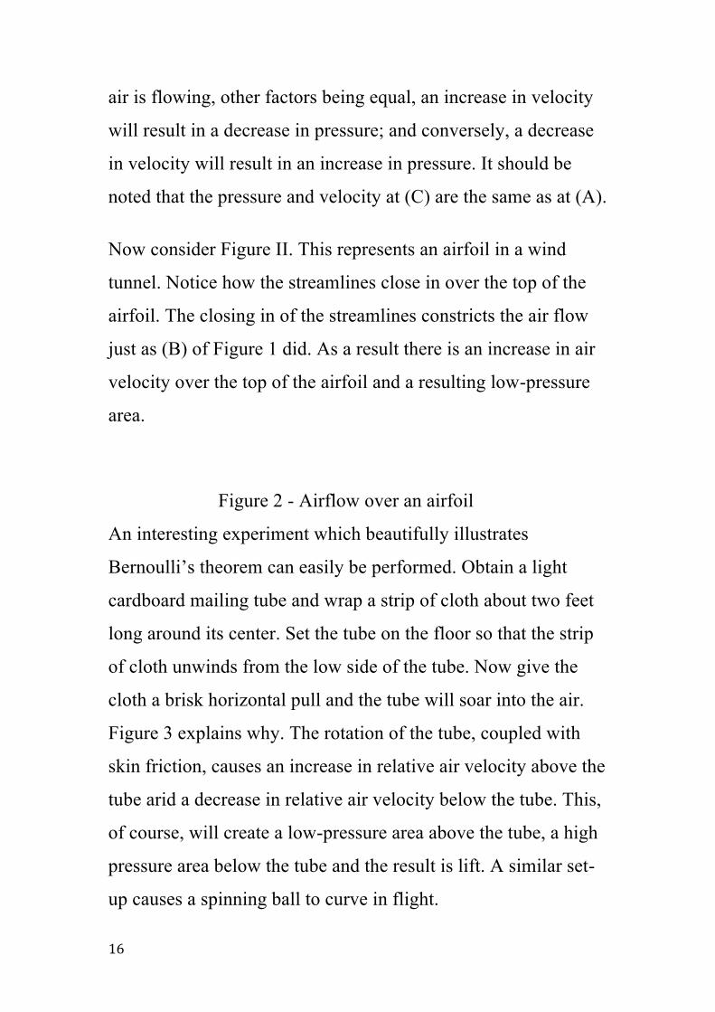
Now consider Figure II. This represents an airfoil in a wind
tunnel. Notice how the streamlines close in over the top of the
airfoil. The closing in of the streamlines constricts the air flow
just as (B) of Figure 1 did. As a result there is an increase in air
velocity over the top of the airfoil and a resulting low-pressure
area.
Figure 2 - Airflow over an airfoil
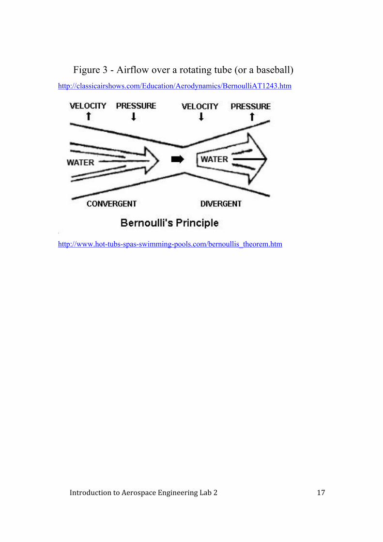
An interesting experiment which beautifully illustrates
Bernoulli’s theorem can easily be performed. Obtain a light
cardboard mailing tube and wrap a strip of cloth about two feet
long around its center. Set the tube on the floor so that the strip
of cloth unwinds from the low side of the tube. Now give the
cloth a brisk horizontal pull and the tube will soar into the air.
Figure 3 explains why. The rotation of the tube, coupled with
skin friction, causes an increase in relative air velocity above the
tube arid a decrease in relative air velocity below the tube. This,
of course, will create a low-pressure area above the tube, a high
pressure area below the tube and the result is lift. A similar set-
up causes a spinning ball to curve in flight.
Introduction to Aerospace Engineering Lab 2
17
Figure 3 - Airflow over a rotating tube (or a baseball) http://classicairshows.com/Education/Aerodynamics/BernoulliAT1243.htm
http://www.hot-tubs-spas-swimming-pools.com/bernoullis_theorem.htm
18
http://www.centennialofflight.gov/essay/Theories_of_Flight/Conservation/TH8G2.ht
m
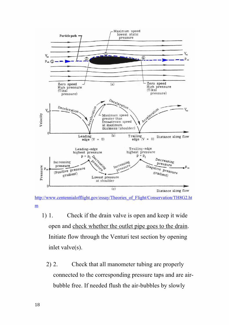
1) 1. Check if the drain valve is open and keep it wide
open and check whether the outlet pipe goes to the drain.
Initiate flow through the Venturi test section by opening
inlet valve(s).
2) 2. Check that all manometer tubing are properly
connected to the corresponding pressure taps and are air-
bubble free. If needed flush the air-bubbles by slowly
Introduction to Aerospace Engineering Lab 2
19
closing the exit valve and draining the water (and the air-
bubbles) through the manometer tubing.
3. Adjust both (inlet and outlet) valves so that you get
the maximum difference in levels between tapping point
#7 and #8.
4. Wait for some time for the level in manometer
tube #8 or #(*) to stabilize (it takes some time for it to
reach steady state).
5. After the steady state is achieved, redirect the
water outlet hose into a container whose capacity is
known (10 litters, for example) and record the time taken
for the water to fill it up. Take at least 3 measurements
and record the timings in order to calculate (average)
flow rate.
6. Gently push (slide) the Pitot (total head
measuring) tube, connected to manometer #8, so that its
end reaches the cross section of the Venturi tube at #1,
for example. Wait for some time and note down the
readings from manometer #8 (or *) and #1. The reading
shown by manometer #8(or *) is the sum of the pressure
and velocity heads, i.e. the total (or stagnation) head (h*),
because the Pitot tube is held against the flow of fluid
20
forcing it to a stop (zero velocity). The reading in
manometer #1 measures just the pressure head (h)
because it is connected to the Venturi tube pressure tap,
which does not obstruct the flow, thus measuring the
flow static pressure.
7. Repeat step 6 for other cross sections (3, 5, and 7, for
example).
http://www.ceet.niu.edu/faculty/kostic/bernoulli.html
ncompressible flow equation
In most flows of liquids, and of gases at low Mach number, the mass density of
a fluid parcel can be considered to be constant, regardless of pressure variations
in the flow. For this reason the fluid in such flows can be considered to be
incompressible and these flows can be described as incompressible flow.
Bernoulli performed his experiments on liquids and his equation in its original
form is valid only for incompressible flow.
The original form of Bernoulli's equation[3] is:
where:
is the fluid flow speed at a point on a streamline
is the acceleration due to gravity
is the height of the point above a reference plane
is the pressure at the point
is the density of the fluid at all points in the fluid
The following assumptions must be met for the equation to apply:
Introduction to Aerospace Engineering Lab 2
21
The fluid must be incompressible - even though pressure varies, the density
must remain constant.
The streamline must not enter the boundary layer. (Bernoulli's equation is not
applicable where there are viscous forces, such as in the boundary
layer.)
The above equation can be rewritten as:
where:
is dynamic pressure
The above equations suggest there is a flow speed at which pressure is zero and
at higher speeds the pressure is negative. Gases and liquids are not capable of
negative absolute pressure, or even zero pressure, so clearly Bernoulli's
equation ceases to be valid before zero pressure is reached. The above
equations use a linear relationship between flow speed squared and pressure.
At higher velocities in liquids, non-linear processes such as (viscous) turbulent
flow and cavitation occur. At higher flow speeds in gases the changes in
pressure become significant so that the assumption of constant density is
invalid.
[edit]
Simplified form
In several applications of Bernoulli's equation, the change in the term along
streamlines is zero or so small it can be ignored: for instance in the case of
airfoils at low Mach number. This allows the above equation to be presented in
the following simplified form:
where is called total pressure, and is dynamic pressure[4]. Many authors refer
to the pressure as static pressure to distinguish it from total pressure and

22
dynamic pressure . In Aerodynamics, L.J. Clancy writes: "To distinguish it
from the total and dynamic pressures, the actual pressure of the fluid, which is
associated not with its motion but with its state, is often referred to as the static
pressure, but where the term pressure alone is used it refers to this static
pressure."[5]
The simplified form of Bernoulli's equation can be summarized in the
following memorable word equation:
static pressure + dynamic pressure = total pressure[5]
Every point in a steadily flowing fluid, regardless of the fluid speed at that
point, has its own unique static pressure p, dynamic pressure q, and total
pressure p0.
The significance of Bernoulli's principle can now be summarized as "total
pressure is constant along a streamline." Furthermore, if the fluid flow
originated in a reservoir, the total pressure on every streamline is the same and
Bernoulli's principle can be summarized as "total pressure is constant
everywhere in the fluid flow." However, it is important to remember that
Bernoulli's principle does not apply in the boundary layer.
[edit]
Applicability of incompressible flow equation to flow of
gases
Bernoulli's equation is sometimes valid for the flow of gases provided that
there is no transfer of kinetic or potential energy from the gas flow to the
compression or expansion of the gas. If both the gas pressure and volume
change simultaneously, then work will be done on or by the gas. In this case,
Bernoulli's equation can not be assumed to be valid. However if the gas process
is entirely isobaric, or isochoric, then no work is done on or by the gas, (so the
simple energy balance is not upset). According to the gas law, an isobaric or
isochoric process is ordinarily the only way to ensure constant density in a gas.
Introduction to Aerospace Engineering Lab 2
23
Also the gas density will be proportional to the ratio of pressure and absolute
temperature, however this ratio will vary upon compression or expansion, no
matter what non-zero quantity of heat is added or removed. The only exception
is if the net heat transfer is zero, as in a complete thermodynamic cycle, or in
an individual isentropic (frictionless adiabatic) process, and even then this
reversible process must be reversed, to restore the gas to the original pressure
and specific volume, and thus density. Only then is the original, unmodified
Bernoulli equation applicable. In this case the equation can be used if the flow
speed of the gas is sufficiently below the speed of sound, such that the variation
in density of the gas (due to this effect) along each streamline can be ignored.
Adiabatic flow at less than Mach 0.3 is generally considered to be slow
enough.
[edit]
Unsteady potential flow
For an irrotational flow, the flow velocity can be described as the gradient ∇φ
of a velocity potential φ. In that case, and for a constant density ρ, the
momentum equations of the Euler equations can be integrated to:[6]
which is a Bernoulli equation valid also for unsteady — or time dependent —
flows. Here ∂φ/∂t denotes the partial derivative of the velocity potential φ with
respect to time t. The function f(t) depends only on time and not on position in
the fluid. As a result, the Bernoulli equation at some moment t does not only
apply along a certain streamline, but in the whole fluid domain. This is also
true for the special case of a steady irrotational flow, when f is a constant.[6]
Further f(t) can be made equal to zero by incorporating it into the velocity
potential using the transformation
resulting in
The Bernoulli equation for unsteady potential flow is used in the theory of
24
ocean surface waves and acoustics.
[edit]
Compressible flow equation
Bernoulli developed his principle from his observations on liquids, and his
equation is applicable only to incompressible fluids, and compressible fluids at
very low speeds (perhaps up to 1/3 of the sound speed in the fluid). It is
possible to use the fundamental principles of physics to develop similar
equations applicable to compressible fluids. There are numerous equations,
each tailored for a particular application, but all are analogous to Bernoulli's
equation and all rely on nothing more than the fundamental principles of
physics such as Newton's laws of motion or the first law of thermodynamics.
[edit]
Compressible flow in fluid dynamics
A useful form of the equation, suitable for use in compressible fluid dynamics,
is:
[7] (constant along a streamline)
where:
is the ratio of the specific heats of the fluid
is the pressure at a point
is the density at the point
is the speed of the fluid at the point
is the acceleration due to gravity
is the height of the point above a reference plane
In many applications of compressible flow, changes in height above a reference
plane are negligible so the term can be omitted. A very useful form of the
equation is then:
Introduction to Aerospace Engineering Lab 2
25
where:
is the total pressure
is the total density
[edit]
Compressible flow in thermodynamics
Another useful form of the equation, suitable for use in thermodynamics, is:
[8] is the enthalpy per unit mass, which is also often written as (which would
conflict with the use of for "height" in this article).
Note that where is the thermodynamic energy per unit mass, also known as
the specific internal energy or "sie."
The constant on the right hand side is often called the Bernoulli constant and
denoted . For steady inviscid adiabatic flow with no additional sources or sinks
of energy, is constant along any given streamline. More generally, when may
vary along streamlines, it still proves a useful parameter, related to the "head"
of the fluid (see below).
When the change in can be ignored, a very useful form of this equation is:
where is total enthalpy.
When shock waves are present, in a reference frame moving with a shock,
many of the parameters in the Bernoulli equation suffer abrupt changes in
passing through the shock. The Bernoulli parameter itself, however, remains
unaffected. An exception to this rule is radiative shocks, which violate the
assumptions leading to the Bernoulli equation, namely the lack of additional
sinks or sources of energy.

26
[edit]
Derivations of Bernoulli equation
[show]
Bernoulli equation for incompressible fluids
[show]
Bernoulli equation for compressible fluids
[edit]
Real world application
In every-day life there are many observations that can be successfully
explained by application of Bernoulli's principle.
The air flowing past the top of the wing of an airplane, or the rotor blades of
a helicopter, is moving much faster than the air flowing past the under-
side of the wing or rotor blade. The air pressure on the top of the wing
or rotor blade is much lower than the air pressure on the under-side, and
this explains the origin of the lift force generated by a wing or rotor
blade to keep the airplane or helicopter in the air. The fact that the air is
moving very fast over the top of the wing or rotor blade and the air
pressure is very low on the top of the wing or rotor blade is an example
of Bernoulli's principle in action, [9][10] even though Bernoulli
established his famous principle over a century before the first man-
made wings were used for the purpose of flight. (Bernoulli's principle
does not explain why the air flows faster past the top of the wing and
slower past the under-side. To understand why, it is helpful to
understand circulation, the Kutta condition and the Kutta–Joukowski
theorem.)
The carburetor used in many reciprocating engines contains a venturi to
create a region of low pressure to draw fuel into the carburetor and mix
it thoroughly with the incoming air. The low pressure in the throat of a

Introduction to Aerospace Engineering Lab 2
27
venturi can be explained by Bernoulli's principle - in the narrow throat,
the air is moving at its fastest speed and therefore it is at its lowest
pressure.
The pitot tube and static port on an aircraft are used to determine the airspeed
of the aircraft. These two devices are connected to the airspeed indicator
which determines the dynamic pressure of the airflow past the aircraft.
Dynamic pressure is the difference between stagnation pressure and
static pressure. Bernoulli's principle is used to calibrate the airspeed
indicator so that it displays the indicated airspeed appropriate to the
dynamic pressure.[11]
The flow speed of a fluid can be measured using a devices such as a Venturi
meter or an orifice plate, which can be placed into a pipeline to reduce
the diameter of the flow. For a horizontal device, the continuity equation
shows that for an incompressible fluid, the reduction in diameter will
cause an increase in the fluid flow speed. Subsequently Bernoulli's
principle then shows that there must be a decrease in the pressure in the
reduced diameter region. This phenomenon is known as the Venturi
effect.
The maximum possible drain rate for a tank with a hole or tap at the base can
be calculated directly from Bernoulli's equation, and is found to be
proportional to the square root of the height of the fluid in the tank. This
is Torricelli's law, showing that Torricelli's law is compatible with
Bernoulli's principle. Viscosity lowers this drain rate. This is reflected in
the discharge coefficient which is a function of the Reynold's number
and the shape of the orifice. [12]
[edit]
Misunderstandings about the generation of lift
Main article: Lift (force)
28
Many explanations for the generation of lift can be found; but some of these
explanations can be misleading, and some are false. This has been a source of
heated discussion over the years. In particular, there has been debate about
whether lift is best explained by Bernoulli's principle or Newton's Laws.
Modern writings agree that Bernoulli's principle and Newton's Laws are both
relevant and correct. [13][14]
Several of these explanations use Bernoulli's principle to connect the flow
kinematics to the flow-induced pressures. In case of incorrect (or partially
correct) explanations of lift, also relying at some stage on Bernoulli's principle,
the errors generally occur in the assumptions on the flow kinematics, and how
these are produced. It is not Bernoulli's principle itself that is questioned
because this principle is well established[15][16][17].
[edit]
References
Batchelor, G.K. (1967). An Introduction to Fluid Dynamics. Cambridge
University Press. ISBN 0521663962.
Clancy, L.J. (1975). Aerodynamics. Pitman Publishing, London. ISBN
0273011200.
Lamb, H. (1994). Hydrodynamics, 6th edition, Cambridge University Press.
ISBN 9780521458689. Originally published in 1879, the 6th extended
edition appeared first in 1932.
[edit]

Introduction to Aerospace Engineering Lab 2
29
http://history.nasa.gov/SP-367/f25.htm