Embed Size (px)
Citation preview

Uninterruptible Power Supply Instruction Manual
SDU AC - A Series
SDU500A, SDU850ASDU500A-5, SDU850A-5

What’s Included
The SDU UPS is shipped with the following items:
• User manual
• UPSMON software CD
NOTE: Monitoring/diagnostic software is included on the UPSMON CD. The software is compatible with Windows XP, 7, 8, 10, Server-2000, 2003, 2008 and Linux.
• UPSMON High speed 2.0 Standard Type A-B USB cable, 6 ft (1.8 m)
• One SDUCOMMCVR the SDU AC - A Series communication slot cover.
• One warning label. (Refer to Installation Instructions, Item 6).
Accessories (Optional)
• SDU-PMBRK: Mounting brackets to secure the UPS to the wall, back of the panel or enclosure
• SDUEDC: Side Mount Enhanced DIN Rail Clip
• SDUCFRELAYCARD: Dry contact relay status with LED diagnostics and standby Mode capability (Please refer to SDU AC - A Series COMM Cards Manual)
• SDUENETIPCARD: Network communication module is a high performance communication solution for industrial field devices. It is designed for use with high performance networks such as real time Ethernet and synchronized applications such as servo drive systems (Please refer to SDU AC - A Series COMM Cards Manual)
Technical Support Phone: (800) 377-4384 or (847) 268-6651
E-mail: [email protected] Web site: www.solahd.com
For French and Spanish, please visit our website. Pour le français et l’espagnol, veuillez visiter notre site Web.
Para el francés y el español, por favor visite nuestro sitio web.

CONTENTS
1.0 Introduction 1
2.0 Important Safety Instructions 2
3.0 Installation Instructions 3
4.0 Specifications 5
5.0 General Description 6
6.0 System Block Diagram 8
7.0 Operating Instructions 9
8.0 Diagnostics 11
9.0 Battery Back-Up Times 12
10.0 Software and Interface 13
11.0 Storage 14
SDU AC - A SERIES INSTRUCTION MANUAL | iii

FIGURESFigure 1: Transition to Back-Up Mode Due to Power Outage . . . . . . . . . . . . . . . . . . . . . . . . . . . 1
Figure 2: Input/Output Terminals. . . . . . . . . . . . . . . . . . . . . . . . . . . . . . . . . . . . . . . . 3
Figure 3: Mounting the UPS DIN Rail . . . . . . . . . . . . . . . . . . . . . . . . . . . . . . . . . . . . . . 3
Figure 4: Front Panel . . . . . . . . . . . . . . . . . . . . . . . . . . . . . . . . . . . . . . . . . . . . . . 6
Figure 5: Product Dimensions . . . . . . . . . . . . . . . . . . . . . . . . . . . . . . . . . . . . . . . . . 7
Figure 6: SDU AC - A Series UPS System Block Diagram . . . . . . . . . . . . . . . . . . . . . . . . . . . . . 8
Figure 7: UPS Control Panel, Configuration . . . . . . . . . . . . . . . . . . . . . . . . . . . . . . . . . . . 10
Figure 8: Connecting UPS to Computer . . . . . . . . . . . . . . . . . . . . . . . . . . . . . . . . . . . . . 13
Figure 9: UPSMON Control Panel, Monitor System . . . . . . . . . . . . . . . . . . . . . . . . . . . . . . . 13
TABLESTable 1: Green Mode Setting Table . . . . . . . . . . . . . . . . . . . . . . . . . . . . . . . . . . . . . . . 9
Table 2: Diagnostics LED/Alarms . . . . . . . . . . . . . . . . . . . . . . . . . . . . . . . . . . . . . . . . 11
Table 3: Battery Back-Up Time Chart . . . . . . . . . . . . . . . . . . . . . . . . . . . . . . . . . . . . . . 12
iv | Contents

1.0 IntroductionThe SDU AC - A Series is a compact, “Off-Line” DIN rail mountable UPS, which provides conditioned power to sensitive electronic equipment in an industrial environment. It supplies connected equipment with stepped approximation to sinewave input during power outage to simulate the power generated by the utility.
Input voltage range is 80% to 110% (ideal protection for the critical connected loads). Battery charging occurs automatically when ac power is applied, no need to switch ON the UPS. When power fails, the UPS can be automatically turned OFF, as long as the connected loads are not operating to save the battery energy. The SDU also includes an automatic self-test feature to test the UPS function and battery. If the battery is no longer useful, the unit will sound an alarm and an LED indicator will illuminate
This SDU AC - A Series has a communication port that can accommodate an optional communication card. Contact a SolaHD Technical Support representative for a list of currently available communication cards.
Figure 1: Transition to Back-Up Mode Due to Power Outage
AC Mode AC Loss of Power
Battery Mode
SDU AC - A SERIES INSTRUCTION MANUAL | 1

2.0 Important Safety Instructions2.1 Safety Precautions—SAVE THESE INSTRUCTIONS
This manual contains important safety instructions that should be followed during the installation of the Uninterruptible Power Supply (UPS). Please read all safety, installation, and operating instructions before attempting to install or operate the UPS. Follow all warnings on the unit and in this manual during installation and operation.
• To prevent the risk of fire or electric shock, install the UPS in a temperature and humidity controlled ventilated enclosure, free of conductive contaminants, moisture, flammable liquids, gases, and corrosive substances.
• To reduce the risk of electric shock, do not remove the cover, as it has no user-serviceable parts inside. Some components are live, even when ac power is disconnected. For service, contact a qualified technician.
Although your UPS has been designed and manufactured to assure personal safety, improper use can result in electrical shock or fire. To ensure safety, please observe the following rules:
• Turn OFF UPS and disconnect the ac supply before cleaning. Do not use liquid or aerosol cleaners. A dry cloth is recommended to remove dust from the surface of your UPS.
• Do not install or operate the UPS in or near water.
• Do not place the UPS on an unstable cart, stand, or table.
• Do not place the UPS under direct sunlight or close to heat-emitting sources.
• To allow proper ventilation of the UPS, do not block or cover the top and bottom sides of the unit. Do not insert any objects into the ventilation holes or other openings of the UPS. Keep all vents free of dust accumulation that could restrict airflow.
• Do not dispose of batteries in a fire; they may explode. Do not open or damage the battery. Released electrolyte is harmful to the skin and eyes and may be toxic.
• This equipment is suitable for use in Class I, Div 2, Groups A, B, C, D, T3. When installed in a hazardous location, adhere to the following:
• Cet équipement est adapté pour une utilisation dans la Classe I, la Division 2, les groupes A, B, C, D, T3. Lorsqu’il est installé dans un endroit dangereux, respecter les points suivants:
• WARNING - EXPLOSION HAZARD - Do not disconnect equipment unless power has been removed or the area is known to be non-hazardous.
• AVERTISSEMENT - RISQUE D’EXPLOSION - Ne pas débrancher l’équipement sauf si l’alimentation a été retirée ou si la zone est reconnue comme non dangereuse.
• WARNING - EXPLOSION HAZARD - Batteries must only be replaced in an area known to be non-hazardous.
• AVERTISSEMENT - RISQUE D’EXPLOSION - Les piles ne doivent être remplacées que dans une zone connue comme non dangereuse.
• WARNING - EXPLOSION HAZARD - Do not reset circuit breaker unless power has been removed from the equipment or the area is free of ignitible concentrations.
• AVERTISSEMENT - RISQUE D’EXPLOSION - Ne pas réinitialiser le disjoncteur sauf si l’alimentation a été retirée de l’équipement ou si la zone est exempte de concentrations inflammables.
If your UPS demonstrates any of the following conditions, turn OFF the UPS, disconnect the ac supply and contact your local distributor, SolaHD representative or SolaHD Technical Support at 1-800-377-4384.
• The circuit breaker opens frequently.
• The UPS does not operate in accordance with the user manual.
2 | 2.0 Important Safety Instructions

3.0 Installation InstructionsCAUTION - To reduce risk of fire, connect only to a circuit provided with 20A maximum branch circuit overcurrent protection in accordance with the NEC, ANSI/NFPA 70, and the CEC Part 1, C22.1.
1. Placement: Install the UPS in a protected area with adequate airflow and free of excessive dust. Do not operate the UPS outdoors. The products are suitable for a Pollution Degree 3 environment.
2. COMM CARD Installation: To install the optional card, remove the COMM PORT cover and insert the card. Refer to the SDU COMM CARD Manual for more details. (Refer to inside cover for COMM CARD options or contact your SolaHD representative).
3. DIN Rail Mounting: Follow instructions below.
Figure 3: Mounting the UPS DIN Rail
A) Tilt unit as illustrated.
B) Put it onto the DIN rail.
C) Push downwards until stopped.
D) Push at the lower front edge to lock.
E) Shake the unit slightly to ensure that the unit is secure.
F) Check if UPS is facing upright and not tilting downward.
Protective Earth
Bottom View
Protective Earth
Neutral Neutral
Line Line
Figure 2: Input/Output Terminals
SDU AC - A SERIES INSTRUCTION MANUAL | 3
CAUTION: Risk of electric shock, disconnect AC main power source before wiring. Ensure proper grounding.
4. I/O Wiring: Make sure the UPS and the AC Supply is OFF (disconnected) before installation. Wire the UPS terminals with 90 °C rated copper wire according to the table below. Connect the AC input ground terminal to the main supply ground. Connect line in neutral supply conductors. Connect the loads to the output hardwire connector. Verify proper wiring connections then apply power to the UPS. Reference Figure 2.
5. Internal Battery: Charge the UPS battery for a minimum of 8 hours before initial use. The UPS charges its battery whether the UPS is on or off, when it is connected to AC power.
6. Warning Label: Apply the provided electrical shock warning label to the panel, making it clearly visible to the user.
7. Do not connect Ground to Neutral on either input or output terminals of the UPS unit.
Risk of electrical shock—hazardous live parts inside this
panel may be energized from the battery supply, even when the
input ac power is disconnected.
Wire Gauge 10-18 AWG
Screw Torque 9 lb-in. (101.7 N-cm)
4 | 3.0 Installation Instructions

4.0 SpecificationsDescription
Catalog Number
SDU 500A SDU 850A SDU 500A-5 SDU 850A-5
INPUT
Capacity VA/Watts 500/300 850/510 500/300 850/510
Voltage Vac 120 V + 10%, -20% 230 V +/ -15%
Frequency 50 or 60 Hz, +/ -10% (auto-sensing)
Harmonic Distortion THD: 42.1%; maximum single harmonic distortion of: 25.6%
OUTPUT (Back-Up Mode)
Voltage VacSimulated sine wave
120 V +/-5% 230 V +/-5%
Frequency 50 or 60 Hz, +/-0.5% auto-sensing
Transfer Time Typical <8 ms
PROTECTION
Unit Input (internal) 10A 5A
Overload Protection UPS shutdown if overload exceeds 105% of nominal at 20s, 120% at 10s, 130% at 3s; auto-recovery
Short Circuit UPS shutdown, auto-recovery
BATTERY
Type Sealed, maintenance-free, lead acid batteries
Typical Recharge Time 8 hours
Back-Up Time (at full load) 4 min. 2 min. 4 min. 2 min.
ALARM
ON Battery Slow beeping every 4 seconds
Battery Low Rapid beeping every second
Overload Continuous beeping sound
ENVIRONMENT
Ambient Operation 0–95% humidity, non-condensing. 50 °C up to 6,600 ft. (2000m)
Audible Noise <40 dBA (1 m from surface)
VibrationOperating - IEC60068-2-6, Sine Wave: 10Hz to 500Hz @19.6m/S², displacement of 0.35mm, 60 min per axis for all X, Y, Z direction.
Non-operating - IEC60068-2-6, Random : 5hz to 500Hz (2.09Grms); 20 min per axis for all X,Y,Z
ShockOperating - IEC60068-2-27, Half Sine Wave: 10G for a duration of 11ms, shock for 1 direction (X axis)
Non-operating - IEC60068-2-27, Half Sine Wave : 30G for duration of 11ms, 3 shocks for all 3 axes
WEIGHT & DIMENSIONS
Net Weight, lb. (kg) 10.6 (4.8) 11.5 (5.2) 10.6 (4.8) 11.5 (5.2)
H x W x D, in. (mm) 4.87 x 11.1 x 4.81 (123.7 x 281.9 x 122.3)
CERTIFICATIONS
Safety
: UL 1778, 5th Ed./CSA 107.3. UPS evaluated for use in UL 508/CSA 107.1 industrial applications overvoltage category 3, pollution degree 3 with no output derating
: ISA 12.12.01/CSA 213 Class I, Div 2, Groups A, B, C, D, T3
CE; Low Voltage Directive - EN62040-1
EMC FCC Part 15, Subpart B; EN62040-2; EN55032; EN55024 - Class A
SDU AC - A SERIES INSTRUCTION MANUAL | 5
5.0 General Description
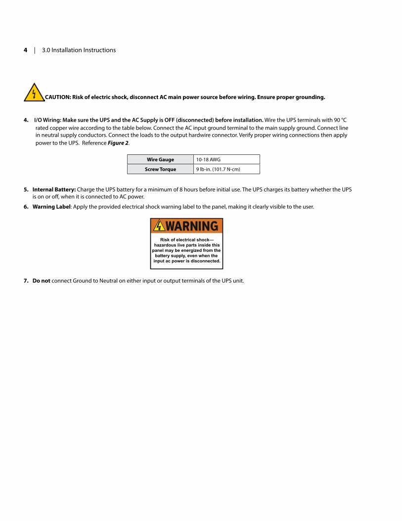
1. POWER ON/OFF/TEST: ON - To turn the UPS ON, press and release the button for more than 2 seconds until you hear “3 quick beeps” and the LEDs light. SELF-TEST - Press the button for less than one second to activate the self-testing. OFF - Press for more than five seconds to turn OFF LED , UPS turn on.
2. Battery Warning/Overload Indicator (Red LED): The LED flashes when the battery needs to be recharged and tested. The LED will illuminate when the unit is subjected to an overload condition. If the unit shuts down due to overload, the LED and alarm will continue for two minutes.
3. ON Battery Indicator (Yellow LED): The LED illuminates when the UPS is supplying battery power to the loads.
4. AC Input Normal Indicator (Green LED): The LED illuminates when the line input voltage is normal.
5. Input: IP20-rated Input Screw Terminals.
6. Output: IP20-rated Output Screw Terminals.
Communication Card Options
SDUCFRELAYCARD
SDUENETIPCARDFigure 4: Front Panel
6 | 5.0 General Description

7. Input Circuit Breaker: Protection from AC overload and short circuit.
8. USB Port: High speed 2.0 Standard USB Type B Peripheral Communication Port used to establish control and monitoring with UPSMON software.
9. COMM PORT: Communication card slot. COMM CARDS: SDUCFRELAYCARD and SDUENETIPCARD NETWORK COMM CARD can be purchased separately.
The UPS can detect the presence of a COMM CARD and identify what kind of COMM CARD is inserted. USB communication will have precedence over COMM CARDS.
10. REMOTE ON/OFF TERMINALS: Use a switch to remotely toggle ON/OFF state. Non-Polarized terminals.
Catalog NumberDimensions in Inches (Millimeters)
H W D
SDU AC - A SERIES 4.87 (123.7) 11.10 (281.9) 4.81 (122.3)
Figure 5: Product Dimensions
SDU AC - A SERIES INSTRUCTION MANUAL | 7

6.0 System Block Diagram
Figure 6: SDU AC - A Series UPS System Block Diagram
8 | 6.0 System Block Diagram

7.0 Operating Instructions7.1 TURNING ON THE UPS
Press the POWER ON/OFF/TEST button for more than 2 second until you hear the “3 quick beeps” and the LEDs turn ON.
Note: If utility power is not present, the UPS will be in back-up mode. The load will be powered from the internal batteries until the discharge point is reached.
7.2 TURNING OFF THE UPS
Hold the POWER ON/OFF/TEST button until the LEDs turn OFF.
7.3 ALARM
Factory default setting is alarm enabled.
To enable/disable Alarm:
When the UPS is in back-up mode, press the POWER ON/OFF/TEST button for at least 1 second to silence the alarm (this function is disabled when the UPS status is either LOW BATTERY or OVERLOAD MODE). To re-enable the alarm, press the POWER ON/OFF/TEST button for at least 1 second. Additionally, you can enable/disable the alarm via UPSMON Software.
7.4 SELF TEST
This UPS has a self diagnostic feature that verifies both the operation of the UPS and the condition of the battery.
In AC mode, press and release the POWER ON/OFF/TEST button for at least 1 second to perform a self-test. During the self-test, the UPS momentarily operates in back-up mode (YELLOW LED will illuminate momentarily then goes back to GREEN). If the UPS passes the self-test, it returns to AC mode.
If the YELLOW LED does not illuminate momentarily, please contact SolaHD Technical Support or your local SolaHD distributor for a replacement.
Additionally a self-test can be ran via UPSMON software.
7.5 GREEN MODE
Factory default setting is Green Mode disabled.
Green Mode is a feature to reserve battery energy in low load conditions. In back-up mode and if the load level is less than approximately 2% ~ 4% (or 60W), the UPS will shutdown to save battery in 180 seconds. If power is restored within 180 seconds, the UPS will return to AC mode.
Green Mode Enable/Disable:
Green Mode can be ENABLED or DISABLED by pressing the POWER ON/OFF/TEST at start-up per TABLE 2:
7.5 Green Mode continued on next page
Green Mode Alarm Signal
Enabled press POWER ON/OFF/TEST button and release until “3 beeps” are heard
Disabled press POWER ON/OFF/TEST button and release until the “2 beeps” are heard
Table 1. Green Mode Setting Table
SDU AC - A SERIES INSTRUCTION MANUAL | 9
7.5 Green Mode continued
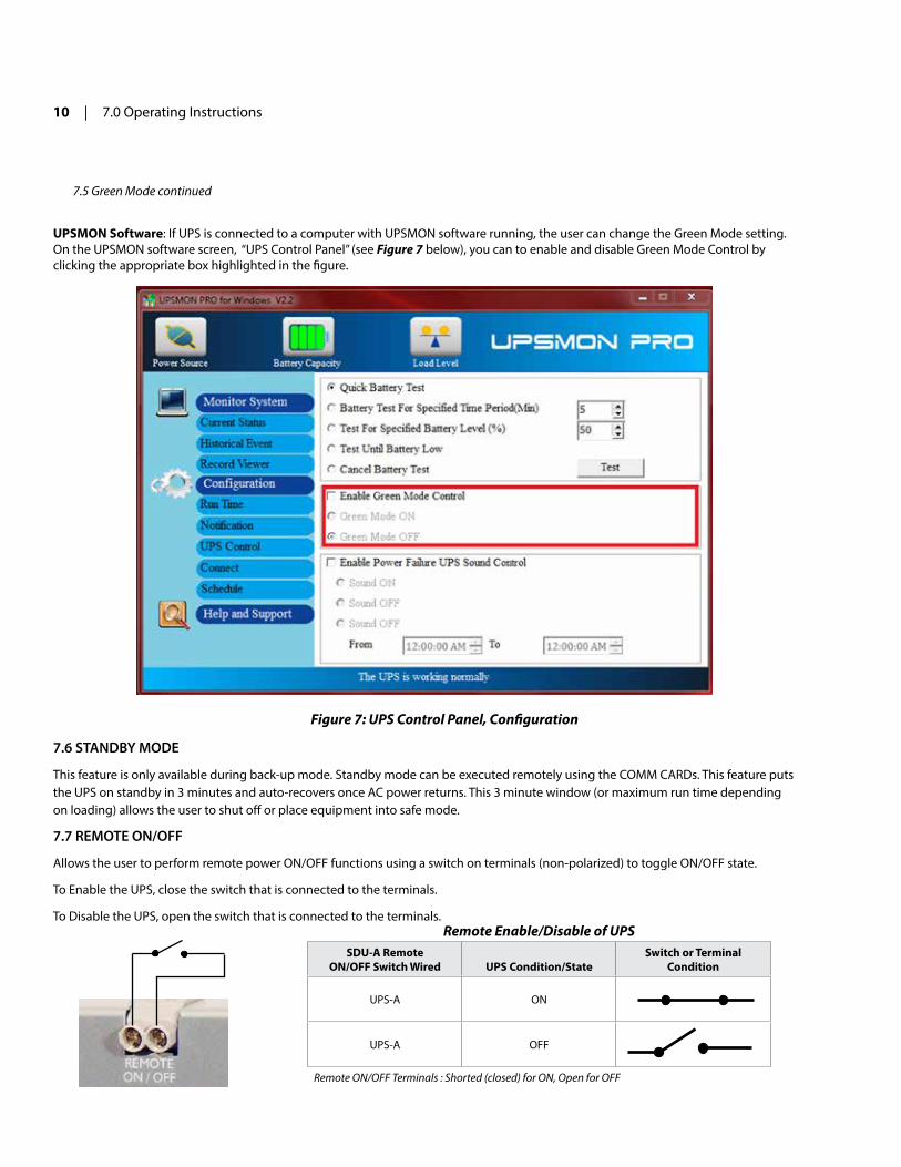
UPSMON Software: If UPS is connected to a computer with UPSMON software running, the user can change the Green Mode setting. On the UPSMON software screen, “UPS Control Panel” (see Figure 7 below), you can to enable and disable Green Mode Control by clicking the appropriate box highlighted in the figure.
7.6 STANDBY MODE
This feature is only available during back-up mode. Standby mode can be executed remotely using the COMM CARDs. This feature puts the UPS on standby in 3 minutes and auto-recovers once AC power returns. This 3 minute window (or maximum run time depending on loading) allows the user to shut off or place equipment into safe mode.
7.7 REMOTE ON/OFF
Allows the user to perform remote power ON/OFF functions using a switch on terminals (non-polarized) to toggle ON/OFF state.
To Enable the UPS, close the switch that is connected to the terminals.
To Disable the UPS, open the switch that is connected to the terminals.
Figure 7: UPS Control Panel, Configuration
SDU-A RemoteON/OFF Switch Wired UPS Condition/State
Switch or Terminal Condition
UPS-A ON
UPS-A OFF
Remote ON/OFF Terminals : Shorted (closed) for ON, Open for OFF
Remote Enable/Disable of UPS
10 | 7.0 Operating Instructions

8.0 Diagnostics
Condition Description LED Diagnostics Alarm
BACK-UP MODE UPS in on back-up mode due to AC Loss YELLOW Slow beeping. UPS sounds until AC utility
power recovers.
AC MODE Normal condition source supplied by AC Mains GREEN No Alarm
AC MODE OVERLOAD
Load around 110% of it's rated capacity GREEN/RED
Alarm is ON for 4 seconds / OFF for 0.8 seconds, until load is removed. UPS will not shut down.
Load > 120% of it's rated capacity GREEN/RED
After continuous alarm for 30 seconds, the UPS will be on standby mode. Next, the alarm will sound for 2 minutes, and the UPS will shut down.
BACK-UP MODE OVERLOAD
Load around 105% of it's rated capacity YELLOW/RED
After continuous alarm for 3 seconds, the UPS will be on standby mode. Next, the alarm will sound for 2 minutes, and the UPS will shut down.
Load > 120% of it's rated capacity YELLOW/RED
After continuous alarm for 3 seconds, the UPS will be on standby mode. Next, the alarm will sound for 2 minutes, and the UPS will shut down.
LOW BATTERY YELLOW
During back-up mode when the battery charge runs low, the UPS beeps rapidly (ON 0.25 seconds, OFF 0.25 seconds) until the UPS shuts down or returns to AC Mode.
GREEN MODE ENABLED
If load < 60W or approximately 2% ~ 4% of the Wattage capacity of the UPS Unit will shutdown
Flashing GREEN LED, every 5 seconds
Alarm sounds every 30 seconds after UPS enters idle mode.
Table 2: Diagnostics LED/Alarms
SDU AC - A SERIES INSTRUCTION MANUAL | 11

9.0 Battery Back-Up TimeThe UPS has an internal 12V sealed Valve Regulated Lead Acid (VRLA) rechargeable battery.
Models SDU 500A, SDU 500A-5 SDU 850A, SDU 850A-5
VA/Watts 500/300 850/510
Battery YUASA NPW36-12 YUASA NPW45-12
Load Level Approximate Back-Up Time (Minutes) Back-Up Time (Minutes)
10% 120 78
20% 51 34
30% 29.5 17
40% 19.5 11
50% 16 9
60% 11 6.5
70% 8 5
80% 6.5 3.5
90% 5 2.5
100% 4 2
Table 3. Battery Back-Up Time Chart
Do not attempt to open the UPS or replace the battery.
Call SolaHD Technical Support for further instructions.
Do not mount the UPS in upside down orientation.
12 | 9.0 Battery Back-Up Time

10.0 Software and InterfacePower Monitoring Software (UPSMON SOFTWARE)
The CD that comes with the UPS contains the UPSMON monitoring/diagnostic software. Install the UPSMON software on your computer. Connect the UPS to your computer via the 2.0 Standard Type A-B USB cable provided.
With the UPSMON software, users can perform monitoring functions and an orderly shutdown of protected equipment in the event of power failure. UPSMON displays diagnostic information such as: voltage, frequency and battery levels. It also allows configuration of the UPS features. Additional details available by selecting the “Help and Support” button of the control panel, as shown in Figure 9.
Figure 8: Connecting UPS to Computer
Figure 9: UPSMON Control Panel, Monitor System
SDU AC - A SERIES INSTRUCTION MANUAL | 13

11.0 StorageAmbient temperature range is -15 °C to +45 °C (5 °F to 113 °F). It is recommended to charge the UPS for at least 8 hours then store the UPS covered and upright in a cool, dry location. Remove accessories and disconnect cables connected to the UPS to avoid unnecessary draining of the battery.
Extended Storage
During extended storage in environments where the ambient temperature is: -15 °C to +30 °C (+5 °F to +86 °F), charge the UPS battery every six months.
During extended storage in environments where the ambient temperature is: +30 °C to +45 °C (+86 °F to +113 °F), charge the UPS battery every three months.
While every precaution has been taken to ensure accuracy and completeness in this manual, Appleton Grp LLC d/b/a Appleton Group assumes no responsibility, and disclaims all liability for damages resulting from use of this information or for any errors or omissions. The SolaHD and Emerson logos are registered in the U.S. Patent and Trademark Office. All other product or service names are the property of their registered owners.©2017 Appleton Grp LLC d/b/a Appleton Group. All rights reserved. Specifications are subject to change without notice.
Aunque se han tomado todas las precauciones para asegurar la exactitud y acuciosidad de este manual, SolaHD no asume responsabilidad alguna, y rechaza toda responsabilidad por daños que pudieran resultar debido al uso de esta información o por cualquier error u omisión. El nombre y el logotipo de ®SolaHD son marcas registradas de Appleton Grp LLC d/b/a Appleton Group. Todos los nombre mencionados son marcas comerciales o registradas de sus respectivos titulares. ©2017 SolaHD. Todos los derechos reservados en el mundo entero. Las especificaciones pueden cambiar sin previo aviso.
Bien que toutes les précautions aient été prises afin d’assurer que les renseignements du présent manuel sont complets et exacts, Sola/Hevi-Duty n’assume aucune responsabilité, et décline toute responsabilité pour des dommages découlant de l’utilisation de cette information ou de toute erreur ou omission. Le nom et le logo ®SolaHD sont des marques déposées de Appleton Grp LLC d/b/a Appleton Group. Tous les noms évoqués sont des marques de commerce ou des marques déposées de leurs propriétaires respectifs.
©2017 SolaHD Tous droits réservés mondialement. Les caractéristiques techniques sont sujettes à modification sans préavis.
14 | 11.0 Storage

SDU AC - A SerieS inStrUCtion MAnUAl

P/N: A272-290 Rev. 4 05/2017
SolaHD is our premium line of power-conversion and power quality solutions products under Appleton Group, a business unit of Emerson.
Emerson brings integrated manufacturing solutions to diverse industries worldwide. Our comprehensive product line, extensive experience, world-class engineering and global presence enable us to implement solutions that give our customers the competitive edge.
For over 150 years, our electrical product brands have been providing a rich tradition of long-term, practical, high quality solutions with applications ranging from the construction and safe operation of petrochemical and process plants to providing quality power that precisely controls automotive robotic production.
Engineers, distributors, contractors, electricians and site maintenance professionals around the world trust Emerson brands to make electrical installations safer, more productive and more reliable.
Appleton Group is organized into three focused businesses that provide distributors and end-users expert knowledge and excellent service.
Electrical Construction Materials This group is made up of the Appleton and O-Z/Gedney brands. They manufacture a broad range of electrical products including conduit and cable fittings, plugs and receptacles, enclosures and controls, conduit bodies and industrial and hazardous lighting. Whether the application is hazardous location, industrial or commercial, the electrical construction materials group has the products to meet your needs.
Power Quality Solutions The SolaHD brand offers the broadest power quality line, including uninterruptible power supplies, power conditioners, voltage regulators, shielded transformers, surge protection devices and power supplies.
Heating Cable Systems This group is made up of the EasyHeat and Nelson brands. They offer a broad range of electrical heating cable products for residential, commercial and industrial applications.
Asia/Pacific+ 65.6556.1100
Australia+ 61.3.9721.0348
Canada+ 1.888.765.2226
China+ 86.21.3338.7000
Europe+ 33.3.22.54.13.90
Mexico/Latin America+ 52.55.5809.5049
Middle East/Africa/India+ 971.4.811.8100
United States+ 1.800.621.1506
Appleton Grp LLC9377 W. Higgins RoadRosemont, IL 600181.800.377.4384solahd.com
While every precaution has been taken to ensure the accuracy and completeness of this literature, SolaHD Corporation assumes no responsibility and disclaims all liability for damages resulting from use of this information or for any errors or omissions. © 2017 SolaHD Corporation. All rights reserved throughout the world. Specifications subject to change without notice. ® SolaHD is a registered trademark of SolaHD Corporation. All names referred to are trademarks or registered trademarks of their respective owners.Appleton Grp LLC d/b/a Appleton Group. The Appleton, O-Z/Gedney, SolaHD, EasyHeat, Nelson and Emerson logos are registered in the U.S. Patent and Trademark Office. EasyHeat, Inc. is a wholly owned subsidiary of Appleton Grp LLC. All other product or service names are the property of their registered owners. © 2017, Appleton Grp LLC. All rights reserved.