Embed Size (px)
Citation preview

ISUNIK2E230v2_GB_10_12.doc
TECHNICAL INSTALLATION MANUAL
FOR AUTOMATIC GATES
WARNING!
Before installing, thoroughly read this manual that is an integral part of this Kit. Prastel S.p.A. declines any responsibility in the event current standards in the country of installation are not complied wit h
The symbol CE conforms with European Directive R&TTE 99/05CE
ELECTRONIC CONTROL PANEL FOR TWO 230VAC MOTORS
UNIK2E230 _ V2 (COMPLETE) UNIK2E230SK _ V2 (WITHOUT BOX AND TRANSFORMER)
BOX IP 54

UNIK2E230 V2 ENGLISH ISUNIK2E230v2_GB_10_12.doc
2
1. INTRODUCTION .......................................................................................... 3
2. MAIN FEATURES ..................................... ................................................... 3
3. TECHNICAL SPECIFICATIONS .......................... ........................................ 3
4. CONNECTION AND SET UP OF THE CONTROL UNIT ......... .................... 4
4.1 GENERAL DIAGRAM OF SETTINGS AND CONNECTIONS ....... ........................... 5 4.2 SIMPLIFIED LEARNING PROCEDURE (also see pages 8-10) .............................. 6 4.3 PROFESSIONAL LEARNING PROCEDURE (see also pages 8-1 0) ...................... 7
5. CONTROL UNIT OPERATING LOGIC (ANALYTIC EXAM) ...... .................. 8
5.1 PROGRAMMING AND CANCELLATION OF THE REMOTE CONTROLS ............. 8 5.2 OPERATION OF THE SAFETY DEVICES ................... ............................................ 8 5.3 TRIMMER “FOR”- MOTOR SPEED ........................ ................................................. 9 5.4 TRIMMER “DEL”- DELAY BETWEEN MOTORS ............... ..................................... 9 5.5 TRIMMER “PAU” - “OPENING AND CLOSING” OPERATING MOD E .................. 9 5.6 “PEDESTRIAN OPENING” FUNCTION ..................... ............................................ 11 5.7 TRIMMER “OBS” - “OBSTACLE SENSITIVITY” DETECTION .. ........................... 11 5.8 FLASHING LIGHT .................................... .............................................................. 11 5.9 GATE OPEN WARNING LIGHT ........................... .................................................. 11 5.10 SLOW-DOWN ......................................................................................................... 11 5.11 ELECTRIC LOCK ..................................... .............................................................. 12 5.12 COURTESY LIGHT ................................................................................................. 12 5.13 LOGICAL STOP (STP INPUT) .......................... ...................................................... 12 5.14 CONTROL UNIT MEMORY FAULT ......................... ............................................... 12
6. SIGNALLING LED .................................... ................................................. 12
7. PROGRAMMING THROUGH GTSYSTEM ................................................ 13
8. ACCESSORIES ABSORPTION CHECK INFORMATION .......... ............... 13
9. TROUBLESHOOTING ................................... ............................................ 14
SAFETY WARNINGS FOR INSTALLATION AND USE .......... ......................................... 15

UNIK2E230 V2 ENGLISH ISUNIK2E230v2_GB_10_12.doc
3
1. INTRODUCTION
UNIK2E230 is a universal self-learning control unit especially designed for the automatic control of 230VAC powered, 1 or 2 motor driven accesses. It is fitted with an innovative self-learning proce dure allowing rapid installation and four trimmers for fine adjustment of the main parameters; force, pause time, obstacle detection sensitivity and out of phase closing whe n two motors are used. The following are available: - simplified programming , thanks to which the unit automatically performs a learning operation to acquire running time and determine slow-down setting at 85% of opening and closing runs; - A professional programming in which the installer can determine the instant in which the gate starts to slow-down , the enabling of the pedestrian opening via radio , the safety device trigger mode.
2. MAIN FEATURES
• Management and control of 230VAC (max 400W) powered, 1 or 2 motor-driven automated accesses
• Motors closing offset adjustable from 0 to 15 seconds using trimmers
• Opening motors delay settable at 0 or 3 seconds
• Double limit switch input open close
• Motor force (speed) adjustable from 50-100%.using a trimmer.
• Customisable partial opening (for pedestrian transit)
• 0 to 60” stand-by time adjustment via trimmer.
• 0.1 to 3.0” obstacle detection triggering time adjustment via trimmer.
• Initial settings using dip-switches
• Signalling LEDs (8)
• Expansion for electric lock 12V 15W max (optional board ELU, with optional relay)
• Expansion for courtesy light (optional board LCU)
• Built-in 433MHz rolling-code receiver with 180 memorisable codes
• Built-in flashing logic management
• Flash microprocessor re-programmable on-board via serial interface.
• Programming and control of the control unit using a portable terminal GTSYSTEM (optional)
• Built to European reference Directive Standards (R&TTE 99/05/CE) DECLARATION OF CONFORMITY Prastel S.p.A. declares that UNIK2E230 IS IN ACCORDANCE with the 99/05/EC (R&TTE) direcitve The complete declaration of conformity is available in Prastel or to the internet address www.prastel.it
3. TECHNICAL SPECIFICATIONS
Transformer power supply: primary230 / secondary 18V 20VA / secondary12V 20VA
Control unit power: 230VAC
Motor output: 2 x 400W
Max current peak of motor: Max 8 Ampere
Accessories power: 24 VDC - 500 mA protected by fuse (see info page 13)
Environmental operating temperature : -20°C / + 55 °C
Programming parameters: memorised in EEPROM
Functions handler: microprocessor with watch-dog
BOX IP rating: IP54

UNIK2E230 V2 ENGLISH ISUNIK2E230v2_GB_10_12.doc
4
4. CONNECTION AND SET UP OF THE CONTROL UNIT
a) Before installing the UNIK2E230 control unit, read the “General safety warnings and notes” (page 15).
b) Mount a differential thermo-magnetic circuit breaker 6A (IC=30mA) on the mains supply as specified in the current reference standards (IC = differential current).
c) * Fix the box using the special fixing holes. d) * Place the supplied cable-ways and insert the cables keeping the power and supply
cables separate from each other. e) Connect the motors to the terminal blocks “MOT1” e “MOT2”; if only one motor is used
connect it to the terminal blocks “MOT1”. f) Connect the external accessories making sure that the total of the average absorption
of all the connected accessories is less than the maximum current available (see info page 13).
g) ATTENTION: Connect the limit switches if present , otherwise do not bridge inputs FC1, FC2, FO1, and FO2 in the terminal board.
h) ATTENTION: To avoid noisy or irregular operating when the control panel is used with hydraulic operators, the following is recommen ded:
• set the Force to 100% (“FOR” trimmer completely clockwise). • do not use the slow-down (carry out the professional learning procedure). • do not use the obstacle detection (trimmer OBS to MAX),
i) During the learning with no electric limit switches present and with the obstacle detection disabled (e.g. with hydraulic operators), or else with no mechanical STOP (strike plate) present, to define the manoeuvre times:
• Press pushbutton 1 of the remote control or pushbutton P1/SET to stop the gate in the desired position.
• Press pushbutton 2 of the remote control or pushbutton P2/SET to stop the gate in the desired position.
j) Check the correct connection and operation of all the accessories connected to the terminal board.
NOTE: * When the control panel is mounted directly onto the operator with the special control
panel-holder, these two points are not relevant.
INITIAL FACTORY SETTINGS If there is no programming , the control unit will operate as follows:
• Step by step mode with automatic closing disabled • No slow-down • Closing safety present • No opening safety • Obstacle detection trigger time (OBS) 1 second • 3 second opening and closing time of the motors • Pushbutton 1 of transmitters enabled • Safety test disabled • Kick-back disabled

UNIK2E230 V2 ENGLISH ISUNIK2E230v2_GB_10_12.doc
5
4.1 GENERAL DIAGRAM OF SETTINGS AND CONNECTIONS
30 31 32 33 34
UNIK2E230 V2 ENGLISH ISUNIK2E230v2_GB_10_12.doc
6
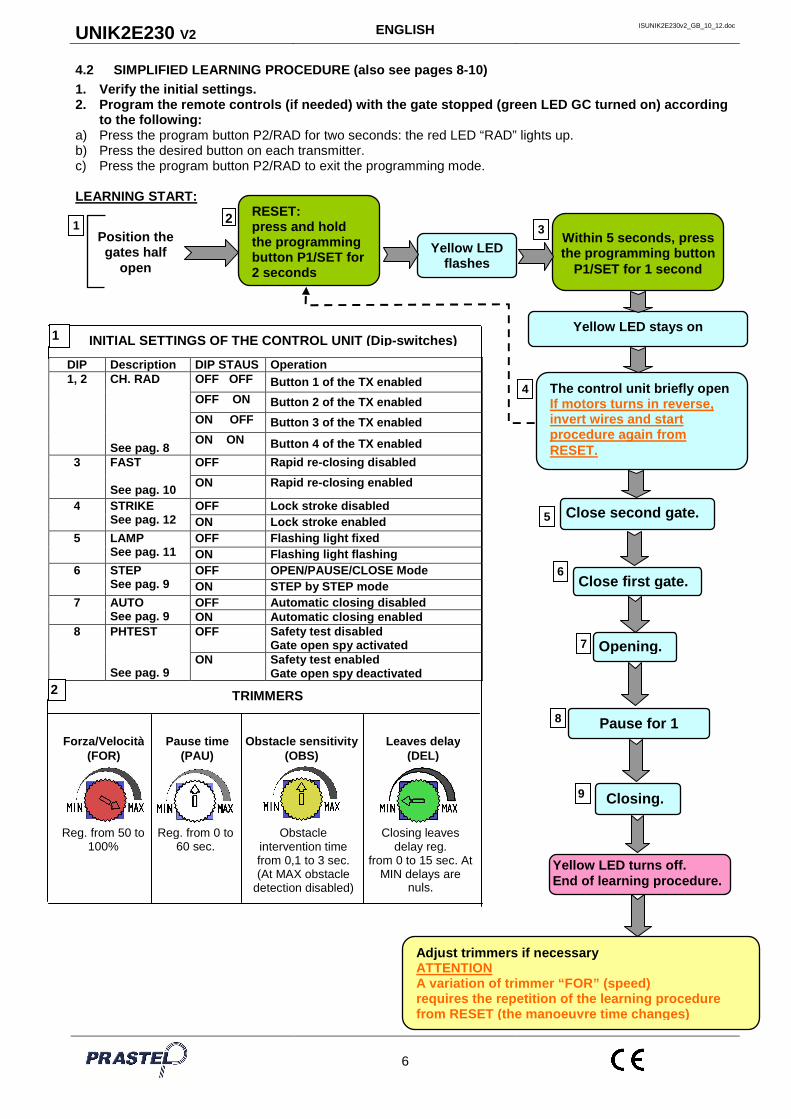
4.2 SIMPLIFIED LEARNING PROCEDURE (also see pages 8 -10) 1. Verify the initial settings. 2. Program the remote controls (if needed) with the gate stopped (green LED GC turned on) according
to the following: a) Press the program button P2/RAD for two seconds: the red LED “RAD” lights up. b) Press the desired button on each transmitter. c) Press the program button P2/RAD to exit the programming mode. LEARNING START:
Position the gates half
open
Yellow LED flashes
Yellow LED stays on
The control unit briefly open If motors turns in reverse, invert wires and start procedure again from RESET.
Within 5 seconds, press the programming button
P1/SET for 1 second
Adjust trimmers if necessary ATTENTION A variation of trimmer “FOR” (speed) requires the repetition of the learning procedure from RESET (the manoeuvre time changes)
Closing.
RESET: press and hold the programming button P1/SET for 2 seconds
1 3
4
5
8
6
7
2
DIP Descrip tion DIP STAUS Operation 1, 2 CH. RAD
See pag. 8
OFF OFF Button 1 of the TX enabled OFF ON Button 2 of the TX enabled ON OFF Button 3 of the TX enabled ON ON Button 4 of the TX enabled
3 FAST See pag. 10
OFF Rapid re -closing dis abled
ON Rapid re -closing enabled
4 STRIKE See pag. 12
OFF Lock stroke disabled ON Lock stroke enabled
5 LAMP See pag. 11
OFF Flashing light fixed ON Flashing light flashing
6 STEP See pag. 9
OFF OPEN/PAUSE/CLOSE Mode ON STEP by STEP mode
7 AUTO See pag. 9
OFF Automatic closing disabled ON Automatic closing enabled
8 PHTEST See pag. 9
OFF Safety test disabled Gate open spy activated
ON Safety test enabled Gate open spy deactivated
INITIAL SETTINGS OF THE CONTROL UNIT (Dip -switches) 1
2
Pause time (PAU)
Obstacle sensitivity (OBS)
Leaves delay (DEL)
TRIMMERS
Reg. from 50 to 100%
Reg. from 0 to 60 sec.
Obstacle intervention time from 0,1 to 3 sec. (At MAX obstacle
detection disabled)
Closing leaves delay reg.
from 0 to 15 sec. At MIN delays are
nuls.
Forza/Velocità (FOR)
Close second gate.
Close first gate.
Opening.
Pause for 1
9
Yellow LED turns off. End of learning procedure.
UNIK2E230 V2 ENGLISH ISUNIK2E230v2_GB_10_12.doc
7
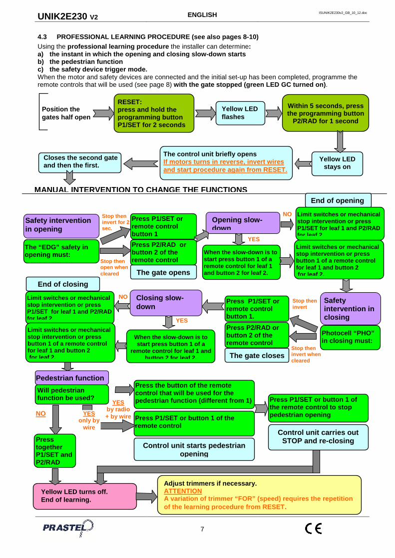
4.3 PROFESSIONAL LEARNING PROCEDURE (see also pages 8-10) Using the professional learning procedure the installer can determine: a) the instant in which the opening and closing slo w-down starts b) the pedestrian function c) the safety device trigger mode. When the motor and safety devices are connected and the initial set-up has been completed, programme the remote controls that will be used (see page 8) with the gate stopped (green LED GC turned on) .
Yellow LED flashes
Yellow LED stays on
The control unit briefly opens If motors turns in reverse, invert wires and start procedure again from RESET.
Closes the second gate and then the first.
RESET: press and hold the programming button P1/SET for 2 seconds
Position the gates half open
Within 5 seconds, press the programming button
P2/RAD for 1 second
Stop then invert
Stop then invert when cleared
Yellow LED turns off. End of learning.
When the slow -down is to start press button 1 of a remote control for leaf 1 and button 2 for leaf 2.
Press P1/SET or remote control button 1.
The gate closes
Will pedestrian function be used?
Press together P1/SET and P2/RAD
Press the button of the remote control that will be used for the pedestrian function (different from 1)
Control unit starts pedestrian opening
Press P1/SET or button 1 of the remote control to stop pedestrian opening
Press P1/SET or button 1 of the remote control
NO YES only by
wire
Photocell “PHO” in closing must:
Press P2/RAD or button 2 of the remote control
Opening slow -down
Pedestrian function
Safety intervention in closing
Safety interven tion in opening
The “EDG” safety in opening must: Stop then
open when cleared
Stop then invert for 2 sec.
Press P1/SET or remote control button 1 Press P2/RAD or button 2 of the remote control
Limit switches or mechanical stop intervention or press button 1 of a remote control for leaf 1 and button 2 for leaf 2.
YES
NO
End of opening
When the slow -down is to start press button 1 of a
remote control for leaf 1 and button 2 for leaf 2.
Closing slow -down
Limit switches or mechanical stop intervention or press P1/SET for leaf 1 and P2/RAD for leaf 2. YES
NO
End of closing
Adjust trimmers if necessary. ATTENTION A variation of trimmer “FOR” (speed) requires the r epetition of the learning procedure from RESET .
MANUAL INTERVENTION TO CHANGE THE FUNCTIONS
YES by radio + by wire
The gate opens
Control unit carries out STOP and re-closing
Limit switches or mechanical stop intervention or press P1/SET for leaf 1 and P2/RAD for leaf 2.
Limit switches or mechanical stop intervention or press button 1 of a remote control for leaf 1 and button 2 for leaf 2.
UNIK2E230 V2 ENGLISH ISUNIK2E230v2_GB_10_12.doc
8
5. CONTROL UNIT OPERATING LOGIC (ANALYTIC EXAM)
5.1 PROGRAMMING AND CANCELLATION OF THE REMOTE CONT ROLS With the receiver built into the control box, Prastel dip-switch, fixed code and rolling code remote controls can be indifferently learned.
5.1.1 Programming Power the control panel and with the automation stopped (green LED GC turned on): • Press the “P2/RAD” pushbutton: the red LED lights up to indicate that the programming is activated. • Make a transmission by pressing one of the pushbutt ons on the transmitter • The code is memorised. During code insertion, the red LED flashes slowly. At the end, the red LED returns
to a fixed light to indicate that a new remote control can be inserted. • Memorise all the transmitters by carrying out a transmission with a chosen channel. • At the end of the operation press the “P2/RAD” pushbutton again to exit the procedure. The red LED
switches off. ATTENTION: The exit from the procedure occurs autom atically 10 seconds after the last transmission.
5.1.2 Total cancellation of the codes
• Press and hold down the “P2/RAD” pushbutton for 3 seconds; the red LED starts flashing quickly. • Press the “P2/RAD” pushbutton again (within 6 seconds) to confirm the cancellation. The confirmation is
signalled when the red LED starts flashing more rapidly.
5.1.3 Enabling new remote “Rolling Code” transmitters (RP A) To enable a new transmitter without intervening on the receiver, a transmitter already enabled for the authorisation must be used (MPSTP2E, MPSTL2E, MPSTL4E, MT2E, MT4E, TRQ2 or TRQ4). • With this authorised transmitter, press and release the RPA learning pushbutton (also see the instructions of
the TX used). • Carry out this operation 5-6 metres from the receiver (the LED signals the activation). • Transmit by pressing one of the channel pushbuttons of the new transmitter to be enabled. • Enable all the new transmitters by pressing a pushbutton on each one of them. • The exit from the procedure occurs automatically 10 seconds after the last transmission. • Check the effective programming of the transmitters by carrying out an opening manoeuvre with each of
them.
5.1.4 Choosing the transmitter pushbutton To select the radio channel that will activate the manoeuvre cycle set DIP 1 and 2 as follows:
DIP- SWITCH 1 DIP- SWITCH 2 Pushbutton Active
OFF OFF Pushbutton 1
OFF ON Pushbutton 2
ON OFF Pushbutton 3
ON ON Pushbutton 4
5.2 OPERATION OF THE SAFETY DEVICES
5.2.1 Photocell (PHO input) When triggered, the photocell provokes: - in closing phase, an inversion of the motion, either immediate or when cleared, according to the programming, - in opening phase it has no effect, - when the access is closed it has no effect on the opening commands if set for immediate inversion, otherwise it delays the opening until it is cleared , - if the access is open it inhibits the closing commands. The control unit has a function of rapid access closing after the triggering of the photocell (see paragraph 5.3.4).
5.2.2 Safety in Opening (EDG input)
Safety devices can be connected (self-testing or not) to the “EDG” input on the control unit (e.g. fixed wire ribs, pneumatically-operated ribs, etc.). The safety acts as follows: - in closing phase it has no effect - in opening phase it provokes an inversion of direction for 2 seconds, - when the gate is closed the opening commands are inhibited,
UNIK2E230 V2 ENGLISH ISUNIK2E230v2_GB_10_12.doc
9
- when the gate is open the closing commands are inhibited, Using the professional learning , the PED input can be set as internal photocell: - in closing phase it provokes an inversion of direction when cleared, - in opening phase it provokes a STOP and opening continues when cleared, - when the gate is closed it delays opening until it is cleared, - when the access is open it inhibits the closing commands.
5.2.3 Safeties Self-test The control unit has a self-test function of the safeties connected to the “PHO” input of the control unit; it switches off the transmitter to check the commutation of the corresponding receiver contact before the execution of each manoeuvre. In this case, the “gate open warning light” is not available. To activate this self-test function proceed as follows: - switch DIP 8 “PTST” to ON - connect the positive of the photocell transmitter power to terminal 10 (“+TX”) With the Self-test function active the photocell transmitters are only powered when the ma noeuvre is taking place, thus giving a major saving of energy. If the enabling of the safety self-test is not required - switch DIP 8 “PTST” to OFF - connect the positive of the photocell transmitter power to the terminal 11 (“+V”)
5.3 TRIMMER “FOR”- MOTOR SPEED Trimmer “FOR” adjusts the voltage applied to the motors during operations, which means adjusting the speed of the motors. With the trimmer turned fully counter-clockwise the speed of the motor if 50% of the maximum speed. With the trimmer at half travel the speed of the motor if 75% of the maximum speed. ATTENTION: Changing the setting of trimmer “FOR” re quires repeating the learning procedure, since the travel times and the slow-down start times chan ge.
EXAMPLE
Force/Speed 50%
EXAMPLE
Force/Speed 75%
EXAMPLE
Force/Speed 100%
5.4 TRIMMER “DEL”- DELAY BETWEEN MOTORS Trimmer “DEL” can be used to adjust the delay between the two motors in opening and closing operations. If the trimmer is turned fully counter-clockwise, the delay is 0 both in opening and in closing, and the two leaved will move together. In all the other positions of the trimmer, the delay in opening is 3 seconds and the delay in closing varies from 0 to 15 seconds according to the position of the knob.
EXAMPLE
delay 0 in opening delay 0 in closing
EXAMPLE
delay 3 seconds in opening delay 7 seconds in closing
EXAMPLE
delay 3 seconds in opening delay 15 seconds in closing
5.5 TRIMMER “PAU” - “OPENING AND CLOSING” OPERATING MODE
5.5.1 Time controlled automatic closing mode Switch the dip-switch 7 to OFF and the dip-switch 8 to ON. Set the “PAU” trimmer in an intermediate position according to the pause time desired. The pause time can be set between 3 and 60 seconds and is increased by rotating the trimmer clockwise.
EXAMPLE
pause time about 1 sec.
EXAMPLE
pause time about 30 sec.
EXAMPLE
pause time about 60 sec.
In this mode, if a command is received via radio or via the “STR” input, the control unit does the following: - carries out a fixed one second pre-flash
UNIK2E230 V2 ENGLISH ISUNIK2E230v2_GB_10_12.doc
10
drives the two motors without 2nd motor delay if the DEL trimmer is turned fully counter-clockwise, with a 2nd motor delay of 3 seconds for all the other positions of the DEL trimmer. - activates the operator for one second at maximum speed and then at the speed set with the “FOR” trimmer. - the opening terminates when the limit switch or the obstacle detection device are triggered or the manoeuvre time has elapsed. If other commands are given during opening, they will have no effect. - with the automation stopped and in automatic standby each time the timer restarts from zero. When the standby time has elapsed, the closing manoeuvre occurs and the control unit: - carries out a fixed one second pre-flash - drives the two motors with a 2nd motor delay as set on the DEL trimmer - if other commands are issued during closure, the control unit carries out a complete re-opening. - the closure terminates when the limit switch or the obstacle detection device are triggered or the manoeuvre time has elapsed. ATTENTION: Maintaining the opening contact (“STR” t erminal) closed, with a temporised relay for example, the control unit will command opening and the automation will remain open with automatic closing disabled until the contact is re-opened aga in (Company Function).
5.5.2 Step by step mode without automatic closing Switch the dip-switch 6 to ON and the dip-switch 7 to OFF. The step by step command sequence is OPEN-STOP-CLOSE-STOP The opening and closing manoeuvres take place as described in the previous paragraph.
5.5.3 Step by step mode with automatic closing Switch the dip-switch 6 to ON and the dip-switch 7 to ON. The step-step logic is OPEN/STOP/CLOSE/STOP. When the opening manoeuvre has been completed and the pause time set on the PAU trimmer has elapsed the control unit effects automatic closing. If, when the automation is closed, a radio command is given, either through the “STR” input command or the START pushbutton on the board, the control unit: - commands a one second fixed pre-flash drives the two motors without 2nd motor delay if the DEL trimmer is turned fully counter-clockwise, with a 2nd motor delay of 3 seconds for all the other positions of the DEL trimmer.- the opening terminates when the limit switch or the obstacle detection device are triggered, the manoeuvre time has elapsed or there is a radio or manual command. In the latter case, the control unit disables the automatic closing and to restart the manoeuvre, a further command is required. If the automation is completely open, once the standby time has elapsed the closing manoeuvre occurs and the control unit: - carries out a fixed one second pre-flash. - drives the two motors with a 2nd motor delay as set on the DEL trimmer - the closing terminates when the limit switch or the obstacle detection device are triggered or the manoeuvre time has elapsed.
5.5.4 Automatic closing and rapid re-closing mode Switch the dip-switch 6 to OFF and the dip-switch 7 to ON. Switch the dip-switch 3 to ON. The control unit does the following: a) if the photocell is triggered during opening, the control unit continues the opening, and when the photocell is cleared effects a STOP followed, after one second, by the re-closure. b) if the photocell is triggered during standby with the gate open, when the photocell is cleared, after one second, automatic re-closure occurs. c) if the photocell is triggered during closure, the control unit effects an inversion and, when the photocell is cleared, it effects a STOP followed, after one second, by the re-closure. If, during the opening cycle or during standby, the photocell is not triggered, the pause time is that which is set with the “PAU” trimmer.
5.5.5 OPEN-CLOSE-OPEN mode Switch the dip-switch 6 to OFF and the dip-switch 7 to OFF. If, when the automation is closed, a radio command is given, either through the “STR” input command or the START pushbutton on the board, the control unit: - commands a one second fixed pre-flash - drives the two motors without 2nd motor delay if the DEL trimmer is turned fully counter-clockwise, with a 2nd motor delay of 3 seconds for all the other positions of the DEL trimmer. - the opening terminates when the limit switch or the obstacle detection device are triggered or the manoeuvre time has elapsed. If other commands are given during opening, they will not have any effect.
UNIK2E230 V2 ENGLISH ISUNIK2E230v2_GB_10_12.doc
11
When the automation is completely open, to start the closing manoeuvre give a radio or manual command and the control unit: - carries out a fixed one second pre-flash - drives the two motors with a 2nd motor delay as set on the DEL trimmer - if a command is issued during closure, the control unit carries out a complete re-opening. - the closure terminates when the limit switch or the obstacle detection device are triggered or the manoeuvre time has elapsed.
5.6 “PEDESTRIAN OPENING” FUNCTION The pedestrian function can be assigned with the professional learning to channel 2/3/4 of the remote control. With a “PEDESTRIAN OPENING” (“EDG” terminal) command on the input, the control unit commands an opening for the first leaf for a time of: - 5 seconds if no learning has been carried out, - half of the course if a simplified learning has been carried out - that set by the installer if a professional learning has been carried out. Closing is triggered by a manual command, or automatically if the automatic closing function is enabled. The complete opening command has always priority over the pedestrian opening, therefore if, during a pedestrian manoeuvre a complete opening command is received, the control unit will command a complete opening of the automation.
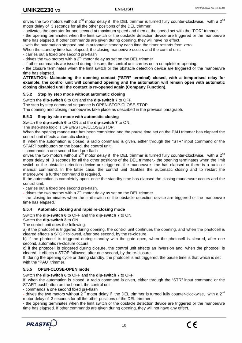
5.7 TRIMMER “OBS” - “OBSTACLE SENSITIVITY” DETECTIO N The “OBS” TRIMMER is used to adjust at the same time the delay time of intervention after an obstacle has been detected and the threshold of the counter-force against the operator necessary to trigger the intervention. Both the counter-force and the delay time increase when the trimmer is turned clockwise. The delay time can be adjusted between 0.1 and 3 seconds. This function is useful to overcome any critical points of the operator which cause a higher power absorption by the motor for a short time.
EXAMPLE
delay time about 0,1 sec.
EXAMPLE
delay time about 1,5 sec.
EXAMPLE
delay time about 3 sec.
If the OBS trimmer is in the MAX position, the obst acle detection is disabled. If electric limit switches are present, the obstacle detector will provoke an inversion of the motion in closing and a 2 second inversion in opening. If there are no electric limit switches the obstacl e detector provokes: - in closing an inversion of the motion unless it is in the last five seconds of the manoeuvre, where does a STOP - in opening an inversion of the motion for 2 seconds unless it is in the last five seconds of the manoeuvre, where does a STOP.
5.8 FLASHING LIGHT The control unit has two output terminals (LAMP) to command a low voltage flashing light. The light start flashing 1 second before each opening manoeuvre and 1 second before each closing manoeuvre. If the dip-switch 5 is in the OFF position the power supply to the flashing light is continuous. Therefore the terminals must be connected to a low voltage flashing light with a built-in oscillating circuit (type FEBOLIF). If the dip-switch 5 is in the ON position the power supply is intermittent and therefore a normal lamp without oscillating circuit can be connected (230VDC, Max 10W). During the closing manoeuvre, the flashing frequency is twice as fast as that during opening. The flashing light is only activated during movemen t.
5.9 GATE OPEN WARNING LIGHT If the safety device self-test is not used (DIP 8 “PTST” is OFF), the output +TX (terminal 10) acts as a GATE OPEN WARNING LIGHT. You can connect a 24V lamp (max. 3W) to terminals 10 (“+TX”) and 9 (“COMMON”) of the control unit. The status of the lamp is as follows: - If the access is closed the light is switched off - If the access is open or opening the lamp is alight with a fixed light - If the access is closing the lamp flashes
5.10 SLOW-DOWN The slow-down function allows the gate to apply a reduced force before reaching the limit stop. The speed is reduced to about one third of the normal working speed. The slow-down function can be enabled or not during the Professional Learning procedure. The moment in which the slow-down starts can be differentiated between the opening and the closure.

UNIK2E230 V2 ENGLISH ISUNIK2E230v2_GB_10_12.doc
12
5.11 ELECTRIC LOCK There is an output (EL) for the electric lock 12V max 15VA . The command is given before every opening manoeuvre for 2 seconds, and before every re-opening caused by the triggering of a photocell or safety device. Using dip-switch 4 on the card, the kick-back and the final stroke at the end of the closing manoeuvre can be enabled or not. Dip-switch 4 in ON position: kick-back and final stroke enabled Dip-switch 4 in OFF position: kick-back and final stroke disabled.
5.12 COURTESY LIGHT Using the LCU expansion card a courtesy light can be managed. The contact given by the LCU card is clean and allows a 230VAC max.500W lamp to be managed. The command to switch on the courtesy light is given before every manoeuvre and the contact remains activated for about 120 seconds from opening.
5.13 LOGICAL STOP (STP INPUT) The activation of the STOP input stops all the func tions. To resume the cycle the STOP must be deactivated and another command given.
5.14 CONTROL UNIT MEMORY FAULT The EEPROM memory contains the control unit operating parameters, the codes, the logic and the memory of the radio receiver. When the control unit is turned on, should there be a fault in the EEPROM memory, the red LED flashes and all manoeuvres are blocked. The Reset function must be executed (press and hold the programming button P1/SET for 2 seconds, until the yellow LED flashes). If the red LED turns of, the EEPROM is good, but all programming of parameters and learning of transmitters must be done again. If the red LED still flashes, an authorised service centre should be contacted.
6. SIGNALLING LED
Yellow led SET: - flashes for 5 seconds when turned on to indicate that it is possible to enter the Professional or Simplified
Learning modes. - lights up with a fixed light while Professional or Simplified Learning are carried out. - is turned off when the control unit functions normally. Red led ER: - is turned off during normal control unit operations - is alight (fixed light) when the control unit is blocked because it has failed the safety test or there is a TRIAC in short circuit or a motor is disconnected Red led RAD: - flashes briefly when a 433 MHz Multipass radio code is received - is alight (fixed light) when radio codes are being memorised - flashes rapidly when the control unit is switched on and the radio code memory is defective - flashes rapidly during the cancellation of radio codes - flashes slowly when there is an attempt to memorise new radio codes and the memory is full - is switched off when the control unit is functioning normally and waiting to receive a command via radio. Green led GC: - is alight (fixed light) when the automation is completely closed - flashes during the closing manoeuvre - otherwise it is switched off Red led GO: - is alight (fixed light) when the automation is open. - flashes during the opening manoeuvre - otherwise it is switched off Red led PH: - is alight when the photocell (PHO input) is aligned - is switched off when the photocell (PHO input) is not aligned Red led ST: - is alight when the STOP (STP) input is closed - is switched off when the STOP (STP) input is open. Green led START: - is alight when the OPEN/STEP/STEP (STR) input is closed . - is switched off when the OPEN/STEP/STEP (STR) input is open .
UNIK2E230 V2 ENGLISH ISUNIK2E230v2_GB_10_12.doc
13
7. PROGRAMMING THROUGH GTSYSTEM
The GTSYSTEM is an autonomous multi-functional terminal that can be used on various Prastel products both for testing and function modification. In the case of UNIK2E230 control unit, it allows: • modification or visualisation of operating parameters, • visualisation of the counter of completed manoeuvres, • visualisation of the control unit status and diagnostic messages. 8. ACCESSORIES ABSORPTION CHECK INFORMATION
(Transformer dimensioning)
The current available for the accessories is given by the power available for the accessories divided by the voltage of the accessories 24VDC.
Iacc = Pacc / 24
The power available for the accessories is given by the transformer power, less the power absorbed by the control unit (8W). Pacc = Ptras – 8 On board the control unit, there is a 20VA transformer for which the available power is 12W and the available current is 500mA as described in the technical characteristics. Below un example of calculation of the current available for the accessories.
Control Unit Transformer
Power
Power absorbed by the control
unit
Power available for the
accessories
Voltage of the accessories
Current available for the
accessories
UNIK2E230 20VA 6.4W 13.6W 24V 560mA The following table shows the average absorption of the most common Prastel/VDS accessories:
Product Absorption Photocell FOTO30SDE (couple TX+RX) 50 mA Photocell FOTO35SDE (couple TX+RX) 50 mA Induction detector MLX24AZ 40 mA Receiver MR1E 20 mA Microwave detector DM30 80 mA Microwave detector DM60 100 mA Amplifier for infra-red barrier FOTOTEST2D 30 mA Pneumatic edge receiver TCO4RX 30 mA Standalone keypad EASYBKA 100 mA Standalone proximity reader EASYMINI 30 mA
Example : connecting 2 pairs of FOTO30SDE photocell and a MLX24AZ detector the overall average absorption is 140mA. Should it be necessary to connect accessories with an overall average absorption that is more than that available, the transformer must be replaced with a more powerf ul one. Use transformers with a secondary of 18 or 20VAC.
Ptras = transformer power Pmot = motor power
Iacc = current available for accessories Pacc = power available for accessories

UNIK2E230 V2 ENGLISH ISUNIK2E230v2_GB_10_12.doc
14
9. TROUBLESHOOTING
PROBLEM PROBABLE CAUSE REMEDY
On giving a command with the remote control or with the key-switch, the gate does not open .
230 volt mains voltage absent Check master switch
Emergency STOP present Check for any STOP commands connected to the STP input.
There is no jumper between the STP input and the common.
If not used, check if there is a jumper on the STP input.
One of the fuses is burnt out. Replace the fuse with one of the same value.
Motor power cable not connected or faulty.
Check the connection of the cable in the terminal board or replace it.
The gate opens but does not close.
The photocell, if present, is obstructed or not functioning.
Check, clean the photocell or remove the obstacle.
The photocell is missing and there is no jumper between the PHO input and the common.
Check the accessory connections and the presence of the “jumper”.
A key selector NC contact has been used instead of an NO contact to connect to the STR input
Check the connections.
The operator functions by wire but not with the remote control.
The remote control has not been memorised or is broken or the battery is flat.
Check/change the battery.
Carry out the remote control acknowledgement procedure.
The electrical limit switch activates but the motor does not stop.
The opening and closing limit switches have been exchanged. An NO contact has been used instead of an NC.
Check the connections.
The gate moves then stops, both in opening and closing.
The motor force is insufficient and/or the trigger threshold of the OBS is too low.
Check if the leaves are in axis, lubricate if necessary.
Increase the trigger threshold by turning the OBS trimmer clockwise.
If it is not sufficient, increase the FOR trimmer clockwise and reprogram from RESET
When commanded, the motor starts but the gate does not move.
There is an obstacle in front of the gate; the hinges are blocked; a motor fixing bracket has detached.
Remove any obstacles from the gate; restore the hinges, replace or lubricate them.
Fix the motor fixing bracket.
N.B.: If the problem persists, contact your Retaile r or the nearest Service Centre. ATTENTION: Before sending a remote control to be re paired, check that the batteries are not flat. 50% of all remote controls that return for servicin g only have flat batteries.

15
SAFETY WARNINGS FOR INSTALLATION AND USE These warnings are an essential, integral part of the product and must be given to the user. They provide important indications on the installation, use and maintenance and must be read carefully. This form must be preserved and passed on to subsequent users of the system. The incorrect installation or improper use of the product may be dangerous. INSTALLATION INSTRUCTIONS • The installation must be performed by professionally skilled personnel and in compliance with current
local, state, national and European legislation. • Before beginning the installation, check the integrity of the product. • The laying of cables, electrical connections and adjustments must be workmanlike performed. • The packing materials (cardboard, plastic, polystyrene, etc.) are a potential hazard and should be
disposed of correctly and not left within reach of children. • Do not install the product in potentially explosive environments or environments disturbed by
electromagnetic fields. The presence of inflammable gases or fumes is a grave danger to safety. • Set up a safety device for overvoltage, a disconnecting and/or differential switch suitable for the product
and conforming to current standards. • The manufacturer declines any and all responsibility for product integrity, safety and operation in the
event incompatible devices and/or components are installed. • Solely original spare parts should be used for repairs and replacements. • The installer must provide all the information relative to the operating, maintenance and use of the
individual components and the complete system as specified in the MACHINE LEGISLATION (see regulations EN 12635, EN 12453 and EN 12445).
MAINTENANCE • To ensure product efficiency, it is essential that professionally skilled personnel carry out maintenance
within the times established by the installer, the manufacturer and by current legislation. • All installation, maintenance, repairs and cleaning operations must be documented. This documentation
must be preserved by the user, and made available to the personnel responsible for the control. WARNINGS FOR THE USER • Read the instructions and enclosed documentation carefully. • The product must be used for the express purpose for which it was designed. Any other use is
considered improper and therefore hazardous. In addition, the information given in this document and in the enclosed documentation may be subject to modifications without prior notice. It is given as an indication only for product application. Prastel S.p.A. declines any responsibility for the above.
• Keep products, devices, documentation and anything else provided out of reach of children. • In the event of maintenance, cleaning, breakdown or faulty operation of the product cut off the power
and do not attempt to operate on the product except when indicated. Contact professional personnel, competent and suitable for the task. Failure to adhere to the above indications may be dangerous.
WARRANTY LIMITS The warrantee is valid for 24 months from the date indicated in the sales document and its validity is limited to the original purchaser. It does not cover the following eventualities: negligence, incorrect or improper use of the product, use of accessories not conforming to the manufacturer's specifications, tampering by the customer or third parties, natural causes (lightning, floods, fire, etc.), riots, vandalism, modifications to the environmental conditions of the installation site. Nor does the warranty cover parts subject to wear (batteries, oil etc.). Products returned to PRASTEL S.p.A. for repair shall only be accepted carriage paid. Prastel S.p.A. shall return the repaired product to the sender carriage forward. Otherwise the goods will be refused on receipt. The purchase of the product implies the full acceptance of all the general terms of sale. Any dispute shall be submitted for judgement to the Court of Bologna.