Embed Size (px)
DESCRIPTION
Vector Group
Citation preview
Understanding Vector Group of Transformer (part 1)Posted JUN 3 2012 by J IGUPARMAR in ENERGY AND POWER , TRANSFORMERS with 8 COMMENTS
Translate »
Get PDF »
Understanding Vector Group of Transformer
Introduction
Three phase transformer consists of three sets of primary windings , one for each phase, and three
sets of secondary windings wound on the same iron core. Separate single-phase transformers can be
used and externally interconnected to yield the same results as a 3-phase unit.
The primary windings are connected in one of several ways. The two most common configurations are
the delta, in which the polarity end of one winding is connected to the non-polarity end of the next, and
the star, in which all three non-polarities (or polarity) ends are connected together. The secondary
windings are connected similarly. This means that a 3-phase transformer can have its primary and
secondary windings connected the same (delta-delta or star-star), or differently (delta-star or star-
delta).
It’s important to remember that the secondary voltage waveforms are in phase with the primary
waveforms when the primary and secondary windings are connected the same way. This condition is
called “ no phase shift .”
But when the primary and secondary windings are connected differently, the secondary voltage
waveforms will differ from the corresponding primary voltage waveforms by 30 electrical degrees. This
is called a 30 degree phase shift. When two transformers are connected in parallel, their phase shifts
must be identical; if not, a short circuit will occur when the transformers are energized.”
Basic Idea of Winding
An ac voltage applied to a coil will induce a voltage in a second coil where the two are linked by a
magnetic path. The phase relationship of the two voltages depends upon which ways round the coils
are connected. The voltages will either be in-phase or displaced by 180 degree.
When 3 coils are used in a 3 phase transformer winding a number of options exist. The coil voltages
can be in phase or displaced as above with the coils connected in star or delta and, in the case of a
star winding, have the star point (neutral) brought out to an external terminal or not.
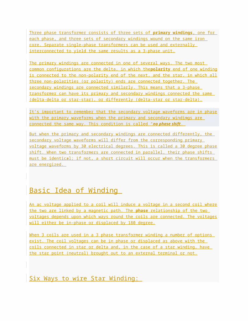
Six Ways to wire Star Winding :
Six Ways to wire Star Winding
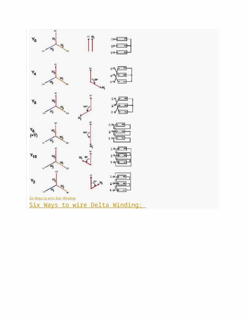
Six Ways to wire Delta Winding :
Six Ways to wire Delta Winding
Polarity
An AC voltage applied to a coil will induce a voltage in a second coil where the two are linked by a
magnetic path. The phase relationship of the two voltages depends upon which way round the coils
are connected. The voltages will either be in-phase or displaced by 180 deg.
When 3 coils are used in a 3 phase transformer winding a number of options exist. The coil voltages
can be in phase or displaced as above with the coils connected in star or delta and, in the case of a
star winding, have the star point (neutral) brought out to an external terminal or not.
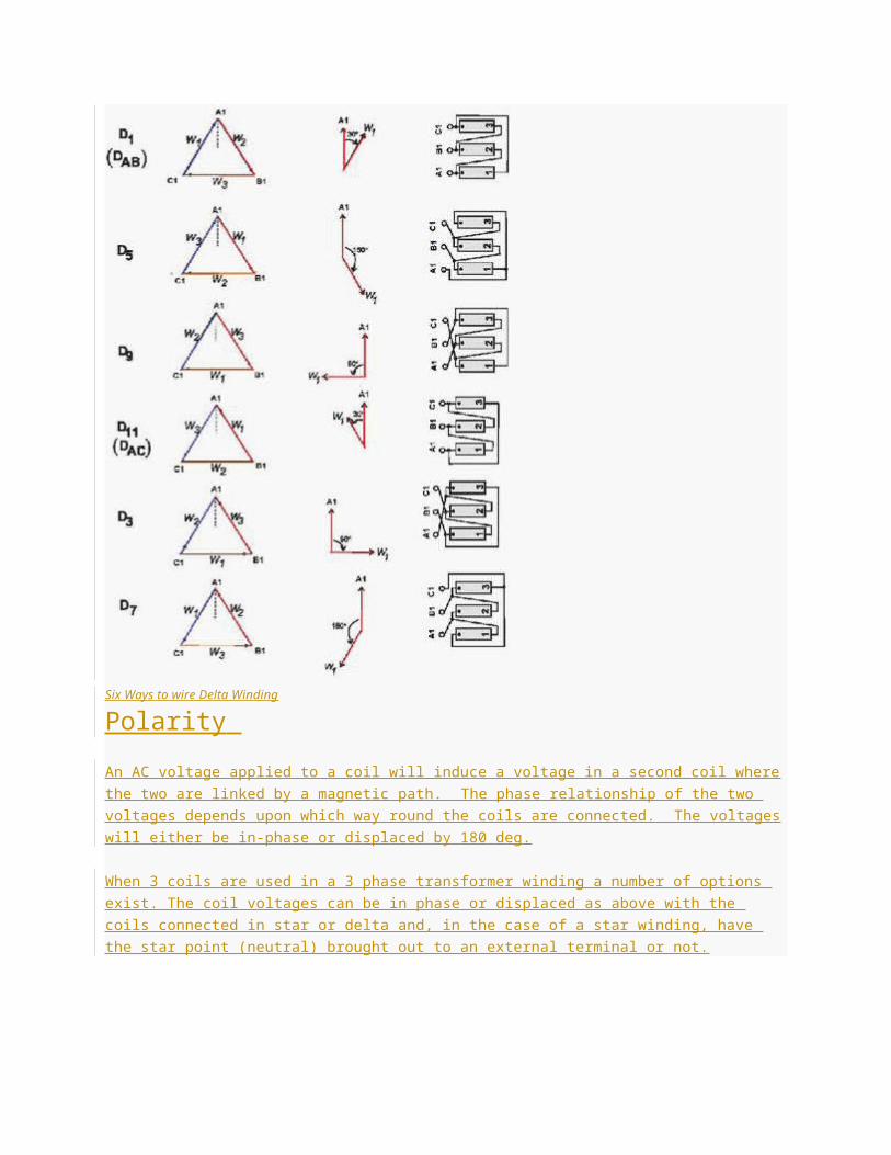
Additive and substractive polarity of transformer
When Pair of Coil of Transformer have same direction than voltage induced in both coil are in same
direction from one end to other end. When two coil have opposite winding direction than Voltage
induced in both coil are in opposite direction.
Winding connection designations
First Symbol: for High Voltage : Always capital letters.
D=Delta, S=Star, Z=Interconnected star, N=Neutral
Second Symbol: for Low voltage : Always Small letters.
d=Delta, s=Star, z=Interconnected star, n=Neutral.
Third Symbol: Phase displacement expressed as the clock hour number (1,6,11)
Example – Dyn11
Transformer has a delta connected primary winding ( D ) a star connected secondary ( y ) with the star
point brought out ( n ) and a phase shift of 30 deg leading ( 11 ).
The point of confusion is occurring in notation in a step-up transformer. As the IEC60076-1 standard
has stated, the notation is HV-LV in sequence. For example, a step-up transformer with a delta-
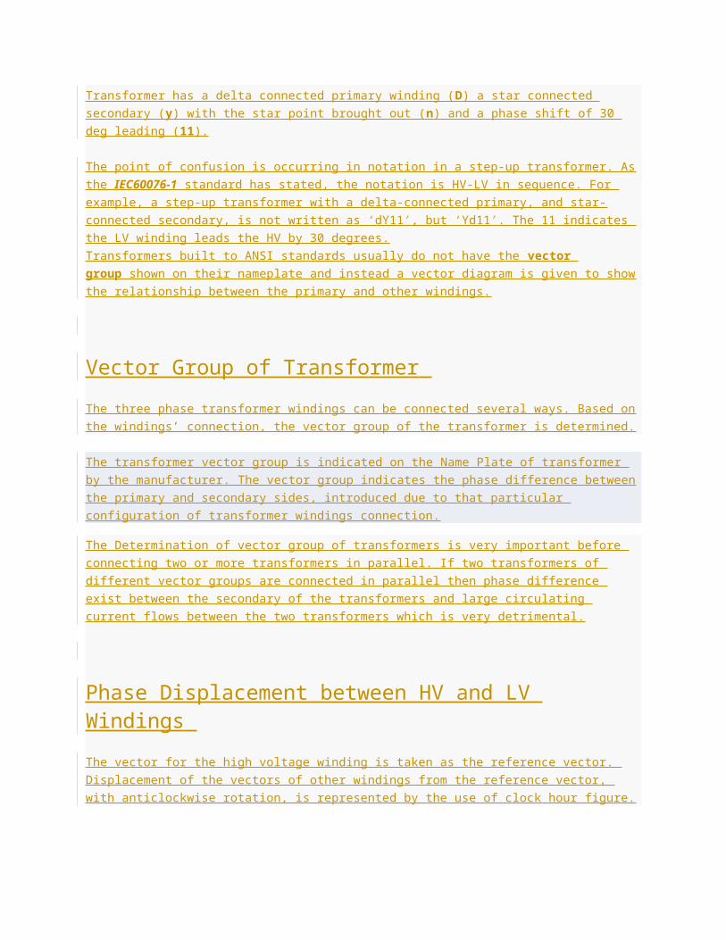
connected primary, and star-connected secondary, is not written as ‘dY11′, but ‘Yd11′. The 11 indicates
the LV winding leads the HV by 30 degrees.
Transformers built to ANSI standards usually do not have the vector group shown on their nameplate
and instead a vector diagram is given to show the relationship between the primary and other windings.
Vector Group of Transformer
The three phase transformer windings can be connected several ways. Based on the windings’
connection, the vector group of the transformer is determined.
The transformer vector group is indicated on the Name Plate of transformer by the manufacturer. The
vector group indicates the phase difference between the primary and secondary sides, introduced due
to that particular configuration of transformer windings connection.
The Determination of vector group of transformers is very important before connecting two or more
transformers in parallel. If two transformers of different vector groups are connected in parallel then
phase difference exist between the secondary of the transformers and large circulating current flows
between the two transformers which is very detrimental.
Phase Displacement between HV and LV Windings
The vector for the high voltage winding is taken as the reference vector. Displacement of the vectors of
other windings from the reference vector, with anticlockwise rotation, is represented by the use of clock
hour figure.
IS: 2026 (Part 1V)-1977 gives 26 sets of connections star-star, star-delta, and star zigzag, delta-delta,
delta star, delta-zigzag, zigzag star, zigzag-delta. Displacement of the low voltage winding vector varies
from zero to -330° in steps of -30°, depending on the method of connections.
Hardly any power system adopts such a large variety of connections. Some of the commonly used
connections with phase displacement of 0, -300, -180″ and -330° (clock-hour setting 0, 1, 6 and 11).
Symbol for the high voltage winding comes first, followed by the symbols of windings in diminishing
sequence of voltage. For example a 220/66/11 kV Transformer connected star, star and delta and
vectors of 66 and 11 kV windings having phase displacement of 0° and -330° with the reference (220
kV) vector will be represented As Yy0 – Yd11 .
The digits (0, 1, 11 etc) relate to the phase displacement between the HV and LV windings using a
clock face notation. The phasor representing the HV winding is taken as reference and set at 12
o’clock. Phase rotation is always anti-clockwise. (International adopted).
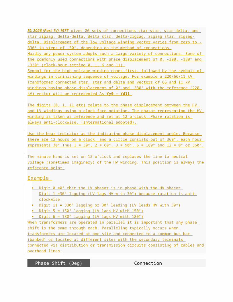
Use the hour indicator as the indicating phase displacement angle. Because there are 12 hours on a
clock, and a circle consists out of 360°, each hour represents 30°.Thus 1 = 30°, 2 = 60°, 3 = 90°, 6 =
180° and 12 = 0° or 360°.
The minute hand is set on 12 o’clock and replaces the line to neutral voltage (sometimes imaginary) of
the HV winding. This position is always the reference point.
Example
Digit 0 =0° that the LV phasor is in phase with the HV phasor
Digit 1 =30° lagging (LV lags HV with 30°) because rotation is anti-clockwise.
Digit 11 = 330° lagging or 30° leading (LV leads HV with 30°)
Digit 5 = 150° lagging (LV lags HV with 150°)
Digit 6 = 180° lagging (LV lags HV with 180°)
When transformers are operated in parallel it is important that any phase shift is the same through
each. Paralleling typically occurs when transformers are located at one site and connected to a
common bus bar (banked) or located at different sites with the secondary terminals connected via
distribution or transmission circuits consisting of cables and overhead lines.
Phase Shift (Deg) Connection
0 Yy0 Dd0 Dz0
30 lag Yd1 Dy1 Yz1
60 lag Dd2 Dz2
120 lag Dd4 Dz4
150 lag Yd5 Dy5 Yz5
180 lag Yy6 Dd6 Dz6
150 lead Yd7 Dy7 Yz7
120 lead Dd8 Dz8
60 lead Dd10 Dz10
30 lead Yd11 Dy11 Yz11
The phase-bushings on a three phase transformer are marked either ABC, UVW or 123 (HV-side
capital, LV-side small letters). Two winding, three phase transformers can be divided into four main
categories
Group O’clock TC
Group I 0 o’clock, 0° delta/delta, star/star
Group II 6 o’clock, 180° delta/delta, star/star
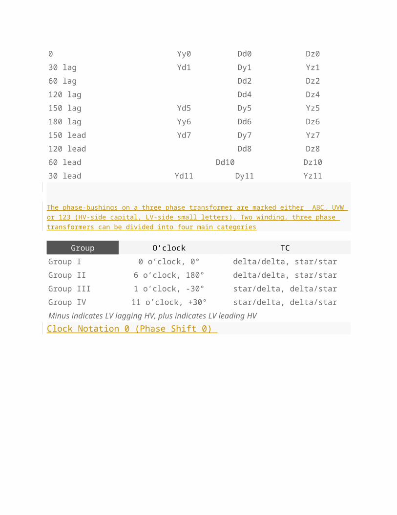
Group III 1 o’clock, -30° star/delta, delta/star
Group IV 11 o’clock, +30° star/delta, delta/star
Minus indicates LV lagging HV, plus indicates LV leading HV
Clock Notation 0 (Phase Shift 0)
Clock Notation 0 (Phase Shift 0)
Clock Notation 1 (Phase Shift -30)
Clock Notation 1 (Phase Shift -30)
Clock Notation 2 (Phase Shift -60)
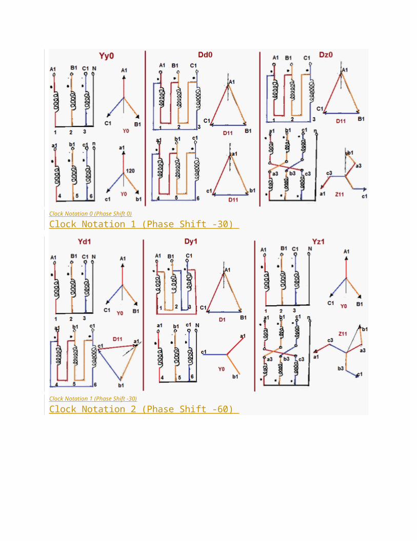
Clock Notation 2 (Phase Shift -60)
Clock Notation 4 (Phase Displacement -120)
Clock Notation 4 (Phase Displacement -120)
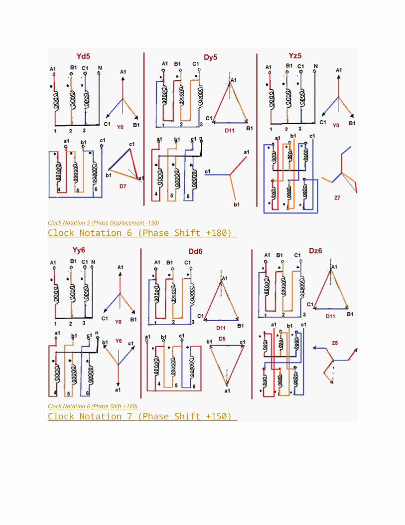
Clock Notation 5 (Phase Displacement -150)
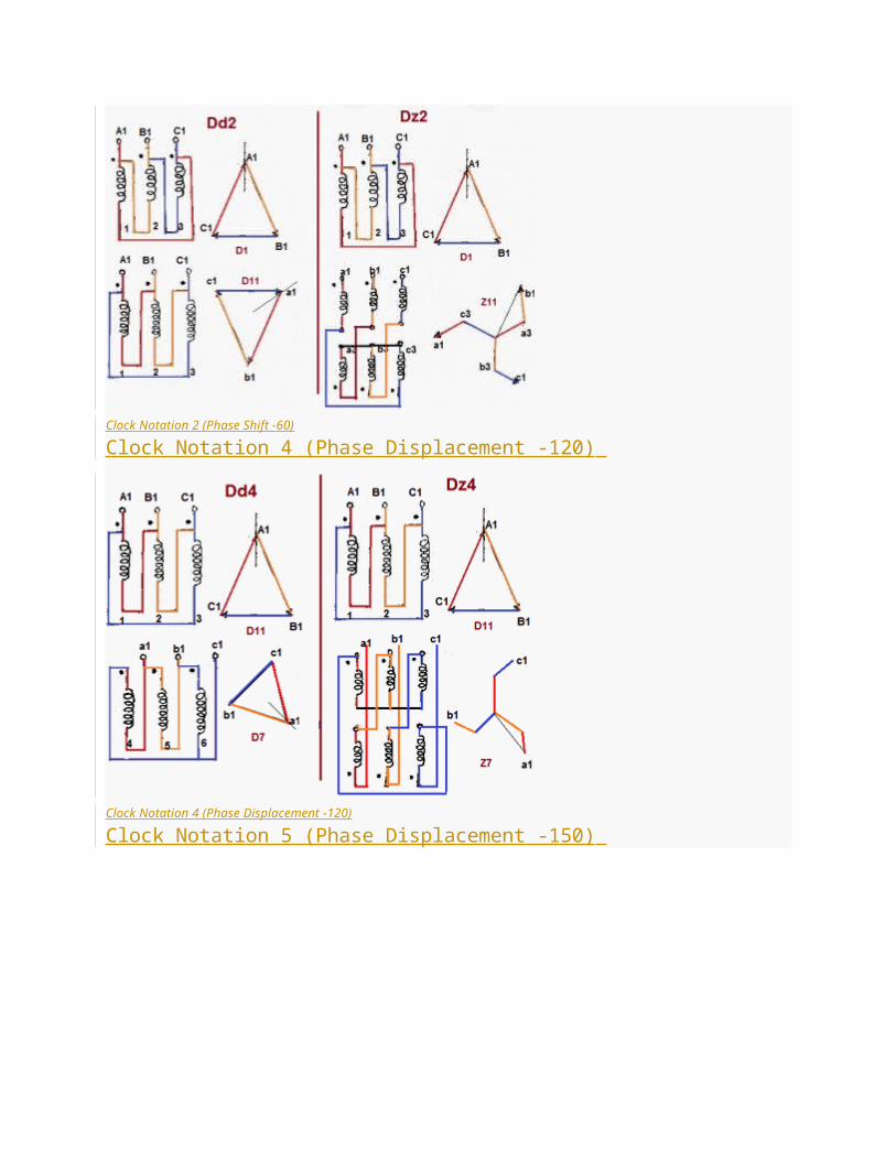
Clock Notation 5 (Phase Displacement -150)
Clock Notation 6 (Phase Shift +180)
Clock Notation 6 (Phase Shift +180)
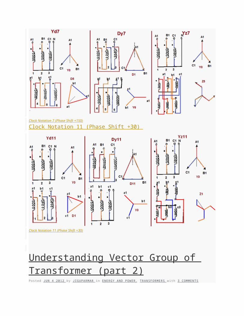
Clock Notation 7 (Phase Shift +150)
Clock Notation 7 (Phase Shift +150)
Clock Notation 11 (Phase Shift +30)
Clock Notation 11 (Phase Shift +30)
Understanding Vector Group of Transformer (part 2)Posted JUN 4 2012 by J IGUPARMAR in ENERGY AND POWER , TRANSFORMERS with 3 COMMENTS
Translate »
Get PDF »
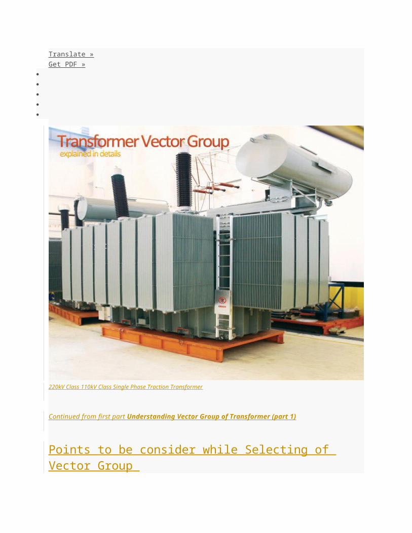
220kV Class 110kV Class Single Phase Traction Transformer
Continued from first part Understanding Vector Group of Transformer (part 1)
Points to be consider while Selecting of Vector Group
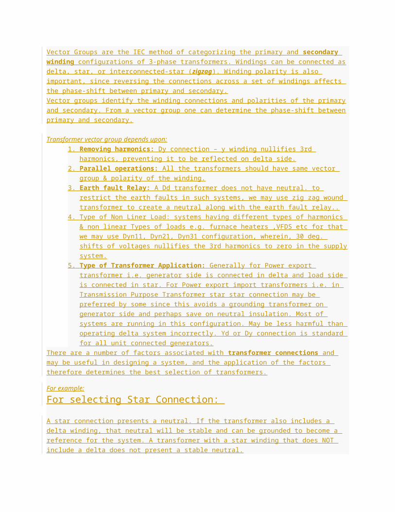
Vector Groups are the IEC method of categorizing the primary and secondary winding configurations
of 3-phase transformers. Windings can be connected as delta, star, or interconnected-star ( zigzag ).
Winding polarity is also important, since reversing the connections across a set of windings affects the
phase-shift between primary and secondary.
Vector groups identify the winding connections and polarities of the primary and secondary. From a
vector group one can determine the phase-shift between primary and secondary.
Transformer vector group depends upon:
1. Removing harmonics: Dy connection – y winding nullifies 3rd harmonics, preventing it to
be reflected on delta side.
2. Parallel operations: All the transformers should have same vector group & polarity of the
winding.
3. Earth fault Relay: A Dd transformer does not have neutral. to restrict the earth faults in
such systems, we may use zig zag wound transformer to create a neutral along with the
earth fault relay..
4. Type of Non Liner Load: systems having different types of harmonics & non linear Types of
loads e.g. furnace heaters ,VFDS etc for that we may use Dyn11, Dyn21, Dyn31
configuration, wherein, 30 deg. shifts of voltages nullifies the 3rd harmonics to zero in the
supply system.
5. Type of Transformer Application: Generally for Power export transformer i.e. generator
side is connected in delta and load side is connected in star. For Power export import
transformers i.e. in Transmission Purpose Transformer star star connection may be
preferred by some since this avoids a grounding transformer on generator side and perhaps
save on neutral insulation. Most of systems are running in this configuration. May be less
harmful than operating delta system incorrectly. Yd or Dy connection is standard for all unit
connected generators.
There are a number of factors associated with transformer connections and may be useful in
designing a system, and the application of the factors therefore determines the best selection of
transformers.
For example:
For selecting Star Connection:
A star connection presents a neutral. If the transformer also includes a delta winding, that neutral will
be stable and can be grounded to become a reference for the system. A transformer with a star winding
that does NOT include a delta does not present a stable neutral.
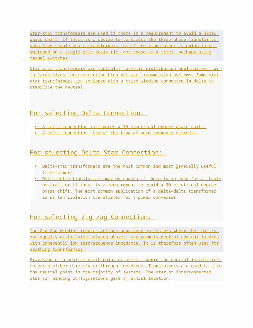
Star-star transformers are used if there is a requirement to avoid a 30deg phase shift, if there is a
desire to construct the three-phase transformer bank from single-phase transformers, or if the
transformer is going to be switched on a single-pole basis (ie, one phase at a time), perhaps using
manual switches.
Star-star transformers are typically found in distribution applications, or in large sizes interconnecting
high-voltage transmission systems. Some star-star transformers are equipped with a third winding
connected in delta to stabilize the neutral.
For selecting Delta Connection:
A delta connection introduces a 30 electrical degree phase shift.
A delta connection ‘traps’ the flow of zero sequence currents.
For selecting Delta-Star Connection:
Delta-star transformers are the most common and most generally useful transformers.
Delta-delta transformers may be chosen if there is no need for a stable neutral, or if there is a
requirement to avoid a 30 electrical degree phase shift. The most common application of a delta-
delta transformer is as tan isolation transformer for a power converter.
For selecting Zig zag Connection:
The Zig Zag winding reduces voltage unbalance in systems where the load is not equally distributed
between phases, and permits neutral current loading with inherently low zero-sequence impedance. It
is therefore often used for earthing transformers.
Provision of a neutral earth point or points, where the neutral is referred to earth either directly or
through impedance. Transformers are used to give the neutral point in the majority of systems. The star
or interconnected star (Z) winding configurations give a neutral location.
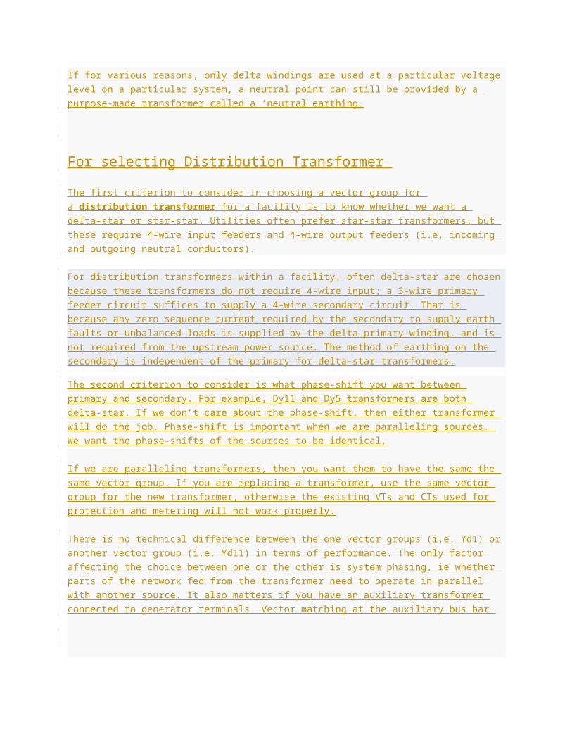
If for various reasons, only delta windings are used at a particular voltage level on a particular system,
a neutral point can still be provided by a purpose-made transformer called a ‘neutral earthing.
For selecting Distribution Transformer
The first criterion to consider in choosing a vector group for a distribution transformer for a facility is
to know whether we want a delta-star or star-star. Utilities often prefer star-star transformers, but these
require 4-wire input feeders and 4-wire output feeders (i.e. incoming and outgoing neutral conductors).
For distribution transformers within a facility, often delta-star are chosen because these transformers do
not require 4-wire input; a 3-wire primary feeder circuit suffices to supply a 4-wire secondary circuit.
That is because any zero sequence current required by the secondary to supply earth faults or
unbalanced loads is supplied by the delta primary winding, and is not required from the upstream power
source. The method of earthing on the secondary is independent of the primary for delta-star
transformers.
The second criterion to consider is what phase-shift you want between primary and secondary. For
example, Dy11 and Dy5 transformers are both delta-star. If we don’t care about the phase-shift, then
either transformer will do the job. Phase-shift is important when we are paralleling sources. We want
the phase-shifts of the sources to be identical.
If we are paralleling transformers, then you want them to have the same the same vector group. If you
are replacing a transformer, use the same vector group for the new transformer, otherwise the existing
VTs and CTs used for protection and metering will not work properly.
There is no technical difference between the one vector groups (i.e. Yd1) or another vector group (i.e.
Yd11) in terms of performance. The only factor affecting the choice between one or the other is system
phasing, ie whether parts of the network fed from the transformer need to operate in parallel with
another source. It also matters if you have an auxiliary transformer connected to generator terminals.
Vector matching at the auxiliary bus bar.
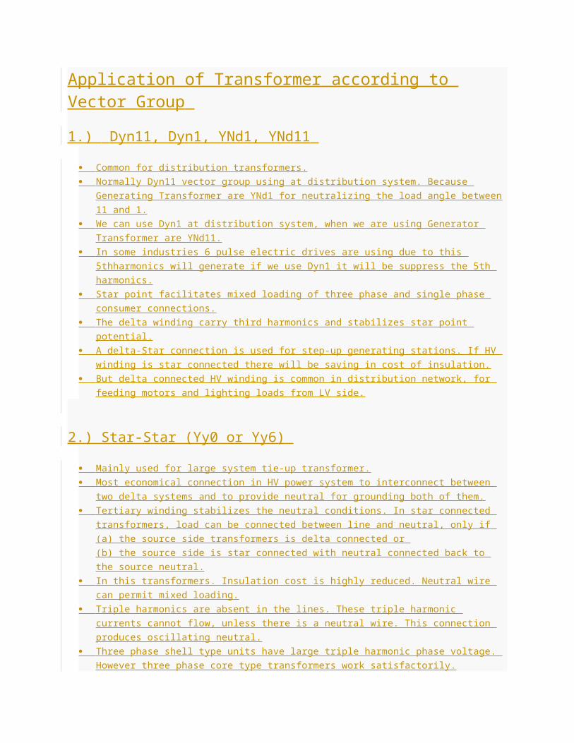
Application of Transformer according to Vector Group
1.) Dyn11, Dyn1, YNd1, YNd11
Common for distribution transformers.
Normally Dyn11 vector group using at distribution system. Because Generating Transformer are
YNd1 for neutralizing the load angle between 11 and 1.
We can use Dyn1 at distribution system, when we are using Generator Transformer are YNd11.
In some industries 6 pulse electric drives are using due to this 5thharmonics will generate if we
use Dyn1 it will be suppress the 5th harmonics.
Star point facilitates mixed loading of three phase and single phase consumer connections.
The delta winding carry third harmonics and stabilizes star point potential.
A delta-Star connection is used for step-up generating stations. If HV winding is star connected
there will be saving in cost of insulation.
But delta connected HV winding is common in distribution network, for feeding motors and
lighting loads from LV side.
2.) Star-Star (Yy0 or Yy6)
Mainly used for large system tie-up transformer.
Most economical connection in HV power system to interconnect between two delta systems and
to provide neutral for grounding both of them.
Tertiary winding stabilizes the neutral conditions. In star connected transformers, load can be
connected between line and neutral, only if
(a) the source side transformers is delta connected or
(b) the source side is star connected with neutral connected back to the source neutral.
In this transformers. Insulation cost is highly reduced. Neutral wire can permit mixed loading.
Triple harmonics are absent in the lines. These triple harmonic currents cannot flow, unless
there is a neutral wire. This connection produces oscillating neutral.
Three phase shell type units have large triple harmonic phase voltage. However three phase
core type transformers work satisfactorily.
A tertiary mesh connected winding may be required to stabilize the oscillating neutral due to third
harmonics in three phase banks.
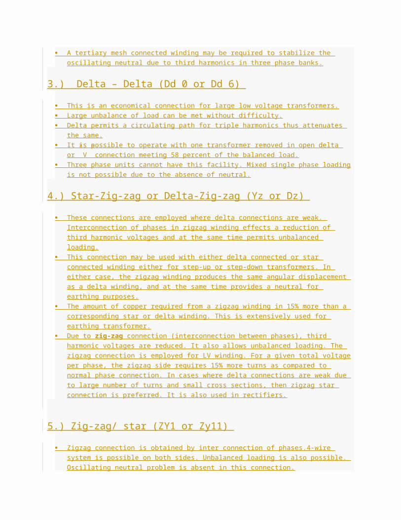
3.) Delta – Delta (Dd 0 or Dd 6)
This is an economical connection for large low voltage transformers.
Large unbalance of load can be met without difficulty.
Delta permits a circulating path for triple harmonics thus attenuates the same.
It is possible to operate with one transformer removed in open delta or” V” connection meeting
58 percent of the balanced load.
Three phase units cannot have this facility. Mixed single phase loading is not possible due to the
absence of neutral.
4.) Star-Zig-zag or Delta-Zig-zag (Yz or Dz)
These connections are employed where delta connections are weak. Interconnection of phases
in zigzag winding effects a reduction of third harmonic voltages and at the same time permits
unbalanced loading.
This connection may be used with either delta connected or star connected winding either for
step-up or step-down transformers. In either case, the zigzag winding produces the same
angular displacement as a delta winding, and at the same time provides a neutral for earthing
purposes.
The amount of copper required from a zigzag winding in 15% more than a corresponding star or
delta winding. This is extensively used for earthing transformer.
Due to zig-zag connection (interconnection between phases), third harmonic voltages are
reduced. It also allows unbalanced loading. The zigzag connection is employed for LV winding.
For a given total voltage per phase, the zigzag side requires 15% more turns as compared to
normal phase connection. In cases where delta connections are weak due to large number of
turns and small cross sections, then zigzag star connection is preferred. It is also used in
rectifiers.
5.) Zig-zag/ star (ZY1 or Zy11)
Zigzag connection is obtained by inter connection of phases.4-wire system is possible on both
sides. Unbalanced loading is also possible. Oscillating neutral problem is absent in this
connection.
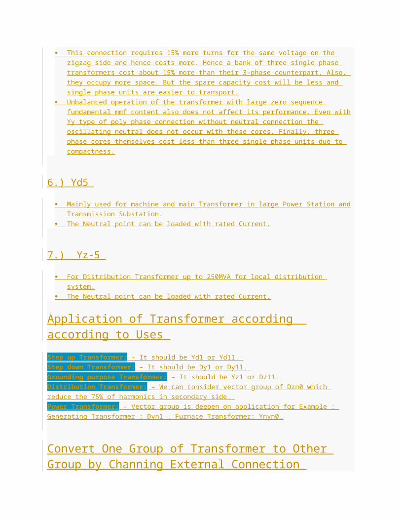
This connection requires 15% more turns for the same voltage on the zigzag side and hence
costs more. Hence a bank of three single phase transformers cost about 15% more than their 3-
phase counterpart. Also, they occupy more space. But the spare capacity cost will be less and
single phase units are easier to transport.
Unbalanced operation of the transformer with large zero sequence fundamental mmf content
also does not affect its performance. Even with Yy type of poly phase connection without neutral
connection the oscillating neutral does not occur with these cores. Finally, three phase cores
themselves cost less than three single phase units due to compactness.
6.) Yd5
Mainly used for machine and main Transformer in large Power Station and Transmission
Substation.
The Neutral point can be loaded with rated Current.
7.) Yz-5
For Distribution Transformer up to 250MVA for local distribution system.
The Neutral point can be loaded with rated Current.
Application of Transformer according according to Uses
Step up Transformer: – It should be Yd1 or Yd11.
Step down Transformer: – It should be Dy1 or Dy11.
Grounding purpose Transformer: – It should be Yz1 or Dz11.
Distribution Transformer: – We can consider vector group of Dzn0 which reduce the 75% of
harmonics in secondary side.
Power Transformer: – Vector group is deepen on application for Example : Generating Transformer :
Dyn1 , Furnace Transformer: Ynyn0.
Convert One Group of Transformer to Other Group by Channing External Connection
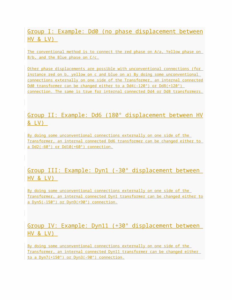
Group I: Example: Dd0 (no phase displacement between HV & LV)
The conventional method is to connect the red phase on A/a, Yellow phase on B/b, and the Blue phase
on C/c.
Other phase displacements are possible with unconventional connections (for instance red on b, yellow
on c and blue on a) By doing some unconventional connections externally on one side of the
Transformer, an internal connected Dd0 transformer can be changed either to a Dd4(-120°) or
Dd8(+120°) connection. The same is true for internal connected Dd4 or Dd8 transformers.
Group II: Example: Dd6 (180° displacement between HV & LV)
By doing some unconventional connections externally on one side of the Transformer, an internal
connected Dd6 transformer can be changed either to a Dd2(-60°) or Dd10(+60°) connection.
Group III: Example: Dyn1 (-30° displacement between HV & LV)
By doing some unconventional connections externally on one side of the Transformer, an internal
connected Dyn1 transformer can be changed either to a Dyn5(-150°) or Dyn9(+90°) connection.
Group IV: Example: Dyn11 (+30° displacement between HV & LV)
By doing some unconventional connections externally on one side of the Transformer, an internal
connected Dyn11 transformer can be changed either to a Dyn7(+150°) or Dyn3(-90°) connection.
Point to be remembered
For Group-III & Group-IV: By doing some unconventional connections externally on both sides
of the Transformer, an internal connected Group-III or Group-IV transformer can be changed to
any of these two groups.
Thus by doing external changes on both sides of the Transformer an internal connected Dyn1
transformer can be changed to either a: Dyn3, Dyn5, Dyn7, Dyn9 or Dyn11 transformer, This is
just true for star/delta or delta/star connections.
For Group-I & Group-II: Changes for delta/delta or star/star transformers between Group-I and
Group-III can just be done internally.
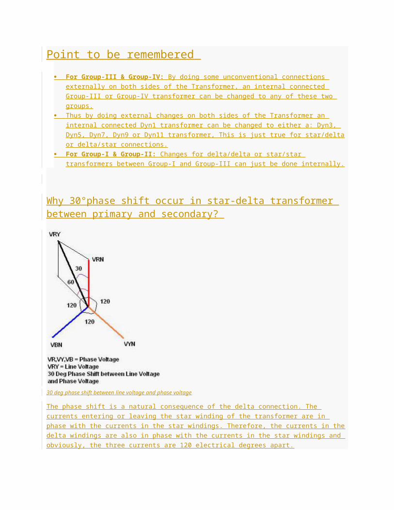
Why 30°phase shift occur in star-delta transformer between primary and secondary?
30 deg phase shift between line voltage and phase voltage
The phase shift is a natural consequence of the delta connection. The currents entering or leaving the
star winding of the transformer are in phase with the currents in the star windings. Therefore, the
currents in the delta windings are also in phase with the currents in the star windings and obviously, the
three currents are 120 electrical degrees apart.
But the currents entering or leaving the transformer on the delta side are formed at the point where two
of the windings comprising the delta come together – each of those currents is the phasor sum of the
currents in the adjacent windings.
When you add together two currents that are 120 electrical degrees apart, the sum is inevitably shifted
by 30 degrees.
The Main reason for this phenomenon is that the phase voltage lags line current by
30degrees.consider a delta/star transformer. The phase voltages in three phases of both primary and
secondary. you will find that in primary the phase voltage and line voltages are same, let it be VRY
(take one phase). But, the corresponding secondary will have the phase voltage only in its phase
winding as it is star connected. the line voltage of star connected secondary and delta connected
primary won’t have any phase differences between them. so this can be summarized that “the phase
shift is associated with the wave forms of the three phase windings.
This is the HV Side or the Switchyard side of the Generator Transformer is connected in Delta and the
LV Side or the generator side of the GT is connected in Star, with the Star side neutral brought out.
The LV side voltage will “lag” the HV side voltage by 30 degrees. Thus, in a generating station we
create a 30 degrees lagging voltage for transmission, with respect to the generator voltage.
As we have created a 30 degrees lagging connection in the generating station, it is advisable to create
a 30 degrees leading connection in distribution so that the user voltage is “in phase” with the generated
voltage. And, as the transmission side is Delta and the user might need three phase, four-wire in the LV
side for his single phase loads, the distribution transformer is chosen as Dyn11.
There is magnetic coupling between HT and LT. When the load side (LT) suffers some dip the LT
current try to go out of phase with HT current, so 30 degree phase shift in Dyn-11 keeps the two
currents in phase when there is dip.
So the vector group at the generating station is important while selecting distribution Transformer.
Vector Group in Generating-Transmission-Distribution System
Generating TC is Yd1 transmitted power at 400KV, for 400KV to 220KV Yy is used and by
using Yd between e.g. 220 and 66 kV, then Dy from 66 to 11 kV so that their phase shifts can be
cancelled out. And for LV (400/230V) supplies at 50 Hz are usually 3 phase, earthed neutral, so a “Dyn”
LV winding is needed. Here GT side -30lag (Yd1) can be nullify +30 by using distribution Transformer
of Dy11.
A reason for using Yd between e.g. 220 and 66 kV, then Dy from 66 to 11 kV is that their phase shifts
can cancel out and It is then also possible to parallel a 220/11 kV YY transformer, at 11 kV, with the
66/11 kV (a YY transformer often has a third, delta, winding to reduce harmonics).
If one went Dy11 – Dy11 from 220 to 11 kV, there would be a 60 degree shift, which is not possible in
one transformer. The “standard” transformer groups in distribution avoid that kind of limitation, as a
result of thought and experience leading to lowest cost over many years.
Generator TC is Yd1, can we use Distribution TC Dy5 instead of Dy11?
With regards to theory, there are no special advantages of Dyn11 over Dyn5.
In Isolation Application: -In isolated applications there is no advantage or disadvantage by using Dy5
or Dy11. If however we wish to interconnect the secondary sides of different Dny transformers, we must
have compatible transformers, and that can be achieved if you have a Dyn11 among a group of Dyn5′s
and vice versa.
In Parallel Connection: – Practically, the relative places of the phases remain same in Dyn11
compared to Dyn5.
If we use Yd1 Transformer on Generating Side and Distribution side Dy11 transformer than -30 lag of
generating side (Yd1) is nullify by +30 Lead at Receiving side Dy11) so no phase difference respect to
generating Side and if we are on the HV side of the Transformer, and if we denote the phases as R- Y-
B from left to right, the same phases on the LV side will be R- Y -B, but from left to Right.
This will make the Transmission lines have same color (for identification) whether it is input to or output
from the Transformer.
If we use Yd1 Transformer on Generating Side and Distribution side Dy5 transformer than -30 lag of
generating side (Yd1) is more lag by -150 Lag at Receiving side (Dy5) so Total phase difference
respect to generating Side is 180 deg (-30+-150=-180) and if we are on the HV side of the Transformer,
and if we denote the phases as R- Y-B from left to right, the same phases on the LV side will be R- Y -
B, but from Right to Left.
This will make the Transmission lines have No same color (for identification) whether it is input to or
output from the Transformer. The difference in output between the Dyn11 and Dny5 and is therefore
180 degrees.
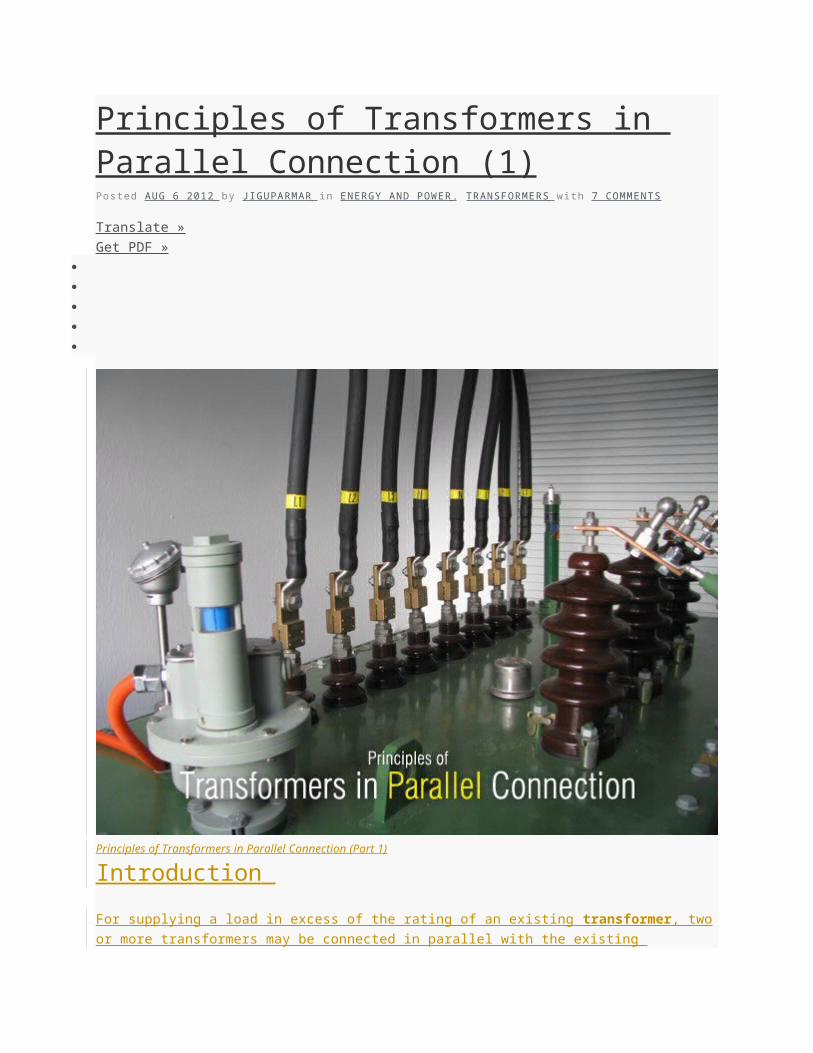
Principles of Transformers in Parallel Connection (1)Posted AUG 6 2012 by J IGUPARMAR in ENERGY AND POWER , TRANSFORMERS with 7 COMMENTS
Translate »
Get PDF »
Principles of Transformers in Parallel Connection (Part 1)
Introduction
For supplying a load in excess of the rating of an existing transformer , two or more transformers may
be connected in parallel with the existing transformer. The transformers are connected in parallel when
load on one of the transformers is more than its capacity. The reliability is increased with parallel
operation than to have single larger unit. The cost associated with maintaining the spares is less when
two transformers are connected in parallel.
It is usually economical to install another transformer in parallel instead of replacing the existing
transformer by a single larger unit. The cost of a spare unit in the case of two parallel transformers (of
equal rating) is also lower than that of a single large transformer . In addition, it is preferable to have a
parallel transformer for the reason of reliability.
With this at least half the load can be supplied with one transformer out of service.
Condition for Parallel Operation of Transformer
For parallel connection of transformers, primary windings of the Transformers are connected to source
bus-bars and secondary windings are connected to the load bus-bars.
Various conditions that must be fulfilled for the successful parallel operation of transformers:
1. Same voltage and Turns Ratio (both primary and secondary voltage rating is same)
2. Same Percentage Impedance and X/R ratio
3. Identical Position of Tap changer
4. Same KVA ratings
5. Same Phase angle shift ( vector group are same)
6. Same Frequency rating
7. Same Polarity
8. Same Phase sequence
Some of these conditions are convenient and some are mandatory .
The convenient conditions are: Same voltage Ratio and Turns Ratio, Same Percentage Impedance,
Same KVA Rating, Same Position of Tap changer.
The mandatory conditions conditions are: Same Phase Angle Shift, Same Polarity, Same Phase
Sequence and Same Frequency. When the convenient conditions are not met paralleled operation is
possible but not optimal.
1. Same voltage Ratio and Turns Ratio (on each tap)
If the transformers connected in parallel have slightly different voltage ratios, then due to the inequality
of induced emfs in the secondary windings, a circulating current will flow in the loop formed by the
secondary windings under the no-load condition, which may be much greater than the normal no-load
current.
The current will be quite high as the leakage impedance is low. When the secondary windings are
loaded, this circulating current will tend to produce unequal loading on the two transformers, and it may
not be possible to take the full load from this group of two parallel transformers (one of the transformers
may get overloaded).
If two transformers of different voltage ratio are connected in parallel with same primary supply voltage,
there will be a difference in secondary voltages.
Now when the secondary of these transformers are connected to same bus, there will be a circulating
current between secondary’s and therefore between primaries also. As the internal impedance of
transformer is small, a small voltage difference may cause sufficiently high circulating current causing
unnecessary extra I 2 R loss.
The ratings of both primaries and secondary’s should be identical. In other words, the transformers
should have the same turn ratio i.e. transformation ratio.
2. Same percentage impedance and X/R ratio
If two transformers connected in parallel with similar per-unit impedances they will mostly share
the load in the ration of their KVA ratings. Here Load is mostly equal because it is possible to have two
transformers with equal per-unit impedances but different X/R ratios. In this case the line current will be
less than the sum of the transformer currents and the combined capacity will be reduced accordingly.
A difference in the ratio of the reactance value to resistance value of the per unit impedance results in a
different phase angle of the currents carried by the two paralleled transformers; one transformer will be
working with a higher power factor and the other with a lower power factor than that of the combined
output. Hence, the real power will not be proportionally shared by the transformers.
The current shared by two transformers running in parallel should be proportional to their MVA
ratings.
The current carried by these transformers are inversely proportional to their internal impedance.
From the above two statements it can be said that impedance of transformers running in parallel are
inversely proportional to their MVA ratings. In other words percentage impedance or per unit values of
impedance should be identical for all the transformers run in parallel.
When connecting single-phase transformers in three-phase banks, proper impedance matching
becomes even more critical. In addition to following the three rules for parallel operation, it is also a
good practice to try to match the X/R ratios of the three series impedances to keep the three-phase
output voltages balanced.
When single-phase transformers with the same KVA ratings are connected in a Y-∆ Bank, impedance
mismatches can cause a significant load unbalance among the transformers
Lets examine following different type of case among Impedance, Ratio and KVA.
If single-phase transformers are connected in a Y-Y bank with an isolated neutral, then the magnetizing
impedance should also be equal on an ohmic basis. Otherwise, the transformer having the largest
magnetizing impedance will have a highest percentage of exciting voltage, increasing the core losses
of that transformer and possibly driving its core into saturation.
Case 1: Equal Impedance, Ratios and Same kVA
The standard method of connecting transformers in parallel is to have the same turn ratios, percent
impedances, and kVA ratings. Connecting transformers in parallel with the same parameters results in
equal load sharing and no circulating currents in the transformer windings.
Example Connecting two 2000 kVA, 5.75% impedance transformers in parallel, each with the same
turn ratios to a 4000 kVA load.
Loading on the transformers-1 =KVA1=[( KVA1 / %Z) / ((KVA1 / %Z1)+ (KVA2 / %Z2))]X KVAl
kVA1 = 348 / (348 + 348) x 4000 kVA = 2000 kVA.
Loading on the transformers-2 =KVA1=[( KVA2 / %Z) / ((KVA1 / %Z1)+ (KVA2 / %Z2))]X KVAl
kVA2 = 348 / (348 + 348) x 4000 kVA = 2000 kVA
Hence KVA1=KVA2=2000KVA
Case 2: Equal Impedances, Ratios and Different kVA
This Parameter is not in common practice for new installations, sometimes two transformers with
different kVAs and the same percent impedances are connected to one common bus. In this situation,
the current division causes each transformer to carry its rated load. There will be no circulating currents
because the voltages (turn ratios) are the same.
Example Connecting 3000 kVA and 1000 kVA transformers in parallel, each with 5.75% impedance,
each with the same turn ratios, connected to a common 4000 kVA load.
Loading on Transformer-1=kVA1 = 522 / (522 + 174) x 4000 = 3000 kVA
Loading on Transformer-1=kVA2 = 174 / (522 + 174) x 4000 = 1000 kVA
From above calculation it is seen that different kVA ratings on transformers connected to one common
load, that current division causes each transformer to only be loaded to its kVA rating. The key here is
that the percent impedance are the same.
Case 3: Unequal Impedance but Same Ratios and kVA
Mostly used this Parameter to enhance plant power capacity by connecting existing transformers in
parallel that have the same kVA rating, but with different percent impedances.
This is common when budget constraints limit the purchase of a new transformer with the same
parameters.
We need to understand is that the current divides in inverse proportions to the impedances, and larger
current flows through the smaller impedance. Thus, the lower percent impedance transformer can be
overloaded when subjected to heavy loading while the other higher percent impedance transformer will
be lightly loaded.
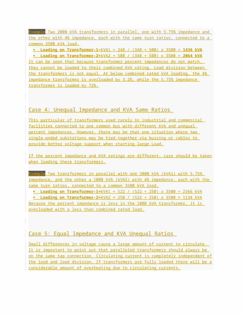
Example Two 2000 kVA transformers in parallel, one with 5.75% impedance and the other with 4%
impedance, each with the same turn ratios, connected to a common 3500 kVA load.
Loading on Transformer-1 =kVA1 = 348 / (348 + 500) x 3500 = 1436 kVA
Loading on Transformer-2= kVA2 = 500 / (348 + 500) x 3500 = 2064 kVA
It can be seen that because transformer percent impedances do not match, they cannot be loaded to
their combined kVA rating. Load division between the transformers is not equal. At below combined
rated kVA loading, the 4% impedance transformer is overloaded by 3.2%, while the 5.75% impedance
transformer is loaded by 72%.
Case 4: Unequal Impedance and KVA Same Ratios
This particular of transformers used rarely in industrial and commercial facilities connected to one
common bus with different kVA and unequal percent impedances. However, there may be that one
situation where two single-ended substations may be tied together via bussing or cables to provide
better voltage support when starting large Load.
If the percent impedance and kVA ratings are different, care should be taken when loading these
transformers.
Example Two transformers in parallel with one 3000 kVA (kVA1) with 5.75% impedance, and the other
a 1000 kVA (kVA2) with 4% impedance, each with the same turn ratios, connected to a common 3500
kVA load.
Loading on Transformer-1= kVA1 = 522 / (522 + 250) x 3500 = 2366 kVA
Loading on Transformer-2= kVA2 = 250 / (522 + 250) x 3500 = 1134 kVA
Because the percent impedance is less in the 1000 kVA transformer, it is overloaded with a less than
combined rated load.
Case 5: Equal Impedance and KVA Unequal Ratios
Small differences in voltage cause a large amount of current to circulate. It is important to point out that
paralleled transformers should always be on the same tap connection. Circulating current is completely
independent of the load and load division. If transformers are fully loaded there will be a considerable
amount of overheating due to circulating currents.
The Point which should be Remember that circulating currents do not flow on the line, they cannot be
measured if monitoring equipment is upstream or downstream of the common connection points.
Example Two 2000 kVA transformers connected in parallel, each with 5.75% impedance, same X/R
ratio (8), transformer 1 with tap adjusted 2.5% from nominal and transformer 2 tapped at nominal. What
is the percent circulating current (%IC)
%Z1 = 5.75, So %R’ = %Z1 / √[(X/R)2 + 1)] = 5.75 / √((8)2 + 1)=0.713
%R1 = %R2 = 0.713
%X1 = %R x (X/R)=%X1= %X2= 0.713 x 8 = 5.7
Let %e = difference in voltage ratio expressed in percentage of normal and k = kVA1/ kVA2
Circulating current %IC = %eX100 / √ (%R1+k%R2)2 + (%Z1+k%Z2)2.
%IC = 2.5X100 / √ (0.713 + (2000/2000)X0.713)2 + (5.7 + (2000/2000)X5.7)2
%IC = 250 / 11.7 = 21.7
The circulating current is 21.7% of the full load current .
Case 6: Unequal Impedance, KVA and Different Ratios
This type of parameter would be unlikely in practice. If both the ratios and the impedance are different,
the circulating current (because of the unequal ratio) should be combined with each transformer’s share
of the load current to obtain the actual total current in each unit.
For unity power factor, 10% circulating current (due to unequal turn ratios) results in only half percent to
the total current. At lower power factors, the circulating current will change dramatically.
Example Two transformers connected in parallel, 2000 kVA1 with 5.75% impedance, X/R ratio of 8,
1000 kVA2 with 4% impedance, X/R ratio of 5, 2000 kVA1 with tap adjusted 2.5% from nominal and
1000 kVA2 tapped at nominal.
%Z1 = 5.75, So %R’ = %Z1 / √[(X/R)2 + 1)] = 5.75 / √((8)2 + 1)=0.713
%X1= %R x (X/R)=0.713 x 8 = 5.7
%Z2= 4, So %R2 = %Z2 /√ [(X/R)2 + 1)]= 4 / √((5)2 + 1) =0.784
%X2 = %R x (X/R)=0.784 x 5 = 3.92
Let %e = difference in voltage ratio expressed in percentage of normal and k = kVA1/ kVA2
Circulating current %IC = %eX100 / √ (%R1+k%R2)2 + (%Z1+k%Z2)2.
%IC = 2.5X100 / √ (0.713 + (2000/2000)X0.713)2 + (5.7 + (2000/2000)X5.7)2
%IC = 250 / 13.73 = 18.21.
The circulating current is 18.21% of the full load current .
3. Same polarity
Polarity of transformer means the instantaneous direction of induced emf in secondary. If the
instantaneous directions of induced secondary emf in two transformers are opposite to each other
when same input power is fed to the both of the transformers, the transformers are said to be in
opposite polarity.
The transformers should be properly connected with regard to their polarity. If they are connected with
incorrect polarities then the two EMFs, induced in the secondary windings which are in parallel, will act
together in the local secondary circuit and produce a short circuit.
Polarity of all transformers run in parallel should be same otherwise huge circulating current flows in the
transformer but no load will be fed from these transformers.
If the instantaneous directions of induced secondary emf in two transformers are same when same
input power is fed to the both of the transformers, the transformers are said to be in same polarity.
4. Same phase sequence
The phase sequence of line voltages of both the transformers must be identical for parallel operation of
three-phase transformers. If the phase sequence is an incorrect, in every cycle each pair of phases will
get short-circuited.
This condition must be strictly followed for parallel operation of transformers.
5. Same phase angle shift (zero relative phase displacement between the secondary line voltages)
The transformer windings can be connected in a variety of ways which produce different magnitudes
and phase displacements of the secondary voltage. All the transformer connections can be classified
into distinct vector groups.
Group 1: Zero phase displacement (Yy0, Dd0, Dz0)
Group 2: 180° phase displacement (Yy6, Dd6, Dz6)
Group 3: -30° phase displacement (Yd1, Dy1, Yz1)
Group 4: +30° phase displacement (Yd11, Dy11, Yz11)
In order to have zero relative phase displacement of secondary side line voltages, the transformers
belonging to the same group can be paralleled. For example, two transformers with Yd1 and Dy1
connections can be paralleled.
The transformers of groups 1 and 2 can only be paralleled with transformers of their own group.
However, the transformers of groups 3 and 4 can be paralleled by reversing the phase sequence of one
of them. For example, a transformer with Yd1 1 connection (group 4) can be paralleled with that having
Dy1 connection (group 3) by reversing the phase sequence of both primary and secondary terminals of
the Dy1 transformer.
We can only parallel Dy1 and Dy11 by crossing two incoming phases and the same two outgoing
phases on one of the transformers, so if we have a DY11 transformer we can cross B&C phases on the
primary and secondary to change the +30 degree phase shift into a -30 degree shift which will parallel
with the Dy1, assuming all the other points above are satisfied.
6. Same KVA ratings
If two or more transformer is connected in parallel, then load sharing % between them is according to
their rating. If all are of same rating, they will share equal loads
Transformers of unequal kVA ratings will share a load practically (but not exactly) in proportion to their
ratings, providing that the voltage ratios are identical and the percentage impedances (at their own kVA
rating) are identical, or very nearly so in these cases a total of than 90% of the sum of the two ratings is
normally available.
It is recommended that transformers, the kVA ratings of which differ by more than 2:1, should not be
operated permanently in parallel.
Transformers having different kva ratings may operate in parallel, with load division such that each
transformer carries its proportionate share of the total load To achieve accurate load division, it is
necessary that the transformers be wound with the same turns ratio, and that the percent impedance of
all transformers be equal, when each percentage is expressed on the kva base of its respective
transformer. It is also necessary that the ratio of resistance to reactant in all transformers be equal.
For satisfactory operation the circulating current for any combinations of ratios and impedance probably
should not exceed ten percent of the full-load rated current of the smaller unit.
7. Identical tap changer and its operation
The only important point to be remembered is the tap changing switches must be at same position for
all the three transformers and should check and confirm that the secondary voltages are same.
When the voltage tap need change all three tap changing switches should be operated identical for all
transformers. The OL settings of the SF6 also should be identical. If the substation is operating on full
load condition, tripping of one transformer can cause cascade tripping of all three transformers.
In transformers Output Voltage can be controlled either by Off Circuit Tap Changer (Manual tap
changing) or By On – Load Tap Changer-OLTC (Automatic Changing).
In the transformer with OLTC, it is a closed loop system, with following components:
1. AVR (Automatic Voltage Regulator) – an electronic programmable device). With this
AVR we can set the Output Voltage of the transformers. The Output Voltage of the transformer is fed
into the AVR through the LT Panel. The AVR Compares the SET voltage and the Output Voltage and
gives the error signals, if any, to the OLTC through the RTCC Panel for tap changing. This AVR is
mounted in the RTCC.
2. RTCC (Remote Tap Changing Cubicle) – This is a panel consisting of the AVR,
Display for Tap Position, Voltage, and LEDs for Raise and Lower of Taps relays, Selector Switches for
Auto Manual Selection… In AUTO MODE the voltage is controlled by the AVR. In manual Mode the
operator can Increase / decrease the voltage by changing the Taps manually through the Push Button
in the RTCC.
3. OLTC is mounted on the transformer - It consists of a motor, controlled by the
RTCC, which changes the Taps in the transformers.
Both the Transformers should have same voltage ratio at all the taps and when you run transformers in
parallel, it should operate as same tap position. If we have OLTC with RTCC panel, one RTCC should
work as master and other should work as follower to maintain same tap positions of transformer.
However, a circulating current can be flown between the two tanks if the impedances of the two
transformers are different or if the taps of the on-load tap changer (OLTC) are mismatched temporarily
due to the mechanical delay. The circulating current may cause the malfunction of protection relays.


![Understanding and Improving Transformer From a Multi ...yplu/pub/TransformerODE.pdf · The Transformer architecture is usually developed by stacking Transformer layers [3, 7]. A Trans-](https://img.pdfslide.us/doc/110x75/5e041ce971302740e4025b95/understanding-and-improving-transformer-from-a-multi-yplupubtransformerodepdf.jpg)