Embed Size (px)
Citation preview
8/3/2019 Underground Distributed Line
http://slidepdf.com/reader/full/underground-distributed-line 1/17
----------------------- Page 1-----------------------
TM 5-811-1/AFJMAN 32-1080
CHAPTER 7
UNDERGROUND DISTRIBUTION LINES
7-1. General. multiple conductor, metallic or non-metallicUnderground lines will be provided only in those sheathed. Nonmetallic sheathed cable 2,000 volt toareas as established in chapter 5. Underground 5,000volt rating shall be shielded.line installation will be coordinated with the in-(b) Above 5,000 volts-copper, metallic, or
stallation master plan to avoid conflict with con- non-metallic sheathed, single or multiple conduc-
struction of future facilities. Lines will normally tor, shielded cable.be installed adjacent to roadways in urban, hous-(c) Aluminum conductors of equivalent am-
ing, or industrial plant areas, but may be routed pacities may be used in lieu of No. 4 AWG copperas required to meet the project objectives. A and larger copper conductors.careful study will be made of all underground(d) Aluminum conductors shall be termi-
utilities in order to ensure a minimum of interfer- natedin compression type lugs or connectors tilledence between electrical lines and other under- with
high temperature, oxide inhibitor compound.ground utilities, whether existing, being con-(3) Cable installation. All primary under-structed, or proposed as a definite future ground
cables shall be installed in concrete en-construction project. Electrical lines will be at casednon-metallic ducts or concrete encased galva-least six feet from any steam or hot water lines, nizedrigid steel conduits except as follows. Steel
except at crossings where a one-foot separation conduit, which is not concrete encased, shall befrom such lines is adequate. corros
ion proof-coated (PVC, etc.) and shall bea. Symbols and codes. For uniformity, symbols employed only for short runs between buildings orwill comply with ANSI Y32.9. Installation will under
paved areas. Direct buried ducts or directcomply with the requirements of the NESC and buried
cables may be employed for primary distri-the NEC as required. Where state safety rules are bution
(above 600 V) feeders located in areaspredominantly accepted, such rules may be used whichare remote to normal pedestrian and vehicleprovided they are as stringent as those of the traffic. Consider using a direct buried, flexible
NESC. polyethylene cable, duct type conduit with self
b. Construction and other conditions. Typical contai
8/3/2019 Underground Distributed Line
http://slidepdf.com/reader/full/underground-distributed-line 2/17
ned cable to allow easier replacement. Con-underground construction details are shown later cretemarkers shall be provided at approximately
in this chapter. Service conditions are covered in 200foot intervals and at each change in directionchapter 1. Grounding and surge protection are to indicate the location of underground cable
covered in chapter 9. Other conditions will follow route.Direct buried cable or cable duct, which is
the guidelines established by the NESC, the Rural notconcrete and metallic conduit encased, shouldElectrification Authority (REA), or the local utility be marked with a metallic/magnetic warning tapeas applicable. Underground cable systems may buried
six to twelve inches below the surface andemploy manholes or above-ground sectionalizing abovethe cable or duct. Cable warning tape shall
and pulling cabinets depending on local geological be redor orange in color.
conditions, potential for damage from vehicles and7-2.
Cable.the required design life of the facility.
c. Air Force underground installations. Conductor material and insulation type will be
(1) Secondary distribution. All secondary un- specified. Restricting extensions of existing sys-derground cables may be installed in either con- temsto a specific conductor material and insula-crete encased ducts or direct burial type ducts or tiontype in order to match an existing cable type
conduit, or they may be direct burial type cables. is permitted only when a need has been estab-Direct burial plastic conduit may be utilized when lished. Neutral cables, where required, will becable temperature conditions are within the con- installed with 600 V insulation unless concentricduit rating and where the conduit is not under neutral cable is used. In duct lines, neutrals willlarge paved areas or building structures. Conduc- be installed in the same conduit with associatedtors shall be copper, although aluminum may be phasecables.used in lieu of copper conductors No. 4 AWG and a.Conductor material. Since underground con-
larger. ductors are continuously supported, soft-drawn cop-
(2) Primary distribution. peror aluminum alloy 5005 provides adequate
(a) 5,000 volts or less-copper, single or strength. However, the selection of copper or alu-
7-1
----------------------- Page 2-----------------------
TM 5-811-1/AFJMAN 32-1080
8/3/2019 Underground Distributed Line
http://slidepdf.com/reader/full/underground-distributed-line 3/17
minum will be justified based upon an analysis adequatecable protection. Special shielding or
using life, environmental, and cost factors. The coverings will not be specified, unless the designerneed for mechanical flexibility requires that con- has checked that the footage installed for eachducts be stranded, and the NEC makes this man- differen
t cable diameter is large enough for manu-datory for cables larger than No. 8 AWG installed facturers to make the special runs required.in raceways. The installation of conductors larger(b) Metallic-armored cable. Armored cable isthan 500 kcmil is not economical, and such large justified only when cable is installed under watercables should be used only under exceptional (submarine cables) and sometimes when installedcircumstances. Large ampacities can be served by in cable trays or trenches. Armored cable willparallel or multiple circuits. Three 15 kV, single- have
XLP or EPR insulation covered with aconductor, nonmetallic-jacketed cables larger than thermoplastic core covering and then providedNo. 4/0 AWG will require use of ducts larger than with aninterlocked-metal tape armor. A nonmetal-the standard four-inch size (i.e. three single- lic jacket is required for underground installations,conductor cables making up a three-phase circuit where
corrosion and moisture protection is re-and each having individual overall diameters quired,for installations in outdoor cable trays, or
greater than 1.25 inches will need to be installed for submarine cables. Submarine cable may also
in a duct larger than four inches). One three- requirea lead covering. Cable having a steel
conductor cable is more costly than three single- armorwill be three-conductor type to avoid the
conductor cables, and use of multiple-conductor high hysteresis and eddy current losses which cancable will be restricted to special conditions. result when single-conductor cable is used.Metallic-armored cable is such a special condition.(c) Lead-covered cable. Lead-covered cablesb. Insulation and jacket material. The type of will not
be used, unless extenuating circumstancesinsulation used will be dependent upon the voltage prevail
such as for submarine cable. The leadlevel and type of service required. Factors affect- covering
is both more costly and more difficult toing selection will be the effects of the surrounding handle.
The use of laminated insulation such asenvironment, the importance of the load in regard for paper-insulated-lead-covered (PILC) or forto operation of the installation, and whether peak varnished-cambric-lead-covered (VCLC) instead ofloading is continuous or intermittent. thesolid or extruded dielectrics such as
(1) Medium-voltage cable. Cable will be speci- crosslin
ked-polyethylene (XLP) or ethylenepropy-tied as 133 percent insulation level (ungrounded) lene-rubber (EPR) is not approved. In addition,
8/3/2019 Underground Distributed Line
http://slidepdf.com/reader/full/underground-distributed-line 4/17
which allows greater margin for voltage surges, these cables have lower temperature ratings.insulation deterioration, and fault clearing time (2) Low-voltage cables. Cables suitable for be-than does the use of the 100 percent insulation lowgrade installations are listed in the NEC.level (grounded). When marking guide specifica- Insulati
on will be either XLP (NEMA WC 7) ortions, refer to NFPA 70, which currently limits the EPR (NEMA WC 8) and jackets or other protectionminimum size to No. 1 AWG at 133 percent will be in accordance with the applicable Under-insulation for 15 kV to 28 kV systems and No. 2 writers
Laboratories (UL) specification coveringAWG at 133 percent insulation for 8 kV to 15 kV that NEC type. Use of metal-clad (MC) cable willsystems. Medium-voltage cable above 3 kV will be be limited as previously discussed for metallic-shielded. armored
cable. The use of the less expensive(a) Nonmetallic-jacketed cable. Nonmetallic- Moisture-and-Heat-Resistant Thermoplasticjacketed cable will be used, except where circum- (THWN)
or Moisture-and-Heat-Resistant Cross-stances warrant other coverings. Insulation will be LinkedSynthetic Polymer (XHHW) is not recom-either crosslinked-polyethylene (XLP) for short life mended
for underground work as their thinnerrequirements, or ethylene-propylene-rubber (EPR) insulation has been designed for interior usage.for long life requirements, in accordance with Moisture-and-Heat Resistant Thermoplastic (THW)
NEMA WC-7 and WC-8. Comparisons of various wiringdoes have the same thickness of insulationcable insulations, as shown in table 7-1, indicate as Heat-Resistant Rubber (RHH)/Moisture-and-the advantages of these two insulations over other HeatResistant Rubber (RHW)/Underground
types. Coverings (jackets) will be any of the rubber Service-Entrance (USE) wire, but polyvinyl-or plastic options covered by NEMA specifications. chloride insulation is considered to have only fairThis option allows the use of cables which are electrical and mechanical insulation properties asavailable as stock items in small quantities. In compared to the excellent properties exhibited bysome environments, however, selection of other XLPand EPR insulation. UF cable may have ajacket materials may be necessary because proper- greaterinsulation thickness, but some sizes have aties of some jacket materials may not provide lower ampacity rating than does USE cable.
7 - 2
----------------------- Page 3-----------------------
TM 5-811-1/AFJMAN 32-1080
8/3/2019 Underground Distributed Line
http://slidepdf.com/reader/full/underground-distributed-line 5/17
c. Cable ampacity. The current carrying capaci- ingcables. Calculations of the position effect indi-ties of cable will be in accordance with ampacities catethat, to equalize operating temperatures, full-given in the NEC and IEEE/ICEA publications. load
ratings of cables appropriate for isolatedThere are many factors taken into account in (one-
way) ducts should be decreased for multipledetermining these allowable ampacities such as duct
banks. For example, in an eight-way-ductoperating temperatures, soil effects, shielding bank
the recommended full-load percentage de-losses, and conductor configurations, but the vari- crease for each corner duct is 95 percent and forables which cause the most concern are circuit eachinterior duct is 83 percent giving an average
loading and location in a duct bank. Because of loadpercentage decrease of 89 percent. This derat-load diversity, peak demands for cables in a duct ing
still allows provision for loads in excess of thebank will not occur concurrently in most cases. normal feeder capacity usually found on militaryThis diversity factor will be taken into account installations, as the summation of feeder capaci-when computating expected heat build-up in a tiesis generally from three to eight times the
duct bank. Heat dissipation from a cable is also overall capacity of a main electric supply station.influenced by the position occupied by the cable in d.
Power cable joints. A splice which connectsa duck bank. Cables in duck bank corners dissi- cablesrated 2.5 kV and above is known as a power
pate heat more effectively than cables in interior cablejoint. Cable joints are composed of connectorsducts, because of the greater soil dissipating area tojoin two or more cables for the purpose ofand the smaller heat contribution from neighbor- providing a continuous electric path plus necessary
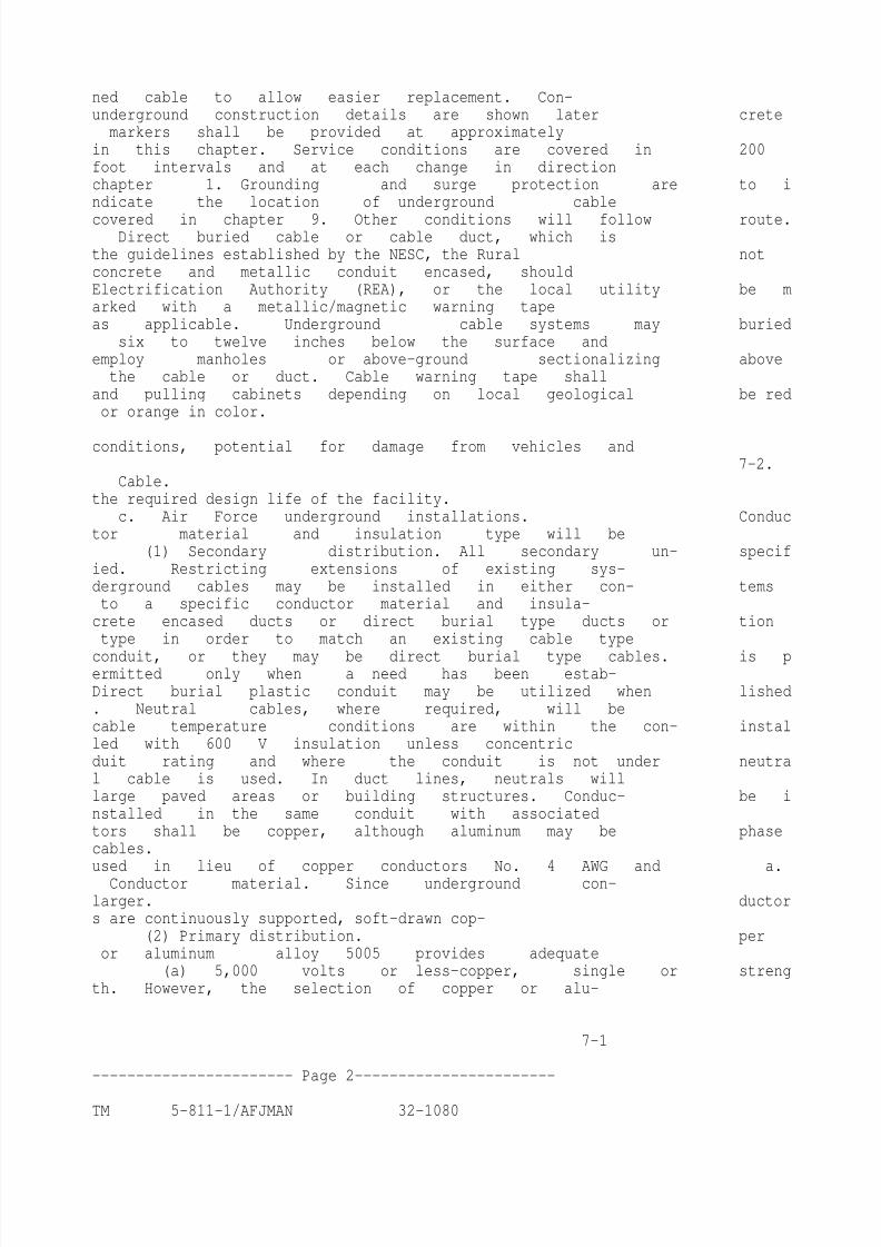
DUCT ENTRANCE
CABLE JOINT
REQUIREMENTS
Fireproof only medium-voltage circuits (over 600-volts).Fireproof cables their entire length within
the manhole and Into the duct entrance as indicated.
US Army Corps of Engineers
Table 7-1. Rated Conductor Temperatures.
7 - 3
----------------------- Page 4-----------------------
8/3/2019 Underground Distributed Line
http://slidepdf.com/reader/full/underground-distributed-line 6/17
TM 5-811-1/AFJMAN 32-1080
components for maintaining symmetrical stress ing.Whenever separable insulated connectors aredistribution, minimizing voltage gradients, and usedfor this application, they should be of the
maximizing environmental protection. loadbreak type. The preformed kit must be suit-
(1) Connectors. Connectors will be of the com- able for the cable insulation and correctly sized forpression type or the plug-in type. Mechanical the cable diameter. Separable insulated connectorsconnectors of the bolted or screw type or thermal willnot be used in manholes, except where neces-connectors of the soldered, brazed, or welded type sary for reasons of clearance at airfields. Separablewill be used only in special cases where the insulated connectors will not be used in direct
application so warrants. Compression connectors burialapplications.above 5 kV need to be of the tapered-end type, or(3) Choice. Any of the cable joints discussedhave semiconducting (semicon) tape or molded maybe permitted as a Contractors option, whoseconstruction to give the same effect and thus limit selection is made by balancing labor savingsstresses. against material costs. Disconnectable loadbreak
(2) Other necessary joint components. The separable connectors, which are the most expen-other necessary components are contained with the sive
type of cable joints, will be used only whereconnectors in kits to provide joints which range thedisconnect feature is necessary. Metallic-from the fully field-assembled type (taped) to those armored cable splices will be enclosed inkits with mostly factory-formed parts (preformed) compound-filled metal splice boxes. Splice andwhich require less installation labor. Factory pre- terminator kits will be selected as recommendedformed kits are preferred. The field-assembled kits by thecable manufacturer.will not be used unless the Contractor cannot(4) Dissimilar material. Both aluminum-to-locate the preformed kits, and the Contractor copperconductor and nonmetallic-jacketed to lead-employes a cable splicer approved by the Contract- covered cable connections are easily made whening Officer. connectors and splicing materials are correctly
(a) Conventional taped or resin system splice utilized and installed. While transitions from onekits. These kits cost the least for materials and are material to another will not be permitted whenused to make up a significant number of cable installing new lines, such transitions between
joints, but this type requires the most labor to existing and new work are acceptable for exten-install. Joints are longer and bulkier than other sions
8/3/2019 Underground Distributed Line
http://slidepdf.com/reader/full/underground-distributed-line 7/17
and additions.types. Quality is dependent upon the splicers skill e. High-voltage cable terminations. A device usedlevel, so joint workmanship can vary widely. Any forterminating alternating-current power cableskit selected must have splice tapes suitable for the having
extruded, solid, or laminated insulation
cable insulation. Refer to IEEE Std 141 for details whichis rated 2.5 kV and above is known as a
and specifications of cable joints. high-voltage cable termination.
(b) Heat-shrinkable splice kits. These kits(1) Provisions. Such terminations are coveredinclude factory preformed splices which are heat- by IEEE Std 48 which requires terminations to betreated in the field to fit the conductor. This type able to provide one or more of the following:is simpler to install than the conventional taped or(a) Electric stress control for the cable insu-
resin type, and provides a less bulky splice than lationshield terminus.any of the other types. A kit will fit a range of(b) Complete external leakage insulation be-cable sizes, but kits may not be available for other tweenthe cable conductors and ground.than solid dielectric single-conductor cables.
(c) A seal at the end of the cable against the(c) Separable insulated connectors. Such con- entran
ce of the external environment which alsonectors are fully factory preformed into the mini- maintains the pressure, if any, of the cable system.mum of parts necessary to adapt either the recep-
(2) Types. Termination types are defined bytacle and plug or the connector and splice body to IEEEStd 48 as Class 1, which provides all of thethe cable insulation, shielding, and jacket. Such above
three conditions (and includes potheads, ajoints cannot be used for laminated insulations, term
now rapidly becoming obsolete), Class 2but provide a waterproof and totally submersible whichprovides the first two conditions, and Class
joint for solid or extruded dielectric insulations. 3 which provides only the first condition. The firstThese joints are the quickest to install, but the two classes include both indoor and outdoor types,labor savings may be outweighed by the highest butClass 3 can only be used indoors. Protectioninitial cost. Greater reliability has been reported fromdirect exposure to solar radiation or precipi-by utility and industry records for these joints. tationis required for outdoor types.Connections do provide disconnectability for future(3) Requirements. Class 2 terminations withtaps or for cable sectionalizing during fault test- theirunsealed ends are subject to tracking when
7 - 4
----------------------- Page 5-----------------------
8/3/2019 Underground Distributed Line
http://slidepdf.com/reader/full/underground-distributed-line 8/17
TM 5-811-1/AFJMAN 32-1080
exposed to humidity changes occurring inside out- cable with a fireproofing tape, spraying the cabledoor equipment. Class 3 terminations, with their with a foreproofing coating, or installing fire stops
exposed length in addition to the exposed end, can in themanhole. Medium-voltage cables and con-
be more difficult to maintain plus more dangerous ductors in manholes that are taped or coated withto maintenance personnel. Since the use of the a fireproofing material will be taped or coated formore expensive Class 1 type causes an almost theirentire length on an individual cable basis.unnoticable overall cost increase in the provision Figure7-1 shows cable fireproofing details for a
of a medium-voltage cable installation, only Class taped installation. Polymeric elastomer tapes will
1 terminations will be used. Either taped or be used. Asbestos tapes are not permitted. Wherepreformed Class 1 terminations are acceptable. cableshave been lubricated to enhance pulling
Use of the next higher BIL rating in contaminated into ducts, the lubricant will be removed fromareas is not recommended, as it is preferable to cablesexposed in the manhole before fireproofing.have a cable failure at the termination rather g. Insulation tests. Cable testing will be speci-than within the cable length. fied to be performed and successfully completed for
f. Fireproofing. High current arcs can cause all med
ium-voltage cable installations. Cable test-heat or even flames which can destroy cables ing will include the testing of the adequacy of alladjacent to the arc. To limit damage, cables are cable splices and terminations, as applicable. Ca-often fireproofed in manholes and vaults. Fire- bles will be disconnected from equipment duringproofing should be limited to cables rated above the testing process. The first testing of new cables600 V. Fireproofing methods include wrapping the is performed by the cable manufacturer at the
Figure 7-1. Fireproofing of Insulated Cables.
7 - 5
----------------------- Page 6-----------------------
TM 5-811-1/AFJMAN 32-1080
factory, and is performed in accordance with indus- a.Construction.try standards. The designer will specify the field (
1) Wall thickness. Nonmetallic ducts are man-tests in accordance IEEE Std 400. Unless the cable ufactured with thin-wall (type EB) and thick-wall
8/3/2019 Underground Distributed Line
http://slidepdf.com/reader/full/underground-distributed-line 9/17
accessory manufacturers indicate higher voltages (typeDB) thicknesses. The thin-wall type is de-
are acceptable, test voltages will not exceed the signedto be used with an added concrete encase-
recommendations of IEEE Std 404 for cable joints ment.The thick-wall type is used without encase-and IEEE Std 48 for cable terminations. Table 7-2 ment in
concrete; this type of duct is installed withcompares the recommendations of various stan- an earth fill separating the ducts in a bank, exceptdards regarding test voltages for insulation, termi- that under areas used for vehicular traffic concretenations, and joints. Test voltages for 28 kV and 35 encasement is necessary. Guidelines indicatingkV cable insulation should be in accordance with where
concrete encasement is necessary are pro-the AEIC standards since ICEA/NEMA standards vided in chapter 5.do not cover 133 percent insulation for these two (
2) Shape. Most ducts have round exteriorsvoltage classes. Tests for cables 600 volts and witha round bore; however, octagonal and squarebelow will be specified in accordance with IEEE exteriors are available, as are square bores.Std 422. Squareor octagonal exteriors may make stacking
easierin some cases, but round bores are prefera-
7-3. Duct lines.ble for
cable pulling.Excluding Alaska and other permafrost locations, (
3) Number. Ducts are available in a singleduct lines will be installed in accordance with the raceway
configuration. Although some ducts areNESC regarding the frost line (i.e., below frost available in multiple duct units with from two tolines or restrained with backfill, concrete encase- nine raceways in each length, this type will not bement, bracing, or other means to maintain its used for electric power cables.design position under stress of installation proce- b.Systems. For new projects, duct lines will bedures, cable pulling operations, settling, or frost provided at the same time for both electric poweruplift). For permafrost locations, designs will incor- andcommunication circuits. See TM 5-811-9 forporate duct line installation methods which are communications systems requirements. Communi-standard for the base, post, or local utility. In clay cation
cables will be completely isolated fromsoil, not less than a three-inch layer of sand will electric power cables in accordance with ANSI C2,cover the bottom of the duct trench before ducts by using separate conduits and access points, suchare placed. Ducts will be covered with not less as manholes. Separate electric and communication
than a six-inch layer of sand after they are placed. conduits may be installed in the same duct bank,Metallic conduit will not be used when concrete however
8/3/2019 Underground Distributed Line
http://slidepdf.com/reader/full/underground-distributed-line 10/17
. For economy and space conservation,encasement is provided. When tying into an exist- electric power and communication ducts may being asbestos composite duct bank, proper environ- installed in the same trench and manholes may bemental protocol will be followed. The designer will adjacent, when such arrangements suit the com-
provide terrain profiles for all duct systems utiliz- munication circuit requirements of the appropriateing manholes. Systems utilizing above ground agency.
Power and communication cable separa-sectionalizing and pulling cabinets need profiles tionwill be in accordance with ANSI C2. Fiberonly in hilly or congested areas. opticcable (and duct) spacing from power cable
willbe the same as for conventional cable and
Table 7-2. Comparison of DC Test Voltages (kV) ductbecause of the continued use of hybrid sys-
tems,and to provide an increased margin ofJoints
Cable on protection for the fiber optic cable.Rated E x t r u d e d c.Sizes. The nominal diameter of raceways forVoltage 133 Percent Termina- Dielectric medium-voltage, communication, and other cables(kV) Insulation tions Cable in ducts between manholes will be four inches,Phase NEMA AEIC IEEE IEEE withlarger ducts provided where 15 kV cables
to W C 7 CS5 No. 48 No. 404 largerthan No. 4/0 AWG are to be installed. The
Phase W C 8 CS6 communication service duct to any building will
2.5 25 - 40 -not b
e less than three inches in diameter. Low-5.0 25 - 50 258.7 35 - 65 35 voltagepower ducts supplying building services15 65 - 75 55 will be
sized in accordance with the NEC. Exterior25 100 - 105 75 loads
supplied from a building such as multiple28 - 125 115 85 lightin
g, control, or motor loads will be served34.5 - 155 140 100
withnot less than l-inch ducts. In general, sizes
7 - 6
----------------------- Page 7-----------------------
TM 5-811-1/AFJMAN 32-1080
of underground raceways installed should be the ple

8/3/2019 Underground Distributed Line
http://slidepdf.com/reader/full/underground-distributed-line 11/17
tely below-grade structures. In addition tonominal 4-inch, 3-inch, 2-inch, or 1-inch size, markers, 3-inch wide 5-mil brightly colored plas-except where large numbers of secondary ducts tic
tape placed approximately 12 inches belowmake this uneconomical, such as on tank farms. finished grade may be used.
d. Spare capacity. A sufficient number of spareducts will be provided in duct systems between 7-4. Manholes, Handholes, and Pullboxes.
manholes to provide for at least a 25 percent Intraffic areas, design will be for a H20 wheel
increase in the number of cables. The number of loading as defined by AASHTO HB-13.spare ducts will be increased as required for futurea. Manholes. Manholes will normally be locatedservice to planned expansion. Such spare provi- atstreet intersections and will be spaced otherwise
sions do not apply to building service ducts, unless tomeet facility needs; to conform to the facilitythere is a definite planned expansion or a planned master plan; or as required by the cable pullingincrease in reliability requires provision for dupli- calculations.cate feeders. Spare ducts should be plugged to
(1) Criteria for construction. Manholes will notprevent entry of debris and rodents. beless than six feet in depth, by six feet in length,
e. Installation. Installation requirements for byfour feet in width with an access opening to theconcrete-encased duct lines will meet requirements sur
face above (outer air) of not less than 30 inchesof ANSI C2. Figure 7-2 shows typical contigura- in
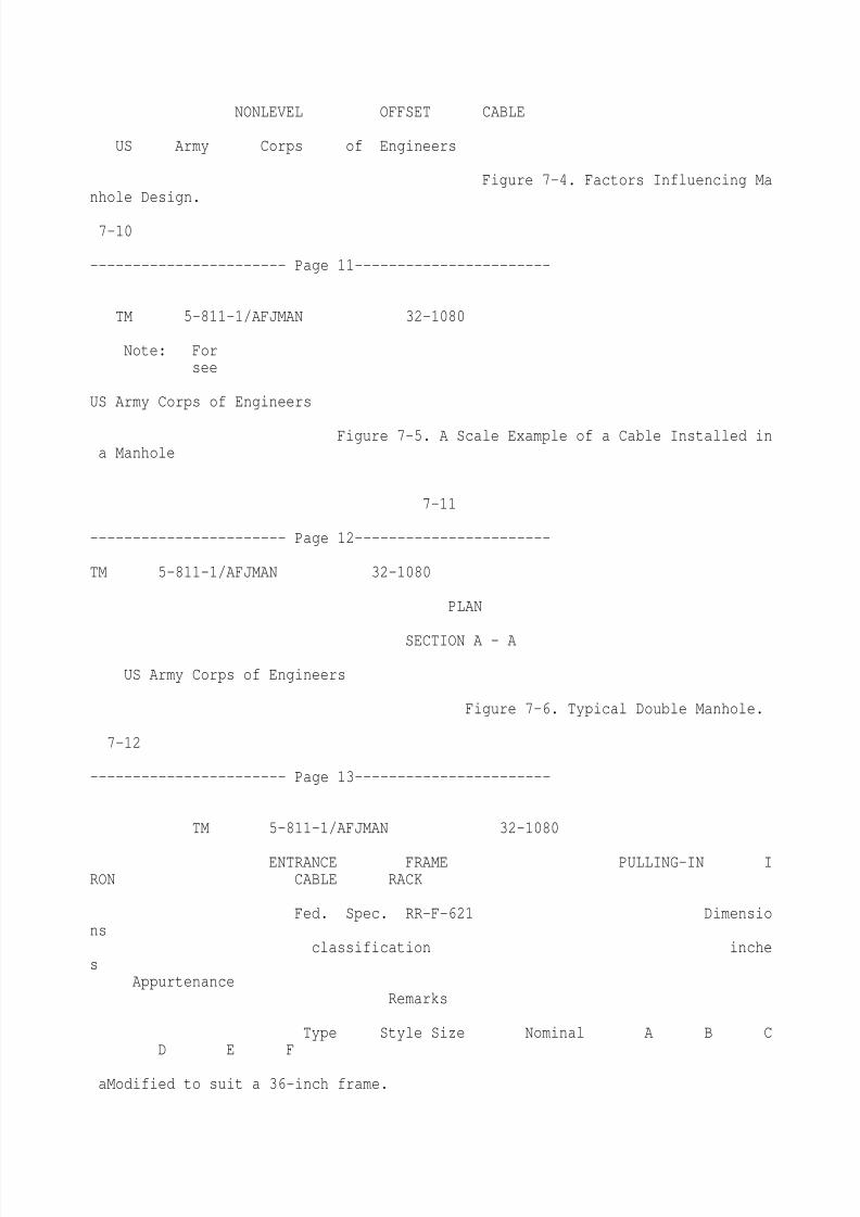
diameter. Manholes will provide a minimumtions, however, spacing and arrangement will be wall space of six feet on all sides where splices willadapted to ensure adequate conductor ampacities beracked. Duct entrances into the manhole can bein accordance with the NEC and IEEE/ICEA located near one end of long walls so that sharppublications. Additional duct configurations are bends of cables at the duct mouth are avoided, ordepicted in the NEC. Figure 7-3 indicates drain- else sufficient space will be provided for a reverseage requirements for underground ducts. bend before the cable straightens out on the wall
(1) Maximum number of conduits in a duct onwhich the cable is racked. Manhole elevations
run. Electric power cables generate heat depen- andelevations of duct lines entering manholes willdent upon the cable loading and resistance. Dissi- be
shown. For nonmetallic-jacketed cables, thepation of this heat is no problem because of minimum bending radius will be 12 times thediversity of cable loading, as previously noted. overall cable diameter. Metallic-jacketed cable
More than eight ducts entering at any one point in bends will be in accordance with ICEA/NEMAa manhole provide a cable congestion which makes req
8/3/2019 Underground Distributed Line
http://slidepdf.com/reader/full/underground-distributed-line 12/17
uirements or 12 times the overall cable diame-maintenance time-consuming and costly. Where ter, whichever is greater. Figure 7-4 shows detailsthe use of more than eight ducts in a single run is offactors which affect lengths of manholes. A scalenecessary, the minimum manhole size required, as example of a specific cable size installed in a
noted later, will be increased. More than two duct manhole is shown on figure 7-5.entrances may require larger manhole sizes.
(2) Types of manholes. A combination electric(2) Configurations. Arrangements for electric pow
er and communications manhole suitable for(E) and communication (C) ducts are given below: use
with most electric power and communication4E or 4C . . . . . . . . . . . 2 ducts wide by 2 deep
duct arrangements is shown on figure 7-6. Other4E and 4C . . . . . . . . . . . . 4 ducts
wide by 2 deep arrangements are acceptable, but minimum inside
6E or 6C . . . . . . . . . . . 3 ducts wide by 2 deep
dimensions and reinforcing will match require-
6E and 6C . . . . . . . 6 ducts wide by 2 deep(3) Miscellaneous. men
ts shown on figure 7-6. Generally, manhole(a) Jacking. Where ducts are jacked under dra
wings indicate the requirements for a cast-in-existing pavement or used for exposed installa- place concrete manhole. Precast manholes may betions, rigid steel conduit will be installed because spe
cified as a Contractors option, when they pro-of its strength. To protect the corrosion-resistant vide the same inside dimensions, strength, andconduit coating, predrilling or installing conduit sealed joints comparable to the monolithic con-inside a larger iron pipe sleeve (jack-and-sleeve) is struction of case-in-place manholes. Prefabricated
vaults of other than concrete construction will berequired when conduits are jacked. For crossingsof existing railroads and airfield pavements restricted to direct-burial cable systems.greater than 50 feet in length, the predrilling
(3) Prohibited devices. Electrical equipmentsuc
h as transformers or switches should not bemethod or the jack-and-sleeve method will be used.
(b) Duct line markers. Duct line markers installed in manholes or underground vaults, ex-will be provided only for duct line stubouts or for cept in manholes adjacent to airfields where suchother ducts whose locations are indeterminate installations may be necessary to meet airfieldbecause of duct curvature or terminations at com- clearance requirements, or as specifically required
7 - 7
8/3/2019 Underground Distributed Line
http://slidepdf.com/reader/full/underground-distributed-line 13/17
----------------------- Page 8-----------------------
TM 5-811-1/AFJMAN 32-1080
SINGLE DUCT ELECTRICOR COMMUNICATION
DUCT BANK
ELECTRIC AND COMMUNICATION
DUCT BANK
R E I N F O R C E D D UC T B A N K
NOTES:A. ELECTRICAL SUPPLY DUCT:
ARRANGEMENTS. SIZES. AND DIMENSIONS SHOWN ABOVE WILL CONFORM TO THE REQUIREMENTSOF NFPA 70.
B. ENCASEMENT DIMENSIONS ARE TO BE DETERMINED BASED ON LOCATION. BURIAL DEPTHS.
AND STRENGTH REQUIREMENTS.
C. COMMUNICATIONS SUPPLY DUCT:SEPARATIONS ARE DEPENDENT ON COMMERCIALLY
AVAILABLE DUCT SPACERS FOR THERESPECTIVE CONDUIT SIZE.
D. ANSI C2 MINUIMUM SEPARATION FOR SUPPLY-COMMUNICATION IS 3 INCHES CONCRETE.
Figure 7-2. Concrete Encased DuctDetails
7 - 8
----------------------- Page 9-----------------------
TM 5-811-1/AFJMAN 32-1080
by the Using Agency, and then equipment will be frommanhole and ductline systems or other
of the type which can be submersed. Where the sourcesfor low-voltage power and communication
water table is high enough to flood manholes, supplyto building services. A handhole suitable
water will be removed by portable pumps operated for most electric power or communication usage ison a regular schedule. Permanently connected shown
on figure 7-8. At least four racks will besump pumps will not be installed, except in special installed. Where more than two splices occur, a
instances. Permanent ladders will not be installed; manholemay be more appropriate.portable ladders will be used when required. (
8/3/2019 Underground Distributed Line
http://slidepdf.com/reader/full/underground-distributed-line 14/17
2) Pullboxes. Pullboxes are used for electric(4) Manhole appurtenances. Ground rods will circuit
s supplying low-voltage electric loads whichbe installed in one corner of each electric manhole require
conductors no larger than No. 1/0 AWGfor metallic shield or sheath grounding to reduce and no more than one 2-inch conduit entrance at
induced potential gradients. Dangerous gradients eachside. Where larger conduits are installed,
are not induced by communication circuits, so rods handholes or manholes will be used. Becausewill not be installed in communication manholes. pullbox
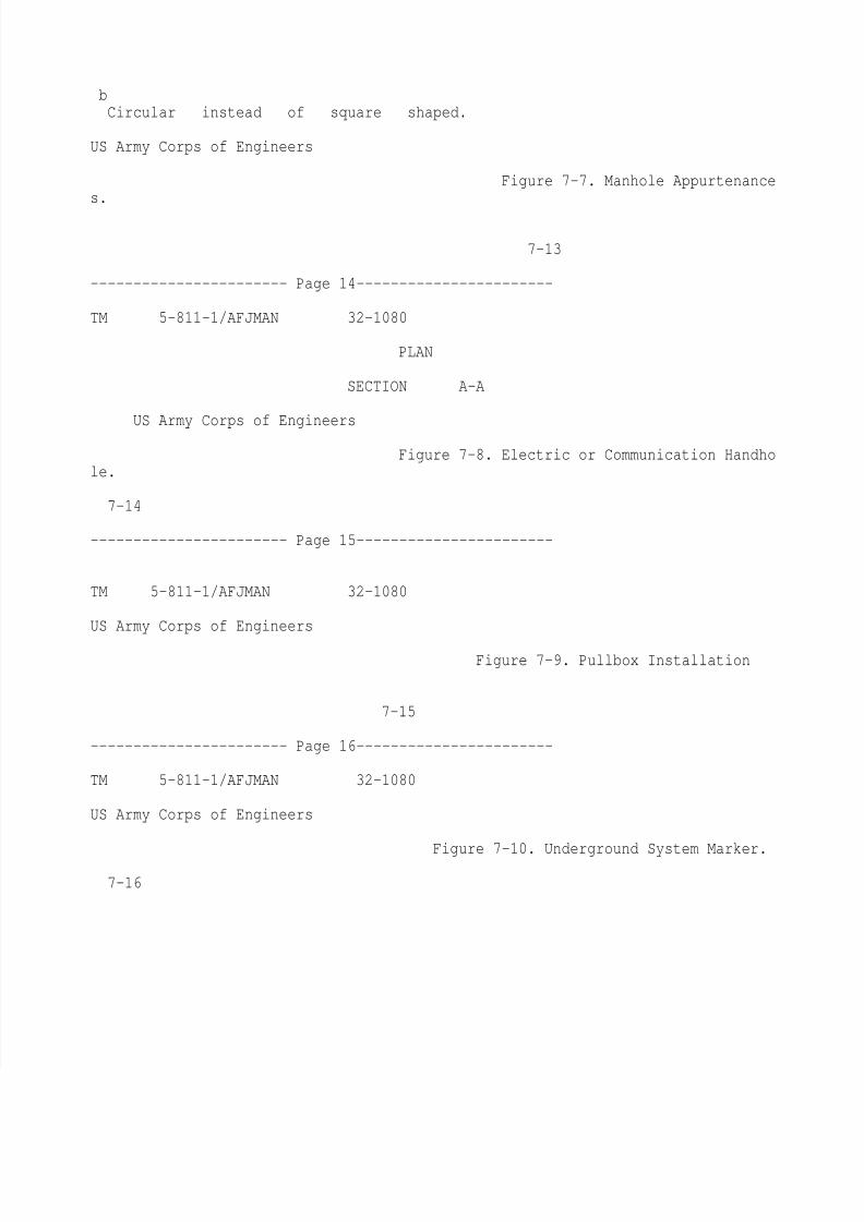
depths are less than two feet, conduitsOther manhole appurtenances are shown on figure mustalways slope up into the pullbox. Pullboxes7-7. Square covers will not be used because of the are also suitable for fire alarm, public address, anddanger of the cover slipping through the opening. control
circuits. Pullboxes will not be used for
The traffic cover shown on figure 7-7 is suitable telephone circuits without the approval of thefor AASHTO H20 wheel loadings. Pulling-in irons appropriate communication agency. Figure 7-9will be provided opposite each duct entrance or shows
standard sizes of pullboxes used for low-where there are provisions for future duct en- voltage
installations. Pullboxes will not be used intrances. Sufficient cable racks will be installed to areassubject to vehicular traffic. In such areas,properly support cables on both sides of any cable handholes will be installed. The use of a pullbox atsplice and elsewhere as needed. Rack horizontal the b
ase of a lighting pole is unnecessary in mostspacing will be 3 feet to 4-½ feet for electric cases.power cables dependent upon the nature of the c. Manholes at Air Force installations.cable bends. At least two racks will be located on
(1) General requirements. Manholes shall beeach wall, except, racks will not be more than 30 adequately sized, shall comply with applicableinches apart horizontally. requirements of OSHA, and AASHTO, and may be
(5) Communication manholes are to be de- precastor cast-in-place. Openings should be round
signed in accordance with Army Field Manual and not less than 32 inches in diameter.11-486-5, Telecommunications Engineering Out- (2) Manholes for aircraft operating and park-side Plant Telephones, paragraphs 7-17 to 7-30. ing aprons. Electrical manholes in aprons shall be
b. Other Types of Cable Access Points. Where avoided. Cables shall be installed beyond thesplicing or pulling of cables requires an access periphery of aprons. Electrical manholes shallpoint, but the volume provided by a manhole is maintain a distance of 50 feet from the edge of
unnecessary, handholes or pullboxes will be pro- pavingand 50 feet from any hydrant lateral
vided as appropriate. contro
8/3/2019 Underground Distributed Line
http://slidepdf.com/reader/full/underground-distributed-line 15/17
l pit and 200 feet from a fueling point.(1) Handholes. Handholes are used on laterals
DUCT LINE ELEVATION
US Army Corps of Engineers
Figure 7-3. Duct Line Drainage.
7-9
----------------------- Page 10-----------------------
TM 5-811-1/AFJMAN 32-1080
7-5. Direct-Burial Cable Installations. rail
roads, cables will be installed in concrete-Cables will be installed not less than the mini- encased ducts for protection. Under railroads andmum depth required by the NEC or, excluding airfield crossings, concrete-encased ducts must beAlaska and other permafrost areas, as necessary to steel-reinforced.be below the frost line, whichever is greater. b. Markers. Cable markers will be located near
theends of cable runs, at each cable joint or splice,
a. Protection. In some locations, nonmetallic-at
approximately every 500 feet along cable runs,jackets may not provide sufficient cable protection.
andat changes in direction of cable runs. In
Metal armor provides protection from rodents. addition to markers, a 3-inch wide 5-mil, brightlyDirect-burial cable with concentric neutral, in- colored plastic tape placed approximately 12stalled in ducts, will incorporate the same overall inches below finished grade will be used. Wherejacket as that specified for direct burial. Where cable is used for lighting circuits and the lightingburied cable warning is required by the using poles effectively provide indication of directionagency, tape manufactured for this purpose will be changes, markers are not required. Markers willprovided. Where installed under traffic areas or be similar to the one shown on figure 7-10.
PLAN ELEVATIONPLAN ELEVATION
LEVEL OFFSET CABLELEVEL CABLE TURN
1
I
PLAN ELEVATION
8/3/2019 Underground Distributed Line
http://slidepdf.com/reader/full/underground-distributed-line 16/17
NONLEVEL OFFSET CABLE
US Army Corps of Engineers
Figure 7-4. Factors Influencing Manhole Design.
7-10
----------------------- Page 11-----------------------
TM 5-811-1/AFJMAN 32-1080
Note: Forsee
US Army Corps of Engineers
Figure 7-5. A Scale Example of a Cable Installed ina Manhole
7-11
----------------------- Page 12-----------------------
TM 5-811-1/AFJMAN 32-1080
PLAN
SECTION A - A
US Army Corps of Engineers
Figure 7-6. Typical Double Manhole.
7-12
----------------------- Page 13-----------------------
TM 5-811-1/AFJMAN 32-1080
ENTRANCE FRAME PULLING-IN IRON CABLE RACK
Fed. Spec. RR-F-621 Dimensions
classification inches
AppurtenanceRemarks
Type Style Size Nominal A B CD E F
aModified to suit a 36-inch frame.
8/3/2019 Underground Distributed Line
http://slidepdf.com/reader/full/underground-distributed-line 17/17
bCircular instead of square shaped.
US Army Corps of Engineers
Figure 7-7. Manhole Appurtenances.
7-13
----------------------- Page 14-----------------------
TM 5-811-1/AFJMAN 32-1080
PLAN
SECTION A-A
US Army Corps of Engineers
Figure 7-8. Electric or Communication Handhole.
7-14
----------------------- Page 15-----------------------
TM 5-811-1/AFJMAN 32-1080
US Army Corps of Engineers
Figure 7-9. Pullbox Installation
7-15
----------------------- Page 16-----------------------
TM 5-811-1/AFJMAN 32-1080
US Army Corps of Engineers
Figure 7-10. Underground System Marker.
7-16