Embed Size (px)
Citation preview
The Application of Distributed Optical
Sensing for Monitoring Support in
Underground Excavations
Bradley J. Forbes
MASc. thesis submitted to the department of
Geological Sciences and Geological Engineering
Co-supervisors: Dr. Nicholas Vlachopoulos & Dr. Mark S. Diederichs
Presentation Overview
Introduction:
- Motivation for research
Background:
- Underground support
- Conventional monitoring
- Optical strain sensing
Development of the optical technique
Verification and demonstration through a laboratory testing scheme
Major findings and conclusions of research

Motivation for Research
Pasar Rakyat MRT Station, Kuala Lampur, Malaysia Long-wall mining method, Colorado, U.S.
Larger and longer tunnelling projects to accommodate resource and public
transportation
Deeper underground mining and nuclear waste repositories
courtesy of coaleducation.orgcourtesy of thestar.com: EPA/Ahmad Yusni
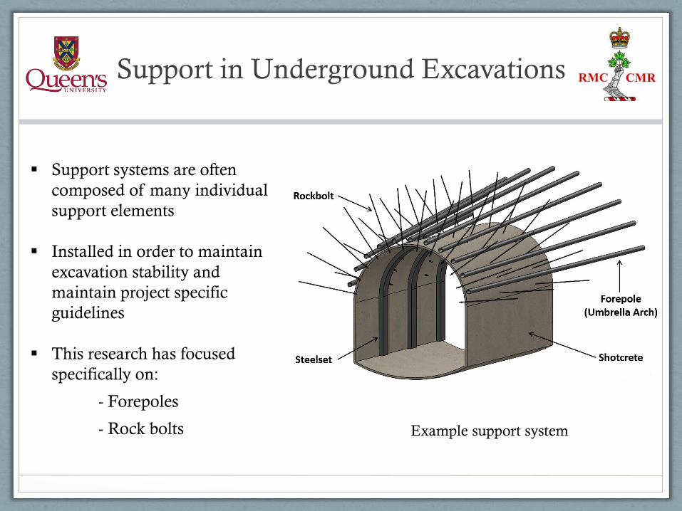
Support in Underground Excavations
Support systems are often
composed of many individual
support elements
Installed in order to maintain
excavation stability and
maintain project specific
guidelines
This research has focused
specifically on:
- Forepoles
- Rock bolts Example support system
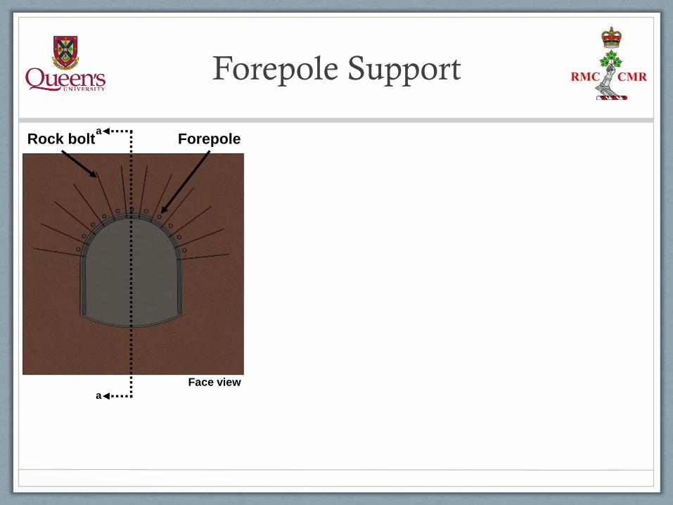
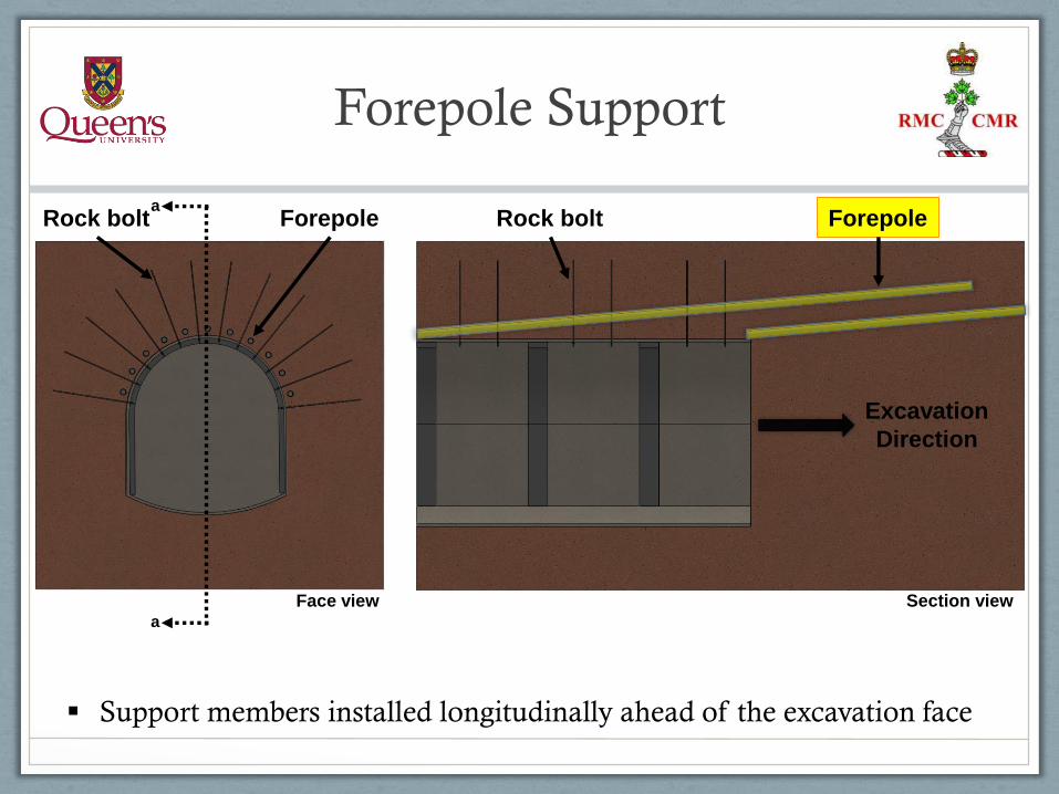
Forepole Support
ForepoleRock bolt
a
a
Face view
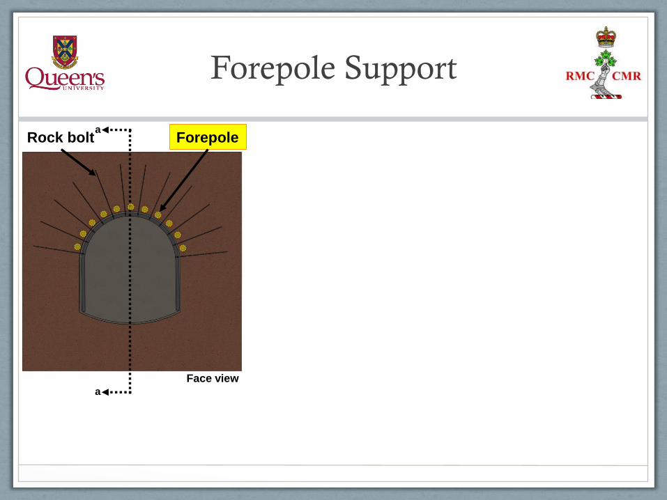
Forepole Support
ForepoleRock bolt
a
a
Face view
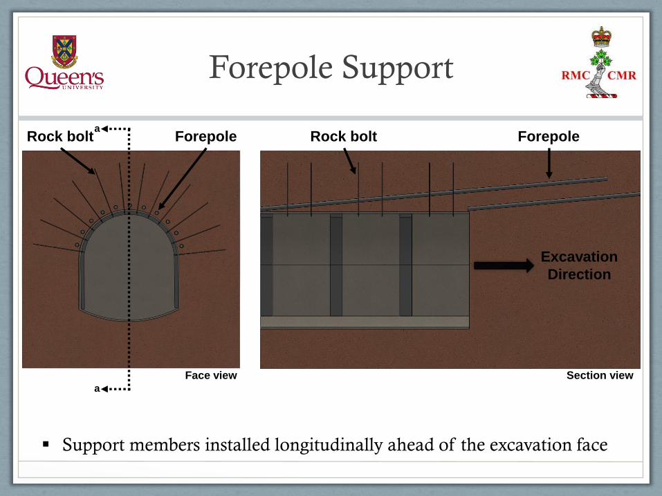
Forepole Support
ForepoleForepoleRock bolt Rock bolt
Excavation
Direction
a
a
Face view Section view
Support members installed longitudinally ahead of the excavation face
Forepole Support
ForepoleForepoleRock bolt Rock bolt
Excavation
Direction
a
a
Support members installed longitudinally ahead of the excavation face
Face view Section view
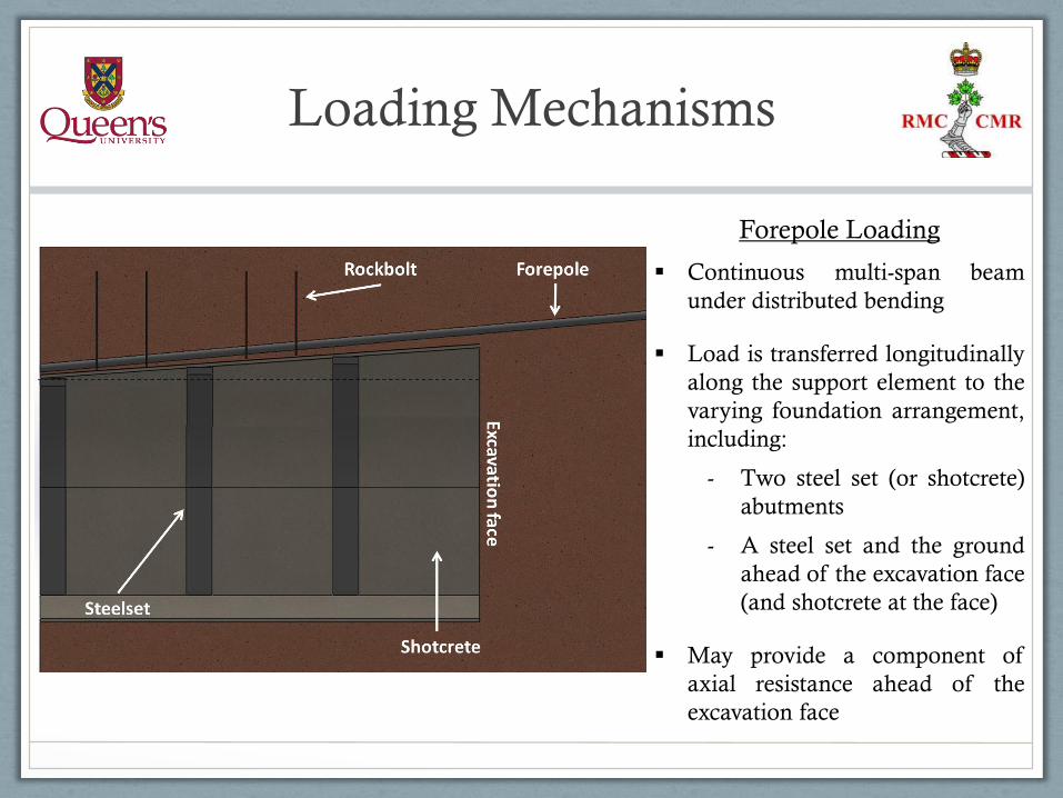
Loading Mechanisms
Forepole Loading
Continuous multi-span beam
under distributed bending
Load is transferred longitudinally
along the support element to the
varying foundation arrangement,
including:
- Two steel set (or shotcrete)
abutments
- A steel set and the ground
ahead of the excavation face
(and shotcrete at the face)
May provide a component of
axial resistance ahead of the
excavation face
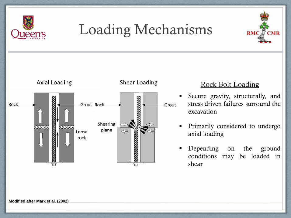
Loading Mechanisms
Modified after Mark et al. (2002)
Rock Bolt Loading
Secure gravity, structurally, and
stress driven failures surround the
excavation
Primarily considered to undergo
axial loading
Depending on the ground
conditions may be loaded in
shear
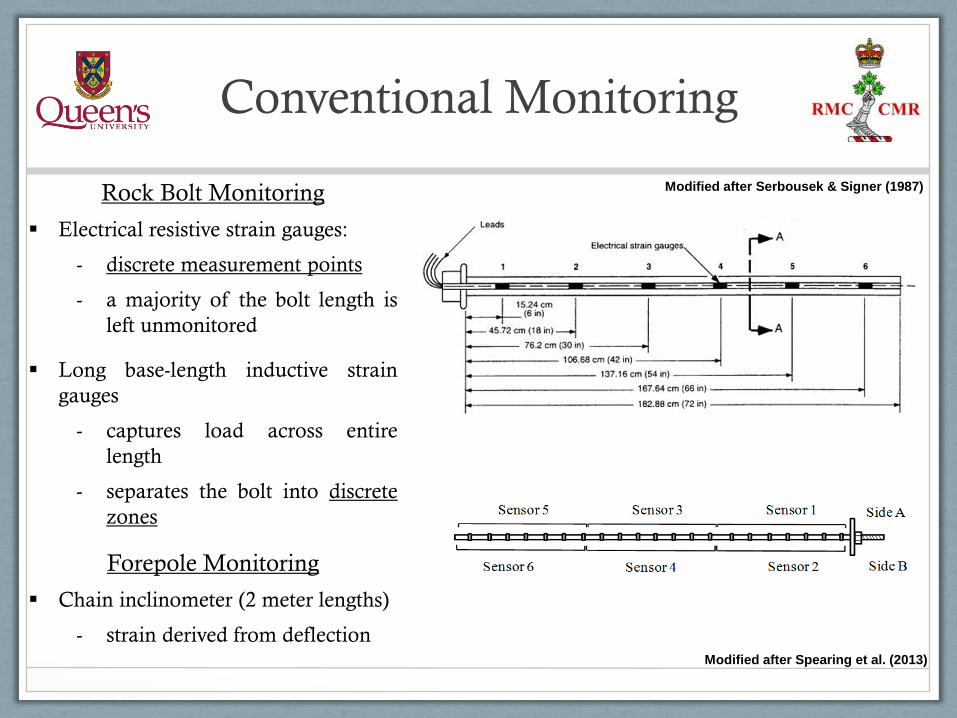
Conventional Monitoring
Modified after Spearing et al. (2013)
Rock Bolt Monitoring
Electrical resistive strain gauges:
- discrete measurement points
- a majority of the bolt length is
left unmonitored
Long base-length inductive strain
gauges
- captures load across entire
length
- separates the bolt into discrete
zones
Forepole Monitoring
Chain inclinometer (2 meter lengths)
- strain derived from deflection
Modified after Serbousek & Signer (1987)
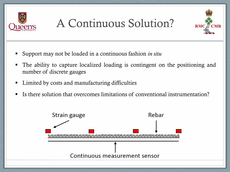
A Continuous Solution?
Support may not be loaded in a continuous fashion in situ
The ability to capture localized loading is contingent on the positioning and
number of discrete gauges
Limited by costs and manufacturing difficulties
Is there solution that overcomes limitations of conventional instrumentation?
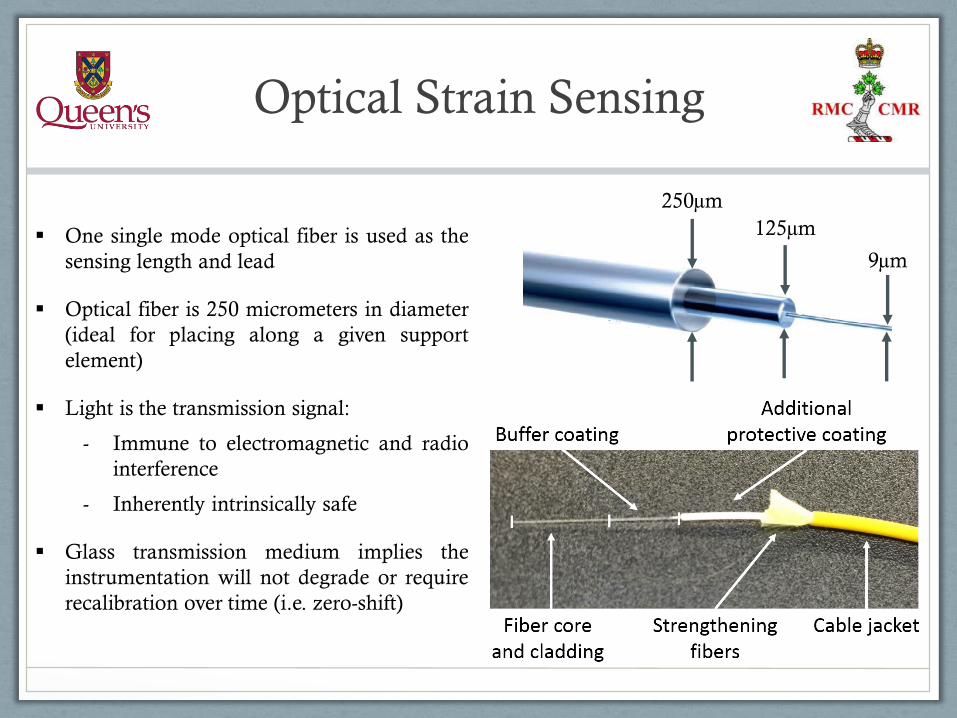
Optical Strain Sensing
One single mode optical fiber is used as the
sensing length and lead
Optical fiber is 250 micrometers in diameter
(ideal for placing along a given support
element)
Light is the transmission signal:
- Immune to electromagnetic and radio
interference
- Inherently intrinsically safe
Glass transmission medium implies the
instrumentation will not degrade or require
recalibration over time (i.e. zero-shift)
250µm
125µm
9µm

Optical Strain Sensing
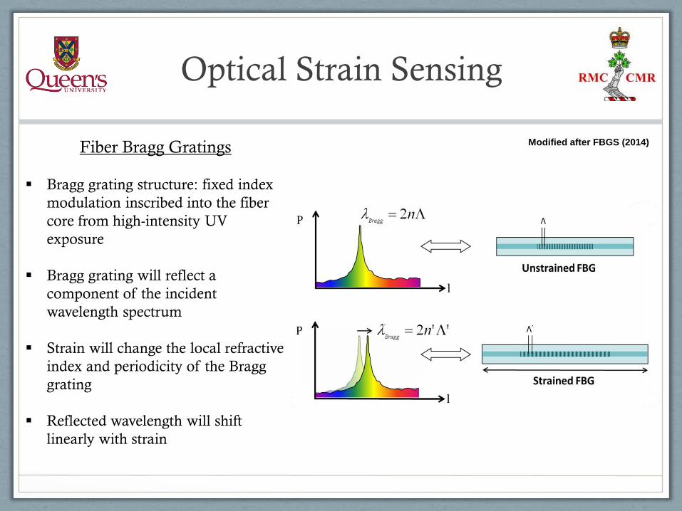
Fiber Bragg Gratings
Bragg grating structure: fixed index
modulation inscribed into the fiber
core from high-intensity UV
exposure
Bragg grating will reflect a
component of the incident
wavelength spectrum
Strain will change the local refractive
index and periodicity of the Bragg
grating
Reflected wavelength will shift
linearly with strain
Modified after FBGS (2014)
Optical Strain Sensing
Modified after FBGS (2014)Fiber Bragg Gratings
Bragg grating structure: fixed index
modulation inscribed into the fiber
core from high-intensity UV
exposure
Bragg grating will reflect a
component of the incident
wavelength spectrum
Strain will change the local refractive
index and periodicity of the Bragg
grating
Reflected wavelength will shift
linearly with strain
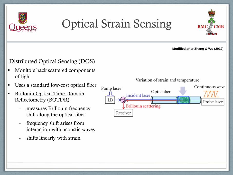
Optical Strain Sensing
Distributed Optical Sensing (DOS)
Monitors back scattered components
of light
Uses a standard low-cost optical fiber
Brillouin Optical Time Domain
Reflectometry (BOTDR):
- measures Brillouin frequency
shift along the optical fiber
- frequency shift arises from
interaction with acoustic waves
- shifts linearly with strain
Modified after Zhang & Wu (2012)

Optical Strain Sensing
Distributed Optical Sensing (DOS)
Monitors back scattered components
of light
Uses a standard low-cost optical fiber
Rayleigh Optical Frequency Domain
Reflectometry (ROFDR):
- measures Rayleigh scatter
- scatter arises from random
fluctuations in the refractive
index
- strain alters the local refractive
index along the fiber
Modified after Fuji Technical Research Inc.
Optical Strain Sensing
Modified after Fuji Technical Research Inc.
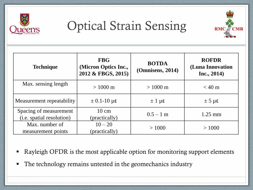
Technique
FBG
(Micron Optics Inc.,
2012 & FBGS, 2015)
BOTDA
(Omnisens, 2014)
ROFDR
(Luna Innovation
Inc., 2014)
Max. sensing length> 1000 m > 1000 m < 40 m
Measurement repeatability ± 0.1-10 µε ± 1 µε ± 5 µε
Spacing of measurement
(i.e. spatial resolution)
10 cm
(practically)0.5 – 1 m 1.25 mm
Max. number of
measurement points
10 – 20
(practically)> 1000 > 1000
Rayleigh OFDR is the most applicable option for monitoring support elements
The technology remains untested in the geomechanics industry
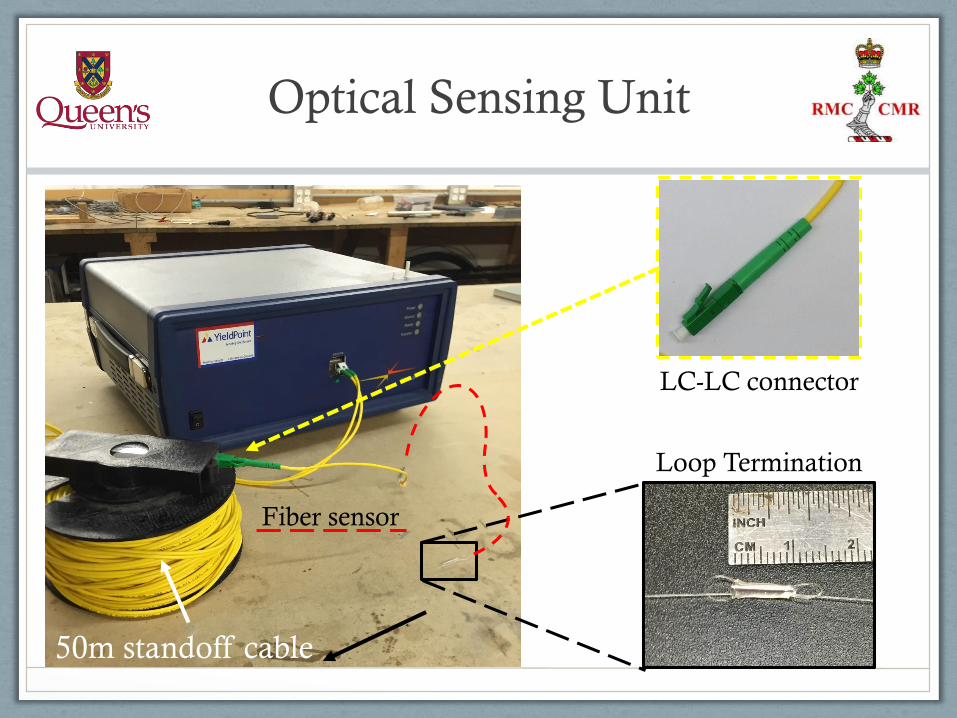
Optical Sensing Unit
Loop Termination
50m standoff cable
Fiber sensor
LC-LC connector
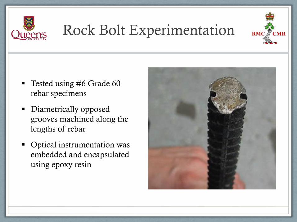
Tested using #6 Grade 60
rebar specimens
Diametrically opposed
grooves machined along the
lengths of rebar
Optical instrumentation was
embedded and encapsulated
using epoxy resin
Rock Bolt Experimentation
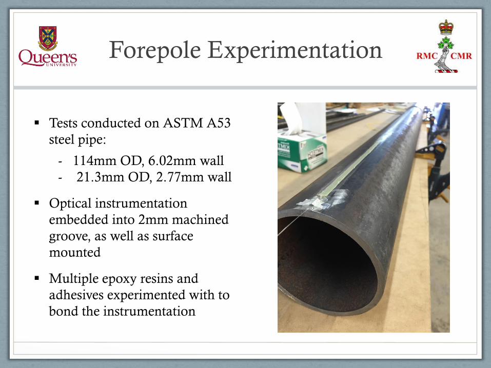
Tests conducted on ASTM A53
steel pipe:
- 114mm OD, 6.02mm wall
- 21.3mm OD, 2.77mm wall
Optical instrumentation
embedded into 2mm machined
groove, as well as surface
mounted
Multiple epoxy resins and
adhesives experimented with to
bond the instrumentation
Forepole Experimentation
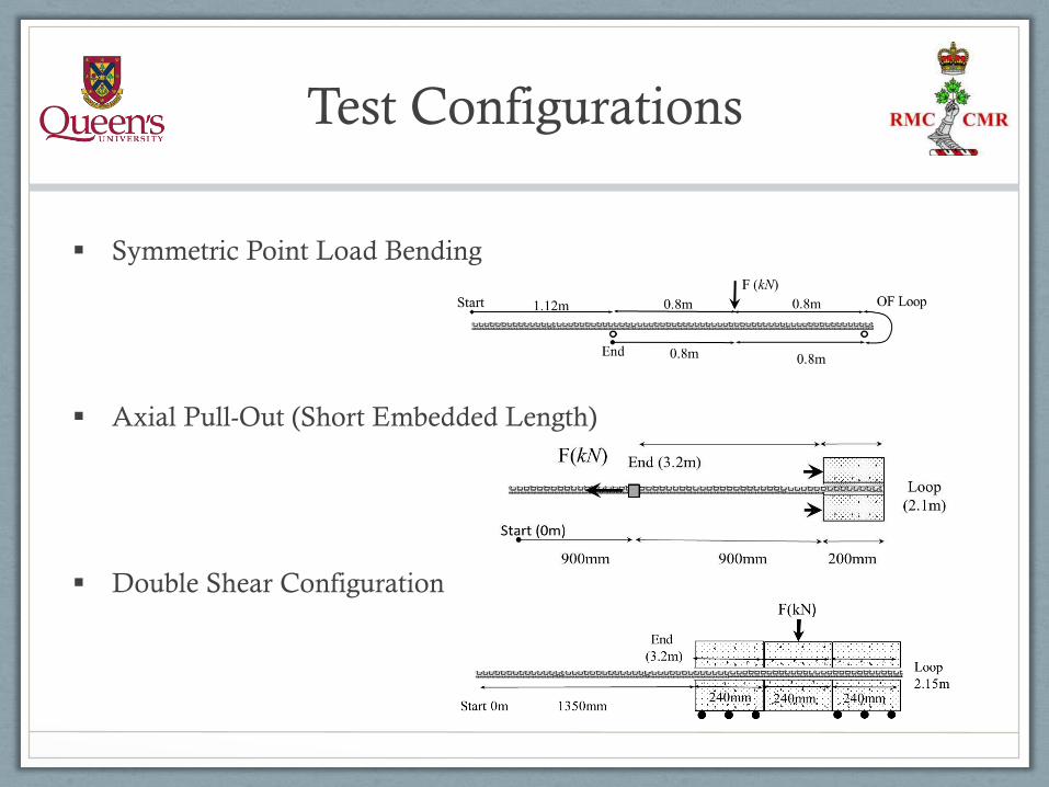
Symmetric Point Load Bending
Axial Pull-Out (Short Embedded Length)
Double Shear Configuration
Test Configurations
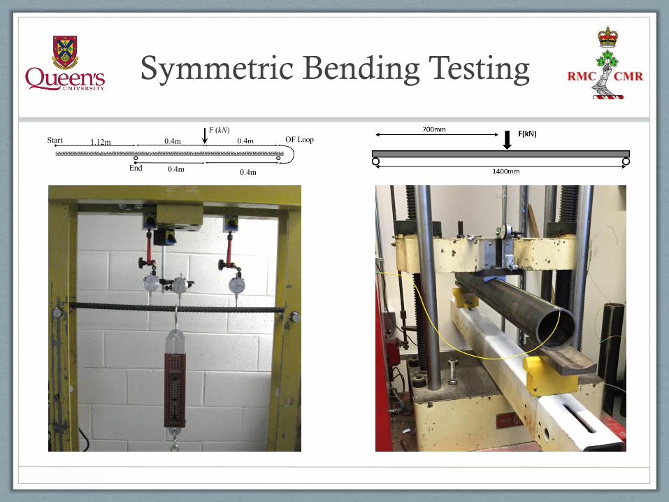
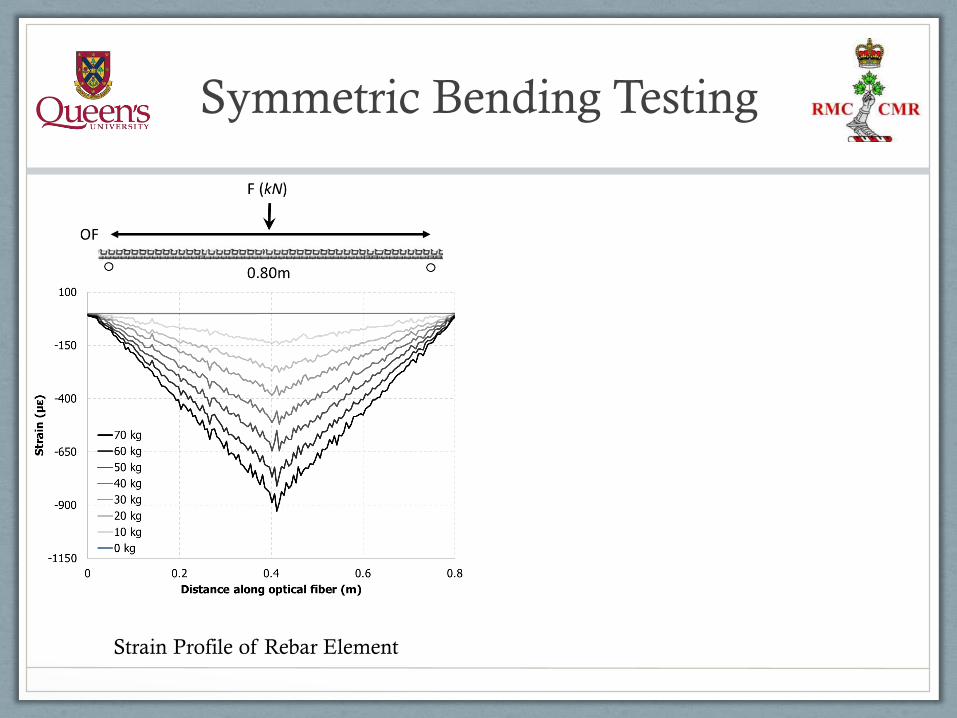
Symmetric Bending Testing

Symmetric Bending Testing
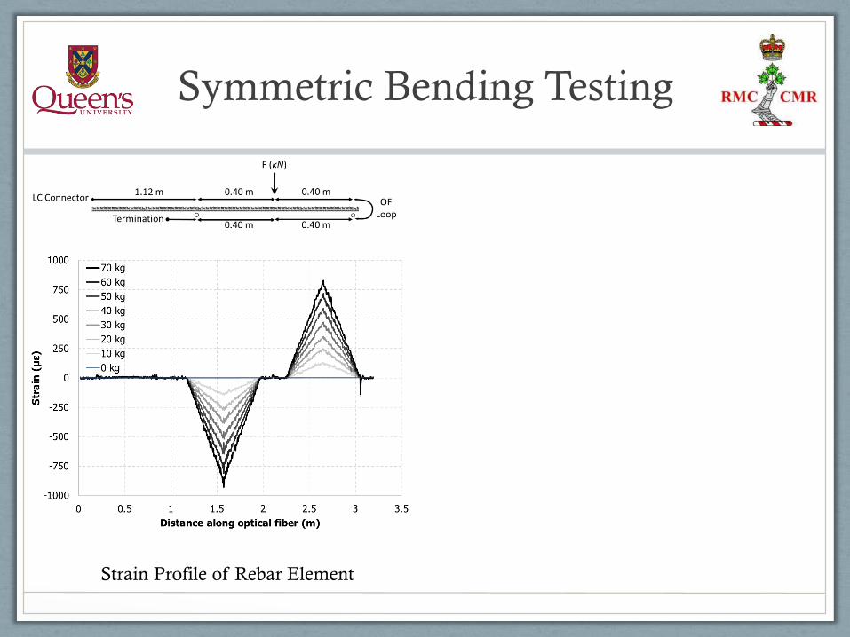
Symmetric Bending Testing
Strain Profile of Rebar Element
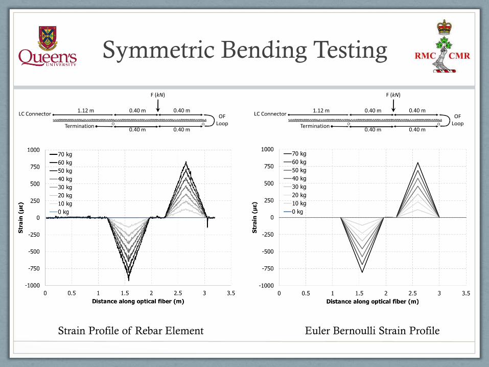
Symmetric Bending Testing
Strain Profile of Rebar Element Euler Bernoulli Strain Profile
Symmetric Bending Testing
Strain Profile of Rebar Element
Symmetric Bending Testing
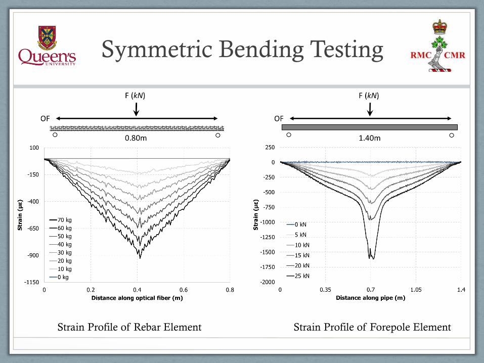
Strain Profile of Rebar Element Strain Profile of Forepole Element

Symmetric Bending Testing
Strain Profile of Rebar Element Strain Profile of Forepole Element
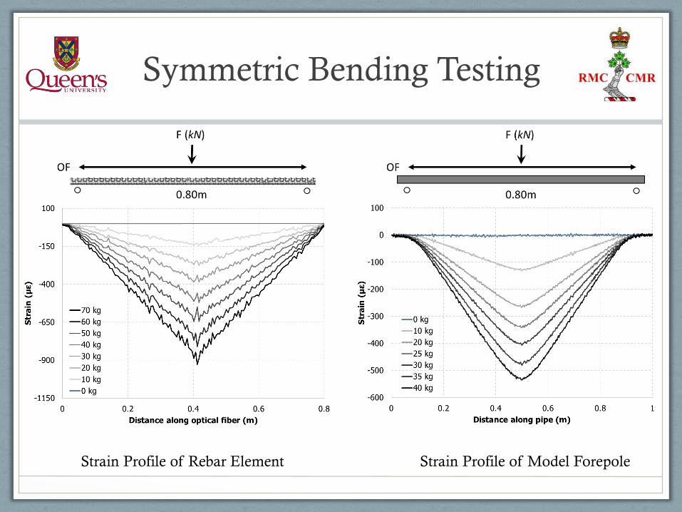
Symmetric Bending Testing
Strain Profile of Rebar Element Strain Profile of Model Forepole
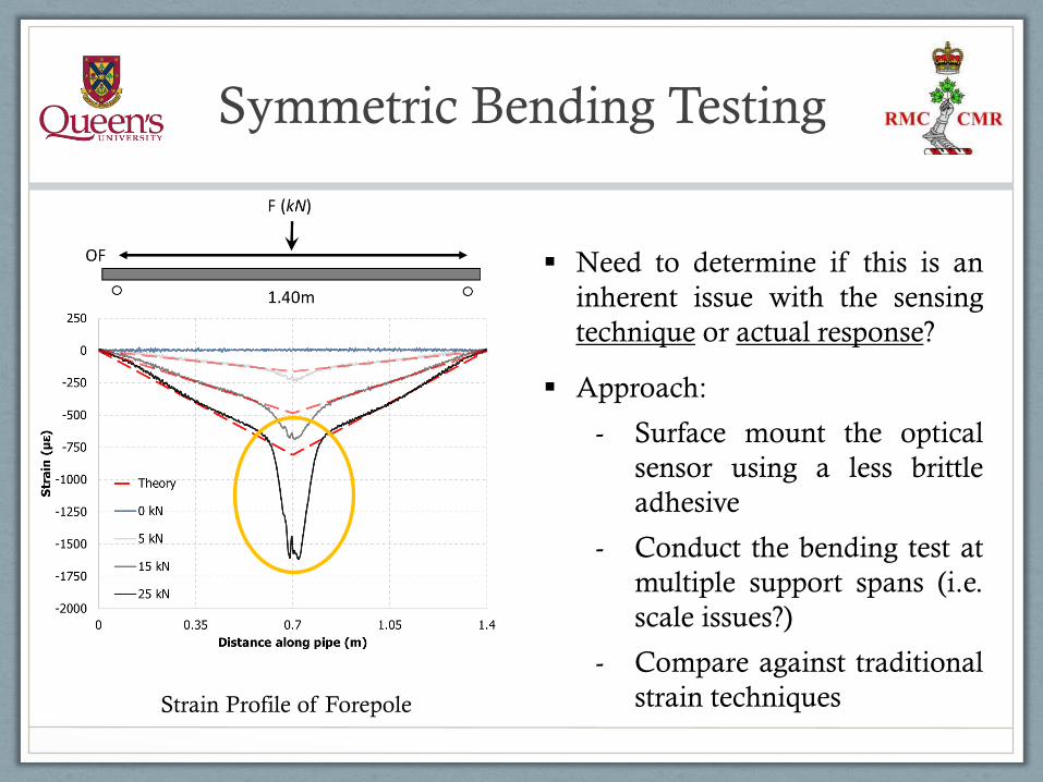
Symmetric Bending Testing
Strain Profile of Forepole
Need to determine if this is an
inherent issue with the sensing
technique or actual response?
Approach:
- Surface mount the optical
sensor using a less brittle
adhesive
- Conduct the bending test at
multiple support spans (i.e.
scale issues?)
- Compare against traditional
strain techniques
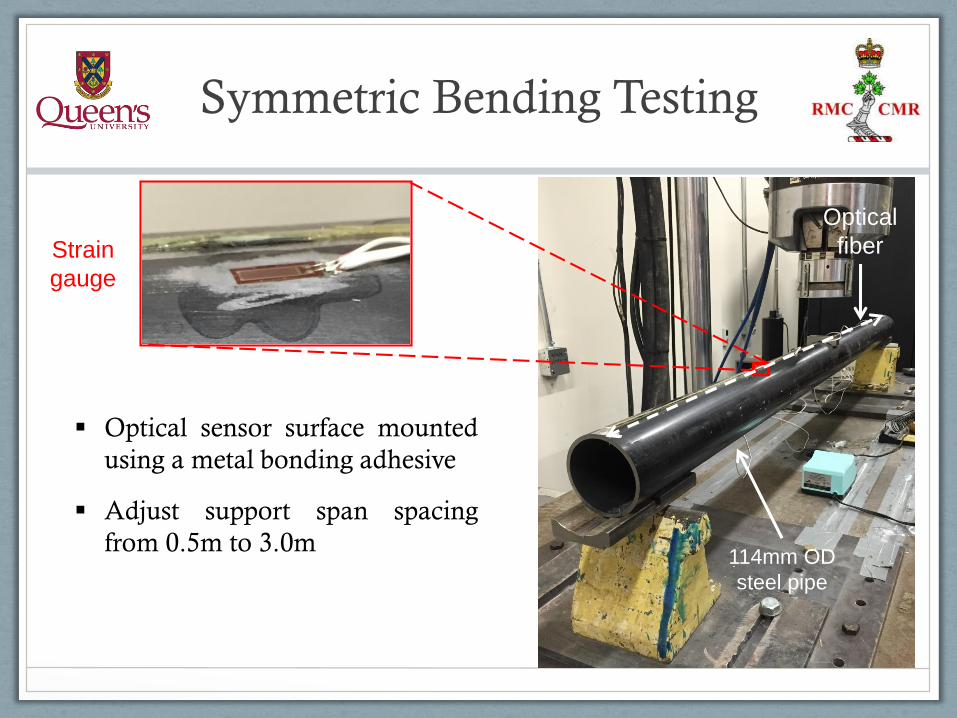
Symmetric Bending Testing
Optical sensor surface mounted
using a metal bonding adhesive
Adjust support span spacing
from 0.5m to 3.0m114mm OD
steel pipe
Optical
fiberStrain
gauge

Symmetric Bending Testing
Strain Profile: 0.66m Support Spacing Strain Profile: 1.90m Support Spacing
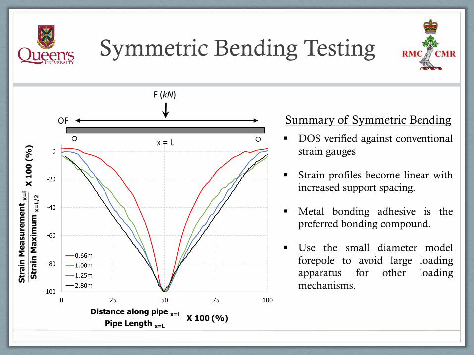
Symmetric Bending Testing
Summary of Symmetric Bending
DOS verified against conventional
strain gauges
Strain profiles become linear with
increased support spacing.
Metal bonding adhesive is the
preferred bonding compound.
Use the small diameter model
forepole to avoid large loading
apparatus for other loading
mechanisms.
Distance along pipe x=i_______________________________________________________________________
Pipe Length x=L
X 100 (%)
Str
ain
Me
asu
rem
en
t x
=i
__
__
__
__
__
__
__
__
__
__
__
__
__
__
__
__
__
__
__
__
__
__
__
__
__
__
__
__
__
__
__
__
__
__
__
__
_
Str
ain
Ma
xim
um
x=
L/2
X 1
00
(%
)
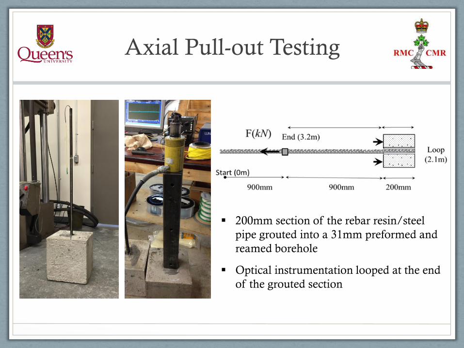
200mm section of the rebar resin/steel
pipe grouted into a 31mm preformed and
reamed borehole
Optical instrumentation looped at the end
of the grouted section
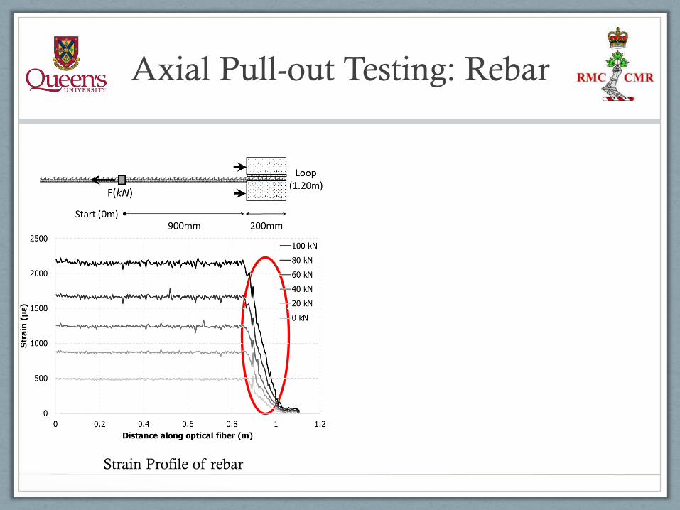
Axial Pull-out Testing
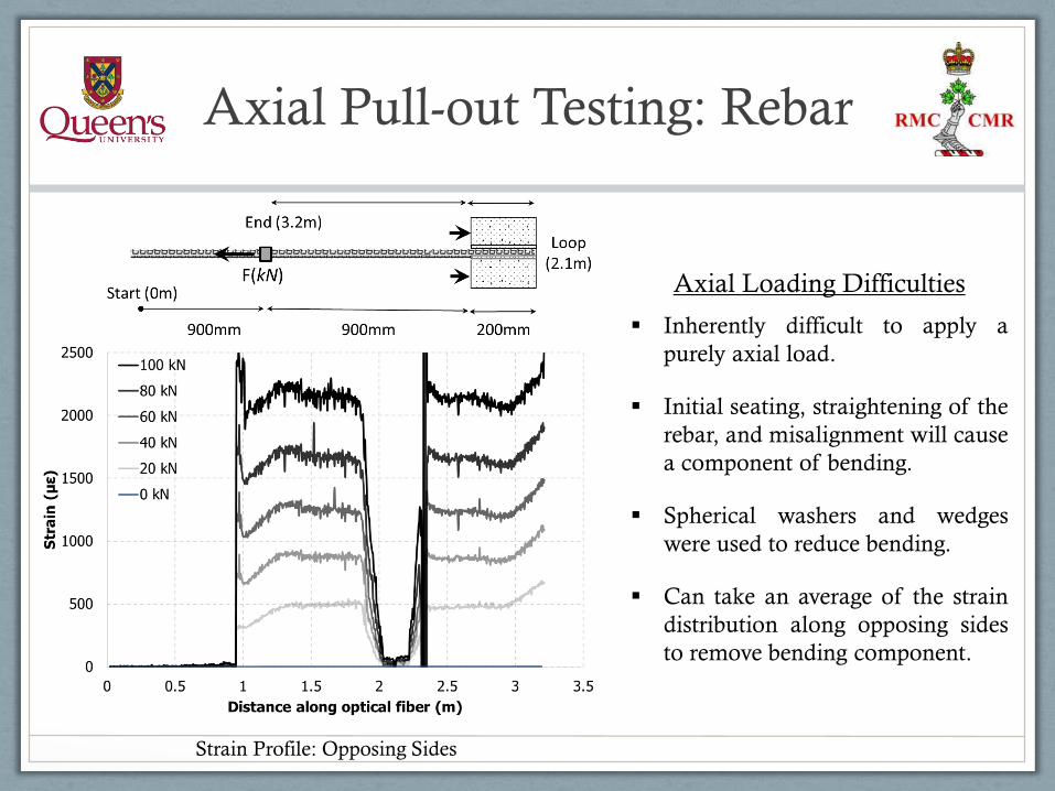
Axial Pull-out Testing: Rebar
Axial Loading Difficulties
Inherently difficult to apply a
purely axial load.
Initial seating, straightening of the
rebar, and misalignment will cause
a component of bending.
Spherical washers and wedges
were used to reduce bending.
Can take an average of the strain
distribution along opposing sides
to remove bending component.
Strain Profile: Opposing Sides

Axial Pull-out Testing: Rebar
Strain Profile of rebar
Axial Pull-out Testing: Rebar
Strain Profile of rebar
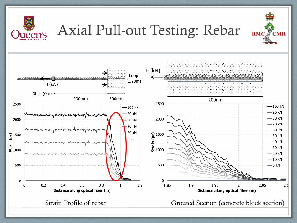
Axial Pull-out Testing: Rebar
Strain Profile of rebar Grouted Section (concrete block section)
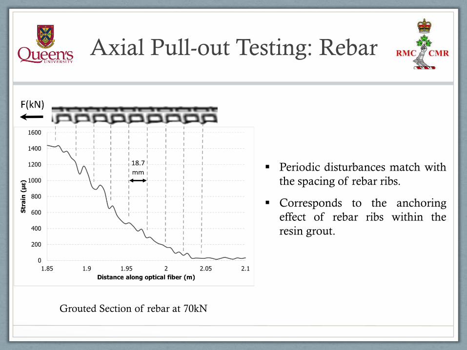
Axial Pull-out Testing: Rebar
Grouted Section of rebar at 70kN
Periodic disturbances match with
the spacing of rebar ribs.
Corresponds to the anchoring
effect of rebar ribs within the
resin grout.
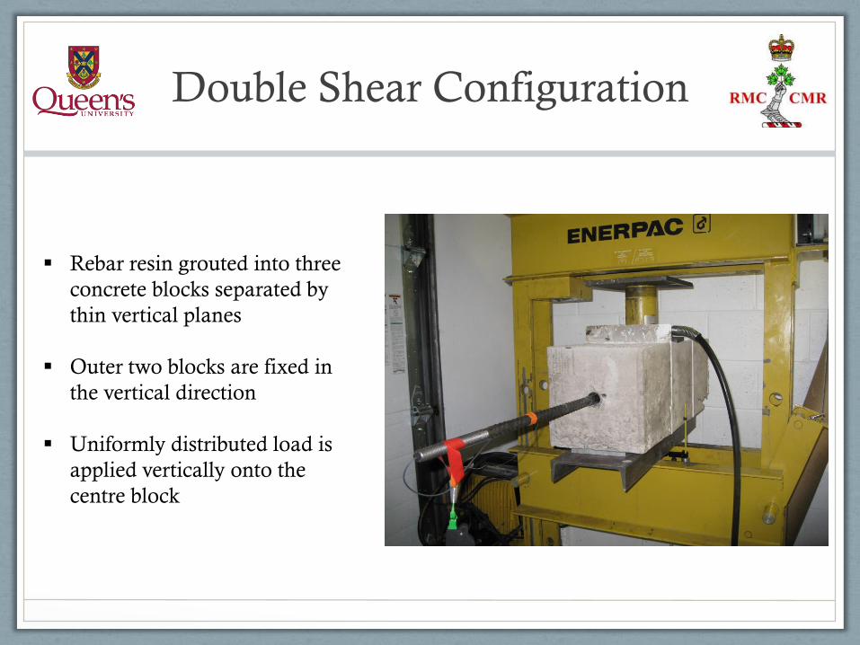
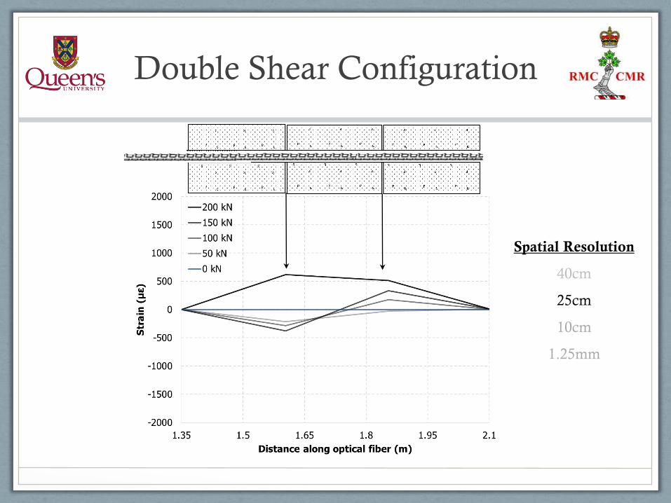
Double Shear Configuration
Rebar resin grouted into three
concrete blocks separated by
thin vertical planes
Outer two blocks are fixed in
the vertical direction
Uniformly distributed load is
applied vertically onto the
centre block

Double Shear Configuration
Spatial Resolution
40cm
25cm
10cm
1.25mm
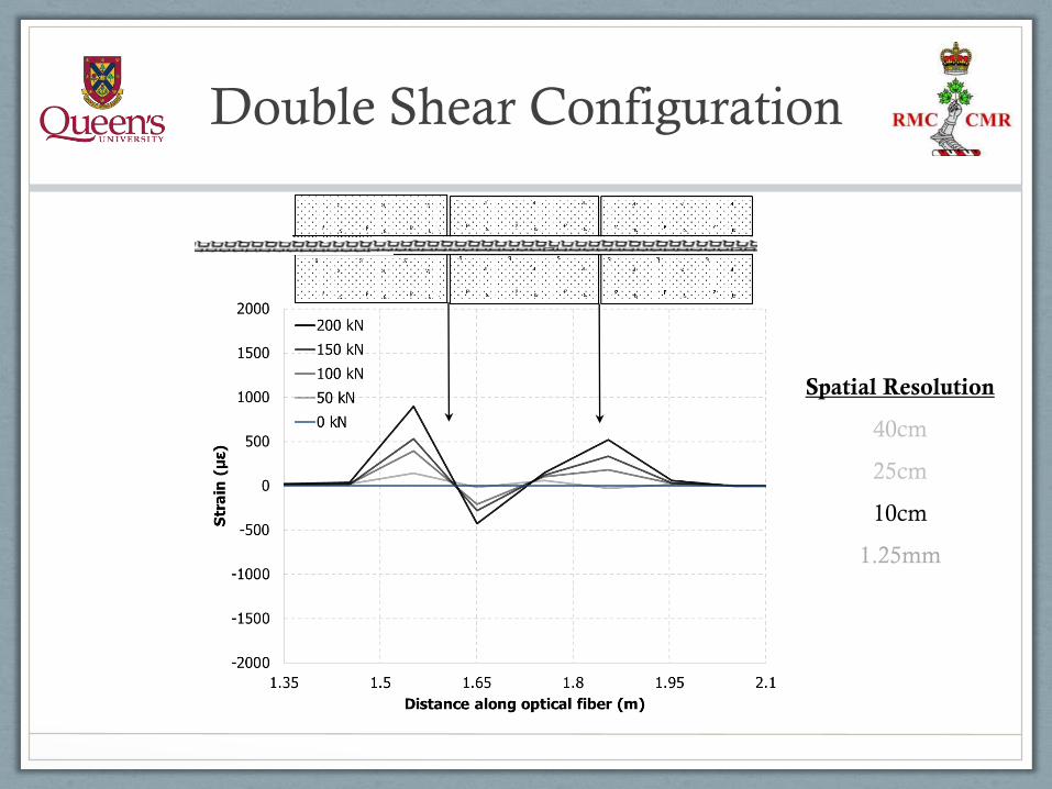
Double Shear Configuration
Spatial Resolution
40cm
25cm
10cm
1.25mm
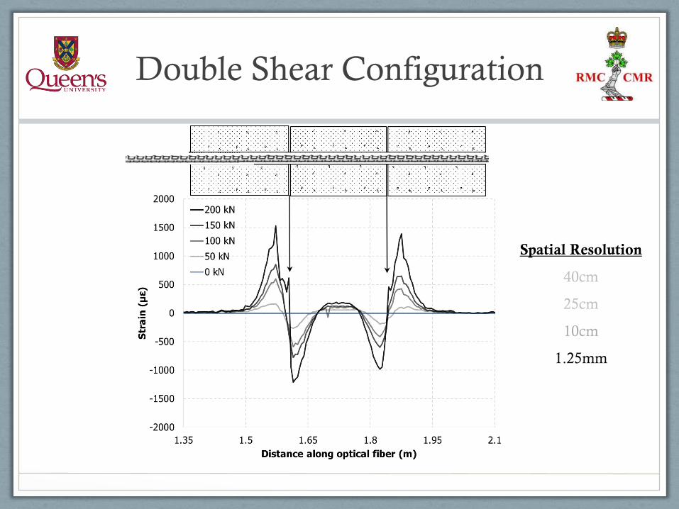
Double Shear Configuration
Spatial Resolution
40cm
25cm
10cm
1.25mm
Double Shear Configuration
Spatial Resolution
40cm
25cm
10cm
1.25mm
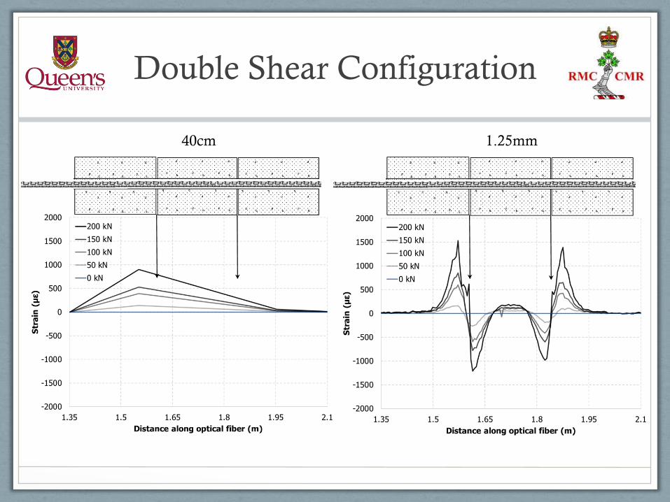
Double Shear Configuration
40cm 1.25mm
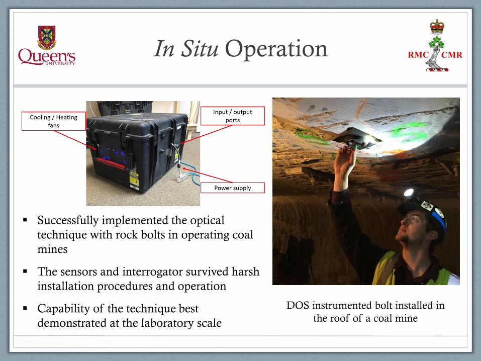
Successfully implemented the optical
technique with rock bolts in operating coal
mines
The sensors and interrogator survived harsh
installation procedures and operation
Capability of the technique best
demonstrated at the laboratory scale
In Situ Operation
DOS instrumented bolt installed in
the roof of a coal mine

Conclusions
An optical sensing technique has been
developed for rock bolt and forepole
support members (laboratory and in situ).
The technique was demonstrated to capture
expected loading mechanisms of support at
an unparalleled resolution and accuracy.
Low-cost per sensor offers an economical
solution for monitoring a cluster of
instrumented support specimens.
The optical solution can be realized as a
novel monitoring tool with the capability to
“see” and “sense” into the ground ahead of
the excavation face
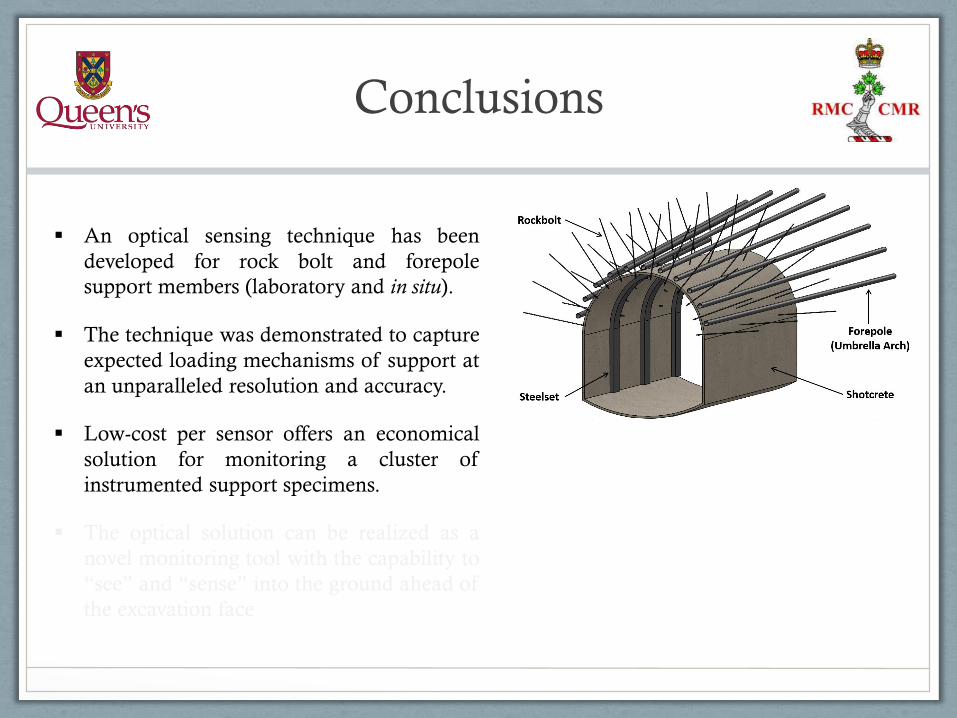
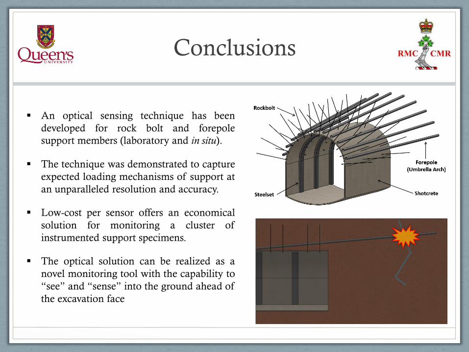

Acknowledgments
• Co-supervision of Dr. Nicholas Vlachopoulos & Dr. Mark S. Diederichs
• Technical support and guidance provided Dr. Andrew J. Hyett of YieldPoint Inc.
• Current and Past Queen’s Geomechanis Group: Special thanks to Dr. Jeffrey Oke
& Ioannis Vazaios
• The Department of Geological Sciences and Geological Engineering at Queen’s
University
• The Department of Civil Engineering at the Royal Military College of Canada
• Funding support provided by: Natural Sciences and Engineering Resource Council
of Canada (NSERC), Department of National Defence (DND), & Nuclear Waste
Management Organization (NWMO)
The Application of Distributed Optical
Sensing for Monitoring Support in
Underground Excavations
Thank You
Bradley J. Forbes