Embed Size (px)
Citation preview
7AAZA 078 FEDERAL AVIATION ADMINISTRATION TECHNICAL CENTER ATL--ETC -F/A 17/7
COAST TERMINAL RADAR APPROACH CONTROL FACILITY (TRACON) REFURBI -ETC(U)
AUG 82 D BOTTOMLEY¥ F F HIERBAUM
UNCLASSIFIED DOT FAA CT-82/21 NLmmmul//r /mr=WIIIiH iJLJL
DOT/FAAIRD82/38Co sRa rDOT/FAACT-82/2 1 CatTerminal RdrApproach
Control Facility (TRACON)Refurbishment
Donald Bottom leyFelix F. Hierbaum, Jr.
Prepared By
FAA Technical CenterC0 Atlantic City Airport, N.J. 08405
August 1982
Final Report
This document is available to the U.S. publicthrough the National Technical Informationf Service, Springfield, Virginia 22161.
CtL
~OCT 1 2 1982
US DSPolmsrv f ~Wira9onA
Washington, D.C 20590
92 1012 048
r7==
NOTICE
This document is diseeminated under the sponsorship ofthe Department of Transportation in the interest ofitnformation exchange. The United States Governmentassumes no liability for the contents or use thereof.
The United States Government does not endorse productsor manufacturers. Trade or manufacturer's names appearherein solely because they are considered essential tothe object of this report.
41
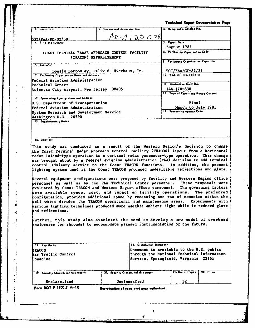
Technical Repot Documetatie. Poeg
1. Repot No. 2. Government Accession No. 3. Recipient's Catalog No.
hTFARD-82 /38 A 0 *eot4.Tteed Svuflo S. Report )at*
August 1982
COAST TERMINAL RADAR APPROACH CONTROL FACILITY 6. Performing Organiztian Cod*
(TRACON) REFURBISHM4ENT7. Performing Organization Report No.I Donald Bottomley. Felix F. Hierbaum, Jr. DOT/FAA/CT-82/21
9. Performing Organization Name and Address 10. Work Unit No. (TRAIS)Federal Aviation Administration
Technical Center 1I. Contract or Grant No.
Atlantic City Airport, New Jersey 08405 144-170-83013. Type of Report and Period Covered
12. Sponsoring Agency Name and Address
U.S. Department of Transportation Finalederal Aviation Administration March to July 1981
iystem Research and Development Service 14. Sponsoring Agency Codeiashington D.C. 20590
15. Supplementary Notes
16. Abstract
This study was conducted as a result of the Western Region's decision to changethe Coast Terminal Radar Approach Control Facility (TRACON) layout from a horizontalradar island-type operation to a vertical radar perimeter-type operation. This changeas brought about by a Federal Aviation Administration (FAA) decision to add terminalontrol advisory service to the Coast TRACON functions. In addition, the presentighting system used at the Coast TRACON produced undesirable reflections and glare.
everal equipment configurations were proposed by facility and Western Region officeersonnel as well as by the FAA Technical Center personnel. These proposals werevaluated by Coast TRACON and Western Region office personnel. The governing factors
ere available space, cost, and impact on facility operations. The preferredonfiguration, provided additional space by recessing one row of consoles within theall which divides the TRAON operational and maintenance areas. Experiments witharious lighting techniques produced more useable ambient light while it reduced glarend reflections.
Further, this study also disclosed the need to develop a new model of overhead?nclosures (or shrouds) to accommodate planned instrumentation of the future.
17. Key Words 18. Oistributlen Statement
!RACON Document is available to the U.S. publicLir Traffic Control through the National Technical Informationonsoles Service, Springfield, Virginia 22161
19. Security Clessif. (of this report) 20. Security Clseif. (of this pege) 21. No. ef Pages 22. Price
Unclassified Unclass if ied 32
* Form DOT F 1700.7 (6-72) Repsaducfien of completed page authorized
--- II----II- -..... ............. ~ ---..... . . . . . .. . . . -.
J .
.1 E
g n I at • L1 1 1
5 4 3 3 1 j5
fill
a
il i 1g II
L ttii ii 1|3
.... ;ii
TABLE OF CONTENTS
Page
INTRODUCTION I
t Purpose 1
Background 1Scope 1
DISCUSSION 4
Foamcore/Plywood Mockup Study 4
Scale Model Study 11Graphic Study 18
Lighting Study 23
CONCLUSIONS 23
RECOMMENDATIONS 23
F -icessiOn FoiriNT S GIRA&I -
.,~L~AityCodea• ' ' llarnd/or
t Scc al
'1 _ __ __ __ _ _ _ _ _ _ _
LIST OF ILLUSTRATIONS
Figure Page
1 Two Views of Present Coast TRACON (2 Sheets) 2
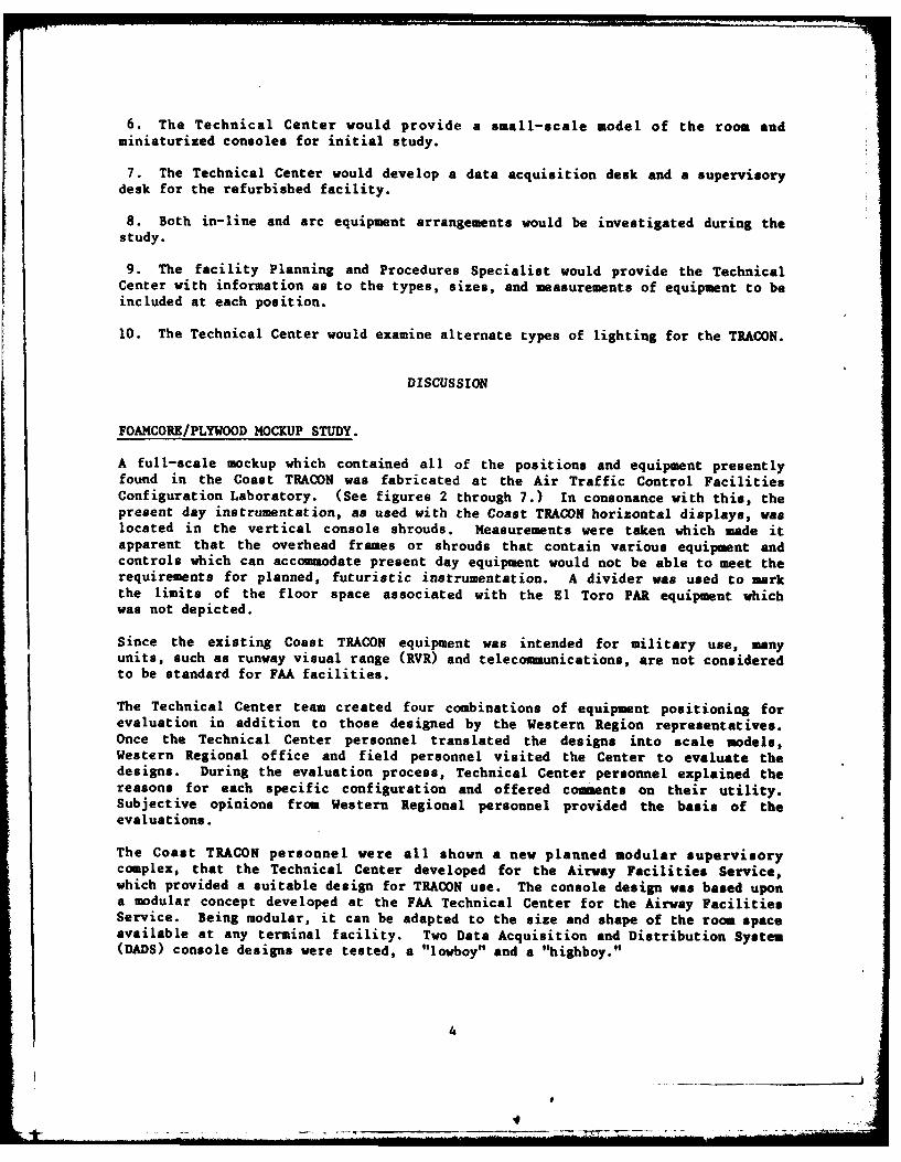
2 "Lowboy" DADS Console (Foreground), Radar and Handoff 5Consoles (Background)
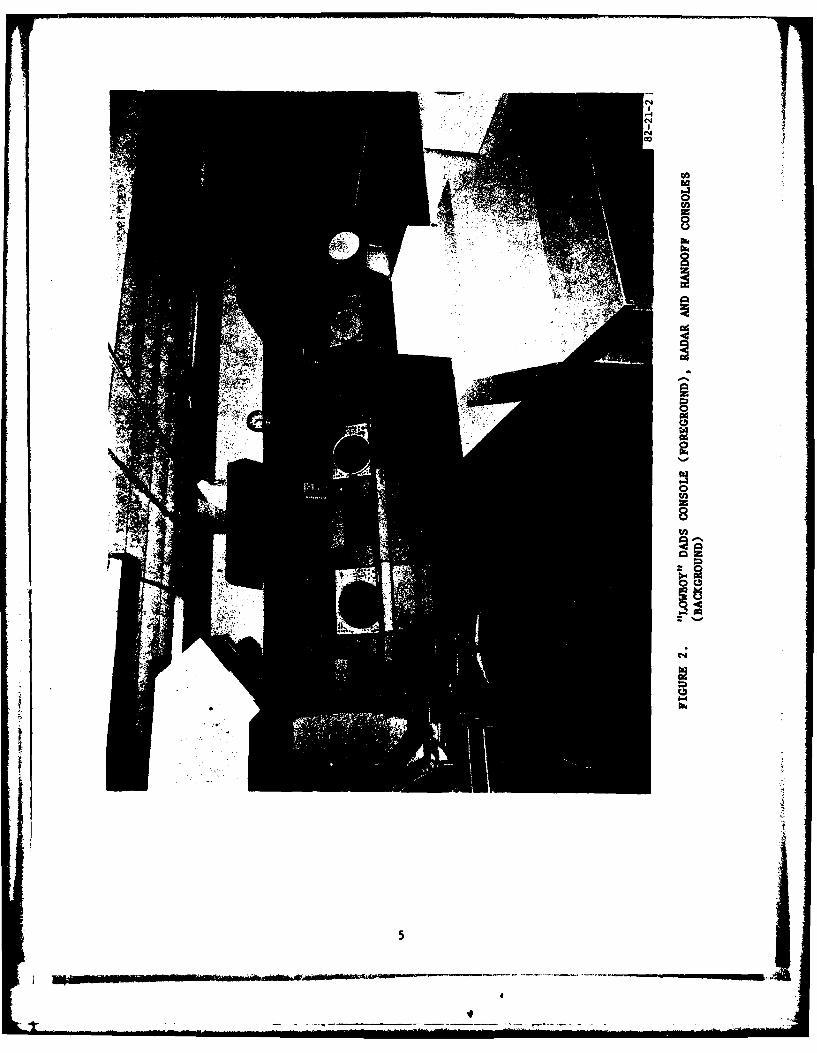
3 Supervisory Console (Foreground); "Lowboy" DADS Console 6and Newport, Pedro, Beach, and Harbor Displays(Background) Plus Associated Handoff Positions
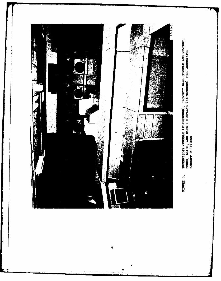
4 Supervisory Console (Foreground); Duke, Orange, and Tustin 7Displays (Background) Plus Associated Handoff Positions
5 Another View of Supervisory Console (Background), Radar 8Displays (Left Side), and Partial "Lowboy" DADS(Right Side)
6 "Highboy" DADS Console, Various Radar Displays (Left and 9Right Background) Plus Associated Handoff Positions
7 Main Ingress/Egress Route 10
8 Configuration 1 12
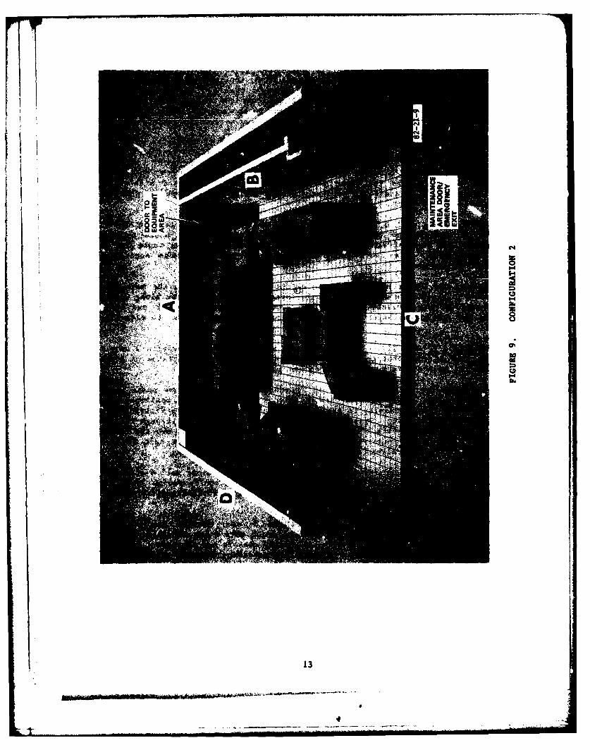
9 Configuration 2 13
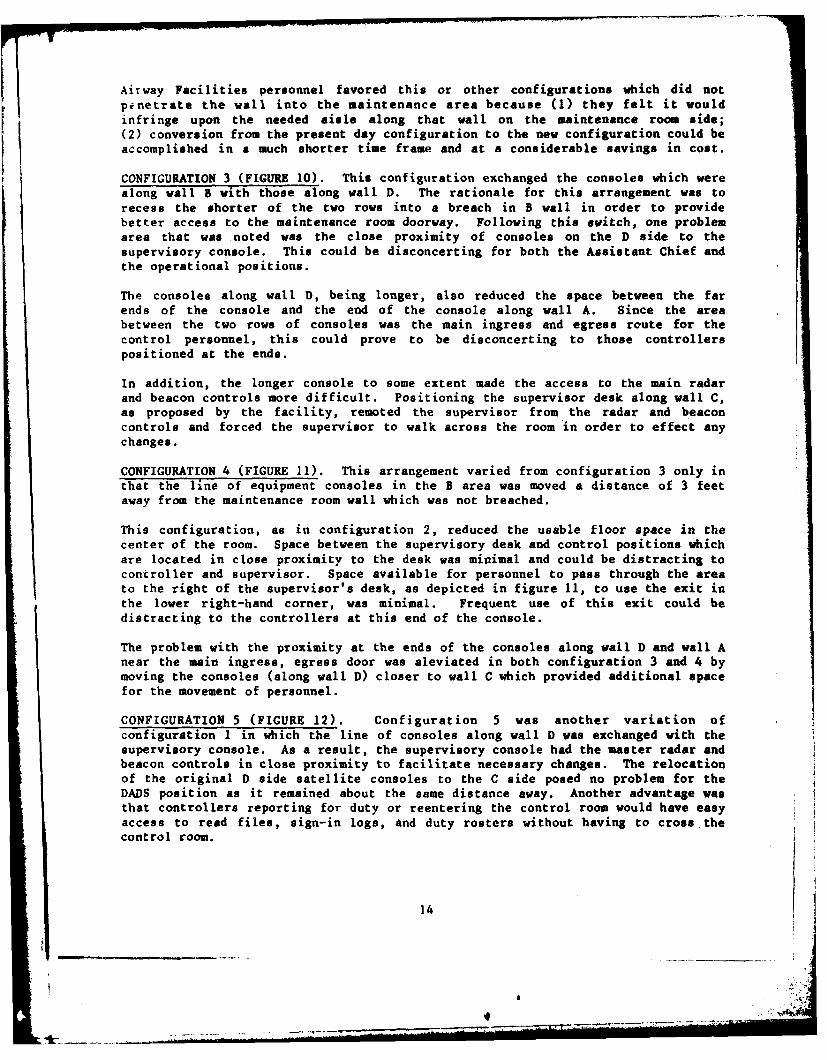
10 Configuration 3 15
11 Configuration 4 16
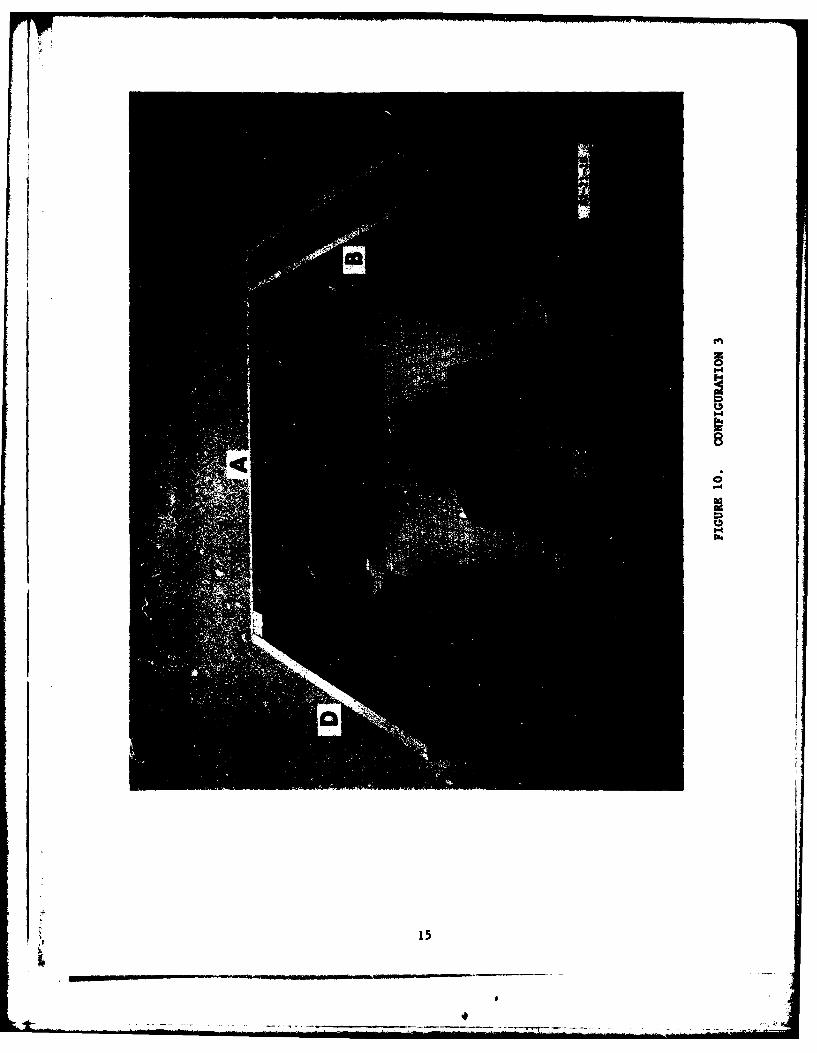
12 Configuration 5 17
13 Configuration 6 19
14 Configuration 7 20
15 Configuration 8 21
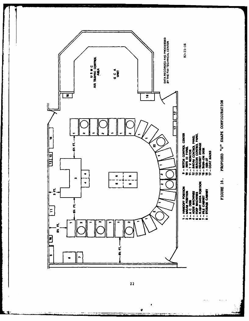
16 Proposed "U" Shape Configuration 22
17 Wall Washing Light - Positioned Low 24
18 Wall Washing Light - Positioned Medium 25
19 Wall Washing Light - Positioned High 26
iv
INTRODUCTION
PURPOSE.
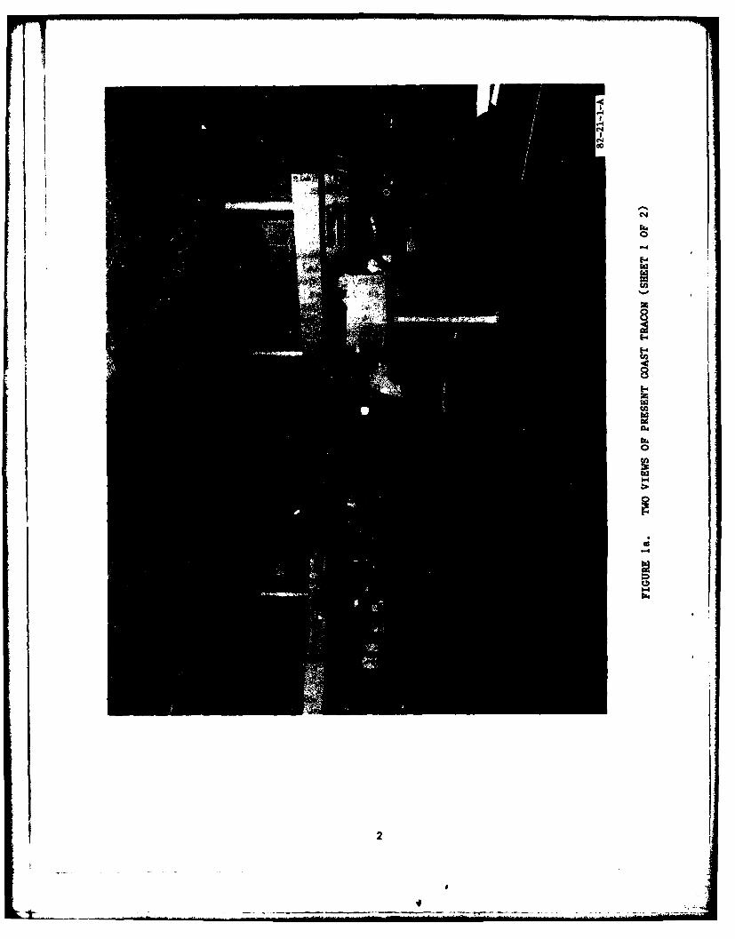
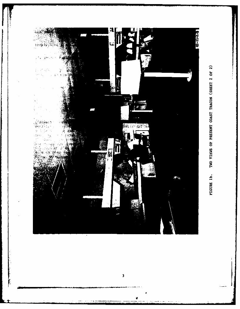
The purpose of this study was to assist the Western Region in the selectionof an appropriate design for the Coast Terminal Radar Approach Control Facility(TRACON) including improved room lighting conditions. (Figures la and lb show twoviews of the present Coast TRACON.
BACKGROUND.
Thq effort was conducted in response to a request from the Western RegionalOffice for the Federal Aviation Administration (FAA) Technical Center to utilizeits mockup techniques and facilities to develop a new equipment configuration forthe Coast TRACON. This request resulted from an FAA decision to establish aTerminal Control Advisory (TCA) Service at the Coast TRACON. This additionalservice necessitated the expansion of the TRACON's operating postions. The regionalso opted to convert the facility's horizontal radar-island configuration toa vertical radar perimeter type. Project restrictions involved room size,maintenance constraints, and alteration costs. The Technical Center was alsorequested to investigate means by which the current room lighting could beimproved.
Coast TRACON is a combined military and civilian Air Traffic Control (ATC) facilitywhich is located at the E1 Toro Marine Corps Air Station in Santa Ana, California.The reconfigured TRACON will have a relatively short lifeean as plans are underconsideration to merge the Coast TRACON with other FAA facilities.
SCOPE.
At a planning meeting between Technical Center and Western Region personnel,the following parameters were established for the refurbishment study:
1. The amount of space available to the Coast TRACON measured 38 feet longby 34.33 feet wide.
2. The wall separating the TRACON and maintenance rooms would be breached soradar displays could be pulled from the rear. (Airway Facilities personnel werereluctant to use this method as they felt it might infringe on the space requiredfor the movement of equipment through the room.)
3. Most equipment would be relocated, as required, with the exception of the radarand beacon controls, the teletypewriter, and the military precision approach radar(PAR) equipment.
4. Ten vertical displays and associated operating positions would be included inthe refurbished area. Shrouds and spacers would be standard equipment, issued byOklahoma City.
5. The Technical Center would mock up the entire TRACON room. Although proposedconfigurations would be provided by the facility, the Technical Center woulddevelop other arrangements.
[ "---
c.J
C-4
F-'
LI8E-4
0
rzl
U-4
2
I.
"Ito
6. The Technical Center would provide a small-scale model of the room andminiaturized consoles for initial study.
7. The Technical Center would develop a data acquisition desk and a supervisorydesk for the refurbished facility.
8. Both in-line and arc equipment arrangements would be investigated during thestudy.
9. The facility Planning and Procedures Specialist would provide the TechnicalCenter with information as to the types, sizes, and measurements of equipment to beincluded at each position.
10. The Technical Center would examine alternate types of lighting for the TRACON.
DISCUSSION
FOAMCORE/PLYWOOD MOCKUP STUDY.
A full-scale mockup which contained all of the positions and equipment presentlyfound in the Coast TRACON was fabricated at the Air Traffic Control FacilitiesConfiguration Laboratory. (See figures 2 through 7.) In consonance with this, thepresent day instrumentation, as used with the Coast TRACON horizontal displays, waslocated in the vertical console shrouds. Measurements were taken which made itapparent that the overhead frames or shrouds that contain various equipment andcontrols which can accommodate present day equipment would not be able to meet therequirements for planned, futuristic instrumentation. A divider was used to markthe limits of the floor space associated with the El Toro PAR equipment whichwas not depicted.
Since the existing Coast TRACON equipment was intended for military use, manyunits, such as runway visual range (RVR) and telecommunications, are not consideredto be standard for FAA facilities.
The Technical Center team created four combinations of equipment positioning forevaluation in addition to those designed by the Western Region representatives.Once the Technical Center personnel translated the designs into scale models,Western Regional office and field personnel visited the Center to evaluate thedesigns. During the evaluation process, Technical Center personnel explained thereasons for each specific configuration and offered comments on their utility.Subjective opinions from Western Regional personnel provided the basis of theevaluations.
The Coast TRACON personnel were all shown a new planned modular supervisorycomplex, that the Technical Center developed for the Airway Facilities Service,which provided a suitable design for TRACON use. The console design was based upona modular concept developed at the FAA Technical Center for the Airway FacilitiesService. Being modular, it can be adapted to the size and shape of the room spaceavailable at any terminal facility. Two Data Acquisition and Distribution System(DADS) console designs were tested, a "lowboy" and a "highboy."
4
. --..-#--.--
'K'6.30U2
00
00
0
B
t
C~d
0'-4
5
I*4
* w
f4~. Ii
ca
6t
'-4
0 z
0
0CA
C02
TAO
to)..
t
l.a(0
(a'-4a
ii0:
(0
*-'M'-4
0'a
8

'-4
A
8 ccAo1-
I
C,
C,~~4
10
'I
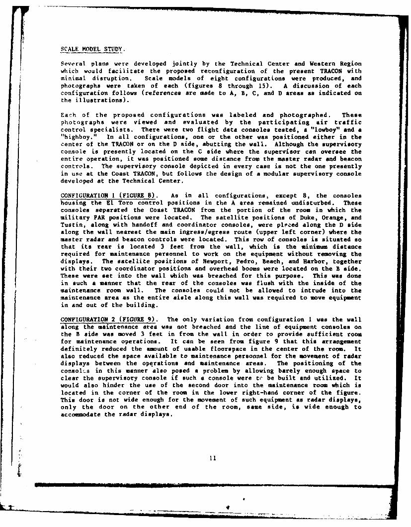
SCALE MODEL STUDY.
Several plans were developed jointly by the Technical Center and Western Regionwhich would facilitate the proposed reconfiguration of the present TRACON withminimal disruption. Scale models of eight configurations were produced, andphotographs were taken of each (figures 8 through 15). A discussion of eachconfiguration follows (references are made to A, B, C, and D areas as indicated onthe illustrations).
Each of the proposed configurations was labeled and photographed. Thesephotographs were viewed and evaluated by the participating air trafficcontrol specialists. There were two flight data consoles tested, a "lowboy" and a"highboy." In all configurations, one or the other was positioned either in thecenter of the TRACON or on the D side, abutting the wall. Although the supervisoryconsole is presently located on the C side where the supervisor can oversee theentire operation, it was positioned some distance from the master radar and beaconcontrols. The supervisory console depicted in every case is not the one presentlyin use at the Coast TRACON, but follows the design of a modular supervisory consoledeveloped at the Technical Center.
CONFIGURATION I (FIGURE 8). As in all configurations, except 8, the consoleshousing the El Toro control positions in the A area remained undisturbed. Theseconsoles separated the Coast TRACON from the portion of the room in which themilitary PAR positions were located. The satellite positions of Duke, Orange, andTustin, along with handoff and coordinator consoles, were placed along the D sidealong the wall nearest the main ingress/egress route (upper left corner) where themaster radar and beacon controls were located. This row of consoles is situated sothat its rear is located 3 feet from the wall, which is the minimum distancerequired for maintenance personnel to work on the equipment without removing thedisplays. The satellite positions of Newport, Pedro, Beach, and Harbor, togetherwith their two coordinator positions and overhead booms were located on the B side.These were set into the wall which was breached for this purpose. This was donein such a manner that the rear of the consoles was flush with the inside of themaintenance room wall. The consoles could not be allowed to intrude into themaintenance area as the entire aisle along this wall was required to move equipmentin and out of the building.
CONFIGURATION 2 (FIGURE 9). The only variation from configuration I was the wallalong the maintenance area was not breached and the line of equipment consoles onthe B side was moved 3 feet in from the wall in order to provide sufficient roomfor maintenance operations. It can be seen from figure 9 that this arrangementdefinitely reduced the amount of usable floorspace in the center of the room. Italso reduced the space available to maintenance personnel for the movement of radardisplays between the operations and maintenance areas. The positioning of theconsoles in this manner also posed a problem by allowing barely enough space toclear the supervisory console if such a console were t4- be built and utilized. Itwould also hinder the use of the second door into the maintenance room which islocated in the corner of the room in the lower right-hand corner of the figure.This door is not wide enough for the movement of such equipment as radar displays,only the door on the other end of the room, same side, is wide enough toaccommodate the radar displays.
411
-_ .. . _ _ _ _ _ _
-fit
12-
00
C-4
04
-1-
13
Airway Facilities personnel favored this or other configurations which did notpenetrate the wall into the maintenance area because (1) they felt it wouldinfringe upon the needed aisle along that wall on the maintenance room side;(2) conversion from the present day configuration to the new configuration could beaccomplished in a much shorter time frame and at a considerable savings in cost.
CONFIGURATION 3 (FIGURE 10). This configuration exchanged the consoles which werealong wall B with those along wall D. The rationale for this arrangement was torecess the shorter of the two rows into a breach in B wall in order to providebetter access to the maintenance room doorway. Following this switch, one problemarea that was noted was the close proximity of consoles on the D side to thesupervisory console. This could be disconcerting for both the Assistant Chief andthe operational positions.
The consoles along wall D, being longer, also reduced the space between the farends of the console and the end of the console along wall A. Since the areabetween the two rows of consoles was the main ingress and egress route for thecontrol personnel, this could prove to be disconcerting to those controllerspositioned at the ends.
In addition, the longer console to some extent made the access to the main radarand beacon controls more difficult. Positioning the supervisor desk along wall C,as proposed by the facility, remoted the supervisor from the radar and beaconcontrols and forced the supervisor to walk across the room in order to effect anychanges.
CONFIGURATION 4 (FIGURE 11). This arrangement varied from configuration 3 only inthat the line of equipment consoles in the B area was moved a distance of 3 feetaway from the maintenance room wall which was not breached.
This configuration, as in configuration 2, reduced the usable floor space in thecenter of the room. Space between the supervisory desk and control positions whichare located in close proximity to the desk was minimal and could be distracting toconcroller and supervisor. Space available for personnel to pass through the areato the right of the supervisor's desk, as depicted in figure 11, to use the exit inthe lower right-hand corner, was minimal. Frequent use of this exit could bedistracting to the controllers at this end of the console.
The problem with the proximity at the ends of the consoles along wall D and wall Anear the main ingress, egress door was aleviated in both configuration 3 and 4 bymoving the consoles (along wall D) closer to wall C which provided additional spacefor the movement of personnel.
CONFIGURATION 5 (FIGURE 12). Configuration 5 was another variation ofconfiguration I in which the line of consoles along wall D was exchanged with thesupervisory console. As a result, the supervisory console had the master radar andbeacon controls in close proximity to facilitate necessary changes. The relocationof the original D side satellite consoles to the C side posed no problem for theDADS position as it remained about the same distance away. Another advantage wasthat controllers reporting for duty or reentering the control room would have easyaccess to read files, sign-in logs, and duty rosters without having to cross thecontrol room.
14
m0N
NI8a-4
N
a '- ..,
15
4

14
8
16
0
'-4I-'
178
CONFIGURATION 6 (FIGURE 13). The only change from configuration 5 was the movement
of the B line of consoles 3 feet away from the maintenance wall which was not
breached. This placement of those consoles again limited the available space
at the far end of the console and the end of the consoles along A. Here radar.
displays could not be removed from the TRACON or brought into the TRACON without
interferring with the controllers at the end positions. Those controllers would
have to move away from the control positions until the equipment passed through the
area.
Here too, if heavy use were made of the doorway in the lower right-hand corner of
the room (figure 13), there could be some distraction to the controllers working at
the positions at this end of the consoles due to their close proximity.
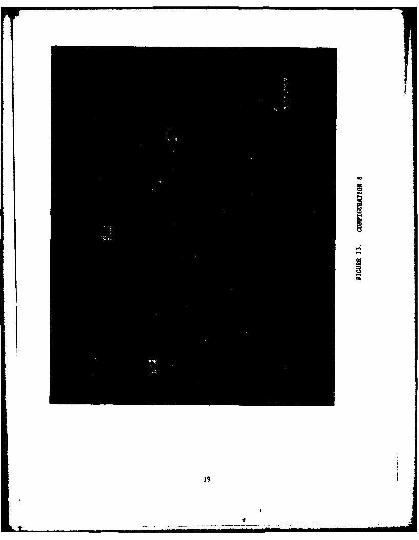
CONFIGURATION 7 (FIGURE 14). Configuration 7 was basically the same as
configuration 5 except that the DADS position was moved to the D side and the
consoles along wall B were recessed into the wall. This arrangement opened up the
center of the floor. Its only disadvantage would be the additional distance flight
data personnel would be required to travel to and from the control sector. This
appeared to be the best configuration because there was more than enough walking
room in the central area, and the ingress/egress route was open. The other two
areas which provided entry into the maintenance area were relatively open also.
Since the consoles along wall B did not actually intrude into the maintenance area,
Airway Facilities personnel found the configurations acceptable.
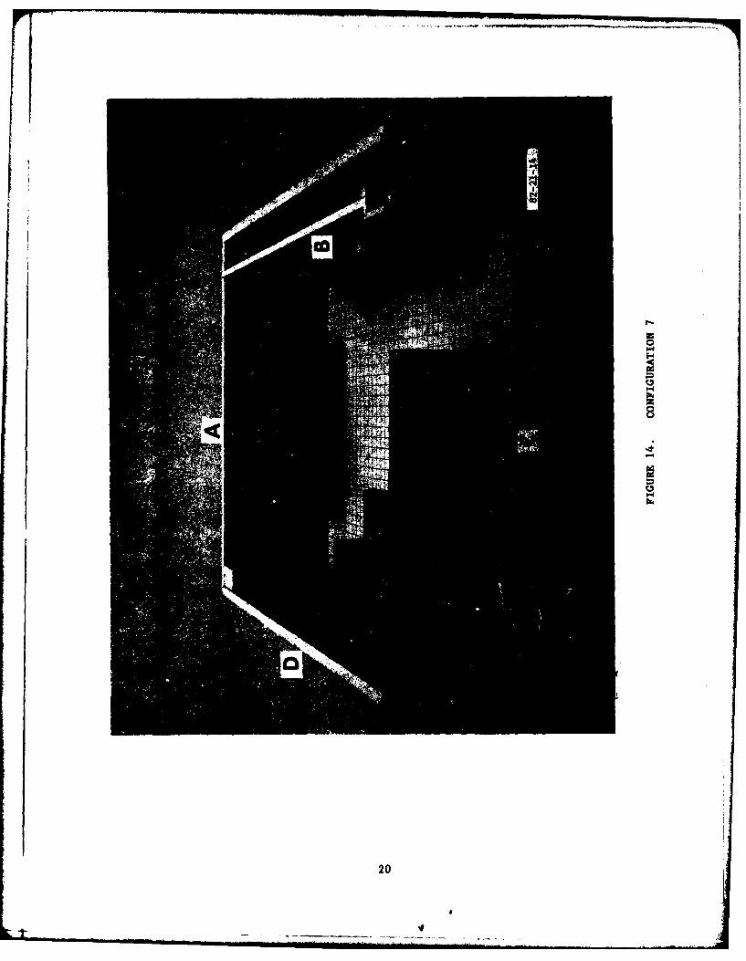
CONFIGURATION 8 (FIGURE 15). Configuration 8 was the same as configuration 7 with
the following exceptions: The consoles along wall B were placed 3 feet away from
the wall and the wall was not breached. In an attempt to provide space between
the far end of the consoles for maintenance to move equipment through, with less
distraction to the controllers, the consoles along walls A and C were moved to the
left, 2 feet. This did provide additional space, however, this did not eliminate
the necessity of the movement of those controllers at the end positions when large
equipment would have to be moved through that area between A and B. During the
evaluation process, the Coast TRACON personnel were shown a new modular supervisory
complex (figure 4). The proposed location for this was near the entrance door
close by the radar and beacon master controls. Also shown were two modular DADS
positions; one was a specially designed "lowboy" version which allowed location in
the center of the room with task lighting via Lightolier" fixtures from the ceiling
(see figures 2 and 3); the other was a two-Flight Data Entry Position (FDEP)"highboy" with self-contained lighting which was planned for a wall position
'(figure 6).
GRAPHIC STUDY.
Another configuration which was considered was that of the "U" equipment
arrangement. (See figure 16.) This configuration was provided by the Western
Region. The alcove which contains the United States Marine Corps air traffic
control area iu depicted as wall A in configurations I through 7. The Western
Region added some consoles which were not depicted in the other studies. A
Technical Center draftsman made a graphic study of this configuration and found it
would not fit within the allotted area, as proposed, and still leave enough room to
transport consoles in and out of the TRACON room into the maintenance area for
servicing.
18
Rlra 4
19I
I-
05.4
C,I-.
B
4
-4
C,'-4
20
ca0
E9
21-
z
4OOD
Ow
9.4
soME4toLINIolaII~
gig ' ~9
9- '
F 11
22
LIGHTING STUDY.
TRACON lighting has -always been a problem as related to the size of the roomand the type of lighting used. Conditions such as reflections on radar displaysand uneven ambient light levels produce glare in some areas and "black holes" inothers. Coast TRACON, like many others, has experienced these problems, and the
Technical Center was requested to provide suggestions to relieve them. As a resultof previous Technical Center research into the problem, an ansver hab been devised.Using a very soft light, called Ultralume Fluorescence, a method known as "wallwashing," which employs lighting fixture troughs and dimmer switch controls, proved
effective. (See figures 17, 18, and 19.) Placement of each trough is important ait serves a twofold purpose: (1) lighting the floor area behind the consoles whichallows maintenance personnel to conduct repair activities to equipment, and(2) directing light upward to wash the walls and ceiling which were painted with adark, flat paint and produced even, glare-free ambient room lighting levels.Providing this twofold capability would require a trough-type fixture which is openboth on top and bottom. Another innovation ehicb can be found at some otherfacilities makes use of dark colored carpeting to cover wall areas. This materialwould both reduce wall light reflections and lower the ambient noise level. If adetermination was made that the flight data position would be more advantageous inthe center section of the TRACON, lighting for it could be accomplished through theuse of well positioned Lightolier framing lights. These lights can be pinpointedupon the area in use and usually cause no spillover of light to other positions.
CONCLUSIONS
As a result of this study and evaluation, it is concluded that:
1. Configuration 7 is the most useful as it provides the maximm working andwalking space with minimum impact upon the existing facility.
2. The ambient lighting of the TRACON should be free of reflective glare, and the"wall washing" process would do much to alleviate this problem.
3. The present shrouds above the radar and handoff consoles will be inadequate foruse with planned, futuristic instrumentation.
RECOMMENDATIONS
Based on the above conclusions, it is reco mended that:
1. A physical equipment change be made to the Coast Terminal Radar ApproachControl Facility (TRACON) which incorporates the innovations of configuration 7.
2. The "wall washing" lighting technique be implemented to relieve reflectiveglare on radar displays.
3. New radar and handoff console shrouds be developed which will accommodate notonly present-day instrumentation, but that planned for the immediate future.
23
C4
CID
-4
24
CAD
1.4
1.4
-4
25
-7tw aa-
0a-'m
'-4I.'
UU)4
a'-4
0'-4he
r '.-*
26
I
.1


![RADAR OPERATION MANUAL - Standard Horizon OPERATION MANUAL.pdf · Radar Operation Manual Page 7 1. INTRODUCTION 1.0 CONVENTIONS USED Please refer to the legend below: [MENU] If you](https://img.pdfslide.us/doc/110x75/600a98e34c43e0463469ddb0/radar-operation-manual-standard-operation-manualpdf-radar-operation-manual.jpg)