Embed Size (px)
Citation preview
UNCLASSIFIED
AD NUMBER
AD491094
NEW LIMITATION CHANGE
TOApproved for public release, distributionunlimited
FROMDistribution authorized to U.S. Gov't.agencies and their contractors;Administrative/Operational Use; AUG 1960.Other requests shall be referred to DavidTaylor Model Basin, Washington, DC.
AUTHORITY
DTMB ltr, 28 Dec 1965
THIS PAGE IS UNCLASSIFIED
UNCLASSIFIED
AD_491094
DEFENSE DOCUMENTATION CENTERFOR
SCIENTIFIC AND TECHNICAL INFORMATION
CAMERON STATION ALEXANDRIA. VIRGINIA
UNCLASSIFIED
NOTICE: When govemrent or other dravings, speci-fications or other data are used for any purposeother than in connection vith a definitely relatedgovernment procurement operation, the U. S.Government thereby incurs no responsibility, nor anyobligation vhatsoever; and the fact that the Govern-sent may have fozumlated, furnished, or in any waysupplied the said drawingsp specifications, or other
,data is not to be regarded by implication or other-vise as in any manner licensing the holder or anyother person or corporation, or conveying any rightsor permission to mnamacture, use or sell anypatented invention that my in any vay be relatedthereto.
.. .... .. .. ..
C) iquw~u~ ~ INELASTIC LOBAR BUCKIUNG OF. CYLINDRICAL SHELLS
cc UNDER EXTERNAL HYDROSTATIC PRESSURE
by
Thee.. E. R*ytblds
DDC
o Zmr~DDC-IRA D
STRUCTURAL MECHANICS LABORATORY
APPUEDRESEARCH AND DEVELOPMENT REPORT
August1960 Report 1392
INELASTIC LOBAR BUCKLING OF CYLINDRICAL SHELLS
UNDER EXTERNAL HYDROSTATIC PRESSURE
by
Thomas E. Reynolds
August 1960 It rt 1392
S.0;13 03 02
TABLE OF CONTENTSPage
A B ST R A C T ............................................................................................................................ 1
IN T R O D U C T IO N .................................................................................................................. . .
A N A L Y S IS .............................................................................................................................. 2
Plastic Buckling Equations ........................................................................................... . 2
Elastic Buckling Equations ........................................................................................... . 5
Minimization of Expressions for Buckling Pressure ................................................... . 6
Determination of Secant and Tangent Moduli ................................................................ 9
Inelastic B uckling ........................................................................................................... 13
EVALUATION OF THEORY WITH! EXPERIMENTAL DATA ON
STIFFENED CYLINDERS ................................................................................................. 15
C O N C L U SIO N S ...................................................................................................................... 20
ACKNOWLEDGMENTS ........................................................................................................ 20
APPENDIX - DERIVATION OF BUCKLING EQUATIONS ........................................... 21
R E F E R E N C E S ...................................................................................................................... 2 5
LIST OF FIGURES
Figure 1 - Buckling-Mode Parameter 45 as a Function of O W L ................................. 8
Figure 2 - Comparison of Approximate and Exact Methods forDetermining Minimum Buckling Pressure ..................................................... 10
Figure 8 - Typical Stress-Strain Diagram ....................................................................... 11
Figure 4 - Graphical Determination of Buckling Pressure for TwoGeneral Classes of Material ............................................................................ 16
Figure 5 - Compression Curves for Cylinder Materials ................................................. 18
Figure 6 - Comparison of Theoretical and Experimental Collapse Pressures ............ 19
Figure 7 - Coordinate System and Cross Section of Stiffened Shell ........................... 22
LIST OF TABLES
Table 1 - Properties of Cylinders ................................................................................... 17
Table 2 - Comparison of Theoretical and ExperimentalCollapse Pressures ............................................................................................ 17
ii
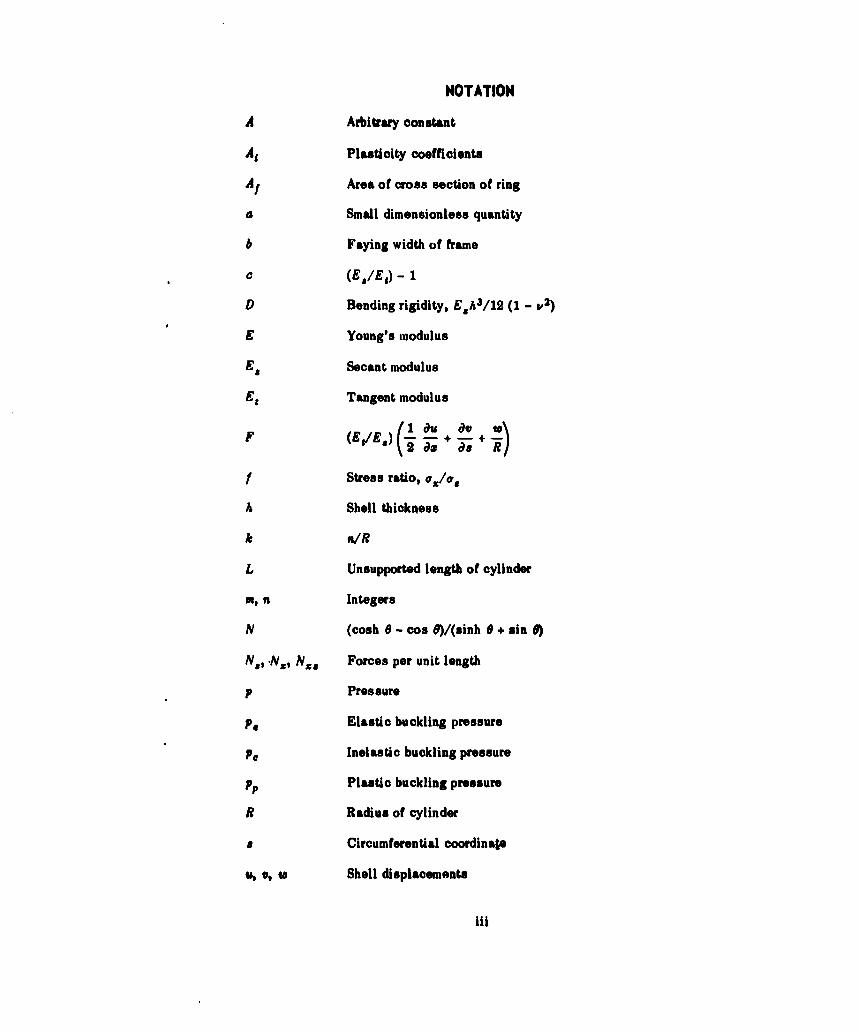
NOTATION
A Arbitrary constant
Ai Plasticity coefficients
At Area of cross section of ring
a Small dimensionless quantity
b Faying width of frame
c (E1/ES) - 1
D Bending rigidity, E.h 3/12 (1 - V2)
E Young's modulus
ES Secant modulus
Et Tangent modulus
F (EgIE,) ( • + T- s + R
f Stress ratio, v1/0%
A Shell thickness
k "IR
L Unsupported length of cylinder
m, n Integers
N (cosh 0 - cos G)/(sinh 0 + sin 0)
N*, .Nx, Nx8 Forces per unit length
p Pressure
Elastic buckling pressure
p. Inelastic buckling pressure
Pp Plastic buckling pressure
R Radius of cylinder
8 Circumferential coordina&P
t, V, W Shell displacements
iii
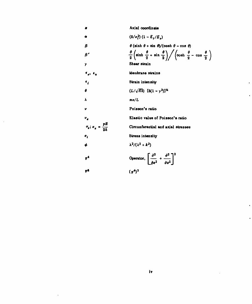
* Axial coordinate
a (3/lr?) (1 - EtIj.)
19 (sinh 0 + sin G)/(oosh 0 - cos 0)
tl "(inh a + sin 0 )/ (osh - - Cos-
Y Shear strain
(9, *X Membrane strains
dji Strain intensity
0 (,IVR7) [3(1 - y2)1%
A mwIL
v Poisson's ratio
Ve Elastic value of Poisson's ratio
0"; aor -•R Circumferential and axial stresses
ori Stress intensity
X2 A A2 + k 2 )
4~ 12~ a2)2Oeaork, - +i
pa (p4)2
iv
ABSTRACT
A solution to Gerard's differential equations for plastic buckling of
cylindrical shells is found for the case of lobar buckling under hydrostatic
pressure. An approximate formula based on this solution is then obtained
for buckling in the inelastic region.
According to this formula, the buckling pressure is a function of the
cylinder geometry and the secant and tangent mnoduli as determined from a
stress-strain intensity diagrain for the shell material. Agreement with
experiments on ring-stiffened cylinders is found to be within 4 percent.
INTRODUCTION
Experimental studies of the buckling of stiffened cylinders under hydrostatic pressure
have shown that collapse of the shell plating between frames is frequently preceded by yield-
ing of the shell material. This would indicate that inelastic shell buckling may be an impor-
tant consideration in the strength design of pressure vessels, particularly when it is realized
that residual welding and rolling stresses often induce inelastic behavior at pressures well
below the design strength.
Inelastic buckling of cylindrical shells induced by external hydrostatic pressure can
take place in two basic modes: axisymmetric buckling, during which circumferential corruga-
tions develop along the axis, and asymmetric or lobar buckling, whereby inward and outward
lobes appear alternately around the circumference. Buckling of Line first type has received
considerable attention, but it has usually been treated as a failure due to yielding rather than
a buckling phenomenon. Typically, an analysis is based on the concept of an ideal material
which, at a certain stress level, undergoes an abrupt transition to the perfectly plastic state.
The buckling pressure is determined not from stability considerations but from the state-of.
equilibrium stresses. Attempts to describe buckling of the second type have been rather
limited and have usually depended on the intuitive use of a reduced modulus in place of
Young's modulus in the elastic buckling equation.
In recent years, however, advances in plasticity theory have made it possible to ap-proach these problems more rigorously. Investigations by Bijlaard, 1,2 llyushin, 3 and
Stowell, 4 among others, have contributed greatly to the development of theory for the inelas-
tic buckling of plates and shells. More recently, Gerards derived a general set of differential
equations for cylinders from which he obtained approximate solutions for torsional buckling
and axisymmetric buckling under axial compression for a strain-hardening material.
Lunchick 6 has since developed a similar, but more exact, theory for axisymmetric buckling
Refemences wre Usted on pagoe 2.
of ring-stiffened cylinders under hydrostatic prepsure. From recent tests conducted at the
David Taylor Model Basin, this theory appears to be very reliable.At the same time, it appeared that the work of Gerard might also provide a worthwhile
approach to the problem of asymmetric or lobar buckling in ring-stiffened cylinders, since his
differential equations are sufficiently general to account for asymmetric deformations under
hydrostatic loading. Work was subsequently initiated to obtain a solution to Gerard's equa-
tions for the asymmetric problem. In this report the solution is derived, and an approximate
formula for inAlastic buckling is obtained. Experimental data from ring-stiffened cylinders
are used to evaluate the formula.
ANALYSIS
PLASTIC BUCKLING EQUATIONS
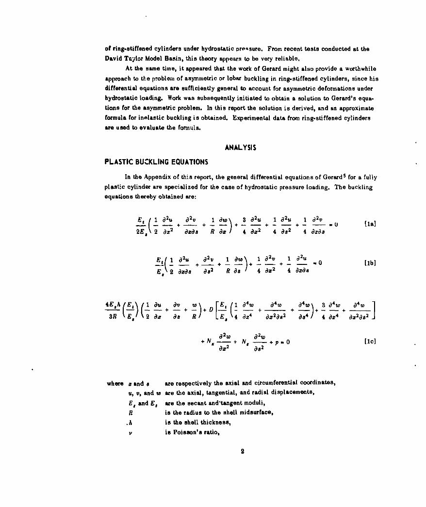
In the Appendix of this report, the general differential equations of Gerards for a fully
plastic cylinder are specialized for the case of hydrostatic pressure loading. The bucklingequations thereby obtained are:
- + - + +- - + - + - 2 + - - U [lal
2E, 2 az2 azas R / 4 az 2 4 &s2 4 dxas
El (1 aU aV 1aW) 1 a2 V 1 a2U.-- - + - + _ -_ + _ - + _ .0 [1b]
2 azas a82 R as/ 4 d 2 4 8:0s
4Egh (f) 1 au 0-v + w)+. [Eg ( 410 C4W a4t- 3 a4w a4 W 1
S+ -( +- ) ( + + [ + + / +
3R' Es a as R Es4 ax4 ax2as2 &84 / 4 ax-4 ax2as2
82 w 02w
+ -NX + NS -+ .0 [1c]aX2 C182
where x and a are respectively the axial and circumferential coordinates,
u, v, and w are the axial, tangential, and radial displacements,
E. and E, are the secant and'tangent moduli,
R is the radius to the shell midsurface,
.h is the shell thickness,
V is Poisson's ratio,
2
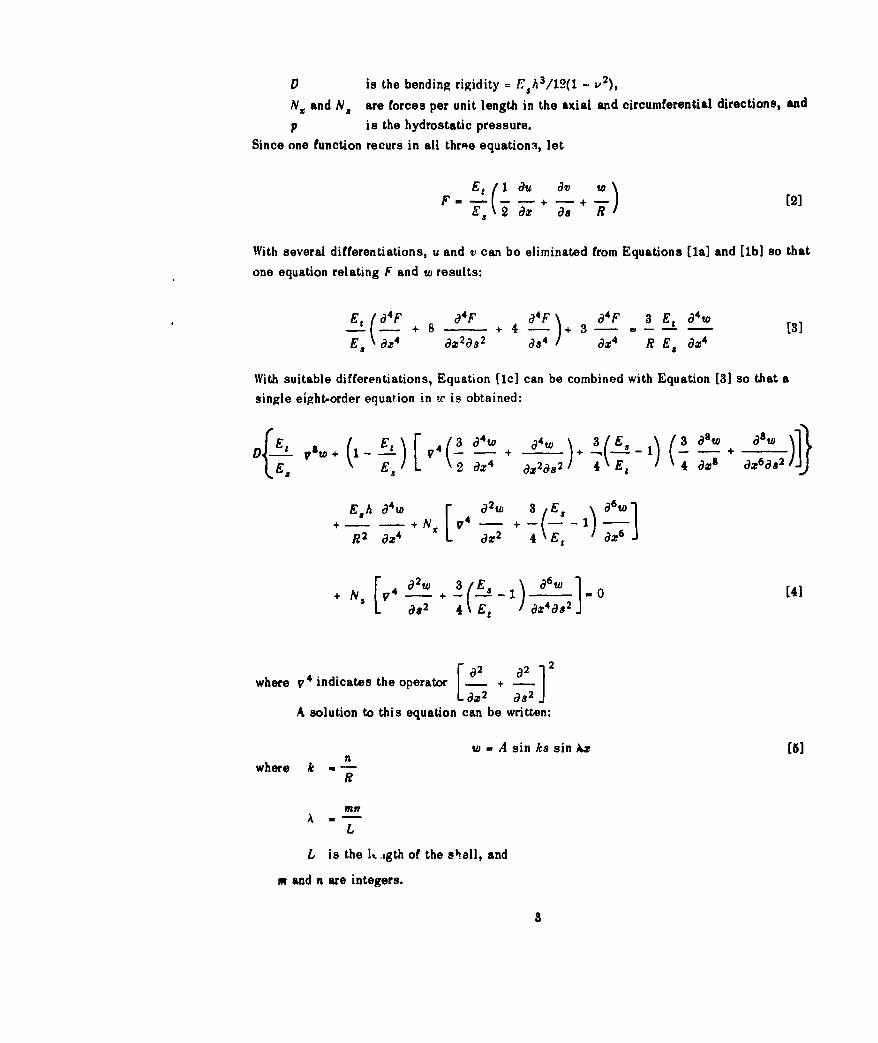
0 is the bending rigidity - Esh 3 /12(1 - v2 ),
NX and Ns are forces per unit length in the axial and circumferential directions, and
p is the hydrostatic pressure.Since one function recurs in all three equation; let
Et (20u av WF M s 9 - - + as + R 2]
With several differentiations, u and v can bo eliminated from Equations [1a] and [1b] so that
one equation relating F and w results:
E ( a 4 F + 8 F 4 F 04 F 3 Et a 4W[
+ 4 - + [3]
ES dX4 az 2as 2 da4 ax4 R Es dx 4
With suitable differentiations, Equation [1c] can be combined with Equation [31 so that a
single eight-order equation in ut is obtained:
~ LV\ 2 a4W w a lE8 5 astow i
+fj 11. ft N V4( - - + - - - 1 ) ( awE 2 a a22 1 2 4 E6 (a)3k a) C+ a~a
E8 A a4W a2w 3,E ~ a6w* -- - + N 74 - +-(. 1
R2 aX4 aX2 4- -E ) aZ]
a82 4 Et ax4a,92J
where v4 indicates the operator [ a2+ a2 12
x2 as2 a
A solution to this equation can be written:
w - A sin ks sin Az [5]where k n
R
my
L
L is the l1. jgth of the shall, and
m and n are integers.
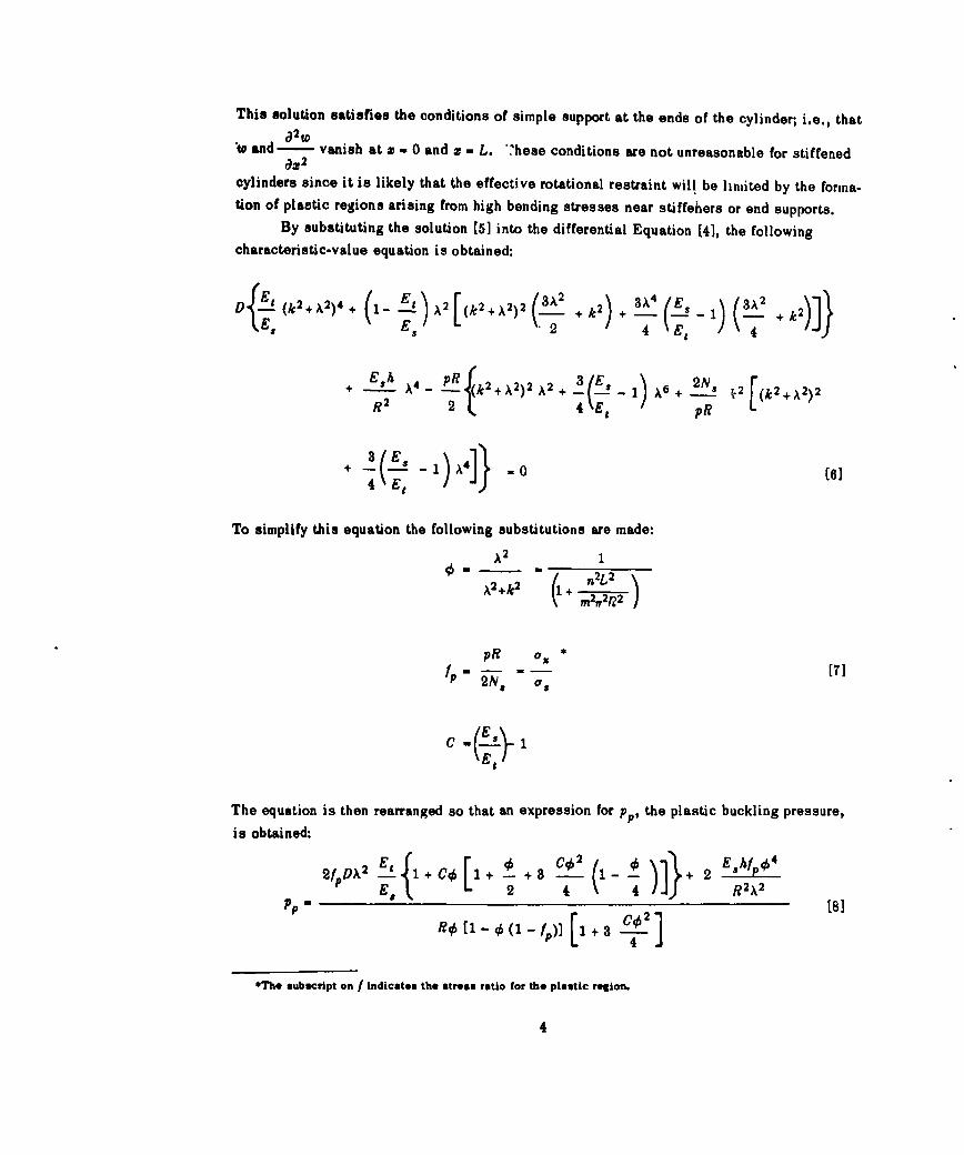
This solution satisfies the conditions of simple support at the ends of the cylinder; i.e., that
"to and-2 vanish at z a 0 and z = L. hese conditions are not unreasonable for stiffenedOX2
cylinders since it is likely that the effective rotational restraint will be limited by the forma.tion of plastic regions arising from high bending stresses near stiffeners or end supports.
By substituting the solution (5] into the differential Equation (4], the followingcharacteristic-value equation is obtained:
2 2 4 E pR
+(--R-2 . 244 Et (6]
4 E
To simplify this equation the following substitutions are made:
A2 1
A2 +k 2 + n2L2(1m2ff2p'-,'
pR O, *
f -- as
ES/
The equation is then rearranged so that an expression for pp, the plastic buckling pressure,
is obtained:
2 #DX E L 2 + 4 4 R 2X2
P [.- 21 [81
T4
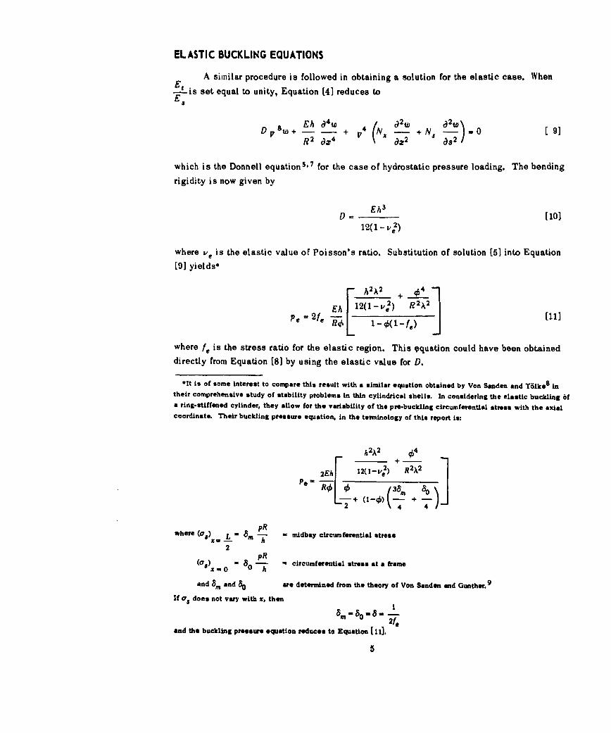
ELASTIC BUCKLING EQUATIONS
A similar procedure is followed in obtaining a solution for the elastic case. When
E- is set equal to unity, Equation [4] reduces to
LA• INV V aw 2 02wtO
DPs8 W+ + ; 4 - +N =0 [ 9]R2 a_4 aX 2 0a2 /
which is the Donnell equation5 ' 7 for the case of hydrostatic pressure loading. The bending
rigidity is now given by
LA 3
D = [10]12(1-mve)
where ve is the elastic value of Poisson's ratio. Substitution of solution [5] into Equation
[9] yields*
- A2A2 + 441
Pe = 2fe E h 12(l - v,2 ) [11]
where f, is the stress ratio for the elastic region. This 9quation could have been obtaineddirectly from Equation [8] by using the elastic value for D.
*It is of some interest to compare this result with a similar equation obtained by Von Sanden and Tdlke 8 intheir comprehensive study of stability problems in thin cylindrical shells. In considering the elastic buckling 6fa ring-stiffened cylinder, they allow for the variability of the pro-buckling circumferential stress with the axialcoordinate. Their buckling pressure equation, in the terminology of this report is:
h 2A2 954
Pe2 R023AM2]
pRwhere (a,) L - -- midbay circumferential stress
X= h2
( a, = 10 -8 circumferentiai stress at a frame
and 8. and 80 are determined from the theory of Von Sanden and Gunther.9
If o, does not vary with x, then
and the buckling pressure equation reduces to Equation [I Il,
5
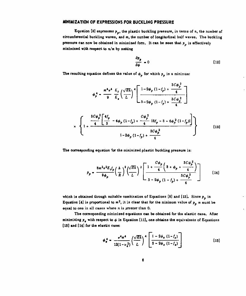
MINIMIZATION OF EXPRESSIONS FOR BUCKLING PRESSURE
Equation (81 expresses pp, the plastic buckling pressure, in terms of n, the number ofcircumferential buckling waves, and m, the number of longitudinal half waves. The bucklingpressure can now be obtained in minimized form. It can be seen that pp is effectively
minimized with respect to n/m by setting
appd- . 0 [12]
The resulting equation defines the value of q5 for which pp is a minimum:
tT-/2m4 -4 E (Vl-4 1 - 2 0, (1-f,) + - 1
44
+ -- - [13]
1-20P (1-fp) + 4-
The corresponding equation for the minimized plastic buckling pressure is:
S2 2E -[1 + C4P 3+ + 3 6:P2
P m vtf( ) 2 .) 2 4 P [141
P ~t 3 -20p(1 -f ) + -
which is obtained through suitable combination of Equations [8] and [13]. Since pp inEquation (4] is proportional to m2, it is clear that for the minimum value of pp m must be
equal to one in all cases where n is greater than 0.The corresponding minimized equations can be obtained for the elastic case. After
minimizing p. with respect to 0 in Equation [111, one obtains the equivalents of Equations
[13] and [14] for the elastic case:
f4M4 4 F1-_2q0 (1-f*(1 2)15]
6
P, 2,r2 rn2Efe (A [ ~ 2 [ 2 e 1 f ) 16]
These equations could also have been obtained directly from Equations (13] and [14]. Again
it is seen that m must be equal to 1. For the case where fe is equal to % corresponding to the
prebuckling state of stress in an unstiffened tube, it can be shown that Equations [151 and
[16] are exactly those given by Windenburg and Trilling (Equations [201 and [21] of Reference
10) in expressing the Von Mises buckling pressure in minimized form.
Although Equations [14] and [16] are relatively simple in form, they contain the func-
tion q6 which is not readily determinable from Equations [13] and [15]. However, it is possi-
ble to obtain an approximate expression for 0b from a graphical representation of these
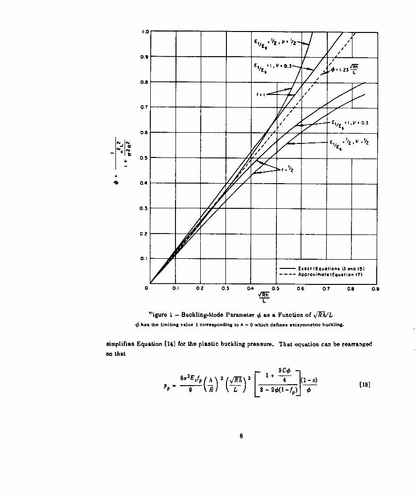
equations. Figure 1 shows plots of qS versus \/W,-/L (with m equal to one) for the following
cases:
E t /e - -Elastic: - _ 1 ie -0.3
1Et 1 1 P=2
Plastic: - - - V -
The value of !, for E,'Es was chosen as a typical case for the plastic region. The two stress
ratios, • and 1, are extreme values which should bound all cases of practical interest. The
curves terminate at the line where j is equal to 1, since this is the case of axisymmetric
(n = 0) buckling for which the minimized pressure expressions no longer have meaning. These
curves suggest that a simple linear relationship Letween 0 and V/T/L might serve as an
adequate approximation for all cases. Use of such an approximation implies that the number
of circumferential lobes is independent of the material properties. After some investigation,the equation
- 1.23 V [171L
represented by the dotted line in Figure 1, was chosen as a reasonably good approximation.*
It is seen that this line falls roughly midway between the extremes of the curves presented.
Use of Equation [17] in conjunction with Equations [14] and [161] then provides approximate
expressions for pP and Pe" It is also helpful to make an additional approximation which
*Actually, the selection of the factor 1.23 was somewhat arbitrary since the buckling pressure is relativelyinsensitive to this parameter so long as it falls between 1.0'end 1.S. In following an equivalent procedure
for minimizing the Von Mises buckling pressure, Windenburg and Trilling1 0 obtained the value 1.265.
7
1.0
0.9
E " 'I/2. & '' '2 10
E .0.3 / R
0.6 /
F12
0.7
Et[, YES I, 0..3/
0.6
0.5
fV~ '/2
0.4
0.3
0.2
0.1
E- Exact (Equations 13 and 1S)-.... Approximate (Equation 17)
0 0.1 0.2 0.3 0.4 0.5 0.6 0.7 0.8 0.9
L
''igure 1 - Buckling-Mode Parameter 96 as a Function of V-RA/L
40 has the limiting value I corresponding to n = 0 which defines axisymmetric buckling.
simplifies Equation [14] for the plastic buckling pressure. That equation can be rearranged
so that
8w2 , fp (A' h ( -Rh 214 (1 -a)P 9 \R L L3 -20(l-f) Q181
8
where
a - o ( = [191
2 3-20(1-fp) + -T--
The subscript on p has been dropped, since the single function 0 is to be used in both the
elastic and plastic regions. It can be seen that a will take on its maximum value when k isequal to 1. For the case Et/Es =, a is 0.091 when 4, is 12, and 0 when is 1. Thus for
all cases where Et/E, Ž V/. 0 < a < 0.091. Since E,/E' will seldom be much smaller than !whereas q will always be less than 1, the approximation that a can be neglected will intro-
duce only small errors. Equation [18] is thus reduced to
91 ( 9-- L 1 [201
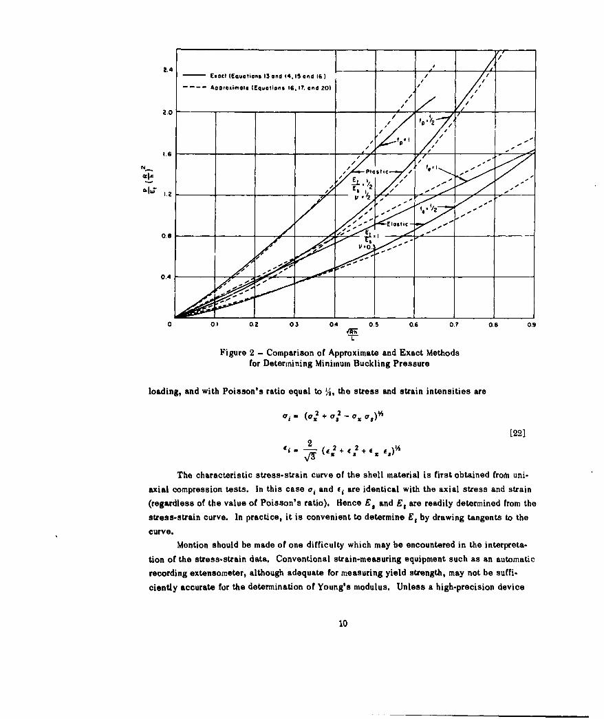
To examine the accuracy of the equations thus obtained, the results of the approximate equa-
tions are compared with those of the exact equations in Figure 2, where --E ) is plotted
a4 a function of -v/7U/L, p being the theoretical buckling pressure. The solid curves representthe exact Equations [141 and [161 for the plastic and elastic cases, respectively, with the
corresponding values of 0 determined from the exact curves of Figure 1. The correspondingapproximate results, indicated in Figure 2 by the dotted curves, are obtained from Equations
[20] and [16] using the approximate expression [17] for j. It is seen that the approximate
method of calculation agrees quite closely with the exact method, even though Figure 1 showswide divergence between the approximate and exact values for 95, particularly in the upperrange of VIM/lL.
DETERMINATION OF SECANT AND TANGENT MODULI
Before iEquation [20] can be used, E. and E, must be related to the applied pressure.
The secant and tangent moduli
E.
[211do.
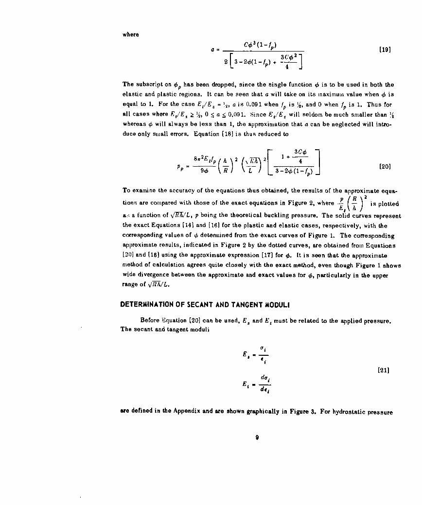
are defined in the Appendix and are shown graphically in Figure 3. For hydrostatic pressure
9
I.4 j /1
2.4 __ _
'- Exact (Equations 13 and 14,15 and i6) //
2.0 Approximate (Equations I. 17, and 20)
S/2.0 ,,-
Iw 1.2
1. Es "/ 7e;2--
0.6 E___
0.4
0 0.1 0.2 03 04 0.5 0.6 0.? 0.8 0.9
Figure 2 - Comparison of Approximate and Exact Methodsfor Determining Minimum Buckling Pressure
loading, and with Poisson's ratio equal to ',., the stress and strain intensities are
S(o,2 + V, - V, a,)
[22]di; (j2 +e,2 + g
The characteristic stress-strain curve of the shell material is first obtained from uni-
axial compression tests. In this case oi and e, are identical with the axial stress and strain
(regardless of the value of Poisson's ratio). Hence £, and E, are readily determined from the
stress-strain curve. In practice, it is convenient to determine E, by drawing tangents to the
curve.Mention should be made of one difficulty which may be encountered in the interpreta-
tion of the stress-strain data. Conventional strain-measuring equipment such as an automatic
recording extensometer, although adequate for measuring yield strength, may not be suffi-
ciently accurate for the determination of Young's modulus. Unless a high-precision device
10
ES ~ E
//
/ /
/ /
/
Figure 3e - Typical Stress-Strain Diagram
//
/
I
/
/
/
/,E..
is employed, it is best to obtain only the relative values E.,/E and E21/E from the stress-strain
data and assume a standard value for E.
Having determined E,/E and Et/E as functions of aj, one must then apply them to thehydrostatically loaded cylindrical shell. According to a fundamental hypothesis of plasticitytheory, the stress and strain intensities are uniquely defined. 4 Thus by expressing hydrostatic
pressure in terms of the stress intensity, a relationship between E., Et, and pressure will be
established. Since equilibrium requires that a. be equal to pR/2h, only 7, in Equation [201remains to be determined. As discussed in the Appendix, a. is actually a continuously vary-
ing function of z, whereas in this theory a. is treated as a constant. Thus a single value of
a. must be chosen, and it is taken to be the stress occurring midway between frames. Sincethis is, generally, the maximum membrane stress in the shell, it might be regarded as aconservative choice. However, it should be noted that for a material exhibiting a plateau-
type stress-strain curve, any other choice would probably overestimate the strength of the
shell.
In calculating a. it is particularly useful to make the further simplifying assumptionthat a. is proportionil to the applied pressure in both the elastic and plastic regions. This
assumption is reasonable provided the deflections of the shell remain small compared withits thickness. Then a. can be determined completely from the theory of Von Sanden and
Gunther 9 with ,equal to !:
11
0.75 -.- 2 [23
where
sinh Op+ sin OpOP- o cosh OP - cos Op
P . OP OP
cosh - - cos2 2
9p = (2.25)'' LR
Af is the cross-sectional area of the frame, and b is the laying width of the frame. The sub-
script p indicates that all functions are given for Poisson's ratio equal to •.
It will be observed that the "beam-column" effect, demonstrated theoretically by
Salerno and Pules, 1 is ignored in the assumption of proportional loading. This effect causes
a departure from proportional loading in the elastic region. However, this departure is ordi-
narily small and, in view of the approximations already made, to account for it would be an
unnecessary refinement. In those cases where the effect is large it can easily be included in
the value assumed for a,.*
The stress ratio for Poisson's ratio equal to 'j is then given by
0.5
(pA 051 [25]0.75 Apo--O
( Af +bA)
*Additional departures from proportional loading are exhibited by cylinders whose generators are not initielly
straight. This effect can be computed from en analysis by Lunchick and Short. 12
12
Solving Equation (22] for the applied pressure, one obtains
P 2aihfp (6
Rvf-f +[1
A plot of p versus oa from this equation is a straight line for the case of proportional loading
but becomes a curve if the aforementioned nonlinear effects are included.
INELASTIC BUCKLING
Although Equations [16], [20], and [26] define the buckling pressure for the elastic
and the fully plastic regions, no solution is given for the inelastic region which lies between
these two limiting cases. However, by employing an empirical correction factor wherein
Poisson's ratio is regarded as a variable, one can arrive at an expression which reduces to
the proper limiting values. Gerard and Wildhorn L have found that v can be accurately ex.
pressed as a function of E. in the inelastic region by the equation
1 E f \
2 _ E.( 2 [27]
which reduces to ý4 when ES/E is zero and to ve when Es/E is one. Since Equation [20] is
for the fully plastic case where' v has the value %, it could be written
2f 2 2E fp h r DT1v I~f (A R(lh) [ 4~,) [28]
PP [(1)2) 2(l-
If % is now replaced by v, a variable defined by Equation [27] and f is replaced by f, afunction of v, the equation for p., the buckling pressure in the inelastic region, is
P, IN/Rhv~ () /) 2 ['~ j1'][291With 5 given by Equation [17], p, reduces to pp when Es/E is zero and to p,, given by
Equation [16], when E8 /E is one. From Equation [29] it can be seen that the inelastic
buckling pressure depends on both the tangent and secant moduli.
13
In determining the stress ratio ,f a is again taken to be the stress midway between
frarnes as given by the theory of Von Sanden and Gunther, 9 but with v a variable defined by
Equation [271. It is found, however, that as is practically insensitive to variations in v andthat it is sufficient to treat f as a constant which depends only on tht .,eometry of the cylinder.
This is the satne as assuming that oa is proportional to the applied pressure. Since it hasbeen found in practice that variations in v are small, ve can be used for determining the stress
ratio. In this way p, will still reduce to pe when E,/E is equal to one, and Equation [29]can be written
= 1(- £p) 4 [301
where
2ff2Ife. 2 ( LPC. [16___1/~T
) ) 3 -26(1-) [ 16]
4, - 1.23 %/7'• [17]L
- 0.5f, - .5 ([311
1- l (Af+b6A
2 L k L ) +
and
M sinh Oe + sin Ge* k cosh O -cos
oe 09/ in 2 232
S- - cos [2 2
0, L
The subscript e designates functions based on the elastic value of Poisson's ratio.
14
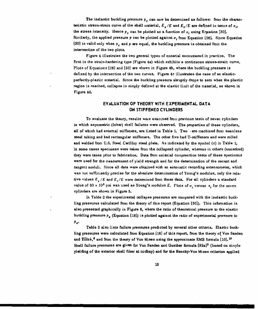
The inelastic buckling pressure p. can now be determined as follows: from the charac-
teristic stress-strain curve of the shell material, E./E and Eg/E are defined in terms of oi,
the stress intensity. Hence p, can be plotted as a function of ci using Equation [30].
Similarly, the applied pressure p can be plotted against ai from Equation [26]. Since Equation
(30] is valid only when p, and p are equal, the buckling pressure is obtained from the
intersection of the two plots.
Figure 4 illustrates the two general types of material encountered in practice. The
first is the strain-hardening type (Figure 4a) which exhibits a continuous stress-strain curve.
Plots of Equations [26] and [30] are shown in Figure 4b, where the buckling pressure isdefined by the intersection of the two curves. Figure 4c illustrates the case of an elastic-
perfectly-plastic material. Since the buckling pressure abruptly drops to zero when the plastic
region is reached, collapse is simply defined at the elastic limit of the material, as shown in
Figure 4d.
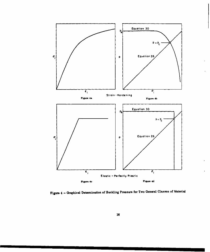
EVALUATION OF THEORY WITH EXPERIMENTAL DATAON STIFFENED CYLINDERS
To evaluate the theory, results wece examined from previous tests of seven cylinders
in which asymmetric (lobar) shell failures were observed. The properties of these cylinders,
all of which had external stiffeners, are listed in Table 1. Two *ere machined from seamless
steel tubing and had rectangular stiffeners. The other five had T-stiffeners and were rolled
and welded from U.S. Steel Carilloy steel plate. As indicated by the symbol (c) in Table 1,
in some cases specimens were taken from the collapsed cylinder, whereas in others (unmarked)
they were taken prior to fabrication. Data from uniaxial compression tests of these specimenswere used for the measurement of yield strength and for the determination of the secant and
tangent moduli. Since all data were obtained with an automatic recording extensometer, whichwas not sufficiently precise for the absolute determination of Young's modulus, only the rela.
tive values E./E and E, IE were determinod from these data. For all cylinders a standard
value of 30 x 106 psi was used as Young's modulus E. Plots of a, versus e, for the seven
cylinders are shown in Figure 5.
In Table 2 the experimental collapse pressures are compared with the inelastic buck-
ling pressures calculated from the theory of this report (Equation [30]). This information isalso presented graphically in Figure 6, where the ratio of theoretical pressure to the elastic
buckling pressure pe (Equation [16]) is plotted against the ratio of experimental pressure to
Pe"Table 2 also lists failure pressures predicted by several other criteria. Elastic buck-
ling pressures were calculated from Equation [16] of this report, from the theory o( Von Sandenand Talk6, 8 and from the theory of Von Mises using the approximate EMB formula [101.10
Shell failure pressures are given for Von Sanden and Gunther formula [92a] 9 (based on simple
yielding of the exterior shell fiber. at midbay) and for the Hencky-Von Miises criterion applied
15
Pe Equation 30 P"
U.P Equation 26
Strain -HardeningFigure 4a Figure 4b
e quofion 30
0: PC
UP Equation 26
6 a
Elastic - Perfectly Plastic
Figure 4c Figure 4d
Figure 4 - Graphical Determination of Buckling Pressure for Two General Classes of Material
16
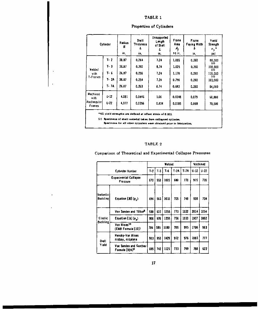
TABLE 1
Properties of Cylinders
UnsupportedIShell Lensth Frame Frame Yield
Cylinder Radius Thickness of Shell Area Faying Width StrengthR A L ,A b b yin. in. in. sq in. in. psi
T- 2 38.87 0.264 7.24 1.885 0.260 88,000(c)
T- 3 38.87 0.260 8.74 1.625 0.260 108,000Welded (c)
with T- 6 26.87 0.256 7.24 1.170 0.260 115,000T-Franes (c)
T- 2A 38.87 0.254 7.24 0.796 0.260 103,000T- 7A 26.87 0.263 8.74 0.683 0.260 84,000
Machinedwith U-J12 4.081 0.0446 1.06 0.0248 0.079 68,000
Rectangular U-22 4.077 0.0356 0.834 0.0185 0.068 70,500Frames
.All yield strength* are defined at offset strain of 0,002.
(c) Specimens of shell material taken from collapsed cylinder.Specimens for all other cylinders were obtained prior to fabrication.
TABLE 2
Comparison of Theoretical and Experimental Collapse Pressures
Welded Machined
Cyinder Number T-2 T-3 T-6 T-2A T-7A U-12 U-22
Experimental CollapsePressure 670 553 1005 680 770 975 735
InelasticBuckling Equation (30] (p,) 696 563 1016 705 748 938 734
Von Sanden and T61kee 930 631 1258 773 1032 2014 1054
Elastic Equation [16] (p.) 906 626 1259 756 1010 1907 1002Buckling Von Mises10
(EMB Formula [101) 786 585 1180 705 995 1786 963
Hencky-Von MisesShell midbay, midplane 903 953 1429 912 976 1081 777
Yield Von Sanden and GuntherFormula [92A09 695 742 1121 733 799 788 622
17
120
S100C
S80o
C
- 60
• 40Z
E 200
T- 2( T -3(c) T-6 (c)
i I I I I / I I I I I0 2000 4000 0 2000 4000 0 2000 4000 6000 8000
Strain Intensity, Ei in U/in./in.
(All Strains Corrected on Basis of Ea 30 x 106 psi)
120
"100.S
Sso-
C
60
. 40
El 2020
UT-2A T-7A U-12 U-22
0 2000 4000 0 2000 4000 0 2000 0 2000 4000Strain Intensity, e. in U/in,/in. 6
(All Strains Corrected on Basis of E - 30 x 10 psi)
Figure 5 - Compression Curves (oa Cylinder Materials
(c) Material taken from collapsed cylinder
Axis of load cothrsponds to circumferential direction in cylinder
18
t.0/. Welded
Cylinders
o Machined Cylinders
09- .
08
0.7.
08
0.6
0.5 0
0.4
0.3 0.4 0.5 0.6 0.7 0.8 0.9 1.0
Experimental Pressure /s
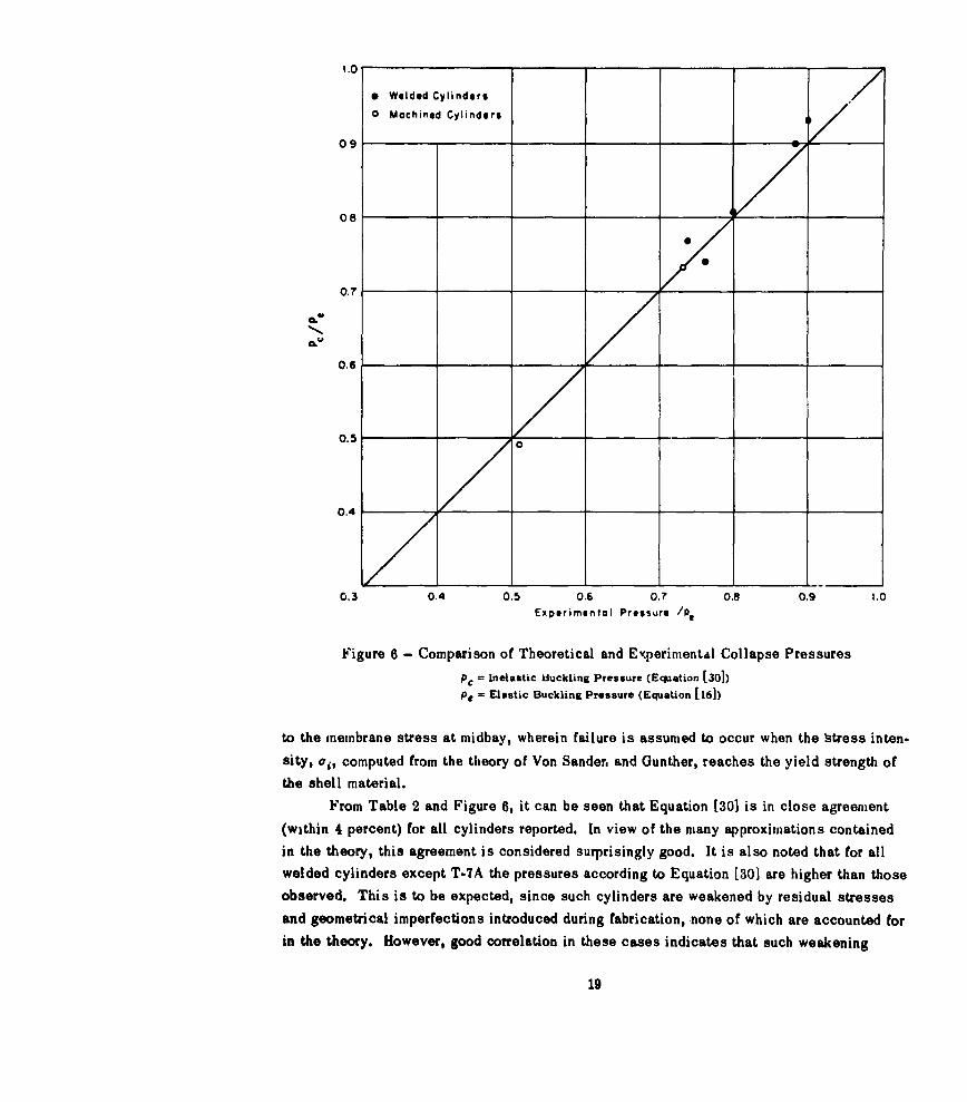
Figure 6 - Comparison of Theoretical and ExperinentAd Collapse Pressures
pc = Inelastic Buckling Pressure (Equation [30])
P e = Elastic Buckling Pressure (Equation [16])
to the membrane stress at midbay, wherein failure is assumed to occur when the Istress inten-
sity, oi, computed from the theory of Von Sander. and Gunther, reaches the yield strength of
the shell material.From Table 2 and Figure 6, it can be seen that Equation [30] is in close agreement
(within 4 percent) for all cylinders reported. In view of the many approximations contained
in the theory, this agreement is considered surprisingly good. It is also noted that for allwelded cylinders except T-7A the pressures according to Equation [30] are higher than those
observed. This is to be expected, since such cylinders are weakened by residual stresses
and geometrical imperfections introduced during fabrication, none of which are accounted for
in the theory. However, good correlation in these cases indicates that such weakening
19
effects may not be as severe as had previously been suspected. From the uniformity of the
results there also appears to be no significant difference for the limited available test results
between those cases where test specimens were taken before fabricalon and those where they
were taken from the collapsed cylinder.
CONCLUSIONS
1. The theory of this report, on the basis of the limited test data available, appears topredict the 'inelastic (lobar) buckling pressure with good accuracy.
2. Final evaluation of the theory must await additional experimental data, which should
include tests of cylinders with internal frames.
ACKNOWLEDGMENTS
This work was initiated at the suggestion of Mr. John G. Pulos and has proceeded
under his general guidance. The author is greatly indebted to Dr. Myron E. Lunchick, who
provided valuable suggestions and advice. Thanks are also due Mr. John E. Buhl, who
supplied the experimental data, and to Mr. Abner R. Willner, from whom the stress-strain
measurements were obtained.
20
APPENDIX
DERIVATION OF BUCKLING EQUATIONS
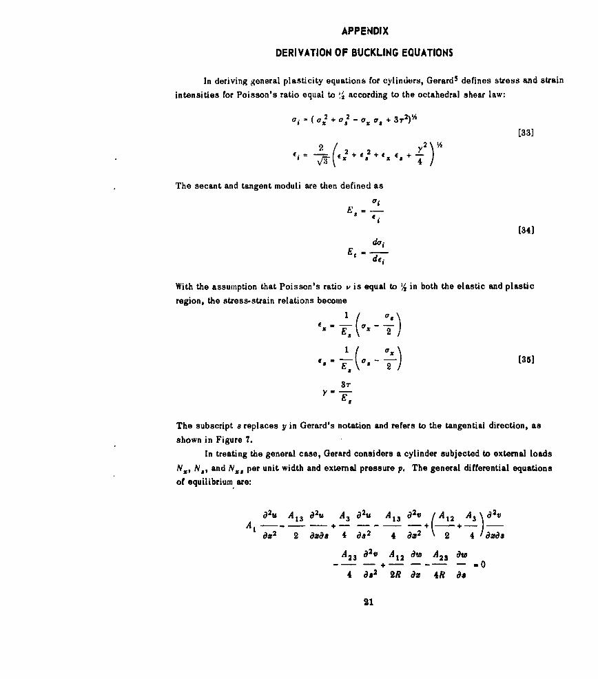
In deriving general plasticity equations for cylinders, Gerard5 defines stress and strain
intensities for Poisson's ratio equal to !' according to the octahedral shear law:
'Ii a 2 + a - a a + 3r2)%
[33]
2,- - + , 2 + ,•÷ es,+÷_
The secant and tangent moduli are then defined as
E" di
[34]di
With the assumption that Poisson's ratio v is equal to !1 in both the elastic and plastic
region, the stress-strain relations become
iF • ( 0 ,X - - a
3-rEs
The subscript a replaces y in Gerard's notation and refers to the tangential direction, as
shown in Figure 7.
In treating the general case, Gerard considers a cylinder subjected to external loads
Nx, Ns, and Nx, per unit width and external pressure p. The general differential equations
of equilibrium are:
a2u A 13 u2t, A3 a2, A13 a1 3 A A\A + -"A 22 2 dx&8 4 as 2 4 dm2 2 4 amas
A2 3 a2v A1 2 ae A2 3 aw
-- - +- -- - -04 as 2 2R am 4R as
21
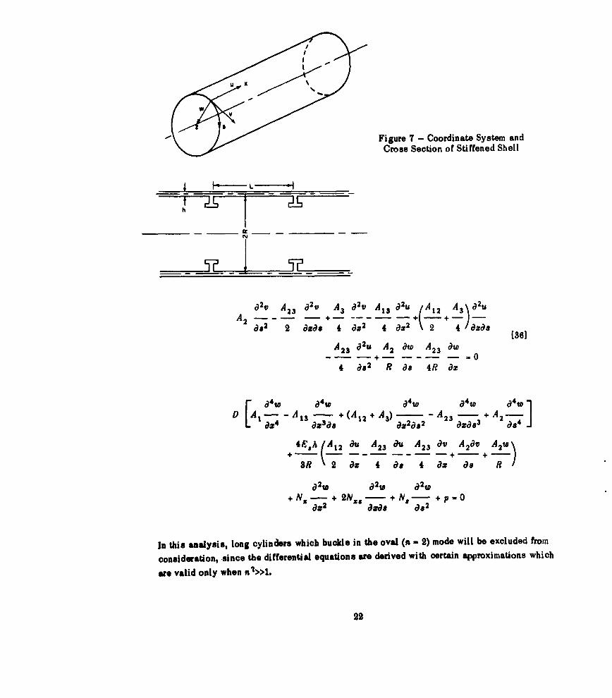
U
Figure 7 - Coordinate System andCross Section of Stiffened Shell
t _
dBvtA 2v A~t aBv 2u A A3 d2u23 A3 BtA 13 12 3A2 + +| + /-Bd2 2 aBd 4 d:2 4 dg2 \2 4 a zs [36]
A 2 3 B2u A 2 Bw A2 3 aw
I -- -- -0
4 B R2 R Ba 4R dz
FB 4tW B4 to B4 to 014 W 4w 1D A- --A 13 - + (A12 + A 3) -A 2 3 - + A 2-
I- - - -- - ---j0124 823618 dX2d82 dXza3 C184
BR 2 dz 4 d. 4 B8 Bz RI
d2W a2W a2W
+N, + 2N/ - + N 8 - +p -Oa.2 a.a. a,2
In this analysis, long cylinders which buckle in the oval (n - 2) mode will be excluded from
consideration, since the differential equations are derived with certain approximations which
are valid only when n»>>l.
22
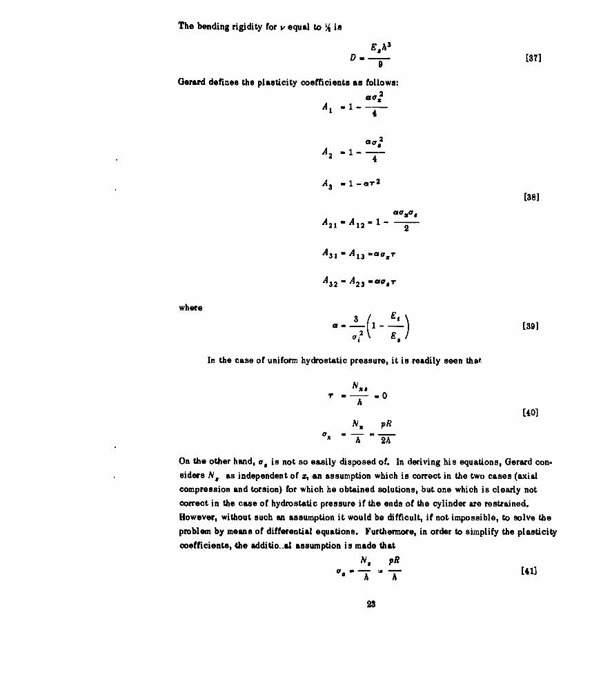
The bending rigidity for P equal to % isE, s
D -[37]9
Gerard defines the plasticity coefficients as follows:SV2
.4 -1 - --l --
A2 - 1--i-4
A3 .1 -ar2[38]
A21 '-A1 2 -1 2
A31 - A 13 m~az?
A3 2 = A2 3 =00.r
where
In the case of uniform hydrostatic pressure, it is readily seen that.
N5 #rv .. .0
A
[40]N5 pR
A 2A
On the other hand, a, is not so easily disposed of. In deriving his equations, Gerard con.siders N. as independent of x, -an assumption which is correct in the two cases (axialcompression and torsion) for which he obtained solutions, but one which is clearly notcorrect in the case of hydrostatic pressure if the ends of the cylinder are restrained.However, without such an assumption it would be difficult, if not impossible, to solve theproblem by means of differential equations. Furthermore, in order to simplify the plasticitycoefficients, the additio..al assumption is made that
NS pRao- ta. [41]
23
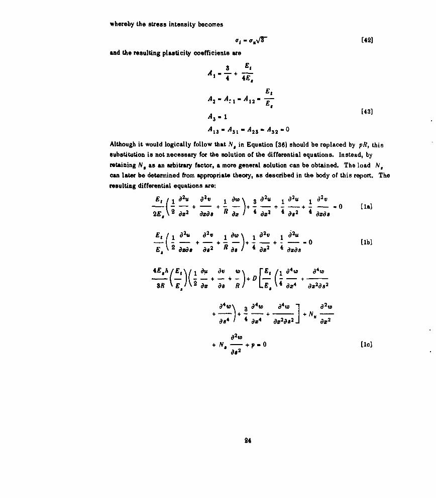
whereby the stress intensity becomes
O0 - O4' [42]
and the resulting plasticity coefficients are
8 Es
4EEt
A2 -A. - A1 2 - E-
A3 -1 [43]
A1- A 3 W- A 23 - A32 - 0
Although it would logically follow that N. in Equation [36] should be replaced by pR, this
substitution is not necessary for the solution of the differential equations. Instead, by
retaining N. as an arbitrary factor, a more general solution can be obtained. The load NS
can later be determined from appropriate theory, as described in the body of this report. The
resulting differential equations are:
Et 1 a 2 t 1 t ao\ 3 0 2u 1 a 2 U 1 0 2 VI + - - + - - + - - + - - -la
2E,\ ( 2 a2 Oza. R ax 4 8w2 4 082 4 azxa
Es 1 a2, a1 ) 182V 1 [iU
+ -- + 1 -t + + 0 [-b]Es 2 aia CS2 4 axas
ýL(-,)I - + )+D E- a + -8~
a4W a4 a4W a2W+ - + + NX -88) 4. a-4 + -- 2---&82 N
a.2
24
REFERENCES
1. Bijlaard, P.P., "Theory and Tests on the Plastic Stability of Plates and Shells,"Journal Aeronautical Science, Vol. 16, No. 9 (Sep 1949).
2. Bijls:ýrd, P.P., "On the Plastic Stability of Thin Plates and Shells," Verh. Koninklijke
Nederlandsche Akademie van Wetenschappen, Vol. L, No. 7 (Sep 1947).
3. Ilyushin, A.A., "The Elasto-plastic Stability of Plates," National Advisory Committeefor Aeronautics, Technical Memorandum 1188 (Dec 1947).
4. Stowell, E.Z., "A Unified Theory of Plastic Buckling of Columns and Plates,"
National Advisory Committee for Aeronautics Report 898 (1948).
5. Gerard, G., "Compressive and Torsional Buckling of Thin-wall Cylinders in YieldRegion," National Advisory Committee for Aeronautics Technical Note 3726 (Aug 1956).
6. Lunchick, M.E., "Plastic Axisymmetric Buckling of Ring-Stiffened Cylindrical ShellsFabricated from Strain-Hardening Materials and Subjected to External Hydrostatic Pressure,"David Taylor Model Basin Report to be published.
7. Donnell, L.ll., "Stability of thin-walled Tubes under Torsion," National AdvisoryCommittee for Aeronautics Technical Report 479 (1933).
8. Von Sanden, K. and Tblke, F., "On Stability Problems in Thin Cylindrical Shells"(aber Stabilititsprobleme Dhnner, Kreiszylindrischer Schalen), Ingenieur-Archiv, Vol. 3,
pp. 24-66 (1932), David Taylor Model Basin Translation 33 (Dec 1949).
9. Von Sanden, K. and Gunther, K., "The Strength of Cylindrical Shells, Stiffened byFrames and Bulkheads, under Uniform External Pressure on All Sides," (Uber dasFestigkeitsproblem guerversteifter Hohlzylinder unter allseitig gleichmassigem Aussendruck),Werft-Reederei-Hafen, Vol. 1 (1920), Nos. 8, 9, and 10, and Vol. 2 (1921), No. 17. SeeDavid Taylor Model Basin Translation 38 (Mar 1952).
10. Windenburg, D.F. and Trilling, C., "Collapse by Instability of Thin Cylindrical Shellsunder External Pressure," Transactions, American Society of Mechanical Engineers, Vol. 56,No. 11 (1934). Also Experimental Model Basin Report 385 (Jul 1934).
11. Salerno, V.L. and Pulos, J.G., "Stress Distribution in a Circular Cylindrical Shell
under Hydrostatic Pressure Supported by Equally Spaced Circular Ring Frames," PolytechnicInstitute of Brooklyn, Department of Aeronautical Engineering and Applied Mechanics,
Report 1T1-A (Jun 1951).
12. Lunchick, M.E. and Short, R.D., Jr., "Behavior of Cylinders with Initial Shell Deflec-tion," Journal of Applied Mechanics, Vol. 24, No. 4, pp. 559-564 (Dec 1957).
18. Gerard, G. and Wildhorn, S., "A Study Of Poisson's Ratio in the Yield Region,"National Advisory Committee for Aeronautics Technical Note 2561 (Jun 1952).
25
INITIAL DISTRIBUTION
Copies
13 CHBUSHIPS3 Tech Info Br (Code 335)1 Tech Asst (Code 106)1 Prelim Des Br (Code 420)1 Prelim Des Sec (Code 421)1 Ship Protec (Code 423)1 Hull Des Br (Code 440)2 Sci and Res Sec (Code 442)1 Struc Sec (Code 443)1 Submarine Br (Code 525)1 Hull Arr, Struc and Preserv Br
(Code 633)
2 CHONRStruc Mech (Code 439)
2 CNORes and Dev Div, Undersea WarfareSec (Op 702C)
1 CDR, USNOL
1 CO, USNROTC and USNAVADMINU MIT
1 DIR, USNRL, Attn: TID (Code 2027)
1 DIR of DEF R and E, Attn: Tech Library
2 NAVSHIPYD MARE
1 NAVSHIPYD NORVA, Attn: UERD(Code 280)
2 NAVSHIPYD PTSMH
1 SUPSHIP, Groton
1 SUPSHIP, Newport News
1 SUPSHIP, Pascagoula
1 NNS & DD CO
1 Ingalls Shipbldg Corp
1 Elec Boat Div, Gent Dyn Corp
1 0 in C, PGSCOL, Webb
1 G. Gerard, College of Engin, New York Univ,New York
97
;S1.!
ijii I t
a* d- U• ?.ll. .. u m v.... i3 i ._• I
" ~ ~ ~ - _C d ,. , '.
*; -_.d~
* i "
:
d
* IE I . 3I7 I
:j ...8 a b t. .
* .. P.. .
A I* * .j*U - '2
.! c !,
°" "!~i •"&
• .I
__ _,_ _ _ ..0__
. .: