Embed Size (px)
Citation preview

UNCLASSIFIED
AD NUMBERAD526585
CLASSIFICATION CHANGES
TO: unclassified
FROM: confidential
LIMITATION CHANGES
TO:Approved for public release, distributionunlimited
FROM:
Distribution authorized to U.S. Gov't.agencies only; Test and Evaluation; 22 JUN1973. Other requests shall be referred toOffice of Naval Research, Attn: Code 462,Arlington, VA 22217.
AUTHORITY31 Dec 1978 per GDS document marking;Office of Naval Research ltr dtd 15 Mar1979
THIS PAGE IS UNCLASSIFIED

'0 % .I HAZELTINE CORPORATIONGREENLAWN, NEW YuRK 11740
CONFIDENTIAL
Report 6165
OPERATIONS ANALYSISOF A
MULTISTATIC ECHO-RANGING SYSTEM (U)"(FINAL REPORT)
R.A. SHADEHAZELTINE CORPORATION
GREENLAWN, NEW YORK 11740
ONR CONTRACT N00014-71-C-0311TASK NUMBER NR364-043/1-29-71 462
December 1972
Reproduction in whole or part is permitted forany ourpose of the United States Government
'U NAVAL ANALYSIS PROGRAMSOFFICE OF NAVAL RESEARCH"DEPARTMENT OF THE NAVY
"Dr i i d ARLINGTON, VA., 22217
"Distribution limited to U.S. Government agencies only: Test andevaluation, 22 June 1973. Other requests for this document must
S be referred to Office of Naval Research (Code 462)."
"1"CONFIDENTIAL classified by Director, Naval Applications and AnalysisDivision, ONR, subject to General Declassification Schedule of ExecutiveOrder 11652, declassified 31 Dec 1978."
"NATIONAL SECURITY INFORMATION
"Unauthorized disclosure subject"to criminal sanctions.? I I-)0
•+ This .PiIeh h
S+~ •+ ,+ • . .. + +" ... 1 -T z- -r--T r -T+�3•54 U•e" D
T. ZThis age~ s Unlassiiedr

HAZELTINE Cr'RPORATIONGREENLAWN, NEW YORK 11740
CONFIDENTIAL
Report 6165
OPERATIONS ANALYSISOF A
MULTISTATIC ECHO-RANGING SYSTEM (U)(FINAL REPORT)
B.A. SHADEHAZELTINE CORPORATION
GREENLAWN, NEW YORK 11740
ONR CONTRACT N00014-71-C-0311TASK NUMBER NR364-043/1-29-71 462
December 1972
Reproduction in whole or part is permitted forj any purpose of the United States Government
NAVAL ANALYSIS PROGRAMSOFFICE OF NAVAL RESEARCHDEPARTMENT OF THE NAVY
ARLINGTON, VA., 22217
"Distribution limited to U.S. Government agencies only: Test andevaluation, 22 June 1973. Other requests for this document mustSbe referred to O ffice of N aval R esearch (C ode 462)."
"CONFIDENTIAL classified by Director, Naval Applications and AnalysisDivision, ONR, subject to General Declassification Schedule of ExecutiveOrder 11652, declassified 31 Dec 1978."
"rNATIONAL SECURITY INFORMATION
Unauthorized disclosure subjectto criminal sanctions."
5354 This Page is UnclassifiedCONFIDENTIAL
I
....
L,.- U

ConfidentialSecurity Cla.s~If~tcoiors
DOCUMENT CONTROL DA I A - R & D?(Security class. fic.,tion of titIle body' of irbstract and indexing Annote lion muvt be entered wrhen the ove -all report iscto- i ti-
I ORIGONArTING ACTIVITY (Car~orate author) Ua.. REPORT SEC JRITY CL ASSIFICATL ON
Hazeltine Corporation CONFIDENTIALGreenlawn, New York 11740 jb ~U
3 REPORT TITLE
OPERATIONS ANALYSIS OF A MULTISTATICECHO-RANGING SYSTEMFINAL REPORT
4 OF-SiF r.VE NOTES (Type of report and Inclusive dates)
FINALREPORT 1 June '971 .3 eebr7S. AU THOR(S) (Ftirst name, mi~ddle initial, lost name)
Robert A. Shade
S -REPORT DATE 17e. TOTAL NO. OF PAGES 17b. NO. OF REFS
D~ecember 1972 1fSe. COWNTRACT OR GRANT NO S.. OR1IGINATOR-S REPORT NUMBER(S)
N00014-71-C-0311b. PROJECT NO 66
RF 018-96-01C NR 3034-043 9b. OTHER REPORT NOM~ (Any other numbers that may be a3srgried
10. DISTRIBUTION STATEME.NT
Distribution limited to U. S. Government agencies only: Test and evaluatioin,22 June 1973. Other requests for this document must be referred to Officeof Navai Research (Code 462)
It. SUPPLEMENTARY NOTEZZ 12. SPONSORING MILITARY ACTIVITYINaval Analysis Programs (Code 462)jOffice of Naval Research1.,.ABSTACTArlington,
Virginia 22217
(C) Operations analysis of a muiti~tatic echo-ranging system consisting of the W6-2tand remote sonobuoys demonstrate- outstanding performance for scenarios of convoyscreening and target prosecutioin in the No rth Atlantic and Mediterranean.
f (C) The remote sonobuoy consists of a 6-element vertical line aryseilydrsignefto reduce reverberation effects. The receiver was designed using a unique bistaticacoustic computer program and did perform successfully at sea.(C) The scenarios assume a CZ contact, and analysis utilizing an operations analysiscomputer model developed for this project shows that three buoys are sufficient forconvoy screening and eight buoys in the Atlantic and four in the Mediterranean are sufficient for target prosecution. These buoy plan-,'. result in detection probabilities inexcess of 90% and in more than half the cases, localization is possible.(C) Highly effective ship's doctrine for ccrxvpy screening is to run a course of 450 wit
t res-pect to the target datum. For target prosecution, it is best to follow a zig-zagcourse for environments with narrow CZ's and to head directly towards the datum forr environments with wide CZ's.(C) When a layer is present the receivers are planted at 60' and when no layer ispresent 1500' receivers are deplo~red.(C) The system was found to h..ve tactical advantages and to be four times more cost-effective than a CASS system with equivalent detection performance.
DD sAovos'1473 Confidential"W1 Security Classification
-7-

UnclassifiedSccu'.,ty CtassiLfcotfnn
14LINK A LINK e LINK( C
KEY WORDS-ROLE WT ROLE WT ROLE I
J A
LIN -
-
Inlsii- SeuiyIesfctoM 4w

HAZELTiNE CORPORATION
UNCLASSIFIED
Report 6165
tI5
This work was sponsored by ONR code 462
•: and performed under its technical guidance.
I
It
1S-
|I-

S4 UNCLASSIFIEDI. Corporation
TABLE OF CONTENTS
j SECTION Page
I INTRODUCTION. . . . . . ........... 1-1jA. BACKGROUND . ............. 1-1
B.S~TUDYO0BJECTIVES................... 1-2C. REPORT ORGANIZATION .......... 1-3
II TECHNICAL ANALYSIS ............. 2-1A. OPERATIONS ANALYSIS COMPUTER MODEL 2-1B. BISTATIC ACOUSTIC MODEL . . . .. 2-4
III SYSTEM DESCRIPTIONS ... .......... 3-1IV NORTH ATLANTIC OPERATIONS ANALYSIS . . . 4-1
A. ENVIRONMENT DESCRIPTION . . . .. 4-1B. ACOUSTIC PERFORMANCE . . . . . 4-1C. CONVOY SCREENING SCENARIO . . .. 4-8D. TARGET PROSECUTION SCENARIO . . . 4-19
V MEDITERRANEAN OPERATIONS ANALYSIS . . . 5-14. ENVIRONMENT DESCRIPTION ..... 5-1B. ACOU..T.C PERFORMANCE .......... 5-3C. SCREENING IN THE MEDITERRANEAN . . 5-6D. TARGET PROSECUTION IN THE
MEDITERRANEAN . . . . . . . . . 5-10VI CONCLUSIONS AND RECOMMENDATIONS . . . . 6-1
I APPENDIKES
j A. RESULTS OF CCMPUTER RUNS
B. SURFACE ROUGHNESS: INFLUENCE ON PROPAGATIONJ LOSS
C. DISTRIBUTION LIST AND FORM 1473
6165 i
UNCLASSIFIED

Hazelfine UNCLASSIFIED.. poWation
LIST OF ILLUSTRATIONS
Figure Page
4-1 Coverage of 41-.X Sonobuoy Used with SWS-26 inBB/ODT Transmit Mode(Predicted with Isovelocity Ray Tracing) .4... . -3
4-2 Coverage of 41-X Sonobuoy Used with SQS-26 inBB/TRACK Transmit ModeTPredicted with Isovelocity Ray Tracing) . ..... 4-4
4-5 Coverage of 4]-X Sonobuoy Used with SQS-26 inBB/ODT Transmit Mode . . . . . . . . . 4-5
4-4 Coverage of 41-X Sonobuoy; Target in Layer . .... 4-64-5 Coverage of the CASS Buoy . . . . . . . * . 4-74-6 Convoy Screening Scenario - Target Heading 180
Datum at 00 . . . . . . . 4-104-7 Convoy Screening Scenario - Target Heading 180
Datum at 30 . ...... .... . .. 0 4-114-8 Convoy Screening Scenario - Target Heading 180
Datum at 60 . . *. . . . . . . . .. .. 4-124-9 Individual Receiver Performance in Convoy
Screening Scenario . . . . . . . . . . 4-134-10 Convoy Screening Scenario - Target Course CPA;
Ship Course0 .* . * ' * ...... ...... 4-154-11 Convoy Screenwg Scenario - Target Course CPA;
Ship Course4z . . .. ... ..... 4-164-12 Convoy Screenilg Scenario - Target Course CPA;
SLtp Course 90 . . . . . . . .... .. 4-174-13 Individual Receiver Performance in Convoy Screening
Scenario . . . . . . . . . . . . . . . . . 4-184-14 Advancing Barrier for Convoy Screening . . . . . . 4-234-15 Target Prosecution in North Atlantic; 6 Buoy Plant . . . 4-224-16 Target Prosecution in North Atlantic; 8 Buoy Plant . . . 4-234-17 Target P-rosecution in North Atlantic; 3 Rocket-
Launched Buoys . . . . . . . . . . . . . . . 4-254-18 Scenario for Anti-SLBN Analysis in North Atlantic . . . 4-274-19 Mission Effectiveness for Anti-SLBN Analysis . . . . . 4-284-20 CASS Systefm for Target Prosecution in North Atlantic . . 4-295-1 Coverage of 41-X Sonobuoy; Mediterranean with
Surface Duct; Receiver at 60 .0. . . .... . 5-45-2 Coverage of 41-X Sonobuoy: Mediterranean with No
burface Duct; Receiver at 60' .......... 5-55-3 Coverage of 41-X Sonobuoy; Mediterranean with no Surface
Duct; Receiver at 1500' . . .. a.. ..... 5-75-4 Comparison of SQS-26 and SQS-23 Monostatic Coverage . 5-85-5 Coverage of 41-X Sonobuoy in Mediterranean Using
SQS-23 Transmitter . ........ . . . . 5-9
6165 ii
UNCLASSIFIED

C a •UNCLASSIFIEDi Con~atn
LIST OF ILLUSTRATIONS (Cont'd)
Figure Page
5-6 Target Prosecution in Mediterranean; 6 Buoy Plant;Target Below Layer; Receivers at 1500' . . . . . . 5-11
5-7 Target Prosecution in Mediterranean; 4 Buoy Plant;Target Below Layer; Receivers at 60' . . . . . . . 5-12
5-8 Target Prosecution in Mediterranean; 4 Buoy Plant;Target Below Layer; Receivers at 1500' . . . . . . . 5-13
5-9 Target Prosecution in Mediterranean; 4 Buoy Plmat;S Target in Layer; Receivers at 60' ........ 5-14
5-10 Target Prosecution in Mediterranean; 4 Buoy Plant;Target in Layer; Receivers at 1500 ' . ..... . . . 5-15
S5-11 Target Prosecution in Mediterranean; 4 Buoy Plant;No Layer Present; Target at 55'; Receivers at 60' . . 5-16
5-12 Target Prosecution in Mediterranean; 4 Buoy Plant;No Layer Present; Target at 55' Receivers at 1500' . . 5-17
5-13 Target Prosecution in Mediterranean; 4 Buoy Plant;No Layer Present; Target ac 300'; Receivers at 60' . . 5;.18
5-14 Target Prosecution in Mediterranean; 4 Buoy Plant;,No Layer Present; Target at 300'; Receivers at 1500' . . 5-19
5-15 Target Prosecution in Mediterranean Using Second CZ . . 5-20
I
6165 iiiUNCLASSIFIED
S...-i W

z UNCLASSIFIEDCorporation
FOREWORD
The following naval activities provided assistance in the formulation ofthe problem:
J. Jagadzinski for discussion of helicopter parameters, Naval Air De-velopment Center, Johnsville, Pennsylvania;
The personnel at DESDEVGRUTWO, and especially STCS E. J. A Spoon-amor e.
This work was sponsored by ONR Code 462 and performed under the tech-nical guidance of R. Dickman of that office. We gratefully acknowledgehis assistance during the contract and especially in the preparation ofthis report.
Acknowledgement is also made of the assistance given by Hazeltinp per-sonnel: T. DeFilippis, S. Ginsberg, and especially A. Novick foy histechnical guidance throughout this project.
I
6165iv
UNCLASSIFIED
... UP-, .. =

CON FIDE NTAL
Copowaton SUMMARY
C) Operations analysis of a multistatic sonar system consisting of anS9QS-26 and remote sonobuoys indicates that outstanding performancecan be expected for screening and target prosecution scenarios in bothNorth Atlantic and Mediterranean environments. Consistently hightarget detection probabilities were obtained in all scenarios by theproper utilization of the system including buoy placement and ship'sdoctrine. Comparison with a CASS syotem which can achieve the sameperformance shows that the multistatic system has a four-to-one costeffectiveness advantage and a tactical advantage due to the absence of anearby actively pinging transmitter.
S(C) Recommended tactical doctrines are as follows. For environments"in which the convergence zone (CZ) is narrow (- to 5 kyds) a 45 0 courseaway from the datum for approximately 30 minutes followed by a 900
jturni towards the datum with a ship speed of 15 knots is recommended.This results in a Plow advancement of the CZ over the target uncertaintyarea and will provide the sonar with more "looks" at the target. For en-vironments with a broad CZ. the ship should proveed directly at the datumagain resulting in maximum use of the CZ coverage. Best receiverdepths are 601 for environments with a layer and 1500' for environments
f with no layer.(C) The sonar system consists of an SQS-26 operating in the bottom bounce
search mode. 0In thies mode, it uses three sequential 400 transmissionsto cover a 120 azin.,.tial sector. This sonar uses 12 contiguous pre-formed beams to receive possible echoes. The remote bistatic receiverconsists of a six element vertical line array of omnidirectional elementsspaced approximately one foot apart, deployed at depths of 60 ft or 1500ft. This type of array was designed to reduce reverberation effects anddid perform successfully at sea.
(U) The study was aided by the use of two computer programs: (1) An opera-tions analysis model used to calculate target detection probabilities aW theexercise progressed with time: (2) A bistatic acoustic model uced to pre-dict buoy coverage, calculate propagation losses, and create tables of re-verberation as a function of time.
(U) The study consisted of a number of exercises in various environments"and scenarios. Key results of these studies are summarized below.
1. Convoy Screening in the North Atlantic
(C) This involved the problem of redetecting a target which was initially de-tected in the convergence zone at a range of about 70 kyds and subsequently
6165
vCONFIDENTIAL
II

CONFIDENTIAL
HazehrnCorporation
lost. It is assumed that the submarine is a&tempting to penetrate a de-stroyer picket to attack a high value unit. An azimuthal uncertainty of +50is assumed in the initial target datum and the cumulative probabilities ofdetection for various target tracks are calculated spanning this uncertaintyand for various target tactics.
(C) Following the initial target datum by a delay of about 10 minutes, a heli-copter is iaunched to drop several remote sonobuoys in the vicinity of thedatum. The set of drop points for these rec wivers was one of the paramet-ers which was determined during this study.
(C) The final results show that the use of as few as three properly placedsonobuoys plus the shipboard sonar combined with a ship's doctrine ofturning to an angle of 450 away from the target datum virtually ensureredetection -f the target if it attempts to penetrate the screen. Cumu-lative probabilities of detection approaching unity were obtained con-sistently for either submarina tactic and for submarine speeds between6-15 knots. A submarine moving faster than 15 knots should be detectedpassively by tha sonobuoys.
2. Target Prosecution in the North Atlantic
(C) In this study, the initial datum and the system used are the same asdescribed above, however, the target may follow a course in any direc-tion. The goal of the ship was to redetect the submarine, with a latergoal of localization and weapons drop,
(C) Analysis shows that CZ contact investigation for an SLBN submarine al-ways results in near unity detection probabilities because of the high tar-get strength. For other types of contacts redetection is 80-90 percentassured over a target uncertainty area of about 700 square nm (a radiusof 15 nm) by using 8 sonobuoys laid down in a pattern similar to that ona playing card and using a ship's doctrine of closing directly at the datum.
(C) For a conventional .,ibmarine, after a CZ contact the probability of re-detection is over 9U percent for a field of 8 sonobu',ys plus the SQS-26.The best tactical doetrine here is to pl'tt the ,uoys along the spiral pre-dicted by the time late of the helicopter and fcc the ship to run a zig-zagtrack of 450 away from the datum for abc"-. jO minutes and then turn 909
towards the datum and proceed.
(C) To examine the importance of time late on multistatic doctrine, a seriesof runs was made assuming rocket launched sonobuoys with delivery speedof about 1400 knots: The results show that because ot the greatly reduceduncertainty area, 2 rocket launched buoys perform as well as 8 helicopterlaunched buoys. Best ship's doctrine in this case is to slow down to 6-J 0knots and head straight at the datum.
6165 CONFIDENTIAL
j77_

'CONNFIDENTiALS~Hazerdre
Cormoration
(C) Finally, tor the same Pnvironment and scenario, a comparison was madebetween multistatics and (CASS. The results show that about twice asmany bistatic buoys as CASS buoys are required to achieve the samemission effectiveness. This implies about a four times greater costeffectiveness for bistatics. In ,.ddition, bistatics has a tactical advan-tage over CASS in that the target can more easily avoid detection by aCASS buoy if it readjusts its track accord .ng to the location of this
I actively pinging buoy.
3. Target Prosecution in the Mediterranean
(C) The system was the same as described above. Because the CZ in theMediterranean occurs at about half the range of i 't in the Atlantic, tar-
Sget prosecution was achieved with near unity detection probabilities re-i gardless of target depth or layer depth. T is was accomplished using
only 4 sonobuoys plus the SQS-26 ancl a ship's doctrine of heading di-rectly at the datum at a speed of 15 knots.
(C) Results show that replacing the SQS-26 by an SQS-23 will roiult in some-what reduced echo-to-background levels but will still perform quite wellin a multistatic operation in this environment.
(C) In all of the cases run, it appears that by intelligent operation of the -tem, there is a reasonable probability (about 50 -ercent in the North At-lantic and higher in the Mediterranean) of detecting the target simultan-
jeously with at least two receivers and tnus localization might also beachieved. This probability can of course be increased by deployingmore remote sonobuoys.
4. Conclusions
t (C) The results of this study substantiate that this multistatic approach sig-nificantly increases operational effectiveness for these scenarios when com-pared with presently used systems. It is clear that multistatic systemsoffer a highly useful adjunct to the Navy's erlsting sonar capabilities andthus merit further investigations both analytical and expet-imental.
:~ 1 6165_C~ONFIDENTIAL

CONFIDENTIAL
HazefireCorpoation
LIST OF ABBREVIATIONS
AMOS - Acoustical, Meteorological, and Oceanographic Survey
BB - Bottom bounce
BB/ODT - Transmitter mode using 1200 sector formed from threecontiguous 400 beams
BB/TRACK - Transmitter mode utilizing a 400 beam (SQS-26-BX)or 100 beam SQS.-26-AX and SS-26-CX
BTM - Bottom
CASS - Command Active Sonobuoy System (A seli-containedXmtr/Rcvr)
CPA Clcsest point of approach
CPD - Cumulative Probability of Detection
CZ - Converpence Zone
DP - Direct Path
DSL - Deep scattering layer
E/7 - Echo-to-background ratio in dB
LFM - Linear FM
MAD - Magnetic anomaly detector
MGS - Marine Geological Survey
MTA - Minimum target aspect
NM - Nautical Mile
RCVR - Receiver
SL - Source level
SLBN - Nuclear missile launching submarine
VLA - Vertical Line Array
XMrR - Transmitter
41-X - 6-element vertical line array used as buoy in this study
Viii6165 CONFIDENTIAL
S.. . . - ' , ) . a • • • . .. , , - . . -_. . .. . . _ • • -. f ij . .••

CONFIDENTIAL
HazeflbneCorporation
SECTION I (C)
INTRODUCTION
A. BACKGROUND
(C) In 1969, the technical feasibility of bistatic echo-ranging with the SQS-26transmitter and specially desiraed A-size sonobuoy-type receivers wasdemonstrated.1 The system concept is illustrated below. The receiverdesign was based on a unique bistatic analysis computer program.2
........................ " * •-••.. -- •.. •*•:•'""".. .:" :'+'":
( C) The experiment was conducted during the period 1-3 October 1969 in anarea 300 miles west of Bermuda. Average water depth in this area isS18, 000 ft. The bottom ranges from MGS Class 2 (good) to Class 4 (poor)for bottom-bounce operation. Sea State was 2 to 3. Moderate to good sur-face ducts 125 to 170 ft deep existed.
(C) This sea experiment was highly successful from several points of view.
(1) Bistatic detections were achieved at transmitter-to-targetranges of 5 to 40 kyd, and at 76 !.-yd ir 'he first convergencezone. For the target at periscope depth, maximum target-
to-receiver ranges were 5 to 11 kyd. With a below-layer
1 Project D/S 510, "Bistatic Echo Raxiging Experiment," Final Tech-nical Report, Hazeltine Corporation, Report 7914, July 1970.
2 "Operations Analysis of Multistatic Echo-Ranging System," App. A,r Interim Report, Hazeltinm Corporation, Report 7984, March 1972.
6515 1-1
• __ -- CONFIDENTIALS,,== II1
ai . • ,.a

CONFIDENTIAL
HazelineCorporation
target, maximum target-to-receiver ranges were up to8. 7 kyds. (These detection ranges are in good agree -
ment with values predicted with tne acoustic model inthis environment. )
(2) Tests with an omnidirectional receiver showed the stronginfluence which reverberation has on multistatic sonarperformance and pointed out the need to reduce these ef-fects by proper hardware design.
(3) Test results showed how effective the newly designeddirectional sonobuoy was at suppressing the effect ofthis reverheration.
(4) The reverberatior, levels mez.sured were in good agree-ment with leve. s predicted in advaice using the bistaticnroustic corrputer program developed at Hazeltine.This agreement add., support to the validity of this pro-gram.
B. STUDY OBJECTIVES
(U) Once technical feasibiiity of this bistatic echo-ranging system was dem-onstrated, the next logical step was to determine the potential benefitsof such a system to the Navy. The goals of the present project were to:(1) determine the effectiveness of multistatic sonar systems in severaloperational environments; and (2) recommend ship's doctrines to bestutilize these systems. (For convenience, this bistatic sonobuoy whichis similar to the SSQ-41 is designated SSQ-41-X in this report.) Otherobjectives of this study were to compare the effectiveness of this SQS-26/41-X multistatic system with (1) CASS, and (2) a multistatic systemusing the SQS-23 and remote sonobuoys.
(U) All of the scenarios analyzed in this paper are contact investigations andthis study concentrates on two applications of the system: convoy screen-ing and target prosecution.
(U) The first of these, convoy screening, involves a submarine attempting toattack a high value unit. The goal of the destroyer escort is to providea screen with sufficient performance to detect any submarine attemptingpenetration.
(U) Target prosecution requires the destroyer to redetect and ultimately lo-calize a submarine which has been alerted to the presence of the ship andis attempting to avoid detection.
6165 1-2"CONFIDENTIAL] •-• . . . .. . . . . .• - • - _ _ . • T : :'• : • -- -. - - • • = . . .. . . . - . . r -- . . . . - - -
"CONFIDENTIAL
HazeiineCoaroatic-
(C) Two environments are considered for these scenarios: the North At-lantic and the Mediterranean Sea. Detections against both conventionaland SLBN submarines were studied.
C. REPORT ORGANIZATION
(C) The remainder of this report is organized as follows: Section II givesa description of the technical approach used in this study and a briefdescription of the computer models used in the analysis. Section IIIdescribes the sonar equipments used in the operations analysis. Sec-tion IV presents the results for the analyses conducted in the NorthAtlantic; it includes the effects of time late on system performanceand quantitative comparison with CASS. Section V describes the targetprosecutions studies for several Mediterranean environments. Sec-tion VI summarizes the conclusions and recommendations of this study.Key figures showing detection results for various cases arc included inthe main body of this report. A complete summary of all computer runsis contained in Appendix A.
(U) This document is the final report of a study performed for the Officeof Naval Research (Code 462) under ONR Contract N00014-7 1-C-0331.A comprehensive report of the work performed up to March 1972 isdescribed in an Interim Report*; topics which are covered in detailin that report are only summarized in this report. Thus, althoughthis document includes all work performed under the contract, somereferences to the Interim Report will be found in the present -report.
*Referenced in the Study Summary.
6165 1-3
CONFIDENTIAL 7n I•i7•T2-c ,•,, -.

CONFIDENTIAL
H eitneGcworation
SECTION II (C)
TECHNICAL ANALYSIS
(U) The method used in this project was to carry out an idealized systematicoperations ana.lysis to determine the comparative performance of mono-static and multistatic systems as a function of ship's doctrine, numberof sonobuoys employed, submarir e tactics (including course, speed,depth), and environment.
(U) Because of the complexity and large amount of data involved in carryingout such a task, an operations analysis computer model was writtenwhich proved to be an effective tool for comparing systems performanceas the above variables were changed.
(C) Hazeltine had previously developed a unique computer program to calculateecho-to-background ratios for bistatic receivers in the presence of re-verberation; computations using this program have been proved to bein good agreement with the experiment. In writing the present opera-tions analysis computer model, full use has been taken of the contentsand results of this program. (It was shown in the sea experiment thatreverberation provides a limiting background for the bistatic receiversand, therefore, must be included in any accurate analysis.
(U) This stction briefly describes these two models. (Additional detailsmay be found in Appendices A and B of the Interim Report.)
A. OPERATIONS ANALYSIS COMPUTER MODEL
(U) The objective of this study project was to provide a quantitative evalua-tion of a multistatic sonar system concept. In order to accomplish this,it was required that the results of submarine detection schemes beanalyzed. This requires knowledge of the probability of detection of atarget as a function of time as both the target and the ship maneuverin the water. The first part of this project was devoted to developinga sophisticated computer model which could carry out calculations in-volving such complex systems as described above. The result of thiseffort was a versatile and efficient computer model which has been giventhe name SOBER (Study of Operational Bistatic Echo-Ranging).
(U) The fundamental process which the program models is a continuous cyclerepresenting a real world time-developing physical system; actions re-sult in new information which is used to make decisions which result in new
6165 CON I1NTIAL

Haztone UNCLASSIFIEDCorpoation
actions. The rules A hich govern the system are as follows: actions areconstrained by physical laws; information is governed by environmentand obtained by means of sensors; and decisions are based on interpreta-tion of information and mission objectives.
(U) A computer model which included the full implications of this cycle wouldbe a simulation program. At present, only the action- information partsof the cycle have been programmed, deferring the addition of dynamic de-cision routines until a later date, if so desired.
(U) At the onset of this study, it was decided that the program should be capableof handling multiple units of all types. It rapidly became apparent, however,that such a program could require excessive amounts of computer memorysturage unless it was carefully organized to avoid such problems. In orderto create such a program which was both versatile and efficient, use wasmade of a concept which is called Unit Space. This techuique gives acentral role to a vehicle and then describes the environment of that ve-hicle in terms of its physical status and information acquired by its sen-sors. The importance of such a concept is that the vehicle and its en-vironment can be described and stored independently of other vehicles.This allows the computer program to handle large numbers of vehiclessince the data for each can be handled separately while all others are leftin storage outside the central memory.
(U) The computer model uses a fixed time step and consists of (1) dynamicsroutines to move the various vehicles around in time according to prede-termined tactics, (2) acoustic routines used to calculate the sound levelat each target and receiver, and (3) detection routines used to calculatethe probability of detection of the target at each receiver during each timestep and the cumulative probability of detection for each receiver.
(U) The program includes the effects of radiated noise and specular inter-ference carried out to paths involving 0, 1, and 2 bottom contacts. Theinputs to the program consist of vehicle parameters such as speed, turnrate, tactics, etc. ; equipment parameters such as sonar source level,transducer spacings, etc., and acoustical data. In the first exercises(convoy screening) the propagation losses were calculated in the opera-tions analysis model using isovelocity ray tracing. For the remainder ofthe project, all propagation losses for each system and environment wereinput to the model in the form of tables calculated using the bistatic acous-tic program and corrected for shadow zone propagation. Reverberationtables were also calculated with the bistatic program and put into themodel via tables, although experimental data could be used if desired.
"6165 2-2UNCLASSIFIED
I -

UNCLASSIFIEDCorpoaton
(U) Each exercise was set up by specifying the ship and target courscs,speeds and initial locations. A fixed time step was used during whicheach vehicle would move (a helicopter is used to deliver the buoys todrop points assigned during input), and all acoustic signals would betransmitted, received and processed according to their uccurrence dur-ing that time period. This ýnformation was used to calculate the probabilityof detection for that ping and the cumulative probability of detection (CPD)up to that time for each receiver.
(U) The expression used to calculate the single ping probability of detection
is:
exp ((-2. 3 log, 0 (Pf) - 0. 327)/(1 + SNR))
where P is the probability of false alarm (typically 10 ) and SNR is theecho-to-gackground power ratio. This result was derived by Marcum andSwerling and reported in "Transactions of the iRE," Vol IT-6, No. 2(April 1960).
(U) The calculation of cumulative probability of detection which satisfies arule such as M detections out of N when the total number of looks isgreater than N has been solved and is incorporated in the present model.
(U) A target strength function which is dependent on target aspect is used andit is of the form of 10 + 10 sin2 (fB) where B is the target aspect de-fined for bistatic receivers as shown below. (The importance of targetaspect is seen in the results of the analysis.) For an SLBN submarine,the expression used is 13 + 12 sin2 (9 B)
Transmitter
B 2"(R +T
Receiver
6165 2-3UNCLASSIFIED
C -~ ~-

CONNFDENTIAL
HazeimneCorporation
(U) The output of the program consists of a summary of input data, a trackhistory of vehicle locations, a summary of receiver locations, a chron-ological summary of detection probabilities and other pertinent data foreach receiver at each time step, a mission effectiveness summary, andprinter plots of the vehicle tracks also showing the sonobuoy locations.For purposes of efficiency, many of these outputs can be suppressed ifdesired.
(C) Certain assumptions must be made in any study of tCiis type. These as-sumptions are of the following types: (1) all equipment is assumed tooperate as designed; no system malfunctions have been included as pro-gram input; (2) human factors have been programmed based on idealoperator responses; no out-of-the-ordinary operator problems havebeen included; (3) the ocean is assumed to be describable by themathematical model discussed below.
B. BISTATIC ACOUSTIC MODEL
(U) The bistatic acoustic model is used to calculate echo-to-backgroundratios in the presence of reverberation for fixed transmitter-receiverseparation and a grid of target locations around the receiver. The workdone up to the interim report used a model based on isovelocity ray-tracingwith angular corrections made at the ray point ends to account for re-fraction. In the second phase of this study a detailed ray trace modelwas used. The outputs of these models have been shown to be consistentand do agree with data measured at sea.
(U) Tables of reverneration as a function of time of arrival at the receiverare also printed out for later use. The actual calculation of reverbera-tion for a given time is carried out by summing the contributions from thesurface, the bottom, and the deep scattering layer each of which is theresult of an integration around an eliptical annulus representing equaltime length paths from the transmitter to the scatterer to the receiver.These calculations can be carried out to include any number of specularbottom and surface contacts as well as the scattering contact.
(U) In the first part of the contract, for targets below the layer and trans-mitters and receivers in the layer, AMOS propagation losses were used.Later wher, it was desired to run cases involving either deep directional:eceivers or deep targets, it was felt that the AMOS data would not beapplicable. For this reason, the pure ray-trace program was used. This,however, predicts no energy in the shadow zone for a receiver in the layerand a target below the layer at a range greater than 3-4 kyds.
6165 2-4CONFIDENTIAL

•uie UNCLASSIFIEDCorporation
(U) To solve this problem, a short study was undertaken to develop methodsof calculating energy arriving in the shadow zone. (This study is describedin detail in Appendix B.) This study was based on work performed for theNavy by Schweitzer 1 , Medwin2 , and Nobel 3 and resulted in predictions ofenergy arriving into the shadow zone by rmeans of surface scattering (in-cluding effects of bubble phenomena) and diffraction. This model appliesto directional as well as omni arrays md is thus not reciprocal in casessuch as a deep directional array and an in-layer target. The validity ofthe model is based on agreement with AMOS data in cases where AMOSholds.
1 B. J. Schweitzer, "Sound Scattering into the Shadow Zone below anIsothermal Layet," Jourr al of the Acoustical Society of America,Vol. 44, No. 2 (1968),
2 H. Medwin, "The Rough Surface and Bubble Effect on Sound Proga-gation in a Surface Duct," 28th Navy Symposium on UnderwaterAcoustics, Vol. 1, 1N, 17-18, 1970) (CONFIDEN'TIAL)
V v"l. J. Mnhle. "Theory of the Shadow Zone Diffraction of UnderwaterSound," Journal of the Acuus•tica! Rocietv of America, Vol. 28, No. 6(1956).
f4
6165 2-5UNCLASSIFIED
-6ý

CONFIDENTIAL
oton SECTION II (C)
SYSTEMS DESCRIPTIONS
(U) In this study several different systems have been analyzed and there-fore for the sake of cot, iseness and ease of reference, all of the systemsand their parameters will be described in the four tables following.
SQ S- 2
(C) Function: Monostatic system and transmitter for
bistatic buoys
No. of Elements:
Horizontal: 20 (Cylindrical array simulated byVertical: 8 planar configurations of equal
beamwidth)
Element Spacing (ft):
Horizontal: .611Vcrtical: .695
Element Shading: Uniform
Operational Mode: Bottom Bounce and Convergence Zuiie(1200 Sector Insonification)
Source Level (dB).* 136 (BB/ODT); 142 (BB/TRACK)
Frequency (Hz): 3500
Pulse Length (ms): 500
Bandwidth (Hz): 100
Pulse Type: LFM
FM Process -
ing Gain (dB): 17
* measured relative to 1 MB at 1 yd.
6165 3-1
CONFIDENTIAL
4i n Z

CONFIDENTIAL
HazelineCorration
41-X (Bistatlc Sonoebuoy)
(C)
Function: Bistatic and Passive Receiver
No. of ElementsHorizontal: 1Vertical: 6
Element Spacing (ff)Hlorizontal: --Vertical: 1.05
Element Shading: Trizonal
Operational Mode: Direct Path
Signal Processing: (Bistatie processor is matched totransmitter waveform.)
CASS
(C)Function: Monostatic Buoy
No. of ElementsHorizontal: 1ver'Lca!:- 6
Element Spacing (ft)Horizontal: -Vertical: 0.256
Element Shading: Uniform
Operational Mode: Direct Path - Omnidirectional Transmission
Source Leve! (dB): 107
Frequency (Hz): 6500
Pulse Length (ms): 1000
Bandwidth (Hz): 400
Signal ProcessingGain (dB): 26
Only FM 'performance was coniddered.
6165 3-2
CONFIDENTIAL
IIN

CONFIDENTIAL
HazewneCooation
SW.S-23
(C) Function: Monostatic System and Transmitter for
Bistatic Buoys
No. of Elements
Horizontal: 20Vertical: 8
Element Spacing (ft)
Horizontal: 0. 428Vertical: 0. 487
Element Shading: Uniform
Operational Mode: Direct Path and Convergence Zone
Source Level (dB):* 133
Frequency (Hz): 5000
Pulse Length (ms): 30
Bandwidth (Hz): 320
Signal ProcessingGain (dB): 9 (incoherent processing)
* measured relative to 1 AB a,. 1 yd.
t
SO6165 3-3CONFIDENTIAL
.~~~~~~.~ .

UNCLASSIFIEDCorporatio
SECTION IV (C)
NORTH ATLANTIC OPERATIONS ANALYSIS
A. FNVTRONMENT DESCRIPTION
(U) The environment studied is typical of early or late summer (night), andnas the following parameters:
Water Depth 15, 000 ftIsothermal Layer Depth 150 ftDeep Scattering Layer Depth 600 ftDeep Scattering Layer Coefficieit -50 dBBottom Scattering Coefficient -27 dBWind Speed 13 knotsSea State 3MGS Bottom Class 3
490 4950 5090 _550
Velocity Profile
Depth Velocity Gradient(ft) (ft/second) (ft/second/ft)
0.0 5024.0.2 .0200 00
150.0 5027.0-. 1667
300.0 5002.0 0o
-. 0059 (f)1310.0 4996.0
-. 0533 sooo3000,0 4906.0
-. 00624600.0 4896.0 ,10000
.01206600.0 4920.0
.015512015000.0 5050.0 .Oo
B. ACOUSTIC PERFORMANCE
(U) In order to make reasonably accurate estimates of optimum buoy loca-tions for operations analysis exercises, it is useful to plot the coverageof these receivers under varying conditions. The following figures
f 6165 4-1UNC F.ASSIFIDm !a'lm-ni-n-Zun= ']

CONFIDENTIAL
HazerineCorporat.on
will illustrate some typical coverages although it should be Uorne inmind that these coverages will vary somewhat with bistatic separation,Pd target strength.
(C) Figure 4-1 shows the coverage of a bistatic receiver as predicted by theearlier version of the bistatic acoustic model. In all of these figures,the shaded area represents the area of coverage occluded by the firstbottom bounce specular arrival. This figure rind all but the followingfigure represent coverage corresponding to ; 1200 sector insonif'cationcentered on the buoy. This represents a somewhat pessimistic coveragefor contact investigation since the SQS-26 (BX) actually can operate with a400 beam in the BB/TRACK mode. For comparison, figure 4-2 showsthe same buoy using this narrower beam. In the BB/TRACK mode of theSQS-26 (CX) and (AX) a 100 transmit beam is used; this results in anarea of coverage increased over the 400 and 1200 beams due to increasedsource level and decreased off axis reverberation contributions.
(C) Figure 4-3 shows the coverage of the same buoy and conditions as figure 4-1,as predicted by the detailed ray tracing bistatic program including shadowzone propagation when it exists. Note that the coverage is quite similarexcept for a slight lateral broadening.
(C) During the first phase of this contract propagation losses were calculatedusing AMOS data. These data indicated a rapidly decreasing buoy coveragefor a 60' receiver as the target went deeper. (A 50% decrease in coveragewas found when the target went from 250' to 400'. ) Coverages as pre-dicted by the detailed ray tracing model with shadow zone propagationlosses indicate that this is not true. Only slight differences in coveragewere found as the target went to depths as deep as 1200'.
(C) Figure 4-4 shows the large increase in coverage observed if the targetmoves up into the layer.
(C) As a resuit of these coverages, it was found best to deploy the bistaticreceivers at a depth of 60' in the North Atlantic when a layer is present.If there is no surface duct, then it is belter to use these receivers at1500' because of the decfdnd-raýy pith cierage...
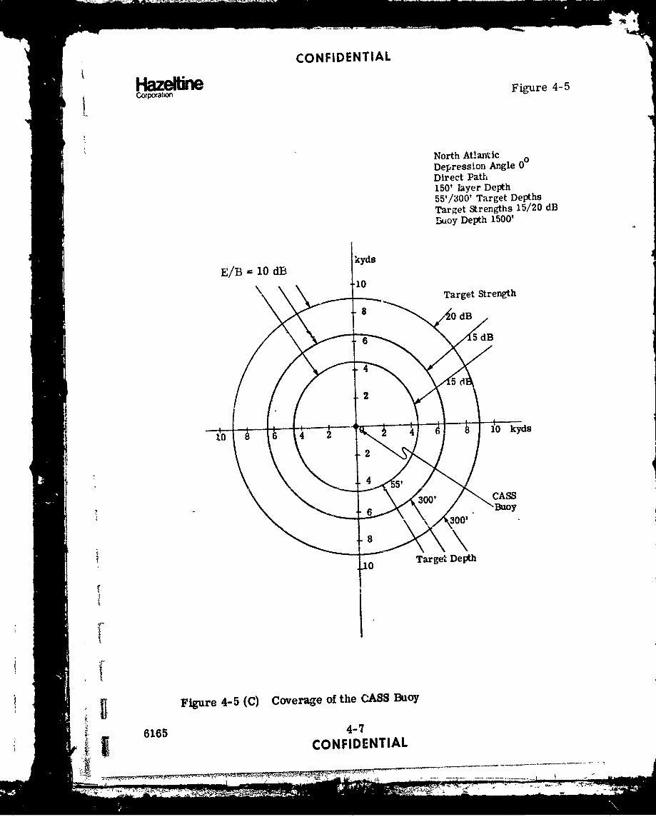
(C) Figure 4-5 shows the coverage of a CASS buoy in the 3ame environmentshowing the effects of varying target depth and target strength. The CASSbuoy at 60' does not perform as well as at 1500' as will be seen later in thefigures showing the results of the operations analysis computer runs.
6165 4-2CONFIDENTIAL
- - -..--~~---.-. . nnn-~-mni mnnS..... .. ... .. n> nu n u in n nI n I

CONFIDENTIAL
HC.raotf Figure 4-1
12
7 kyd
E/B dB
•,/ Io10 odB 16\
,6i~7V /4
21
S"• Bistatic
Receiver
: T-6
"-8Depression Angle 100BB/ODT150' Layer Depth 10250' Target DepthS200 Sector Insonification j1
{,. i12
-45
Xmtr
Figure 4-1 (C) Coverage of 41-X Sonobuoy Used with SQS-26 inBB/GDT Transmit Mode(Predicted with Isovelocity Ray Tracing)
6165 4-3"CONFIDENTIAL
k• 77 7. 7 i o Y .SEE

CONFIDENTIAL
Co••a•on Figure 4-2
- 12
tk-yd
E/ E 6 dB
/ E/B 10 dB 6
10\1
44
10" 6 2 42
S"static RcvrT1-6
Depression Angle )°BB.'Track +-8150' Layer Depth250' Target Depth400 Sector Insonification -10
~'Xrtr
Figure 4-2 (C) Coverage of 41-X Sonobuoy Used with SQS-26 inBB/TRACK Transmit Mode(Predicted with Isovelocity Ray Tracing)
6165 4-4
CONFIDENTIALii -w-

CONFIDENTIAL
Haze WneC oraton
Figure 4-3
North AtlanticDepression Angle 10
BP/QDT1501 Layer Depth
ky 2501 Target Depth
kyd 120( Sector Insonification
Receiver Depth 60'
"10
E/B -10 dB
6
!4
681 kyd
4 B•tatlc
Receiver
-8
'-10
-45
Figure 4-d (C) Coverage of 41-X Sonobuoy used with SQS-26 in
S6BB/ODT Transmit ModeS• 61,65 4-5
CONFIDENTIAL

CONFIDENTIAL
Corp~iatiorFigure 4-4
kyd North Atlantic 0"Tepression Angle 100
.. 1 BIB/ODT18 150' layer Depth
55' Target Depth"16 1200 Sector Insonification16 Target Strength 15 dB
.. 14 Receiver Depth 60'
14B -1
6
-6 Bistatir. Receiver
-101
Figure 4-4 (C) Coverage of 41-X Sonobioy; Target in Layer
6165 4-6CONFIDENTIAL
CONFIDENTIAL
HambewnC oporaw o
F igure 4-5
North Atlantic
Depression Angle 00Direct Patd150? layer Depth55'/300' Target Depths
Target Strengths 15/20 dBBuoy Depth 1500'
kyds
E/B =10 dB
.0 Target Strength
!I
S~Figure 4-5 (C) Coverage of the CASS Buoy
6165 4-.57
°i- ICONFIDENTIAL
2 ~ ----
4~ ~
106 24
kd
CONFIDENTIAL
Haze elneCorporation
(C) These buoy coverages will ciange as the bistatic separation changes.Optimum separations are about 45 kyds because for larger separationsthe coverage decreases due to propagation losses and for shorter separa-tion the decrease is due to increased reverberation. Coverage is also goodfor large separations when the target is in the C Z. Thus, a good balanceof BB and CZ insonification must be maintained by careful use of ship'sdoctrine and buoy placement.
(C) In the North Atlantic environment studied, the CZ starts at about 69 kydsand is 3-4 kyds wide. When calculating propagation loss tables which in-clude the CZ, it was found important to bound the value of propagation lossat caustics predicted by the ray trace program. The method used was tobound these losses to a value which is no more than 10 dB less than thosepredicted by spherical spreading. In the light of corrections for causticsas calculated by the Navy1 these bounded values are somewhat conserva-tive a•id thus the CZ detections obtained should be valid.
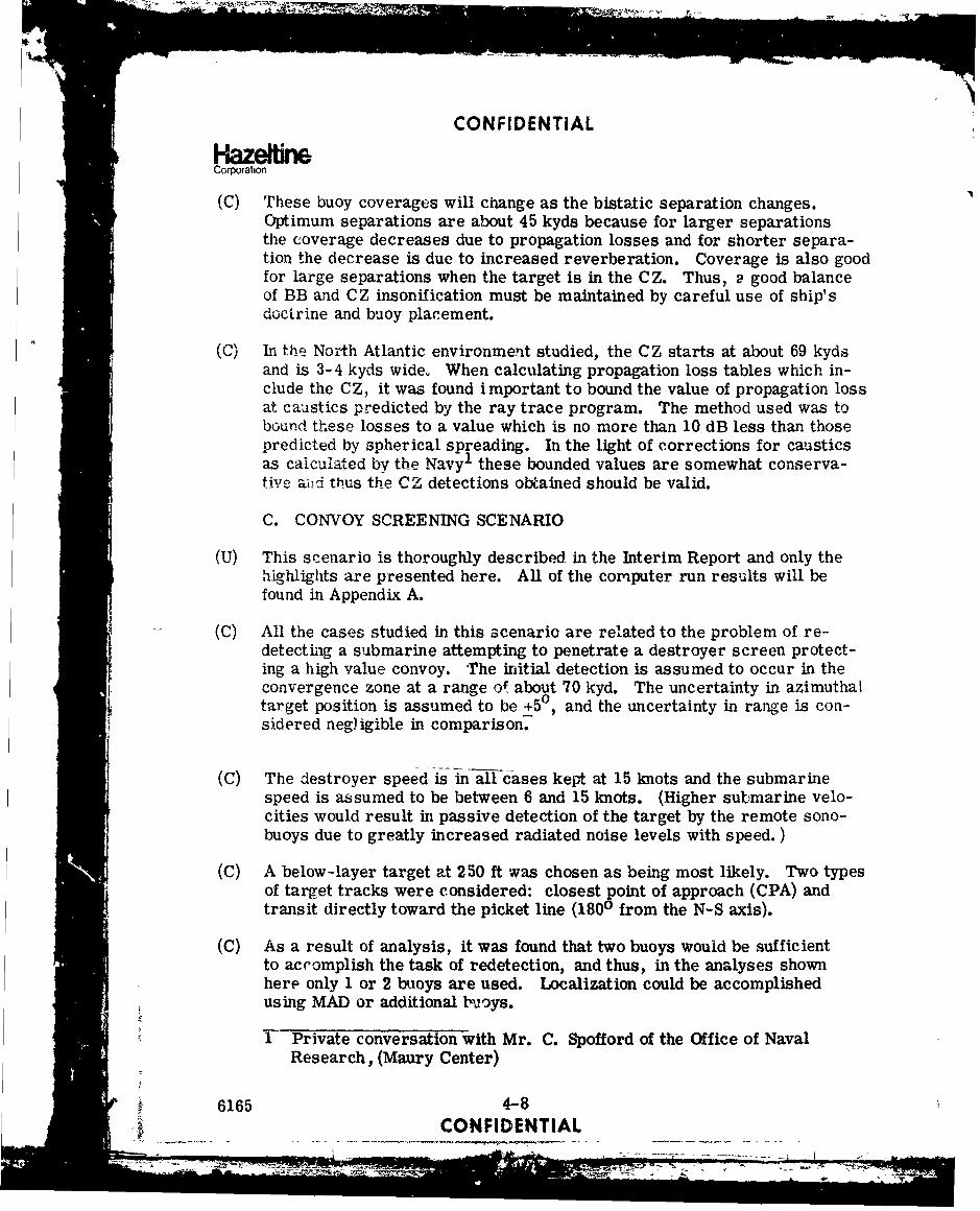
C. CONVOY SCREENING SCENARIO
(U) This scenario is thoroughly described in the Interim Report and only thehighlights are presented here. All of the computer run results will befound in Appendix A.
(C) All the cases studied in this scenario are related to the problem of re-detecting a submarine attempting to penetrate a destroyer screen protect-ing a high value convoy. The initial detection is assumed to occur in theconvergence zone at a range o! about 70 kyd. The uncertainty in azimuthaltarget position is assumed to be +50, and the uncertainty in range is con-sidered negligible in comparison.
(C) The destroyer speed is in all cases kept at 15 knots and the submarinespeed is assumed to be between 6 and 15 knots. (Higher submarine velo-cities would result in passive detection of the target by the remote sono-buoys due to greatly increased radiated noise levels with speed. )
(C) A below-layer target at 250 ft was chosen as being most likely. Two typesof target tracks were considered: closest point of approach (CPA) andtransit directly toward the picket line (1800 from the N-S axis).
(C) As a result of analysis, it was found that two buoys would be sufficientto accomplish the task of redetection, and thus, in the analyses shownhere only 1 or 2 buoys are used. Localization could be accomplishedusing MAD or additional buoys.
1 Private conversation with Mr. C. Spofford of the Office of NavalResearch, (Maury Center)
6165 4-8CONFIDENTIAL
LI II

CONFIDENTIAL
(U) Each exercise illustrated will be discussed by reference to a figure show-ing the physical geometry and another figure showing graphically the ef-fectiveness of each receiver used during that exercise. Using figures4-1 and 4-9 as examples, their contents and meaning are describedas follows:
(C) Figure 4-6 illustrates the geometry for a typical exercise showing thedestroyer track, five submarine tracks spanning the +50 in azimuthal un-certainty of the target datum, and the location of the remote sonobuoyswith their nominal coverage indicated as described above. The large cir-cles aroimd the submarine tracks indicate the extreme possible locationsof the target at the time the first sonobuoy is dropped. All exercises as-sume k. launch delay of 10 minutes and a helo speed of 120 knots, with anaverage time late of 22 minutes.
(C) Also located on this figure is a table containing the mission cumulativeprobability of detections (CPD) for the three ship tracks used. Theaverage is over the five submarine tracks run and the resulting valueis the CPD for detection by at least 1 of the receivers (based on an ex-pression of the form 1-(l-P 1 ) (1-P 2 ) (1-P ) for three receivers,averaged over the five submarine tracks. The worst case value refersto the lowest of the individual submarine track CPDs described above.These figures then give a good indication of the mission effectivenessand its weakest point.
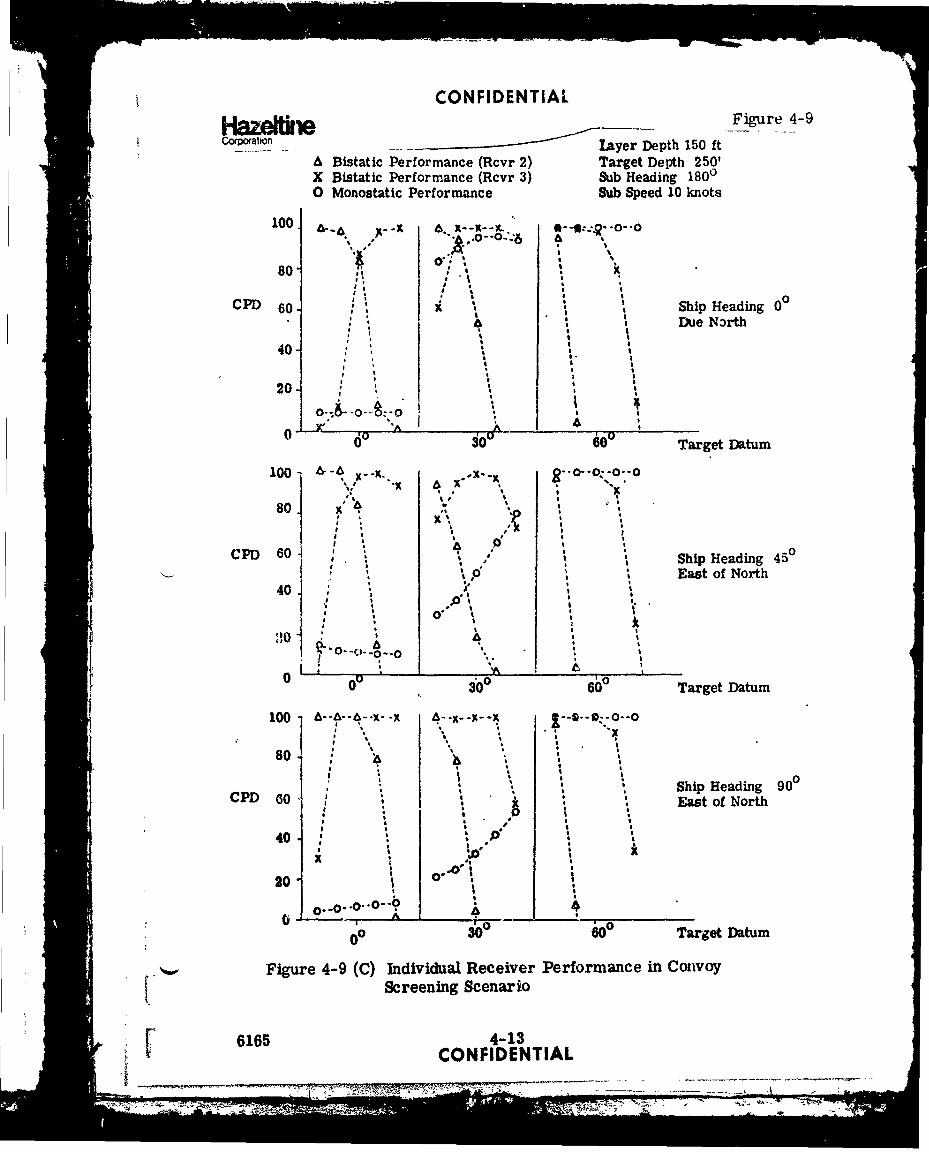
(C) Figure 4-9 illustrates the individual receiver dat,. presentation for atypical set of exercises. This data gives the CPD at the end of the exer-cise for each of the receivers used and thus allows a direct comparisonof the effectiveness of each receiver as well as a quick visual interpreta-"-;.on o4 the Wotal mission effectiveness. For example, in this figure, the
,.tat:! for iLe exercise involving a target datum at 600 and a. ship headingof 0V inafiates that the total mission effectiveness was good mainly dueto the rionostatic performance while the bistatic receivers were not use-ful for these target tracks. The data for a target datum at 00 and a shipheading of 900 indicates just the opposite; the mission effectiveness isgood due to the combined performance of the bistatic receivers while themonostatic performance is poor.
(C) Figures 4-6, 4-7, 4-8, and 4-9 show the results for a submarine in thetransit mode at a speed of 10 knots, sub track of 1800 and a depth of250 ft. For the target datum at 00 the results are all quite good, thebest being for a ship track of 90c. This is true because in general ifthe ship closes the target (as in the 00 and 450 ship tracks) the reverb-eration increases faster than the signal strength and so the E/B ratio
6165 4-9
CONFIDENTIALil-/ .............

CONFIDENTIAL
corpention Figure 4-6
kyds.704
Subine rinTrack j
•/ /1
S( I f
50
Sub Speed10 knots
Rem~ote Sonobuoys Course 1800\/Target Below
the layer
\bk 3 01 1 __
MISSION CPD
Ship 5 Track WorstTrack Average Case ,
0°0 .99 .98450 .98 .96
-2,0 900 1.00 1. O0
'+5
Rcvr I on Ship
ShipTracks
-20 -- 10 A -. ' 210 kyds
Figure 4-6 (C) Convoy Screening Scenario - Target Heading 1800Datum at 0°
6165 4-10
"C•NFIDENTIAL
.. - i i I-I I-

CONFIDENTIAL
HazebwnCorporation Figure 4-7
76J
kydF T Submarine //
Tracks
60-
Ni 1K cv 2c;50 \
I /
Remote Sub Speed
Sonobuoys 10 knots40 Course 180°
Target & lowthe Layer
30
MISSION CPDShip 5 TracKc Worst
0 • oTrack Average Ca se
20 / ' 0 00 1.00 1.00450 .98 .95I/ / " .900 .96 .80
t '/ /
10
/ Rcvr 1 on Ship
/ ShipTrack--o - --- 4 I I I
19 20 30 40 kyds 50
Figure 4-7 (C) Convoy Screening Scenario - Target Heading 1800,I Datum at 300
f 6165 4-11,} CONFIDENTIAL

CONFIDENTIALHazeltneCCorpation Figure 4-8
S,8
/ t.
Figure 4-8 (C) Convoy Screenin Scenariý, - Target Heading 180eDatum at 600
6165 4•S~CONFIDENTIAL
'~ 0
I vI I • ~ • •. i , ,,, • , •. i, , • , • i i i l 1 ! I I I I I
CONFIDENTIAL
Hazelie Figure 4-9co.Prat�iofl- - layer Depth 150 ft
* Bistatic Performance (Rcvr 2) Target Depth 250'X Bistatic Performance (Rcvr 3) Sub Heading 18000 Monostatic Performance Sub Speed 10 knots
1 X--X--X ,-m:- -O
80 , "
CPD 60. x • •Ship Heading 0040 *. Due N3rth
I S40- ,•,a I
0 0200 t
-A d ",^_,,,,_' ,_ _ _
00 0 .. 6 Target Datum
100) 6- 8-00z0-\0 -,- -X.. -x . x..X - o"°
80 Si Headn 45, , *3,,,3
a t
-- ao ' S. Pa! •, Ship Heading 450
40 East of North40 . ; • ,
. -o 0 0 B
0 it 6 Tage DatuI x _,-.o.. Io ',..
1 0 ..
40 A
2 ; 0 ;
0PD 60300 60 Target Datum
10 ~-'-4-~x A-00x-
1Scenn Scenari
616 4-13
oa I *t .O' '
_7I IS3
20 O*,CP hpeaig9
* Sreein Scnai
4016 4-13SONIDETA

I7'
CONFIDENTIAL
HazelUneCorporatior
decreases. This result appears true in all cases and thus unless thereare other reasons for doing so, it is not necessary or even wise for theship to close the target.
(C) With a target datum at 300 the best results occur for a ship course of 00.This is a demonstration of the effect of target aspect since this coursecauses the sub to present the best target aspect to the ship. The 900course is clearly the worst because it teivds to minimize the target as-pect.
(C) For a datum at 600, the mission CPD i,-; quite good for all ship tracks pri-marily due to the high rmonostatic performance due to the target aspect.Bistatic performance is poor and it can be seen from the figures that thisis due to a poor choice of locations for the buoys. The buoys in these andsome other sets of exercises shown in the Appendix were placed so as toattempt to protect the full quadrant; however, it will be shown belowthat this can be accomplished more effectively using a somewhat differ-ent criterion for buoy placement. For targets on a a CPA course, itwas found that the best results were obtained when the ship heading wasdetermined in relation to the target datum. One buoy was planted withthe sub and ship courses in mind. The data is shown in figures 4-10thruagh 4-13 and th,2 results are very good except for the case of theship heading straight at the target. Target datum beyond 250 are notanalyzed since it has been shown earlier that these cases are easilycove:-,ed due to improved target aspect in both the bistatic and monostaticmodes.
(C) Figure 4-11, the geometry for ship tracks making an anp%. of 450 w4;hrespect to the datum illustrates a very effective concept. In a submr rineCPA mode, if the ship's heading is chosen appropriately, the target anbe made to travel along a0path of minimum uncertainty. That is, the un-certainty of azimuth is +5 , but the tracks shown lie close to one anotherand thus the bistatic receiver is more efiectively utilized.
(C) It is interesting to see the effect of a variation of target speed on theeffectiveness of these same buoy plants for the ship heading of 450 rela-tive to the datu.n. The performance was considerably reduced when thetarget had a speed of 15 knots. This is due to the change in target CPAheading which c;uses some tracks to run "inside" the buoy, causing itto be either oatside the buoy coverage or in the area of specular interfer-ence.
6165 4-14,: CONFIDENTIAL
,' I

"CONFIDENTIAL
HazebneCorportin Figurr 4-10
kyd 50 7 - .-..
iS //
70-
Bistatic ¾Receiv rs/
40, Sub Course CPADepth 250'
I Buoy Plant Assumes~ /Sub Speed of 10 knots
0/Target Belo v
the Layer30",
.I -arg'er 5 irack CsDdm Average Worst Caset 50 .95 .79
0 .90 .7320. 25 .90 .58
, /10- Monostatlc Rcvr on Ship
ShipTracks
0 to •0o 30- 40 kyds
Figure 4-10 (C) Convoy Screening Scenario - Target Course CPA;Ship Course 00
6165 4-15CONFIDENTIAL
_ ,-•"' o i l

CONFIDENTIAL
Hazetrdne Fiwe 4-11Corp•o• .ton
-' .\- rarget
sky i 0 Datum
.f .•- - -- O ----N. -: / s•0070•,• t 0 -• ,s
I <. •5
60
B staticeceivers
50..
Sub Course CPADepth 250'
Buoy Plant Assumes40 •Sub Speed of 10 Knots
Target Belowthe Layer
MISSION CPD
2 0Datum Average CWse
/ 25 1.00 1.00
10 .
ShipTracks Monostatic Rcvr on Ship
10 20 30 40 kyds
Figure 4-11 (C) Convoy Screening Scenario - Target Course CPA;Ship Course 450
6165 4-16CONFIDENTVALi I ! ................. ........."-S

CON FIDEN'J lALCorpor7an
Figu.-e 4-12Cu"p. on
kyds •/ Target .kd 50 Da um "
50
80-0\' / - ,' -
Bistadic50- Receivers
4'ub Course CPA
/ Depth 250'
40 !Buoy Plant AssumesIo %b Speed Af 10 Knots
I. ~ / /Target Belowthe layer
30
SMISSION CPD
I a-rget 5 Track Worst20 // Datum Averae Case
so° 1.00 1.O00
1,6° i. 00 ). o0S250 1.00 1.00
I cMono-static Receirer on Shipi Ship
STracks!, '0 10 o o. 30 40 ld~s
Fig-aLre 4-12 (C) Convoy Screening Scenario - Target Course CPA;•i Ship Course 90o76165 4- I
--- • •CONFIDENTIAL
i. •" - -;-• :==-:=-_...__'t " .•"UC•-I--

CONFIDENTIAL
P"aze re Figure 4-13Corporaticn
1aye: D)epth 150'X Bistatic Performance Target at 250'0 Monostatic Performance Submarine Tactic CPA
Submarine Speed "10 knot.-
100 X . X-I S
1 , 4• •t K'
I ,'x %''80- / x
xKC o-D ,0 ',o
CPD 60 . • Ship Heading 00with Respect to
40 " Target Datum
20
I I
0 150 '5' Target Datum
100
801
CPD 60 Ship Heading 450with, Respect to
40 Target Datum
20
25ý Target Datum
100 X---x--x--X % -- x--X-K--K --X--X--X--Ax0 ,., 0.ý
80 1"-.
CPJ) 60 Ship Heading 900
with Respect to
40 Target Datum
204
-0 .- 1 5 u- it Target Datum
Figure 4-13 (C) 1ndiVidual Receiver Performance in Convoy Screening
Scenario
6165 COtidt4iNTIAL* - - - - 1,- ----- I --- "------

CONFIDENTIAL
C.xoatton
(C) A new buoy plant was tried to cover variations in target speed- nearunity effectiveness was obtained for target velocities of 6, 10 and 15knots. Thus, a signle buoy plant is extremely effective m detecting atarget in the CPA mode regardless of the initial target datum.
(C) Earlier results have shown that two properly placed buoys can providehigh effectiveness against a target traveling in a straight line toward thepicket ship.
(C) In summary, for convoy screening, three buoys should be sufficient toprevent the penetration of a destroyer screen by any target once it hasbeen detected in the convergence zone.
(C) An optimum strategy to accomplish the above is for the ship to follow acourse which makes an angle of about 450 -4,.t1 respect to the target datumand to plant three sonobuoys, one which assuunes a target track of CPA andtwo which assume a target track of 1800.
(C) For a submarine which chooses 0 follow a course other than CPA or 1800and which intends to attack the convc', further down range, an advancingscreen can be used as illustrated in figure 4-14. This strategy forces thetarget to penetrate the buoy barrier in order to present a threat.
D. TARGET PROSECUTION SCENARIO
(C) Two scenarios are discussed here, one assumes an initial active CZ con-tact against a conventional submarine with an azimuthal undertainty of+50. The second assumes a SOSUS detection against an SLBN target.Many computer runs were made to determine optimum buoy configurationand ship tactics and on!; the highlights will be presented in this section.A full summary of computer runs is contained in Appendix A.
(C) The goal of this analysis is to redetect a target which may attempt toevade the ship. This is accomplished for each scenario by calculatingthe cumulative probability of detection for each submarine track as thesubmarine runs in a different straight line track from the datum. Foreach target datum, 12 sub tracks are run with courses from 00 to 3300in steps of 300. In order to verify that this was a fine enough sampling,one scenario was analyzed with 150 target track increments with littlechange in total mission effectiveness.
6165 4-19CONFIDENTIAL
~ ~ ~ -+s- ~4 AM-

CONFIDENTIAL
HazeffieCorooration Figure 4-14
4,41\ 65'SA TIC RiECE/VEfi
TARCE61--
DAU 0 ADWVANCING BARR/ER
00
TARLOET CONTACTLOST,
(TRAN55MITTER
Figure 4-14 (C) Advancing Bart ier for Convoy Screening
6165 -4?21-- ____CONFIDENTIAL
77~* <*a i
CONFIDENTIAL
Hazetirne
(C)1 Buoy p!gnts wpre determined from 10° target datum uncertainty plustile late consic rations. Runs were made for target datfum •nanning10 ' uncertainty. There was little performance variation with actualtarget position across this uncertainty. Therefore, for subsequentanalysis only one cdaum was -.co...idered.
(C) Each figure is self-contained in that the scenario and results are all con-taLned on the illustration. The data in the upper right gives the scenario,system data and initial conditions. The sketch in the upper left showsthe ship's track, the target datum and the buoys numbered in the orderin which .,ey are dropped by the helico'pter. This is followed by one ormore sE. :s of radial lines which represent the various target tracks fol-lowed by the submarine from the indicated datum. The numbers locatedon the center of these lines represent the total mission effectivenessagainst a target following that track. (For an explanation of total missioneffectiveness, see Section IV-C.) The numbers at the end of each linerep-esent the cumulative probability of detection for each useful receiverfor that track apd the receiver number. (Thus, . 95-6 means receiver 6had a CPD of .95 for that target track.) The number M is the average ofthe total mission effectiveness over all the tracks and is thus most indica-tive of the success of the strategy used. P M is the average multi-static effectiveness over all the tracks usirig nýI the highe'st individualCPD for each track. P is the same as PMULT using only the high-
est bistatic receiver CrJ"P. OO is as above using only the mono-static system performance. and P . thus give a relativeweight to the importance playe'P~y the morioYaM receiver and thebistatic receiver in obtaining the total mission effectiveness. It will beobserved in the following two sections that the SQS-26 monostatic systemplays an important role in mission effectiveness when the target electseither to run toward the ship at an angle which results in a good targetaspect or when the target moves away from the ship in such a manner asto keep it in the ship's CZ for some reasonable period of time. An intelli-gent target would probably avoid these courses but then the bistatic buoyswill come into play more often.
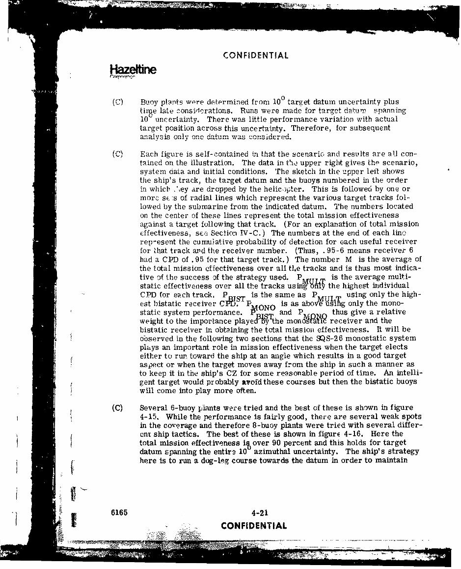
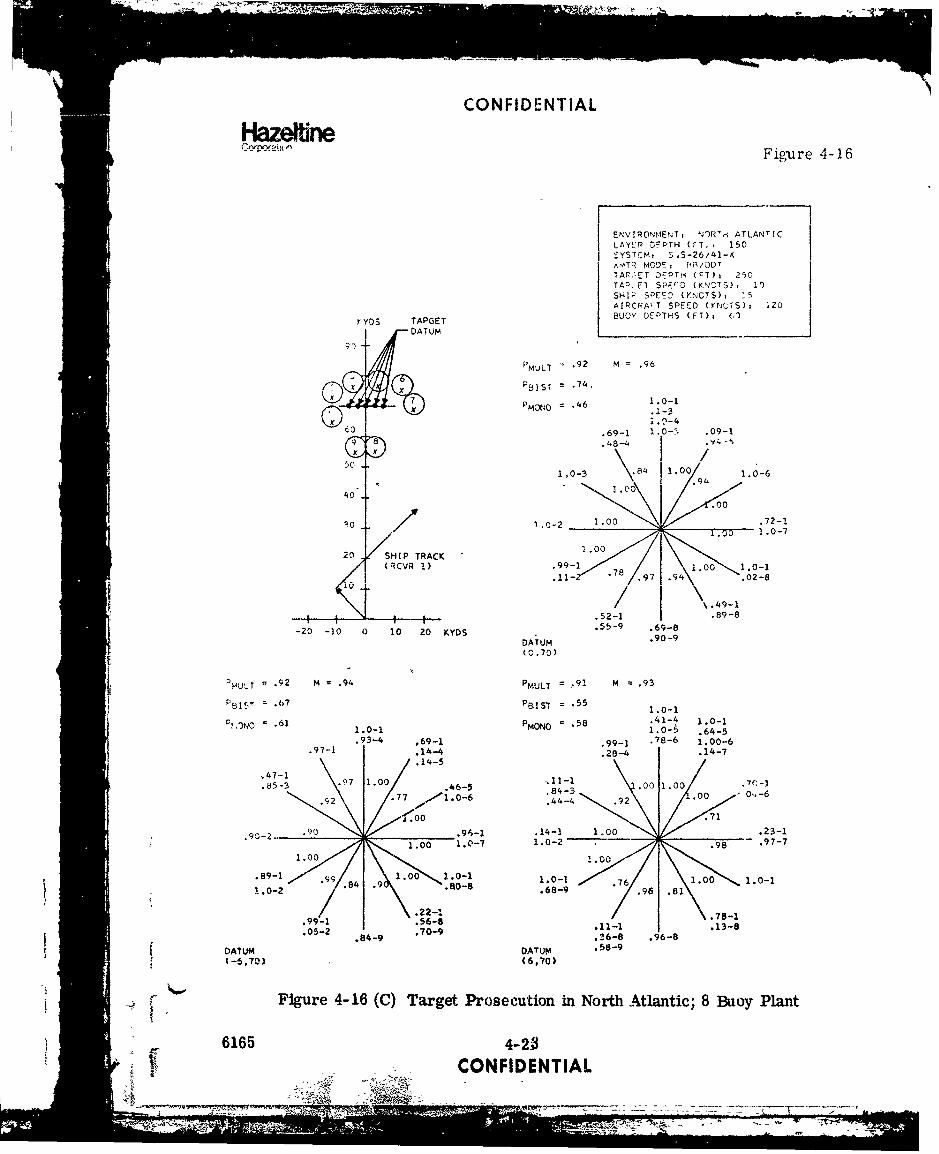
(C) Several 6-buoy plants were tried and the best of these is shown in figure4-15. While the performance is fairly good, there are several weak spotsin the coverage and therefore 8-buoy plants were tried with several differ-ent ship tactics. The best of these is shown in figurE 4-16. Here thetotal mission effectiveness iA over 90 percent and this holds for targetdatum spanning the entire 10 azimuthal uncertainty. The ship's strategyhere is to run a dog-leg course towards the datum in order to maintain
|I
"6165 4-21
CONFIDENTIAL
LL -I

rimlrlr•kic LmklT I Al
Corporation W Figure 4-15
F P/ MREN T , NORTr ATLANTIC!ýAIER ý,IE TI (r'): 0,,,~~rT" (. 5
SYSTEM, SQS-2t,/41-XXMTR mODE: t elODTTAR-ET D'T,, (FT) 3 250
TARGET SPEED (KNOTS)% 10
SHIP SPEED (KNOTS): 15
AIRCRAFT SPEED (KNOTS)s 120
KYDS BUOY DEPTHS (FT)i 60
9 0 -. T A R G E Tm = .8
~TARGEDATUM PMULT = .80 M = .83
Q PSIST = *69
.PMNO = .46
r4 ,95-6 .09-101 O .69-1 .12-5
1.00 .1940o - .70 _.00 .9 9
.96301.020 1.,P TRACK< RCVR 1) .99-1 7 98-
.74- .8
20
5 2 - 1 - -3-4-- -. 44-3 .47-3 .86-3
-20 -10 0 10 20 KYDS DATUM(0,70)
PMULT = .78 M = .81 PMULT = .78 M =.78
P =ý15T = .53 PBIST = .60
PMONo = .61 PMONO .58 1.0-1.82-5
.6- 99..1 1.0-6 1.0-1.- 1.0- .69-1 .68-6 1.0-5
.30-77.6--
.47-1 .98 .0 1.0-5 .- 1.00 .70-1
• .98 .00 .o1-1I/ °/..887 1.0-7 1.00
.48 .71.
.00 .14-1 .98 .23-1_________.96-1 -______ .08-4
1.00 .98-4 .98-2 .29
1.00 1.00
.80- .97.0 1.0-4i.o-2 .0 .64 " 1.0-3.
.22-11.99- .54-3 1 .76-1.20-k .01-1 .08-3
DATUM DATUM(-6,70) (6,70)
Figure 4-15 (C) Target Prosecution in North Atlantic; 6 Buoy Plant
6165 4-22CONFIDENTIAL
CONFIDENTIAL
Hazelfire Figure 4-16
ENV IRONMENTT N)R'.i ATLANTIC
LAYEP IOEPTH (T., * 150SYSTEM, S .S-26/,4I-,(
xTR MOD'-> R P/ODTTAPC T DEPTH (FT), 27,0TAZ, SPE'D (ENCTS), 10SHI' SPEED (KNCTS), 1_5
AIRCPArT SPEED (VNUTS): 120
y YDS TAPGET BUOY DEPTHS (FT)i D63
PMULT = .92 M = .96
%PSIST .74,
PMoNo = .46 1.0-1
(f .69-1 1.0-5 .09-1
50
1.0-3 84 1.0 1.0-6
40 1.00
A - ~ .000
30 1 .0-2 1.00 .. 72-1
20 SHIP TRACK 1.00
(RCVR 1) '99-1 1.00 1.0-1-1- / .97 4\ .02-8
\ .49-1
.52-1 .89-8
-20 -30 0 10 20 KYDS . .69-8
DATUM .90-9(0.70)
PMULt = .92 M H .94 PMULT = .91 M = .93
PBIS.• = .6>7 PeLIS'T = .55 1.0-1
PI 'NO .6 PMOO =-58.41-4 1.0-1, ,61 1.0-1 PMON = .58 1.0-5 .64-5
.93-4 .69-1 .99-1 .78-6 1.00-6
.97-1 .14-4 .28-4 .14-7
.14-5
47..1~ 1.-000 1 0
.85-3 .1.0 46-5 .8 -.3
9.92
.7 .0-6 .44-4 .
.00
.90-2.. _______.9-1 .1-1 1.00 .71 .23-1\ 1.00 1.0-7 1.0-2 .98 97-7
1.00 1.00.89-1 1.00 1.0-1 1.0-I .761.00 1.0-1
.84 .9 .80-8 .68-9 .96 .81
.22-1 .78-1.99-1 .68.78-99..56-8 .11-1 . 13-8.05-2 .70-9
.84-9 .26-8 .96-8
DAIUM DArUM .58-9
S(-6,70) (6,70)
Figure 4-16 (C) Target Prosecution in North Atlantic; 8 Buoy Plant
6165 4-20- - •CONFIDENTIAL
I4 - -IVIk iý

CONFIDENTIAL
HazeftineCorpalion
CZ coverage for targets running away from the ship while not closingtoo rapidly on targets headed towards the ship. The buoys are plantedon a spiral determined by the time late of the 120 knot helicopter ateach location. Gaps in buoy coverage are left where monostatic detec-tion is virtually assured due to a closing target with good aspect. Thisparticular plant waq analyzed in detail and the remainder of the runs areshown in Appendix A.
(C) An important result found here is that in about 50 percent of the casesthe target is detected simultaneously by two or more receivers and thuslocalization is possible. Such a localization could be followed up eitherby a weapons drop or by a MAD sweep followed by a weapons drop.
(C) In order to investigate the effects of time late, several scenarios wererun assuming rocket launched sonobuoys where the delivery speed wasabout 1400 knots. This significantly reduces the time late spiral and thusreduces the number of buoys required for detection.
(C) In this case, it was found that 3 buoys were sufficient to give performanceequal to that of 8 helo-dropped buoys. This run is shown in figure 4-17where it was found best to run the ship straight at the datum at a reducedspeed of 6 knots, which maximizes the time the target remains in the CZ.
(C) Because of the much smaller uncertainty area when using rocket launchedLonobuoys, it is possible to operate the SQS-26 in t.. BB/TRACK modewhere it has a source level of 142 dB and reduced reverberation interfer-ence. This will result in increased buoy coverage and now two buoyswill give the coverage of the 3 used previously.
(C) In this BB/TRACK mode of the SQS-26 (AX) or (CX) the monostatic per-formance is considerably increased. However, the bistatic receiversare still required in order to hold the target for localization.
(C) Target prosecution studies were also carried out against an SLBN typesubmarine. The SLBN is considerably larger than a conventional sub-marine and is assumed to average 5 dB more target strength. CZcontact prosecution of such a target was considered trivial, based on re-sults for a conventional submarine. Instead, a brief study was madeto determine the uncertainty area which could be covered by 8 buoysagainst an SLBN.
6135 4-24CONFIDENTIAL
1ý1-

.- -.- .
CONFIDENTIAL
HbzeftneCoW•ton Figure 4-17
ENVIPONMENT, NOPTH ATL.'ICLAYCR DEPTH (rT)i 150SYSTEM, $US-2( /41--,.XMTR MODE, SB/ODTTARGF.' DEPTH (FT), 2!0TARGET G'EýD (KNOTS), 10SHIP SPEED (KNCTS)i 15AIRCRAFT SPLc.D (KNOTS)i 1400BUCY DEPTHS (FT), 60
KYDS
90 TARGET
80DATUM PMULT = .97 M = .98
PBIST = .83
PMONO = .80
60 ,- .96-1 1.0-1.07-2 .06-4
50 10 1.C .96 1.0-1.31-3 .31-3
40 .99-2 1.010,,.. 98-4
1.00.0 .05-1 .0511.0-2 1.00 - 1.0-4
1.0020 1,0-1 1.0-1
.84-3 1.00 .oo0 .82-3
10 SHIP TRACK .99-4 -- 0 .97-4(RCVR 1)
-4---I-- 1 - 0-1 I 1.0-1-20 -10 0 10 20 KYDS DATUM 1.0-3 .44-1 1.0-3
(0,70) .65-3
PMULT = -92 M =.95
PBIST = .64
PMONO .86
.56-1 .90-1.99-1 .09-4
1.0-.99 .56 1.0-174-3• .91 .24-3: 29-4 1.00• 1.0-3
;.0.00i.49-10- .00 .79-1
.85-3
1.0-1 1.0-11.0-3 41'l+0/ .87 . 1.0-4
S.41-3 .50"-1 .47-4
DATUM .95-4 .73-A(6,70)
i ' Figure 4-17 (C) Target Prosecution in North Atlantic; 3 Rocket-LaunchedBuoys
6165 4-24. .CONFIDENTIAL

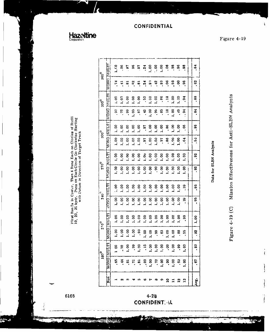
CONFIDENTIALHazeffneCorporation
(C) The buoy plant is shown in figure 4-18 along with zome of the target tracksrun. The ship is assumed to be about 90 kyd from the center of the uncer-tainty area and thus its tactic is to first make a high speed sprint towardsthe daturm and then slow down to a speed of 15 knots. This avoids thepossibility of the sub running outside the range of the SQS-26 trans-mitter.
(C) Thirteen target tracks were run for each target direction; one at the cen--ter of the uncertainty area, and four each on circles of radii 10, 20, and30 kyds.
(C) The results for these runs are shown in figure 4-19. With the exceptionof a few weak spots, the effectiveness of the multistatic system againstthis type of target is quite good. These results could probably be improvedeven more if the buoy plant were slightly modified.
(C) Thus, it appears that a multistatic system comprised of the SQS-26 and 8remote sonobuo~s can be effective against an SLBN in an uncertainty areaof about 700 nm (a radius of 15 nm). This area could be increased evenmore by utilizing two ships and increasing the spacing of the buoys.
(C) For purposes of comparison, an analysis of the CASS system was madein the same scenario as that of the SQS-26/41-X system shown in figure4-16. The performance of the system against a 300' target is -lMustratedin figure 4-20. Additional target depths of 55' and 600' were analyzed;these results appear in the appendix.
(C) The operations analysis model cannot presently be used to analyze CWsystems and therefore the CASS system was analyzed in the FM modeeven for high (10 knot) doppler targets. Use of an acoustic programdeveloped to analyze CW systems shows that the range coverage of theCASS buoy in the CW mode is almost identical to the coverage in the FMmode as shown in figure 4-5. The variation of coverage with target as-pect in the FM system does not correspond to variations of coveragedue to target doppler. The difference is that the CW system would con-tact the target somewhat sooner (as the target was approaching the buoy).then lose it temporarily (target at beam aspect) and then again contactthe target as it started moving away from the buoy. The net area cover-age however predicts almost identical system performance. Thus, theanalysis of the CASS system can be accomplished using FM predictions.
• 6165 4-266165 CONFIDENTIAL
WIN-

CONFIDENTIAL
HametnCpaii•n UneFigure l-18
Environment: North AtlanticLayer Depth (ft): 150
so--yIb System: S'S-26/41-xXmtr Mode:' BB/ODTTarget Depth (it): 250Target Speed (knots): 10
8l Ship Speed (knots): 30; 15
a' Aircraft Speed (knots):, 120
Bistatic Receivers
40"
240 40 too KVYD-0 4
I
-60--40- .30 Ktfr0"3
TRACY"
Figure 4-18 (C) Scenario for Anti-SLBN Analysis in North Atlantic
• •6165 .4:• ....
CONFIDENTIAL
= =- __-- -
, i i I i i I
CONFIDENTIAL
Hazktkj~r*
Copatc Figure 4-19
' 0 r-1r0 00> 0 tz w
ol -4 w4 (.4 m to .o o (0 00 oV- r o (0c cq 03 'r0 0 000 m 0
a m~ 0 c ,0 0 too0 0O (0*o
00 c: -: - -ý o4 W~- -4 o
m~ 00 t- C71 0 uhUM w~ 0 0 .
C .z -4.
Q 000 o 0 (0 -41 .4 -
0 -
0 0j 0 0j
-4 -4 -4 -4- 4 444(
0 ;0
0 0 0 0 0 0 , 0 0C , 0 0 c.4
c) 2 0 0000 oe oo o C) 0o l
C) a 0000m m-4
C9
;L -4_ _ _ _ 1; .Z. 0 00000000000 0 co-4
00
M 0 LM~ 0 0 0 0 0 0 0o
-4 U' 4 4I
C. M (.w 0 0 0
0- m m
6165 4-2t8
CONFIDENT: \L

CONFIDENTIAL
Corporaltion Figure 4-20
ENVIRONMENT, NOqTH ATLANTICLAYER DEPT's (FT)1 150SYSTCM, I1QS-26/CASS
ITR M.ODEU I 3B/ODT, OP"ISET VCPTH (-T), 300
TARGET SPKED (KNOTS), 10SHIP SPEED (KNOTS), 15SA:RCRAFT SPEED (KNOTS), 12J
KYM) BUOY DEPTHS (FT), 1500
90
SPMULT = 1.00 M = 1.00TARGET
DATUM PCASS =1.00
1 - .46 1.0-1.6646 1.0-1
60 .20-2 1.0-4 .07-1
40 1 .0 .0-0 1 .00 -
S1.0-2 X100~ 1 ."00/ .70-1
30+ .82-3 1.00 1.0-5
20 SHIP TRACK .97-1 1.00(VR, v1) - 1.00 100 .1.0-1
10.5-6 1 . 0-
S• | • - ' I.48-1 .4.6-1.
00DATUM 1.0-2 .97-6 1.0-5-20 -10 0 10 20 KYDS (0,45) 1.0-6 1.0-6
4 ( Figure 4-20 (C) CASS System for Target Prosecution in North Atlantic
"6165 4-29CONFIDENTIAL
-- ___r-

CONFIDENTIAL
HazeltineCorporahon
(C) In the North Atlantic, it is found that the SQS-26/41-X system operatesbest with the receivers at 60' because the deep (1500') bistatic receivershave more reverberation. Reverberation is not a major problem forthe CASS system; the deep system pcrfcrms better against below layertargets than the shallow (60?) CASS system because of improved propa-gation conditions.
(C) Five CASS buoys were deployed around the same time late spiral as thatused for the bistatic case. The system effectiveness is shown in figure4-20. Comparing these results with those of figure 4-16, it is clearthat equivalent performance could probably be achieved with only 4CASS buoys.
(C) The CASS system was also analyzed for targets at 55' and 600?. For thedeeper target, there is little difference in system performance. For atarget at 55?, however, the CASS system at 1500' performs somewhatpoorly due to the target being in the layer and the non-reciprococityof shadow zore propagation to a directional buoy with a depression angleof 0 . In contrast, the bistatic system with a shallow receiver will per-form weli against an in-layer target. This situation could, of course,be remedied by deploying CASS at 60' but then the performance for be-low layer targets would suffer.
(C) To compare the bistatic receivers with CASS is not straightforward.CASS alerts the target to the fact that the localization process has be-gun. In addition, detection of high speed targets (greater than 15 'knots)would require the delivery of passive buoys (e. g., SSQ-41). Differenttarget depths also affect the comparison as shown above.
(C) %gnoring these differences, we may compare the systems on the basisof four CASS buoys to eight 41-X buoys.
(C) The cost of a CASS buoy is around $800 while that of the 41-X is about
$ 100. Thus, the bistatic system has a cost effectiveness advantage offour-to-one over CASS. From a tactical point of view, the bistaticsystem is superior in that a target hearing an active source pingingat close range will alter its course to present a reduced aspect tothat buoy thus reducing buoy performance, while in the bistatic systemthe trans-Uitter is at a large distance and the target has no way of lkow-ing whether it has been detected. If the ship cannot get within CZ dis-tance of the target in time, then CASS would be the better system fortarget prosecution because it is a self-contained system needing onlyan aircraft to deliver it. Except for this case, however, it appearsthat the bistatic system is superior to CASS for target prosecution.
6165 4-30CONFIDENTIAL

UNCLASSIFIEDCowtion
SECTrION V (C)
MEDITERRANEAN OPERATIONS ANALYSIS
r
A. ENVIRONMENT DESCRIPTION
(U) Two Mediterranean environments were studied; one where a i00' layer
was present typical of the mciths from October to March, and another
where no layer was present which is usual for the months from April
to September. The parameters describing the environments studied
are shown below:
WINTER
Water Depth (1t) 12000.0
DSL Depth (ft) 150.0 1000 (day)
Layer Depth (ft) 100. 0
Bottom Scat. Coef. (dB) -28.0
DSL Scat. Coef. (dB) -50. 0 -60. U (day)
Wind Speed (knots) 13.0
Sea State 3.0
MGS Bottom Class 3
6165 5-1
UNCLASSIFIED
miic -.-----.-.- =7--
HUNCLASSIFIEDCorcation
VELOCITY PROFILE
Depth (ft) Velocity Gradient 0oo0 5050 510 51o50
(ft./sec) (ft/sec/ft) (if/bec)
0.0 5024.6.0250 2000
100.0 5027. 1-. 8140
150. 0 4986.4 -14 .-. 1340
200.0 4979.7
350.0 4967 -.0200 6o
.1967 1(!t)380.0 4982. 6
.0075 0oo500.0 4983.5
-. 0140700.0 4980.7 -10oo
.016812000.0 5170. 3
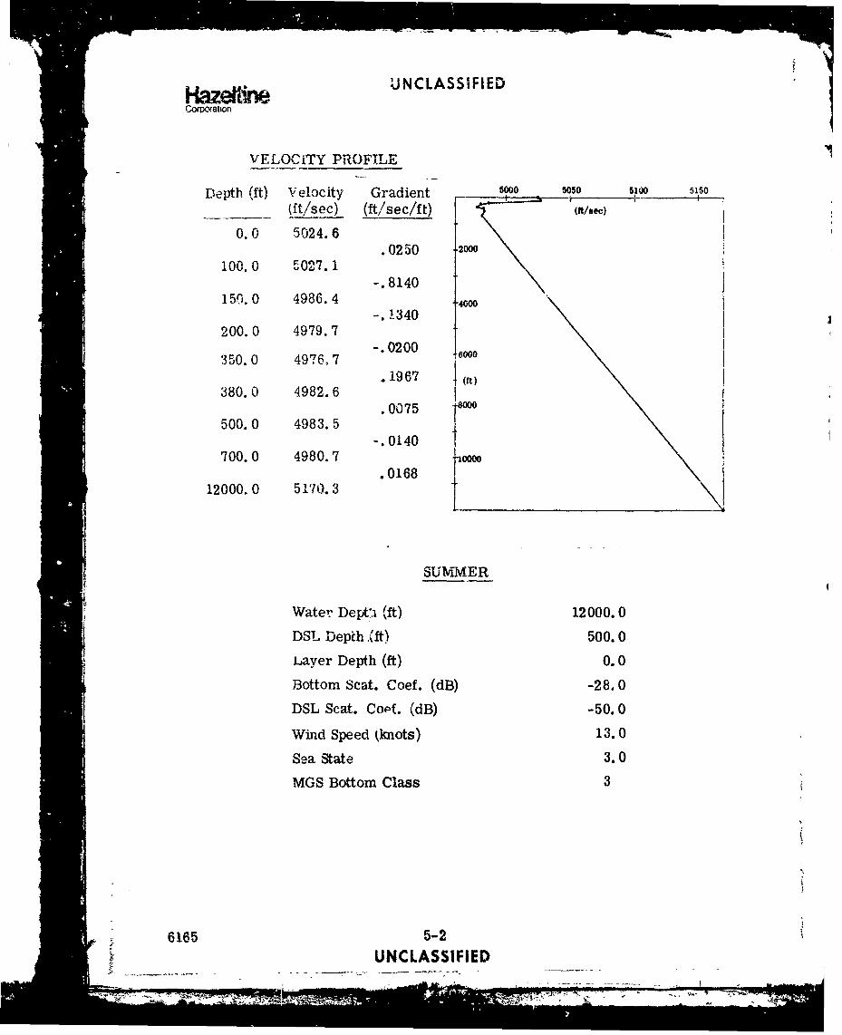
SUMMER
Water Dept'.i (ft) 12000.0
DSL Depth (ft) 500.0
Layer Depth (ft) 0.0
Bottom Scat. Coef. (dB) -28,0
DSL Scat. Conf. (dB) -50.0
Wind Speed (knots) 13.0
Sea State 3.0
MGS Bottom Class 3
6165 5-2UNCLASSIFIED
i I I I I I

CONFIDENTIALHazelfne
VELOCITY PROFILE
Depth (ft) Velocity Gradient(ft/sec) (ft/sec/ft) 0o . 0o _!
-. 01260. 0 5024. 1 2000 (tse
80.0 5023.1-. 0467
140.0 5020.3 - 7
000-. 6767 T¶o0200. 0 4979.7 -. 0450500.0 4966.2
.0118 (f
i000. n A497. 1.0136 -0
3000. 0 4999.3. 0165
6000. 0 5048.7 "10000* 0170
12000.0 5150.5 1
B. ACOUSTIC PERFORMANCE
(C) The coverage of a bistatic receiver at a depth of 60' and separatedfrom the SQS-26 transmitter by 25 kyds in an environment with alayer is shown in figure 5-1. The very broad coverage is a good in-dicator that the system will per form very well in this environment. Theodd shape of the contour is due to the start of the CZ at a range of 32 kydsfrom the transmitter. As the bistatic separation increases to 45 kyds,the coverage becomes more circular with the width reduced by about 30percent. For deep receivers (1500') the coverage for below layer targetsis better than for .- ,allow receivers; however, for in-layer targets thecoverage area is only about 6 kyds in diameter..
(C) For a velocity profile with no layer, the coverage for a 60' buoy is shownin figure 5-2. This poor coverage is due to the fact that there is a shadowzone caused by the receiver being near the surface but there is no surfaceduct to propagate energy for scattering into thi3 shadow zone.
I
F 6165 5-3
CONFIDENTkAL
JJ . . N

CONFIDENTIAL
Hazeb*nCo0poration Figure 5-1
MediterraneanDepression Angle 50BB/ODT100' layer Depth
o 55'/300' Target Depths1200 Sector Insonification
Target Strength 15 dB- Receiver Depth 60'
/ ID
. W
/
0 W
" 6165 5-4V CoCONFIDENTIAL o
II i ~-] I II I1 -- I• i1l

CONFIDENTIAL
Corpoatio Figure 5-2
Mediterranean 0- Depression Angle 5
BB/ODTNo Layer5,51/3001 Target Depths1200 Sector LrisonificationTarget Strength 15 dBReceiver Depth 60'
8
6
12 *6 4 2 2' 4' 6 8 10 kyd
.- 4 Bistatic Receiver
-10
.- 45
`XMTR
Figure 5-2 (C) Coverage of 41-X Sonobuoy; Mediterranean withNo Sirface Duct; Receiver at 60'
6165 5-5CONFIDENTIAL
`7 ___-N

CONFIDENTIAL
Cof ation
(C) For a deep receiver i hi . 4h, - is niuch im-proved as shown in figure 5-3.
(C) Another interesting fact about these environments is that a receiver at1500' is in a depressed sound channel and therefore propagation lossesfrom a target to the receiver are quite low over very long ranges so per-
formance is limited in this case mainly by the losses in th,, transmitter/target path.
(C) Because the critical depths in the Mediterranean environments are onlyabout half that of the North Atlantic, the CZ appears at about half therange of that in the Atlantic. The CZ's begin at about 32 and 36 knots re-spectively for profiles with and without a layer and reach out to about57 kyds. This very broad CZ allows virtually all detections to be madein the CZ area and the resulting system performance can be expected tobe quite good. Because of the appearance of the first CZ at 32 kyds, itwas considered feasible to investigate the possibility of target contact andprosecution in the second C Z which staits at 64 kyds and extends out be-yond 80 kyds. As will be seen below, thi.s performance turns out to befairly good.
(C) It is interesting to compare the performance of the multistatic systemwhen the SQS-26 is replaced by the SQS-23. Figure 5-4 shows the rela-tive monostatic performance of the 26 and 23 in the Mediterranean. Itis clear from the figures that the monostatic performance of the 26 willbe very good resulting in near unity cumulative detection probabilitiesfor targets which pass through the zone. SQS-23 coverage is considerablysmaller and this performance will be correspondingly lower.
(C) Figure 5-5 shows the coverage of a bistatic receiver using the SQS-23as transmitter. Comparing this with figure 5-1, the performance usingthe SQS-26, gives a good indication of the decreased performance to beexpected in exercises using the SQS-23/41-X multistatic system.
C. SCREENJNG SCENARIO IN THE MEDITERRANEAN
(C) Very little need be said about the effectiveness of convoy screening inthis environment. If a comparison is made of the buoy coverages in theNorth Atlantic and Mediterranean and it is recalled that convoy screen-ing is very successful in the North Atlantic, then it must be concludedthat screening operations in the Mediterranean will be highly successful
1•. and the same doctrine could be used here. )
6165 5-6Vi •CONFIDENTIAL

CONFIDENTIAL
Cocpcratum Figure 5-3
MediterraneanDepression Angle 50BB/ODTNo Layer55'/300' Target Depths120' Section Insonification
k:Fds Taxget Strength 15 dBReceiver Depth 1500'
.1'
E/B = 10 dB 6 Tgt 300'
/B 1o dB . Tgt 55'
1 ý 0 4 2 1 2
10 cy d s
Bistatic
01eceiver
I XMTR
Figure 5-3 (C) Coverage of 41-X Sonobuoy; Mediterranean with noSurface Duct; Receiver at 1500'
6165 5-7
CONFIDENTIAL
"•'''•v''' '' w'Y•v'I J£ :"• - -7 •:--- " -7... ...... - • ,
'.. . . n --

CONFIDENTIAL
HazeffireCorporation Figure 5-4
MediterraneanDepression Angle 50BB/ODT100' •ayer300' Target Depth
@• '.'20
60 40 20 0 20 40 60
S.S-23
"40
S.2I
60 40 20 0 20 40 60
E/B > 10 dB in Shaded Areas
Figuie 5-4 (C) Comparison of SQS-26 and SQS-23 Monostatic Coverage
6165 5-8CONFIDENTIAL
- .-...-- !!-!-ISI I [
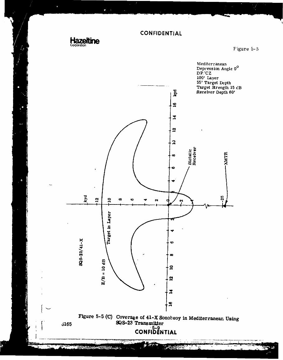
CONFIDENTIAL
Figure 5-5HC-rawen e
MediterraneanDepression Angle 00DP,/CZ100' Layer55' Target DepthTarget Strength 15 cIBReceiver Depth 60'
co
.4
.,4,I..
.>% C4 -qC /oChIA-4•
C.,Q
.41
Fig-are 5-5 (C) Coverage of 41-X Sonoruoy in Mediterranean Using,165 SQ.S-23 Transmitter.5-9
"CONFIDENTIALI , ,, • : '• • " T " 1 '",• --'.
, - -. .- , . • • •

CONFIDENTIAL
HazeltineCorpoation
D. TARGET PROSECUTION IN THE MEDITERRANEAN
(C) This scenario assumes a target datum near the middle of the CZ,(40 k-ds with layer, 45 kyds without layer). An azimuthal uncertaintyof +5 is assumed and buoys are deployed on a time late spiral determiner'by the track of a 120 knot helicopter.
(C) Figure 5-6 shows the best of a series of 6 buoy plants for a target at 300'using 1500' CC1Vi;5. As can be seen the mission effectiveness is veryhigh and because of the overlap of buoy coverages, the probability ofsimultaneous detection and thus of localization is quite high.
(b) A series of 4 buoy plants were run and some of the results are shownhere.
(C) Figure 5-7 and figure 5-8 show that, for below-layer targets, a set ofde.•p receivers performs somewhat better than shallow ones. Figure5-9 and figure 5-10, however, show that for a target in the lay a., theshallow receivers perform considerably better. Therefore, unlessthe target depth is known, it is better to deploy shallow receivers in aMediterranean environment with a layer. A test was also run for adaytime scenarioi where the DSL moves down t' about 1000'; there waslittle change in system performance.
(C) Figures 5-11 ;'%nd 5-12 show that for an environment with no layer and ashallow target, bistatic oerformance is relatively poor for receivers atb( th depths. One would expect the deep receivers to be slightly moreeffective based on the buoy coverage shown in figures 5-2 and 5-3; theshallow receivers have slightly better performance. This is due to thedifference in arrival times of specular interference which reduced thecoverage of the deep receiver.
(C) Figures 5.-13 and 5-14 show that, as predicted, the deep receivers dosignificantly better against 300' targets. This performance has beenfound to hold true for targets as deep as 1200'.
(C) A few runs were made to (?e if target prosecution could be carried outin the second CZ if a contact was made there. Figure 5-15 shows the bestresults which were obtained. One of the problems which is encounteredin operating in the second CZ is the fact that the sonar is normally ping-ing with a 60 see period for first CZ detections and, therefore, reverber-ation from a later pulse may interfere with the monostatic performanceof the echo from the previous pulse. Nevertheless, it does look feasibleto operate bistatically in the second CZ if sufficient sonobuoys are available.
6165 5-10CONFIDENTIAL
• ' ' • I i I I I • II I -I

CONFIDENTIAL
Hazemneporwto Figure 5-6
ENVIRONMENT3 MEDITERRANEANLAYER DEPTH (FT), 100SYSTEM, S(US-26/41-XXMTR MODE, 8B/ODTTARGE' DEPTH (FT)s 300TARGET SPEED (KNOTS), 10SHIP SPEED (KNOTS) 15AIRCRAFT SPEED (KNOTS), 120
KYDS BUOY DEPTHS (FT)t 1500
90
80 t MULT 1.00 Ms 1.00
70 Pm4-. .- = 1.00 1.00-1
1.0-1 .22-2 1.0-1
60.99-2 .92-3 .33-3.1.0-3 3_ .83-4
TARGET 1.0- .42-4 D.59-5
L PATUM 1.0-2 . 00
50 1.0-3 \io.6-3
i~YTM .85- \-006100 1- 7-
2 5.817 1.00 1.0 , 1.0-5
k *1.0-1 .18-6Y 6T1.0-2 .00 1.0-1
9 1.0-3 1.00 .67-3
.42- - ±Uo 1.0-401.0-5
20.14-7 1.00 1.0-6
1 . 0 -1 1 .00-
SHIP TRACK .9- 1.00 10 1.00 1.07-1
C•O-
.22 --2 .0-I
(RC 1)3.12-3 1.0-3
.99-71.-1.0-1 1.0-1 .99-5
TARGET .78-2 1.0-14.35-4 1.0-6-20 -10 0 10 20 KYDS DATUM 46-3 .23-2 .07-5 .99-7
(0,40) 4 .20-3 1.0-6.97-6 .18-4 .63-71.0-7 .25-5
.98-6
1.0-7..
Figure 5-6 (C) Target Prosecution in Mediterranean; 6 Buoy Plant;Target Below Layer; Receivers at 1500'
f6165 5-11
CONFIDENTIAL. . ....... .. 0 -

CONFIDENTIAL
HazetineFiue -Corporation Figure 5-7
1C NV I OONME N ,T , MFD]ITP--RANE AN
LA ý'1R D P'TH (FT), 100SYST M' S,;5-26/41-XXMTK MO•F i UB/tDTTAICFT 1,EPTH (IT): 300
TARC•rT SPEE'D (KWý TS), 10SHIP ' PE 0) ( KNCT S) : 1 05
AIRC9AF"T SPE'O (KNOTS), 120
KYDS BUO)' DEPTHS (FI), 60 J90
80 pMULT = 1.00 M = 1.00
PE1ST = .787 0, PMONO 1.-00
1.0-11 1.0-1 1.0-1
60 .93-2 1. -3 .9-
.99-3.87-4TARGET""0 DATUM 1.0-1 1.00 1.00 1.0-1
1.0-2 .00 .90-3
OI) (iD .90- 1-10.0 1.0-4
1 .0-1 . 1.00 1.0-11.0-2 1.co - .36-3.37-3 1.00 1.0-4
SHIP TRACK 1.0-1 - 1.00 1.00 1.0-1
10 (RCVR 1) 1.00 1.00\
.rfj-s 1.0-1 1.0-1
-20 -10 0 10 20 KYDS D74-5 .98-1 .76-5
(0,40)
PMULT = 1.00 M = 1.00
PBI - = .72
PIMN, = 1-001 .0- 1.0-I1.9_ -2_ .97-3 .1--3
.30-3 .60-4
1.0-1 1
1.0-3 1.0-1
(.32-05DAU 06-6-5
1.0-I .00i .0-2 .09-3.06-3 1.00 1.0-4
1.0
1.0-1 0-
1.0-1 1.O-I
DATUM.9-(3.3,40).9
-
Figure 5-7 (C) Target Prosecution in Mediterranean; 4 Buoy Plant; 3Target Below Layer; Receivers at 60'
6165 5-12CONFIDENTIAL
7,, ,,. I I I I r i

CONFIDENTIAL
Coporaion Figure 5-8
ENVIRONMENT, MEDITERRANEANLAYER DEPTH (FT)i 100SYST'IM SQS-26/ 41-XXMTR MODE, BB/CDTTARGET DEPTH (Fr)i 300TARC,.ET SPEED 'KNOTS), 10SHIP SPEED (KFNOS), 11'AIRCRAFT SPEED (KNOTS), X22BUOY DEPTHS (FT), 15CO
KYDS
90
80 PMULT = 1.00 M = 1.00
PBIST .91
70 .ONO 1.00-1=MN 10 .47-2 1.0-1
1.0-1 1 0-3 .08-260 1.0-2 .38-4 1.0-3
TARGET 1..-1 -" 1.0-1
50 DATUM 1.0-2 .23-2
1.o- .001.00/
.1-500 1.0-1.l.-• /t o .11_5
S.0-1 1.00 .53-1,1 .. .1 0 . 9 - 3
.89-3 1.00 .,953
SHIP TRACK
(RCVR 1) 1.0-1 1. 1.0 1.0-1
10 .68-2 O0 1 .65-4
S -. 1.0-1 1.0-1-20 -i0 0 10 20 KYD5 .28-3 .96-1 .27-3
DATUM 1.0-5 .09-2 1.0-5(0,40) .63-3
PMULT = 1.00 , 1.00
PSIST = ,92 1.0-1.32-2
PMONO 1.00 1.0-31.C-1 .7-4 1. -
1.0-ý ..97-31.0-2 1.0- .91-41.o-2 .2b- 1.00 1.00 .- 11.0-3 ["/ 98-3.46-4 Im0 .I.9/o 1.0.-4
1.0-1 1.0--i
1.0-2 __._ _.84-3 /1 .0-1 1.00-' -" T 'O - 1. -
. .78-2.'3--3 1- 1.001.0 1.0-11.0-4 1 .00 10.16-4
S1 .0-1 1 .0-1
.19-2 .90-4
.55-3 . .0-5
.38-4 .07-2DATUM .91-5 .74-3
(3.3,40) .96-41.0-5
Figure 5-8 (C) Target Prosecution in Mediterranean; 4 Buoy Plant;Target Below Layer; Receivers at 1500'
6165 5-13
CONFIDENTIAI..
M~

CONFIDENTIAL
Cor tion e Figure 5-9
ENVIRONMENT, MEDI TERRANEANLAYER DEPTH (FT)s 100SYSTEM: SQS-26/41-XX'M.T VODEt 8/ODOTTARGET DEPTH (FT);S)55 1
TRET SPEED (KNOTS:1SHIP SPEED (KNOTS), 15AIRCRAT SPEED (KNOTS)i 120
KYDSBUOY DEPTHS C FT)i 60
904
80 MULT = 1.00 M 1.00
PS1ST - .98
70.- 1.0-1
1.0-2 1.0-3 .9-60- 1.0-3 1.0- 9-3
1.0- *~ ' f 1.0-45C. TARGET 1.0-21.1
DATUM 1.0-3 1.00- 1.00 .99-2.65-4 1.00 3
r2->4 *94-5 1.00 1.00-4
1 00.00 .94-5
1.0-1 1.00 1.0-11.-21.00 1.0-4
20 1.0SHIP TRACK -- 7 ýX 0 1.0-1(RCVR 1) -.0-1 I~o1. 1.00 .84-4
10 .j.87-2~1.0(1
-Z0 -10 0 10 20 KYDS DTM 1.0-5 1.0-1
(0,40)10-
Figure 5-9 (C) Target Prosecution in Mediterranean; 4 Buoy Plant;Target in layer; Receivers at 60'
6165 5-14CONFIDENTIAL
N~Of T -"

CONFIDENTIAL
COrpmtm Figure 5-10
ENVIRONMENTI MEDITERRANEANLAYER DEPTH (f )1 100SYSTEM, SQS-26/.41-XXMTR MOOE r Be /ODTTARGET Z,•-T (FT), .55TARGET SPEED (KNOTF): 10SHIP SPEED (KNOTS), 15AIRCRAFT SPED t.KNOTS)t 120
Ký7,•S BUOY DEPTHS (FT)t 1500
901
50 PMULT 1"on m = 1.00
PBIST = .65
70. PMONO - 1,001, 1.0-1
60 1.0-1 .82-3 1.0-1
TATUM 1.0-1 \.Do 1.00 1.0-1~/0TUM1.0-7 .35-3
4 1- 00 /1.00 1.0-4
1.0-1
1.0-1 1.00101
(•~~~ ~ 1.0-4 .u .-
1.0-2 101.00
20 W;! TRACK.RCVR 1) " 10-1
1.0-1
\0 1.1-0'810-1 8-
-20 -10 0 10 20 4YDS DAfUM 1.0-1
t(0,40) 1.0-5
Figure 5-10 (C) Target Prosecution in Mediterranean; 4 Buoy Plant;Target in Layer; Receivers at 1500'
F 6165 5-15
CONFIDENTIAL

CONFIDENTIAL
Coratio Figure 5-11
ENVIRONMENTs MEDI TERRANEANLAYER DEPTH (FT)s (NO SURFACE
DUCT)SYSTEMs SQS-26/41-XXMTR MODE: BB/ODTTARGET DEPTH (FT)t 55TAR(cET SPEED (KNOTS)t 10SHIP SPEED (KNOTS), 15AIRCRAFT SPEED (KNOTS): 120
KYDS BUOY DEPTHS (FT)i 60
90o.
80 PMULT = 1.00 M = 1.00
'BIST = .58
70 PMONu = 1.00
1.0-1
60 8 0-1 6 -3 1.0-1TARGET .56-3 .55-3Or TUM
O )*1. 01 1.0-1
400
1.0-2 •..O 1.00 .33-3
30 1.0- 3 1.002 . .O-4
2001.0-2 1 ,, 1.00 -1.0-4
SHIP TRACK 1.0-1 1.00 1.00 1.0-1
10 (RCVR 1) / 1."
ATU 1.0- 1.0-1
-20 -10 0 10 20 KYDS D )ATUM 1.0-1(0,45) .98-5
Figure 5-11 (C) Target Prosecution in Mediterranean; 4 Buoy Plant;No Layer Present; Target at 55'; Receivers at 60'
6165 5-16CONFIDENTIAL
S:'• ••~~~~~~~~~~~~~ -7: ' ::..'•,';: -- ''••2.. "'-,
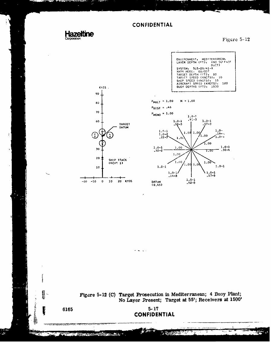
CONFIDENTIAL
Cowratm Figure 5-12
ENVIRONMENT: MEDTTERRANEANLAYER DEPTH (FT)i (NO SU-F•CE
DUCT)
SYSTEMt SQS-26/41-XXMTR MODEM 8B/ODTTARGET DEPTH CFT)n 55TARGET SPEED (KNOTS)i 10
SniP SPEED (KNOTS): 15AIRCRAFT SPEED (KNOTS): 120
KNDS 1 OUOY DEPTHS (FT): 15)0
90
80 PMULT = 1.00 M 1.00
PBIST = .46
70 =MONO = 1.00
1.0-'•
60 1.0-1 -3 1.0-1
TARGET .5 -3 .5-DATUM
1.O-1 1.0 1.0 .19-.,
ý41.0-2 1.00 0 .1.0-
.22-S' 1.011.-
1.00
30 1.0-1 1.00 1.0-1.32-2 o 1.00 .30-4
20 SHIP TPACK
(RCVr: 1) 1°. o ,0 1.00
10 1.0-1 . 1.0
S1.0-i 1.0-1.14-5 .17-5
-- •- 1 .0-1
-20 -10 0 10 20 KYDS DATUM .52-5
(0,45)
Figare 5-12 (C) Target Prosecution in Mediterranean; 4 Buoy Plant;No Layer Present; Target at 55'; Receivers at 1500'
6165 5-17
X -CONFIDENTIAL
F S- -?_ _ _ _ _ .7Z . . . . .... _-

CONFIDENTIAL
Haze Wnecooraho•n Figure 5-13
ENVIRONMENT, MEDITERRANEANLAYER DEPTH (FT)e (NO SURFACE
DUCT)SYSTEMt SQS-26/41-XXMTR MODE, B/OD'TARGET DEPTH (FT)i 300TARGET SPEED (KNOTS). 10SHIP SPEED (KNOTS)t 15AIRCRAFT SPEED (KNOTS), 120
KYDS BUOY DEPTHS (FT), 60
90
80 PIHULT = 1.00 N = I 1.C.
PBIST = ,39
PMONO = 1.00
1.0-1
60 1.0-1 .11-3 1.0-1
TARGET .0- I .03-3DATUM
1011.00 .01.0-1.99-1 1.0 97-4
30 1.0-2 1.0-4
1.00
20 SHIP TRACK
(RCVR 1) 1.0-1 1.00 1.0 1.0-1
10 ;ý/t1.00 1.00ý
1 : ' • •1.0-1 1.0-1
-20 -10 0 10 20 KYDS DATUM .99-1(0,45) .42-5
Figure 5-13 (C) Target Prosecution in Mediterranean; 4 Buoy Plant;No Layer Present; Target at 300'; Receivers at 60?
6165 5-18
CONFIDENTIAL
_ •=•. -- •.• • : -_. _

CONFIDENTIAL
c~ot• Figure 5-14
ENV!RONMEVT7 MEDITERRANEAN
LAYER DEPTH (FT), (NO SURFACEDUCT)
SYSTEMs SQS-26/41-XXMTR MOD,: rP., O01TTARrET D->ITH (FT)s ',00TAR.jET .PEED (KNOTS)i 10SHIP SPEED (KNCTS)i 15AIRCRAF
T SPEED (KNOTS), 120
KYDS BUOY DEPTHS (FT)a 1500
90
80 PMULT = 1.00 M = 1.00
PBIST ý .93
70 PMONO = 1.00 1.0-11.0-1 1.0-2 1.0-11.0-2 1.0-3 1.0-2
60 1.0-3 1 0-4 1.0-3
TARGET .98-4 2.0-4
DATUM)1.o 1 ,1.0-1
f,2- 1..o - . 0 .78 -2~14 .- 210 . 1.0-31.0-
01.00 10-11.0-1 .o.05-2
30 ;3-2 1.00 ,_ _ .80-4.31-5 1.00 .32-5
1.0020 SITRC'1.0-1 -- y*, 1.0-1
SH R ACV 1) . 08-2 1.0 0 1.00 .07-410 V 1)99g-5 .00 1.009-
L + 1.0-1 1.0-1
-2 1 02 YS .34-2 991 .07-3-20 10 1020 YDS.07-3 .9- 32-4
DATUM 1.0-5 . 1- .00-5
(0,45) .17-4
.5-
f Figure 5-14 (C) Target Prosecution in Mediterranean;. 4 Buoy Plant;No Layer Present; Target at 300"; Receivers at 1500'
[ 6165 5-19
CONFIDENTIAL

CONFIDENTIAL
HazeiirbCorporation Figure 5-15
I-ENVIRONMENT, MEDITERRANEANLAYEF DEPTH (FT)s 100SYSTEM: SUS-26/41-XXMTR MODEI BbL'/ODT (2ND CZ)"TADOC DEPTH (FT)z ?00
TARGET SPEED (KNOTS)s 10SHIP SPEED (KNOTS)s 15AIRCIA-T SPEED (KNOTS)i 120
KYDS B EUOY DEPTHS (FT) 3 1500
90 TARGET
DATUM PMULT = .77 M = .79
6"BIST = .77
70 PMONO = .60 .23-3
.53-5.26-2 .17-6
9 8 ~~. -3.1-
50
.09-L. .84 .86 .19 .09-140 .10-3 .18 .58-7
.,63
1.0- 1 1.0-130 1.0 2 - 1
.28-3 1.00 1.0-7
1.0020 1.0-1 1 V 1 01
SHIP TRACK 1.0-2 1.00 1.00 10S.1O010 (RCVR 1) .98-3 .03 1.0 1.G
1.0-9 1.00-1 1.0-1
1.00- 99-7t 1.00-8 1 1.0-8
1.00-9 .99-1 1,0-9-20 -10 0 10 20 KYDS DATUM .10-2
(0,70) 1.0-81.0-9
Figure 5-15 (C) Target Prosecution in Mediterranean Using Second CZ
6165 5-20
CONFIDENTIAL-S

CONFIDENTIAL
• Camtion
(C) Predictions of the results for operations analysis utilizing an SQS-23/41-X system in the Mediterranean have already been described inSection V-2. The system will perform well bistatically, but becauseof the limited performanc e of the 2 3 monostatically there is less like-lihood of obtaining localization using this system.
(C) Although operations analysis was not run for this system, it is clearfrom a comparison of typical. buoy coverages that the SQS-23/41-Xsystem in the Mediterranean will have performance equivalent to theS08-26/41-X system in the North Atlantic.
I
6165 5-21- CONFIDENTIAL
-47 61 1--MIN
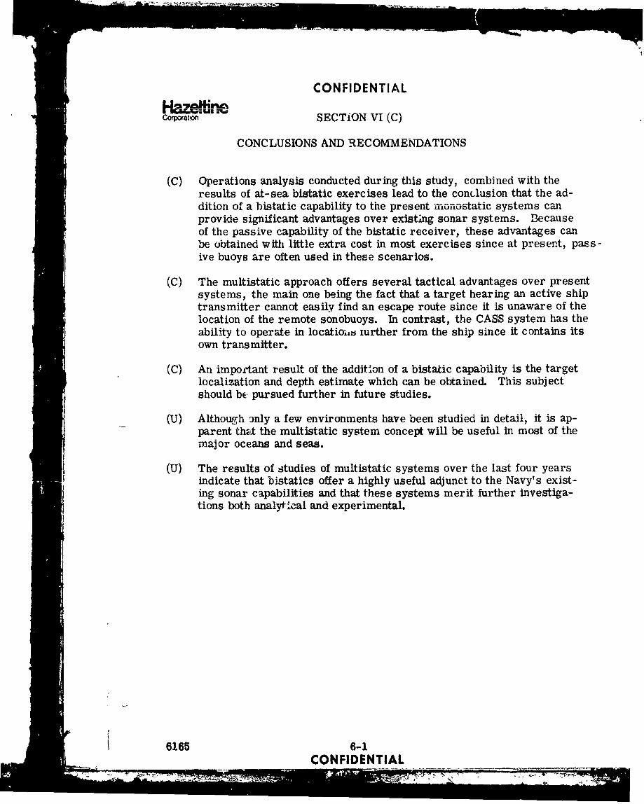
CONFIDENTIAL
Corporaon SECTION VI (C)
CONCLUSIONS AND RECOMMENDATIONS
(C) Operations analysis conducted during this study, combined with theresults of at-sea bistatic exercises lead to the conclusion that the ad-dition of a bistatic capability to the present, monostatic systems canprovide significant advantages over existing sonar systems. Becauseof the passive capability of the bistatic receiver, these advantages canbe obtained with little extra cost in most exercises since at present, pass-ive buoys are often used in these scenarios.
(C) The multistatic approach offers several tactical advantages over presentsystems, the main one being the fact that a target hearing an active shiptransmitter cannot easily find an escape route since it is unaware of thelocation of the remote sonobuoys. In contrast, the CASS system has theability to operate in locatiois iurther from the ship since it contains itsown transmitter.
(C) An important result of the additlon of a bistatic capability is the targetlocalization and depth estimate which can be obtained. This subjectshould be pursued further in future studies.
(U) Although ,nly a few environments have been studied in detail, it is ap-parent thal the multistatic system concept will be useful in most of themajor oceans and seas.
(U) The results of studies of multistatic systems over the last four yearsindicate that bistatics offer a highly useful adjunct to the Navy's exist-ing sonar capabilities and that these systems merit further investiga-tions both analytical and experimental.
6165 6-1CONFIDENTIAL
• ,,-' " • , I I I -I

CONFIDENTIAL
APPENDIX A (C)
PART I
CONWOY SCREENING IN THE NORTH ATLANTIC
bvir• 3Ship SubFigure ment Mission Datum Buoys Course Course XMTR A/C
A-i N..A. Screen 00 -60' /Sraight\ 1800 26 BBIODT HeloA-2 30 0 10 knotsoA-3 660 knots 250' /A-4 Xbdixidual Receiver Performance Summary)A-5 ' " 0_ 2-60' / Strai4ht CPA ) 26 BBIODT HeLoA-6 300 at" I 10 knots"A-7 0° " knots ) 250' /A-S " ( "lt~Idua1 Receiver Performance Summary)A-9 0 2-60' Straight 1800 26 B0/ODT HeloA-10 30 0 , // ot.A-1i 60,0 Moto 250'
A-12 (UdihMual Receiver Performance Summary)A-13 00 2-6?' (Straight\ (CPA 26 BB/ODT HeIoA-14 30. 0 - at 15 ! 6 knots|..A-15 .. . o \ r,, / \ 5' ..A-016 250'A-17 (Ind~idual Receiver Performance Summary) 0SA-0 . 0 1-69' Straight 180 BB/ODT HeloA-18 . .0 " at 15 1 knotsA-19 " 600 \ knots 250'A-20 " (Indvidual Receiver Performance Summary)A-21 0 0 1-6 10' Straight CPA 26 BB/ODT HeloA-22 3 0~ at15 10 knotsA-23 560 knots ) 20'A-24 " "(alvid.&I Receiver PerforA•ance Summary)A-25 5,15, 25 1-60' 0 Rel I CPA 26 BB/ODT HeloA-2 " ". 91000 Re. o .knotsA-27 ... " 90 Rel. . 250'A-28 .. . (Jndivldul Receiver Perforzhance Summary)A-29 .. . 5, 15, 25 1-60' Rel. CPA 26 BB/ODT HeloA-30 .. .45° Rel. 10 knotsA-31 .900 Rel. 400' "A-•2 (budividual Receiver Performance Summary)A-3 " " (Individa~l Receiv2r PerforW=nce Summary)A-34 " 5, 15, 25 1-60' 45 Rel. CPA 26 BB/ODT Heb)A-35 " " (Individual Receiver Performance Summary)
- i
6165 A-1
CONFIDENTIAL
- -- -- --
------- -- --

CONFIDENTIAL
Haze~r*Figure A-i
kyds
Submarine 7Trac'ks ~ ~ L/ /
Sub Speed
Course 1800Remote Sanobuoys 40
Target Belowthe Layer
01 MISSION CPD
ITrack Average Case
"20 goo0 1.00 1.00--
Rcvr 1 On Ship
-20 10 20 kyds
6165 A-2
CONFIDENTIAL

rr Wu -CONFIDENTIAL
HazeffineCirxpation Figure A-2
70.,
kydls Submarine 7'60 Tracks
Rcv 2
501Rc 3
Remote •Sub Speed
Sonobuoysf 10 knots40 Course 1800
Target Belowthe Layer
30
MISSION CPDShip 5 Track Worst
0 Track Average Case20 5 00 1.00 1.00
450 .98 .95900 .96 .80
10
Rcvr I on Ship
ShipTracks
10 20 30 40 kyds 50
6165 A-3CONFIDENTIAL
no" - p.f ta-s rS••: I I• @ .- G ,m = = _ - . . : : t- ." - ' ". _-' = _ _- _: _: - = -- -,, . . ' ' '- p ,- . . .

CON FIDENTIAL
Kazdfir*Figure A-3
00
10
E- >-1'-~U1
04 00
.44
6165 A-4CONFIDENTIAL
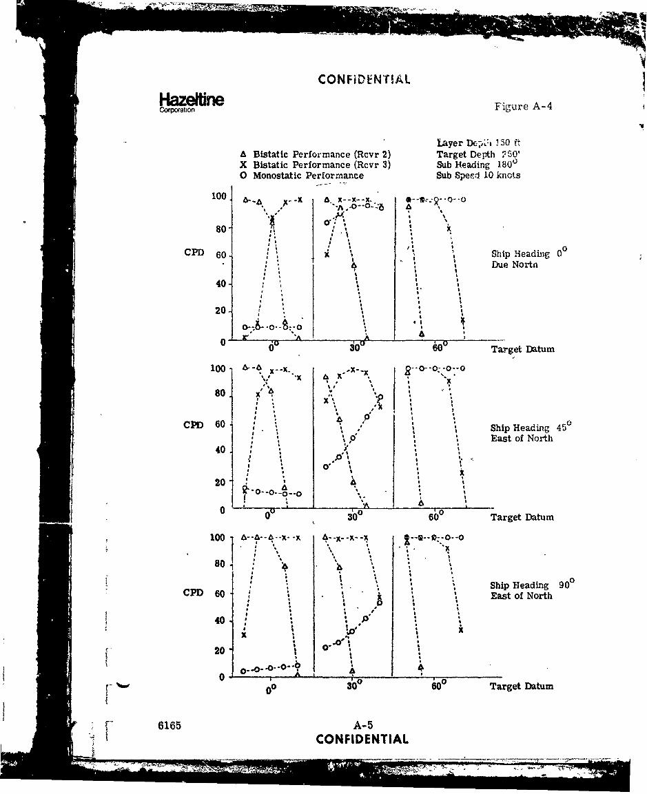
CONFiDENTIAL
CoHpaat on Figure A-4
*Layer DcI--Lh .3 0 ftA Bistatic Performance (Rcvr 2) Target Depth 250'X Bistatic Performance (Rcvr 3) Sub Heading 1800O Monostatic Performance Sub Spes.i 10 knots
I100 _x.
80 08P 01 : * : 0
CPD 60. Ship Heading 06 Due Nortn
40-
20. a
0 A
030 60 Target Datum
100 • -X--L. ----',. "x I, I x
80
CP 60" Ship Heading 45°CD 40o"a East of North
* 0 '40.
20- : ,a a,2"O-0-0- I 0""
* a
0 0 600 Target Datum
80, : a
Ship Heading 90CPD 60a a ,i 6 .8 .East of North
, a
SO" -0. -0- -0..? 140 A, a
•- •"00 i0° 0 Target Datum
S••"6165 A-5SI CONFIDENTIAL
* an " '' • = =
_ _n n__ _ i-il l I_ l iI I I I I I

CON FIDE~NTIAL
HazeffineCaor~ation Figure A -5
/ / 1kydj
\TralI4
R xr x vr
.50
%iib Speed10 knots
Remote Sonobuoys Course CPA
/ -Target Below-40 the layer
0
30 MISSION CPDShip 5 Track Wo'rst
Track Average Case
45 0 1.00 1:0090 0 1.00 1.00
72
+50
± Rcvr 1 on Shin
1 ~/'~hipTracks
-20 -10 1020 kyds
6165 A-6CONNiDENTIAL
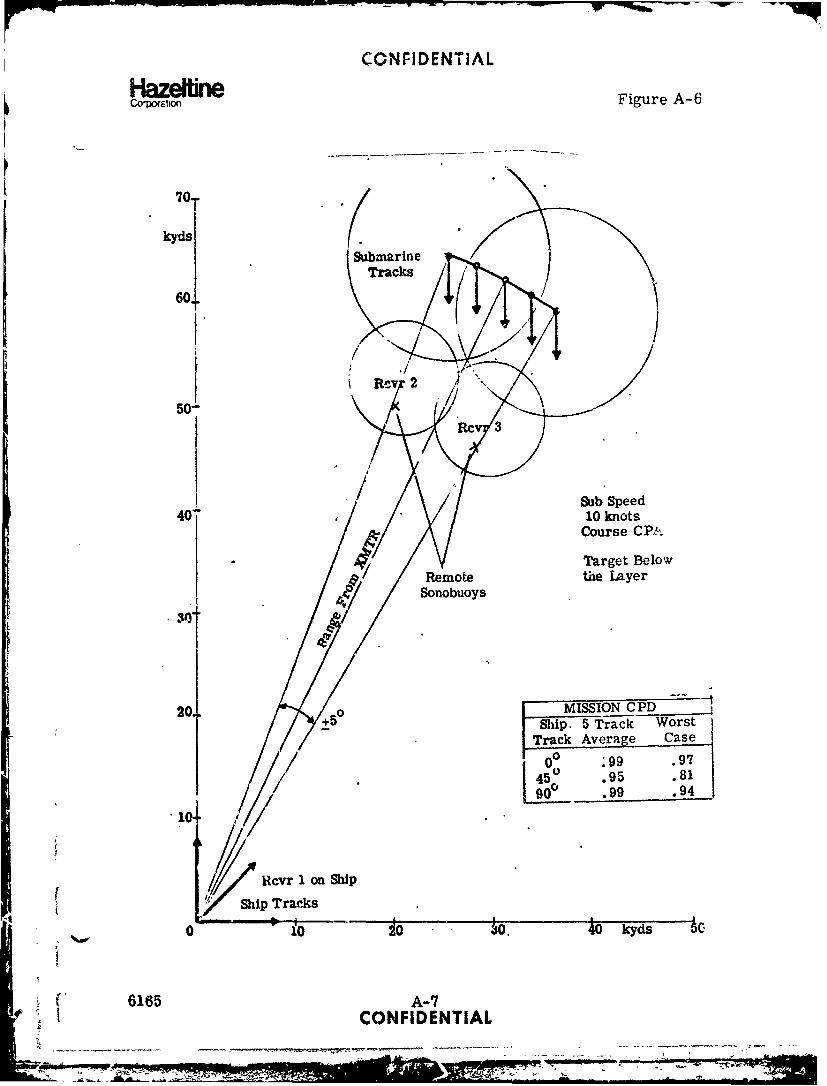
CONFIDENTiAL
Haze WineCa'orsbon Figure A-6
Submarine (IIC 2
Sub Speed
Course CPA
Target Below
20. MISSION CPD+50 Ship. 5 Track Worst
Track Average Case
0 99 .9745 .95 .81
Rcvr 1 on Ship
ShpTracks
0 10 10 J10. 40 kyds 5c-
46165 A-7CONFIDENTIAL
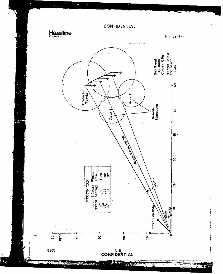
CONFIDENTIAL
HazeIrnCorpoation Figure A-7
<0
U H
cd U
0O -. 0
0)0
-00.
04
J : 00
0 cd 0 0 0
6165 A-B-CONFIDENTIAL

CONFIDENTIAL
HazemneCorporaton Figure A-8
Layer Depth 150tA Bistatic Per!ormance (Rcvr 2) Target Depth 250'X Eistatic Performance (Rcvr 3) Sub Head.ng CPA0 Monostatic Performance Sub Speed 10 knots
100 ~ -x 8 ~ -~
CPD W Ship Heading 00
it~ /Due North40 0 ,
"~ .0"
20 040I -
x
o 00 3000 0o WOO I Target Datum
100 *-- S--Q-*--- €. - -X 6--"-. x -x100- '. " .;
80 1 14%Io., .,,.,
CPD 60 Ship Heading 45cCPD6O iEas4 of North
40 U '
20 O"O-0-14 0-1 1.
0 6030 i Target Datum
100 x- --- x--x
80 i
. CPD " Ship Heading 90
I I East of North5 I* I
20
f 0 ° 3303 60° Target Datum
6165 A-9CONFID-ENTIAL
+- -: - _-_ • + + . , . . ... -. _- -' l b . m . ,. . . . . . . , . ,, .:
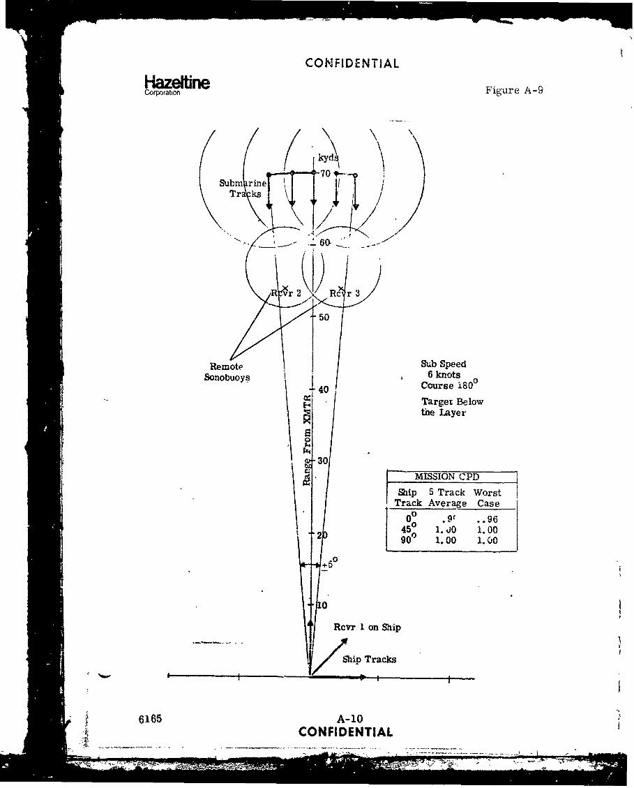
CONFIDENTIAL
Corporaton Figure A-9
kydj
Subm rineTr ks\
7
50
Remote Sub SpeedSonobuoys 6 knots
±40 Course 1800Target Belowthe Layer
5.0
930MISSION CPD
Ship 5 Track Worst
Track Average Case0° .9c .. 96
2 45° 1. A0 i.0090 1.00 1. c0
:0
Rcvr 1 on Ship
Shin Tracks
6165 A-10"CONFIDENTIAL
-7 , = 0 -0"'U-*

CONFIDENTIAL
HazeltineCoxqalian Figure A- 10
70
60-
50
S•-• Sub Speed
40 R.6 knot s
40o o• , .•/ /Course 1800
Sonobuoys ArlTarget Below
the Layer
S-MISSION CPD"Ship 5 Track Worst
Track Average Case20 +50 0° 1.00 1.00
45° 0 99 .999._0° .97 .84
10
I0
10 2C 30 40 kyds 50
6165 A-11CONFIDENTIAL
I - ' . - • -. .... - ...-L ___ _, "- .... - .....SI mIi~ i M ii-iI

CON FIDENTIAL
Hazeffr*Fiuene-CorpoationFiueA l
00
9.0
0a W 000
616 CONF 1b cT A

CONFIDENTIAL
HazetUneCorporation Figure A-12
Blayer Depth 1506A Bistatic Performance (Revr 2) Target Depth 250'X Bistatic Performance (Rcvr 3) Submarine Heading 1800 Monostatic Performance Sub Speed 6 knots
100 X--X. &--a ,--•--:f--4 -- : --o
8044 2
4, 6 .9-11p Heading 0°
S I I: * Due North
40 ,
20 A' x ;* K k
(i6 0° 60 d Target Da:,-um
4 4 I
0
S 60 Ship 4eadirig 450
; ttff"East" of Worth
a I "I
C I I
0 0
T r
00 300 60° Target Da.urn
10•~ ~ ~ ~ ,.X_.•. .-- Z--x ,-,--=-o
,Ship Heading 900
Sx !East of North
36t Tg D m
p,0J,,i-Io"
6165 A-13CONFIDENTIAL
" -g '
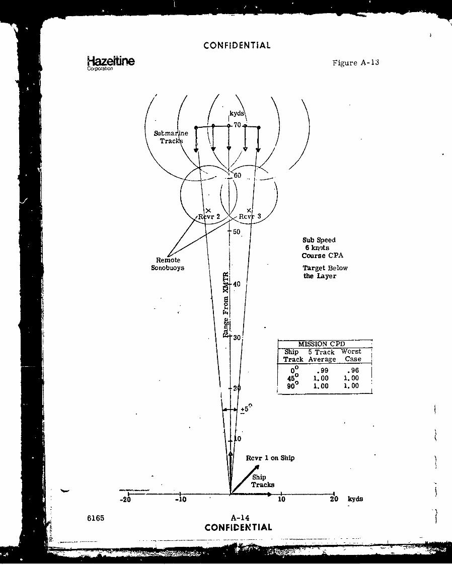
CONFIDENTIAL
Hazeri Figure A-1Corporation
j
(Stima *ne 00l
Track
I I/
.,R r 2 Rcv 3
150" .Sub SpeedI 6 krots
Remote Course CPA
Sonobuoys Target Below
ri 40the layer
0
=,0
MISSION CPD
k Average Casei
00 .99 .96
45 1.00 1.0090 0 1.00 1.00
+5
0
Rcvr 1 on Ship
Ship
Tracks
S-20 -10 10 "120 kyds
6165 A-14CONFIDENTIAL
a~t•'•.••. . , • - , . • •.•, t-
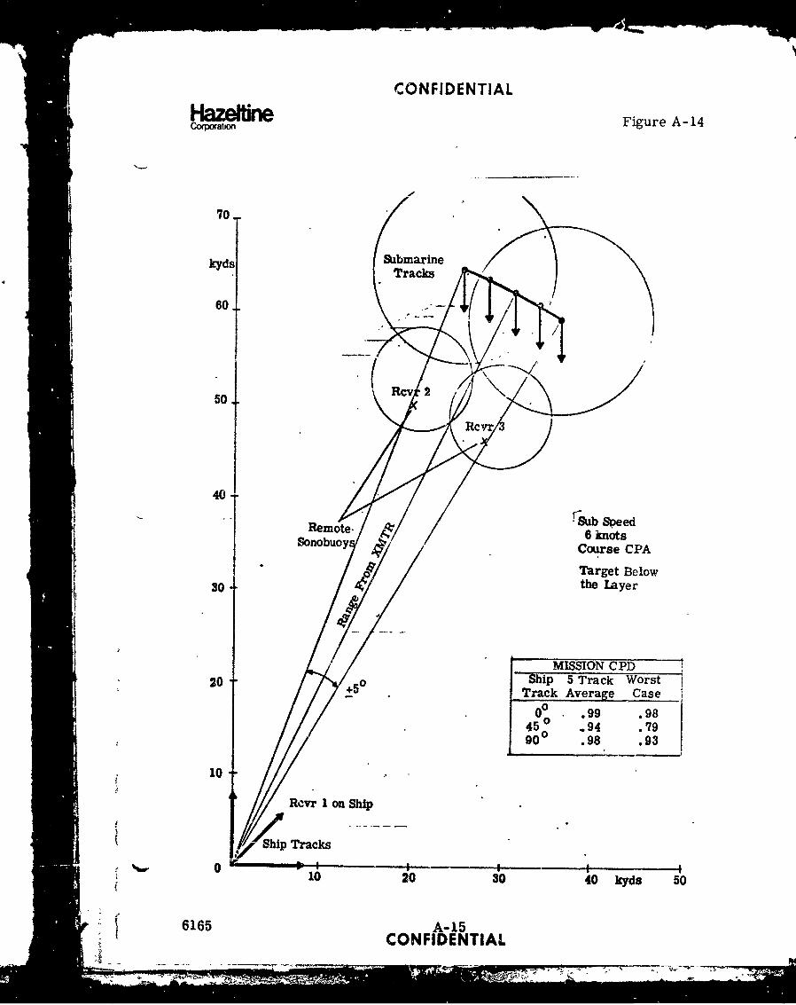
CONFIDENTIAL
H zefltn Figure A-14Corpoatio
70.
Icyds %zbmarine
60.
50.
40-
Remote, f. r5b Speed/' 6 knots
Sonombuoy Course CPATarget Below
30-thlae
20 +0Ship 5 Track WorstTrack Average Case I
10
Rcvr I on Ship
Ship Tracks
010 20 30 40 kyds 50
6165 A-15CONFIDENTIAL
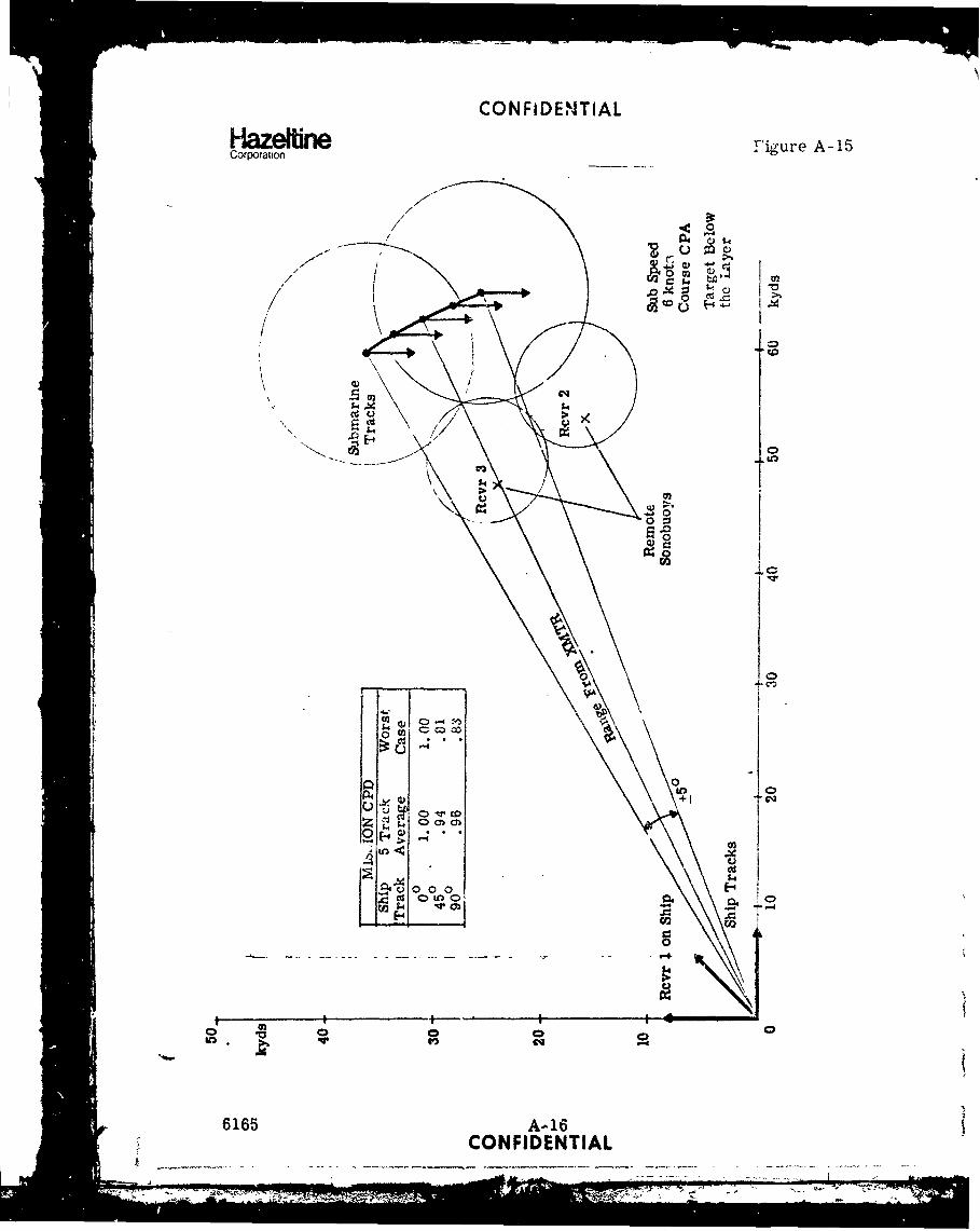
CONFI~D E NTI AL
Hazeftine Figure A-15Corporation
10
040
0,
01
001-4 > .
co
SQ4 0 0 0 0
6165 A-i16CONFIDENTIAL

CONFIDENTIAL
Co8ation Figure A-16
orayer Depth 150.A 13lstatic Performance (Rcvr 2) Target Depth 250'X Bistatic Performance (Rcvr 3) Sub Heading CPA0 Monostatic Performance Sub Speed 6 knots
100 x--x . x x x 0-- 0-0- §
ArA
80" \" A-"-6-A X80 * I. : ,
" ~00CPD 60 "1 • Ship Heading 0
Due N4rt4 0 * I S "
$ *
20 , .o- rO'/O-~~~0ý "O O -0- %,^'1#ý -0 -0--
0 0 300 600 Target Datum
1001 0--o--o X- x.It
st 180 x
CPD 60- Ship Heading 450* ,East of North
40 A200 9 I
do odo 0 Target Datum.100. -4- - --- A--x--X- , -
80 \ °
CPD 60 Shi," Heading 900East of North
4o o_:o0- ., ... tI I t
I *I
60 300 0 Target Datum
6165 A-17CONFIDEN (IAL
= - .,. ... .~

CON FIDE NTIAL
Corporation Figure A-17
kyds
(SubmarineTracks
Bistatic50 Rcvr
Sub Spee~d10 knotsa
* Course 18040 Target Below
* the. Layer
- 0
MRISIQN CPD
+50 Ship 5 Track WcrstTrack Av'3rage Case
00 .83 .592 45 0 .91 .56
90 0 1.00 1.00
Monostatic Rcvr on Ship
Ship
_____ ___Tracks
Nw20 10 10 20 kyds
616b A-. 18CONFIDENTIAL
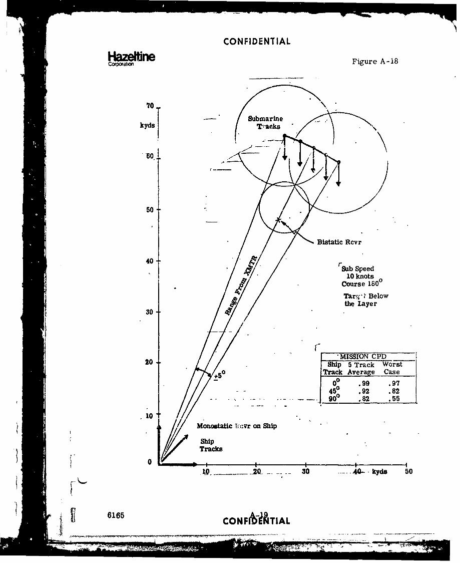
CONFIDENTIAL
Haze WneCopodtlor Figure A-18
70.
T Submarinekyds Vak
50 -1
Blatatic Rcvr
40-'Sub Speed
10 knots
Course 1600
Tar% Below
the !ayer
30-
20 ____ M ISSION_________________________
20Ship 5 Track Worst
+5 0Track Average -Case
00 .99 .97
Monostatic ", ,tvr on Ship
--2Q-. 30 -40- - kyde 50
6165 CONNUATIAL
______________- 7-77-
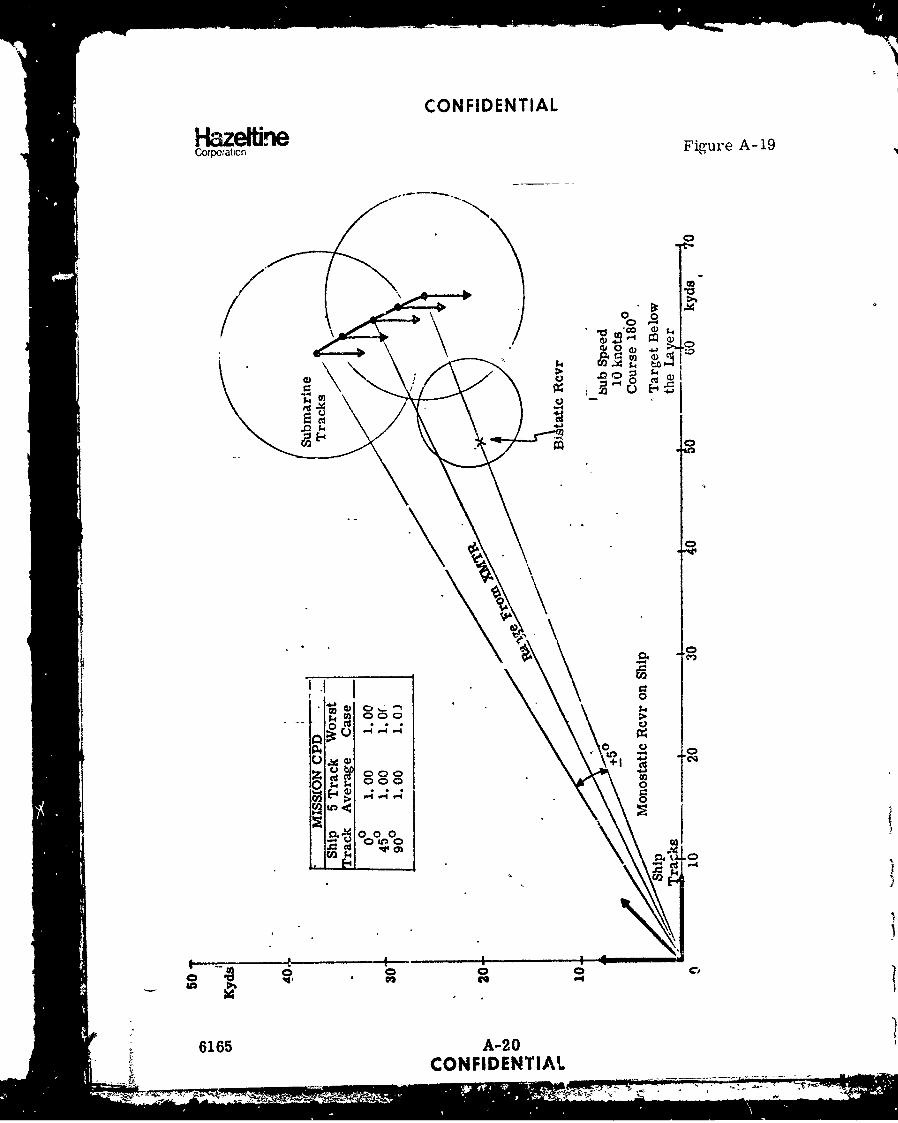
CONFIDENTIAL
HazeitreCorpo~ation Figure A-19
00
c0 00-
0 c
~14
+ 4. 0
k 0000
E-4->
4~14
I mr-2i; Ci

CONFIDENTIAL
Haze~r*nCortat•on Figure A-20
lAyer Depth 1506X - Bistatic Performance Tafrget Depth 250'0 - Monostatic Performance Submarine Heading 180°
Sub Speed 10 knots
i I ' I1001 - X-S0.-
cX 01' tShip Heading 0
* Due North40 I* U
* S
200-0-0-0.O,-0 x
0. -o 30 6t0° Target Datum
100 '- -- x---x., -.- -o- -080.
1 Ship Heading 45': CP 60 '•.East of North
40-
I ShpHedn
0; ',
_0_'" o. " 3f~60' Target Datum
if 6165
• , Ship Reading 90°
.•- .
CPD 60', . East of North
0 oop 360 60° Target Datum

CONFIDENTIAL
Cooaze~r~e Figure A-20
layer Depth 156'X - Bistatic Performance Target Depth 250'0 - Monostatic Performance Submarine Heading 180°
Sub Speed 10 knots
X:-o--o--o--100 ..- 0- x,--
"x
I 6
Cl 6 Ship Heading" 00, ; Due Worth
40'
20
0 .6 00 6o0 Target Datum
100 I---AX X,-.---
I- I
I ,
'. Ship Heading 450
CPD 6 ,0 *East of North
CP 0 'kX
40-
0. x
201 0.
0 300- 6V0 Target Datum
100 -- x-- x--x. *.-,-o-
x" "x
80t
, Ship Heading 90
D60 East of North
CPD 60,'
40"O I
20 -o
80 80] 'Ship Heading 900
00 300 Target Datum
(6165A-1 CONFIDENITIAL
SMIR --
40o-
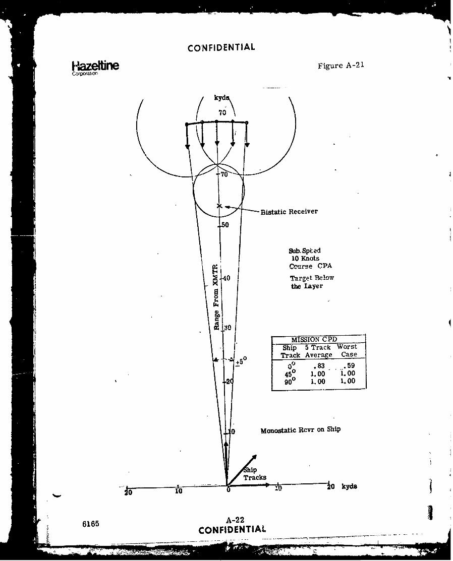
CONFIDENTIAL
Haze beCorpoattonFigure
A-21
kyd
Bistatic Receiver
Sub. Spited10 Knots
Course CPA
40 Target Belowthe layer
MSSIO CPI Ship 5 Track Worst
+50 rack Aver e Cs.83-.0 045 1.00 100
-27 900 1.00 1.00
0 MonostatiC Rcvr on Ship
6165 A-22
CONFIDENTIAL-
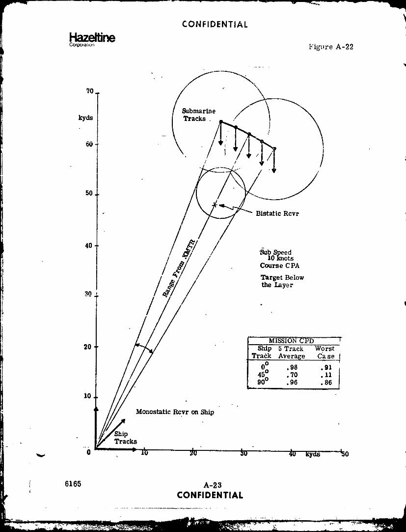
CONFIDENTIAL
HazetireCoraijao Figure A-22
70T(Submarine
50.
/Bistatic Rcvr
40 uS
/' _, / 'b Speed/ 10 nots
Course CPA/r/ I /Target Below
the Layer
/ .
MISSION CPD20 Ship 5 Track Worst
Track Average Case4
0° .98 .91450 .70 .11
_900 .96 .86
10
Monostatic Rcvr on Ship
ShipTracks
3LU I nI" ý
6165 A-23
CONFIDENTIAL
-,-.---'il A jýz

CON FIDENT IAL
HazeffineCorporation
Figure A-23
U, U
+ce)
$ m'4 0 0cd C
+1 P4 0
U
(D~ 0C0.-
El ) 1 * .0 0
Q 0 U 0 0S-4
6165 A2
CONFIDENTIAL
Ws, 7 -:

CONFIDENTIAL
o n e Figure A-24
ayer )Depth 150'
X Bistatic Performance Target Depth 250'0 Monostatic Performarce Sbmarine Tactic CPA
Sub Speed 10 Knots
100L X-.X- -x- -x, o--oo--.o-
80
CPD 6(0' I Ship Heading 0
40 x Due North
21 --_O--O--O-'° 0,'
0o00 600 Target Datum
10• ,--.--e-•-.--e -x x.-X100 -2 X--,- - -X- --E
CPD S0- -;hip Heading 45°
t East of North
40x :.
I2'
20 0"O--o-1o
0 i) 0° 60° Target Datum
I00a X--- -• --- X-.--0- - . , x - I t
8O 5
Ship Heading 90SEast of North
CPD 60 •
40
2 0.- 0
i0
I I
6165 A-25S~CONFIDENTIAL
S
== •....• . .... ..6
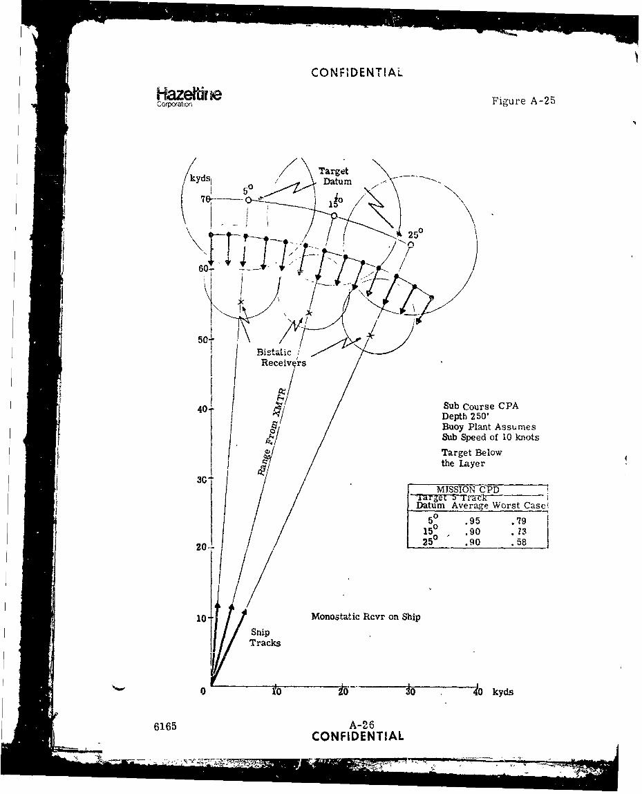
CONFIDENTIAL
HazeffineCorporation Figure A-25
Target/kyds, Datum ,\ m-
-25°0
+F'Fr] 7 -h. /
60o 1
50-L/'BistaLicReceiv rs
40 -' Sub Course CPA
I Depth 2 50Buoy Plant AssumesSub Speed of 10 knots
Target Belowthe Layer
MISSION CPDi T~~arget 5 rc
iDatum Average Worst Casei
5 0 .95 .7915° .90 .73
20 25 .90 .58
0 TanMonostatic Rcvr on Ship
Snip _ _ _ _ _ _
0o 10 1 o .... . 40o kyds
6165 A-26CONFIDENTIAL

CONFIDENTIAL
HazelfrnCofpation Figure A-26
Target ,
Datum
50.. 150
Sub Course CPA
Depth:250'
S40 •'Sub Speed of 10 Knots
S~Target Belowthe Layer
-
30/
MISSION CP.D.Wrs
eceWoest
Datum Average Case
205° a I.00 3. 00
2015° 0 I. 0 0 .0025D .00 1.00
400 20 SOo40 kyds
'"6165 A-27 MSNDCONFIDENTIAL

CONFIDENTIAL
Hai.eltbneCorpora.on Figure A-27
kydS 0 \Target
Bistatic
50- ReceiverLs
Sub Course CPA
Depth].:50'Buoy Plant AssumesSub Speed of 10 Knots
40// Target BelowC: ' / tthe Layer
MISSION CPD/Target 5 Track Worst
20// Datum Average Case
5 0 1:00 1.0015° 0 1.00 1.00250 1.00 1.00
10
ShI/ Monestatic Receiver on ShipShip • -•.
Tracks0 10 2. 30 40 kyds
6165 A-28CONFI)ENTIAL
It7

CONFIDENTIAL
HazeffneCaotation Figure A-28
lAyer Ibepth 150'X Bistatic Performance Target at 250'0 Monostatic Performance Submarine Tactic CPA
Suiumarine Speed 10 knots
10010 X-"x- -X, F- .x.-,X X-- X-- X
80 - x•
CPD 60 0SShip Heading 0°with Respect to
40 Tfarget UDatum
20'
0 Ao 15o Target Datum
100 1 l-e -- e -l e--e -I e e-e--e -
80
CPD 60 Ship Heading 450
with Respect to
40 Target Datum
20
0 5o • i0 i-5° Targei Datum
100 " x--x--x--x--K X--X--X--X--X X--X--X---K--.
8 .. 0. O0o"80 "o.o .".
CPD 60 Ship Heading 900with Respect to
40 Target Datum
20
0 • 5150 Target Datum
6165 A-29
CONFIDENTIAL

CONFIDENTIAL
HazootionCHaoraton Figure A-29
5o c.q,5 0 Datum
I 5
Bistaic // 1j
Receivers
Sub Course CPADepth 400'
4(* . Buoy Plant AssumesSub Speed of 10 Knots
Target Belowthe Layer
30t
MISSION CPD
Ft-iargct 5 Track Worst
Datuvm Aerage Case
020 5 5° .55 .11
15 .53 .11250 .49 .10
1(4 iMonostatic Rcvr on Ship
I Ship Tracks
0 1• 20o -kykd
6165 A-30CONFIDENTIAL
[ L ----- -

CONFIDENTIAL
HazefirneCoqxwlionFigure A-30
(kyde Target
4d 5o ~ Dqur t _
/ / 250
BýstaticRecei rers
50-
Sub Course CPADepth 400'
4&' Buoy Plant AssumesSub Speed of 10 Knots
I Target Belowt~v the Layer
30..AMISSION CPD
ITarget 5 Track WorstDatum Average Case
0150 1. 00 1.00
20- 25 10 1.001
ShipTracks UMonostatic Receiver on Ship
6165 A-31CONFIDENTIAL

CONFIDENTIAL
HazdeineCorporation
Figure A-31
/ Target
Corporatto
70-
S( ,25°77
60-r -
Btst/tic
5 Receivers
Sub (1,lrse CPADepth 4ý,'"0Buoy Plant kzsu.iesSub Speed of ',*. Knots
Target Belowthe layer
3 '',!1 CPI7
Datumu Average Cas.
0 -
5 .95 .98150 .98 .96
/ 250 .97 .90
ShipTracks ,
0 t0 20 30 4 k"yds
6165 A-32
CONFIDENTIAL
L - -....... ;,;i ....- • ~ --- #> . .. "-... ...

CONFIDENTIAL
HazeltineCO•,rat Figure A- 32
lAyer bepth 150'X Bistatic Performance Target at 400'0 Monostatic Performance Submarine Tactic CPA
100
8 x.. ,,* "
81 A
CPD 601 , ,Ship Heading 0
, S ,vwith Respect to0 Target Datum40- •
20 !'
-0-0-0-6-o 0 -0-o----o-- 0- -o- -o-1o;
0o 10 2e° k Target Datum* I
1001" 0. -0-
80
CPD 60 Ship Heading 450
with Respect to
40- Target Datum
20'
° 25 . Target Datum
100 - --.- I - .
I /
80- x""-o. 0."- '• "
800
CPD 60] "Ship Heading 90
6k with Respect toTarget Datum
401
201
0 1 0$5 i5p Target Datum
S6165 A-33• CONFIDENTIAL
, ,:: • . .... -,.---- -. • • - . ..... ......... • ! _ .
•,. :• :.: '- •'..•.•. • -' - :..-o"•vI - • -•• .. •: • .. _ -% 80_.....

CONFIDENTIALHazefiCofxation Figure A-3S
layer Depth 1501X Bistatic Performance Target Depth 250'0 Monostatic Performance Ship Heading 450 with
Respect to Target Datum
100 •--®-.•g-o *-*4-•-o e0 -- •-.t I
80 * I1 6
CPD 60 Sub Speed6 Knots
40
20,
0 0o - 250 Target Datum
80
60 Sub Speed10 Knots
40
20O
0u 150 2J50 .Target Datum
100.80 --0"
8 0.J ifj 0
60 . Sub Speed*'15 Knots
40'30, " "
20 5
0 t Target Datum
16165 A-34TA•, CONFIDENTIAL

CONFIDENTIAL
Figure A-34
' / •,,•Datum
70
x x x/
Sub Course CPABuoy Plant Assumes
40 Sub Speed Bet',,esn6 and 15 KnotsTarget Belowthe Layer
3/ /
MISSION CPDTarget 5 Track WorstDatum Average Case
20 50 1.O0 1.0015 0 1.00 1.0025 1.00 1.00
10
sip Monostatic Rcvr on ShipSTWacks
10 20 30 kyds
F 6165 A-35CONFIDENTIAL
, I n,7 -x -. - ,- ,.

CONFIDENTIAL
HazedneFuCorporation Figure A-35
lAyer flepth 150'X Pistatic Performance Target Depth 250'0 Monostatlc Performance Ship Heading 450. with Respect to
Target Datum
:10 ®-®- -- - -@-•- -- @--®--r-ge-
"'III
80
CPD 60 Sub Speed16 Knots
40
20
0 50 150 250 Target Datum
100 K- -•-®-X X-- - .- ®--
801
CPD 60 Sub Speed10 Knots
40
20°
0 55 250 Target Datum
NO0 -• X-x- -•--. ._ ... . - -- t .@ x- X- - x--AD---
80-0 .0 v0-'0- a'"
elPD: 60 J• Sub Speed15 Knots
40 -
20
0 ; 15o 5 Target Datum
6165 A-36CONFIDENTIAL
I "I I II I I I I I I i i i , , , , , '

CONFIDENTIAL
APPENDIX A (C)
PART 2
TARGET PROSECUTION
Envtron- ShpSubFisure mtent Mission Datum Buoys Course Course AM1T!r? A/CA-36 - ' Detedt Oo20 6-60' Z1g- Zag -0-3WO 2(; BB/ODT HeloA-37 1, 111 11A-38 It' 9 4500 Pel. 99 9A-39 It Rel.A-40 8 -60, Ral,A-41 Zig-ZagA-42 9A-43 "3-6"' ~ RocketA-44 0 0 Re!.A-45 1. 1 26 BB/VRACKA-46 .'-2-60'A-47 ' 8-60' Zg-a26B/T HoA-48 O"g 99 26 0 Re!. 'Bel
A-49 .Rl
A-5099' D,%-LegA:51 ' 9" 3-60" Rel. 26 BE/TRACK RocketA 52 2-60' .A-53 Med. 6-60, 26 BB*/'cIT HeloA-54 I. Dc-LegA-55 " '00ý3001 It ORel.A-56 1 6-1500' 11A-57 6-60' Zig- zag'A-58 ' 6-15001"'f ~~A-S59 4-6,. 00 Rel. ' 99A-60 '4-1500'
A-61 0 -55 4-60' '9
A-63 9 oo-soo, 4-60'A-64 14 4-15001A-65 0 o-3oo1 8-60' " 26 BB/CODTA-66 8-1500' ndC
A-El "4-60' ' 28 BB/COT
A-69 11 4-1500' 'A-70 0' 0~-3001 4-60' '
A-71 1. 4-1500'A-72 4 Q0
.6009 4-60' 9A-73 1. 4-1500'A-74 N. A. 0 f-. 5 5 1 5-1500' 11f CASSA-75 0 0.~300 1 ZIg-Zag ItA-76 99 600co '',9 99
*No Surface Duct pregent
6165 A3
~., ~ CO NFIDENTIAL -

CONFIDENTIAL
HazeffineC.:poration Figur(, A-,36
ENVIRONMENTI NORT" ATLANTIC
LAýER DEPT' (FT)t ý50
SYSTEM: SýS-2 '41-XXMTP MODE Pý•/ODTTAR'-ET OL r, (FT) 1 250TARPET SPEeD (KNOTS); 10
SHIP S,-ED (KNOTS)i 15
AIRCRAFT SPEED (KNOTS), 120
KYDS BUOY DEPTHS (FT)s tO
TAPGET
DATUM PM'LT = .80 M .83
0 PBIST = !69
PMC'NO = .46
o t, (-41.0-1.95-6 .09-1
.69-1 .12-5
"50 "1.0-7 .70 1.00 .99-5
40 .00 . -
S9 .99 .72-1
30 .9 .-- 48 .87-4.961.00
20 I RACK D.(RCVR 1) ,3P I =7,.-
.74- .4=.9 .84-410
.52-1 .49-10- 7 .--- -4 - 6-- .44-3 I .86-3-20 -10 0 10 20 KYDS DATUM .-
(0,70)
~MULT = -78 M = .81 MUT= .78 M =.78
91T.- .8ooT- .1ST = .80
S"MON .58 1.0-1.82-5
6- .97-1 1 .6 .691 .99-1 1.0-6 1.0-1
1.0.3 . .6 -8 :9.-2 .0.-4
.0-2 .0 .4 1.0-3 .96-1 .0 .779 10-4
.01-1 .07-1
DATUM TU
, (-6,70) (6A70}16,70
-96165 A-38 1
CONFIDENTIAL
- '3 j. -•--

CONFIDENTIAL
Co~ort~onFigure A-37(1)
ENVIRONME'%Tt NORT,i ATLANTICLAYER DEPTH. (FT). 150
XNITR MODE : E',/ODTTAPG`ýT DEPTH (FT)1 250TARGET SPEED (KNOTS)t 10SHIP SPEED (KNOTS)s 15AIRCRAFT SPEED (KNOTS), :d0
KYnS bUOy DEPTHS (FT)t 60
90TAFkGETDATUM PM'JLT = .81 Mi = .83
07 PBIST ,.68
p ,N .46
60 \60 x .95-6 .09-1.69-1 .27-5
50 .97-7 .70 1.00.3 10-
40 .97 .-
.00:30 .96-2 .6 .72-1
.6 .87-4
1.*00SH IP (Rc
(R~v .).99-1 .31.00 1.-174tCR1)1 '6 .521 .9 1.
28714-8 .59- .84-4
DATUM
PMULT =ML .8 8 .82 Mi .82
Pmo~ , .1 p ONO .581.0-1
1.0-1 _____ .86-5
.8987-087.0-2-
202. 011 .9- .-3 .1.69-24 DATU.1-1.2M
616 A-3883.7- .21.-COF2ENIA
CONFIDENTIAL
azerletne Figure A-37(2)Copor~aion
PMULT = .78 M .76
PBIST = .61MONO = .7 1.0-1
.93-1 .72-5
.07-6 "199-6
.77-7 .92-5
.41.00
•05-2 .92 .03-1.03-7 - .•08 . 9 '0 5- 5
i.0-2 1,80-4
.58 .9 13 .00 1.-
.98 .9
1.0.-. .96-11.0-1 .48-3.23-3
.79-3 .05-1
.98-3DATUM(0,70)
"DMULT = ,60 M =.68 PMULT = .81 Ni= .81
PBIST = .48 Pa31T = .64
M0NO = .51 .91-1 PMONO= .66 1.0-1 1.0-1
1.0-1 .66-6 .56-5 .93-5
.a1-i 1.0-6 .64-6
.74-1 15-1 .05-6\ , , •0 :09-6 .38- 1 .0-ik .,4 9- )7 \1.001 /,07-4
.03-2. .25 1.0-1 .92-1 .0 --
.0.3 .03- 10
5 .04-1
Sj .99-1 . 5-
.0 .90-3
DATUM .91 .- 3DATUM 3-(-6,70)
(6,70)
6165 A-40
_L• CONFIDENTIAL
1:0- i .0-2 .96..
_I~.7-
1.00•II •

CONFIDENTIALHazeitneCotxoat*.n
Figure A-38
ENVIRONMENTi NORTH ATLANTICLAYFR DEP'T,, (FT)s !-,0SYSTEM, S,ýS-26/41-XXMTR MODE, PG/ODTTARGET DEPTH (FT): 150TARGET SPEED (:%NOTS)s 10SHIP Sý'EED (KNOTS): 15AIRCRAFT SPEED (KNOTS)i 320
KYDS BUOY DEPTHS (FT)s 6090 TARGET
- DATUM
7 P MULT = .81 M - .83
PS1ST =.7570 MoNo =..52
m \/ 1.0-3to (1.0-3) . 08-1
S.87-750 +
(.80-1) *1.o0 1De .01-1
40 ,, 54ý 7B 1 -
.02
30 .19-1 .29 1.0-111-4 -. 06-2
/\20 .0
1.0-620- HIP TRACK
.98(RCVR 1) .88 7-110 -. 0-- . 98 1.00 .o-2
-20 '-10 0 10 20 KYDS .31-2 .59-1DATUM .95-2(0,70)
PMULT = .83 M = .84 PMULT .70 M = .72
PBIST -. 59 P8IST .49
PMOND 0 .61 PMONO .56
1.0-1 .99-1 1.0-1.14-3 1.0-3 .98-1 .99-7
.10-4 .99-1 .9-_433-3.10-7
.99-1 01.0 1.00 59-2 DO .00i .0-• .12-1 .14-3_ .03-.\0oo\0 0 / .o .82-7 .27-4 .\7 .86
.85 .91.0-.0.75-1 . 7. .99-. .04-1 .24.07-4 1.0 73- 2-240-6
.74 1.0-6 .1-.00 1.0 .. 19-117. 7 .. 14 47-1. -. 95-1. 5 9 .1 %. 0 - 2 1 . 0 -5
1.0-5/95.04-11
;3-1 I .08-2 .98-1 .10-1
1.0-5 .58-1 1.0-2 .06-1DATUM DATUM .72-ZS(-6,70)
(6,70)
61 35 A-41CONFIDENTIAL
* ~ *-T

CONFIDENTIAL
Corpoatior Figure A-39
ENVIRONMN'T NORTH ATLANTICILAYER [EPTH (0 1). 150;ysTrr " SQ5-26/41-X
T MODE, I lOuT
T4RbEI rCPTH (FT), 250TAR, ET ',PEED (KNOTS)t 10
SHIP SPEED (KNOTS)t 15
AIRCRAFT SPEED (KNOTS). 120
KYOS BUOY DEPTHS (FT), 60
9C, _ TARGE7DATUM
r6 PMULT = .69 M = .71
PB1IST = .57
7D PMONO = .33
50 .95-7 .01 .6
30 .97-2 1.000
20 SHIP TRACK 10
(RCVR 1) 1. 0-1,- .63 1.00 1.0-1.76-2 53 \.3,05-3
10 .05-3 .74-4
.29-1 .48.-3
-20 -10 0 10 20 KYDS DATUM .48 3 .52-3
(0,70)
tt
i
I
6165 A-42CONFIDENTIAL
I 1 1 I II I --' i-T
CONFIDENTIAL
Corporat*n Figure A-40
ENVIRONMENT1 NORTH ATLANTICLAYER DEPTH (FT)o 150SYSTem^ 1 SQS-26141-XXMTR MODE. BB/OOTTARGET DEPTH (FT), 250TARGET SPEED (KNOTS)1 10SH!P SPEED (KNOTS). 15A!RCRAFT SPEED (KNOTS), 120BUOY DEPTHS %FT), 60 J
S TA"RGET
90 + DATUM
/1 7ML .72 M4 .74
( P11ST = .72
PMONO '.33
96-6 .62-7
50 .32-5.08-6 .96 .62 .07-8
.38 .7 '19-9
.71-1 1.00 .71-1.63--4 1.CO .75-2
2i.0-5 1.0-9
20 b.IP TRACK 1000(RC\'R 1 1.0-1 .71 0 1.0-1
.!0-3 50 -1 1.0-210 1.0-4 .10-3
.29-1 .29-1-20 1 0 1 , ..56-3 .50-3 .06-2
-20 -10 0 10 20 KYDS .05-4 .57-3DATUM
(n,70)
6165 A-43
CONFIDENTIAL

CONFIDENTIALHazeffieCaopo~ation Figure A-41
E{ ROtrENT OTT ATLANTI(LAYER DE'TH (IT), 150SYSTEM, 3.S ,x/41-X
XMTR -ODE, P[E''ODTTAROET DE ýTh (FT), 250TAR ET SPEED (KNOrS): 10SH.' SPEED (,CTS), 15AIPCRAFT SPEED (kNOTS), 120
KYDS TARGET BUOY DEPTHS (FT), 60
DATUM
oML -70 M = .74
PBIST = .66
0 ©•M•NO = .46 1.0-1.11-6
.69-1 .90-7 .09-1.92-6 .31-8
0.15-5 10
40.
.72-1
1.0- .28-2
SHIP TRACK 1.0-920 (RCVR 1)
.99-1 <71.0-1I.05-3 .7 2 931.0-2
10 1.U -4$
521 -. 86-3
-20 -10 0 10 20 KYDS .19-4 .51-3DATUM(0,70)
PMULT '.91 M = .94 Pmu;= .88 M = .89
DBIST = .71 PBIST =.78
%MONO = .61 1.l PMONO .58 1.0-11.0-7
.97-1 .03-6 .69-1.(.99-1) 10 10-1
.47-1 .98 1.00 1.0-8 .\- . 1.00 .70-2
: 260 - 1 . 65 .8 7- .1 1- 1 'oO / / 2 -.00 7- .9-4.
1.89- 1.00 81.96-1 .1.4-1 1.0-1
.22- 2 .7481- 1 1.0-3 .01-2 .0 1.-2
* .e- . 94- .o91-4 .1\- . 78-.97- .814.10-3 11-
DATUM DATUM .97-3 .11-3
Z-6,70) (6,70,
6166 A-44CONFIDENTIAL

CONFIDENTIAL
Corpmtion Figure A-42(1)
ENV IRONMENT, NORTH ATLANTICLAYER DEPTH (F) 150SYSTEMs S .S- 6/q-XXMTR MODE, IIS/ODTTARGET DEPTH (FT)t 250TARGET SPEED (KNOTS). I0SHIP SPEED (KNOIS)i 15AIRCRAFT SPEED (KNOTS), 120
KYDS TARGFT BUOY DEPTHS (FT)s 60
DATUM
90
PMULT ' .92 M .96
P8IST = .74,
(7P)N = .46 1.0-1.1-31,0-4
60.69-1 1.0-5 .09-1
:4e.-4 I14-1.0-A3 .84 1.00 1.0-6
40'. 1.0 Z .94I-,0•.00
301.-2 1.000 .72-130 1.0-2 i0.
1.0 __L .0 -810-
20 SHIP RACK(RCVR 1) .99-1 1.00 1.0-1
11- 97 .9402-8
.49-1
N 1- --. 52-1 .89-e
-20 -10 0 10 20 KYDS .55-9 .69-6
DATUM .90-9
(0,70)
"PMULT - .92 M " .94 PMULT '.91 M = .93
PBIST s .67 P.IST = .55 1.0-1
PMONC = .61 1.0-1 PMONO k .58 .41-4 1.0-11.0-5 .64-593--4 .69-2 .99-1 .86 1.0%1-6
.71.44.28-4 .14-7
.141-5
784-3 .00 1.00 .70-1
.9 \2 .0-6 .. 44-4 .92 .00 ".04-6
•.00 .71
.90-2 .909$- .14-1 1.00 .23-1
1 ., 00 1.0-2 -/ ,9e .97-71.00 1.00
.7 6 .08 10- 1.00 1.0-1
.- 2-*.68-9 .95 .81
\ -".78-1.95- .8,-1 .11-1 .13-5S24-9 . 9.36-8 .96-8
DATUM DATUM .58-9
(-6,70) (6,70)
6165 A-45CONFIDENTIAL

CONFIDENTIAL
Corporation Figure A-42(2)
pMULT .92 M .93 PMULT ".J8 M = .90
7P3IST .7348 p 1.0-1
, .48 .72-1 .MONO = 50 1.0-4 1.0-11 .C-4 1.0-5 .08-4
.15-5 .50-1 .49-6 1.0-5
.82-i ' .11-1 .99-4 0 -
..0-3 ý.3 1.OO - .98-3 1.0 1.00 .7-6
i."0 1.0-6 .04- 1 .00 1.0-.96
.00- .47
, . - 1 .89-1 .06-1 1 .0i .47-101 -. 0-7 1.0-2 1.0 .0-7
-i.0
.92- .38 1.0 .32-8 .23- 1.0 "" 44 o .85 -1-
.34-1 .394 .8 .65-1
.93-1 10-~8 .24-1 1 .58-8
.15-9 .37-9 .33-9 .04-8 .01-1DATUM DATUM 1.0-9 ,43-8(-3,70) (3,70)
PMULT = .85 M = qO, - PMULT = .96 M = .97
PlIST = .64 PBIST = .781.0-1
PMON0 = .50-1 MONO = 55 1.0-1 .43-4.97-1 .96-4 1.0-4 1I.0-5
.4t.-4 .03-5 .94-5 .99-6
.44-1.6 5.7 -,.78-3
.67-1
79 -. -3
79-
*.o5-6 s-, /
.039 2/6
/69 1- 1.0w
.36- .6 1.08-1 1.0-2
.88 *94.8 1.0-.0 2-69.0 . 07.8- 7
.04-9 .8-
.04-1 .45-8 .43-8 809-1
878-9 .90-8
DA ?UM . 3 9 DATUM
(-3,70) (3,70)
S6165 A-48
CONFIDENTIAL
E• • p • ... ... ... .._ _ •_•.. ... 88 __ . . .S•'79-1
: .. 36 ._ 0. C,_ 1.! . 9! m_ " -1--3.-

CONFIDENTIAL
HazeftneCorporation Figure A-42(3)
bLT ~ .9I9 = .92
PBIST - .74
PMONO = .47 198.-1.9•-I 1.0-9
.99-4 .18-6
.23-3 .07-5
.08-4 . 00 .86-6
..56-2 9 1.00
.99-3 1.00 .87 .98-7
.-98
1.00.58-1
1.0-2 1.00 100 0-I
.30-9 t. .60-8
.9;-9 905-1
DATUM 1.0-8(0,7U) .08-9
PMULT ,.83 M * .86 PMULT = .91 M = .91
P13ST - .57 PBIST " .75
PMONO a .43 .65 1.0-1993-1 *.*0-•5 1.00 1.004
.- 0-1 .71-4 180-5 34-.-
-. 11-6 .9-61011 .- 1-1 .9--274 -/ •15- 1 1 . 0-4 1 .0i -6
1.0 .9-
193 10 a 05 \1.0 90 /100 .12-7
.09-1 .9S-
.18-3 • .2 ý l.ý 0 3 - .0-3 1.0 0 .7 -
DT06-7" .2-2' 7e
1.00 .7676
/.1.0o//0 .14-71._/ .' 91.0-00 o8•1.97-2 .96-/10• 99
a4- .09-1 ,9 -
.0 - .9.81- .15 -1DATIM DATUM1 .29-8(-6,70) (6,70)
•""iJ6165 A-47
- •-• -CONFIDENTIAL

CONFIDENTIAL
HazetbneCow,rIion Figure A-43
ENVIRONME-NT, NORTH ATLANTICLAYER 0lr 7:A UT)1 150SYSTEht S,ýS-26/41-XXMTP AODE, 't/CODTTA, rT DEPT1 (UT), 250TA,- -( S;'E0D (KNOTS), 10
SHIP SPEED (KNOTS), 15AIPCRAFT SPEED (KNOTS), 1400KYDS BUCY DEPTHS (FT)v 60
90.1.
80 TARGET rMULT .65 M = .66DATUM
AUPB'T= .56
PI = .46 1.0-1.06-26o- .68-3
.69-1 .09-1
.04-2 .6c) 1.00 .01-4
400. o01 J
30.. 3.00-2 1.00 J .72-130.46-3 .22-3
S.00 .0-4
20 /SHIP TRACK(Rv ).99 -1 100 1.00 1.00-1
10 .12oi0 9-
t t| I.52-1 .49-1
-2. -110 0 10 2) KYOS DATUM 1.0- ..01-1
(0,-0)
"6165 A-48
"CONFIDENTIAL

CONFIDENTIAL
Cormpatl Figure A-44
ENVIRONMENT, NORTH ATLANTICLAYER DEPTH (FT)s 150SYSTEMt SS-26/41-XXMTR MODE, BB/ODTTARGET DEPTH (FT)s 250TARGET SPEED (KNOTS): 10SHIP SPEED (KNOTS). 15AIRCRAFT SPEED (KNOTS)t 1400
K' S BUOY DEPTHS (FT)s 60
90
80 DATUM PMULT = .97 M = .98
PSIST -83
' PMONO .80
10 1.0-1 .96-1 1.0-1.07-2 .06-4
so 1.0-1 1.0 .96 1.0-1
, 3i-3 .31-340 99-2 1.00 1.00 .98-4
1.0030 .05-1 1.00 .05-1
1.0-2 1.00 1.0-
20 1.001.0-1 1.0-1.84-3 1.00 1.00 .82-3
10 SHIP TRACK .99-4 .8 1.0 97-4j (RCVR 1)
+---- ------- 1.0-1 1.0-1-20 -10 0 10 20 KYDS DATUM 1.0-3 .44-1 1.u-3
(0,70) .65-3
PMULT = .92 M = .95
PBIST , .64
PMONO = .86
.56-1 .90-1.99-1 .09-4
1.0-1 .99 .56 1.0-1•74-3• / .24-3
.29-4 1.00 .91 .2-3
1.00-.49-1 1.00
1.0-2 1.00 .79-1
.85-3 .94 .70-4
1.00
1.0-11400 1.0 10-
1.03 87 1.00 1.0-4.53-4 /
.99-1 1.0-1
.50-1 .47-4
DATLV .95-4 .73-4(6,70)
6165 A-49
CONFIDENTIAL
CONFIDENTIAL
HlazeýnCopoation
Figure A-45
ENVIRONNIENTI NORTH ATLANTICLAYER DEPTH (FT): 150SYSTEM; SJ5.-26/41-XXMTR MODE BB/TRACKTARGET DEPTH (FT)s 250TARCET SPEED (KNOIS)t 10SHIP SPEED (!.NOTS)s 15AIRCRAFT SPEED (KNOTS), 1400
KYDS BUOY DEPTHS (FT)i 60
90TARGETDATUMW
80 PMULT .,99 M 1 1.00
PBIST = .90
Sl.0-1 .99-1 1.0-160 .90-2 .10-3 .24-3
.24-3 .88-4
50 1.0-1 i\ .o99/ 1.0-11.0-? .1 .s-3
40 .95-3 ' .Oo .0-4
.96-1 10.00 .96-130 1.0-2 1.o 1. Do- .71-3
.71-3 1.00 1.0-4
20 1.0 1.00 1.0-11.0-11.0',, .-
.95-2 1.0-3
10 1HPTRC .0-3 .99f 1.0 9-10 SHIP TRACK I(RCVR 1)1
' ' 1.0-3 .89-1 .30-2-20 -10 0 10 20 KVDS DATUM .28-4 .08-2 1.0-3
(0,70) .85-3.08-4
PMULT = .99 M = .99
PBIST = .89PMONO ' ,99 1.0-1 .81-1
.09-2 .65-4 .98-11 .92-4
.85-2 1.00 "/ 1.1 .0-3) .6-31.0-i1.0- .o 1.0-4'
.51-4 1-00
1 0 1 .0 00 -1.00 .9-1.00 0 .
QS1.0-4.0-3 1./'L\ 0 .12-3
.97- / 1.0-4
1,0-1 1.0o-1,81-3 1 .- 3
DAU ,99-4 .5° 63-4DATUM .7-
(6,70) .77-4
6165 A-50CONFIDENTIAL
4L .. . i 1|7-71R

CONFIDENTIAL
Coworatin Figure A-46
ENVIRONMEtNT, NORTH ATLANTICLAYER DEPTH (FT)s 150SYSTEM, S•S-26/ 41-XXMTR •ODE, BB/TRACK
TARGET DEPTH (FT), 250
Tt.RGF- SPEED (KNOTS): 10SHIP 'PE'; (KNOTS). 15AIRCRAFT SPEED (KNTS), 1400
BUO' )EPTHS (FT), 60KYOS
90TARGET
80 DATUM NMULT = 99 M = 1.00
POIST = .84
2 PMONO = -99 .99-1.06-2 1.0-1
60 .09-3 .15-260 .77-3
50 1.0-1
.99.45-201.00 i.0-3
40.00
.96-1
20 1.0101
1.0- 1.0-11.0-2 1. 00 i.63-2
10 SHIP TRACK .63-3 1 . 1 1.0-3(RCVR 1) 1.0-1 1.0-1
• |-- - -- .76-2 .87-2.84-3 .89-1 .72-3
-20 -10 0 10 20 KYDS DATUM .69-2(0,70) .70-3
PMULT =.98 M = .98
PBIST = .80
PMONO -. 981.0-1 .81-1.27-2 .40-3 .98-1
.53-3 31-3
1.0-1 1.0o.8 9 1.0-1
/99 -.
1.0-1 1.009 .95-11.0-2 1 . .5-
.99-37 351.0-1 1.00 1.00 1.0-1
.87-2 -" V 1.0-3
1.0-1
1.0-1 1.0-11.0-3 .92-1 1.0-3
DATUM .89-3(6,70)
6165 A-51CONFIDENTIAL
~-- ~U-
4-I '- * - - -
CONFIDENTIAL
HazeffirCox0a,,on
Figure A-47
ENVIRONMENT: ,'0RTH ATLANTICLA".P ,EPTH (FT), 150SYSTEMI S.S-26141-XXMTR fM D E It sr, OO TTARC=T DEPTH (7 2 30
TAQET SPEED (KN 'S). 10
SHIP SPEED (KN0•S,: 15AIRC , FT SPE.,i) (,NCTS), 120
KYDS TARGET BUOY DEPTHS (FT), 60
'90'oA6 P MJLT = .88 MN .91
PBIST = .72
PMONO = .31Ax.97-4
.47-4 1 *79-5
1.0-3 .47 1.00 1.0-6
40 1.00 .79
1.0-2 ••.7/.00/• .7-
30 1.00-2 1 .0-7
20 SHIP TRACK 1.9.'O
(RCVR 1).91 .7 .) 10110 .99-1 . 978 .9 V -
f I .52-1 .86-3
-20 -10 0 10 20 KY". • 54-9 .68-8
DATU7 .90-9
(0.70)
PMULT = .78 M = .79 PMULT = .79 = .81P31ST = .63
ý~IST = .63
PMON0 = .3-' PMiNO = .27 1.0-5
.76-4
.01-3 .14-4 .25-4 .20-6 .2-
.14-5 .06-5 .24 -5\ 4 5 1.0-6
.80-3 1 .76 .45-54Z?7 .84-3 .30 1.00 .04-6
1.0 .44-4 , O0 '
.90-2 .c \I" /.6-X i:- l. I .I-1.00 1.0-7 1.0-2
1. 00.2-•.90 -2 1 .00, .o - t i.o- , / .,, / : i Z , '- ° \ ,. o, , -
1.0001o0 .8 1
.o 80-8.88-1 .99 84 . 9 1.00 1.0-1 1.0-1.7 ,1 0 0 -.21-1 /\6 1.§-N 96 -.
99-1 .56-8905-2 3 69-9 .11-1 .12-8.05- ,-9 .35-8 .96-8
DATUM DATUM .358 -9(-6,70) ( 6,70)
6165 A-52
CONFIDENTIAL..
.. . ... ..
CONFIDENTIAL
Corpsation Figure A-48
ENVIRONMENT, NORTH ATLANTICLAYEr. DrPTH (FT), 150SYSTEM, 5S-26/' I-X
XMTR MODE, •BIODTTARGET DErTH (rT), 250
TARGET SPEED (KNOTS), 10
SHIP SPEED (KNCTS), 10AIRCRAFT SPEED (KNOTS), 120
KYDS FUCY DEPTHS (FT), 60
90 TARCETDATUM
5-. PMULT = .87 M = .08
PB!ST = .67
070 7D PMONO " .41-I' ,91•-4
9.87-7 .25-51
501.0-3 .27 I.CO 1.0-6
5004 0.0-3 .255
30 .88-1 1K . 0 .00 .88-1
1.0-2 1 i .00 'I ,0-7
21.0.
SHIP TRACK 1.0-1 DO i.0-1
10 (RCVR 1) .14-2 / .97 1.O0
S\ 98-1.98-1 .77-8.73-9 .24-1
-20 -10 0 10 20 KYDS .79-8DATUM .80-9(0,70)
PMULT = .78 P =.b3
PBIST = .58 96-1PMO(0 ,.57.07-'4MO = .1.0-5
.20-1 .29-6 .27-1
.15-4 1 / . 74-6
.73-3 \ . "34 1.00 0--1
.41-41, \t. .1 .05-6
1.0-1 1.00 .,9 .24-1
1.0
1.0-1 .97 1.00 .0-1.76-9 / 1.0
: 1.0-1
.84-1 1 .06-8
.56-8 .28-1
(6,70)
6165 A-53
CONFIDENTIAL

CO N FI N TIAL
cooat n e Figurp A-49
Co-,poraI~on
ENVI RONMHNTh NORTH ATLANTIC
LAfrR r,7PTH (FT), 1505VSTEtlt S'S-26,41-X,MTR rAOD.: E',,/ODT
TAR2El [P1:PTH (rTr) 250TARC ..T SPFFO[ (q (T5)2 10SHIP SPPEE (KNC'TS): 6
AIRCRAFT S.'ECD (KNOTS), 120
SPUOY DEPTHS (-T), 60KY'OS
90. TARGETDATUM
APMULT = 93 M = .96O 9, x P61ST = .74
. -4 PMONO = .6773-1 .23-1
.14-3 .29-4 .73-1
0I .48 -5.1.0-1 1.00 .48 °-
1.0- .00 1.0-6
40 1.00 .31-7
1.400
3%.04-1 .119 \ ;. 04-1
.9- .00 1.0-7
1.0.0
SHIP TRACK 1 00 -1 1.00 .o7 -1.00 1.0-1
10 (RCVR 1) .21-2 /
1.0-1 .83-8I I DATUM .80-9 .44-1
-20 -10 0 10 20 KYDS (0,70) .77-8.78-9
PAULT = .92 M = .93
PBIST = .64
DMONO = .69
.77-1 .14-11.0-4 . 2 5 .43 -6
.89-5 1 .85-6
.99-1 1.0 .42 1.0-1
.07- 91 1,0-6*9 1 .98-7
"•' .. 00.38-1 i.00 . .08-1
1.0-2 --- '9 .8-
1.00
1.0-i .91 1.0 .1
.80-9
.99-1 .07-8
.65-8 .50-1DATUM .42-9 .83-0(6,70)
I
6165 A-54CONFIDENTIAL

CONFIDENTIAL
C~owato Figure A-50
ENVIRONMENTt NOR~TH ATLANTIC
LAYER DEPTH (FT)s 1501SYSTEMs S('S-26/41-XXMTR MODEt BB'ODTTARGET DEOTH ( FT)s 250TARGET SPEED (KNOTS), 10SHIP SPEED (KNOTS)s 30/10AIRCRAFT SPEED (KNOT:.)3 120
KYDS BUOY DEPTHS (FT),, 60
DATUM
ý4 MULT = .75 NM .74
PBIST = .68
0170 PMONO = .38
.44-4 .04-19 8 .22-3 .1)-4
501
.74-3 .22 .44 1.0-173 .21-5
40 .75
SNIP TRACK .46-1 .95 .0 1.0-130" CRCVR 1) .90u2 1.-
20.. 1.00
201.0-1,- .97 1.00 .6-
10. .50-9
.39-84 ~... +-.37-1 .24-9
-Z~ -10 0 10 20 KNVS DATai . .95-9 .21-8(-6,-?0).71-9
ffýVV
J-

CONFIDENTIAL IJ
Cofvoaton Figure A-51
ENVIRONMENT, NORTH ATI ANTIC
LAYER DEPTH (rT)t 150SYSTEM, SUS-26/41-XXMTR MODE, BB/TRACKTAPCET DEPTH (FT)t 250TARGET SPEED (KNOTS), 10SHIP SPEED (KNOTS), 15C.RCRAFT SPEED (KNOTS), 1400
KYO', BUOY DEPTHS (FT), 60
90
80 TARGET PMULT .97 M .. 98• DATUM
PBIST = .9 .72-1
"2 PMONO =.97 .12-2.98-1 .27-3 .98-1
60 .98-2 1-4 .62-3.62-3 .98- .4
40 .60-3 1.00 10 1.0-44 o-o 00 1.-
.96-1 .96-130 1.0-2 1 .."O0\ .70-3
.79-B 1.00 1.0-4
20 : .0-1 1. 1.0-1.98-2-- '- 0 9 . 1.0-3
10 SHIP TRACK 1.0-3 .9 .93-4,CRCVk 1)
-+ ----- .. i 1 z.0-1 81 1 0o-1-2,) -10 0 10 20 KYOS 1.0-3 .08-2 13-
DATUM .85-3
(0,70) .08-4
PMULT = .97 M = .99
PSIST = .92 .99-1
PMONO = .91 .30-2 .56-1.84-3 .68-4 .86-1.80-4 .97-4
"1•0- 1.0 .86 1.0-1" 4, / .18-3
1.0-1 1.001.0-2 _ _00.5
.51-41.0-1 1 .0 -1.0- 1 1.00 .2-3
.O7-4 '1 1.0-4
1.0-1 1.0-1.81-:, .91-1 .88-3.99-4 .56-3 .63-4
DATUM .77-4+ '~(6,70)
6165 CONIDETIA.. o ,, . wr

CONFIDENTIAL
HazeltineCorporation
Figure A-52
ENVIPONMENi, NORTH ATLANTICLAYER 'E.PTH (FT), 150SYSTEM, SUS-26/41-XX.R MODE. BB/TRACK"TARGET DEPTH (FT)s 250TARGET SPEED (KNOTS), 10
SHIP SPEED (KNCTS), 15AIRCRAFT SPEED (KNOTS), 1400
KYDS BUOY DEPTHS (FT), 60
90
80 TARGET PMULT -97 M = .99
I DATUM POIST = .89
2 P MONO = .97 .72-1
.98-1 .28-2 .98-160 .97-2 .24-3 .19-2
.12-3 .95-3
5011.0-1 1.00.851.-.99-2 .99-3
.0030 .96-1 1.00 .96-1
1.0-2 ITU7-- 1.0-3
20 1.00
; 1.0-2 1.0. -SHIP TRA K 0- 1.0 9 .0 0 .62-2
10 tRCVR 1) .62-3 041.-
1.0-110--20 -10 0 10 20 KYDS DATUM .76-2 .89- -2
(0,70) .83-3 .68-2 .72-3.69-3
PMULT = .92 M = .95
PBIST = .84-
PtONO = .91.99-1 .56-1
.65-2 .46-3 .86-10 .91-3 - _.60-3
:8 0-2 . - .95 1.- 0-
.99-3A 69 .35-3
i .0-3 9910 1.0-9
f 1 .0-1 1 .0-1S1,0-3 '..91-1 1.0-3DATUM .89-3
(6,70)
6165 -~-A-.7-
QF.IDENTIAL'- " i 1L i 1L. ..
low,

CONFIDENTIAL
HazeitneC,',0orat0on
Figure A-53
ENVIRONMENT, MEDITERRAN. ANLAYER DEPTH (FT), 100SYSTEMt SQS-26/41-XXMTR MODEI ES/ODTTAR(,ET DEPTH (FT), 250TARGET SPEED (KNOTS)z 10SHIP SPEED (KNOTS), 15AIRCRAFT SPEED (KNOTS), 120
KYDS BUOY DEPTHS (FT)t 60
90±
80 Pt.ULT .96 M = .96
7 PBIST =.77
;'MONO = .96
60 .98-1 .60-1.75-3 .88-1
TARGET /02-4
1.0-1 .60 1.010
50 DATUM10
.94-2• 10 o .x .83..4-55 .9i-3 !,,
x 10-1 1.0-1
.33-7 1 1.0-5
2 1.001 0-1
.96-2 11.00 "%%1.0-110 .23-6 1.00 1.00 .98-6
SHIP TRACK 1.0-7
(RCVR 1) 1.0-1 106
-20 -10 0 10 20 KYDS .26-2 1.0-1 .997
DATUM .92-6 .13-2(0,40) 1.0-7 1.0-61.0-7
6165 A"58t ONFIDENTIAL-

CONFIDENTIAL
HazI-fneCorpora on Figure A-54
ENVIRONMENT: MEDITERRANEANLAYER DEPTH (F )" 100SYSTVM: S( 4S-2/41-XXMTR MODE. BB/ODTTARGET DEPTH (FT), 250TARGET SPEED (KNOTS), 10SHIP SPEED (KNOTS): 15AIRCRAFT SPEED (KNOTS)} 120
KYDS BUOY DEPTHS (FT)s 60
90
80 PMULT = 1.0 M = 1.00
PBIST =.9870 PMONO = .9e 1.0-1
1.3-1 .78-3 1.0-160 .62-2 .7--4 .08-3
1.0-3 1.O-4.0 -3X I ' .4 3 - 5
50 TARGET 1.0-1 1.00 1.0 1.0-13 4 DATUM 1.0-2 1.0-4
1.0-3 1.00 .00 1-
003 (D.26-671 60 1.00
300- 1.00 1.0-130 1.0-2 1
20 1-/ .30 Ii~-
1.0-1 1.00 1.00 1.0-1
10 SHIP TRACK- (1.0-7) .00 10 1.0-)
(RCVR 1).9.99-1
.99- I (1.0-6)
-20 -10 0 10 20 KYDS DATUM (1.0-6)
(0,40) (1.0-7), ~(1.0-7)
)
){
Vr
I
6164 A-59
-CONFIDENTIAL-
7,7,777.7'

CONFIDENTIAL
4Wroa'ion Figure A-55
ENVIRONMENT: MEDI TERRANEANLAYER DEPTH (FT)t 100SYSTEm:ý SjS-26/ 41- XXM;R MODE: E3B/0DTTARGET DEPTH 'FT)1 3 00TARGET SPEED (KNOTS): 10SHIP SPEED (KNOTS), 15AIRCRAFT SPEED (KNOTS)i 120
KYDSBUD', DEPTHS (FT)i 60
90.
80- PMULT = 1.00 M 1.00o
70POO=1.00 1.0-1
60L.0-1 *86-4* 1.0-1TARGET .0-3 1 .0/;1-4
1.0TUM" 1.0-12 -1.3-1 .05-31.0-3 1.00 no0 1.-.12-7 10
.87-3 .19-41.*00
20-I
"100 104 SHIP TRACK
10 (RCVR 1; 1.- 00 1.0c 1.0-1
/ 1.0-6
;.20 -10 0 10 20 KYD5 9-
DATUM .95-6
(0,40) .95-7
6165 A6 0
CQNfIDETIAL
77 777 7 ,ý

CONFIDENTIALo.aolSation 'Figure A-56
ENVIRONMENT MEGDITERRANEAN'LAYER DEPTH (-T)i 100SYSTEMt SUS-26/41-XXMTR MODE; B(3/ODTTARGET D;:PT; (ýT)a 300TARGET SPEED (KNOTS). 10SHIP SPEED (KNOTS): 15AIRCRA"T SPEED (KNOT3): 120
KYDS BUOY DEPTHS (FT)s 1500
90
80 PMULT = 1.OC M = 1.00
7BIST = .98 1.0-1
70 PMONO i .00 1.0-360 xo 1.26-2 1.0-1
• .9;9-2 17O-4 6-
S1.0-3 . -5 1.0-4.97-5
, Ac--; T , .o--4 1.0-15. .DATUM 1: 1.97-3
1.0 3 1 .00 i.0-4
.93-' 1.00 1 / .C 190-5
2 .97-8• _. \ /1.; .93-6
k A1.0-21 .62-3101.0-7 .89-4.0-3 I.51-5
S20 1 ;.C-1 1.0 .-
8-2~~ 0', 09 -4S.09-3l 00 I., .88-5
10 SHIP TRACK .5- .0-1 1.0-1 5-
(RCVR 1) .67-2 .40-4.------ 41-3 .91-1 .67-5
-20 -10 0 10 20 KYDS 1.0-6 .91-3 .94-6.61-4 1.0-7
6ATU• M9-6(0,40) .98-7
I
St
6165 A"61CONFIDENTIAL
.. n- - i

CONFIDENTIAL
Haze bewCorporation Figure A-57
ENVIRONMENT, MEDITERRANEANLAYER DEPTH (FT): 100SYSTEM: SQS-26/41-XXMTR MODE: 8B/ODTTARGET DEPTH (FT): 300TARGET SPEED (KNOTS): 10SHIP SPEED (KNOTS)t 15AIRCRAFT SPEED (KNOTS). 120BUOY DEPTHS (FT): 60
KYDS
90
80 PMULT = 1.00 M = 1.00
PBIST = -93
70 PMONO = 1.00 1.0-1S1.0-1 .4•- 3
602-2 .03-4 1.0-1TARGET 1.00-3 .99-4
DATU1.0-1 1.0 .00 1.0-13• i 4 1.0-2 .0 1.0-4
500 " .98-5
2 x• .0o 1 .0-17 i.0-1 .82-4
1.0-2 100 N\1.-- 1.00 ..-
.16-6 1..0-1
SHIP TRACK 1 .00 l 12-3
(RCVR 1) 1.0-0 1. 4-
0*
1.0-1 1.0-1I, ,1.0-7 1.0-1 9-
-20 -10 0 10 20 KYDS *DATUM .96-7
(O,40)
4
)
' I

CONFIDENTIAL
HazelUneCorporation Figure A-58
ENVIRONMENT: MEDITERRANEANLAYER DEPTH (FT), 100SYSTEMs SQS-26/41-XXMTR MODE. BB/ODTTARGET DEPTH (FT)f 300TARGET SPEED (KNOTS)s 10SHIP SPEED (KNOTS); 15
AIRCRAFT SPEED (KNOTS): 120KYDS BUOY DEPTHS (FT)t 1500
90
80 PMULT = 1.00 M = 1.00
PBIST = .98
70 PMONO = 1.00 1.00-1
1.0-1 .22-2 1.0-16.99-2 .92-3 .33-3
60 1.0-3 •,3-4 .83-4TARGE7 1.0-1 .42-4 .59-5
AL!.1.0-2 1.0-150 1.0-3 .16-3
.85-4 1.00 1.00.9-
81-7 1.00 1.0-5
•.0-1 .18-6).0-2 0 1.0-1
7 1.0-3 1.00 .67-3.42-4 ' 1.0-4
64-6 1.0-520 .14-7 1.00 1.0-6
T A K1 0-1 ý .20-7S SHIP TRACK ;9-,," 1.00 1.00 1.0-1(RCVR 1) .12-3 1.0 1.0 .27-2
.99-7 1 1.0-31\ ~ 1.11-4
1.0 1 1 1,0-1 .99-5-I---- .78-2 1.0-1 .35-4 1.0-6
-20 -10 0 10 20 KDDATUM .46-3 .3-2 .07-5 .99-7D00 44-4 .20-3 1.0-6(0,40) .97-6 .18-4 .63-71.0-7 .25-5
.98-61.0-7
f
U
S6165 A-63
CONFIDENTIAL

CONFIDENTIAL E
Cor~xation Figure A-59
ENVIRONMENT: MEDITERRANEAN
tAYER DEPTH (FT)t 100SYSTEMs SUS-26/41-XXMTP MODE, 88/ODTTARGET DEPTH (FT), 300TARGET SPEED (KNOTS)s 10SHIP SPEED (KNCTS), 15AIRCRAFT SPEED (KNOTS), 120
KYDS BUOY DEPTHS (FT)s 60
90 I80 PMULT = 1.00 ' = 1.00
P8 S1 T = .78
70 PMONO = 1.00
1.0-1 I.-1 1.0-1
60 .93-2 1.0-3 .99-i.99.-3 .87.-4
50 TARGET 1.0-1
DATM 1. 00 1.00 1.0-1
1.0-1 10 .-1.0-2 ~oo -. 36-a
.37-3 1.00 1.0-4
20 10
I SHIP TRACK 1.0-1 1.00 1.00 1.0-110 (RCVR 1) 00 \ 100 0
1.0-11.--20 -10 0 10 20 KYOS .7-5 .98-1 .76-5DATUM .88-5
(0,40)
PMULT = 1.00 M = 1.00
PBIST = .72
PMONO = 1.001.0-1 1.0-1 1.0-i
.93-2 .97-3 .17-31.0-3 .60-41.0-1 \ I /
1.0-2 1.ool0.oo 1.0-1•06 . .06 3
.32-5 1.0.0-0
1.0-1 1.00 . O L.0-i1.0-' 1 00 - .09-3.06-3 10-1.0-4
101 1.00 100 1.00 1.0010-3
1.0-1 1.0-11.0-5 1.0-1
DATUM .96-5"(•.3,40)
4 i " ] -- 6165 .- 64 )CONFIDENTIAL -
V _--

CONFIDENTIAL
Haze WneCoroation Figure A-60
ENVIRONMENT: MEDITERRANEANLAYER DEPTH (FT)t IuUSYSTEMs SQS-26/41-XXMTR MODE: BB/ODTTARGET DEPTH (FT), 300TARGET SPEED (KNOTS): 10SHIP SPEED (KNOTS): 15AIRCRAFT SPEED (KNOTS): 120BUOY DEPTHS (FT) 1 1500
KYDS
90+
80 PMULT = 1.00 M = 1.00
PBIST = .91
70 1.0-!SPMONO = 1.00 .47-2 1.0-11.0-1 1.0-3 .08-2
60 1.0-2 .38-4 i 3TARGET 10- 1.0-3 1.0-4 1.0-1
5. DAU 1.-2 .23-2TARUM 1.0-2 1.00 1.00 1.0-3
5 0 D 7 U1 0- 3 1 .0 0 1 .0 -441- 1.00 ! .11-5
1 .00 1.0-1
102 1.00 .53-21.89- 1.00 .89-3
9-.45-4
20 1.00
SHIP TRACK 1.00" 1.0-(RCVR 1) 1.0-1 1.00 1.0 1.0 510-110 .68-2 /-lo I,~ 65-4
- i.0-1 1 1.0-1-20 -10 0 10 20 KYDS .28-3 .98-1 .27-3
DATUM 1.0-5 .09-2 1.0-5(0,40) .63-3
PMULT = 1.00 M = 1.00
PBIST = .92 1.0-1.32-2
PMONO = 1.00 1.0-3
.4-4 1.0 o-007- o/1.0-1
1- 1.0-1 1.0- 11 10-I .97-3
1.0-2 .28-4_ _ 91-41-3 1.00 1.00 1.0-1
D .90-3.98-3
3.346-4 1 .00 6-10-
*.98-5.\ / 1°,^',. %.1 o
1.0-1 1.00. 1.0-1S1.0-2 _, 0 -/ 95-3.84-3 1.0 1.0-4
1.0- 1.00,78-2,13-3 1.0,.0 10-1
.0-4 .16-4
,.0-1 1 -.19-2 101 .90-4
.55-3 7,-2i .-S•' ~~~.38-4 .0- 10-7• ~DATUM .9 -5 7-S(3.3,40) .96-46
1.0-5
S:•'•6165 A465
CONFIDENTIAL
'.--,-. -

CONFIDENTIAL
HazeffWneCopa~ation
Figure A-61
FENVIRONMENT: MEDITERRANEANAYER DDEPTH UT)a 100
SYSTEM: SUb-26/41-X-XMTR MODE, BB/ODTTARGET DEPTH (FT)s 55
TARGET SPEED (KNOTS): 10
SHIP SPEED (KNOTS)t 15
AIRCRAFT SPEED (KNOTS): 120
KYDS BUOY DEPTHS (FT)s 60
9YDS
80- MULT = 1.00 M 1.00
PBIST = .98
70 MONO = 1.00 1.0-21.1.0-.- 1.0-1
60.1.0-2 1.0-3 .95-2
1.0-1 1. - .0-'.
50- TARGET 1.0-21.150 ATVM 1.0-3100101.0 9-
.65-4
5 1.0-1
1.0-4
(RCVR 1) 101 10 .-10.1. S I r C .0 1 0 .ý 8 -
-20 -10 0 10 20 KYDS D.0U5 1.-
6165 -A-66
CONFIDENTIAL
4777.-~-

CONFIDENTIALHazrnnCorporation Figure A-62
ENVIRONMENT, MEDITERRANEANLAYER DEPTH (FT)o 100SYSTEM, SOS-26/41-XXMTR MODE, B8/ODTTARGET DEPTH (FT), 55TARGET SPEED (KNOTS), 10SHIP SPEED (KNOTS)i 15AIRCRAFT SPEED (KNOTS), 120
KYDS BUOY DEPTHS (FT)s 1500
90
80 PMULT = 1.00 M = 1.00
PBIST = .6570. PMONO = 1.00
1.0-160. 1.0-1 .82-3 1.0-1
.60-3 .49-3
50 DATUM 1.0-2 1.00 1.00 1.0-1
1.- .35-33 .37-3 i~o1.00 1.0-4
1.00
20. SHIP TRACK
(RCVR 1) 1.00 1.0 1.0-1
10. 1.0-1 .00 1.00
1.0-11.0-1 .83-5
-20 -10 0 10 20 KYDS DATUM "81-5 1.0-1(0,40) 1.0-5
I
A•: CONFIDENTIAL
IN

CONFIDENTIAL
Figure A-63
ENVIRONMENT: MEDITERPANEAN
LAYER DEPTH (FT): 100SYSTEM, SQS-26/41-XXMTR MODE, BB'ODTTARGET DEPTH (FT)t 600TARGET SPEED (KNOTS)s 10SHIP SPEED (KNOTS): 15AIRCRAFT SPEED (KNOTS): 120
KYDS BUOY DEPTHS (FT)o 60
90
80 PMULT = .99 m = .99
PSIST = -9070.. P - .991.0-1
70 1MONO =.66-2
1.0-1 1 0-3
60t .- ;- . 1
50 TARGET 1.0-1 .941.0-1DATUM 1.0-2 1.00 1.00 1.0-3
.13-5
5 1.0-1.0 1.-1:0- 1 -. 34-2
.76-3 1.0 .76-3.71-4
201.00
SHIP TRACK1.- .0i010110 (RCVA 1) L6- *98 1.00.6-
1.0-11-- 1--DATUM .30-3 .9- 1.0-5
-20 -10 0 10 20 KYDS (0T0M 1.30- .312-
.12-4
6165 A-68-CONFIDENTIAL
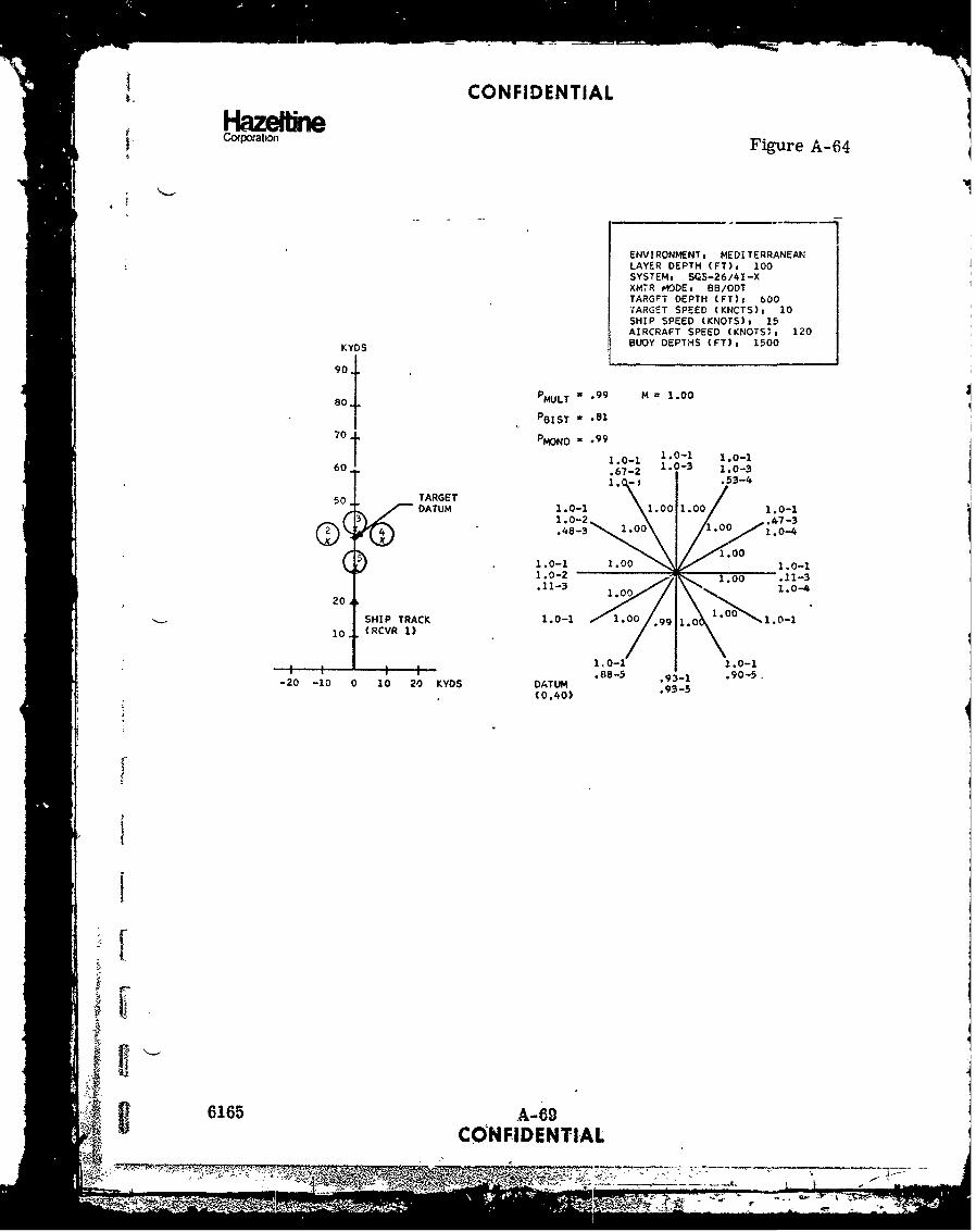
CONFIDENTIAL
i Coqxoat•oi Figure A-64
ENVIRONMENT# MEDITERRANEAN
LAYER DEPTH (FT)s 100SYSTEM, SQS-26/41-XXMTR lODE, BB/ODTTARGFT DEPTH (FT)t 600TARGET SPEED (KNCTS): 10SHIP SPEED (KNOTS), 15AIRCRAFT SPEED (KNOTS): 120
KYDS BUOY DEPTHS (FT) 8 1500
90
8 MULT = .99 M = 1.0080.
PBIST - .8170 PMONO - .99
60 .67-2 1.0-3 1.0-3
60 1.0- 1 .- .53-4
50 TARGETDATUM 1.0-1 .00 1o0 1.0-1
3 .0-2Z" .4-4 *.- 1.00 1.00
1.0-2
.11-3 1il0• 1.°0--4
20A10
SHIP TRACK 1.0-1 .0 .99\01. 0 1.0-110 (RCVR 1)
t = ' .88-5 .9i-1 .90-5 .-20 -10 0 10 20 KYDS DATUM .93-5 905"(0,40)
6165 A-69CONFIDENTIAL
.7-1 7<

HazeCON FIDENTIAL
Crpaton Figure A-65
ENVIRONMENT. MEDITERRANEAN
LAYER DEPTH (FT)o 100SYSTEM, SJ~S-26/41-XXM7R MODEs P13/GOT (2ND CZ)
TARGET DEPTH (PT): 300
TARGET SPEED (KNOTS): 10
SHIP SPEED (KNOTS): 15
AIRCRAFT SPEED (KNOTS)s 1.20
KYDS UOY DEPTHS (PT): '0
90. TARGET
DATUM PMULT = .76 M .77
I~~ ~ x=BST .62
@70 K X M0N0 = .600
R9 8.98-4 0 .01 *51-5.0-
50 51 43-6
40..0 .48
1.0-1 1.0-1.00 1.0________
30 1.00.1.0-
SHIP TRACK 1.0
20- (RCVR 1) 1 - .1.00 1.0 1.0-1
I 0.;6-2 1.00 1.0
11.0-1 1.0-1
.80-8 .91 1.0-8
-20 -10 0 10 20 ;.YOS DATUM 1.0-9 108 .80-9(0,70) 1.0-9
6165 Ar7OCONFIDENTIAL

CONFIDENTIAL
Corpoation Figure A-66
ENVIRONMENT s MEDITERRANEANLAYER DEP7H (FT)s 100SYSTEM3 SQS-26/41-XXMTR MODEs B/ODT (2ND CZ)
TARGEr D:PTH (FT), 300TAP2'.ET SPEED (KNOTS): 10Sh(P SPEED (KNOTS), 15AIRCRAFT SPEED (KNOTS)# 120
KYDS BUCY DEPTHS (FT), 1500
90TARGETDATUM PMULT = .77 M = .79
(D3V@ PBIST =77
S4 PMONO = .60 .23-353-4
.53-5C •.26-2 .17-6
c ®'.7• -319-4
50.o9-:, \.4 36 19 .09-1
40 :0.58-?
1 1.00 1.0-130 1.0--2
.28-3 -1.0-7
1.0-1SHIP TRACK 1.0-2 1.00 .-010 (RCVR 1) .98-3 oo0 1.0 1.0-81. 0-9 1.00-1 \ 1. 0- 1
1.O01-. .99-7! ): ;1.00-8 1.0-8
-20 -10 0 10 20 KYDS 1009 .99-1 1.0-9DATUM .10-2
1.0-8(0,70) 1.0-9
-i [
6165 A-71,-CONFIDENTIAL
7,777VmLTL 7-77

CONFIDENTIAL
Hazetbnerpor Figure A-67
ENVIRONMENT: MED!TERRANEAN( DAY)LAYER DEUPTH (FT): 100SYSTEM: S,.S-26/41-XXN4TR tMODE BDR/ODT
TARCET DEPTH (FT)s 300
TARGET SDEEO (KNOTS): 10SIiP SPEED (KNOTS): 15AIRCRArT SPEED (KNOTS)a 120
KYDS BUOY DEPTHS (FT): 60
90
80 PMULT = 1.00 M - 1.00
PBIST = -81
70 PMONO = 1.001. 11.0-1 .11-2 1.0-1
60 1.0-2 1.0-3 1.0-31.0-3 .99-4
50 TARGET 1.0-1 1.0-1
DATUM 1.0-2 .0 1.1.0-3O .- 3 10 .01.0-4© .oo• 1.00 •
1.01 110.00 10200 1.-0
.49-3 --. 43-3
SHIP TRACK1.00 0
(RCVR 1) 1.0-1 1.00 1.0 1.01O-
1.0-1 1.0-1S.....{ :: : --. 91-5 .92-5
-20 -10 0 10 20 KYDS 1.0-1DATUM .91-5(0,40)
fi
A-ý72_______CQNR I ENTIAL -
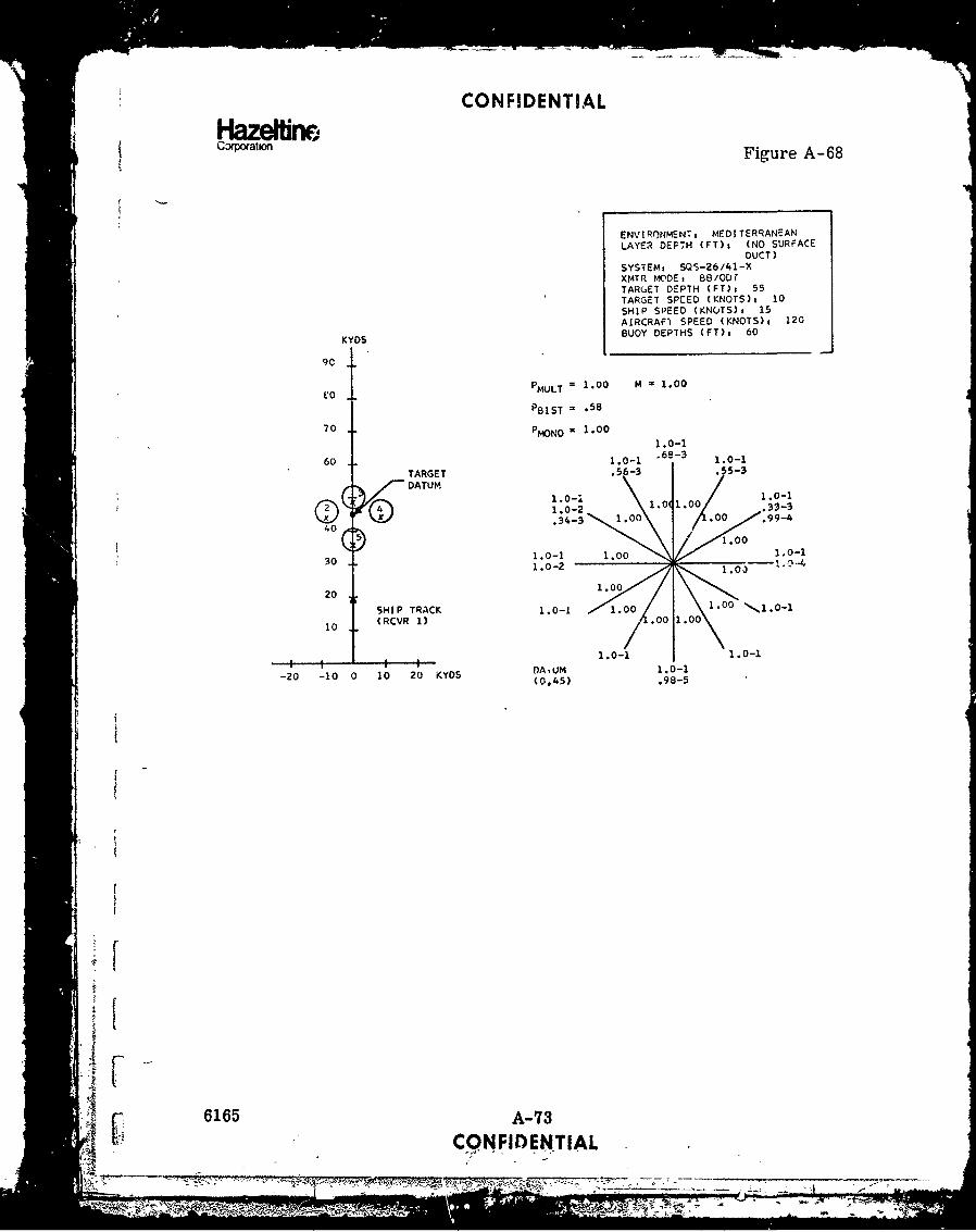
CONFIDENTIAL
HazeffineSCopoeaton Figure A-68
ENVIRONMENT MEDI TERRANEANLAYER DEPTH (FT)s (NO SURFACE
DUCT)SYSTEM. SQ$-26/41-%XMTR MODE: BB/ODfTAR(.ET DEPTH (FT), 55TARGET SPIED (KNOTS): 10SHIP SPEED (KNOTS), 15AIRCRAF1 SPEED (KNOTS), 120
KYDS BUOY DEPTHS (FT), 60
9C
.o PMULT = 1.00 M = 1.00
PBIST = .58
70 PMONO 1 .00
1.0-1
60 1.0-1 ' 6-3 1.0-1
TARGET .56-3 / 5-3
DATUM1.0-i 1.0.000-2/ .35-3
31- 1.00 / 1.00 1.0-1
1.0-2 .0 .0-4
1.00
20 1.00SHIP TRACK 1.0-1 1.00 1.00
10 (RCVR 1) .00 1.oo
1.0-1 1 1.0-1
-20 -10 0 10 20 KYOS DA.UM 1.0-1(0,45) .98-5
6165 A-73CONFIDENTIAL

CONFIDENTIAL
HazemneCorporation Figure A.-69
ENVIRONMEN`T: MEDITERRANEANLAYER DEPTH (FT), ('ýG SURFUCE
CuCT)SYSTEM, SQS-26/41-XXMTR MODE: ee /ODTTARGET DE PTH (FT): 55TAR16ET SPEED (KNOTS)t 10
SH!P SPEED (KNOTS): 15AIRCRAFT SPZED (KNOTS)s 120
KYD. BUOY DEPTHS (FT)s 1500
90
80 PMULT = 1.00 M = 1.00
PBIST = .46
70 P MONO = 1.00101 1.0-1.0-1
60 1.0-1 A-3 1.0-1
TARGEr .5 . 57-.3-DATUM /
1.0-2 1.0 1.00 .19-30"- 10 1.00 1.0-4
-.22-3 , .0o,,c o,
1 .00
1.0-1 1.00 1.0-1.32-2 1.00 .30-4
20 SHIP TRACK
(RCVR 1) .1.00
10 1.0-1 - . 1.0 1.0-1
1.0-1V.14-S .17-5
-20 -10 0 10 20 KYDS DATUM 1.0-1
(0,45) .52-5
6165 A-744 - COWHDENTIAL
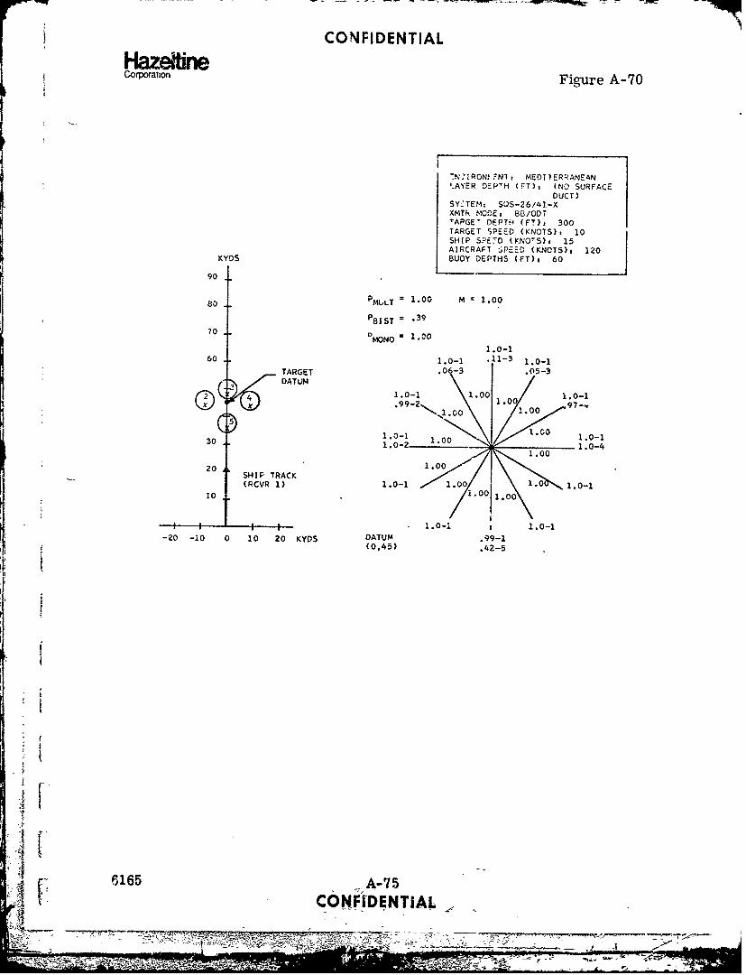
CONFIDENTIALHlazeftineCorporation Figure A-70
-N'IRONt 'NI, MEDIIERRANEAN'.AYER DEP'H (FT)t (NO SURFACE
DUCT)SY.-TEM: SQS-26/41-XXMTk MODE2 B5/ODTTAPGE" DEPTH (FT)S 300
TARGET SPEED (KNOTS): 10SHIP SPE.D (KNO'S), 15AIRCRAFT SPEED (KNOTS)s 120
KYDS BUOY DEPTHS (FT)3 60
90
so PMULT = 1.0o M z 1.00
POIST = *39
70 PMONO = 1.00
1.0-160 1.0-1 .11-3 1.0-1
TARGET .06-3 .05-3DATUM
41.0-1 1.00 1.010-1
-1 .00 1.00
30 1.0-1 1.0-1.0-,,, 1..oo
20 1.0020 SHIP TRACK 10
(RCVR 1) 1.0-1 1.00 $ 1.0 1.0-110 1.00 1.00
" I I I1.0-i 1.0-1
-20 -i0 0 10 20 KYDS DATUM .99-1(0,45) .42-5
I
I
" 6165 A-: F. CONF[DENTIAL
$.~OR

CONFIDENTIAL
HazeltineCorporation Figure A-71
ENVIRONMENTi PIEDITERRANANI YYER DEPTH (FT)s (NO SURFACE
DUCT)SYSTEMA: SU5-e6/41-xXrATP NICDE : ý - 'C'DT
TAR,,ET Dc..PTH WtF: 1 300TARET SPEED (KNOTS), 10SHIP SPEED (KNOTS)i 15AIRCRAFT SPEED (KNOTS), 120
KYDS BUOY DEPTHS (FT), 1500
90
8O PMULT = 1.00 M = 1.00
PBIST = .93
70 PMONO = 100 1.0-11.0-1 1.0-2 1.0-11.0-2 1.0-3 1.0-2
60 1.0-3 1.0-4 1.0-3
TARCET .98-4 1.0-4
DATUM 1.0-1 1.0-1.78-2
1.0-2 1.0 1.0 1.0-31.00
1.0-1 1.00 1.0-1.93-2 1.00 .05-2
.31-5 1.00 2 32-5
20 1.00
SHIP TRACK 1.0-1 1.0-1.;8-2 1. 00 1.00 .07-4
10 (RCVR 1) .99-5 .00 1.0 .99-5
1.0-1 1.0-1.34-2 .99-1 .07-3
-20 -10 0 10 20 KYODS .07-3 .18-2 .32-4
DATJM 1.0-5 .15-3(0,45) .17-4
.51-5
A 6165 A-76
CONFIDENTIAL
fUv.p 3-- -X

CONFIDENTIALH-IzeltineCop!ation
Figure A-72
ENVIRONMENT, MEDITEPRANEANLAYER DEPTH (FT), (NO SURFACE
DUCT)SYSTEM2 SOS-26/41-XXMTR MODE. BB/ODTTARGET DEPTH (FT)s 600TARCET SPEED (KNOTS)a 10SHIP SPEED (KNOTS)v 15AIRCRAFT SPEED (KNOTS), 120KYDS BUOY DEPTHS (FT)t 60
90
80 PMULT 1 .00 M = 1.00
PBIST = .43
710 PMONO = ".O0
1.0-260 1.0-1 .78-3 1.0-1
TARGET .07-2 .07-3
ýDATUM4 1.0-1 1.00 1. 1.0-1
1.- 1.00 01.0 0 1.0-4
) .1.0030 1.0-1 1.o0 1.0-11.00
20 4100
SHIP TRACK 0.0 1 0.00(RCVR 1) 1.0-1 1 01.0-00100.
S; ' I I1 .0 - 1 i1 .0 - 1-20 -10 0 10 20 KYDS DATUM 1.0-1
(0,45) .23-5
It
"6165 A--77
Q.... . ... ,A L
--S. . "-l

CONFIDENTIAL
HazeiineCorporation
Figure A-73
ENVI RONFrENT MED! T E R -fNEA7.NLAYER DEPTH (FT)i (NO WURFACE
£UCTISYSTEM, SUS-26/41-1XMTR MCDE, 8/ODT
TARGET D-PTHi (FT)i 600TARCýT 3PCED (KNOTS), 10SHIP SPEZ; (KNOTS), 15AIRCRAFT SPEED (YNOTS), 120
KYOS BUOY DEPTHS (FT): 1500
80 P MULT = 1.00 M = 1.00
PBIST = .971.0-1
70 PMONO = 1.00 1.0-21.0-1 1.0-11.0-2 1.0- .91-2
60 1.0-3 - 1.0-3
TARGET .55-4 1 0-4
DATUM 1.0-11.0-1 .50-21.0-2 1.0 1.0 1.0-3
x 1.0-4
C1.0-1 .00 1.0-1300, O0- .99-2.09-- z .09-3.23-;9-3 1.00 .82-4.23-5
20 1.00
cHIP TRACK 1.0-1 1.00 1.00 1.0-1
10 (RCVR 1) .98-5 i.0C 1. .98-5
1.0-1/ 1.0-1; • J,.15-2 .14-4
1.0-5 1.0-1 1.0-5-20 -10 0 10 20 KYDS DATUM 13-2
(0,45) .05-3
.13-4
.68-5
II
Ii
6165 A-78
- ,.CONFIDENTIAL
- i l I l

CONFIDENTIALHazeflrneCorporation Figure A-74
ENVIRONMENTg NORTH ATLANTICLAYER DEPTH (FT), 150SYSTEM: CASSXMTR MODE, 66/ODTTARGET DEPTH (FT)3 55TARGET SPEED (KNOTS): 10
90
3 TARGET M=.59if) DATUM
40
95-29
301.0-2 9 .17 31-
20 - 1.00 C
1130101 .0616 .17-4:ii___ __0__ 1.00IDNTA
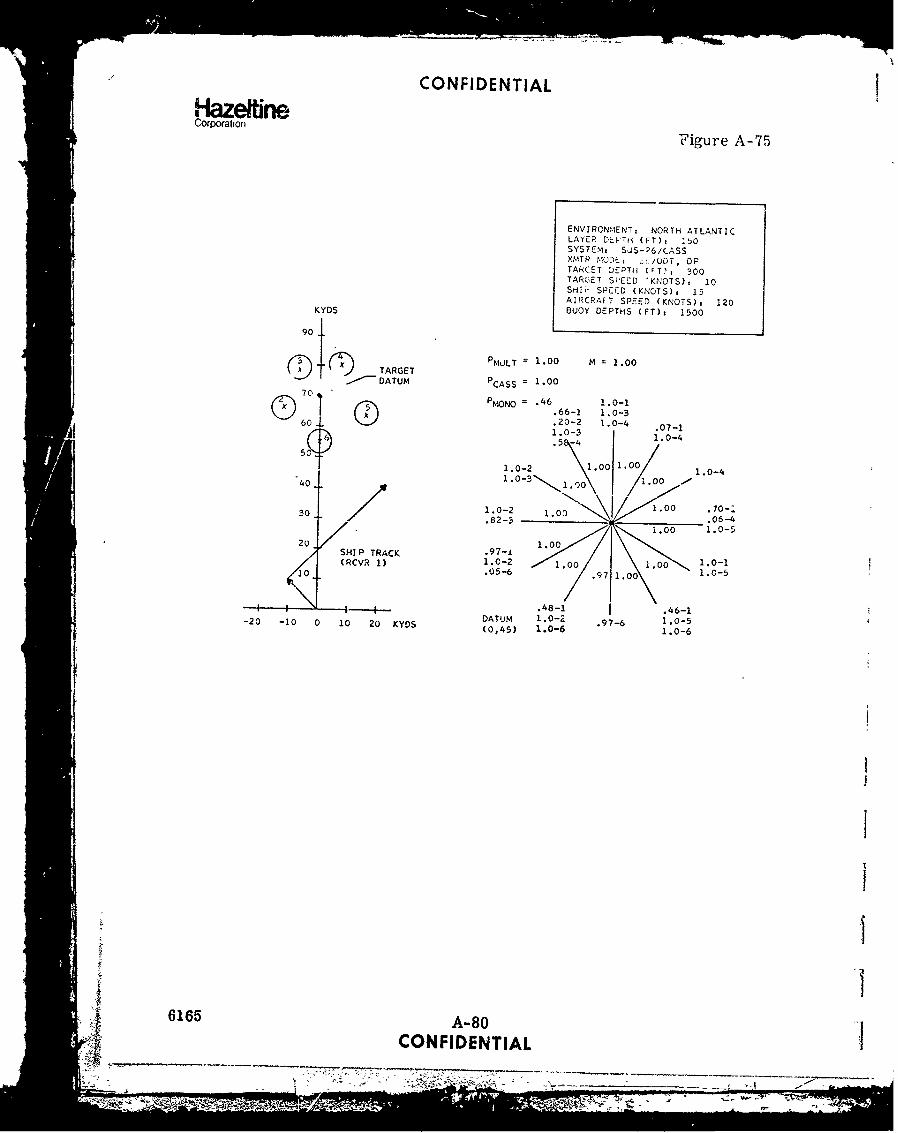
CONFIDENTIAL
Hazeline.Corporation Figure A-75
ENVIRONtIENT, NORTH ATLANTICLAYER DEPTH (FT), :'OSYSTEM, SjS-26/(ASSXMTP MODE, .zL/ODT, DPTARCET DEPTH (.T,: 300TARGET SPEVD "KNOTS), 10SHIU SPCCD (KNOTS), 15AIRCRAFT SPEED (KNOTS)t 120
KYDS BUOY DEPTHS (FT)s 1500
90
/3 TA PMJLT 1.00 M = 1.00
ý-L 0 TARGET P 10.- DATUM PCASS 1.0
70 No .46 .1.0-1.66-1 1.0-360 - .20-2 1.0-4 .07-1
1.0-3 1.0-4.5 \-4
1.0-2 .00 1, 1.0-4"40 / 1.0-3 1,0)0 1.00
30 1.0-2 1.O 1.00 .70-:
i.00 1.0-520. SHIP TRACK .97-i
(RCVR 1) 1.0-2 1.00 1.00 1.0-110 .05-6 .97 1.00 1.0-5
.48-1 4 .46-1DATUM 1.0-2 .97-6 1.0-5-20 -10 0 10 20 KYDS (0,45) 1.0-6 1.0-6
1.0-6
I
I1- ii
tI
6165 A-80CONFIDENTIAL
7777777777- ''I
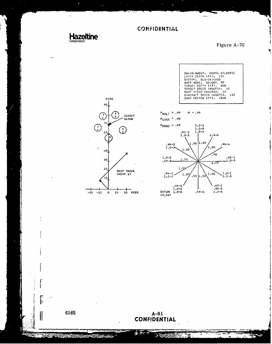
CONFIDENTIALHlazeffreC orpo ration F igu re A -76
ENVIR(NMENT, NORTH ATLANTICLAYER CýPTH (FT), 150SYSTEM, SUS-26/CASSXMTR MODE, 83/ODT, DPTARGET DEPTH (FT', 600TARGET SPEED (KNOTS)s 10SHIP SPEED (KNOTS), 15AIRCRAFT SPEED (KNOTS), 120
KYDS BUOY DEPTHS (FT). 1500
90
S(4 TARGET PMULT = *99 M = .99
uxDATUM PCASS = -99
70 PMONO = .42 1.0-1
60 .61-1 0-4• .1 I0-3 1.0-4
.99-2 1.0 .00 .96-4
4.4-1 " 1.00 .96 0-
1~ ~ ~ 0o21,-
,Z1.0-2. 1.01 .- 5
-20 -10 0 10 20 KYDS DATUM 1.0-6 .99-6 1,0-6(0,45)
SI
Sm6165 A-81
S ,- -CONFIDENTIAL ~ i7IL . 7

Hlzeline UNCLASSIFIEDCorporation
APPENDIX B (U)
SURFACE SCATTERING: INFLUENCE ONACOUSTIC PROPAGATION LOSSES
A. INTRODUCTION
(U) The calculation of acoustic propagation losses in the ocean using raytracing computer models leads to two surface related problems: 1) noenergy is predicted in the shadow zone where ray paths do not exist;2) a reasonable choice must be madc for surface losses due to reflectionin the specular direction.
(U) Energy in the shadow zone can be calculated from equations based onempirical data such as measured in the AMOS sea experiments. Thesedata, however, are restricted in their applicability and therefore can-not be generalized for all environments and sonar (or target) depths.
(U) Empirical surface reflection data is not always available for environmentsand sea conditions of interest.
(U) The present discussion shows how a unified theory of surface phenomenaincluding effects of scattering, bubble effects, and diffraction leads tomore general and widely applicable solutions to these problems.
B. SCATTERING FROM A ROUGH SURFACE
(U) Our point of departure for developing a general function for surface scat-tering is the equation for scattering from a gaussian distributed roughsurface as derived by Beckmann. The general scattering equation canbe written as:
-9 O2 7 T2F2sin2 61 g1.I gvxy 2 2 /4m)Ss e-g + 2 mr e (1
X m=l
where:
S1+ sin e sin 0G- cosO cos e Cos 0iF 1- 2 (2)sin 1 + sin 0 sine(
1 1 2
" F 24 (co 2 e126vy Y 1 Cse-2 co, e cos eCos0+ Cos ) (3)
46165 B- IUNCLASSIFIED

-zeltfitv UNCLASSIFIEDCorporation
2-- 2 (sin 61 + sine2 2 (4)
>2)
and 1 and 1)2 are the incident and reflected grazing angles at the scat-terer, 1 is thie azimuthal angle at the scatterer, T is the surface correlationlength, Y is the rms wave height and X is the acoustic wavelength. g isthe acoustical roughness of the surface and depends on the scatteringangles as well as on wave height. p is a function which is 1 in thespecular direction (01 = - 2' 0 = 0) aRd 0 elsewhere.
(U) At this point, most authors restrict the value of g in order to useasymptotic expressions tor equation (1). This, however, also restrictsthe generality of their solutions and, in many cases, asymptotic expres-sions are used outside their range of applicability.
(U) Since we are interested in scattering at all- angles and for varying surfaceroughness, we will use equation (1) for our scattering function. We willutilize asymptotic expression found from (1), however, the values of gat which these expressions will be used are kept well within the limitsof good approximations and cover all possible values of g. The threeregions of g, which we consider and the expressions used are:
2F 2 sin 21 .-v Ti24m)/g4m=e =_ eexy_.g__ (5)SsX2 ' _ • (5
20 22
2 2 ~ 2 2 2 em Xv T /4m\S5 = Po2 + T2F sin 6 gm C -Vxy 14) l<g10 (6)Ss e 2 Z m:m"
2 222 22TF2 T2 sin2 01 -v T 24 G
S 1e z t>1y (7)s 2 2 2
where:
2 4w 42 2V 2 ! (sine4 + sine2) (8)
v|
(U) The validity of these expressions when used in the regions of acousticalroughness as indicated is well illustrated in Figure 1 of a paper byMedwin. 2
6165 B-2]UNCL'ASSIFIED
, , , i I I I I I nI I II-

Hazefne UNCLASSIFIEDCorwoaton
(U) In using these equations for calculating surface scattering coriect valuesfor the surface correlation length I, and the rms wave height a must befound as a function of -wind velocity. Following the approach used byMedwin3 which assumes an isotropic gaussian distributed rough surf..ce,we have a relation between T, a , and the mean square surfa-e s!ope Z:
-9T 2c- (9)
Z is f und from the generally accepted expression derived by Cox and
Munk ;
r' = 5.12 x 10⁻⁵ W + ).003 (10)
where W is the wind velocity in cm/sec.
(U) The choice of the correct value for a depends on the factor of sea surfaceroughness which contributes most strongly to surface scattering. Whilemost authors choose a formula for the wave heights of a fully developedsea, we have used values of rms wave height as found emigrically in astudy of reverberation backscattering by Garrison et. al.. The 1 :'"-- Sof a found in their study range from about 1 to 7 inches for wind velocitiesfrom 6 to 17 knots. These values are considerably smaller than waveheights from a fully developed sea and indicate that the major contributionof scattering arises from small perturbations of the developed sea. Itis probable that contributions from both effects, the developed sea wavesand local facets should be included, but the second term seems to be
i "dominant Ln scattering and leads to more reasonable values of specularsurface reflection coefficients.
C. REFLECTION COEFFICIENT
1. Surface Scattering Effects
(U) The reflection coefficient for the surface cannot be assumed to consistof simply the specuilar term of equation (1) because for actual processors,energy arriving during a finite time period (10 ms in our study) isdetected and therefore all energy arriving during this time must beaccounted for in calculations. This means that the reflection in thespecular direction will consist of the actual specular term from (1) plusall scattered energy arriving within 10 ms of this specular ray.
(U) A computer program was written which calculates reflection coefficientby integrating the energy scattered into the specular direction. This
4 f ~program is adaptive in both time and space; that is, it integrates energy
6165 B-3
U N CLASCSIFIED'- _7J

HzfieUNCLASSIFIEDCorporation
arriving from points around ever increasing sized circles centered"•round the specular contact until either: 1) the contribution becomesnegligibly small or 2) the ray travel time is outside the bounds of theprocessor integration period.
(U) Our approach to surface reflection also eliminates the problems whicharise when trying to use closed form solutions for the reflectioncoefficient. If rlosed forms are used, the assumption must be madethat the source and receiver are in the far field (Fraunhofer region).Tests of these types of solutions indicate that predicted losses are5-20 dB too high and this is because all of the arriving energy is notaccounted for.
(U) The adaptive integration utilizing the whole scattering function is equiva-lent to a Fresnel solution which has been deemed necessary by severalauthors.
(U) Because we have preserved the form of the scattering equations usefulfor all values of g, reflection coefficients can be calculated for all inci-dent angles from 0 to 90 0 The results for various wind velocities areshown in Figure 1. The negative surface losses found for smallgrazing angles are actually gains and this is reasonable both from amathematical point of view and from similar experiments in optics.The fact that this is never seen in sea experiments is due to bubblelosses which are always present in a rough sea. (If the sea surface weresmooth, then there would be no bubbles but also. no scattered energy andR would be 1.)
2. Bubble Effects
(U) Air bubbles near the sea surface have a two-fold effect on surface reflec-tions: 1) absorption and scattering of energy from an acoustic ray and2) refraction o.' the ray changing its angle of contact with the surface.This topic is discussed in detail in Medwin's paper 3 and the mathematicswill not be presented here. The final results can be summarized here inthe following equations.
(U) The surface loss in dB per bounce due to bubbles is given by:
0Ab= 2jab dS (11
ab= 3 . 2 7 x 10- 5fo W(+ 10- W) (1+0.1Z)" (12)
b 0
6165 B-4UNCLAS'SIFIED
LL
~~~~~~~~ý ii I i I I II I I 1 I 1

Sae UNCLASSIFIEDCoiporationa
Figure I
4N4
- I
i-.
6165 B-5UNCLASSIFIED.
•.•++ • +-+ • , •+++=- ....... +- • • .I I II I I I Ii n 7

Hazeffine UNCLASSIFIEDCorporation
Z is the depth, W is the wind velocity in knots and f is the resonentfrequency cf the bubbles. The integration extends aong the acoustic raythroughout the layer L where bubbles exist. This exprnssion can benumerically iategrated tby using short straight line segments along thepath.
(U) The angle of incidence at the surface can be computed fxomn the n•-bubble incident angle by using the equations:
Cs = C(1-f) (13)
Fc= 9.74x 10-h5 W(l 10- 4 W2) (14)
where C is the uncorrected acoustic velocity at the surface and W iswind velocity in knots. The incident angle is then found from Snells' law;
cos O cos 0
C CS 0
where C0 and 90 are values found at the bottom of the bubble layer.
(U) We have found it reasonable to use a value of fo - 10000 Hz which iszonsiderably lower than that proposed by Medwin. This can be explainedby the observation that bubbles tend to form in clusters and thus theaverage "bubble" size increases and the resonant frequency decreases.
(U) The bubble losses calculated using these values and a wind velocity of17 knots are shown as curve 2 in Figure 2. The lower scales representthe uncorrected and bubble refraction corrected ( ) grazing angles.The reason the curve has a peak is that rays with shallower angl i donot pass through the whole bubble layer.
(U) Also shown on this figure, is the loss due to surface roughness (curve 1)and finally the total surface loss per bounce for reflection in the specul ardirection (curve 3).
D. PROPAGATION IN THE SHADOW ZONE a
(U) Energy propagated into the shadow zone was calculated using a tchniquesimilar to that of Schweitzer . The basic geometry is illustrated i.n jFigure 3. The fundamental operation used to calculate the propagatvonloss from target to receiver is:
6165 B-6-UNCLASSIFIED
'4 ~ oo -WV M,01ý,---,- --

- UNCLASSIFIED
HazeltineCorporaon Figure 2
I ..13
N Ira
UI, N C I'SED
UNRS R7k
S....-- •>,.•.•! • •/
+ + +/

�: � *
H�IZe1tIne UNCLASSIFIEDCorporation Figu±e 3
K
I.I.
N
*1
-
C.. I..
*1I
6165 B-8UNCLASSIP�ED
* �>-t - r � -
- '*�;.� **-, **��4* "�''� � � � _____ -� -
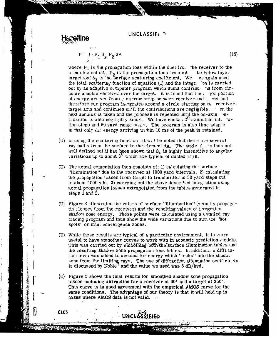
i n eUNCLASSIF.Corporatl,
P 1 Ss P2 dA (15)
where Pl is +he propagation loss within the duct fro. fhe receiver to the
area element tC , P 2 is the propagation loss from dA the below layertarget ard S3 is 'he surface scattering coefficient. We ve again usedthe total scafterirn6, function of equation (1) and the integi, on is carriedout by an ad.apti-ve cmputer program which sums contribu, vis from cir-cular annulae cent3re ' over the target. It is found that the "jor portionof energy arrives from ' narrow strip between receiver and t, -et andtherefore our program ir.,Lgrates around a circle starting on tl, receiver-target axis and continues un•il the contributions are negligible, en thenext annulus is taken and the -rocess is repeated untl the on-axis 'n-tribution is also negligibly small. We have chosen 2 azimuthal intl -a-tion steps and 50 yard range stvij s. The program is also time adapti\irn that on- L:.nk- energy arriving w,-hin 10 ms of the peak is retained.
(U) In using the scattering function, it wi I be noted lhat there are severalray paths from the surface to the element dA. The angle 0,, is thus notwell defined but it has been shown that S, is highly insensitive to angularvariations up to about 3 which are typicai of ducted rmys.
S(U) The actual computation then consists of: 1) calculating the surface
"iliumination" due to the receiver at 1000 yard intervals. 2) calculating
the propagation losses from target to transmitte,' in 50 yard steps outto about 4000 yds, 3) carrying out the above descr.bed integration usingactual propagation losses extrapolated from the tabls generated insteps 1 and 2.
(U) Figure 4 illustrates the values of surface "illumination" (actually propaga-tion losses from the receiver) and the resulting values of i'tegratedshadow zone energy. These points were calculated using a (.9tailed raytracing program and thus show the wide variations due to sunt wce "hotspots" or mini convergence zones.
(U) While these results are typical of a particular environment, it is -lore
useful to have smoother curves to work with in acoustic prediction lodels.This was carried out by hfidothing -bo-ththe'surface'illumination tables andthe resulting shadow zone propagation loss tables. In addition, a diff ac-tion term was added to acf:ount for energy which "leaks" into the shado\,zone from the limiting, rays. The use of diffraction attenuation coefficie,'ts{ is discussed by Noble' and the value we used was 6 dB/kyd.
(U) Figure 5 shows the final results for smoothed shadow zone propagationlosses including diffraction for a receiver at 60? and a target at 250'.This curve is in good agreement with the empirical AMOS curve for thesame conditions. The advantage of our theory is that it will hold up in
cases where AMOS data is-not valid.
6165 B-9"- ~~U NCLASS:IElED ,ýX A l fl -D
,~ - - 4':. ~- 71
UNCLASSIFIED
C o r m t i o nF i g u r e 4
Pc 0
K 0
a P. 0oPc
Ux
x 0k
0c
TI-5-0

UNCLASSIFIED
co~rtionFigure 5
X/
•,
/S~/
t4 D / ×1
X j
Ix
J/
6 6 B -11
, /K I
, U 4/ D
/ 4
i (l~p• s•'v,;, ,•/ev•ood
i/",•:: r- 6 65 B- 1
Z3
Hazeffne* UNCLASSIFIEDCorporation
(U) Reversing the roles'of receiVeer-and target from those shown in Figure 3will lead to entirely different results if the receiver is directional slacemost of the energy comes down from the surface at rather steep angles.This fact is iwpoztant in the placement of vertically directional sono-buoys in environments whbfie~sIhkd6w zones exist.
(U) Another point of interest is the fact that if much of the energy arrivingat a target in a shadow zone comes from above , then corrections shouldbe made to the concept of target strength in these situations.
E. CONCLUSIONS
(U) A unified technique of applying scattering theory to shadow zone propaga-tion and surface reflection has given results which agree with measureddata but are much more widely applicable. The results are encouragingenough to merit further study, particularly in terms of experiments tomeasure the time spreading of surface retlections, the actual reflectioncoefficients calculated and the influence of the theory on target strength.
I
I
I
I
I
6165 -B12
UNCLAS-SIFI-
Kk.LW =M '07114M.

Hazeýrine UNCLASSIFIEDCorporation
REFERENCES (U)
1 . P. Beckmann and A. Spizzichino, "The Scattering of ElectromagneticWaves from Rough Surfaces," MacMillan Company, New York (1963).
2. H. Medwin, "Specular Scattering of Underwater Sound from a WindDriven Surface," Journal of the Acoustical Society of America, Vol. 41,No. 6, (1967).
3. H. Medwin, "The Rough Surface and Bubble Effect on Sound Propagationin a Surface Duct," 28th Navy Symposium on Underwater Acoustics,November 17-18, 1970.
4. C. Cox and W. Munk, "Measurement of the Roughness of the Sea Surfacefrom Photographs of the Sun's Glitter," J. Opt. Soc. Am., 44, 838-850,(1954).
5. G.R. Garrison, S.R. Murphy and D.S. Potter, "'Measurements of theBackscattering of Underwater Sound from the a Surface," J. of theAcoust. Soc. of Am., Vol 32, No. 1, (1950).
6. B.J. Schweitzer, "Sound Scattering into the Shadow Zone below anIsomthermal Layer," J. of the Acoust. Soc. of Am., Vol. 44, No. 2,11968).
7. W.J. Noble, "Theory of the Shadow Zone Diffraction of UnderwaterSound," J. of the Acoust. Soc. of Am., Vol. 28, No. 6, (1956).
tI
f
r
616,1 B-13ý,c IJNCLAS S9FIED____
-
w . .'

lazeitmn UNCLASSIFIEDCorpmtatn
Appendix C (C)
DISTRIBUTION LIST
6165 C-1
MNCL-ASSIFIED

Hazeltine UNCLASSIFIEDCorporation
DISTRIBUTION LIST FOR"OPERATIONS ANALYSIS OF A MULTISTATIC ECHO RANGING SYSTEM"
No. of Copies
Director 1Defense Research and EngineeringDepartment of DefenseWashington, D. C. 20301
Assistant Secretary of Deferse(Systems Analysis)
Department of DefenseWashington, D. C. 20350
Joint Chiefs of StaffStudies, Analyses, and Gaming AgencyWashington, D. C. 20301
Assistant Secretary of the Navy(Research & Development)
Department of the NavyWashington, D. C. 20350
Chief of Naval ResearchDepartment of the NavyArlington, Virginia 22217
(Code 461) 1(Code 462) 2(Code 466) 1
Chief of Naval OperationsDepartment of the NavyWashington, D.C. 20350
(Op-02) 1(Op-03) 1(Op-32) 1(Op-05) "(Op-9 5 ) 1(Op-952C) 1(Op-96) 1
6165 C-2 I... I I UNCLA Ei•Pi l

HeUNCLASSIFIEDCorporation
No. of Copies
Chief of Naval MaterialWashington, D. C. 20360
(Code ASW-141) 1(Code ASW-142) 1(Code ASW-22) 1(Code NAIR-5031C) 1(Code NAIR-APC256A) 1(Code PM-15) 1(Code PMS-380) 1(Code EP-03) 1
COMASWFORLANT
Norfolk, Virginia 23511COMASWFORPAC 1FPO San Francisco 96601COMASWFORSIXTHFLTFPO New York 09521COMSUBDEVGRU 2USN Submarine BaseNew London, Connecticut 06320
COMCRUDESLANT 1
U.S. Naval BaseNewport, Rhode Island 02840
COMCRUDESPAC 1FPO San, Diego, California 92132DESDEVGRU
2U.S. Naval BaseNewport, Rhode Island 02840
(Mr. R. Johnson) 1(Library) 1
COMFIRSTFLT
FPO San Francisco 96601Commanding OfficerUSS GLOVER (AGDE-1)FPO New "fork, New York 09501
Naval AcademyAnnapolis, Maryland 21402
(ATTN: Librarian)
Naval Postgraduate SchoolMonterey, California 93940
(ATTN: Librarian) 1
6165 C-3UNiCLASSII II

. . . . . . ' , -,,, ,, . . . . .
Hazefim UNCLASSIFIEDCorporation
No. of Copies
Naval War CollegeNewport, Rlhode Island 02840
(Lib r'ary) 2
Naval Research LaboratoryWashington, D. C. 20390
(Code 7805) 1(Code 2620) 2
Naval Air Development CenterJohnsville, Pennsylvania 18974
(AETD) 1(SDD) 1(Library) 1
Naval Electronic Laboratory CenterSan Diego, California 92152
(Code 230) 1(Library) 1
Naval Ship Research & Development CenterBethesda, Marylan-) 20034
Naval Undersea Research & Development CenterSan Diego, California 92152
(Dr. J. Stewart) 1(Dr. G. Kinneson) 1(Library) 1
Naval Underwater Systems CenterNew London LaboratoryNew London, Connecticut 06320
(Code 2130) 1(Mr. J. Hanrahan) 1
Naval Underwater Systems CenterNewport LaboratoryNewport, Rhode Island 02840
Naval Weapons CenterChina Lake, California 93555
(Code 12) 1(Library)
Naval Coastal S'-rtems Laboratory 1Panama City, Florida 324029
Naval Ordnance Laboratory 1White OakSilver Spring, Maryland 20910
6165 Oz,4'UNCLSI "--, .
S_ _ _ _ _ _ _ _ _ _ _ _ _ _ _ -N'--

UNCLASSIFIEDC.Or:xrtion No. of Copies
Naval Weapons LaboratoryDahlgren, Virginia 22448
(ATTN: Library) 1
Applied Physics Laboratory 1John Hopkins University8621 Georgia AvenueSilver Spring, Maryland 20904
Ketron, Incorporated656 East Swedesford RoadWayne, Pennsylvania 19087
(Mr. J.D. Kettelie) 1
Arthur D. LittleAcord ParkCambridge, Massachusetts 02139
(Dr. J.N. Dobbie)
Mathematics, Inc.4905 DelRay AvenueBethesda, Maryland 20014
(Dr. Saul Gass)
Operations Research, Inc.1400 Spring StreetSilver Spring, Maryland 20910
(Dr. E. Holmboe)
Naval Warfare Research CenterMenlo Park, California 94025
(Mr. Larry Low)
Tetra-Tech, Inc.1911 Fort Myer DriveArlington, Virginia 22209
(Mr. Klinkner)
Vector Research, Inc.P.O. Box 1506Ann Arbor, Michigan 48106
(Dr. Seth B'nder) 1
Daniel H. Wagner Associates, Inc. 1Station Square OnePaoli, Pennsylvania 19301
Institute for Defense Analyses 1400 Army-Navy DriveArlington, Virginia 2-2202
Defense Documentation Center 2Cameron- StationAlexandria, Virgi'da 22314 - -
6165 C-5 4 (This page is _-
~ _ll l l l l l l l l l l l

Hazdbr*UNCLASSIFIEDCorporation No. of Copies
NAVSECHyattsville, MD 207821(Code 6112)(-\/r. Dave Mandel)
UNCIASSIFIED __
-j -t 71