Embed Size (px)
Citation preview
UNCLASSIFIED
AD NUMBER
LIMITATION CHANGESTO:
FROM:
AUTHORITY
THIS PAGE IS UNCLASSIFIED
AD859594
Approved for public release; distribution isunlimited.
Distribution authorized to U.S. Gov't. agenciesand their contractors; Critical Technology; MAR1969. Other requests shall be referred to AirForce Rome Air Development Center, EMATA,Griffiss AFB, NY 13440. This document containsexport-controlled technical data.
RADC, USAF ltr, 17 Sep 1971
WlM0
^
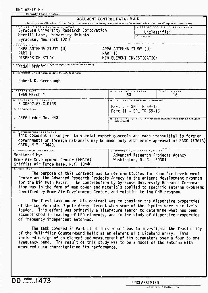
RADC-TR-69-191, Volume Final Technical Report 4 March 1969
O V") ARPA ANTENNA STUDY
)
PART I - DISPERSION STUDY
Robert K. Greenough
Contractor: Syracuse University Research Corp.
Contract Number: F30602-67-C-0138
Effective Date of Contract: 27 November W7 Contract Expiration Date: 27 October 1968
Amount of Contract: $50,000
Program Code Number: 7E30
Principal Investigator: Robert K. Gieenough
Phone: 315 477-7077
Project Engineer: C S. Malagisi
Phone: 315 330-2443
This document is subject to special export controls and each transmittal to foreign governments or foreign na- tionals may be made only with prior approval of RADC (EMATA), GAFB, N. Y. 13440.
Sponsored By
Advanced Research Projects Agency ARPA Order No. 943
Rome Air Development Center Air Force Systems Command
Griffiss Air Force Base, New York
rj-»-inru-irjirJWJ>rj r. «• - T. rjynirysv»:ü^rvTUxi_n ^j!_»_■!^ t. *»-. ■." w£sa m"-' -..rr»- a a sanaiBi ■; laa i naggna

When US Government drawings, specifications, or other data are used for any purpose other 'han a definitely related government procurement operation, the government thereby incurs no responsibility nor any obligation whatsoever; and the fact that the government may have formulated, furnished, or in any way supplied the said drawings, specifications, or other data is not to be regarded, by implication or otherwise;, a. in :>ny manner licensing the holder or any other person or corporation, or conveying any rights or permission to manu- facture, use, or sell any patented invention that may in any way be related thereto.
If this copy is not needed, return to RADC (EMATA), GAFD, N.Y. 13440.
^T*TJC7>^JOV(.?>o.-">THü-:r>:r> >>:'>■-> ?ic&; r ^ K«uöffiWi p>?j.>>.rJ.>^\>>-i- äESK ^^jc-^^J^r^^jr^y^-r^.^-A^ %& a m m wa, ^T .> ggaaMü
ARPA ANTENNA STUDY PART I - DISPERSION STUDY
Robert K. Greenough
Syracuse University Reseirch Corp.
This document is subject to special export controls and each transmittal to foreign governments or foreign na- tionals may be made only with prior approval of RADC (EMATA), GAFB, N. Y. 13440.
This research was supported by the Advanced Research Projects Agency of the Department of Defense and was monitored by C.S. Malagisi, RADC (EMATA), GAFB, N.Y. 13440 under contract F30602-67-C-0138.
SSSH?&S&5&MfiKS«^m^^

§8 FOREWORD
I N
This report covers the tasks performed under Contract F 30602-
■j 67-C-0138, Exhibit Line Item A010. The report is in twc parts, each rA covering a task related to the Big Push Radar Program. The tasks were
mj approved and monitored by the Rome Air Development Center. The
$. Project Engineer was Mr. Carmen Malagisi.
m f'..1 This technical report has been reviewed and is approved.
ä i
/-:•'
I
EMATA
i 11
i

i
i
i D
i i K
h
h
i
TA3LK OF CONTENTS
■ Section Page
I I. INTRODUCTION 1
II. DISPERSION STUDY 2
I . Foreshortened Dipole Array 2
£> 2. Dispersive Properties 6
3. Application of K-(3 Diagram to LPD Antenna 10
4. Conclusion 1 1
5. Recommendations 12
REFERENCES 13
in

LIST OF ILLUSTRATIONS
Figure Page
1 Types of Reactive Loading 3
2 Constant Width Log Periodic Dipole Antenna - Inductive Loading 5
3 Transient Response Spiral Antenna 8
4 Sketch Explaining the Mechanism of Delay Distortion 9
IV
'-jii'./rj'r*r.j.'j,rj'rjrj' rjrj<sj*j/\rs/s fs^s^s. s. <.'rer*'-.-<* •^.i.'^.*.- '-■'.■■*[?.'.•, ■.■::■>.; ■n,'-, ■ ■. w.»i*-i.-'.i »i «L.» ,*. ..^.-^ ,■»:■-,..,».. ^
ü
I of
g
I
(':•.
1 J
i
'.-■
■.-.
SECTION I
INTRODUCTION
The purpose of this contract was to perform studies for Rome
w Air Development Center and Advanced Research Projects Agency in
the antenna development program for the Big Push Radar The con-
&J tribution by Syracuse University Research Corporation was in the
form of man power and materials applied to specific antenna problemo
g>( specified by Rome Air Development Center, and relating to the OHR
Ks program.
The first task under this contract was to consider the dispersive
properties of the Log Periodic D pole Array element when some of the
*'.X dipoles were reactively loaded. This effort was primarily a literature
search to determine what has been accomplished in loading of LPD ele-
ments, and in the study of dispersive properties of freq\iericy independent
antennas.
^\^\v^yA\vv^A^^vw^v\MAA■^.l^v^^v,^Lvv■vl■^-n^^.v■^^■^^\^\-.v.•1,-.•,*.-, &3-^. -. -. v. m -.v-.- ".•, ^sa sa -.i -.•. -.' •.•. ■o ■'.aaaa ■■ v, aa iVf/, l-.rrls
i
S
c
1}
SECTION II
DISPERSION STUDY
The Log Periodic Dipole Array is a pseudo-frequency-independent
antenna, capable of operating over a wide frequency band with essentially
constant pattern and impedance characteristics. The application of the
LPD in a wideband array requires the consideration of the farfield phase
response with frequency as well at> the amplitude response. CarreT has
shown that the phase is proportional to the logarithm of frequency, making
it poasible to adjust the phase of an LP antenna independent of the pattern
and input impedance. This property has been and is being used in the (2)
design of arrays of LP antennas^ '.
The LPD antenna is currently being considered as the element for
the broadband array of the CONUS Antenna Modeling Study. The size of
the antenna and the required proximity of the elements of the array dictate
the need for foreshortening the dipoles at the low frequency end of some of
these elements. This can be accomplished by r?actively loading the longest
dipoles of the LPD element to obtain a shortening factor of approximately
two to one. The question has arisen as to the effect of this loading on the
frequency response or dispersive properties of the LPD antenna with fore-
shortened elements, compared to the unloaded LPD. The purpose of this
study was to determine the effects of loading on dispersion and to obtain
some insight into the dispersion properties of the class of antennas which
includes the LPD array.
1. FORESHORTENED DTPQT.F: ARRAY
A number uf papers have been published describing methods for the (34567^
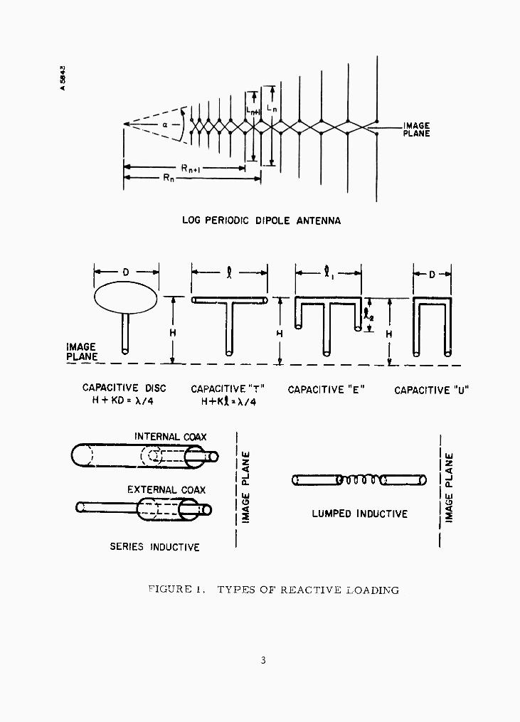
foreshortening of elements of an LPD antennav ' ' ' ' -. Figure 1 sh
(x) some of the methods of loading of individual dipole elements to achieve
UagiäSii2&&S£as2£&&&ffi^^
LOG PERIODIC DIPOLE ANTENNA
IMAGE PLANE
H
_L__ H "-^ H H
i
IMAGE PLANE
CAPACITIVE DISC CAPACITIVE "T" CAPACITIVE "E" CAPACITIVE "U" H + KD=X/4 H+KJl = X/4
a
INTERNAL COAX
G (-CTfr EXTERNAL COAX
^^D
SERIES INDUCTIVE
UJ z <
o 2
c Bmnnnrts ID
LUMPED INDUCTIVE
1
I -i a. UJ
FIGURE 1. TYPES OF REACTIVE LOADING
VS/WV-AV^ . JOm ^■\\S.V'.,>.\->rty .■■v.- -.X^'.-.^^K^A <\-^ o ■^-. .•'/v-^-V'.... -i ■--.-.^-cio^-i AKiSMSüaH^EäS '--<.
r
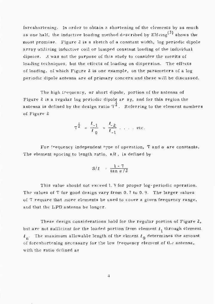
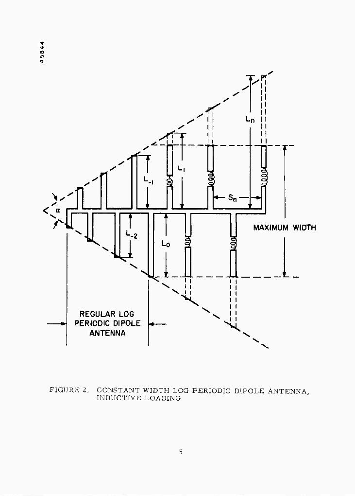
foreshortening. In order to obtain a shortening of the eLements by as much (3) tf as one half, the inductive loading method described by Elfving shows the
most promise. Figure 2 is a sketch of a constant width, log periodic dipol
ifc array utilizing inductive coil or lumped constant loading of the individual SO yji dipoies. it was not the purpose of th;s study to consider the merits of
S loading techniques, but the effects of loading on dispersion. The effects
^ of loading, of which Figure 2 is one example, on the parameters of a log
periodic dipole antenna are of primary concern and these will be discussed
I \fiji
1
i 5?
^
?
e
e
I 1 he high trequency, or short dipole, portion of the antenna of
S} Figure 2 is a regular log periodic dipole ar ay, and for this region the
antenna is defined by the design ratio T2 . Keferring to the element numbers
(TJ of Figure 2
^ ^ ^ 1 ^ 2 ^ = f1 =--■•■■ etc.
1 0 -1
For frequency independent type of operation, T and a are constants.
The element spacing to length ratio, s/l , is defined by
I s/, ^ tan a / Z
This value should not exceed 1. 3 for proper log-periodic operation.
The values of T for good design vary from 0. 7 to 0. 9- The larger values
of T require that more elements be used to cover a given frequency range,
and that the LPD antenna be longer.
These design considerations hold for the regular portion of Figure 2,
but are not sufficient for the loaded portion from element i1 through element
i . The maximum allowable length of the elment i „ determines the amount n 0 U
of foreshortening necessary for the low frequency element of the antenna,
with the ratio defined as
m^x^o-A^-^^wjo^*^^ ■> w^- ->•> rj- v»
CD
s
s < a
v. >\nr
T^n
■rT
^r ^.___
7 I
--2
U \
REGULAR LOG PERIODIC DIPOLE
ANTENNA
Lo
^^l1 ^^L' X
MAXIMUM WIDTH
\
X \
FIGURE 2. CONSTANT WIDTH LOG PERIODIC DJPOLE ANTENNA, INDUCTIVE LOADING
W//OVW.S^V.V/^-AV.VL^^ '/•-.-•■■•• ■■■ -•■.-- V' ism a v- >> ta^k -... ^ --■ > ■ •.> i -■> • > •.

i
F.S. = r-"- 1 0
00 The amoant of foreshortening increases for the lower frequency
dipoles, starting with dipole i~ for which little or no foreshortening is
Rl required. To maintain the same frequency independence in the loaded
portion as the unloaded, the current distribution in the elements around
a resonant element must be the same for the two regions. An increase
in the loading of an element causes the corresponding element Q to be
« increased. This higher Q and the increased characteristic impedance
of the elements do not allow efficient coupling between the elements in the
rj\ active region and the antenna transmission line.
m
'."■
These problems suggest a larger value of T in the loaded portion
of the LPD antenna. The increase of T dictates that the number of elements
needed to cover a given frequency range becomes larger. The increase
in the number of element.« also requires an increase in the boom length,
or overall antenna length.
Although the foregoing discussion was based on inductively loading
the elements, the same argument holds for all the types of loading referred
to in Figure I. When the design parameters in the loaded portion of the
LPD are compensated for properly, the antenna will operate with reduced
efficiency but will maintain its directive properties and pseudo-frequency-
independent operation.
2. DISPERSIVE PROPERTIES
A practical broadband structure, such as the LPD antenna, which can
be truncated without adverse effect in a given range of operation is nec-
essarily dispersive and not frequency independent. At best its character-
istics continuously scale with frequency and its transient response is far
.^>>:^>:-v>^-V'>>ro->>^>>>>>>:r^>:^ .TJ^J^J*^ «v-iv*
from ideal. Little has beet, published regarding the dispersive propertieö
of an LP or in particular an LPD structure. Ordinarily, one associates
the br adband nature of a device with its ability to reproduce faithfully a
transient signal applied at its input. A short note published by Pulfer^ '
has pointed out that the LP and CS (continuously scaled) antennas are quite
dispersive and introduce distortion when used for the transmission of signals
requiring a pass band whi^h approaches that of the antenna. A typical
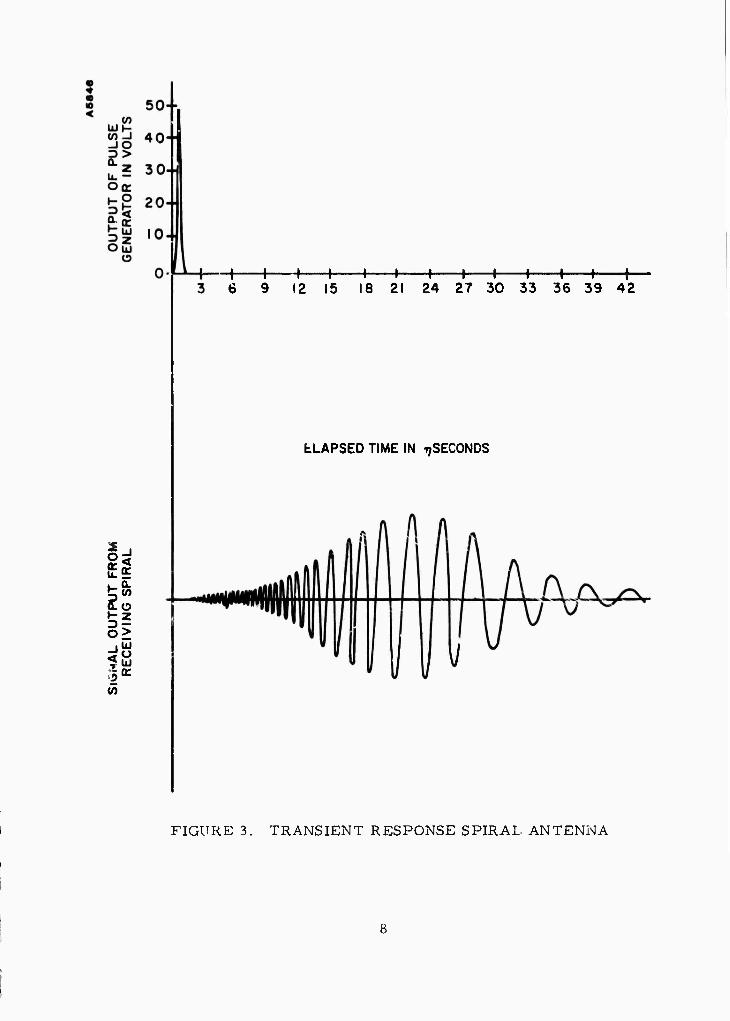
sketch of f . ■ input and outpat pulses transmitted by a pair of 6 inch diameter,
16 turn spiral antennas is shown in Figure 3. The dispersive property of
these antennas is evident from the diagram. The various frequency com-
pon-'nts arrive at different times, and the delay increases with a decrease
in frequency.
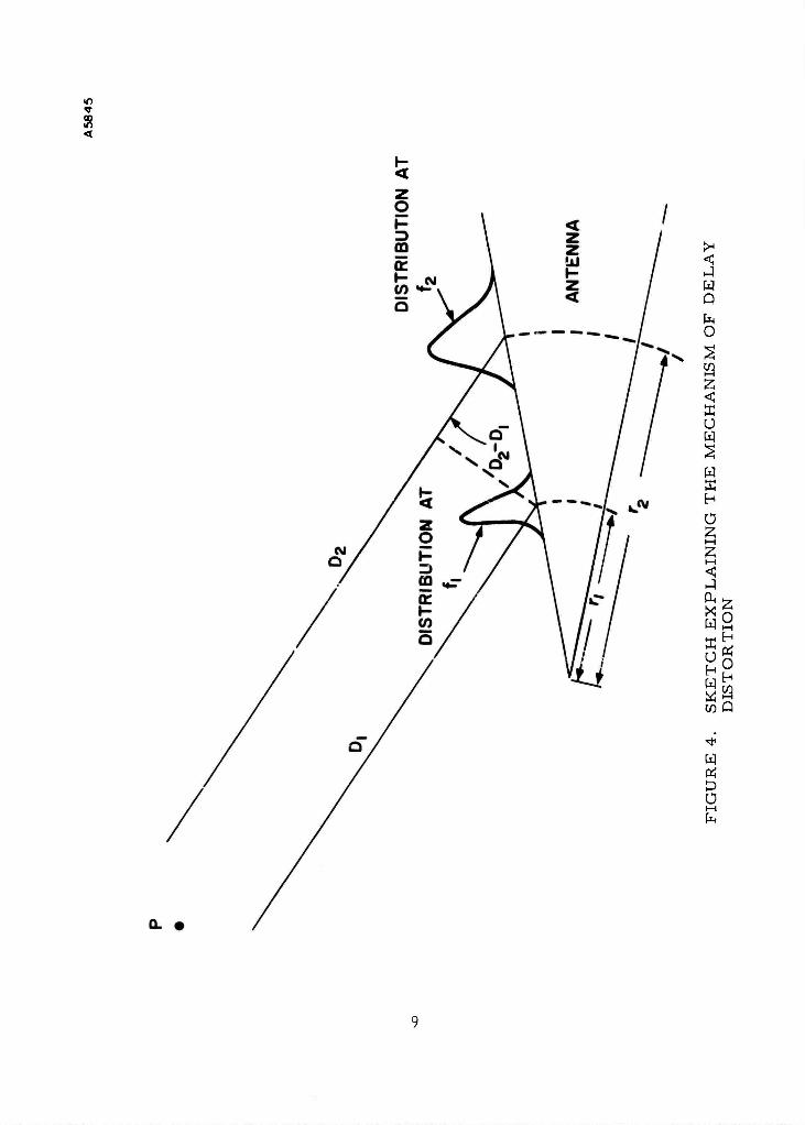
An explanation of this phenomenon wiU b^ offered in terms of a
simple model. Figure 4 is a sketch of a three-dimensional CS structure
and typical current amplitude distributions for frequencies f and f?, where
f^f^. Assume initially that there is no relative delay between the two
current envelopes corresponding to f, and f^ when excited by an impulse
source at the input. Let P be a point in the ^nr field. It is then clear that
the lower frequency (f^) component will experience ai added delay because
of the added path length D^-D,. In a practical antenna •liis delay distortion
is increased by 'he additional delay introduced by the geometry of the
structuie such as the transposition of LPD elements which increases the
phase distortion.
It is apparent from ihe above discussion that increase in the length
of an LPD with loaded elements at the low frequency end would tend to
increase the delay distortion as well as the phase ^.stortion. To obtain a
somewhat quantitative feel for the amount of phase distortion due to
increase in antenna length, it was recommended to RADC that this be cal-
culated from the far field phase vs. free ency response for two LPDA
models of different lengths but identical jand widths. It was mutually
decided that since RADC has a Sylvania computer progr^ i from an
r>rrf>'V>W>.W?V. F. i. AW nv W ^W Al.. ;\ü Vi* r.J. ^vxnw - A V» r-Ar^n^vx '^i ' jt^A f Ji rj\: j* ,~JI r>jt_ j4i\m'_nr\ji±i^. »^»JUL/LJ». ^-VL_^
i
I
$
to
V)
-\—I- + H h + H h -4- H h + 12 15 18 21 24 27 30 33 36 39 42
LLAPSED TIME IN tjSECONDS
FIGURE 3. TRANSIENT RESPONSE SPIRAL ANTENNA
nx^TU^wv "wHf^rjJarjir.«rj<.rj'-r\fj\*j'j,rsj-ffJ'J'si*:'sr>fifS\JW*siVi fjyj>rj_-<vx.-i:-<_TM.uti^i^jJ!--;.-^ -., J-^-J^W^HJLV^. i>n>v*/«<,-,< i. H'MH rw -
in
<
<
<
w Q
O
<
u w
y ä H Ü | i—i
I—I
PH
w
u
ia
O H
O h
w D Ü i—i
'LV u'.. Wl-VLVyVVWVUVi.'SAA/'JV'Vi.vK,J'-'^">.\A.,\,Vu%\'-. W-"V■/-■ NVaN\"«V«"\N"A:\'vV,\". ' %\^,V.,\%VK.\\äVLV\%V%L".VxV^^^X^V'AS.'^'L'JVi.U
anaLysis by Arens, Elfving, and Johnstone et. al. , that this calculation
would be performed at RADC. The results of the calculation are not part
of this report
3 • APPLICATION OF K-(3 DIAGRAM TO LPD ANTENNA
The dispersion characteristics of periodic structures, of which the
LPD antenna is an example, are commonly described in terms of a plot
of the propagation constant (3 versus the wave number k The plot is
referred to as the K-ß or w-ß liagram. A number of papers have been
published on the application of the K-:3 diagram of open periodic structures , ., , • * • ,- j , j- (8, 9, 10, 11, 12, 13, 14) to the analysis of periodic and log periodic antennas
In particular, the Brillouin diagram of the fini'^ uniformly periodic array
has been both calculated and measured The array is the direct counter-
part of the LPD array, and its behavior is typical of the expected perfor-
mance of an LP structure. The prototype LP structure is generated from
the uniform periodic structure by scaling the linear dimensions of each
succeeding cell by the scaling factor T,
The Brillouin diagram in its various forms offered a convenient way
of summarizing phase and amplitude performance alon^ a periodic structure.
Considerable work has been carried on in the extension of this theory of
uniform structures to apply to LP structures, and hence to further the
understanding of the principles of operation of the LP antennas, [t was
decided, in view of the amount of work underway that this portion of the
study be limited to a literature search to avoid duplication and conserve
resources of this contract.
Specifically, work was performed in this area at the antenna labora- (7 q m
tory of the University of Illinois, Reports by Mittra and Jones ,
Ingerson and Mayes
liography
, and Stephenson and Mayes are listed in the bib
The work consisted of theoretical, and experii. ental study of periodic
10
Viy/Vw ^j>iV»Arv,L'W\i\^ViVj%v*«/rfJ-AA^-V;.,'A.VJV.rj*.Vir^f\,\"^.(\> '>, r> M*J> MOU r>rat ^H">. rjtr^ r> r\> SJI PXr.Hr>,f> r> ••> rvx mi "> r>-^ r> P.» V
structures, both continuously scaled and log periodic. The use of K-ß dia-
grams and their significance in analyzing the structures was emphasized.
The multimode characteristics of the array structures was observed, and
the limitations this phenomenon places on the means of analyzing the struc-
tures noted. Good agreement between theoretical and experimental results
was indicated.
The use of the K-ß diagram and a generalization of Floquet's Theorem
for periodic structures to successfully predict the type of structures which
would exhibit the required broadband characteristics wa? discussed. In
particular the LPDA and conical spiral were analyzed, and showed good
agreement with the experimentally observed characteristics.
These papers indicated that the problem of designing a frequency
independent antenna with ideal transient response has not been solved.
It i... this author's opinion that the Multifilar Helix Antenna, reported on in
Part IT of this report, is a step closer to this goal.
4. CONCLUSION
The Log Periodic Dipole Antenna along with other Log Periodic and
continuouslv Scaled Antennas, is a highly dispersive structure. The dis-
persive properties of the LPD are increased when the low frequency dipoles
are foreshortened by means of reactive loading, due mainly to the resulting
increase in antenna length and number of elements.
The effects of the loading on the frequency response of the log perio-
dic dipolc antenna considered for an instantaneous bandwidth of 10% or
I MHz, whichever is greater, is relatively small. Since the phase is pro-
portional to the log of frequency, a 10% change in the frequency causes less
than a 6% deviation from phase linearity for the normal L. P, This devia-
tion is for phase corrected for front truncation of the L. P. (Ref. I, Sect.
3. 5, 2).
II
MBJBWSÄaÄTVywJ" .v/j". VJV ."AV/V'/vVw." A.v/>r/)A,rwvv»\iva iiiuwy^A/wwvwnR ^^J^JW^J-^JVM *-U XV W W WU KV *V ^J VJ W. W. H-J KV <MI
When the antenna elements are foreshortened, causing an increase
in T, and corresponding increase in antenna scaling i'actor T , the 1.0%
signal bandwidth results in further deviation from Linearity proportional to
the increase in T. A 10% increase in Twould result in an additional 2-3%
increase in the deviation from linear phase. This figure is again exclusive
of truncation effects and change in phase center of the antenna due to fre-
quency change
5 ■ RECOMMENDATIONS
a. The program to calculate the change in phase response due to in-
creased length of an LPD antenna should be run on the computer and re-
sults analyzed for effects on the overall array,
b. The transient response of the LPD element and of the array should
be investigated. Little has been published regarding the general analysis
of the transient response of wide-band antennas, and for the OUR applica-
tion it would seem to be an important factor in the system operation. La-
boratory measurements similar to those mentioned in this report could be
made on individual LPD models using various pulse shapes and pulse lengths.
In addition, an analysis program to relate the LPD response to the array
operation would be in order.
12
».--*. -. -M.J

REFERENCES
1. Carrel, R. L. , "Analysis and Design of the Log-Periodic Dipole Antenna", Technical Report No. 52, Antenna Laboratory University of Illinois, Urbana, Illinois.
2. Aiens, V. R., Elfving, C. T. , and Johnstone, D. L. et. al. , "H. F. Antenna Optimization Study", Technical Report No. RADC-TR-b7- 161, August 1967.
3. Elfving, Claes T. , "Foreshortened Log Periodic Dipole Array", Wescon 1963, Part I.
4. Bullock, Elfving, and Miller, "Log Periodic Antenna Techniques", A. D. 649838.
5. Di Fonzo, D T., "Reduced Size Log Periodic Antennas", Microwave Journal, Dec. 1964.
6. Stephenson, D. T. and Mayes, P. E. , "Log Periodic Helical Dipole Antennas", Wescon 1963.
7. Mittra, R. and Jones, K. E. , "Theoretical Brillouin (K-ß ) Diagram for Monopole and Dipole Arrays and Their Application to Log Periodic Antennas", Technical Report No. 70, Antenna Laboratory, University of Illinois.
8. Pulfer, J. K. , "Dispersive Properties of Broadband Antennas", Cor- respondence Proc. I. R. E. , Vol. 47, pp. 644, March 1961.
9. Mittr?, R. and Jones, K. E. , "Some Theoretical Aspects of Log Periodic and Continuously Scaled Antenna Designs", Technical Report No. 76, Antenna Laboratory, University of Illinois.
10. Ingerson, P. G. and Mayes, P. E. , "Dispt sion Properties of Linear Dipole Arrays", Antenna Laboratory Rr rt No. 66-2, University of Illinois.
11. Mittra, R. and Jones, K. E. , "Some Interpretations and Applications of the K-(3 Diagram", Technical Report No. 84, Antenna Laboratory, University of Illinois.
12. Kieburtz, Richard B. , "Analysis and Synthesis of Aperture Fields of Log Periodic Antennas", Scientific Report No. 2, State University of New York at Stony Brook.
13
•*-.'■. ' . ■•- * ■ ^ " - ■ v ^M - .L ^ ■ , »-.»-.-■-■ -'■4 - 1 ■ ^-C - m '. 1 - *r n_u -. t—l_j i_4—^^

r I
1 %
L
13, Sun, David F-D and Kieburtz, R. B. , "Dispersion Relations of Per- iodic and Log Periodic Dipole Arrays with Parasitic Elements", Technical Report No. 92, College of Engineering, State University of New York at Stony Brook.
14. Du Hamel, R. H. and Barry, D. G. , "Logarithmically Periodic Antenna Array", I. R. E. Wescor Convention Record, Parti, 1958.
14
'.•W-CA V\ V V\Vi VlV, IIMV- , .>..'• .> .-- .> --■ - ME: '"■<>'• ^BE ■ ■-/■■'Vt .-.. -t . m .
UNCLASSIFIED Security Classification
I DOCUMENT CONTROL DATA R&D
fSecurify classification ot title, body ot abstract and indexing annotation must he entered when the overall report is classified)
1 ORiGINATINC A c T l v i T Y fCorporafe au(/ior;
Syracuse University Research Corporation Merrill Lane, University Heights Syracuse, New York 13210
12«. REPORT SECURITY CLASSIFICATION
Unclassified 2b. GROUP
3 REPORT TITLE
ARPA ANTENNA STUDY (U) PART I DISPERSION STUDY
ARPA ANTENNA STUDY (U) PART II MCH ELEMENT INVESTIGATION
*• DEAfwRLPT MOMf ,5 CTVpe of report and inclusive dates)
\i R9
i l
5 AU THOR(S» (F/rsf name, middle initial, last name)
Robert K. Greenouqh
6. REPORT DATE
1969 March 4 7a. TOTAL NO. OF PAGES
60 76. NO, OF REFS
16 8a. CONTRACT OR GRANT NO.
F 30602-67-C-0138 b. PROJEC T NO.
c. ARPA Order No. 943
9a. ORIGINATOR'S REPORT MJMBERIS)
Part I - SPL TR 69-15 Part II - SPL TR 69-16
9b. o THER REPORT NO(S) (Any other numbers that may be assigned this report)
10. DISTRIBUTION STATEMENT
This document is subject to special export controls and each transmittal to foreign governments or foreign nationals may be made only with prior approval of RADC (EMATA) GAFB, N.Y. 13440.
11. SUPPLEMENTARY NOTES
Monitored by: Rome Air Development Center (EMATA) Griffiss Air Force Base, N.Y. 13440
12. SPONSORING MILITARY ACTIVITY
Advanced Research Projects Agency Washington, D. C. 20301
8
A'
V
i
I
13. ABSTRACT
The purpose of this contract was to perform studies for Rome Air Development Center and the Advanced Research Projects Agency in the antenna development program for the Big Push Radar. The contribution by Syracuse University Research Corpora- tion was in the form of man power and materials applied to specific antenna problems specified by Rome Air Development Center, and relating to the 0HP program.
The first task under this contract was to consider the dispersive properties of the Log Periodic Dipole Array element when some of the dipoles were reactively loaded. This effort was primarily a literature search to determine what has been accomplished in loading of LPD elements, and in the study of dispersive properties of frequency independent antennas.
The task covered in Part II of this report was to investigate the feasibility of the Multifilar Counterwound Helix as an element of a wideband array. This included design of an element and measurement of its parameters over a four to one frequency band. The result of this study was to be a model of the antenna with measured data characterizing its performance.
I DD FORM 1 NO V 65 1473 UNCLASSIFIED
Security Classificdtion
UNCLASSIFIED Security Classification
KEY WO RDS
Antenna, Log Periodic, Helix, Dispersion
UNCLASSIFIED Security Classification
^v^>\.>vvkvvv.vy.wv.v>^:^^v->>j.>>v^-w--v^'^v->--> ■■-v-.•-..'■ -•■ .-• /• /•r-...-v--r- -•■■'•'-'■••-•^--"V-V-'1.--V-'/-^-^---.--\--V-".-'".T^V