Embed Size (px)
Citation preview
HSDPA Engineering Guide
Document number: UMT/IRC/APP/014654 Document issue: 01.11 / EN Document status: Standard Date: 10/Oct/2006
INTERNAL Document
Copyright© 2005 Nortel Networks, All Rights Reserved.
Printed in France
NORTEL CONFIDENTIAL
The information contained in this document is the property of Nortel Networks. Except as specifically authorized in writing by Nortel Networks, the holder of this document shall keep the information contained herein confidential and shall protect same in whole or in part from disclosure and dissemination to third parties and use same for evaluation, operation and maintenance purposes only.
The content of this document is provided for information purposes only and is subject to modification. It does not constitute any representation or warranty from Nortel Networks as to the content or accuracy of the information contained herein, including but not limited to the suitability and performances of the product or its intended application.
This is the Way. This is Nortel, Nortel, the Nortel logo, and the Globemark are trademarks of Nortel Networks. All other trademarks are the property of their owners.
HSDPA Engineering Guide
Nortel confidential
UMT/IRC/APP/014654 01.11 / EN Standard 10/Oct/2006 Page 2/169
PUBLICATION HISTORY
10/Oct/2006
Issue 01.11 / EN, Standard
Document update
29/Jul/2006
Issue 01.10 / EN, Standard
Document update after Internal Review
07/Jul/2006
Issue 01.09 / EN, Standard
Document update / UA4.2 ChR with ETP results
31/May/2006
Issue 01.08 / EN, Standard
Document update / UA4.2 ChR
28/Apr/2006
Issue 01.07 / EN, Preliminary
Document update / UA4.2 pre-ChR
20/Jan/2006
Issue 01.06 / EN, Preliminary
Document update / UA4.2 CuR
25/Nov/2005
Issue 01.05 / EN, Draft
Document update / External Version
18/Oct/2005
Issue 01.04 / EN, Draft
Document updated after review for external version / External Version
HSDPA Engineering Guide
Nortel confidential
UMT/IRC/APP/014654 01.11 / EN Standard 10/Oct/2006 Page 3/169
04/Oct/2005
Issue 01.03 / EN, Draft
Document updated for W.39 Load / External Version
02/Sep/2005
Issue 01.02 / EN, Draft
Document updated after review
19/Aug/2005
Issue 01.01 / EN, Draft
Document Creation
HSDPA Engineering Guide
Nortel confidential
UMT/IRC/APP/014654 01.11 / EN Standard 10/Oct/2006 Page 4/169
CONTENTS
1 INTRODUCTION..........................................................................................................................10 1.1 OBJECT..................................................................................................................................10 1.2 SCOPE OF THIS DOCUMENT .....................................................................................................10 1.3 NOMENCLATURE.....................................................................................................................10
2 RELATED DOCUMENTS ............................................................................................................13 2.1 REFERENCE DOCUMENTS........................................................................................................13
3 HSDPA OVERVIEW ....................................................................................................................14 3.1 SYSTEM OVERVIEW.................................................................................................................14
3.1.1 New transport and physical channels ...........................................................................16 3.1.2 Fast link adaptation .......................................................................................................18 3.1.3 Fast Retransmission Mechanism (HARQ) ....................................................................19 3.1.4 Fast scheduling .............................................................................................................24
3.2 DEPLOYEMENT SCENARIOS .....................................................................................................28 3.2.1 Dual Carrier ...................................................................................................................28 3.2.2 Single carrier .................................................................................................................29
3.3 HSDPA RESOURCES..............................................................................................................29 3.3.1 OVSF Codes .................................................................................................................29 3.3.2 Power ............................................................................................................................30 3.3.3 HSDPA Channels & CQI...............................................................................................31
3.4 UE CATEGORIES ....................................................................................................................38 3.5 CALL MANAGEMENT................................................................................................................39
3.5.1 Traffic segmentation......................................................................................................39 3.5.2 HSDPA CAC .................................................................................................................43 3.5.3 Call Setup (Dataflow) ....................................................................................................45 3.5.4 Call Release (Dataflow) ................................................................................................47 3.5.5 HSDPA related Transitions ...........................................................................................48
4 HSDPA CONFIGURATION .........................................................................................................53 4.1 RAN MODEL AND PARAMETERS ..............................................................................................53
4.1.1 RRM Impact ..................................................................................................................53 4.1.2 BTS Impact....................................................................................................................67 4.1.3 IuB Impact .....................................................................................................................69
4.2 HSDPA ACTIVATION...............................................................................................................70
6 UA4.2 HSDPA SPECIFIC FEATURES & IMPACT ON EXISTING ALGORITHMS ...................72 6.1 ALWAYS ON ...........................................................................................................................72
6.1.1 Mechanism....................................................................................................................72 6.1.2 Activation & Mode .........................................................................................................72 6.1.3 Reminder for timer usage..............................................................................................76 6.1.4 Parameters Settings and Recommendations ...............................................................76
6.2 IRM ALGORITHMS...................................................................................................................77 6.2.1 Irm Scheduling Downgrade/Upgrade Interworking .......................................................77 6.2.2 iRM Cac/iRM Pre-Emption Interworking .......................................................................77
HSDPA Engineering Guide
Nortel confidential
UMT/IRC/APP/014654 01.11 / EN Standard 10/Oct/2006 Page 5/169
6.2.3 RB Adaptation Interworking ..........................................................................................77 6.3 MOBILITY PROCEDURES..........................................................................................................78
6.3.1 Intra-Frequency Mobility................................................................................................78 6.3.2 Inter-Frequency Mobility................................................................................................81 6.3.3 Inter-System Mobility.....................................................................................................81 6.3.4 U-Plane Traffic Handling ...............................................................................................82 6.3.5 Summary of inter-frequency and inter-RAT scenarios..................................................83
6.4 POWER MANAGEMENT ............................................................................................................84 6.4.1 Introduction....................................................................................................................84 6.4.2 Flexible power management feature.............................................................................84 6.4.3 HS-SCCH power control feature...................................................................................99 6.4.4 Parameters Settings and Recommendations ............................................................ 100
6.5 TRANSPORT ........................................................................................................................ 104 6.5.1 Iu User Traffic Conformance...................................................................................... 104 6.5.2 Iub Bandwidth Limitation ............................................................................................ 107
6.6 OTHER FEATURES ............................................................................................................... 117 6.6.1 HSDPA Service Indicator ........................................................................................... 117
7 HSDPA THROUGHPUT OPTIMIZATION ................................................................................ 118 7.1 POWER ALLOCATION AND USER THROUGHPUT...................................................................... 118 7.2 CQI SELECTION AT UE ........................................................................................................ 120 7.3 CQI ADJUSTMENT BASED ON BLER...................................................................................... 121 7.4 BTS CREDIT ALLOCATION..................................................................................................... 123 7.5 HARQ RETRANSMISSIONS ................................................................................................... 123 7.6 RLC SETTINGS FOR UL DCH............................................................................................... 124 7.7 DL RLC SETTINGS FOR HSDPA........................................................................................... 127 7.8 OPTIMISED TCP SETTINGS................................................................................................... 127 7.9 PARAMETERS SETTINGS ...................................................................................................... 128
8 HSDPA CAPACITY ASPECTS ................................................................................................ 129 8.1 CEM CAPACITY................................................................................................................... 129
8.1.1 Product limits.............................................................................................................. 129 8.1.2 Capacity analysis ....................................................................................................... 133
9 PRODUCT RECOMMENDATIONS.......................................................................................... 155 9.1 HSDPA COMPATIBILITY WITH UTRAN NETWORK ELEMENTS................................................. 155
9.1.1 RNC............................................................................................................................ 155 9.1.2 BTS ............................................................................................................................ 155
9.2 HSDPA COMPATIBILITY WITH MODULES ............................................................................... 156 9.2.1 RNC............................................................................................................................ 156 9.2.2 BTS ............................................................................................................................ 157
9.3 HSDPA SYSTEM IMPACT................................................................................................ 157 9.3.1 RNC functions ............................................................................................................ 158 9.3.2 BTS functions............................................................................................................. 158
9.4 HSDPA AND UTRAN INTERFACES ...................................................................................... 163 9.4.1 Radio Interface........................................................................................................... 163 9.4.2 IuB .............................................................................................................................. 163 9.4.3 Iu-CS .......................................................................................................................... 164
HSDPA Engineering Guide
Nortel confidential
UMT/IRC/APP/014654 01.11 / EN Standard 10/Oct/2006 Page 6/169
9.4.4 Iu-PS .......................................................................................................................... 164 9.4.5 Iu-R............................................................................................................................. 164 9.4.6 Iu-PC .......................................................................................................................... 164
10 ABBREVIATIONS AND DEFINITIONS.................................................................................... 165 10.1 ABBREVIATIONS................................................................................................................... 165 10.2 DEFINITIONS........................................................................................................................ 168
HSDPA Engineering Guide
Nortel confidential
UMT/IRC/APP/014654 01.11 / EN Standard 10/Oct/2006 Page 7/169
TABLES Table 1: Number of processes per UE category 19 Table 2: RV coding for 16QAM 20 Table 3: RV coding for QPSK 20 Table 4: RV update table in the MIR case (Trv[i]) 21 Table 5: RV update table in the PIR case (Trv[i]) 21 Table 6: UE capabilities 38 Table 7: RB Configuration and system behaviour 39 Table 8: RRC Connection Request and suitable layer 42 Table 9: HSDPA related Transitions 49 Table 10 : Always-on timer usage 76 Table 11: CQI update summary 96 Table 12: CQI Mapping 97 Table 13: HS-SCCH power offset table according the reported CQI 100 Table 14: UL rate required vs. DL rate 127 Table 15: Parameters summary for optimized throughput 128 Table 16: H-BBU limitations 129 Table 17: H-BBU capacity details 130
HSDPA Engineering Guide
Nortel confidential
UMT/IRC/APP/014654 01.11 / EN Standard 10/Oct/2006 Page 8/169
FIGURES Figure 1: R99 principle ......................................................................................................................................... 14 Figure 2: HSDPA principle................................................................................................................................... 14 Figure 3: HSDPA layer2/layer1 flows .................................................................................................................. 15 Figure 4: Mac-hs entity on UTRAN side .............................................................................................................. 15 Figure 5: Transport channel configuration............................................................................................................ 17 Figure 6: HSDPA channels and associated R99 channels..................................................................................... 17 Figure 7: Example of AMC : Throughput versus Ior/Ioc (radio condition) .......................................................... 18 Figure 8: RV parameters assignment algorithm.................................................................................................... 22 Figure 9: ACK/NACK/DTX management for HARQ processes.......................................................................... 23 Figure 10: Scheduler overview ............................................................................................................................. 25 Figure 11: HSDPA on dedicated layer.................................................................................................................. 28 Figure 12: Example of OVSF tree usage with HSDPA ........................................................................................ 29 Figure 13: OVSF allocation strategy..................................................................................................................... 30 Figure 14: Timing relationship at NodeB between physical channels .................................................................. 31 Figure 15: HS-SCCH structure ............................................................................................................................. 32 Figure 16: HS-PDSCH structure........................................................................................................................... 32 Figure 17: HS-DPCCH structure .......................................................................................................................... 33 Figure 18: CQI Processing.................................................................................................................................... 33 Figure 19: CQI offset computation based on BLER ............................................................................................. 36 Figure 20: Scheduler and Flow Control disabled.................................................................................................. 37 Figure 21: HSDPA Call setup / initial connection (Cell_DCH)............................................................................ 45 Figure 22: HSDPA Call setup / RAB allocation phase (call establishment done on DCH).................................. 46 Figure 23: Call release (RAB release case)........................................................................................................... 48 Figure 24: RRM new HSDPA subtree .................................................................................................................. 53 Figure 25: FDDCell HSDPA Related new objects ............................................................................................... 53 Figure 26: HSDPARncConf subtree ..................................................................................................................... 55 Figure 27: HSDPA Radio Bearer subtree ............................................................................................................. 58 Figure 28: HSDSCHx4SRBDCCH3_4K subtree.................................................................................................. 61 Figure 29: HSDPA RLC subtree........................................................................................................................... 63 Figure 30: HSDPA UsHoConf subtree ................................................................................................................. 64 Figure 31: HSDPA BTS new object ..................................................................................................................... 67 Figure 32: IuB HSDPA new object....................................................................................................................... 69 Figure 33: Always-on for HSDPA (degraded2AlwaysOn mode) ......................................................................... 74 Figure 34: Always-on for HSDPA (releaseOnly mode)........................................................................................ 75 Figure 35: HS-DSCH link is deleted and re-established on new primary (nominal case) .................................... 80 Figure 36: Summary of Inter-freq/inter-RAT mobility ......................................................................................... 83 Figure 37: Power allocation at RNC level ............................................................................................................ 85 Figure 38: Physical shared channel reconfiguration message ............................................................................... 86 Figure 39: Power allocation at NodeB level ......................................................................................................... 87 Figure 40: Transmitted carrier power (on the left) and averaged HSDPA power (on the right) ........................... 89 Figure 41: Common measurement ........................................................................................................................ 89 Figure 42: Power measurement process................................................................................................................ 90 Figure 43: Power distribution between HS-DSCH and HS-SCCH channels ........................................................ 91 Figure 44: measurementPowerOffset transmission............................................................................................... 92 Figure 45: HS-DSCH power management for 1st transmission............................................................................ 94 Figure 46: Mac-hs transport block adaptation according to the number of Mac-d PDU to transmit .................... 96 Figure 47: HS-DSCH power management for retransmission .............................................................................. 98 Figure 48: Remaining power for multi-users per TTI scheduling......................................................................... 99 Figure 49: HS-SCCH power control overview ................................................................................................... 100 Figure 50: Traffic Conformance Algorithm........................................................................................................ 105 Figure 51: discard and backpressure thresholds.................................................................................................. 109 Figure 52: example of traffic regulation with backpressure................................................................................ 110 Figure 53: feature behaviour on Iur .................................................................................................................... 111 Figure 54: example of transport topologies "with ATM priority"....................................................................... 112 Figure 55: example of transport topology "without ATM priority" .................................................................... 112
HSDPA Engineering Guide
Nortel confidential
UMT/IRC/APP/014654 01.11 / EN Standard 10/Oct/2006 Page 9/169
Figure 56: User multiplexing in Code and Time domains .................................................................................. 118 Figure 57: User throughput vs. HSDPA power, UE cat 6................................................................................... 119 Figure 58: HARQ BLER vs. User RLC Throughput, UE cat 12, drive test........................................................ 121 Figure 59: User throughput vs. BLER on HS-PDSCH, UE cat 12 ..................................................................... 122 Figure 60: User throughput vs. status prohibit timer, UE cat 6........................................................................... 125 Figure 61: User throughput vs. polling timer vs. UL BLER............................................................................... 125 Figure 62: User throughput vs. receive window size at UE................................................................................ 126 Figure 68: H-BBU ressources allocation modes ................................................................................................. 134 Figure 69: iCEM consumption for a PS RB DL 128 kbps / UL 384 kbps (R99 Case) ....................................... 135 Figure 70: iCEM consumption for a PS RB HSDPA / UL 128 kbps (HSDPA Case)......................................... 136 Figure 71 : Comparison between the CEM R99 Capacity and the CEM HSDPA Capacity for same input traffic
and same CEM configuration (same hardware) .......................................................................................... 136 Figure 72: CEM Capacity vs. HSDPA Penetration............................................................................................. 137 Figure 73: CEM Admission Blocking type (R99 or HSDPA) versus HSDPA Penetration Factor ..................... 138 Figure 74: CEM Capacity figures for different configurations depending on the HSDPA penetration factor (UL
64 kbps)....................................................................................................................................................... 138 Figure 75: Admission blocking by service vs HSDPA penetration factor .......................................................... 140 Figure 76: CEM Capacity figures for different configurations depending on the HSDPA penetration factor (UL
128 kbps)..................................................................................................................................................... 141 Figure 84 : H-BBU/D-BBU Allocation per BBU (Example) ............................................................................. 161
HSDPA Engineering Guide
Nortel confidential
UMT/IRC/APP/014654 01.11 / EN Standard 10/Oct/2006 Page 10/169
1 INTRODUCTION
1.1 OBJECT
The objective of this document is to describe from an engineering point of view the HSDPA system.
This includes a system description, configuration aspect and optimization settings.
1.2 SCOPE OF THIS DOCUMENT
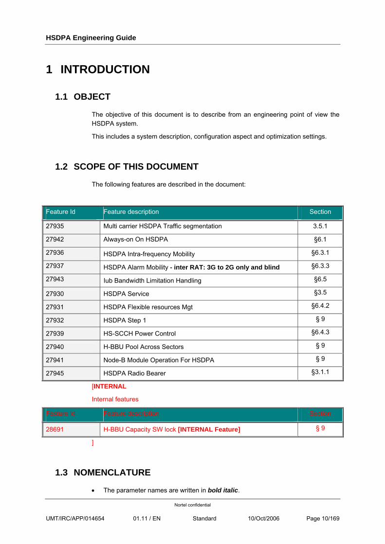
The following features are described in the document:
Feature Id Feature description Section
27935 Multi carrier HSDPA Traffic segmentation 3.5.1
27942 Always-on On HSDPA §6.1
27936 HSDPA Intra-frequency Mobility §6.3.1
27937 HSDPA Alarm Mobility - inter RAT: 3G to 2G only and blind §6.3.3
27943 Iub Bandwidth Limitation Handling §6.5
27930 HSDPA Service §3.5
27931 HSDPA Flexible resources Mgt §6.4.2
27932 HSDPA Step 1 § 9
27939 HS-SCCH Power Control §6.4.3
27940 H-BBU Pool Across Sectors § 9
27941 Node-B Module Operation For HSDPA § 9
27945 HSDPA Radio Bearer §3.1.1
[INTERNAL
Internal features
Feature Id Feature description Section
28691 H-BBU Capacity SW lock [INTERNAL Feature] § 9
]
1.3 NOMENCLATURE
• The parameter names are written in bold italic.
HSDPA Engineering Guide
Nortel confidential
UMT/IRC/APP/014654 01.11 / EN Standard 10/Oct/2006 Page 11/169
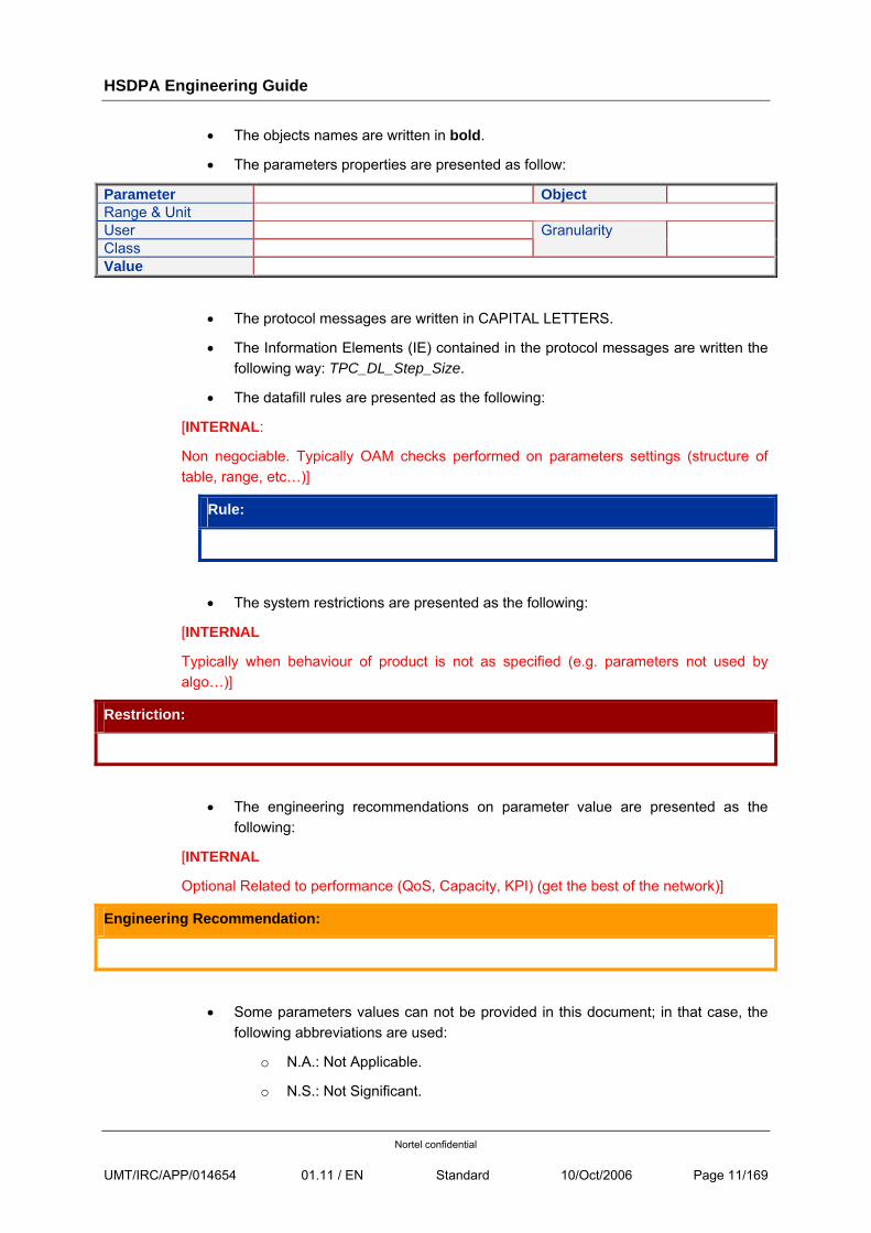
• The objects names are written in bold.
• The parameters properties are presented as follow:
Parameter Object Range & Unit User Class
Granularity
Value
• The protocol messages are written in CAPITAL LETTERS.
• The Information Elements (IE) contained in the protocol messages are written the following way: TPC_DL_Step_Size.
• The datafill rules are presented as the following:
[INTERNAL:
Non negociable. Typically OAM checks performed on parameters settings (structure of table, range, etc…)]
Rule:
• The system restrictions are presented as the following:
[INTERNAL
Typically when behaviour of product is not as specified (e.g. parameters not used by algo…)]
Restriction:
• The engineering recommendations on parameter value are presented as the following:
[INTERNAL
Optional Related to performance (QoS, Capacity, KPI) (get the best of the network)]
Engineering Recommendation:
• Some parameters values can not be provided in this document; in that case, the following abbreviations are used:
o N.A.: Not Applicable.
o N.S.: Not Significant.
HSDPA Engineering Guide
Nortel confidential
UMT/IRC/APP/014654 01.11 / EN Standard 10/Oct/2006 Page 12/169
o O.D.: Operator Dependant (depends on operator network specific configuration. Example: addressing parameters).
HSDPA Engineering Guide
Nortel confidential
UMT/IRC/APP/014654 01.11 / EN Standard 10/Oct/2006 Page 13/169
2 RELATED DOCUMENTS
2.1 REFERENCE DOCUMENTS
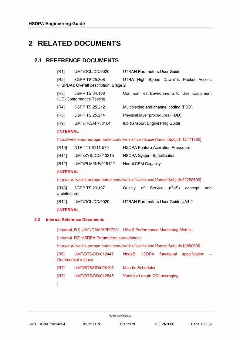
[R1] UMT/DCL/DD/0020 UTRAN Parameters User Guide
[R2] 3GPP TS 25.308 UTRA High Speed Downlink Packet Access (HSPDA); Overall description; Stage 2
[R3] 3GPP TS 34.108 Common Test Environments for User Equipment (UE) Conformance Testing
[R4] 3GPP TS 25.212 Multiplexing and channel coding (FDD)
[R5] 3GPP TS 25.214 Physical layer procedures (FDD)
[R9] UMT/IRC/APP/0164 Iub transport Engineering Guide
[INTERNAL
http://livelink-eur.europe.nortel.com/livelink/livelink.exe?func=ll&objId=12171760]
[R10] NTP 411-8111-575 HSDPA Feature Activation Procedure
[R11] UMT/SYS/DD/013319 HSDPA System Specification
[R12] UMT/PLM/INF/018122 Nortel CEM Capacity
[INTERNAL
http://eur-livelink.europe.nortel.com/livelink/livelink.exe?func=ll&objId=22288506]
[R13] 3GPP TS 23.107 Quality of Service (QoS) concept and architecture
[R14] UMT/DCL/DD/0020 UTRAN Parameters User Guide UA4.2
[INTERNAL
2.2 Internal Reference Documents
[Internal_R1] UMT/OAM/APP/7291 UA4.2 Performance Monitoring Metrics
[Internal_R2] HSDPA Parameters spreadsheet:
http://eur-livelink.europe.nortel.com/livelink/livelink.exe?func=ll&objId=10580596
[R6] UMT/BTS/DD/012447 NodeB HSDPA functional specification – Commercial release
[R7] UMT/BTS/DD/008196 Mac-hs Scheduler
[R8] UMT/BTS/DD/012545 Variable Length CQI averaging
]
HSDPA Engineering Guide
Nortel confidential
UMT/IRC/APP/014654 01.11 / EN Standard 10/Oct/2006 Page 14/169
3 HSDPA OVERVIEW
3.1 SYSTEM OVERVIEW
3GPP has standardized HSDPA in Release 5 [R2] in order to increase maximum user throughput for downlink packet data (streaming, interactive and background traffic classes) and decrease downlink packet transmission delay. This Release 5 is fully compatible with the previous Release 99 (R99).
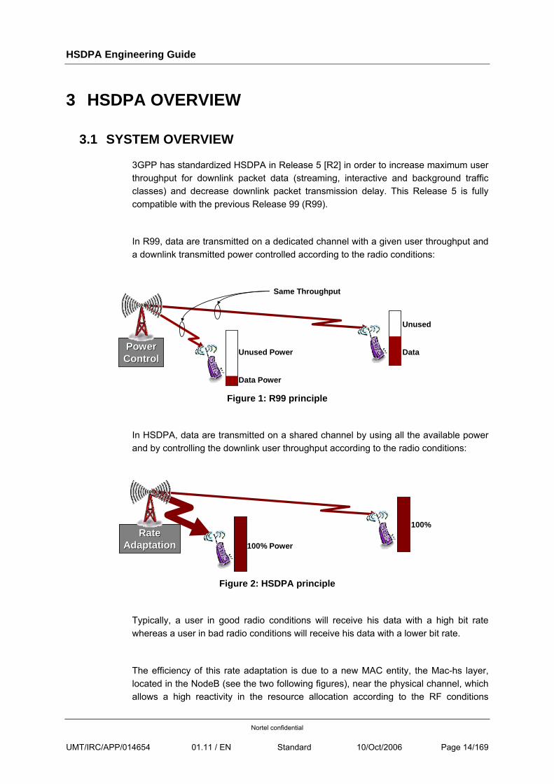
In R99, data are transmitted on a dedicated channel with a given user throughput and a downlink transmitted power controlled according to the radio conditions:
PowerPowerControlControl
Data Power
Unused Power Data
Unused
Same Throughput
Figure 1: R99 principle
In HSDPA, data are transmitted on a shared channel by using all the available power and by controlling the downlink user throughput according to the radio conditions:
RateRateAdaptationAdaptation 100% Power
100%
Figure 2: HSDPA principle
Typically, a user in good radio conditions will receive his data with a high bit rate whereas a user in bad radio conditions will receive his data with a lower bit rate.
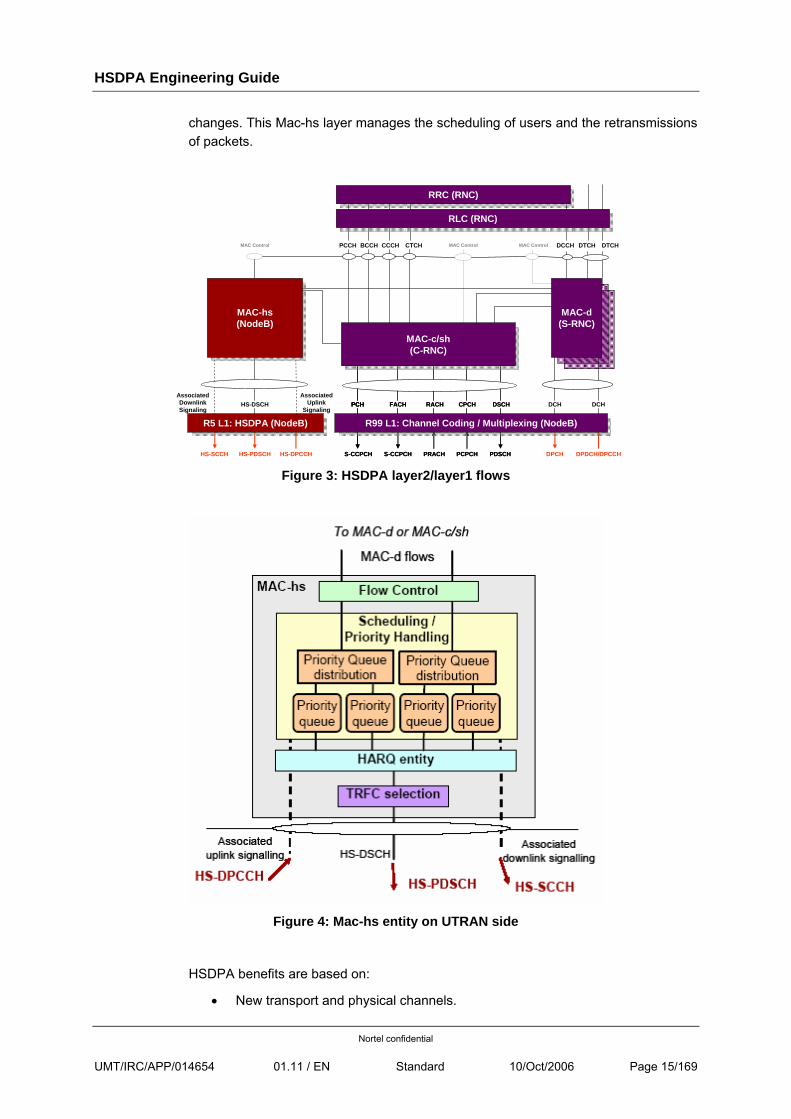
The efficiency of this rate adaptation is due to a new MAC entity, the Mac-hs layer, located in the NodeB (see the two following figures), near the physical channel, which allows a high reactivity in the resource allocation according to the RF conditions
HSDPA Engineering Guide
Nortel confidential
UMT/IRC/APP/014654 01.11 / EN Standard 10/Oct/2006 Page 15/169
changes. This Mac-hs layer manages the scheduling of users and the retransmissions of packets.
HS-DSCHAssociated
UplinkSignaling
AssociatedDownlinkSignaling
DCCH DTCHDTCHMAC Control MAC ControlCCCH CTCHBCCHPCCHMAC Control
RRC (RNC)RRC (RNC)
RLC (RNC)RLC (RNC)
HS-PDSCH
FACH
S-CCPCH
FACH
S-CCPCH
RACH
PRACH
RACH
PRACH
DSCH
PDSCH
DSCH
PDSCH
DCH
DPCH
CPCH
PCPCH
CPCH
PCPCH
PCH
S-CCPCH
PCHPCH
S-CCPCHHS-DPCCHHS-SCCH
MAC-c/sh(C-RNC)
MAC-c/sh(C-RNC)
DCH
DPDCH/DPCCH
R99 L1: Channel Coding / Multiplexing (NodeB)R99 L1: Channel Coding / Multiplexing (NodeB)R5 L1: HSDPA (NodeB)R5 L1: HSDPA (NodeB)
MAC-d(S-RNC)
MAC-hs(NodeB)
MAC-hs(NodeB)
Figure 3: HSDPA layer2/layer1 flows
Figure 4: Mac-hs entity on UTRAN side
HSDPA benefits are based on:
• New transport and physical channels.

HSDPA Engineering Guide
Nortel confidential
UMT/IRC/APP/014654 01.11 / EN Standard 10/Oct/2006 Page 16/169
• Fast link adaptation.
• Fast retransmission mechanism (HARQ).
• Fast scheduling.
3.1.1 NEW TRANSPORT AND PHYSICAL CHANNELS
In R99, downlink data are sent on a DCH (Dedicated CHannel) which is mapped on the DPDCH (Dedicated Physical Data CHannel). In HSDPA, downlink data are sent on a HS-DSCH (High Speed – Downlink Shared CHannel) which is mapped on one or several HS-PDSCH (High Speed – Physical Downlink Shared CHannel). Users are multiplexed on the HS-DSCH channel in time and code. Transmission is based on shorter sub-frames of 2ms (TTI) instead of 10ms in R99.
In downlink, the HS-PDSCH are transmitted with the HS-SCCH (High Speed – Shared Control CHannel) channel. This channel is broadcasted over the cell but his information concerned only the user who has to receive the HS-PDSCH. The HS-SCCH allows the user to know if the HS-PDSCH are for him and to decode them correctly.
Radio conditions information and acknowledgement are reported by the UE to the NodeB through the HS-DPCCH channel. This channel allows the NodeB to adapt the downlink data rate and to manage retransmission process. The HS-DPCCH is divided in two parts. The first one is the Channel Quality Indicator (CQI) which is a value between 1 and 30 characterizing the radio conditions (1 = bad radio conditions and 30 = good radio conditions). The second one is the acknowledgement information: if data are well received by the UE, the UE sends to the NodeB an Ack, otherwise a Nack.
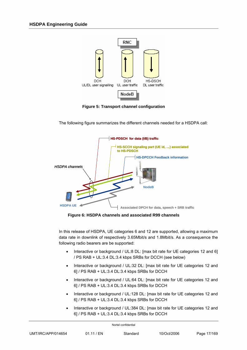
HS-DSCH channel is always associated to a DCH. This induces the following transport channel configuration for any UE established in HSDPA (see the following figure):
• one DCH handling the signaling in both UL and DL,
• one DCH transporting the UL traffic,
• one HS-DSCH for the DL traffic.
HSDPA Engineering Guide
Nortel confidential
UMT/IRC/APP/014654 01.11 / EN Standard 10/Oct/2006 Page 17/169
Figure 5: Transport channel configuration
The following figure summarizes the different channels needed for a HSDPA call:
NodeB
HSDPA UE
HS-PDSCH for data (I/B) trafficHS-PDSCH for data (I/B) traffic
HSDPA channelsHSDPA channels
HS-SCCH signaling part (UE id, …) associated to HS-PDSCHHS-SCCH signaling part (UE id, …) associated to HS-PDSCH
HS-DPCCH Feedback informationHS-DPCCH Feedback information
Associated DPCH for data, speech + SRB trafficAssociated DPCH for data, speech + SRB traffic Figure 6: HSDPA channels and associated R99 channels
In this release of HSDPA, UE categories 6 and 12 are supported, allowing a maximum data rate in downlink of respectively 3.65Mbit/s and 1.8Mbit/s. As a consequence the following radio bearers are be supported:
• Interactive or background / UL:8 DL: [max bit rate for UE categories 12 and 6] / PS RAB + UL:3.4 DL:3.4 kbps SRBs for DCCH (see below)
• Interactive or background / UL:32 DL: [max bit rate for UE categories 12 and 6] / PS RAB + UL:3.4 DL:3.4 kbps SRBs for DCCH
• Interactive or background / UL:64 DL: [max bit rate for UE categories 12 and 6] / PS RAB + UL:3.4 DL:3.4 kbps SRBs for DCCH
• Interactive or background / UL:128 DL: [max bit rate for UE categories 12 and 6] / PS RAB + UL:3.4 DL:3.4 kbps SRBs for DCCH
• Interactive or background / UL:384 DL: [max bit rate for UE categories 12 and 6] / PS RAB + UL:3.4 DL:3.4 kbps SRBs for DCCH
HSDPA Engineering Guide
Nortel confidential
UMT/IRC/APP/014654 01.11 / EN Standard 10/Oct/2006 Page 18/169
The maximum bit rate that can be achieved in the UL can be the bottleneck for the maximum bit rate achievable in the DL. For instance, excessive delay of RLC/TCP acknowledgements due to low bandwidth in the UL will limit the DL throughput, even if the RF conditions would allow more.
In UA04.2, Nortel implements the RB adaptation feature that dynamically adapts the UL bit rate to the amount of traffic carried over the RB. UL adaptation ranges from 32kbps up to 384kbps, but 8kbps is not eligible. Therefore, although UL:8 DL:[max bit rate for UE categories 12 and 6] will be allocated by the RNC if UL:8 is explicitly requested in the RAB assignment, it is not recommended to do so, otherwise the user will experience low throughput in the DL.
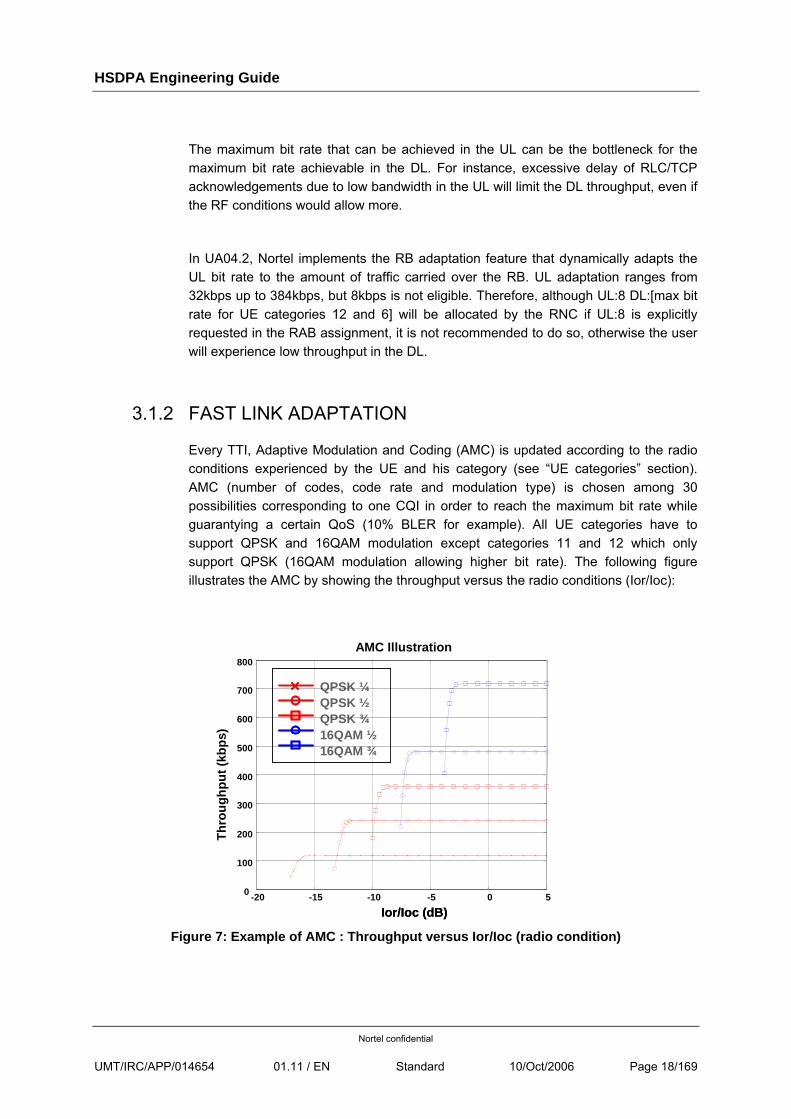
3.1.2 FAST LINK ADAPTATION
Every TTI, Adaptive Modulation and Coding (AMC) is updated according to the radio conditions experienced by the UE and his category (see “UE categories” section). AMC (number of codes, code rate and modulation type) is chosen among 30 possibilities corresponding to one CQI in order to reach the maximum bit rate while guarantying a certain QoS (10% BLER for example). All UE categories have to support QPSK and 16QAM modulation except categories 11 and 12 which only support QPSK (16QAM modulation allowing higher bit rate). The following figure illustrates the AMC by showing the throughput versus the radio conditions (Ior/Ioc):
QPSK ¼QPSK ½QPSK ¾16QAM ½16QAM ¾
-20 -15 -10 -5 0 50
100
200
300
400
500
600
700
800
Ior/Ioc (dB)
Thro
ughp
ut (k
bps)
AMC Illustration
QPSK ¼QPSK ½QPSK ¾16QAM ½16QAM ¾
QPSK ¼QPSK ½QPSK ¾16QAM ½16QAM ¾
-20 -15 -10 -5 0 50
100
200
300
400
500
600
700
800
Ior/Ioc (dB)
Thro
ughp
ut (k
bps)
AMC Illustration
Figure 7: Example of AMC : Throughput versus Ior/Ioc (radio condition)
HSDPA Engineering Guide
Nortel confidential
UMT/IRC/APP/014654 01.11 / EN Standard 10/Oct/2006 Page 19/169
3.1.3 FAST RETRANSMISSION MECHANISM (HARQ)
The HARQ (Hybrid Automatic Repeat Query) is a retransmission mechanism which consists in:
• retransmitting by the NodeB the data blocks not received or received with errors by the UE;
• combining by the UE the transmission and the retransmissions in order to increase the probability to decode correctly the information.
3.1.3.1 NUMBER OF HARQ PROCESSES
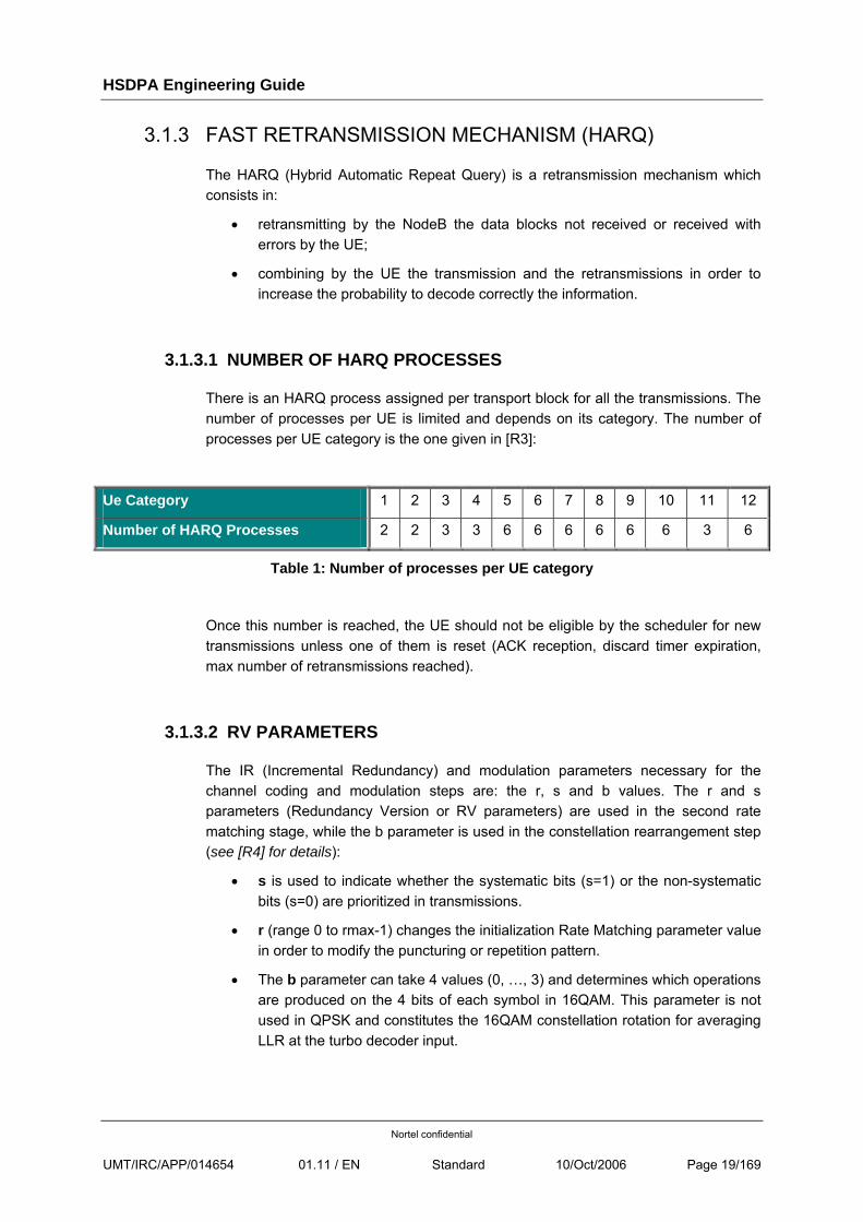
There is an HARQ process assigned per transport block for all the transmissions. The number of processes per UE is limited and depends on its category. The number of processes per UE category is the one given in [R3]:
Ue Category 1 2 3 4 5 6 7 8 9 10 11 12
Number of HARQ Processes 2 2 3 3 6 6 6 6 6 6 3 6
Table 1: Number of processes per UE category
Once this number is reached, the UE should not be eligible by the scheduler for new transmissions unless one of them is reset (ACK reception, discard timer expiration, max number of retransmissions reached).
3.1.3.2 RV PARAMETERS
The IR (Incremental Redundancy) and modulation parameters necessary for the channel coding and modulation steps are: the r, s and b values. The r and s parameters (Redundancy Version or RV parameters) are used in the second rate matching stage, while the b parameter is used in the constellation rearrangement step (see [R4] for details):
• s is used to indicate whether the systematic bits (s=1) or the non-systematic bits (s=0) are prioritized in transmissions.
• r (range 0 to rmax-1) changes the initialization Rate Matching parameter value in order to modify the puncturing or repetition pattern.
• The b parameter can take 4 values (0, …, 3) and determines which operations are produced on the 4 bits of each symbol in 16QAM. This parameter is not used in QPSK and constitutes the 16QAM constellation rotation for averaging LLR at the turbo decoder input.
HSDPA Engineering Guide
Nortel confidential
UMT/IRC/APP/014654 01.11 / EN Standard 10/Oct/2006 Page 20/169
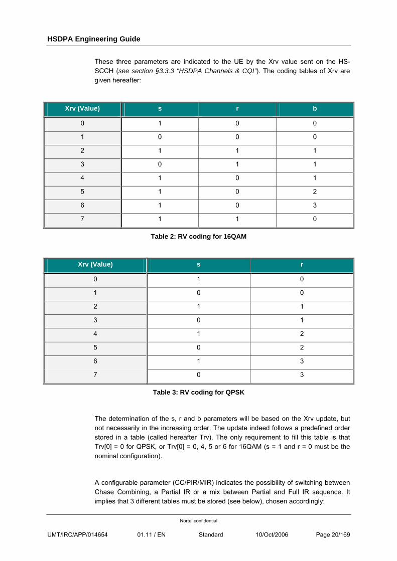
These three parameters are indicated to the UE by the Xrv value sent on the HS-SCCH (see section §3.3.3 "HSDPA Channels & CQI”). The coding tables of Xrv are given hereafter:
Xrv (Value) s r b
0 1 0 0
1 0 0 0
2 1 1 1
3 0 1 1
4 1 0 1
5 1 0 2
6 1 0 3
7 1 1 0
Table 2: RV coding for 16QAM
Xrv (Value) s r
0 1 0
1 0 0
2 1 1
3 0 1
4 1 2
5 0 2
6 1 3
7 0 3
Table 3: RV coding for QPSK
The determination of the s, r and b parameters will be based on the Xrv update, but not necessarily in the increasing order. The update indeed follows a predefined order stored in a table (called hereafter Trv). The only requirement to fill this table is that Trv[0] = 0 for QPSK, or Trv[0] = 0, 4, 5 or 6 for 16QAM (s = 1 and r = 0 must be the nominal configuration).
A configurable parameter (CC/PIR/MIR) indicates the possibility of switching between Chase Combining, a Partial IR or a mix between Partial and Full IR sequence. It implies that 3 different tables must be stored (see below), chosen accordingly:
HSDPA Engineering Guide
Nortel confidential
UMT/IRC/APP/014654 01.11 / EN Standard 10/Oct/2006 Page 21/169
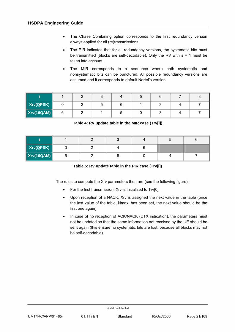
• The Chase Combining option corresponds to the first redundancy version always applied for all (re)transmissions.
• The PIR indicates that for all redundancy versions, the systematic bits must be transmitted (blocks are self-decodable). Only the RV with s = 1 must be taken into account.
• The MIR corresponds to a sequence where both systematic and nonsystematic bits can be punctured. All possible redundancy versions are assumed and it corresponds to default Nortel’s version.
i 1 2 3 4 5 6 7 8
Xrv(QPSK) 0 2 5 6 1 3 4 7
Xrv(16QAM) 6 2 1 5 0 3 4 7
Table 4: RV update table in the MIR case (Trv[i])
i 1 2 3 4 5 6
Xrv(QPSK) 0 2 4 6
Xrv(16QAM) 6 2 5 0 4 7
Table 5: RV update table in the PIR case (Trv[i])
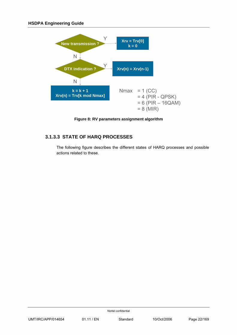
The rules to compute the Xrv parameters then are (see the following figure):
• For the first transmission, Xrv is initialized to Trv[0].
• Upon reception of a NACK, Xrv is assigned the next value in the table (once the last value of the table, Nmax, has been set, the next value should be the first one again).
• In case of no reception of ACK/NACK (DTX indication), the parameters must not be updated so that the same information not received by the UE should be sent again (this ensure no systematic bits are lost, because all blocks may not be self-decodable).
HSDPA Engineering Guide
Nortel confidential
UMT/IRC/APP/014654 01.11 / EN Standard 10/Oct/2006 Page 22/169
New transmission ? Xrv = Trv[0]k = 0
Y
N
DTX indication ? Xrv(n) = Xrv(n-1)Y
N
k = k + 1Xrv(n) = Trv[k mod Nmax]
Nmax = 1 (CC)= 4 (PIR - QPSK)= 6 (PIR – 16QAM)= 8 (MIR)
Figure 8: RV parameters assignment algorithm
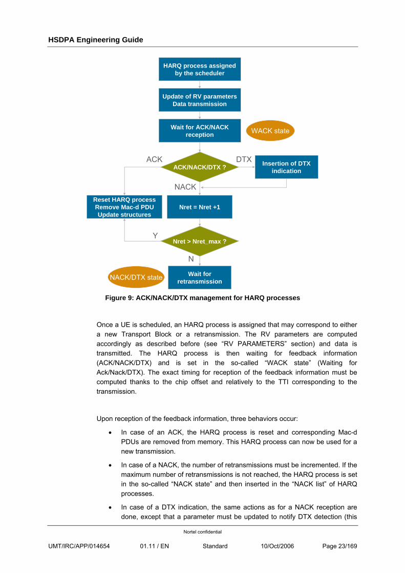
3.1.3.3 STATE OF HARQ PROCESSES
The following figure describes the different states of HARQ processes and possible actions related to these.
HSDPA Engineering Guide
Nortel confidential
UMT/IRC/APP/014654 01.11 / EN Standard 10/Oct/2006 Page 23/169
ACK/NACK/DTX ?
HARQ process assignedby the scheduler
Y
Update of RV parametersData transmission
Wait for ACK/NACK reception
Insertion of DTX indication
Reset HARQ processRemove Mac-d PDUUpdate structures
Nret = Nret +1
Nret > Nret_max ?
Wait for retransmission
NACK
DTX
N
WACK state
NACK/DTX state
ACK
Figure 9: ACK/NACK/DTX management for HARQ processes
Once a UE is scheduled, an HARQ process is assigned that may correspond to either a new Transport Block or a retransmission. The RV parameters are computed accordingly as described before (see “RV PARAMETERS” section) and data is transmitted. The HARQ process is then waiting for feedback information (ACK/NACK/DTX) and is set in the so-called “WACK state” (Waiting for Ack/Nack/DTX). The exact timing for reception of the feedback information must be computed thanks to the chip offset and relatively to the TTI corresponding to the transmission.
Upon reception of the feedback information, three behaviors occur:
• In case of an ACK, the HARQ process is reset and corresponding Mac-d PDUs are removed from memory. This HARQ process can now be used for a new transmission.
• In case of a NACK, the number of retransmissions must be incremented. If the maximum number of retransmissions is not reached, the HARQ process is set in the so-called “NACK state” and then inserted in the “NACK list” of HARQ processes.
• In case of a DTX indication, the same actions as for a NACK reception are done, except that a parameter must be updated to notify DTX detection (this
HSDPA Engineering Guide
Nortel confidential
UMT/IRC/APP/014654 01.11 / EN Standard 10/Oct/2006 Page 24/169
changes the RV parameter update, see “RV PARAMETERS” section). The process is then set in the “DTX state”.
The processes in the NACK or DTX state are just waiting for being re-scheduled for a new retransmission.
3.1.4 FAST SCHEDULING
3.1.4.1 PRINCIPLES
The aim of the Mac-hs scheduler is to optimize the radio resources occupancy between users. Every TTI, it must then select Queue IDs for which data is going to be transmitted and the amount of corresponding Mac-d PDUs to transmit.
The scheduler first receives as input every TTI the number of codes available and the remaining power for HS-PDSCH and HS-SCCH (see “POWER MANAGEMENT” section). The received ACK/NACK and CQI must also be provided to the scheduler when available. Thanks to this information, UE capabilities, configuration parameters provided by the RNC and taking into account the previously scheduled data, the scheduler can select the subflows of the users to schedule in order to optimally use available resources. The main concepts of the scheduler are:
• Retransmissions are of higher priority than new transmissions and should be scheduled first.
• Users with higher priority (CmCH-PI) and better CQI are favoured and get most part of the bandwidth.
• The transport blocks should always be optimized according to the transmitted CQI when possible (if enough codes and power are available and if there’s no CPU limitation).
• No queue ID should be left starving, i.e. the scheduler should always allocate even a small part of radio resources to all users (even those with low priority and bad CQI).
3.1.4.2 ALGORITHM
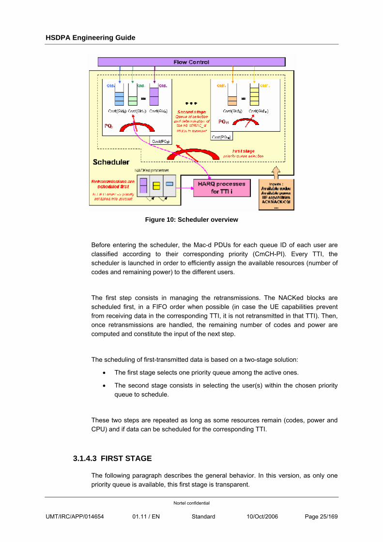
The architecture of the scheduler is presented hereafter (see [R7] for more details on the algorithm):
HSDPA Engineering Guide
Nortel confidential
UMT/IRC/APP/014654 01.11 / EN Standard 10/Oct/2006 Page 25/169
Figure 10: Scheduler overview
Before entering the scheduler, the Mac-d PDUs for each queue ID of each user are classified according to their corresponding priority (CmCH-PI). Every TTI, the scheduler is launched in order to efficiently assign the available resources (number of codes and remaining power) to the different users.
The first step consists in managing the retransmissions. The NACKed blocks are scheduled first, in a FIFO order when possible (in case the UE capabilities prevent from receiving data in the corresponding TTI, it is not retransmitted in that TTI). Then, once retransmissions are handled, the remaining number of codes and power are computed and constitute the input of the next step.
The scheduling of first-transmitted data is based on a two-stage solution:
• The first stage selects one priority queue among the active ones.
• The second stage consists in selecting the user(s) within the chosen priority queue to schedule.
These two steps are repeated as long as some resources remain (codes, power and CPU) and if data can be scheduled for the corresponding TTI.
3.1.4.3 FIRST STAGE
The following paragraph describes the general behavior. In this version, as only one priority queue is available, this first stage is transparent.
HSDPA Engineering Guide
Nortel confidential
UMT/IRC/APP/014654 01.11 / EN Standard 10/Oct/2006 Page 26/169
The selection of a priority queue is based on a cost function that takes into account credits assigned to each priority queue and the number of Mac-d PDUs already transmitted in the last TTI for these queues. The aim is to provide some throughput per queue according to its priority: the higher the priority, the higher the allocated bandwidth.
The credits per queue then depend on their respective priority, on the number of active priority queues but shall also be proportional to the number of active QIDs per priority queue (in order to ensure the bandwidth of high priority QIDs remains more important that low priority ones independently on the number of UEs per priority queue).
The credits per priority queues are recomputed any time the status of a priority queue changes (active/inactive) or if the number of active QIDs in a queue changes. When credits are recomputed, the ratio between queues initially setup is kept.
3.1.4.4 SECOND STAGE
Once a priority queue has been selected, one or more users within that queue are scheduled. The selection of one QID is done according to another cost function that takes into account the processed CQI (noted CQIprocessed in “CQI” section) and the number of Mac-d PDUs transmitted in the last TTI. This ensures that all users are selected but that the bandwidth allocated to the priority queue is separated between users according to their CQI (the higher the CQI, the higher the available throughput).
A user can only be considered as candidate if it is allowed to receive some data in the current TTI, i.e. if several criteria are respected (CQIprocessed ≠ 0, min inter TTI distance, AckNack repetition factor, one HARQ process available, UE not already scheduled for retransmissions).
For each candidate user, HS-SCCH power is determined (see “POWER MANAGEMENT” section) and power checking is done on both the current TTI and the previous one (HS-SCCH and corresponding HS-PDSCH only overlap by 1 slot). If there is not enough power to transmit the HS-SCCH in the current TTI, the user is not selected.
Then for the UE with the lowest cost within the remaining candidates UEs, the number of PDU to transmit as well as the number of codes and the transmitted power are chosen according to the processed CQI in order to fit as well as possible to what the UE can correctly receive (see “POWER MANAGEMENT” section for more details on the algorithm):
HSDPA Engineering Guide
Nortel confidential
UMT/IRC/APP/014654 01.11 / EN Standard 10/Oct/2006 Page 27/169
• If there doesn’t remain enough power to transmit the HS-PDSCH, another configuration requiring less power is selected if possible (transport block size reduced, corresponding to a smaller CQI referred as CQIapplied in Section §6.4 “Power Management”.
• If there doesn’t remain enough codes to transmit the HS-PDSCH, the configuration is changed (transport block size reduced, corresponding to a smaller CQI) to use the remaining codes. The power is then updated accordingly.
Anytime a UE is scheduled, its cost is recomputed according to the transmitted number of MAC-d PDUs.
Another priority queue must be selected when no more QID in the current priority queue can be scheduled (all HARQ processes used for the corresponding UE, min inter TTI distance not compliant with that TTI, no other QID). As only one priority queue is available in this version, the first stage is not recalled and the TTI processing is considered as complete.
The cost of each QID of the selected priority queue is updated anytime another queue must be selected (according to previous criteria) or at the end of a TTI (no more HS-SCCH/HS-PDSCH code, power or CPU).
HSDPA Engineering Guide
Nortel confidential
UMT/IRC/APP/014654 01.11 / EN Standard 10/Oct/2006 Page 28/169
3.2 DEPLOYEMENT SCENARIOS
3.2.1 DUAL CARRIER
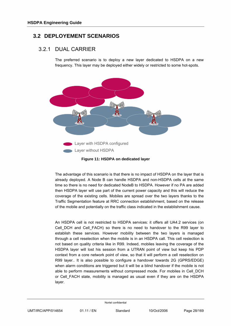
The preferred scenario is to deploy a new layer dedicated to HSDPA on a new frequency. This layer may be deployed either widely or restricted to some hot-spots.
Layer with HSDPA configured
Layer without HSDPA
Figure 11: HSDPA on dedicated layer
The advantage of this scenario is that there is no impact of HSDPA on the layer that is already deployed. A Node B can handle HSDPA and non-HSDPA cells at the same time so there is no need for dedicated NodeB to HSDPA. However if no PA are added then HSDPA layer will use part of the current power capacity and this will reduce the coverage of the existing cells. Mobiles are spread over the two layers thanks to the Traffic Segmentation feature at RRC connection establishment, based on the release of the mobile and potentially on the traffic class indicated in the establishment cause.
An HSDPA cell is not restricted to HSDPA services: it offers all UA4.2 services (on Cell_DCH and Cell_FACH) so there is no need to handover to the R99 layer to establish these services. However mobility between the two layers is managed through a cell reselection when the mobile is in an HSDPA call. This cell reslection is not based on quality criteria like in R99. Indeed, mobiles leaving the coverage of the HSDPA layer will lost his session from a UTRAN point of view but keep his PDP context from a core network point of view, so that it will perform a cell reselection on R99 layer.. It is also possible to configure a handover towards 2G (GPRS/EDGE) when alarm conditions are triggered but it will be a blind handover if the mobile is not able to perform measurements without compressed mode. For mobiles in Cell_DCH or Cell_FACH state, mobility is managed as usual even if they are on the HSDPA layer.
HSDPA Engineering Guide
Nortel confidential
UMT/IRC/APP/014654 01.11 / EN Standard 10/Oct/2006 Page 29/169
Another possible scenario is to deploy HSDPA on a separate cluster (managed or not by a dedicated RNC) but in this case Traffic Segmentation cannot be used as it assumes a twin-cell topology (see 3.5.1 for more details on Traffic Segmentation).
3.2.2 SINGLE CARRIER
Even though deploying HSDPA on a separate layer is the preferred option, HSDPA can be configured on any cell and shared his resources with R99. The drawback of this scenario is that HSDPA traffic may impact R99 traffic by generating high interferences and may need to re-engineer the layer. If HSDPA is not deployed everywhere in the layer then an automatic channel type switching between DCH and HSDPA is performed when the UE enters in or leaves an HSDPA cell.
3.3 HSDPA RESOURCES
3.3.1 OVSF CODES
3.3.1.1 CELL CONFIGURATION
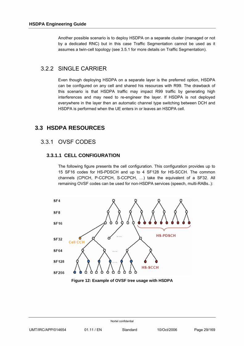
The following figure presents the cell configuration. This configuration provides up to 15 SF16 codes for HS-PDSCH and up to 4 SF128 for HS-SCCH. The common channels (CPICH, P-CCPCH, S-CCPCH, …) take the equivalent of a SF32. All remaining OVSF codes can be used for non-HSDPA services (speech, multi-RABs..):
Figure 12: Example of OVSF tree usage with HSDPA
HSDPA Engineering Guide
Nortel confidential
UMT/IRC/APP/014654 01.11 / EN Standard 10/Oct/2006 Page 30/169
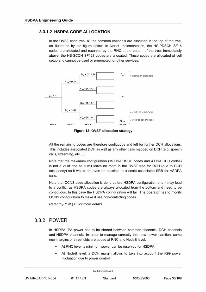
3.3.1.2 HSDPA CODE ALLOCATION
In the OVSF code tree, all the common channels are allocated in the top of the tree, as illustrated by the figure below. In Nortel implementation, the HS-PDSCH SF16 codes are allocated and reserved by the RNC at the bottom of the tree. Immediately above, the HS-SCCH SF128 codes are allocated. These codes are allocated at cell setup and cannot be used or preempted for other services.
SF = nSF = 4SF = 2SF = 1Cn,n-1
…
Cn,0
C4,3 = (1,-1,-1,1)
C2,1 = (1,-1)
C4,2 = (1,-1,1,-1)
C1,0 = (1)
C4,1 = (1,1,-1,-1)
C2,0 = (1,1)
C4,0 = (1,1,1,1)
SF = nSF = 4SF = 2SF = 1Cn,n-1
…
Cn,0
C4,3 = (1,-1,-1,1)
C2,1 = (1,-1)
C4,2 = (1,-1,1,-1)
C1,0 = (1)
C4,1 = (1,1,-1,-1)
C2,0 = (1,1)
C4,0 = (1,1,1,1) Common channels
n SF128 HS-SCCH
m SF16 HS-PDSCH
Figure 13: OVSF allocation strategy
All the remaining codes are therefore contiguous and left for further DCH allocations. This includes associated DCH as well as any other calls mapped on DCH (e.g. speech calls, streaming, etc…).
Note that the maximum configuration (15 HS-PDSCH codes and 4 HS-SCCH codes) is not a valid one as it will leave no room in the OVSF tree for DCH (due to CCH occupancy) so it would not even be possible to allocate associated SRB for HSDPA calls.
Note that OCNS code allocation is done before HSDPA configuration and it may lead to a conflict as HSDPA codes are always allocated from the bottom and need to be contiguous. In this case the HSDPA configuration will fail. The operator has to modify OCNS configuration to make it use non-conflicting codes.
Refer to [R14] §15 for more details.
3.3.2 POWER
In HSDPA, PA power has to be shared between common channels, DCH channels and HSDPA channels. In order to manage correctly this new power partition, some new margins or thresholds are added at RNC and NodeB level:
• At RNC level, a minimum power can be reserved for HSDPA.
• At NodeB level, a DCH margin allows to take into account the R99 power fluctuation due to power control.
HSDPA Engineering Guide
Nortel confidential
UMT/IRC/APP/014654 01.11 / EN Standard 10/Oct/2006 Page 31/169
For more details, see section §6.4 “Power Management”.
3.3.3 HSDPA CHANNELS & CQI
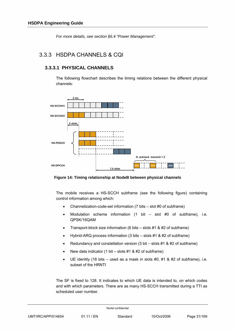
3.3.3.1 PHYSICAL CHANNELS
The following flowchart describes the timing relations between the different physical channels:
HS-SCCH#2
ACK ACK ACK7,5 slots
HS-SCCH#1
HS-PDSCH
N_acknack_transmit = 2
2 ms
HS-DPCCH
2 slots
Figure 14: Timing relationship at NodeB between physical channels
The mobile receives a HS-SCCH subframe (see the following figure) containing control information among which:
• Channelization-code-set information (7 bits – slot #0 of subframe)
• Modulation scheme information (1 bit – slot #0 of subframe), i.e. QPSK/16QAM
• Transport-block size information (6 bits – slots #1 & #2 of subframe)
• Hybrid-ARQ process information (3 bits – slots #1 & #2 of subframe)
• Redundancy and constellation version (3 bit – slots #1 & #2 of subframe)
• New data indicator (1 bit – slots #1 & #2 of subframe)
• UE identity (16 bits – used as a mask in slots #0, #1 & #2 of subframe), i.e. subset of the HRNTI
The SF is fixed to 128. It indicates to which UE data is intended to, on which codes and with which parameters. There are as many HS-SCCH transmitted during a TTI as scheduled user number.
HSDPA Engineering Guide
Nortel confidential
UMT/IRC/APP/014654 01.11 / EN Standard 10/Oct/2006 Page 32/169
Data
Slot #0 Slot #1 Slot #2
1 HS-SCCH subframe = 2ms
Tslot = 2560 chips = 40 bits
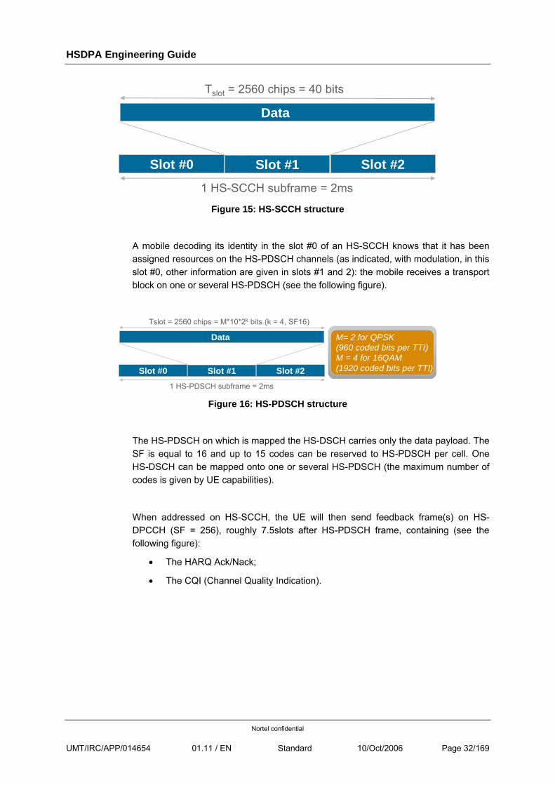
Figure 15: HS-SCCH structure
A mobile decoding its identity in the slot #0 of an HS-SCCH knows that it has been assigned resources on the HS-PDSCH channels (as indicated, with modulation, in this slot #0, other information are given in slots #1 and 2): the mobile receives a transport block on one or several HS-PDSCH (see the following figure).
M= 2 for QPSK (960 coded bits per TTI)M = 4 for 16QAM (1920 coded bits per TTI)
Data
Slot #0 Slot #1 Slot #2
1 HS-PDSCH subframe = 2ms
Tslot = 2560 chips = M*10*2k bits (k = 4, SF16)
Figure 16: HS-PDSCH structure
The HS-PDSCH on which is mapped the HS-DSCH carries only the data payload. The SF is equal to 16 and up to 15 codes can be reserved to HS-PDSCH per cell. One HS-DSCH can be mapped onto one or several HS-PDSCH (the maximum number of codes is given by UE capabilities).
When addressed on HS-SCCH, the UE will then send feedback frame(s) on HS-DPCCH (SF = 256), roughly 7.5slots after HS-PDSCH frame, containing (see the following figure):
• The HARQ Ack/Nack;
• The CQI (Channel Quality Indication).
HSDPA Engineering Guide
Nortel confidential
UMT/IRC/APP/014654 01.11 / EN Standard 10/Oct/2006 Page 33/169
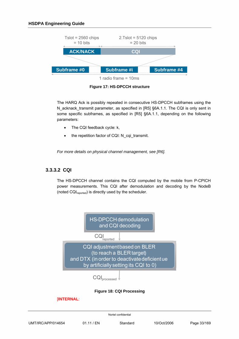
CQI
Subframe #0 Subframe #i Subframe #4
1 radio frame = 10ms
Tslot = 2560 chips = 10 bits
ACK/NACK
2.Tslot = 5120 chips = 20 bits
Figure 17: HS-DPCCH structure
The HARQ Ack is possibly repeated in consecutive HS-DPCCH subframes using the N_acknack_transmit parameter, as specified in [R5] §6A.1.1. The CQI is only sent in some specific subframes, as specified in [R5] §6A.1.1, depending on the following parameters:
• The CQI feedback cycle: k,
• the repetition factor of CQI: N_cqi_transmit.
For more details on physical channel management, see [R6].
3.3.3.2 CQI
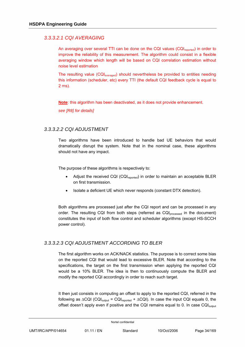
The HS-DPCCH channel contains the CQI computed by the mobile from P-CPICH power measurements. This CQI after demodulation and decoding by the NodeB (noted CQIreported) is directly used by the scheduler.
Figure 18: CQI Processing
[INTERNAL:
HS- DPCCH demodulationand CQI decoding
CQI adjustmentbased on BLER (to reach a BLER target)
and DTX (in order to deactivatedeficientueby artificiallysetting its CQI to 0)
reportedCQI
CQIprocessed
HSDPA Engineering Guide
Nortel confidential
UMT/IRC/APP/014654 01.11 / EN Standard 10/Oct/2006 Page 34/169
3.3.3.2.1 CQI AVERAGING
An averaging over several TTI can be done on the CQI values (CQIreported) in order to improve the reliability of this measurement. The algorithm could consist in a flexible averaging window which length will be based on CQI correlation estimation without noise level estimation
The resulting value (CQIaveraged) should nevertheless be provided to entities needing this information (scheduler, etc) every TTI (the default CQI feedback cycle is equal to 2 ms).
Note: this algorithm has been deactivated, as it does not provide enhancement.
see [R8] for details]
3.3.3.2.2 CQI ADJUSTMENT
Two algorithms have been introduced to handle bad UE behaviors that would dramatically disrupt the system. Note that in the nominal case, these algorithms should not have any impact.
The purpose of these algorithms is respectively to:
• Adjust the received CQI (CQIreported) in order to maintain an acceptable BLER on first transmission.
• Isolate a deficient UE which never responds (constant DTX detection).
Both algorithms are processed just after the CQI report and can be processed in any order. The resulting CQI from both steps (referred as CQIprocessed in the document) constitutes the input of both flow control and scheduler algorithms (except HS-SCCH power control).
3.3.3.2.3 CQI ADJUSTMENT ACCORDING TO BLER
The first algorithm works on ACK/NACK statistics. The purpose is to correct some bias on the reported CQI that would lead to excessive BLER. Note that according to the specifications, the target on the first transmission when applying the reported CQI would be a 10% BLER. The idea is then to continuously compute the BLER and modify the reported CQI accordingly in order to reach such target.
It then just consists in computing an offset to apply to the reported CQI, referred in the following as ∆CQI (CQIoutput = CQIreported + ∆CQI). In case the input CQI equals 0, the offset doesn’t apply even if positive and the CQI remains equal to 0. In case CQIoutput
HSDPA Engineering Guide
Nortel confidential
UMT/IRC/APP/014654 01.11 / EN Standard 10/Oct/2006 Page 35/169
becomes inferior or equal to 0, the UE is not scheduled. In case CQIoutput becomes higher than 30, it is processed as a CQI 30.
It is continuously updated with the following rules:
• A buffer of fixed size (= BufferSize) is created for each UE to compute the BLER.
• Anytime an ACK/NACK is received related to the 1st transmission of a transport block, the buffer is updated to store this information.
o DTX is not taken into account in the buffer.
o The feedback for retransmissions is not either taken into account.
• The buffer is filled in a circular manner (i.e. the new value replaces the oldest one when the buffer is full).
• When at least BufferSize stats have been received (the buffer is full), the number of NACK (NackNb) indication within the last BufferSize ones is computed. The offset is then updated according to the following rules:
o If NackNb ≤ NackNbMin, the system is too good and bandwidth efficiency could be improved (throughput increase and/or power reduction). ∆CQI is increased by 1 and the buffer is reinitialized.
o If NackNb > NackNbmax, the BLER is too high. Performances are then degraded. ∆CQI is decreased by 1 and the buffer is reinitialized.
o In all other cases, the system is considered in its stationary state and then behaves satisfactorily. ∆CQI is not updated and the buffer is not reinitialised.
Note that the buffer is only reinitialized when ∆CQI is updated. This allows waiting for a certain time (BufferSize) before taking a new decision, and thus really evaluating the effect of the new offset value. If the offset has not been updated, the buffer remains filled in a circular manner in order to react as soon as the situation changes (and not wait for a new period before identifying the problem). The offset is bounded and fits in the range [-30.. +30].
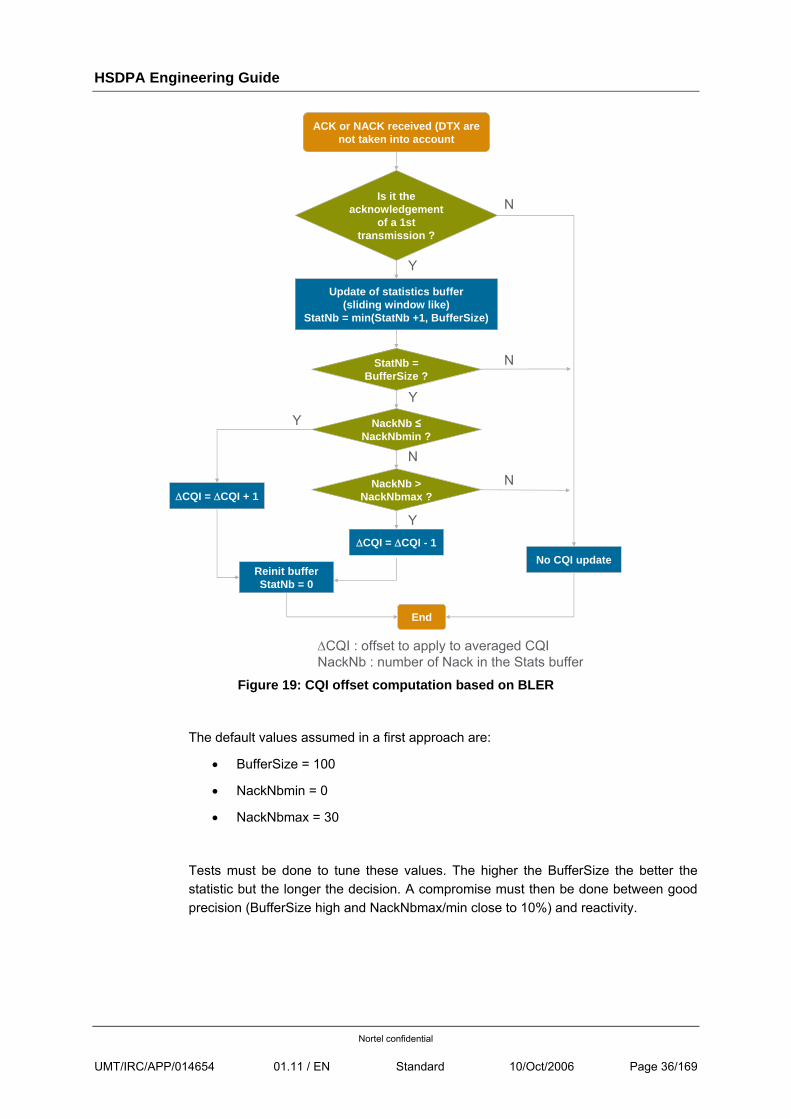
This is illustrated by the following flowchart.
HSDPA Engineering Guide
Nortel confidential
UMT/IRC/APP/014654 01.11 / EN Standard 10/Oct/2006 Page 36/169
ACK or NACK received (DTX are not taken into account
End
Y
Is it theacknowledgement
of a 1st transmission ?
Update of statistics buffer(sliding window like)
StatNb = min(StatNb +1, BufferSize)
N
ΔCQI : offset to apply to averaged CQINackNb : number of Nack in the Stats buffer
StatNb = BufferSize ?
NackNb ≤NackNbmin ?
NackNb >NackNbmax ?ΔCQI = ΔCQI + 1
ΔCQI = ΔCQI - 1No CQI update
Reinit bufferStatNb = 0
N
N
N
Y
Y
Y
Y
Figure 19: CQI offset computation based on BLER
The default values assumed in a first approach are:
• BufferSize = 100
• NackNbmin = 0
• NackNbmax = 30
Tests must be done to tune these values. The higher the BufferSize the better the statistic but the longer the decision. A compromise must then be done between good precision (BufferSize high and NackNbmax/min close to 10%) and reactivity.
HSDPA Engineering Guide
Nortel confidential
UMT/IRC/APP/014654 01.11 / EN Standard 10/Oct/2006 Page 37/169
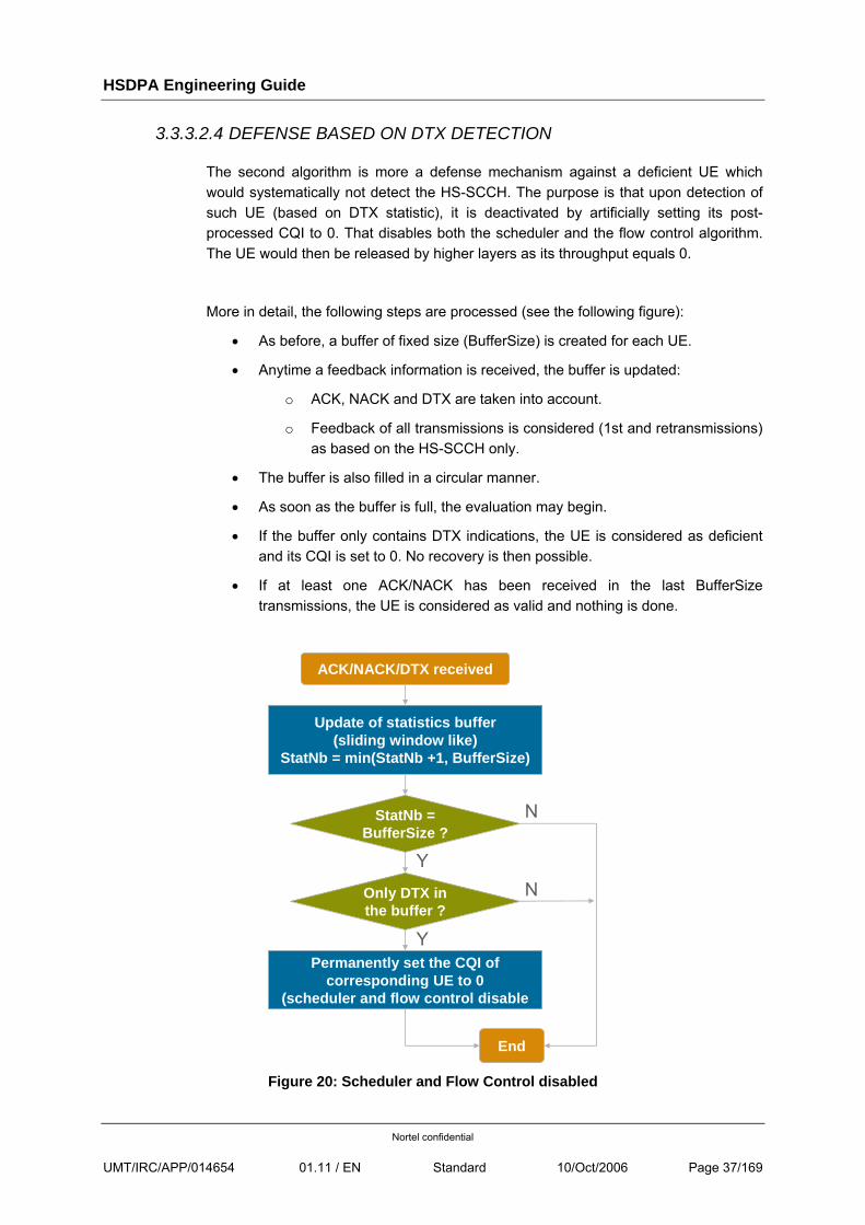
3.3.3.2.4 DEFENSE BASED ON DTX DETECTION
The second algorithm is more a defense mechanism against a deficient UE which would systematically not detect the HS-SCCH. The purpose is that upon detection of such UE (based on DTX statistic), it is deactivated by artificially setting its post-processed CQI to 0. That disables both the scheduler and the flow control algorithm. The UE would then be released by higher layers as its throughput equals 0.
More in detail, the following steps are processed (see the following figure):
• As before, a buffer of fixed size (BufferSize) is created for each UE.
• Anytime a feedback information is received, the buffer is updated:
o ACK, NACK and DTX are taken into account.
o Feedback of all transmissions is considered (1st and retransmissions) as based on the HS-SCCH only.
• The buffer is also filled in a circular manner.
• As soon as the buffer is full, the evaluation may begin.
• If the buffer only contains DTX indications, the UE is considered as deficient and its CQI is set to 0. No recovery is then possible.
• If at least one ACK/NACK has been received in the last BufferSize transmissions, the UE is considered as valid and nothing is done.
ACK/NACK/DTX received
Permanently set the CQI ofcorresponding UE to 0
(scheduler and flow control disable
N
Only DTX in the buffer ?
Y
Update of statistics buffer(sliding window like)
StatNb = min(StatNb +1, BufferSize)
StatNb = BufferSize ?
End
N
Y
Figure 20: Scheduler and Flow Control disabled
HSDPA Engineering Guide
Nortel confidential
UMT/IRC/APP/014654 01.11 / EN Standard 10/Oct/2006 Page 38/169
Default value:
• BufferSize = 100
Note: buffers of both algorithms are independent!
3.4 UE CATEGORIES
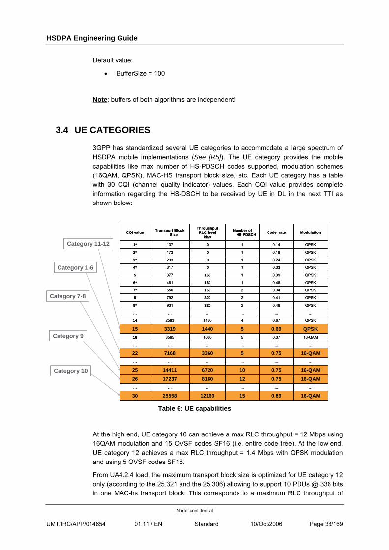
3GPP has standardized several UE categories to accommodate a large spectrum of HSDPA mobile implementations (See [R5]). The UE category provides the mobile capabilities like max number of HS-PDSCH codes supported, modulation schemes (16QAM, QPSK), MAC-HS transport block size, etc. Each UE category has a table with 30 CQI (channel quality indicator) values. Each CQI value provides complete information regarding the HS-DSCH to be received by UE in DL in the next TTI as shown below:
Category 9
Category 10
Category 1-6
Category 11-12
15
...
12
10
...
5
...
5
5
4
...
2
2
2
1
1
1
1
1
1
Number of HS-PDSCH
16-QAM0.89121602555830
…...………
16-QAM0.7581601723726
16-QAM0.7567201441125
…...………
16-QAM0.753360716822
…...………
16-QAM0.371660356516
QPSK0.691440331915
QPSK0.671120258314
…...………
QPSK0.483209319*
QPSK0.413207928
QPSK0.341606507*
QPSK0.481604616*
QPSK0.391603775
QPSK0.3303174*
QPSK0.2402333*
QPSK0.1801732*
QPSK0.1401371*
ModulationCode rateThroughputRLC level
kb/s
Transport Block SizeCQI value
Category 7-8
Table 6: UE capabilities
At the high end, UE category 10 can achieve a max RLC throughput = 12 Mbps using 16QAM modulation and 15 OVSF codes SF16 (i.e. entire code tree). At the low end, UE category 12 achieves a max RLC throughput = 1.4 Mbps with QPSK modulation and using 5 OVSF codes SF16.
From UA4.2.4 load, the maximum transport block size is optimized for UE category 12 only (according to the 25.321 and the 25.306) allowing to support 10 PDUs @ 336 bits in one MAC-hs transport block. This corresponds to a maximum RLC throughput of
HSDPA Engineering Guide
Nortel confidential
UMT/IRC/APP/014654 01.11 / EN Standard 10/Oct/2006 Page 39/169
1.6 Mb/s. This transport block corresponds to a reported CQI equal to 16 and its size is 3440 bits.
3.5 CALL MANAGEMENT
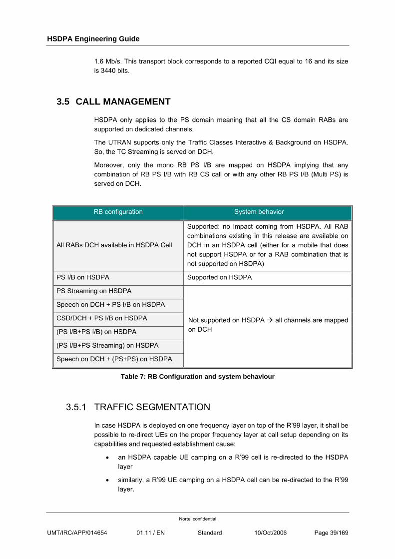
HSDPA only applies to the PS domain meaning that all the CS domain RABs are supported on dedicated channels.
The UTRAN supports only the Traffic Classes Interactive & Background on HSDPA. So, the TC Streaming is served on DCH.
Moreover, only the mono RB PS I/B are mapped on HSDPA implying that any combination of RB PS I/B with RB CS call or with any other RB PS I/B (Multi PS) is served on DCH.
RB configuration System behavior
All RABs DCH available in HSDPA Cell
Supported: no impact coming from HSDPA. All RAB combinations existing in this release are available on DCH in an HSDPA cell (either for a mobile that does not support HSDPA or for a RAB combination that is not supported on HSDPA)
PS I/B on HSDPA Supported on HSDPA
PS Streaming on HSDPA
Speech on DCH + PS I/B on HSDPA
CSD/DCH + PS I/B on HSDPA
(PS I/B+PS I/B) on HSDPA
(PS I/B+PS Streaming) on HSDPA
Speech on DCH + (PS+PS) on HSDPA
Not supported on HSDPA all channels are mapped on DCH
Table 7: RB Configuration and system behaviour
3.5.1 TRAFFIC SEGMENTATION
In case HSDPA is deployed on one frequency layer on top of the R’99 layer, it shall be possible to re-direct UEs on the proper frequency layer at call setup depending on its capabilities and requested establishment cause:
• an HSDPA capable UE camping on a R’99 cell is re-directed to the HSDPA layer
• similarly, a R’99 UE camping on a HSDPA cell can be re-directed to the R’99 layer.
HSDPA Engineering Guide
Nortel confidential
UMT/IRC/APP/014654 01.11 / EN Standard 10/Oct/2006 Page 40/169
This feature impacts the choice of the target cell and the frequency layer at the call establishment.
The main benefits are to allow HSDPA capable mobiles to benefit from HSDPA service and to avoid loading the HSDPA layer with R’99 mobiles.
3.5.1.1 TRAFFIC SEGMENTATION MECHANISM
The redirection is performed by the RNC at the call setup phase based on the twin-cells configuration which is not compatible in this case with the f1/f2 mobility-capacity inter-frequency hard hand over.
No redirection is performed by the RNC during the call – meaning for example that even if a mobile, initially on HSDPA layer, reselects the R’99 layer in AO cell_fach state for traffic resuming, it will be served using the DCH layer.
Emergency calls are never redirected and are served on the layer selected by the mobile to limit the probability of call setup failure.
3.5.1.1.1 TRAFFIC SEGMENTATION CRITERIA:
Two filtering can be operated in order to execute the redirection on the suitable layer:
• First criterion is based on the Access Stratum Release Indication IE in the RRC Connection Request message for the identification of the R99/R4 mobiles versus the R5 mobiles
• Second optional criterion is based on the Establishment Cause IE in the RRC Connection Request message to distinguish the calls I/B potentially served on HSDPA from the others.
This filtering is not necessarily representative of the services setup during the life of the RRC connection (for example the addition of a CS call on top of a hsdpa connection implies the switching of the PS connection on dch channel in the hsdpa layer).
3.5.1.2 TRAFFIC SEGMENTATION PROCEDURE
At the reception of the RRC Connection Request, the RNC identifies:
• the UE Release via the ‘Access Stratum Release indicator IE’ knowing that R’99/R4 mobiles don’t support HSDPA configuration
• the requested service via the ‘Establishment Cause IE’ knowing that traffic class Conversational and Streaming can’t be served on HSDPA. This filtering is optional depending on the setting of the parameter isRedirectionBasedOnEstablishmentCause
HSDPA Engineering Guide
Nortel confidential
UMT/IRC/APP/014654 01.11 / EN Standard 10/Oct/2006 Page 41/169
So, based on the information of Access Stratum Release indicator and Establishment Cause IE, the RNC can start the redirection procedure for the R5 mobiles requesting a PS I/B session.
The redirection consists in indicating the target frequency in the RRC Connection Setup message via the ‘Frequency Info IE’, frequency corresponding to the one of the twin cell.
The UE will send the RRC Connection Setup Complete towards the twin cell on the right layer.
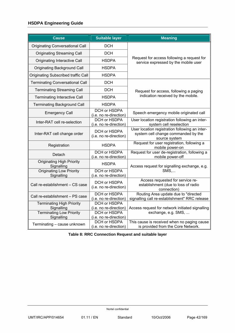
Hereafter the static mapping between the Establishment cause sent by the mobile in the RRC Connection Request and the suitable layer pointed by the RNC :
HSDPA Engineering Guide
Nortel confidential
UMT/IRC/APP/014654 01.11 / EN Standard 10/Oct/2006 Page 42/169
Cause Suitable layer Meaning
Originating Conversational Call DCH
Originating Streaming Call DCH
Originating Interactive Call HSDPA
Originating Background Call HSDPA
Originating Subscribed traffic Call HSDPA
Request for access following a request for service expressed by the mobile user
Terminating Conversational Call DCH
Terminating Streaming Call DCH
Terminating Interactive Call HSDPA
Terminating Background Call HSDPA
Request for access, following a paging indication received by the mobile.
Emergency Call DCH or HSDPA (i.e. no re-direction) Speech emergency mobile originated call
Inter-RAT cell re-selection DCH or HSDPA (i.e. no re-direction)
User location registration following an inter-system cell reselection
Inter-RAT cell change order DCH or HSDPA (i.e. no re-direction)
User location registration following an inter-system cell change commanded by the
source system
Registration HSDPA Request for user registration, following a mobile power-on
Detach DCH or HSDPA (i.e. no re-direction)
Request for user de-registration, following a mobile power-off
Originating High Priority Signalling HSDPA
Originating Low Priority Signalling
DCH or HSDPA (i.e. no re-direction)
Access request for signalling exchange, e.g. SMS,...
Call re-establishment – CS case DCH or HSDPA (i.e. no re-direction)
Access requested for service re-establishment (due to loss of radio
connection)
Call re-establishment – PS case DCH or HSDPA (i.e. no re-direction)
Routing Area update due to "directed signalling call re-establishment" RRC release
Terminating High Priority Signalling
DCH or HSDPA (i.e. no re-direction)
Terminating Low Priority Signalling
DCH or HSDPA (i.e. no re-direction)
Access request for network initiated signalling exchange, e.g. SMS, ...
Terminating – cause unknown DCH or HSDPA (i.e. no re-direction)
This cause is received when no paging cause is provided from the Core Network.
Table 8: RRC Connection Request and suitable layer
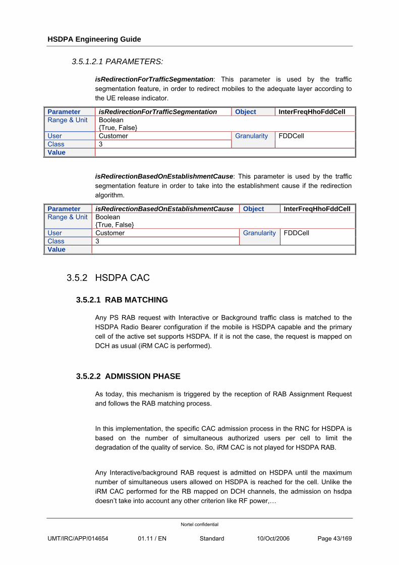
HSDPA Engineering Guide
Nortel confidential
UMT/IRC/APP/014654 01.11 / EN Standard 10/Oct/2006 Page 43/169
3.5.1.2.1 PARAMETERS:
isRedirectionForTrafficSegmentation: This parameter is used by the traffic segmentation feature, in order to redirect mobiles to the adequate layer according to the UE release indicator.
Parameter isRedirectionForTrafficSegmentation Object InterFreqHhoFddCell Range & Unit Boolean
{True, False} User Customer Class 3
Granularity FDDCell
Value
isRedirectionBasedOnEstablishmentCause: This parameter is used by the traffic segmentation feature in order to take into the establishment cause if the redirection algorithm.
Parameter isRedirectionBasedOnEstablishmentCause Object InterFreqHhoFddCell Range & Unit Boolean
{True, False} User Customer Class 3
Granularity FDDCell
Value
3.5.2 HSDPA CAC
3.5.2.1 RAB MATCHING
Any PS RAB request with Interactive or Background traffic class is matched to the HSDPA Radio Bearer configuration if the mobile is HSDPA capable and the primary cell of the active set supports HSDPA. If it is not the case, the request is mapped on DCH as usual (iRM CAC is performed).
3.5.2.2 ADMISSION PHASE
As today, this mechanism is triggered by the reception of RAB Assignment Request and follows the RAB matching process.
In this implementation, the specific CAC admission process in the RNC for HSDPA is based on the number of simultaneous authorized users per cell to limit the degradation of the quality of service. So, iRM CAC is not played for HSDPA RAB.
Any Interactive/background RAB request is admitted on HSDPA until the maximum number of simultaneous users allowed on HSDPA is reached for the cell. Unlike the iRM CAC performed for the RB mapped on DCH channels, the admission on hsdpa doesn’t take into account any other criterion like RF power,…
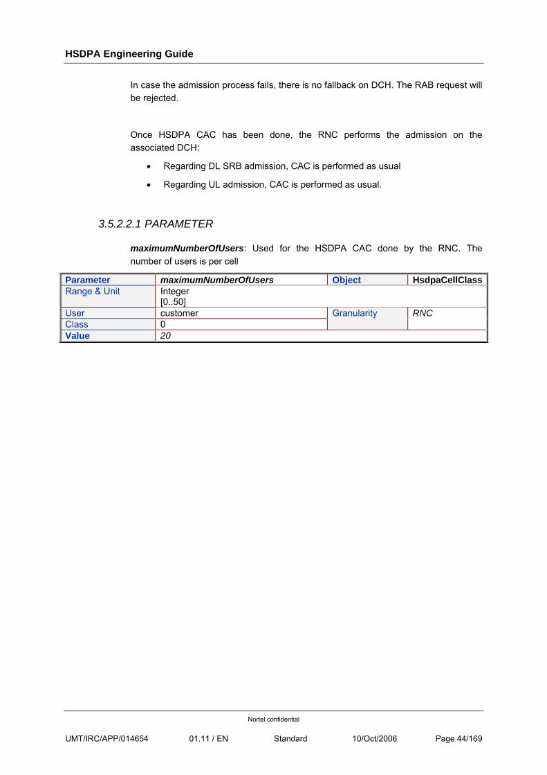
HSDPA Engineering Guide
Nortel confidential
UMT/IRC/APP/014654 01.11 / EN Standard 10/Oct/2006 Page 44/169
In case the admission process fails, there is no fallback on DCH. The RAB request will be rejected.
Once HSDPA CAC has been done, the RNC performs the admission on the associated DCH:
• Regarding DL SRB admission, CAC is performed as usual
• Regarding UL admission, CAC is performed as usual.
3.5.2.2.1 PARAMETER
maximumNumberOfUsers: Used for the HSDPA CAC done by the RNC. The number of users is per cell
Parameter maximumNumberOfUsers Object HsdpaCellClassRange & Unit Integer
[0..50] User customer Class 0
Granularity RNC
Value 20
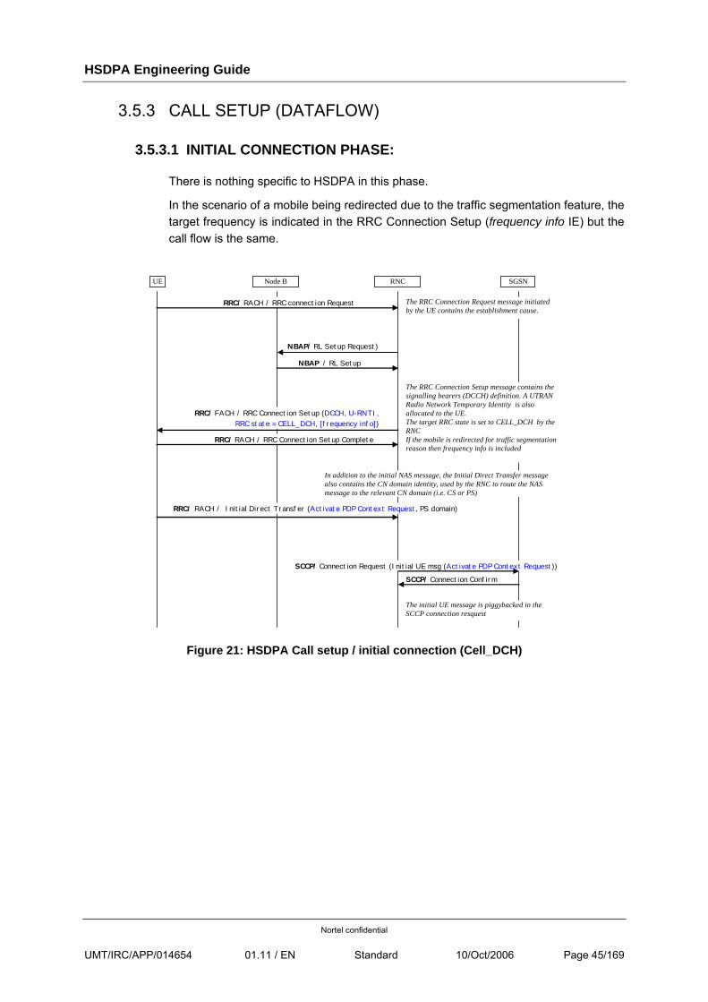
HSDPA Engineering Guide
Nortel confidential
UMT/IRC/APP/014654 01.11 / EN Standard 10/Oct/2006 Page 45/169
3.5.3 CALL SETUP (DATAFLOW)
3.5.3.1 INITIAL CONNECTION PHASE:
There is nothing specific to HSDPA in this phase.
In the scenario of a mobile being redirected due to the traffic segmentation feature, the target frequency is indicated in the RRC Connection Setup (frequency info IE) but the call flow is the same.
SGSN Node B RNC UE
RRC/ RACH / RRC connection Request
SCCP/ Connection Request (Initial UE msg (Activate PDP Context Request))
SCCP/ Connection Confirm
RRC/ FACH / RRC Connection Setup (DCCH, U-RNTI, RRC state = CELL_DCH, [frequency info])
RRC/ RACH / RRC Connection Setup Complete
RRC/ RACH / Initial Direct Transfer (Activate PDP Context Request, PS domain)
The RRC Connection Setup message contains the signalling bearers (DCCH) definition. A UTRAN Radio Network Temporary Identity is also allocated to the UE. The target RRC state is set to CELL_DCH by the RNC If the mobile is redirected for traffic segmentation reason then frequency info is included
In addition to the initial NAS message, the Initial Direct Transfer message also contains the CN domain identity, used by the RNC to route the NAS message to the relevant CN domain (i.e. CS or PS)
The RRC Connection Request message initiated by the UE contains the establishment cause.
The initial UE message is piggybacked in the SCCP connection resquest
NBAP/ RL Setup Request)
NBAP / RL Setup
Figure 21: HSDPA Call setup / initial connection (Cell_DCH)
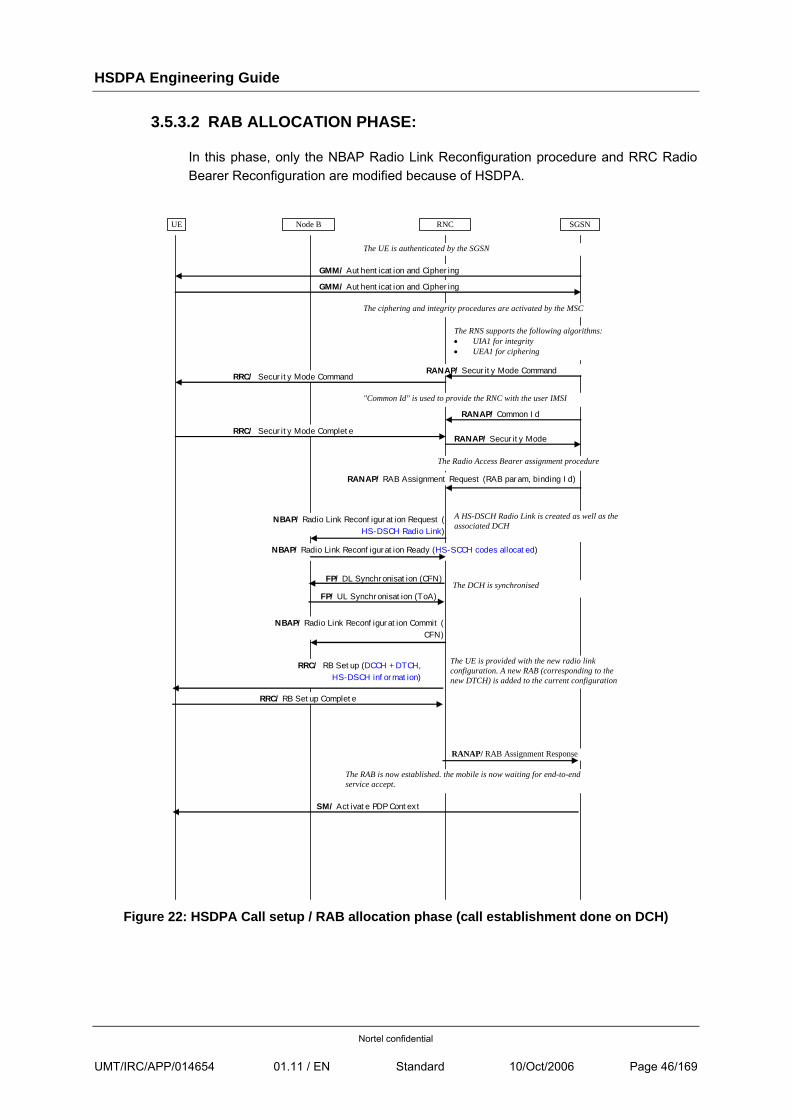
HSDPA Engineering Guide
Nortel confidential
UMT/IRC/APP/014654 01.11 / EN Standard 10/Oct/2006 Page 46/169
3.5.3.2 RAB ALLOCATION PHASE:
In this phase, only the NBAP Radio Link Reconfiguration procedure and RRC Radio Bearer Reconfiguration are modified because of HSDPA.
SGSN Node B RNC UE
SM/ Activate PDP Context
GMM/ Authentication and Ciphering
GMM/ Authentication and Ciphering
The UE is authenticated by the SGSN
RANAP/ Security Mode Command
RANAP/ Security Mode
RRC/ Security Mode Command
RRC/ Security Mode Complete
The ciphering and integrity procedures are activated by the MSC
The RNS supports the following algorithms: • UIA1 for integrity • UEA1 for ciphering
RANAP/ RAB Assignment Response
RANAP/ RAB Assignment Request (RAB param, binding Id)
The Radio Access Bearer assignment procedure
The RAB is now established. the mobile is now waiting for end-to-end service accept.
RRC/ RB Setup (DCCH + DTCH, HS-DSCH information)
RRC/ RB Setup Complete
The UE is provided with the new radio link configuration. A new RAB (corresponding to the new DTCH) is added to the current configuration
NBAP/ Radio Link Reconfiguration Request ( HS-DSCH Radio Link)
NBAP/ Radio Link Reconfiguration Ready (HS-SCCH codes allocated)
A HS-DSCH Radio Link is created as well as the associated DCH
FP/ DL Synchronisation (CFN)
FP/ UL Synchronisation (ToA) The DCH is synchronised
RANAP/ Common Id
"Common Id" is used to provide the RNC with the user IMSI
NBAP/ Radio Link Reconfiguration Commit ( CFN)
Figure 22: HSDPA Call setup / RAB allocation phase (call establishment done on DCH)
HSDPA Engineering Guide
Nortel confidential
UMT/IRC/APP/014654 01.11 / EN Standard 10/Oct/2006 Page 47/169
3.5.4 CALL RELEASE (DATAFLOW)
The call release is initiated either by the mobile or the network through a PDP context de-activation procedure, or by the RNC (Always-On step 2) through Iu Release Request.
Depending on the Core Network implementation, the UTRAN is released, either using an Iu release or a RAB release procedure.
3.5.4.1 IU RELEASE CASE
In such a case, the UTRAN resource release is requested by the Core Network through an Iu Release Command message.
On reception of this message:
• the RRC connection is released
• the HSDPA and associated DCH are released. A Radio Link Deletion request is sent to each of the BTS being part of the active set, including the BTS which supports the HS-DSCH.
3.5.4.2 RAB RELEASE CASE
In such a case the UTRAN resource release is requested by the Core Network through an RAB Assignment Request (cause RAB to release) message.
On reception of this message, as illustrated in the following picture:
• the RNC attempts a Radio Link Reconfiguration to remove the HSDPA MAC-d flow from the cell supporting it and
• a RB Release removes the HSDPA RB.
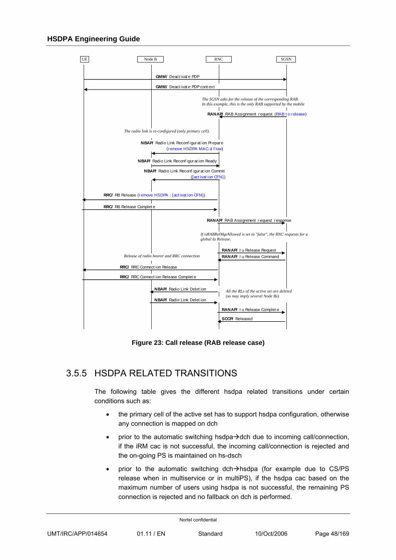
HSDPA Engineering Guide
Nortel confidential
UMT/IRC/APP/014654 01.11 / EN Standard 10/Oct/2006 Page 48/169
SGSN Node B RNC UE
GMM/ Deactivate PDP
GMM/ Deactivate PDP context
The SGSN asks for the release of the corresponding RAB. In this example, this is the only RAB supported by the mobile
RANAP/ RAB Assignment request (RAB to release)
RANAP/ RAB Assignment request response
NBAP/ Radio Link Reconfiguration Prepare (remove HSDPA MAC-d flow)
The radio link is re-configured (only primary cell).
RRC/ RRC Connection Release
NBAP/ Radio Link Deletion
NBAP/ Radio Link Deletion
SCCP/ Released
RANAP/ Iu Release Complete
RANAP/ Iu Release Command
If isRABRelMgtAllowed is set to "false", the RNC requests for a global Iu Release.
RRC/ RRC Connection Release Complete
Release of radio bearer and RRC connectionRANAP/ Iu Release Request
NBAP/ Radio Link Reconfiguration Ready
NBAP/ Radio Link Reconfiguration Commit ([activation CFN])
RRC/ RB Release (remove HSDPA ; [activation CFN])
RRC/ RB Release Complete
All the RLs of the active set are deleted (so may imply several Node Bs)
Figure 23: Call release (RAB release case)
3.5.5 HSDPA RELATED TRANSITIONS
The following table gives the different hsdpa related transitions under certain conditions such as:
• the primary cell of the active set has to support hsdpa configuration, otherwise any connection is mapped on dch
• prior to the automatic switching hsdpa dch due to incoming call/connection, if the iRM cac is not successful, the incoming call/connection is rejected and the on-going PS is maintained on hs-dsch
• prior to the automatic switching dch hsdpa (for example due to CS/PS release when in multiservice or in multiPS), if the hsdpa cac based on the maximum number of users using hsdpa is not successful, the remaining PS connection is rejected and no fallback on dch is performed.
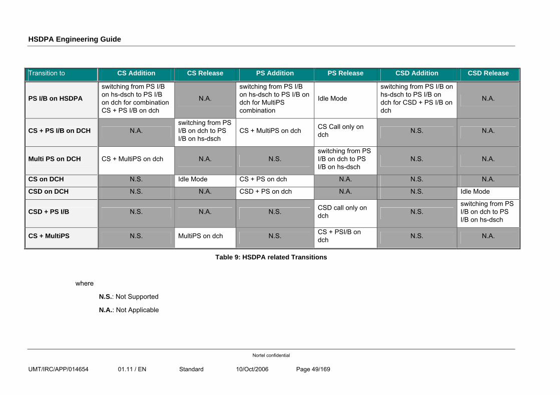
HSDPA Engineering Guide
Nortel confidential
UMT/IRC/APP/014654 01.11 / EN Standard 10/Oct/2006 Page 49/169
Transition to CS Addition CS Release PS Addition PS Release CSD Addition CSD Release
PS I/B on HSDPA
switching from PS I/B on hs-dsch to PS I/B on dch for combination CS + PS I/B on dch
N.A.
switching from PS I/B on hs-dsch to PS I/B on dch for MultiPS combination
Idle Mode
switching from PS I/B on hs-dsch to PS I/B on dch for CSD + PS I/B on dch
N.A.
CS + PS I/B on DCH N.A. switching from PS I/B on dch to PS I/B on hs-dsch
CS + MultiPS on dch CS Call only on dch N.S. N.A.
Multi PS on DCH CS + MultiPS on dch N.A. N.S. switching from PS I/B on dch to PS I/B on hs-dsch
N.S. N.A.
CS on DCH N.S. Idle Mode CS + PS on dch N.A. N.S. N.A.
CSD on DCH N.S. N.A. CSD + PS on dch N.A. N.S. Idle Mode
CSD + PS I/B N.S. N.A. N.S. CSD call only on dch N.S.
switching from PS I/B on dch to PS I/B on hs-dsch
CS + MultiPS N.S. MultiPS on dch N.S. CS + PSI/B on dch N.S. N.A.
Table 9: HSDPA related Transitions
where
N.S.: Not Supported
N.A.: Not Applicable
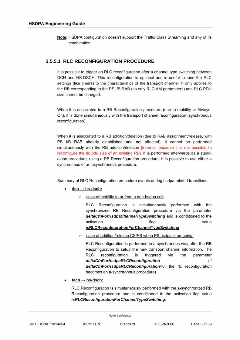
HSDPA Engineering Guide
Nortel confidential
UMT/IRC/APP/014654 01.11 / EN Standard 10/Oct/2006 Page 50/169
Note: HSDPA configuration doesn’t support the Traffic Class Streaming and any of its combination.
3.5.5.1 RLC RECONFIGURATION PROCEDURE
It is possible to trigger an RLC reconfiguration after a channel type switching between DCH and HS-DSCH. This reconfiguration is optional and is useful to tune the RLC settings (like timers) to the characteristics of the transport channel. It only applies to the RB corresponding to the PS I/B RAB (so only RLC AM parameters) and RLC PDU size cannot be changed.
When it is associated to a RB Reconfiguration procedure (due to mobility or Always-On), it is done simultaneously with the transport channel reconfiguration (synchronous reconfiguration).
When it is associated to a RB addition/deletion (due to RAB assignment/release, with PS I/B RAB already established and not affected), it cannot be performed simultaneously with the RB addition/deletion [Internal: because it is not possible to reconfigure the rlc pdu size of an existing RB]. It is performed afterwards as a stand-alone procedure, using a RB Reconfiguration procedure. It is possible to use either a synchronous or an asynchronous procedure.
Summary of RLC Reconfiguration procedure events during hsdpa related transitions:
• dch ↔ hs-dsch:
o case of mobility to or from a non-hsdpa cell:
RLC Reconfiguration is simultaneously performed with the synchronized RB Reconfiguration procedure via the parameter deltaCfnForHsdpaChannelTypeSwitching and is conditioned to the activation flag value isRLCReconfigurationForChannelTypeSwitching
o case of addition/release CS/PS when PS hsdpa is on-going:
RLC Reconfiguration is performed in a synchronous way after the RB Reconfiguration to setup the new transport channel information. The RLC reconfiguration is triggered via the parameter deltaCfnForHsdpaRLCReconfiguration (if deltaCfnForHsdpaRLCReconfiguration=0, the rlc reconfiguration becomes an a-synchronous procedure).
• fach ↔ hs-dsch:
RLC Reconfiguration is simultaneously performed with the a-synchronized RB Reconfiguration procedure and is conditioned to the activation flag value isRLCReconfigurationForChannelTypeSwitching.
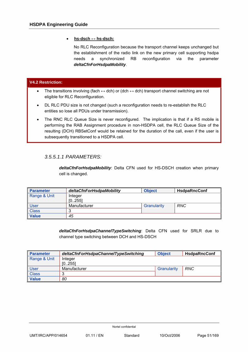
HSDPA Engineering Guide
Nortel confidential
UMT/IRC/APP/014654 01.11 / EN Standard 10/Oct/2006 Page 51/169
• hs-dsch ↔ hs-dsch:
No RLC Reconfiguration because the transport channel keeps unchanged but the establishment of the radio link on the new primary cell supporting hsdpa needs a synchronized RB reconfiguration via the parameter deltaCfnForHsdpaMobility.
V4.2 Restriction:
• The transitions involving (fach ↔ dch) or (dch ↔ dch) transport channel switching are not eligible for RLC Reconfiguration.
• DL RLC PDU size is not changed (such a reconfiguration needs to re-establish the RLC entities so lose all PDUs under transmission).
• The RNC RLC Queue Size is never reconfigured. The implication is that if a R5 mobile is performing the RAB Assignment procedure in non-HSDPA cell, the RLC Queue Size of the resulting (DCH) RBSetConf would be retained for the duration of the call, even if the user is subsequently transitioned to a HSDPA cell.
3.5.5.1.1 PARAMETERS:
deltaCfnForHsdpaMobility: Delta CFN used for HS-DSCH creation when primary cell is changed.
Parameter deltaCfnForHsdpaMobility Object HsdpaRncConf Range & Unit Integer
[0..255] User Manufacturer Class 3
Granularity RNC
Value 45
deltaCfnForHsdpaChannelTypeSwitching: Delta CFN used for SRLR due to channel type switching between DCH and HS-DSCH
Parameter deltaCfnForHsdpaChannelTypeSwitching Object HsdpaRncConf Range & Unit Integer
[0..255] User Manufacturer Class 3
Granularity RNC
Value 80
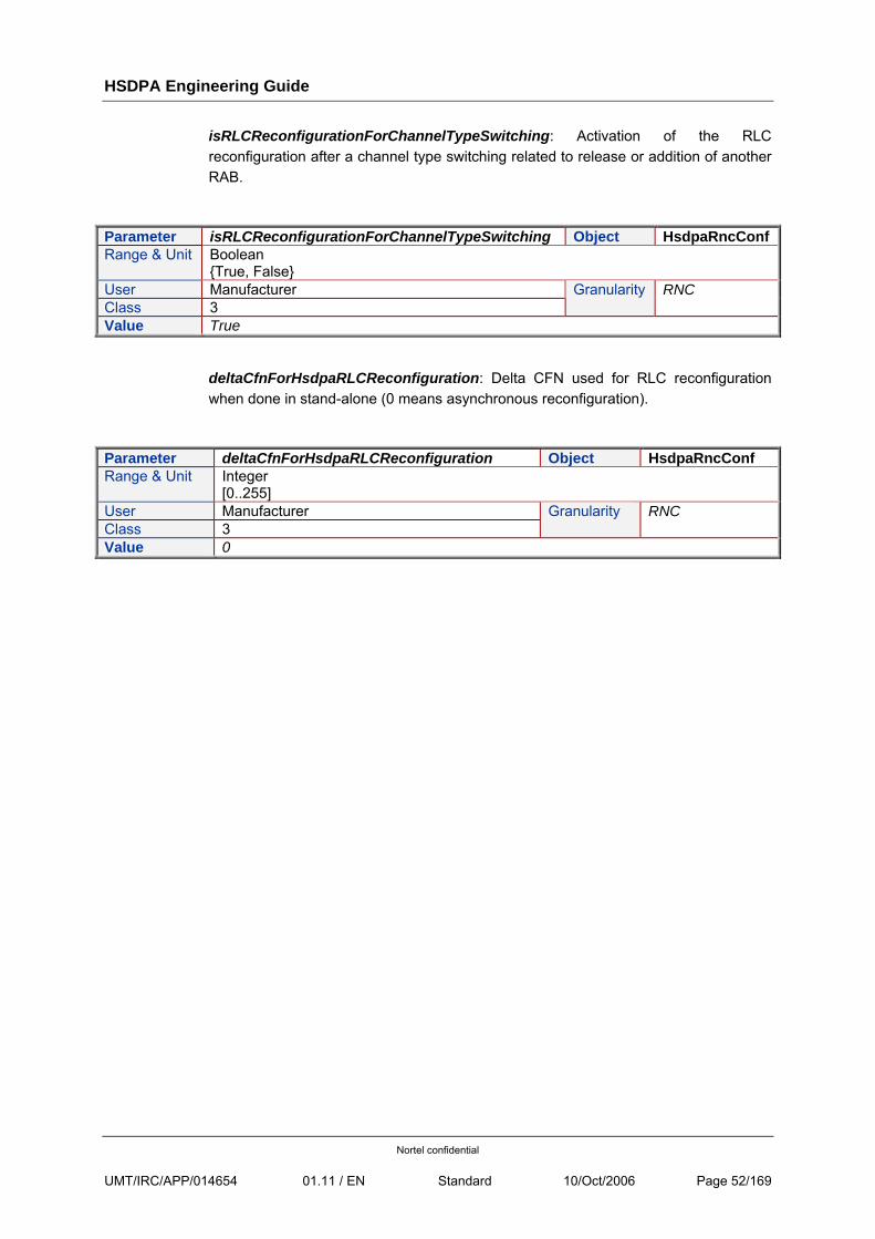
HSDPA Engineering Guide
Nortel confidential
UMT/IRC/APP/014654 01.11 / EN Standard 10/Oct/2006 Page 52/169
isRLCReconfigurationForChannelTypeSwitching: Activation of the RLC reconfiguration after a channel type switching related to release or addition of another RAB.
Parameter isRLCReconfigurationForChannelTypeSwitching Object HsdpaRncConf Range & Unit Boolean
{True, False} User Manufacturer Class 3
Granularity RNC
Value True
deltaCfnForHsdpaRLCReconfiguration: Delta CFN used for RLC reconfiguration when done in stand-alone (0 means asynchronous reconfiguration).
Parameter deltaCfnForHsdpaRLCReconfiguration Object HsdpaRncConf Range & Unit Integer
[0..255] User Manufacturer Class 3
Granularity RNC
Value 0
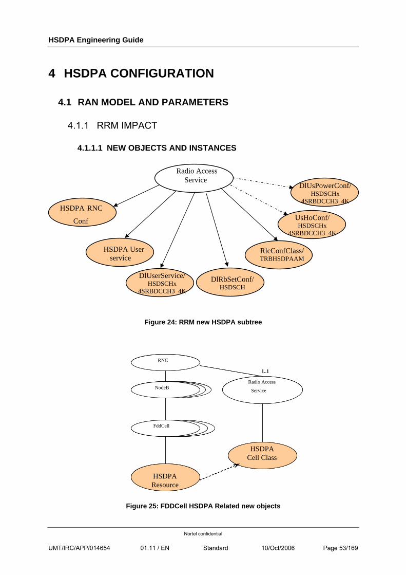
HSDPA Engineering Guide
Nortel confidential
UMT/IRC/APP/014654 01.11 / EN Standard 10/Oct/2006 Page 53/169
4 HSDPA CONFIGURATION
4.1 RAN MODEL AND PARAMETERS
4.1.1 RRM IMPACT
4.1.1.1 NEW OBJECTS AND INSTANCES
Figure 24: RRM new HSDPA subtree
FddCellFddCell
NodeBNodeB
RNC
NodeB
FddCell
HSDPA Resource
Radio Access
Service
HSDPA Cell Class
1..1
FddCellFddCell
NodeBNodeB
RNC
NodeB
FddCell
HSDPA Resource
Radio Access
Service
HSDPA Cell Class
1..1
Figure 25: FDDCell HSDPA Related new objects
Radio Access Service
HSDPA User service
HSDPA RNC
Conf
DlUserService/HSDSCHx
4SRBDCCH3 4K
DlRbSetConf/HSDSCH
RlcConfClass/ TRBHSDPAAM
UsHoConf/ HSDSCHx
4SRBDCCH3 4K
DlUsPowerConf/HSDSCHx
4SRBDCCH3 4K
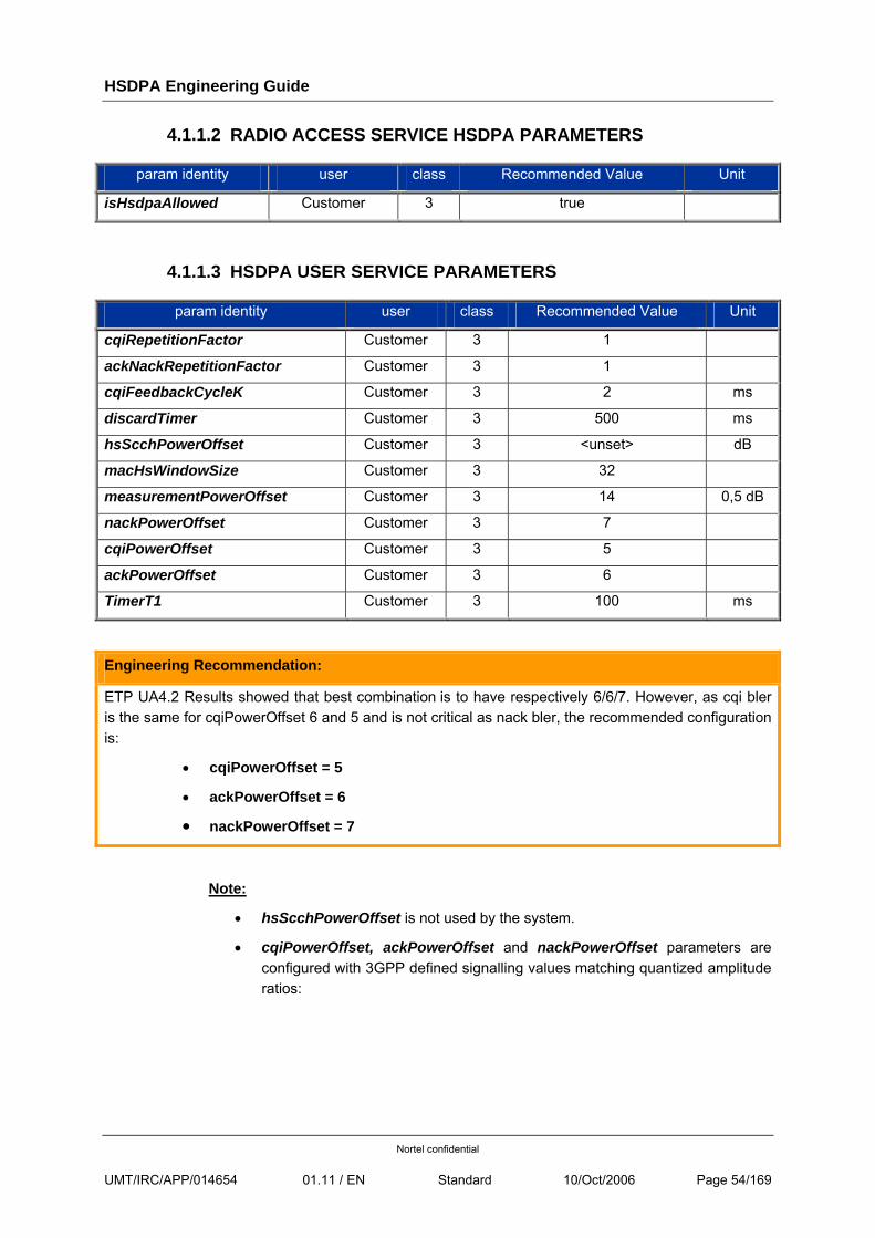
HSDPA Engineering Guide
Nortel confidential
UMT/IRC/APP/014654 01.11 / EN Standard 10/Oct/2006 Page 54/169
4.1.1.2 RADIO ACCESS SERVICE HSDPA PARAMETERS
param identity user class Recommended Value Unit
isHsdpaAllowed Customer 3 true
4.1.1.3 HSDPA USER SERVICE PARAMETERS
param identity user class Recommended Value Unit
cqiRepetitionFactor Customer 3 1
ackNackRepetitionFactor Customer 3 1
cqiFeedbackCycleK Customer 3 2 ms
discardTimer Customer 3 500 ms
hsScchPowerOffset Customer 3 <unset> dB
macHsWindowSize Customer 3 32
measurementPowerOffset Customer 3 14 0,5 dB
nackPowerOffset Customer 3 7
cqiPowerOffset Customer 3 5
ackPowerOffset Customer 3 6
TimerT1 Customer 3 100 ms
Engineering Recommendation:
ETP UA4.2 Results showed that best combination is to have respectively 6/6/7. However, as cqi bler is the same for cqiPowerOffset 6 and 5 and is not critical as nack bler, the recommended configuration is:
• cqiPowerOffset = 5
• ackPowerOffset = 6
• nackPowerOffset = 7
Note:
• hsScchPowerOffset is not used by the system.
• cqiPowerOffset, ackPowerOffset and nackPowerOffset parameters are configured with 3GPP defined signalling values matching quantized amplitude ratios:
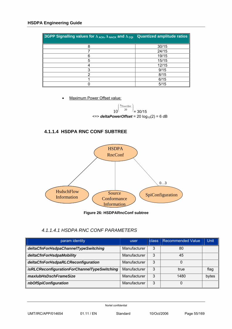
HSDPA Engineering Guide
Nortel confidential
UMT/IRC/APP/014654 01.11 / EN Standard 10/Oct/2006 Page 55/169
3GPP Signalling values for Δ ACK, Δ NACK and Δ CQI Quantized amplitude ratios
8 30/15 7 24/15 6 19/15 5 15/15 4 12/15 3 9/15 2 8/15 1 6/15 0 5/15
• Maximum Power Offset value:
⎟⎟⎠
⎞⎜⎜⎝
⎛ Δ
2010PowerOfset
= 30/15 <=> deltaPowerOffset = 20 log10(2) = 6 dB
4.1.1.4 HSDPA RNC CONF SUBTREE
HSDPA RncConf
HsdschFlowInformation
SourceConformanceInformation
SpiConfiguration
0…3
Figure 26: HSDPARncConf subtree
4.1.1.4.1 HSDPA RNC CONF PARAMETERS
param identity user class Recommended Value Unit
deltaCfnForHsdpaChannelTypeSwitching Manufacturer 3 80
deltaCfnForHsdpaMobility Manufacturer 3 45
deltaCfnForHsdpaRLCReconfiguration Manufacturer 3 0
isRLCReconfigurationForChannelTypeSwitching Manufacturer 3 true flag
maxIubHsDschFrameSize Manufacturer 3 1480 bytes
nbOfSpiConfiguration Manufacturer 3 0
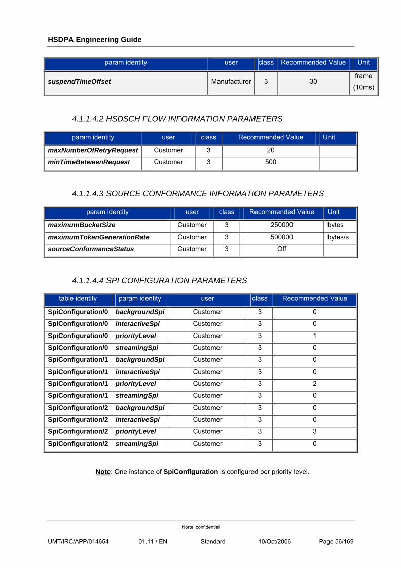
HSDPA Engineering Guide
Nortel confidential
UMT/IRC/APP/014654 01.11 / EN Standard 10/Oct/2006 Page 56/169
param identity user class Recommended Value Unit
suspendTimeOffset Manufacturer 3 30 frame
(10ms)
4.1.1.4.2 HSDSCH FLOW INFORMATION PARAMETERS
param identity user class Recommended Value Unit
maxNumberOfRetryRequest Customer 3 20
minTimeBetweenRequest Customer 3 500
4.1.1.4.3 SOURCE CONFORMANCE INFORMATION PARAMETERS
param identity user class Recommended Value Unit
maximumBucketSize Customer 3 250000 bytes
maximumTokenGenerationRate Customer 3 500000 bytes/s
sourceConformanceStatus Customer 3 Off
4.1.1.4.4 SPI CONFIGURATION PARAMETERS
table identity param identity user class Recommended Value
SpiConfiguration/0 backgroundSpi Customer 3 0
SpiConfiguration/0 interactiveSpi Customer 3 0
SpiConfiguration/0 priorityLevel Customer 3 1
SpiConfiguration/0 streamingSpi Customer 3 0
SpiConfiguration/1 backgroundSpi Customer 3 0
SpiConfiguration/1 interactiveSpi Customer 3 0
SpiConfiguration/1 priorityLevel Customer 3 2
SpiConfiguration/1 streamingSpi Customer 3 0
SpiConfiguration/2 backgroundSpi Customer 3 0
SpiConfiguration/2 interactiveSpi Customer 3 0
SpiConfiguration/2 priorityLevel Customer 3 3
SpiConfiguration/2 streamingSpi Customer 3 0
Note: One instance of SpiConfiguration is configured per priority level.
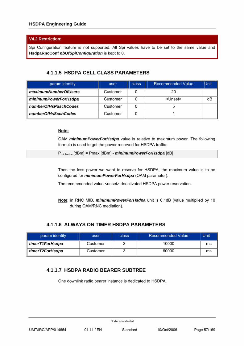
HSDPA Engineering Guide
Nortel confidential
UMT/IRC/APP/014654 01.11 / EN Standard 10/Oct/2006 Page 57/169
V4.2 Restriction:
Spi Configuration feature is not supported. All Spi values have to be set to the same value and HsdpaRncConf nbOfSpiConfiguration is kept to 0.
4.1.1.5 HSDPA CELL CLASS PARAMETERS
param identity user class Recommended Value Unit
maximumNumberOfUsers Customer 0 20
minimumPowerForHsdpa Customer 0 <Unset> dB
numberOfHsPdschCodes Customer 0 5
numberOfHsScchCodes Customer 0 1
Note:
OAM minimumPowerForHsdpa value is relative to maximum power. The following formula is used to get the power reserved for HSDPA traffic:
Pminhsdpa [dBm] = Pmax [dBm] - minimumPowerForHsdpa [dB]
Then the less power we want to reserve for HSDPA, the maximum value is to be configured for minimumPowerForHsdpa (OAM parameter).
The recommended value <unset> deactivated HSDPA power reservation.
Note: in RNC MIB, minimumPowerForHsdpa unit is 0.1dB (value multiplied by 10 during OAM/RNC mediation).
4.1.1.6 ALWAYS ON TIMER HSDPA PARAMETERS
param identity user class Recommended Value Unit
timerT1ForHsdpa Customer 3 10000 ms
timerT2ForHsdpa Customer 3 60000 ms
4.1.1.7 HSDPA RADIO BEARER SUBTREE
One downlink radio bearer instance is dedicated to HSDPA.
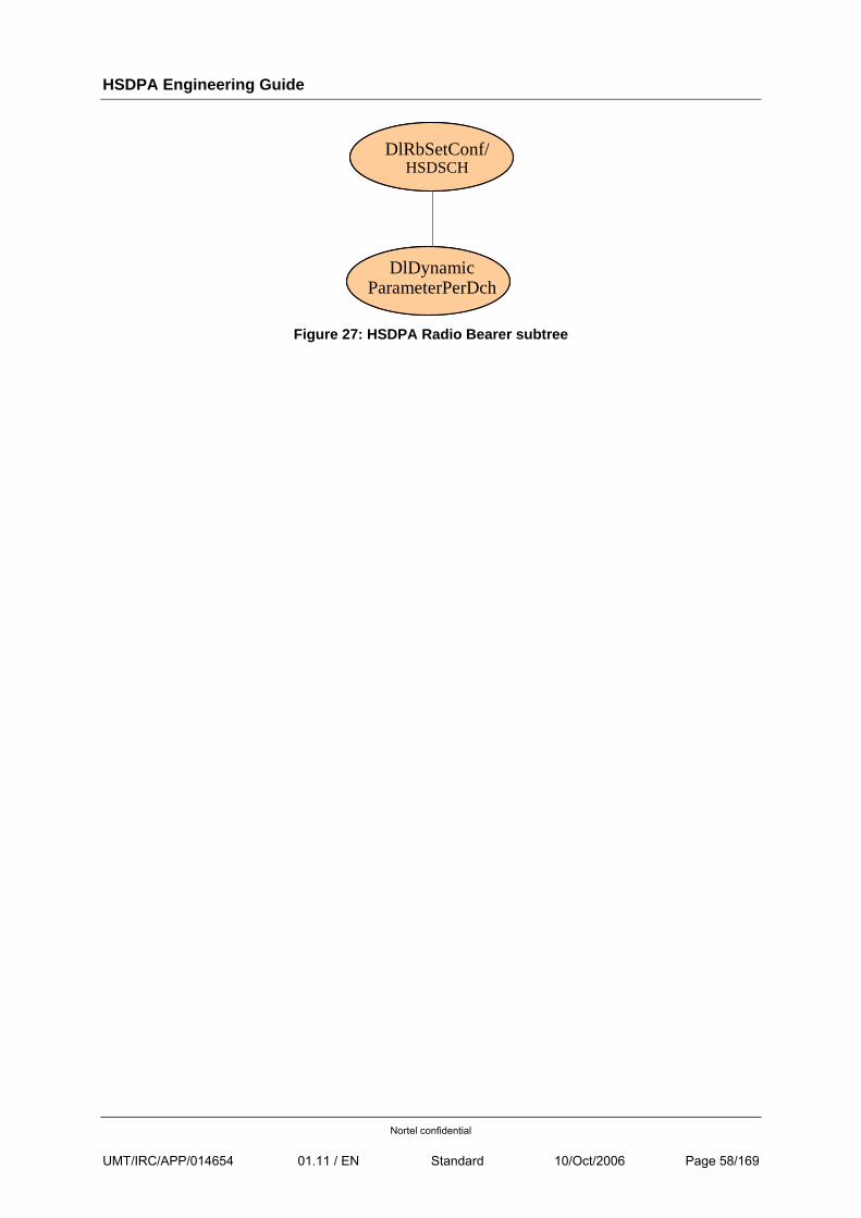
HSDPA Engineering Guide
Nortel confidential
UMT/IRC/APP/014654 01.11 / EN Standard 10/Oct/2006 Page 58/169
DlRbSetConf/HSDSCH
DlDynamicParameterPerDch
Figure 27: HSDPA Radio Bearer subtree
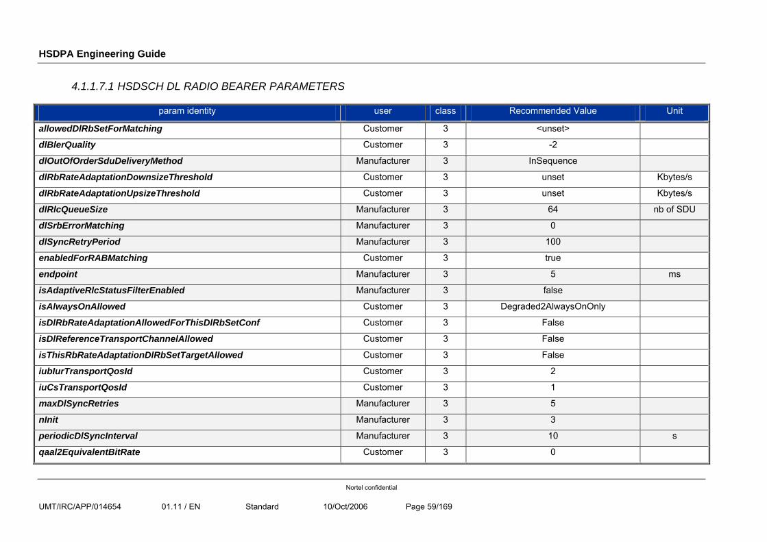
HSDPA Engineering Guide
Nortel confidential
UMT/IRC/APP/014654 01.11 / EN Standard 10/Oct/2006 Page 59/169
4.1.1.7.1 HSDSCH DL RADIO BEARER PARAMETERS
param identity user class Recommended Value Unit
allowedDlRbSetForMatching Customer 3 <unset>
dlBlerQuality Customer 3 -2
dlOutOfOrderSduDeliveryMethod Manufacturer 3 InSequence
dlRbRateAdaptationDownsizeThreshold Customer 3 unset Kbytes/s
dlRbRateAdaptationUpsizeThreshold Customer 3 unset Kbytes/s
dlRlcQueueSize Manufacturer 3 64 nb of SDU
dlSrbErrorMatching Manufacturer 3 0
dlSyncRetryPeriod Manufacturer 3 100
enabledForRABMatching Customer 3 true
endpoint Manufacturer 3 5 ms
isAdaptiveRlcStatusFilterEnabled Manufacturer 3 false
isAlwaysOnAllowed Customer 3 Degraded2AlwaysOnOnly
isDlRbRateAdaptationAllowedForThisDlRbSetConf Customer 3 False
isDlReferenceTransportChannelAllowed Customer 3 False
isThisRbRateAdaptationDlRbSetTargetAllowed Customer 3 False
iubIurTransportQosId Customer 3 2
iuCsTransportQosId Customer 3 1
maxDlSyncRetries Manufacturer 3 5
nInit Manufacturer 3 3
periodicDlSyncInterval Manufacturer 3 10 s
qaal2EquivalentBitRate Customer 3 0
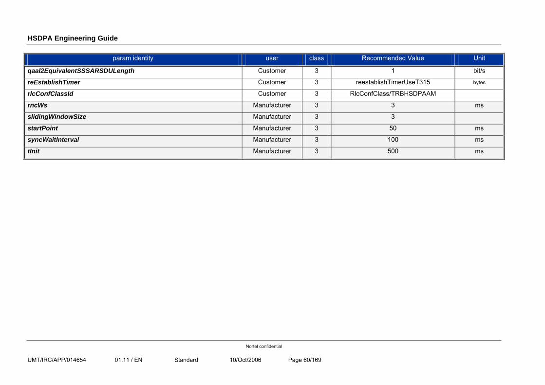
HSDPA Engineering Guide
Nortel confidential
UMT/IRC/APP/014654 01.11 / EN Standard 10/Oct/2006 Page 60/169
param identity user class Recommended Value Unit
qaal2EquivalentSSSARSDULength Customer 3 1 bit/s
reEstablishTimer Customer 3 reestablishTimerUseT315 bytes
rlcConfClassId Customer 3 RlcConfClass/TRBHSDPAAM
rncWs Manufacturer 3 3 ms
slidingWindowSize Manufacturer 3 3
startPoint Manufacturer 3 50 ms
syncWaitInterval Manufacturer 3 100 ms
tInit Manufacturer 3 500 ms
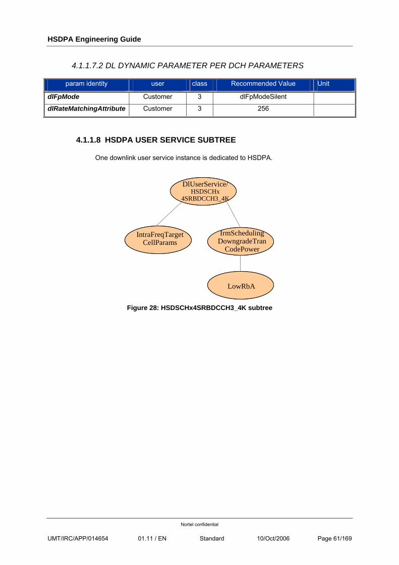
HSDPA Engineering Guide
Nortel confidential
UMT/IRC/APP/014654 01.11 / EN Standard 10/Oct/2006 Page 61/169
4.1.1.7.2 DL DYNAMIC PARAMETER PER DCH PARAMETERS
param identity user class Recommended Value Unit
dlFpMode Customer 3 dlFpModeSilent
dlRateMatchingAttribute Customer 3 256
4.1.1.8 HSDPA USER SERVICE SUBTREE
One downlink user service instance is dedicated to HSDPA.
DlUserService/HSDSCHx
4SRBDCCH3_4K
IntraFreqTargetCellParams
IrmSchedulingDowngradeTran
CodePower
LowRbA
Figure 28: HSDSCHx4SRBDCCH3_4K subtree
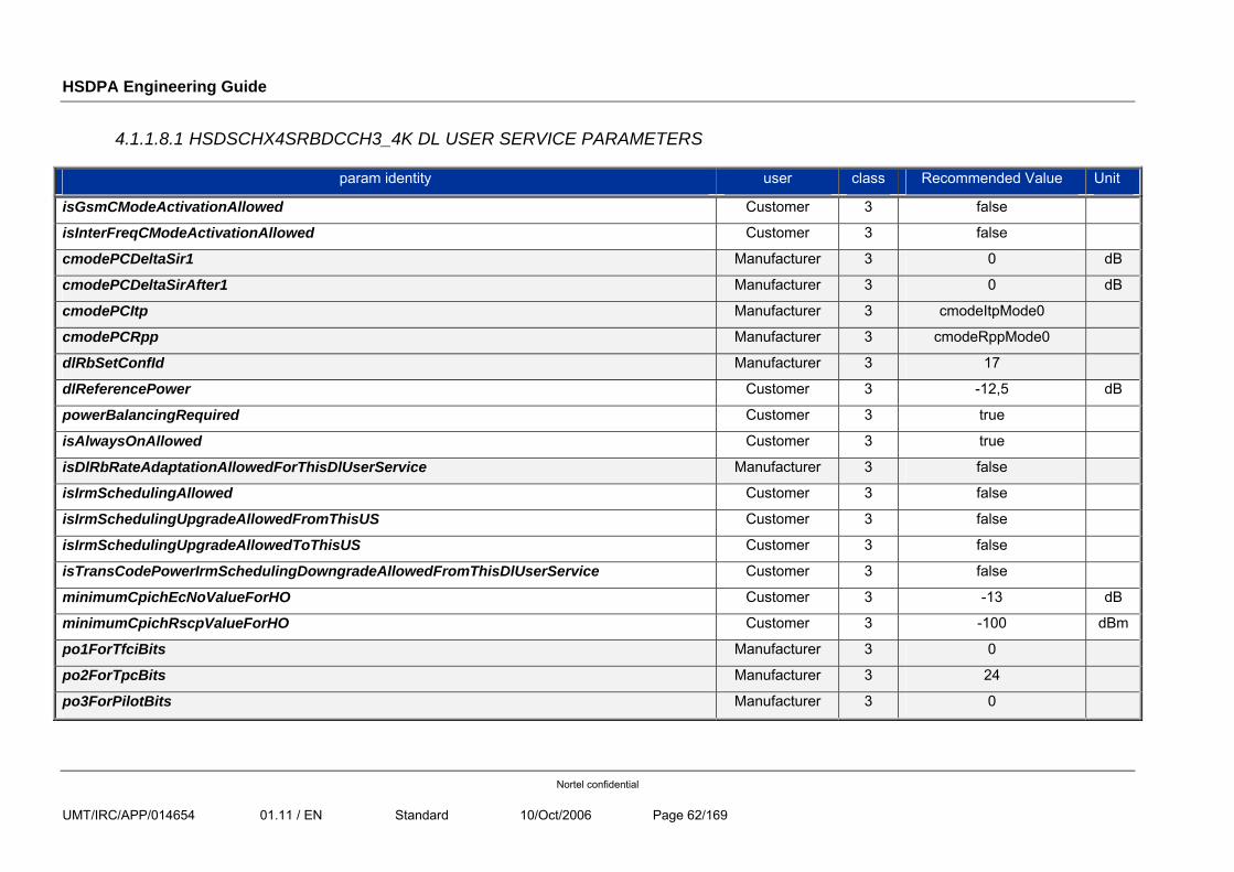
HSDPA Engineering Guide
Nortel confidential
UMT/IRC/APP/014654 01.11 / EN Standard 10/Oct/2006 Page 62/169
4.1.1.8.1 HSDSCHX4SRBDCCH3_4K DL USER SERVICE PARAMETERS
param identity user class Recommended Value Unit
isGsmCModeActivationAllowed Customer 3 false
isInterFreqCModeActivationAllowed Customer 3 false
cmodePCDeltaSir1 Manufacturer 3 0 dB
cmodePCDeltaSirAfter1 Manufacturer 3 0 dB
cmodePCItp Manufacturer 3 cmodeItpMode0
cmodePCRpp Manufacturer 3 cmodeRppMode0
dlRbSetConfId Manufacturer 3 17
dlReferencePower Customer 3 -12,5 dB
powerBalancingRequired Customer 3 true
isAlwaysOnAllowed Customer 3 true
isDlRbRateAdaptationAllowedForThisDlUserService Manufacturer 3 false
isIrmSchedulingAllowed Customer 3 false
isIrmSchedulingUpgradeAllowedFromThisUS Customer 3 false
isIrmSchedulingUpgradeAllowedToThisUS Customer 3 false
isTransCodePowerIrmSchedulingDowngradeAllowedFromThisDlUserService Customer 3 false
minimumCpichEcNoValueForHO Customer 3 -13 dB
minimumCpichRscpValueForHO Customer 3 -100 dBm
po1ForTfciBits Manufacturer 3 0
po2ForTpcBits Manufacturer 3 24
po3ForPilotBits Manufacturer 3 0
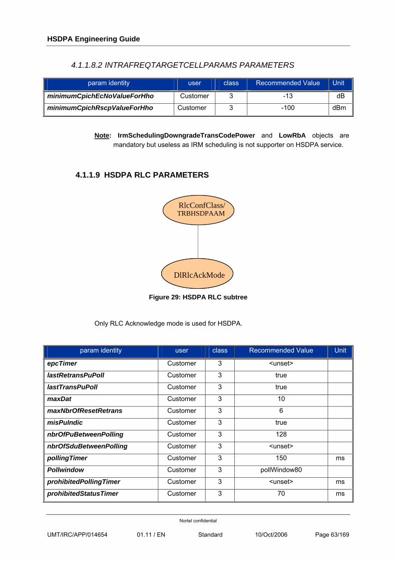
HSDPA Engineering Guide
Nortel confidential
UMT/IRC/APP/014654 01.11 / EN Standard 10/Oct/2006 Page 63/169
4.1.1.8.2 INTRAFREQTARGETCELLPARAMS PARAMETERS
param identity user class Recommended Value Unit
minimumCpichEcNoValueForHho Customer 3 -13 dB
minimumCpichRscpValueForHho Customer 3 -100 dBm
Note: IrmSchedulingDowngradeTransCodePower and LowRbA objects are mandatory but useless as IRM scheduling is not supporter on HSDPA service.
4.1.1.9 HSDPA RLC PARAMETERS
RlcConfClass/TRBHSDPAAM
DlRlcAckMode
Figure 29: HSDPA RLC subtree
Only RLC Acknowledge mode is used for HSDPA.
param identity user class Recommended Value Unit
epcTimer Customer 3 <unset>
lastRetransPuPoll Customer 3 true
lastTransPuPoll Customer 3 true
maxDat Customer 3 10
maxNbrOfResetRetrans Customer 3 6
misPuIndic Customer 3 true
nbrOfPuBetweenPolling Customer 3 128
nbrOfSduBetweenPolling Customer 3 <unset>
pollingTimer Customer 3 150 ms
Pollwindow Customer 3 pollWindow80
prohibitedPollingTimer Customer 3 <unset> ms
prohibitedStatusTimer Customer 3 70 ms
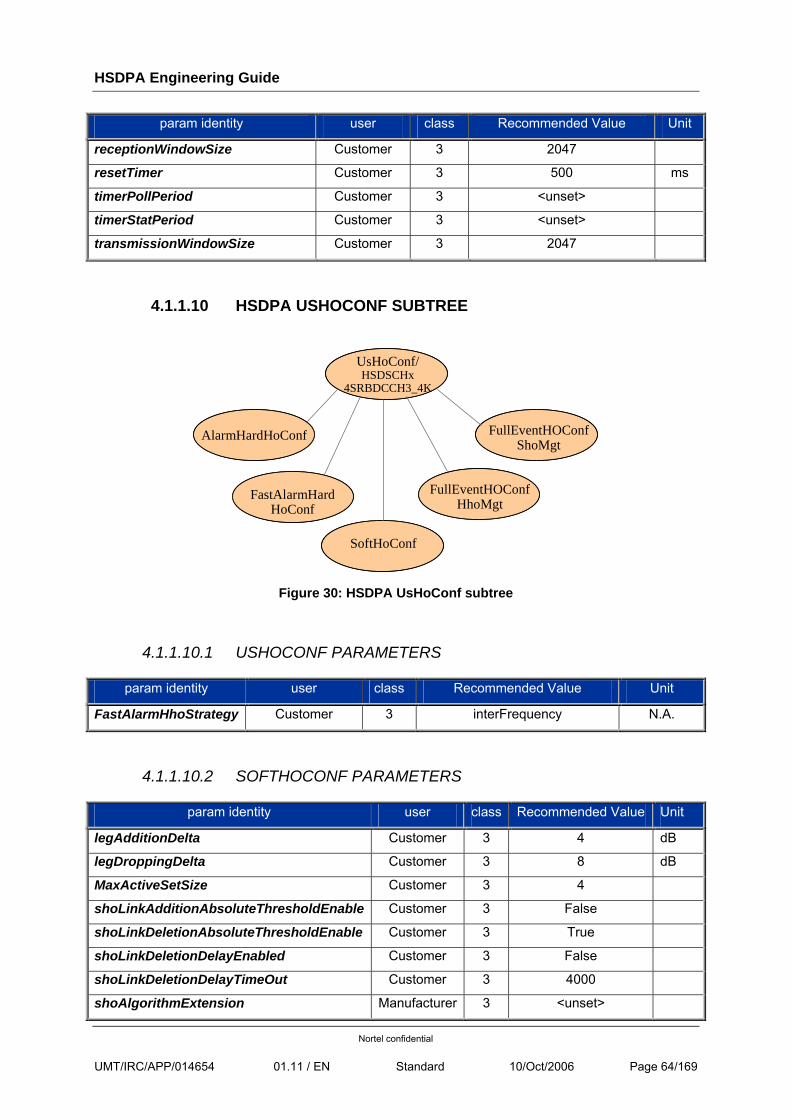
HSDPA Engineering Guide
Nortel confidential
UMT/IRC/APP/014654 01.11 / EN Standard 10/Oct/2006 Page 64/169
param identity user class Recommended Value Unit
receptionWindowSize Customer 3 2047
resetTimer Customer 3 500 ms
timerPollPeriod Customer 3 <unset>
timerStatPeriod Customer 3 <unset>
transmissionWindowSize Customer 3 2047
4.1.1.10 HSDPA USHOCONF SUBTREE
UsHoConf/HSDSCHx
4SRBDCCH3_4K
AlarmHardHoConf
FastAlarmHardHoConf
SoftHoConf
FullEventHOConfShoMgt
FullEventHOConfHhoMgt
Figure 30: HSDPA UsHoConf subtree
4.1.1.10.1 USHOCONF PARAMETERS
param identity user class Recommended Value Unit
FastAlarmHhoStrategy Customer 3 interFrequency N.A.
4.1.1.10.2 SOFTHOCONF PARAMETERS
param identity user class Recommended Value Unit
legAdditionDelta Customer 3 4 dB
legDroppingDelta Customer 3 8 dB
MaxActiveSetSize Customer 3 4
shoLinkAdditionAbsoluteThresholdEnable Customer 3 False
shoLinkDeletionAbsoluteThresholdEnable Customer 3 True
shoLinkDeletionDelayEnabled Customer 3 False
shoLinkDeletionDelayTimeOut Customer 3 4000
shoAlgorithmExtension Manufacturer 3 <unset>
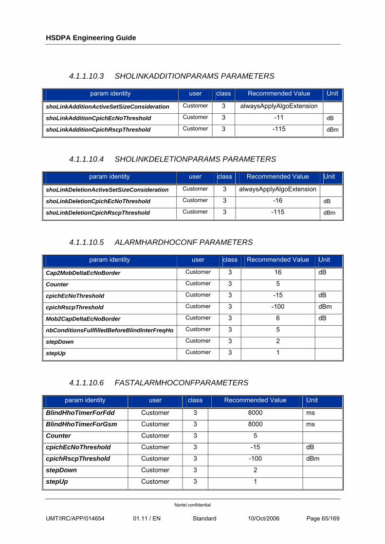
HSDPA Engineering Guide
Nortel confidential
UMT/IRC/APP/014654 01.11 / EN Standard 10/Oct/2006 Page 65/169
4.1.1.10.3 SHOLINKADDITIONPARAMS PARAMETERS
param identity user class Recommended Value Unit
shoLinkAdditionActiveSetSizeConsideration Customer 3 alwaysApplyAlgoExtension
shoLinkAdditionCpichEcNoThreshold Customer 3 -11 dB
shoLinkAdditionCpichRscpThreshold Customer 3 -115 dBm
4.1.1.10.4 SHOLINKDELETIONPARAMS PARAMETERS
param identity user class Recommended Value Unit
shoLinkDeletionActiveSetSizeConsideration Customer 3 alwaysApplyAlgoExtension
shoLinkDeletionCpichEcNoThreshold Customer 3 -16 dB
shoLinkDeletionCpichRscpThreshold Customer 3 -115 dBm
4.1.1.10.5 ALARMHARDHOCONF PARAMETERS
param identity user class Recommended Value Unit
Cap2MobDeltaEcNoBorder Customer 3 16 dB
Counter Customer 3 5
cpichEcNoThreshold Customer 3 -15 dB
cpichRscpThreshold Customer 3 -100 dBm
Mob2CapDeltaEcNoBorder Customer 3 6 dB
nbConditionsFullfilledBeforeBlindInterFreqHo Customer 3 5
stepDown Customer 3 2
stepUp Customer 3 1
4.1.1.10.6 FASTALARMHOCONFPARAMETERS
param identity user class Recommended Value Unit
BlindHhoTimerForFdd Customer 3 8000 ms
BlindHhoTimerForGsm Customer 3 8000 ms
Counter Customer 3 5
cpichEcNoThreshold Customer 3 -15 dB
cpichRscpThreshold Customer 3 -100 dBm
stepDown Customer 3 2
stepUp Customer 3 1
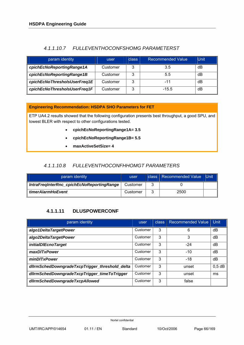
HSDPA Engineering Guide
Nortel confidential
UMT/IRC/APP/014654 01.11 / EN Standard 10/Oct/2006 Page 66/169
4.1.1.10.7 FULLEVENTHOCONFSHOMG PARAMETERST
param identity user class Recommended Value Unit
cpichEcNoReportingRange1A Customer 3 3.5 dB
cpichEcNoReportingRange1B Customer 3 5.5 dB
cpichEcNoThresholsUserFreq1E Customer 3 -11 dB
cpichEcNoThresholsUserFreq1F Customer 3 -15.5 dB
Engineering Recommendation: HSDPA SHO Parameters for FET
ETP UA4.2 results showed that the following configuration presents best throughput, a good SPU, and lowest BLER with respect to other configurations tested.
• cpichEcNoReportingRange1A= 3.5
• cpichEcNoReportingRange1B= 5.5
• maxActiveSetSize= 4
4.1.1.10.8 FULLEVENTHOCONFHHOMGT PARAMETERS
param identity user class Recommended Value Unit
IntraFreqInterRnc_cpichEcNoReportingRange Customer 3 0
timerAlarmHoEvent Customer 3 2500
4.1.1.11 DLUSPOWERCONF
param identity user class Recommended Value Unit
algo1DeltaTargetPower Customer 3 6 dB
algo2DeltaTargetPower Customer 3 3 dB
initialDlEcnoTarget Customer 3 -24 dB
maxDlTxPower Customer 3 -10 dB
minDlTxPower Customer 3 -18 dB
dlIrmSchedDowngradeTxcpTrigger_threshold_delta Customer 3 unset 0,5 dB
dlIrmSchedDowngradeTxcpTrigger_timeToTrigger Customer 3 unset ms
dlIrmSchedDowngradeTxcpAllowed Customer 3 false
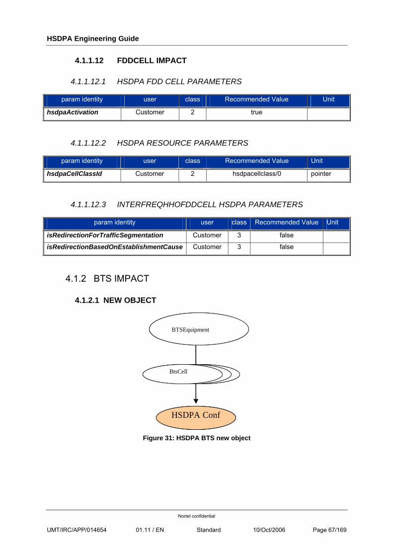
HSDPA Engineering Guide
Nortel confidential
UMT/IRC/APP/014654 01.11 / EN Standard 10/Oct/2006 Page 67/169
4.1.1.12 FDDCELL IMPACT
4.1.1.12.1 HSDPA FDD CELL PARAMETERS
param identity user class Recommended Value Unit
hsdpaActivation Customer 2 true
4.1.1.12.2 HSDPA RESOURCE PARAMETERS
param identity user class Recommended Value Unit
hsdpaCellClassId Customer 2 hsdpacellclass/0 pointer
4.1.1.12.3 INTERFREQHHOFDDCELL HSDPA PARAMETERS
param identity user class Recommended Value Unit
isRedirectionForTrafficSegmentation Customer 3 false
isRedirectionBasedOnEstablishmentCause Customer 3 false
4.1.2 BTS IMPACT
4.1.2.1 NEW OBJECT
BTSEquipment
HSDPA Conf
FddCellFddCellBtsCell
BTSEquipment
HSDPA Conf
FddCellFddCellBtsCell
Figure 31: HSDPA BTS new object
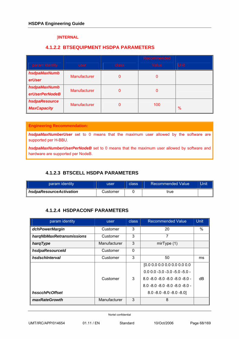
HSDPA Engineering Guide
Nortel confidential
UMT/IRC/APP/014654 01.11 / EN Standard 10/Oct/2006 Page 68/169
[INTERNAL
4.1.2.2 BTSEQUIPMENT HSDPA PARAMETERS
param identity user class
Recommended
Value Unit
hsdpaMaxNumb
erUser Manufacturer 0 0
hsdpaMaxNumberUserPerNodeB
Manufacturer 0 0
hsdpaResourceMaxCapacity
Manufacturer 0 100 %
Engineering Recommendation:
hsdpaMaxNumberUser set to 0 means that the maximum user allowed by the software are supported per H-BBU.
hsdpaMaxNumberUserPerNodeB set to 0 means that the maximum user allowed by software and hardware are supported per NodeB.
4.1.2.3 BTSCELL HSDPA PARAMETERS
param identity user class Recommended Value Unit
hsdpaResourceActivation Customer 0 true
4.1.2.4 HSDPACONF PARAMETERS
param identity user class Recommended Value Unit
dchPowerMargin Customer 3 20 %
harqNbMaxRetransmissions Customer 3 7
harqType Manufacturer 3 mirType (1)
hsdpaResourceId Customer 0
hsdschInterval Customer 3 50 ms
hsscchPcOffset
Customer 3
[0.0 0.0 0.0 0.0 0.0 0.0 0.0
0.0 0.0 -3.0 -3.0 -5.0 -5.0 -
8.0 -8.0 -8.0 -8.0 -8.0 -8.0 -
8.0 -8.0 -8.0 -8.0 -8.0 -8.0 -
8.0 -8.0 -8.0 -8.0 -8.0]
dB
maxRateGrowth Manufacturer 3 8
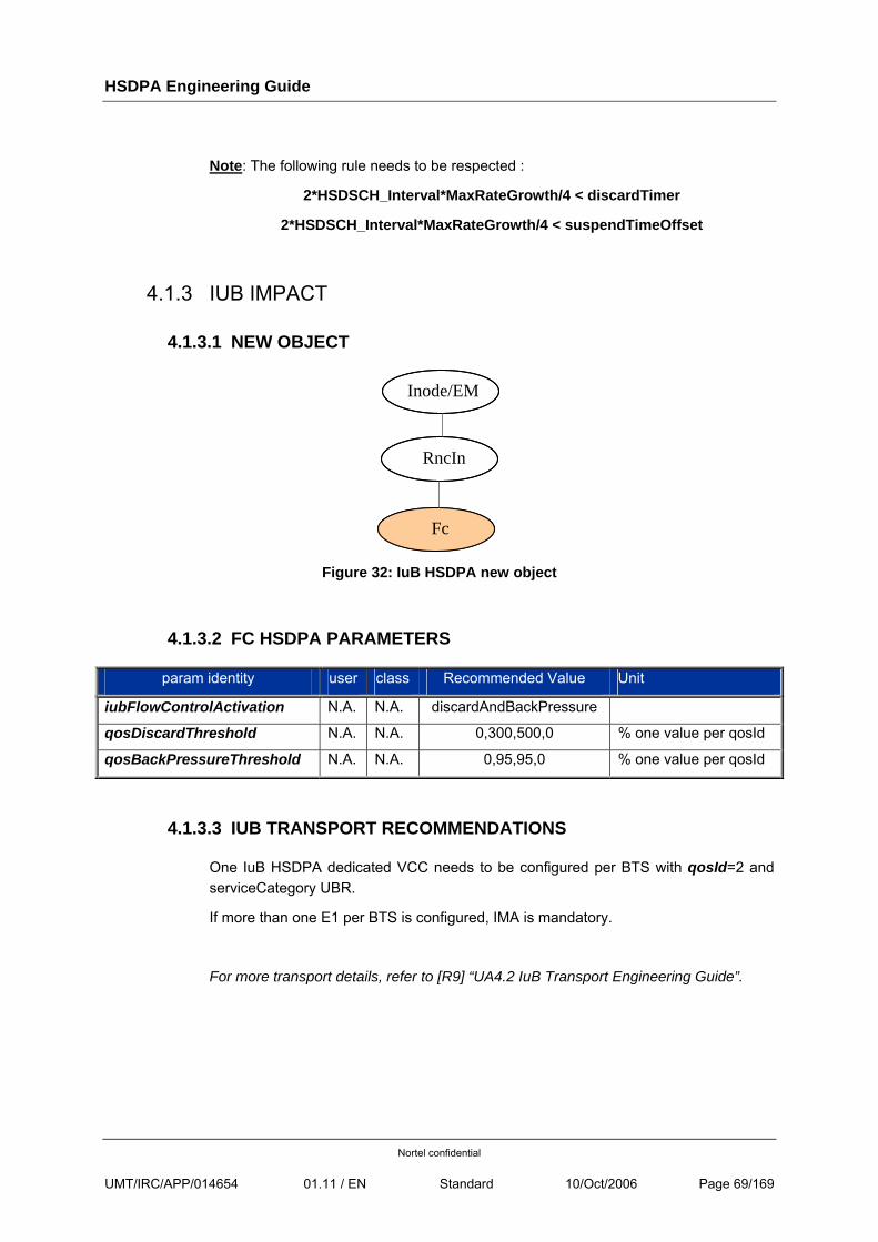
HSDPA Engineering Guide
Nortel confidential
UMT/IRC/APP/014654 01.11 / EN Standard 10/Oct/2006 Page 69/169
Note: The following rule needs to be respected :
2*HSDSCH_Interval*MaxRateGrowth/4 < discardTimer
2*HSDSCH_Interval*MaxRateGrowth/4 < suspendTimeOffset
4.1.3 IUB IMPACT
4.1.3.1 NEW OBJECT
Inode/EM
RncIn
Fc
Figure 32: IuB HSDPA new object
4.1.3.2 FC HSDPA PARAMETERS
param identity user class Recommended Value Unit
iubFlowControlActivation N.A. N.A. discardAndBackPressure
qosDiscardThreshold N.A. N.A. 0,300,500,0 % one value per qosId
qosBackPressureThreshold N.A. N.A. 0,95,95,0 % one value per qosId
4.1.3.3 IUB TRANSPORT RECOMMENDATIONS
One IuB HSDPA dedicated VCC needs to be configured per BTS with qosId=2 and serviceCategory UBR.
If more than one E1 per BTS is configured, IMA is mandatory.
For more transport details, refer to [R9] “UA4.2 IuB Transport Engineering Guide”.
HSDPA Engineering Guide
Nortel confidential
UMT/IRC/APP/014654 01.11 / EN Standard 10/Oct/2006 Page 70/169
4.2 HSDPA ACTIVATION
Refer to [R10] NTP 411-8111-575 “HSDPA Feature Activation Procedure” posted at www.nortel.com.
[INTERNAL
Draft available at:
http://eur-livelink.europe.nortel.com/livelink/livelink.exe?func=ll&objId=14383419].
HSDPA Engineering Guide
Nortel confidential
UMT/IRC/APP/014654 01.11 / EN Standard 10/Oct/2006 Page 71/169
[INTERNAL
5 HSDPA COUNTERS & METRICS
The UA4.2 HSDPA metrics list and the Metrics Definition document ([Internal_R1]) can be found @
http://eur-livelink.europe.nortel.com/livelink/livelink.exe?func=ll&objId=16255639
]
HSDPA Engineering Guide
Nortel confidential
UMT/IRC/APP/014654 01.11 / EN Standard 10/Oct/2006 Page 72/169
6 UA4.2 HSDPA SPECIFIC FEATURES & IMPACT ON EXISTING ALGORITHMS
6.1 ALWAYS ON
6.1.1 MECHANISM
The always-on mechanism applies to HSDPA the same way as for R99 radio bearers.
• In R99, Always-on is applicable only for Interactive/Background traffic.
• In UA4.2, only Interactive/Background traffic is mapped on HSDPA. Then, Always-on applies to all traffic carried by HSDPA.
In the both cases, Always-on allows to optimize radio resource usage for bursty traffic (low activity factor):
• In DL, the HSDPA CAC allows a limited number of users connected simultaneously on HSDPA (H-BBU hardware limitation). That’s why we should not keep users connected too long if they are not transmitting, preventing other users from being accepted on HSDPA.
• In UL, the matter is the same as for R99 traffic because UL traffic associated to HSDPA is carried on a DCH. Keeping users connected too long on HSDPA is a waste of radio resources (CEM).
Moreover, for HSDPA, specific signalling procedure for HS-DSCH Flow Control mechanism induces additional RNC processing during entire connection time, even inactivity periods (periodic message during all connection time on HSDPA).
The monitoring of user activity at RLC level (DTCH) for both UL and DL is the same as for R99. Nevertheless, some new parameters appear. Let’s introduce them in the next chapters.
6.1.2 ACTIVATION & MODE
6.1.2.1 ACTIVATION
Always-on has to be activated on HSDPA. 3 parameters are to be set:
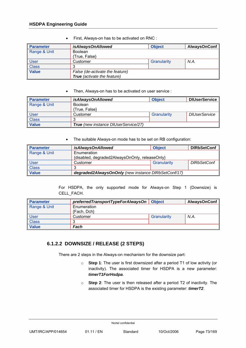
HSDPA Engineering Guide
Nortel confidential
UMT/IRC/APP/014654 01.11 / EN Standard 10/Oct/2006 Page 73/169
• First, Always-on has to be activated on RNC :
Parameter isAlwaysOnAllowed Object AlwaysOnConfRange & Unit Boolean
{True, False} User Customer Class 3
Granularity N.A.
Value False (de-activate the feature) True (activate the feature)
• Then, Always-on has to be activated on user service :
Parameter isAlwaysOnAllowed Object DlUserServiceRange & Unit Boolean
{True, False} User Customer Class 3
Granularity DlUserService
Value True (new instance DlUserService/27)
• The suitable Always-on mode has to be set on RB configuration:
Parameter isAlwaysOnAllowed Object DlRbSetConf Range & Unit Enumeration
{disabled, degraded2AlwaysOnOnly, releaseOnly} User Customer Class 3
Granularity DlRbSetConf
Value degraded2AlwaysOnOnly (new instance DlRbSetConf/17)
For HSDPA, the only supported mode for Always-on Step 1 (Downsize) is CELL_FACH.
Parameter preferredTransportTypeForAlwaysOn Object AlwaysOnConfRange & Unit Enumeration
{Fach, Dch} User Customer Class 3
Granularity N.A.
Value Fach
6.1.2.2 DOWNSIZE / RELEASE (2 STEPS)
There are 2 steps in the Always-on mechanism for the downsize part:
o Step 1: The user is first downsized after a period T1 of low activity (or inactivity). The associated timer for HSDPA is a new parameter: timerT1ForHsdpa.
o Step 2: The user is then released after a period T2 of inactivity. The associated timer for HSDPA is the existing parameter: timerT2.
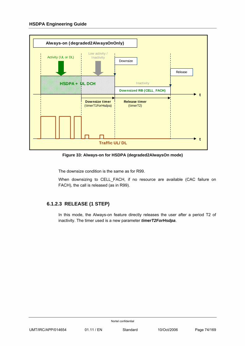
HSDPA Engineering Guide
Nortel confidential
UMT/IRC/APP/014654 01.11 / EN Standard 10/Oct/2006 Page 74/169
Figure 33: Always-on for HSDPA (degraded2AlwaysOn mode)
The downsize condition is the same as for R99.
When downsizing to CELL_FACH, if no resource are available (CAC failure on FACH), the call is released (as in R99).
6.1.2.3 RELEASE (1 STEP)
In this mode, the Always-on feature directly releases the user after a period T2 of inactivity. The timer used is a new parameter timerT2ForHsdpa.
Activity (UL or DL)Low activity /
Inactivity
Downsize timer(timerT1ForHsdpa)
HSDPA + UL DCH
Downsized RB (CELL_FACH)
Release timer (timerT2)
t
Always-on (degraded2AlwaysOnOnly)
Downsize
Release
Inactivity
t Traffic UL/DL
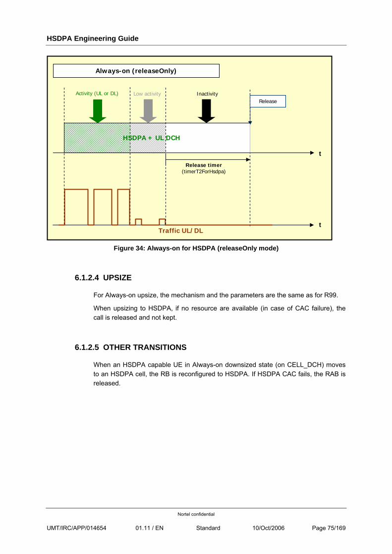
HSDPA Engineering Guide
Nortel confidential
UMT/IRC/APP/014654 01.11 / EN Standard 10/Oct/2006 Page 75/169
Figure 34: Always-on for HSDPA (releaseOnly mode)
6.1.2.4 UPSIZE
For Always-on upsize, the mechanism and the parameters are the same as for R99.
When upsizing to HSDPA, if no resource are available (in case of CAC failure), the call is released and not kept.
6.1.2.5 OTHER TRANSITIONS
When an HSDPA capable UE in Always-on downsized state (on CELL_DCH) moves to an HSDPA cell, the RB is reconfigured to HSDPA. If HSDPA CAC fails, the RAB is released.
Activity (UL or DL) Low activity
Release timer(timerT2ForHsdpa)
t
Always-on (releaseOnly)
ReleaseInactivity
t Traffic UL/DL
HSDPA + UL DCH
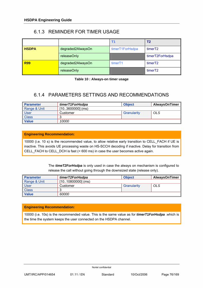
HSDPA Engineering Guide
Nortel confidential
UMT/IRC/APP/014654 01.11 / EN Standard 10/Oct/2006 Page 76/169
6.1.3 REMINDER FOR TIMER USAGE
Always-on mode T1 T2
degraded2AlwaysOn timerT1ForHsdpa timerT2 HSDPA
releaseOnly timerT2ForHsdpa
degraded2AlwaysOn timerT1 timerT2 R99
releaseOnly timerT2
Table 10 : Always-on timer usage
6.1.4 PARAMETERS SETTINGS AND RECOMMENDATIONS
Parameter timerT1ForHsdpa Object AlwaysOnTimerRange & Unit [10..3600000] (ms) User Customer Class 3
Granularity OLS
Value 10000
Engineering Recommendation:
10000 (i.e. 10 s) is the recommended value, to allow relative early transition to CELL_FACH if UE is inactive. This avoids UE processing waste on HS-SCCH decoding if inactive. Delay for transition from CELL_FACH to CELL_DCH is fast (< 600 ms) in case the user becomes active again.
The timeT2ForHsdpa is only used in case the always on mechanism is configured to release the call without going through the downsized state (release only).
Parameter timerT2ForHsdpa Object AlwaysOnTimerRange & Unit [10..10800000] (ms) User Customer Class 3
Granularity OLS
Value 60000
Engineering Recommendation:
10000 (i.e. 10s) is the recommended value. This is the same value as for timerT1ForHsdpa .which is the time the system keeps the user connected on the HSDPA channel.
HSDPA Engineering Guide
Nortel confidential
UMT/IRC/APP/014654 01.11 / EN Standard 10/Oct/2006 Page 77/169
6.2 IRM ALGORITHMS
6.2.1 IRM SCHEDULING DOWNGRADE/UPGRADE INTERWORKING
HSDPA links are not eligible to iRM scheduling downgrade/upgrade procedures.
6.2.2 IRM CAC/IRM PRE-EMPTION INTERWORKING
HSDPA links are not eligible to iRM Cac/iRM Pre-Emption procedures since the throughput adaptation is provided by the Mac-hs scheduler i.e. the more users multiplexed on HS-DSCH, the less users will be allocated high bit rates.
However, as it is possible to reserve some power for HSDPA users, this power shall be consider as consumed in cell colour calculation for the HSDPA cells.
In the same way, OVSF codes reserved for HS-PDSCH and HS-SCCH are considered to be used in the cell colour calculation.
Refer to [R14] for more details on OVSF Code Load Thresholds with HSDPA.
On the Iub, the Iub load colour takes into account the actual traffic on the link on a selected set of VCC QoS, so may include or not HSDPA traffic according to operator’s provisioning.
6.2.3 RB ADAPTATION INTERWORKING
HSDPA links are not eligible to RB Adaptation procedures.
Note: the RB Adaptation is applied independently on the UL links (mapped on dch channels).
HSDPA Engineering Guide
Nortel confidential
UMT/IRC/APP/014654 01.11 / EN Standard 10/Oct/2006 Page 78/169
6.3 MOBILITY PROCEDURES
This section describes the existing mobility procedures for HSDPA calls.
If there is any error during any HSDPA mobility procedure or if it is not possible to re-establish HS-DSCH on the new primary (CAC failure), the RAB is released.
Mobiles can be spread over the HSDPA and the not-HSDPA layers thanks to the Traffic Segmentation feature at RRC connection establishment. However, note that the intra-RNC inter-frequency HO for capacity/mobility layers cannot be used with Traffic Segmentation (if one of the two twin cells is HSDPA configured).
6.3.1 INTRA-FREQUENCY MOBILITY
6.3.1.1 MOBILITY OF ASSOCIATED DCH
Soft and softer handovers are handled normally on the associated DCHs and the Active Set is managed as usual.
For more details, see the Mobility chapter in [R1]
6.3.1.2 MOBILITY OF HS-DSCH
As defined by 3GPP, HS-DSCH is established in only one cell so is never in soft handover. In Nortel implementation, the serving HS-DSCH RL always follows that of the primary cell.
Mobility is done as long as the target cell is HSDPA capable.
When the primary cell changes:
• If the former primary is no longer present in the new Active Set (following an Active Set Update procedure), the HS-DSCH link is immediately released (RNSAP RL Deletion) before the RRC Measurement Control procedure. A new HS-DSCH link is then setup –using a normal SRLR procedure– on the new primary cell, after the Measurement Control.
• If the former primary remains in the Active Set, the HS-DSCH RL is deleted on the former primary (right after the RRC Measurement Control procedure) and it is re-established under the new one synchronously via the RRC RB Reconfiguration message.
• If the new primary cell does not support HSDPA then the RB is reconfigured to DCH. iRM CAC is performed and if there is a CAC failure the call is dropped.
HSDPA Engineering Guide
Nortel confidential
UMT/IRC/APP/014654 01.11 / EN Standard 10/Oct/2006 Page 79/169
• If the new primary cell supports HSDPA while the former did not, then the RB is reconfigured to HS-DSCH. This is also applicable to the case where the UE was downgraded on DCH because of Always-On step1.
During the reconfiguration, data transfer is suspended by the RNC. Data that were in the Mac-hs buffer of the former cell are discarded (except if both cells are managed by the same H-BBU board). User data are not lost thanks to RLC retransmissions but if the primary cell changes too often, the data throughput can be impacted.
Engineering Recommendation: FET Recommandation for primary cell change
Even if ETP UA4.2 results showed similar performance for the actual configuration (Hysteresis1D= 6 & timeToTrigger1D=640) and for (Hysteresis1D= 4 & timeToTrigger1D=1280), we recommend the later one as a longer Time to Trigger is more constraining than a higher Hysteresis.
• Hysteresis1D= 4 (2dB)
• timeToTrigger1D= 1280
Refer to [R1] for more details on primary cell change algorithm
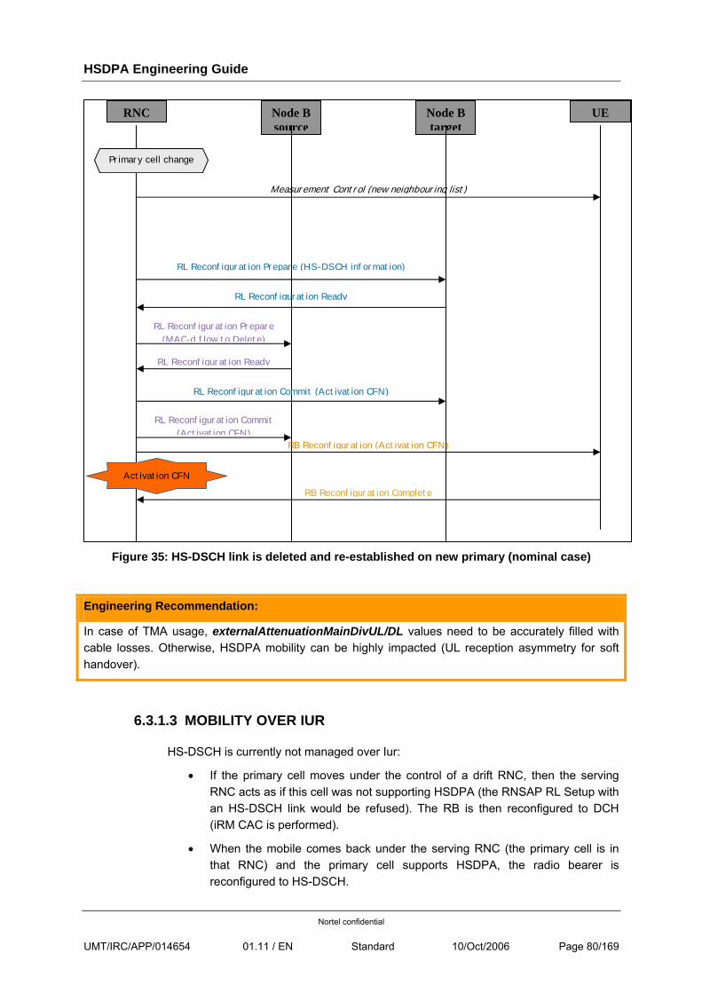
HSDPA Engineering Guide
Nortel confidential
UMT/IRC/APP/014654 01.11 / EN Standard 10/Oct/2006 Page 80/169
Figure 35: HS-DSCH link is deleted and re-established on new primary (nominal case)
Engineering Recommendation:
In case of TMA usage, externalAttenuationMainDivUL/DL values need to be accurately filled with cable losses. Otherwise, HSDPA mobility can be highly impacted (UL reception asymmetry for soft handover).
6.3.1.3 MOBILITY OVER IUR
HS-DSCH is currently not managed over Iur:
• If the primary cell moves under the control of a drift RNC, then the serving RNC acts as if this cell was not supporting HSDPA (the RNSAP RL Setup with an HS-DSCH link would be refused). The RB is then reconfigured to DCH (iRM CAC is performed).
• When the mobile comes back under the serving RNC (the primary cell is in that RNC) and the primary cell supports HSDPA, the radio bearer is reconfigured to HS-DSCH.
RNC Node B source
Node B target
UE
RB Reconfiguration (Activation CFN)
RL Reconfiguration Ready
Measurement Control (new neighbouring list)
RL Reconfiguration Prepare (HS-DSCH information)
RB Reconfiguration Complete
Primary cell change
RL Reconfiguration Ready
RL Reconfiguration Prepare (MAC-d flow to Delete)
RL Reconfiguration Commit (Activation CFN)
Activation CFN
RL Reconfiguration Commit (Activation CFN)
HSDPA Engineering Guide
Nortel confidential
UMT/IRC/APP/014654 01.11 / EN Standard 10/Oct/2006 Page 81/169
6.3.2 INTER-FREQUENCY MOBILITY
Inter-frequency hard handover is not supported for HSDPA calls.
If the mobile leaves the coverage of the HSDPA layer, the call is dropped from the source RNC perspective but the PDP context is still active (transparent to the user):
• The UE may perform a 3G cell reselection on a second frequency and then resume the 3G call. If the reselected primary cell is HSDPA capable, the call will be reconfigured to HSDPA after its re-establishment.
• The UE may be handed to 2G, either in blind mode or selecting the best cell (this last option is only possible when the mobile can make 2G measurements without compressed mode).
When the UE is on DCH and it performs an inter-frequency hard handover towards an HSDPA cell, the HHO will end on a DCH configuration even if all conditions to swap to HSDPA are fulfilled. Following the inter-frequency procedure, a primary radio link update procedure shall be performed, and it may lead to a HSDPA configuration.
In the case of an incoming handover from another UTRAN, the call will be also established on DCH. After the handover completion, the RNC will perform an UE Capability Enquiry procedure. If the UE is HSDPA capable then the RB is reconfigured to HSDPA (if the target cell is configured with HSDPA and if it is a mono PS I/B call).
6.3.3 INTER-SYSTEM MOBILITY
The RNC will not configure Compressed Mode when the call is on HSDPA. This does not prevent non-HSDPA calls from using CM. This also does not prevent mobiles that do not need CM to perform measurements to be handled normally (and perform mobility procedures with measurements) for the inter-RAT mobility.
If a call is switched from DCH to HS-DSCH while Compressed Mode is active (it was activated when the call was on DCH), CM is deactivated at HS-DSCH Activation Time.
6.3.3.1 3G TO 2G HANDOVER
Handover is supported for 3G-2G mobility.
The UE may be handed to 2G, either in blind mode or selecting the best cell (this last option is only possible if the mobile can make 2G measurements without compressed mode). The Compressed Mode is not supported for HSDPA calls in the current release.
If there are measurements available and valid, they must be used to determine the target GSM cell as usual.
The handover is triggered on the same alarm conditions than for non-HSDPA calls.
HSDPA Engineering Guide
Nortel confidential
UMT/IRC/APP/014654 01.11 / EN Standard 10/Oct/2006 Page 82/169
6.3.3.2 2G TO 3G HANDOVER
From the target RNC, this is seen as a new Mobile Originated PS call. The same rules as the initial admission apply, leading possibly to the allocation of HS-DSCH to the incoming UE.
6.3.4 U-PLANE TRAFFIC HANDLING
There are 2 aspects to consider during HSDPA mobility:
1. Traffic handling policy toward the source cell.
This policy is only applicable when the old serving HS-DSCH RL is still part of the Active Set. At time (Activation Time – Suspend Time Offset), the RNC no longer sends data to the source cell.
2. HS-DSCH credit acquisition policy from the target cell.
Based on the following NodeB behaviour specifications:
• All HS-DSCH Capacity Requests that are sent to the NodeB before the starting activation time are silently discarded.
• When the credits are not yet explicitly granted, the NodeB silently discards HS-DSCH data coming from the RNC (i.e. no HS-DSCH Capacity Allocation is sent to the RNC).
• After the activation time, on the first HS-DSCH Capacity Request with nonzero BO, the NodeB immediately replies with HS-DSCH Capacity Allocation.
• In the steady-state (after that first HS-DSCH Capacity Request message), the NodeB will reply to each non-zero BO HS-DSCH Capacity Request only if the buffer allows it. If not, the NodeB updates the BO information, drops the Request and waits for the next one. The NodeB periodically sends a new HS-DSCH Capacity Allocation to the RNC based on the BO that is piggy-backed in each HS-DSCH data frame (no need to wait for a Capacity Request).
The RNC HS-DSCH initial credit acquisition policy is as followed:
1. If an initial HS-DSCH credit is explicitly returned by the NodeB in the NBAP RL Reconfiguration Ready message, the RNC will start to use that credit at the activation time. Otherwise, the RNC will assume that the credits are set to zero. This is applicable to both intra and inter-NodeB mobility cases.
2. At the activation time, if the HS-DSCH credit is zero and there are outstanding data to be transmitted, the RNC will initiate the HS-DSCH Capacity Request
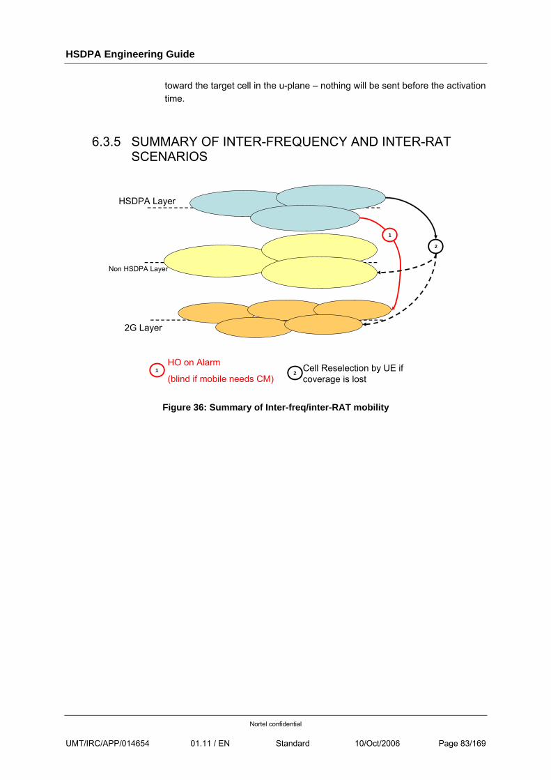
HSDPA Engineering Guide
Nortel confidential
UMT/IRC/APP/014654 01.11 / EN Standard 10/Oct/2006 Page 83/169
toward the target cell in the u-plane – nothing will be sent before the activation time.
6.3.5 SUMMARY OF INTER-FREQUENCY AND INTER-RAT SCENARIOS
Figure 36: Summary of Inter-freq/inter-RAT mobility
HSDPA Layer
Non HSDPA Layer
2G Layer
HO on Alarm
(blind if mobile needs CM)Cell Reselection by UE if coverage is lost
1
1
2
2
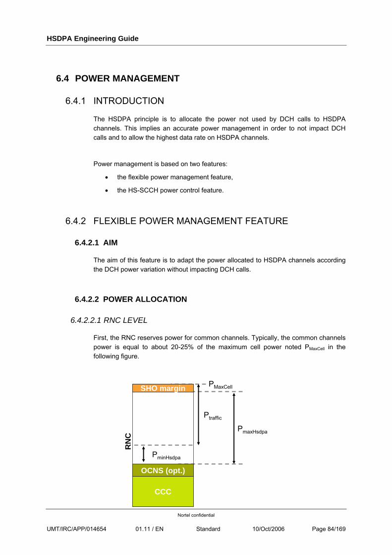
HSDPA Engineering Guide
Nortel confidential
UMT/IRC/APP/014654 01.11 / EN Standard 10/Oct/2006 Page 84/169
6.4 POWER MANAGEMENT
6.4.1 INTRODUCTION
The HSDPA principle is to allocate the power not used by DCH calls to HSDPA channels. This implies an accurate power management in order to not impact DCH calls and to allow the highest data rate on HSDPA channels.
Power management is based on two features:
• the flexible power management feature,
• the HS-SCCH power control feature.
6.4.2 FLEXIBLE POWER MANAGEMENT FEATURE
6.4.2.1 AIM
The aim of this feature is to adapt the power allocated to HSDPA channels according the DCH power variation without impacting DCH calls.
6.4.2.2 POWER ALLOCATION
6.4.2.2.1 RNC LEVEL
First, the RNC reserves power for common channels. Typically, the common channels power is equal to about 20-25% of the maximum cell power noted PMaxCell in the following figure.
PmaxHsdpa
CCC
SHO margin
RN
C
OCNS (opt.)
PminHsdpa
PMaxCell
Ptraffic
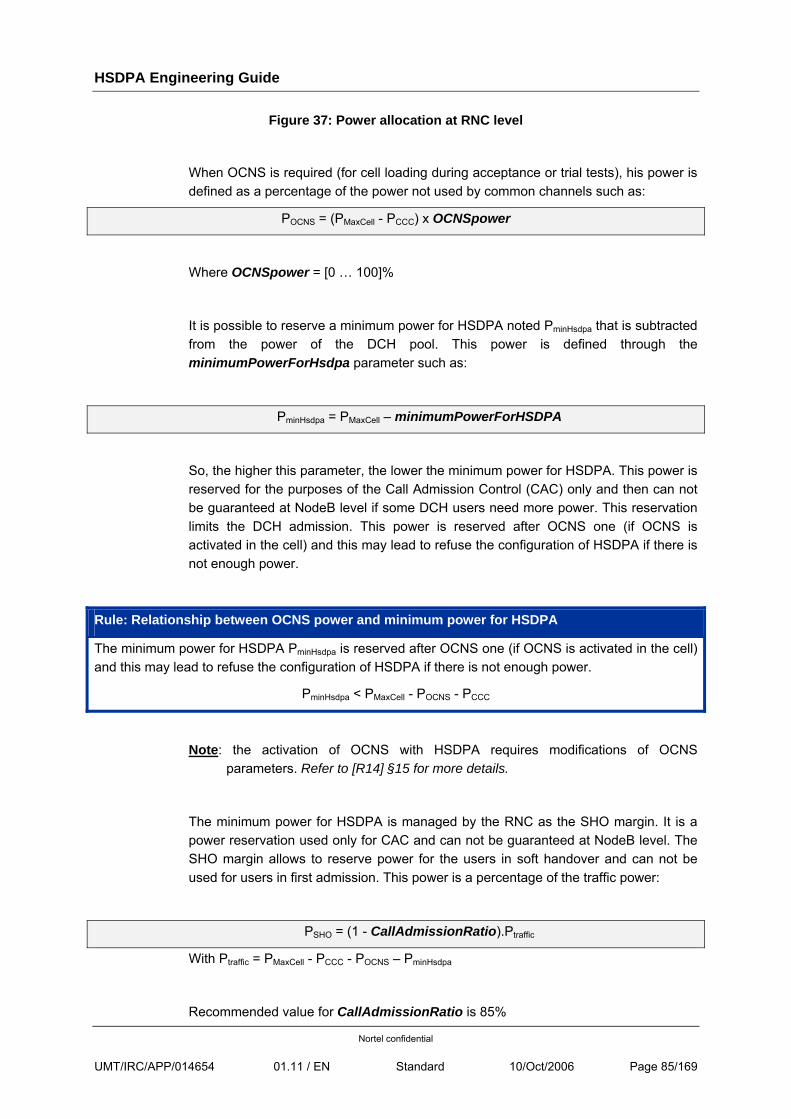
HSDPA Engineering Guide
Nortel confidential
UMT/IRC/APP/014654 01.11 / EN Standard 10/Oct/2006 Page 85/169
Figure 37: Power allocation at RNC level
When OCNS is required (for cell loading during acceptance or trial tests), his power is defined as a percentage of the power not used by common channels such as:
POCNS = (PMaxCell - PCCC) x OCNSpower
Where OCNSpower = [0 … 100]%
It is possible to reserve a minimum power for HSDPA noted PminHsdpa that is subtracted from the power of the DCH pool. This power is defined through the minimumPowerForHsdpa parameter such as:
PminHsdpa = PMaxCell – minimumPowerForHSDPA
So, the higher this parameter, the lower the minimum power for HSDPA. This power is reserved for the purposes of the Call Admission Control (CAC) only and then can not be guaranteed at NodeB level if some DCH users need more power. This reservation limits the DCH admission. This power is reserved after OCNS one (if OCNS is activated in the cell) and this may lead to refuse the configuration of HSDPA if there is not enough power.
Rule: Relationship between OCNS power and minimum power for HSDPA
The minimum power for HSDPA PminHsdpa is reserved after OCNS one (if OCNS is activated in the cell) and this may lead to refuse the configuration of HSDPA if there is not enough power.
PminHsdpa < PMaxCell - POCNS - PCCC
Note: the activation of OCNS with HSDPA requires modifications of OCNS parameters. Refer to [R14] §15 for more details.
The minimum power for HSDPA is managed by the RNC as the SHO margin. It is a power reservation used only for CAC and can not be guaranteed at NodeB level. The SHO margin allows to reserve power for the users in soft handover and can not be used for users in first admission. This power is a percentage of the traffic power:
PSHO = (1 - CallAdmissionRatio).Ptraffic
With Ptraffic = PMaxCell - PCCC - POCNS – PminHsdpa
Recommended value for CallAdmissionRatio is 85%
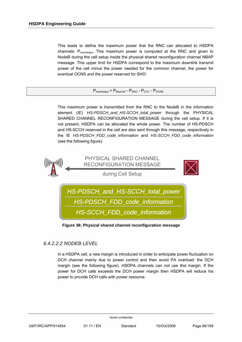
HSDPA Engineering Guide
Nortel confidential
UMT/IRC/APP/014654 01.11 / EN Standard 10/Oct/2006 Page 86/169
This leads to define the maximum power that the RNC can allocated to HSDPA channels: PmaxHsdpa. This maximum power is computed at the RNC and given to NodeB during the cell setup inside the physical shared reconfiguration channel NBAP message. This upper limit for HSDPA correspond to the maximum downlink transmit power of the cell minus the power needed for the common channel, the power for eventual OCNS and the power reserved for SHO:
PmaxHsdpa = PMaxCell - PSHO - PCCC - POCNS
This maximum power is transmitted from the RNC to the NodeB in the information element (IE) HS-PDSCH_and_HS-SCCH_total_power through the PHYSICAL SHARED CHANNEL RECONFIGURATION MESSAGE during the cell setup. If it is not present, HSDPA can be allocated the whole power. The number of HS-PDSCH and HS-SCCH reserved in the cell are also sent through this message, respectively in the IE HS-PDSCH_FDD_code_information and HS-SCCH_FDD_code_information (see the following figure).
PHYSICAL SHARED CHANNEL RECONFIGURATION MESSAGE
during Cell Setup
HS-PDSCH_FDD_code_information
HS-PDSCH_and_HS-SCCH_total_power
HS-SCCH_FDD_code_information
HS-PDSCH_FDD_code_information
HS-PDSCH_and_HS-SCCH_total_power
HS-SCCH_FDD_code_information
Figure 38: Physical shared channel reconfiguration message
6.4.2.2.2 NODEB LEVEL
In a HSDPA cell, a new margin is introduced in order to anticipate power fluctuation on DCH channel mainly due to power control and then avoid PA overload: the DCH margin (see the following figure). HSDPA channels can not use this margin. If the power for DCH calls exceeds the DCH power margin then HSDPA will reduce his power to provide DCH calls with power resource.
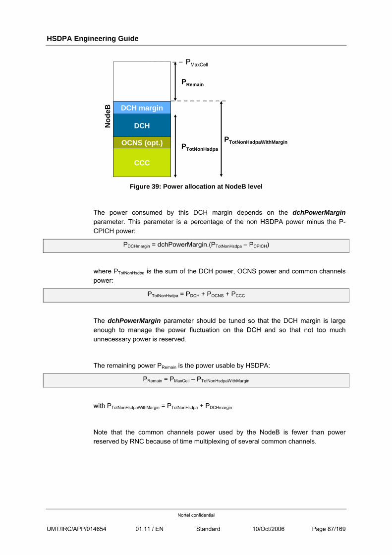
HSDPA Engineering Guide
Nortel confidential
UMT/IRC/APP/014654 01.11 / EN Standard 10/Oct/2006 Page 87/169
CCC
DCH margin
DCHNod
eB
OCNS (opt.) PTotNonHsdpa
PMaxCell
PRemain
PTotNonHsdpaWithMargin
Figure 39: Power allocation at NodeB level
The power consumed by this DCH margin depends on the dchPowerMargin parameter. This parameter is a percentage of the non HSDPA power minus the P-CPICH power:
PDCHmargin = dchPowerMargin.(PTotNonHsdpa – PCPICH)
where PTotNonHsdpa is the sum of the DCH power, OCNS power and common channels power:
PTotNonHsdpa = PDCH + POCNS + PCCC
The dchPowerMargin parameter should be tuned so that the DCH margin is large enough to manage the power fluctuation on the DCH and so that not too much unnecessary power is reserved.
The remaining power PRemain is the power usable by HSDPA:
PRemain = PMaxCell – PTotNonHsdpaWithMargin
with PTotNonHsdpaWithMargin = PTotNonHsdpa + PDCHmargin
Note that the common channels power used by the NodeB is fewer than power reserved by RNC because of time multiplexing of several common channels.
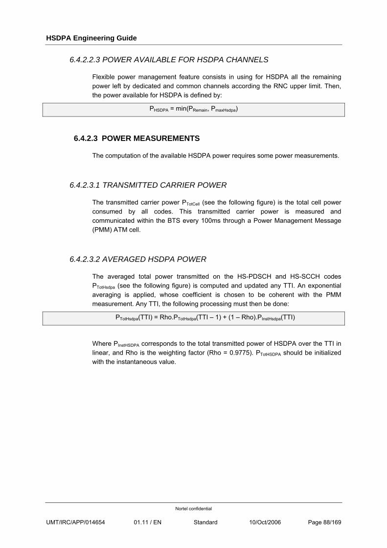
HSDPA Engineering Guide
Nortel confidential
UMT/IRC/APP/014654 01.11 / EN Standard 10/Oct/2006 Page 88/169
6.4.2.2.3 POWER AVAILABLE FOR HSDPA CHANNELS
Flexible power management feature consists in using for HSDPA all the remaining power left by dedicated and common channels according the RNC upper limit. Then, the power available for HSDPA is defined by:
PHSDPA = min(PRemain, PmaxHsdpa)
6.4.2.3 POWER MEASUREMENTS
The computation of the available HSDPA power requires some power measurements.
6.4.2.3.1 TRANSMITTED CARRIER POWER
The transmitted carrier power PTotCell (see the following figure) is the total cell power consumed by all codes. This transmitted carrier power is measured and communicated within the BTS every 100ms through a Power Management Message (PMM) ATM cell.
6.4.2.3.2 AVERAGED HSDPA POWER
The averaged total power transmitted on the HS-PDSCH and HS-SCCH codes PTotHsdpa (see the following figure) is computed and updated any TTI. An exponential averaging is applied, whose coefficient is chosen to be coherent with the PMM measurement. Any TTI, the following processing must then be done:
PTotHsdpa(TTI) = Rho.PTotHsdpa(TTI – 1) + (1 – Rho).PInstHsdpa(TTI)
Where PInstHSDPA corresponds to the total transmitted power of HSDPA over the TTI in linear, and Rho is the weighting factor (Rho = 0.9775). PTotHSDPA should be initialized with the instantaneous value.
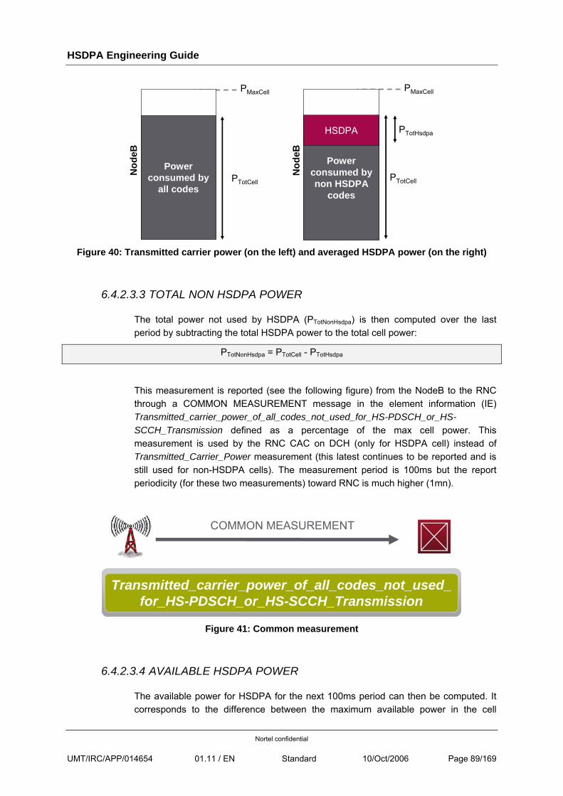
HSDPA Engineering Guide
Nortel confidential
UMT/IRC/APP/014654 01.11 / EN Standard 10/Oct/2006 Page 89/169
Power consumed by
all codes
Nod
eB
PMaxCell
PTotCell
Power consumed by non HSDPA
codes
Nod
eB
PMaxCell
PTotCell
HSDPA PTotHsdpa
Figure 40: Transmitted carrier power (on the left) and averaged HSDPA power (on the right)
6.4.2.3.3 TOTAL NON HSDPA POWER
The total power not used by HSDPA (PTotNonHsdpa) is then computed over the last period by subtracting the total HSDPA power to the total cell power:
PTotNonHsdpa = PTotCell - PTotHsdpa
This measurement is reported (see the following figure) from the NodeB to the RNC through a COMMON MEASUREMENT message in the element information (IE) Transmitted_carrier_power_of_all_codes_not_used_for_HS-PDSCH_or_HS-SCCH_Transmission defined as a percentage of the max cell power. This measurement is used by the RNC CAC on DCH (only for HSDPA cell) instead of Transmitted_Carrier_Power measurement (this latest continues to be reported and is still used for non-HSDPA cells). The measurement period is 100ms but the report periodicity (for these two measurements) toward RNC is much higher (1mn).
COMMON MEASUREMENT
Transmitted_carrier_power_of_all_codes_not_used_for_HS-PDSCH_or_HS-SCCH_Transmission
Figure 41: Common measurement
6.4.2.3.4 AVAILABLE HSDPA POWER
The available power for HSDPA for the next 100ms period can then be computed. It corresponds to the difference between the maximum available power in the cell
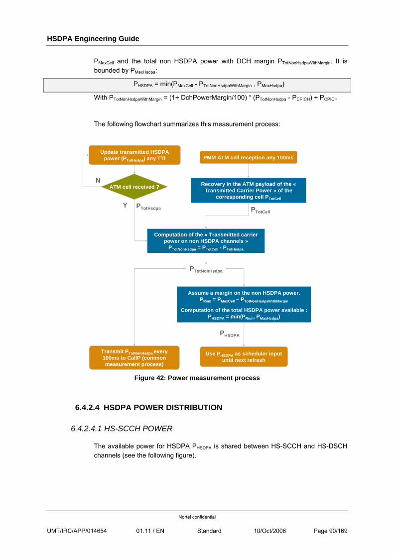
HSDPA Engineering Guide
Nortel confidential
UMT/IRC/APP/014654 01.11 / EN Standard 10/Oct/2006 Page 90/169
PMaxCell and the total non HSDPA power with DCH margin PTotNonHsdpaWithMargin. It is bounded by PMaxHsdpa:
PHSDPA = min(PMaxCell - PTotNonHsdpaWithMargin , PMaxHsdpa)
With PTotNonHsdpaWithMargin = (1+ DchPowerMargin/100) * (PTotNonHsdpa - PCPICH) + PCPICH
The following flowchart summarizes this measurement process:
Update transmitted HSDPA power (PTotHsdpa) any TTI PMM ATM cell reception any 100ms
Y
ATM cell received ? Recovery in the ATM payload of the «Transmitted Carrier Power » of the
corresponding cell PTotCell
N
Computation of the « Transmitted carrier power on non HSDPA channels »
PTotNonHsdpa = PTotCell - PTotHsdpa
PTotCellPTotHsdpa
PTotNonHsdpa
Assume a margin on the non HSDPA power.PRem = PMaxCell – PTotNonHsdpaWithMargin
Computation of the total HSDPA power available :PHSDPA = min(PRem, PMaxHsdpa)
Transmit PTotNonHsdpa every100ms to CallP (commonmeasurement process)
Use PHSDPA as scheduler input until next refresh
PHSDPA
Figure 42: Power measurement process
6.4.2.4 HSDPA POWER DISTRIBUTION
6.4.2.4.1 HS-SCCH POWER
The available power for HSDPA PHSDPA is shared between HS-SCCH and HS-DSCH channels (see the following figure).
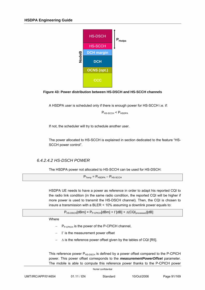
HSDPA Engineering Guide
Nortel confidential
UMT/IRC/APP/014654 01.11 / EN Standard 10/Oct/2006 Page 91/169
CCC
DCH margin
PHsdpa
DCHNod
eB
OCNS (opt.)
HS-DSCH
HS-SCCH
Figure 43: Power distribution between HS-DSCH and HS-SCCH channels
A HSDPA user is scheduled only if there is enough power for HS-SCCH i.e. if:
PHS-SCCH < PHSDPA
If not, the scheduler will try to schedule another user.
The power allocated to HS-SCCH is explained in section dedicated to the feature “HS-SCCH power control”.
6.4.2.4.2 HS-DSCH POWER
The HSDPA power not allocated to HS-SCCH can be used for HS-DSCH:
PTemp = PHSDPA – PHS-SCCH
HSDPA UE needs to have a power as reference in order to adapt his reported CQI to the radio link condition (in the same radio condition, the reported CQI will be higher if more power is used to transmit the HS-DSCH channel). Then, the CQI is chosen to insure a transmission with a BLER < 10% assuming a downlink power equals to:
PHS-DSCH[dBm] = PP-CPICH[dBm] + Γ[dB] + Δ(CQIprocessed)[dB]
Where
− PP-CPICH is the power of the P-CPICH channel,
− Γ is the measurement power offset
− Δ is the reference power offset given by the tables of CQI [R5].
This reference power PHS-DSCH is defined by a power offset compared to the P-CPICH power. This power offset corresponds to the measurementPowerOffset parameter. The mobile is able to compute this reference power thanks to the P-CPICH power
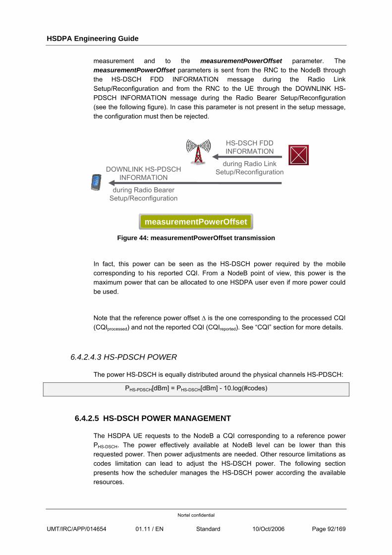
HSDPA Engineering Guide
Nortel confidential
UMT/IRC/APP/014654 01.11 / EN Standard 10/Oct/2006 Page 92/169
measurement and to the measurementPowerOffset parameter. The measurementPowerOffset parameters is sent from the RNC to the NodeB through the HS-DSCH FDD INFORMATION message during the Radio Link Setup/Reconfiguration and from the RNC to the UE through the DOWNLINK HS-PDSCH INFORMATION message during the Radio Bearer Setup/Reconfiguration (see the following figure). In case this parameter is not present in the setup message, the configuration must then be rejected.
DOWNLINK HS-PDSCH INFORMATION
during Radio BearerSetup/Reconfiguration
HS-DSCH FDD INFORMATION
during Radio LinkSetup/Reconfiguration
measurementPowerOffset
Figure 44: measurementPowerOffset transmission
In fact, this power can be seen as the HS-DSCH power required by the mobile corresponding to his reported CQI. From a NodeB point of view, this power is the maximum power that can be allocated to one HSDPA user even if more power could be used.
Note that the reference power offset Δ is the one corresponding to the processed CQI (CQIprocessed) and not the reported CQI (CQIreported). See “CQI” section for more details.
6.4.2.4.3 HS-PDSCH POWER
The power HS-DSCH is equally distributed around the physical channels HS-PDSCH:
PHS-PDSCH[dBm] = PHS-DSCH[dBm] - 10.log(#codes)
6.4.2.5 HS-DSCH POWER MANAGEMENT
The HSDPA UE requests to the NodeB a CQI corresponding to a reference power PHS-DSCH. The power effectively available at NodeB level can be lower than this requested power. Then power adjustments are needed. Other resource limitations as codes limitation can lead to adjust the HS-DSCH power. The following section presents how the scheduler manages the HS-DSCH power according the available resources.
HSDPA Engineering Guide
Nortel confidential
UMT/IRC/APP/014654 01.11 / EN Standard 10/Oct/2006 Page 93/169
6.4.2.6 FIRST TRANSMISSION
The transport formats always remain based on the CQI mapping tables. Two different CQI correspond to different transport formats with the same power to reach the same performance level, but could also correspond to two different powers with the same transport format. A step of 1dB is considered to go from one CQI to the next one.
The transport format is determined according to the processed CQI, CQIprocessed. In case of a lack of resources (codes or power), the applied CQI, CQIapplied, is then modified according to the previous rule to take this into account. It is done in four steps:
• Power limitation management,
• codes limitation management,
• lack of MAC-d PDU in buffer or transport block size limitation (multi-cell per H-BBU for instance),
• optimization of CQI according to MAC-d PDU size.
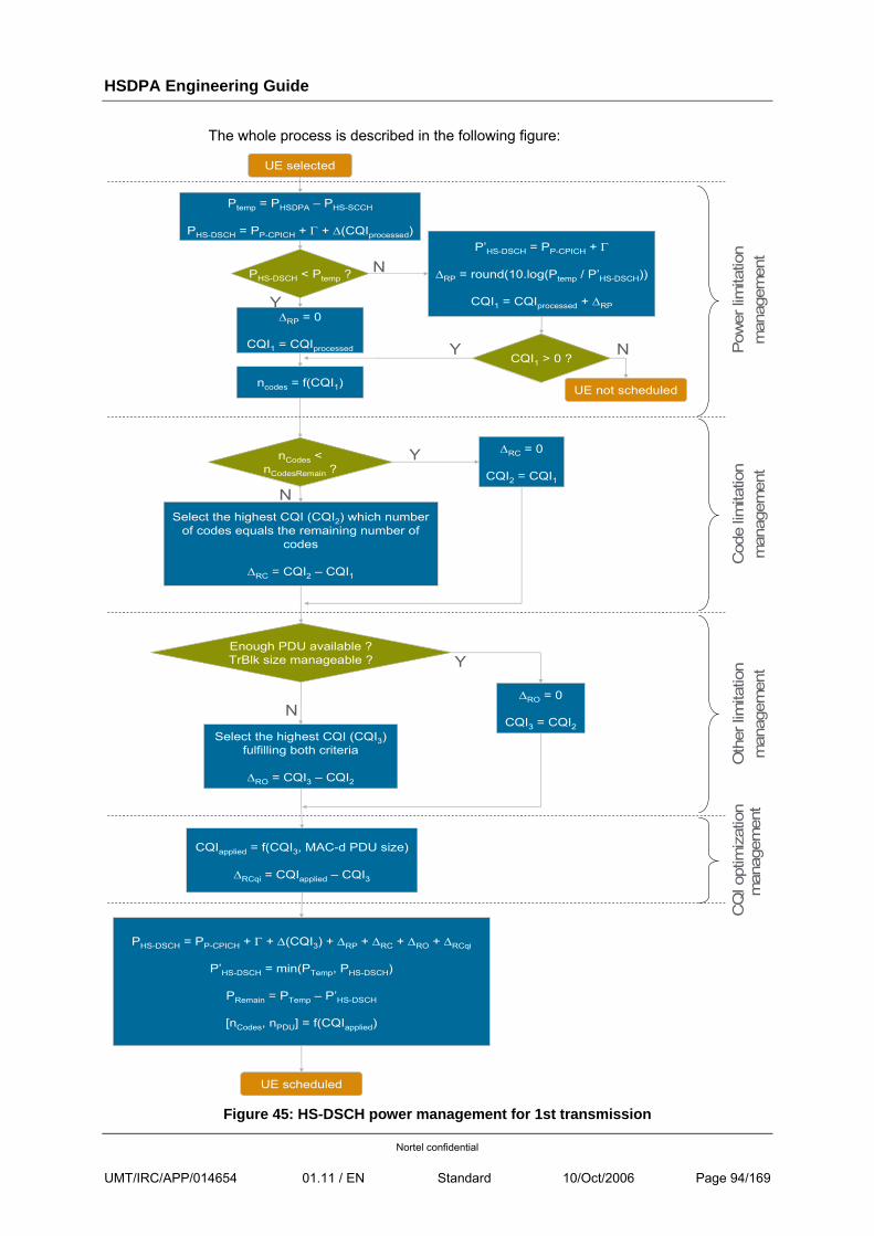
HSDPA Engineering Guide
Nortel confidential
UMT/IRC/APP/014654 01.11 / EN Standard 10/Oct/2006 Page 94/169
The whole process is described in the following figure:
Y
UE selected
Ptemp = PHSDPA – PHS-SCCH
PHS-DSCH = PP-CPICH + Γ + Δ(CQIprocessed)
PHS-DSCH < Ptemp ?
P’HS-DSCH = PP-CPICH + Γ
ΔRP = round(10.log(Ptemp / P’HS-DSCH))
CQI1 = CQIprocessed + ΔRPΔRP = 0
CQI1 = CQIprocessedCQI1 > 0 ?
ncodes = f(CQI1) UE not scheduled
Y
N
N
YnCodes < nCodesRemain ?
Select the highest CQI (CQI2) which numberof codes equals the remaining number of
codes
ΔRC = CQI2 – CQI1
N
ΔRC = 0
CQI2 = CQI1
Enough PDU available ? TrBlk size manageable ?
Select the highest CQI (CQI3) fulfilling both criteria
ΔRO = CQI3 – CQI2
NΔRO = 0
CQI3 = CQI2
Y
CQIapplied = f(CQI3, MAC-d PDU size)
ΔRCqi = CQIapplied – CQI3
PHS-DSCH = PP-CPICH + Γ + Δ(CQI3) + ΔRP + ΔRC + ΔRO + ΔRCqi
P’HS-DSCH = min(PTemp, PHS-DSCH)
PRemain = PTemp – P’HS-DSCH
[nCodes, nPDU] = f(CQIapplied)
UE scheduled
Pow
er li
mita
tion
man
agem
ent
Cod
e lim
itatio
nm
anag
emen
tO
ther
limita
tion
man
agem
ent
CQ
I opt
imiz
atio
nm
anag
emen
t
Figure 45: HS-DSCH power management for 1st transmission
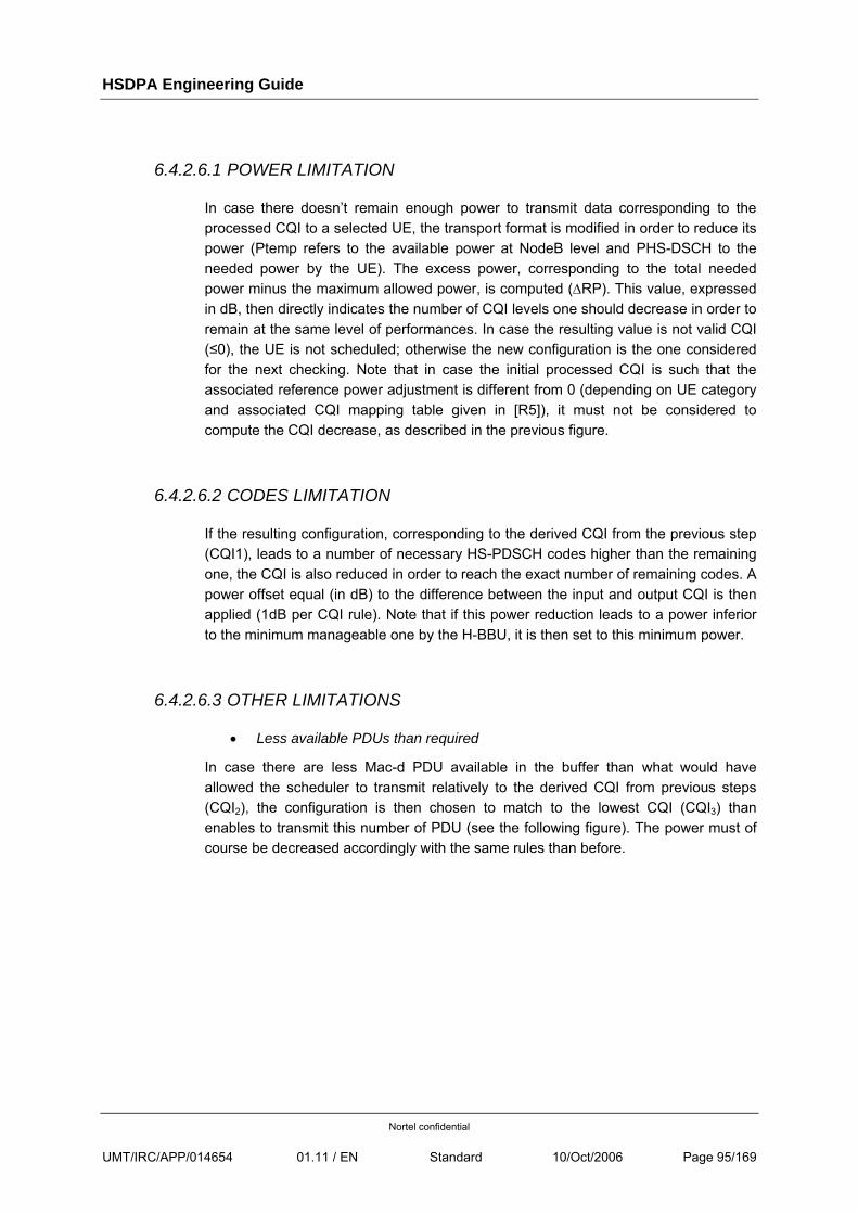
HSDPA Engineering Guide
Nortel confidential
UMT/IRC/APP/014654 01.11 / EN Standard 10/Oct/2006 Page 95/169
6.4.2.6.1 POWER LIMITATION
In case there doesn’t remain enough power to transmit data corresponding to the processed CQI to a selected UE, the transport format is modified in order to reduce its power (Ptemp refers to the available power at NodeB level and PHS-DSCH to the needed power by the UE). The excess power, corresponding to the total needed power minus the maximum allowed power, is computed (ΔRP). This value, expressed in dB, then directly indicates the number of CQI levels one should decrease in order to remain at the same level of performances. In case the resulting value is not valid CQI (≤0), the UE is not scheduled; otherwise the new configuration is the one considered for the next checking. Note that in case the initial processed CQI is such that the associated reference power adjustment is different from 0 (depending on UE category and associated CQI mapping table given in [R5]), it must not be considered to compute the CQI decrease, as described in the previous figure.
6.4.2.6.2 CODES LIMITATION
If the resulting configuration, corresponding to the derived CQI from the previous step (CQI1), leads to a number of necessary HS-PDSCH codes higher than the remaining one, the CQI is also reduced in order to reach the exact number of remaining codes. A power offset equal (in dB) to the difference between the input and output CQI is then applied (1dB per CQI rule). Note that if this power reduction leads to a power inferior to the minimum manageable one by the H-BBU, it is then set to this minimum power.
6.4.2.6.3 OTHER LIMITATIONS
• Less available PDUs than required
In case there are less Mac-d PDU available in the buffer than what would have allowed the scheduler to transmit relatively to the derived CQI from previous steps (CQI2), the configuration is then chosen to match to the lowest CQI (CQI3) than enables to transmit this number of PDU (see the following figure). The power must of course be decreased accordingly with the same rules than before.
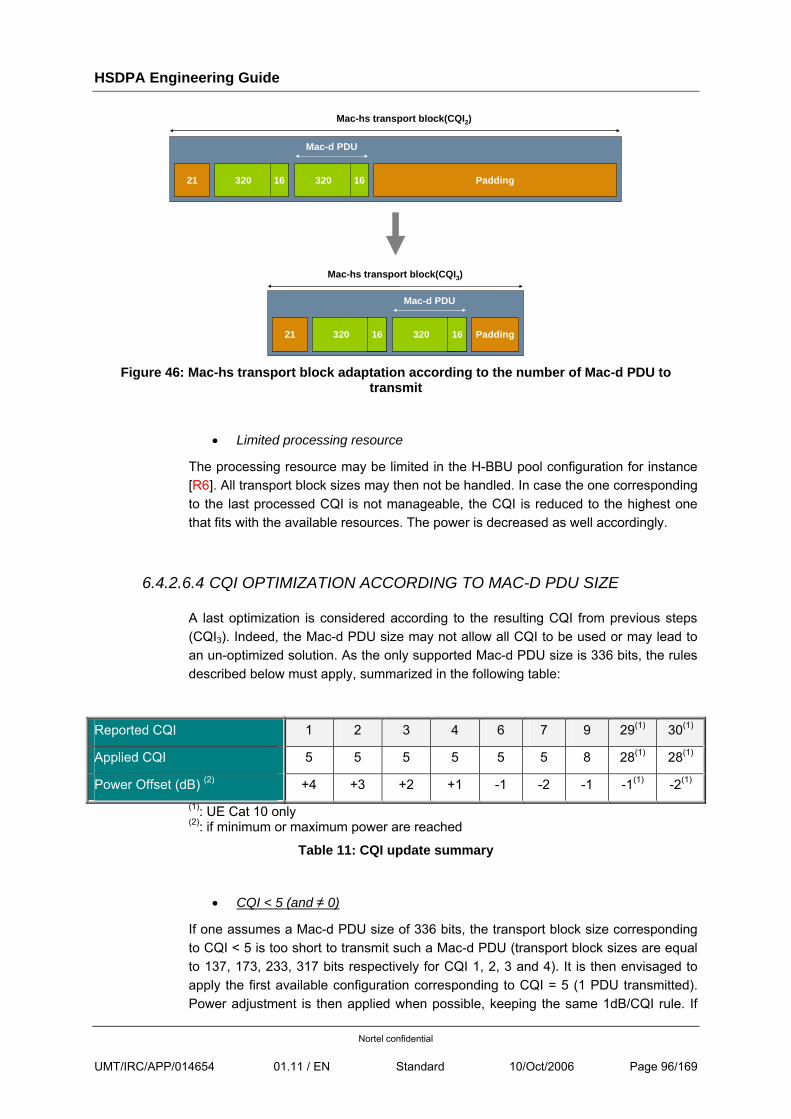
HSDPA Engineering Guide
Nortel confidential
UMT/IRC/APP/014654 01.11 / EN Standard 10/Oct/2006 Page 96/169
320 1621 Padding
Mac-d PDU
Mac-hs transport block(CQI2)
320 16
320 1621 Padding
Mac-d PDU
Mac-hs transport block(CQI3)
320 16
Figure 46: Mac-hs transport block adaptation according to the number of Mac-d PDU to
transmit
• Limited processing resource
The processing resource may be limited in the H-BBU pool configuration for instance [R6]. All transport block sizes may then not be handled. In case the one corresponding to the last processed CQI is not manageable, the CQI is reduced to the highest one that fits with the available resources. The power is decreased as well accordingly.
6.4.2.6.4 CQI OPTIMIZATION ACCORDING TO MAC-D PDU SIZE
A last optimization is considered according to the resulting CQI from previous steps (CQI3). Indeed, the Mac-d PDU size may not allow all CQI to be used or may lead to an un-optimized solution. As the only supported Mac-d PDU size is 336 bits, the rules described below must apply, summarized in the following table:
Reported CQI 1 2 3 4 6 7 9 29(1) 30(1)
Applied CQI 5 5 5 5 5 5 8 28(1) 28(1)
Power Offset (dB) (2) +4 +3 +2 +1 -1 -2 -1 -1(1) -2(1) (1): UE Cat 10 only (2): if minimum or maximum power are reached
Table 11: CQI update summary
• CQI < 5 (and ≠ 0)
If one assumes a Mac-d PDU size of 336 bits, the transport block size corresponding to CQI < 5 is too short to transmit such a Mac-d PDU (transport block sizes are equal to 137, 173, 233, 317 bits respectively for CQI 1, 2, 3 and 4). It is then envisaged to apply the first available configuration corresponding to CQI = 5 (1 PDU transmitted). Power adjustment is then applied when possible, keeping the same 1dB/CQI rule. If
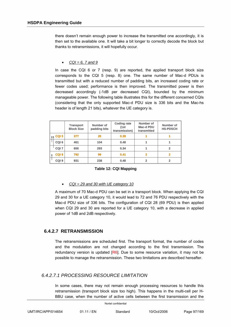
HSDPA Engineering Guide
Nortel confidential
UMT/IRC/APP/014654 01.11 / EN Standard 10/Oct/2006 Page 97/169
there doesn’t remain enough power to increase the transmitted one accordingly, it is then set to the available one. It will take a bit longer to correctly decode the block but thanks to retransmissions, it will hopefully occur.
• CQI = 6, 7 and 9
In case the CQI 6 or 7 (resp. 9) are reported, the applied transport block size corresponds to the CQI 5 (resp. 8) one. The same number of Mac-d PDUs is transmitted but with a reduced number of padding bits, an increased coding rate or fewer codes used; performance is then improved. The transmitted power is then decreased accordingly (-1dB per decreased CQI), bounded by the minimum manageable power. The following table illustrates this for the different concerned CQIs (considering that the only supported Mac-d PDU size is 336 bits and the Mac-hs header is of length 21 bits), whatever the UE category is.
210.34293650CQI 7
220.4199792CQI 8
220.48238931CQI 9
110.48104461CQI 6
110.3920377CQI 5
Number ofHS-PDSCH
Number ofMac-d PDU transmitted
Coding rate (1st
transmission)
Number ofpadding bits
Transport Block Size
210.34293650CQI 7
220.4199792CQI 8
220.48238931CQI 9
110.48104461CQI 6
110.3920377CQI 5
Number ofHS-PDSCH
Number ofMac-d PDU transmitted
Coding rate (1st
transmission)
Number ofpadding bits
Transport Block Size
Table 12: CQI Mapping
• CQI = 29 and 30 with UE category 10
A maximum of 70 Mac-d PDU can be set in a transport block. When applying the CQI 29 and 30 for a UE category 10, it would lead to 72 and 76 PDU respectively with the Mac-d PDU size of 336 bits. The configuration of CQI 28 (69 PDU) is then applied when CQI 29 and 30 are reported for a UE category 10, with a decrease in applied power of 1dB and 2dB respectively.
6.4.2.7 RETRANSMISSION
The retransmissions are scheduled first. The transport format, the number of codes and the modulation are not changed according to the first transmission. The redundancy version is updated [R6]. Due to some resource variation, it may not be possible to manage the retransmission. These two limitations are described hereafter.
6.4.2.7.1 PROCESSING RESOURCE LIMITATION
In some cases, there may not remain enough processing resources to handle this retransmission (transport block size too high). This happens in the multi-cell per H-BBU case, when the number of active cells between the first transmission and the
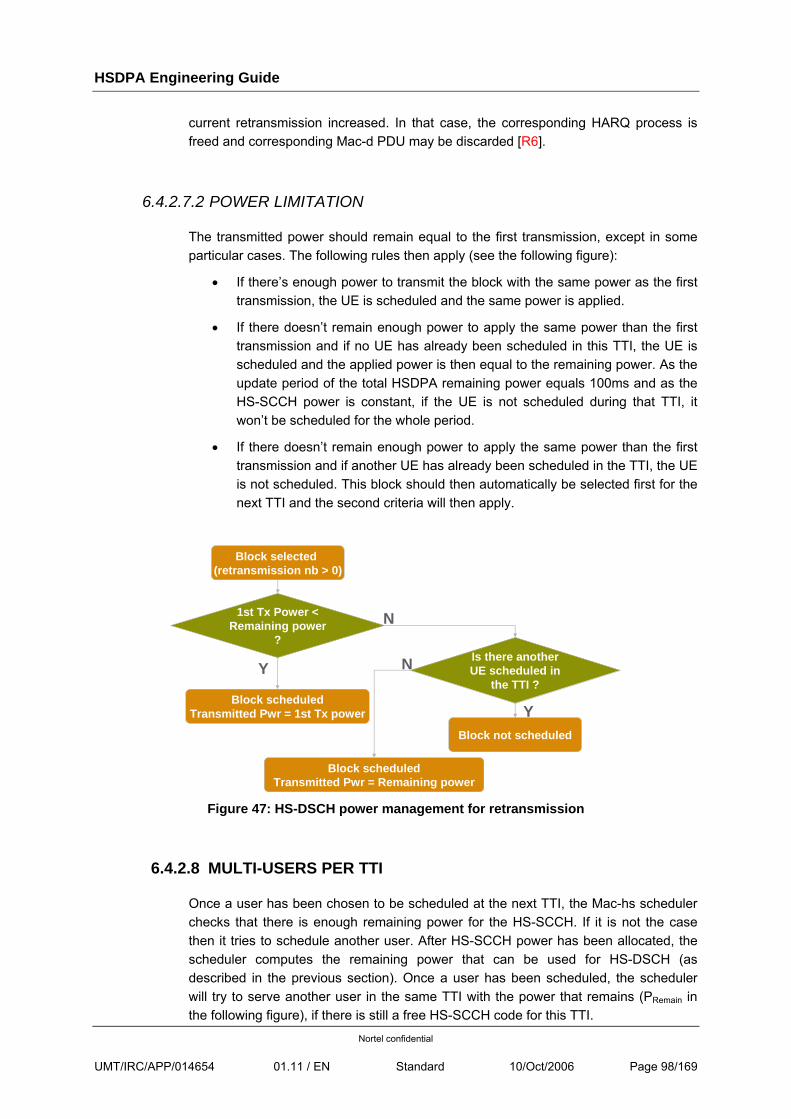
HSDPA Engineering Guide
Nortel confidential
UMT/IRC/APP/014654 01.11 / EN Standard 10/Oct/2006 Page 98/169
current retransmission increased. In that case, the corresponding HARQ process is freed and corresponding Mac-d PDU may be discarded [R6].
6.4.2.7.2 POWER LIMITATION
The transmitted power should remain equal to the first transmission, except in some particular cases. The following rules then apply (see the following figure):
• If there’s enough power to transmit the block with the same power as the first transmission, the UE is scheduled and the same power is applied.
• If there doesn’t remain enough power to apply the same power than the first transmission and if no UE has already been scheduled in this TTI, the UE is scheduled and the applied power is then equal to the remaining power. As the update period of the total HSDPA remaining power equals 100ms and as the HS-SCCH power is constant, if the UE is not scheduled during that TTI, it won’t be scheduled for the whole period.
• If there doesn’t remain enough power to apply the same power than the first transmission and if another UE has already been scheduled in the TTI, the UE is not scheduled. This block should then automatically be selected first for the next TTI and the second criteria will then apply.
Y
Block selected(retransmission nb > 0)
1st Tx Power < Remaining power
?N
Block scheduledTransmitted Pwr = 1st Tx power
Is there anotherUE scheduled in
the TTI ?
Block scheduledTransmitted Pwr = Remaining power
Block not scheduled
Y
N
Figure 47: HS-DSCH power management for retransmission
6.4.2.8 MULTI-USERS PER TTI
Once a user has been chosen to be scheduled at the next TTI, the Mac-hs scheduler checks that there is enough remaining power for the HS-SCCH. If it is not the case then it tries to schedule another user. After HS-SCCH power has been allocated, the scheduler computes the remaining power that can be used for HS-DSCH (as described in the previous section). Once a user has been scheduled, the scheduler will try to serve another user in the same TTI with the power that remains (PRemain in the following figure), if there is still a free HS-SCCH code for this TTI.
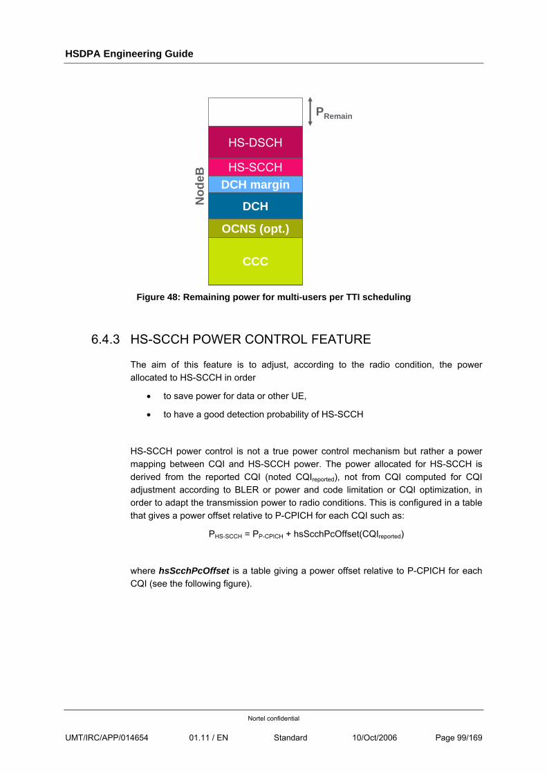
HSDPA Engineering Guide
Nortel confidential
UMT/IRC/APP/014654 01.11 / EN Standard 10/Oct/2006 Page 99/169
CCC
DCH margin
PRemain
DCHNod
eB
OCNS (opt.)
HS-DSCH
HS-SCCH
Figure 48: Remaining power for multi-users per TTI scheduling
6.4.3 HS-SCCH POWER CONTROL FEATURE
The aim of this feature is to adjust, according to the radio condition, the power allocated to HS-SCCH in order
• to save power for data or other UE,
• to have a good detection probability of HS-SCCH
HS-SCCH power control is not a true power control mechanism but rather a power mapping between CQI and HS-SCCH power. The power allocated for HS-SCCH is derived from the reported CQI (noted CQIreported), not from CQI computed for CQI adjustment according to BLER or power and code limitation or CQI optimization, in order to adapt the transmission power to radio conditions. This is configured in a table that gives a power offset relative to P-CPICH for each CQI such as:
PHS-SCCH = PP-CPICH + hsScchPcOffset(CQIreported)
where hsScchPcOffset is a table giving a power offset relative to P-CPICH for each CQI (see the following figure).
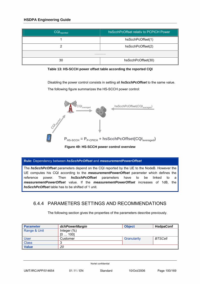
HSDPA Engineering Guide
Nortel confidential
UMT/IRC/APP/014654 01.11 / EN Standard 10/Oct/2006 Page 100/169
CQIreported hsScchPcOffset relativ to PCPICH Power
1 hsScchPcOffset(1)
2 hsScchPcOffset(2)
……….
30 hsScchPcOffset(30)
Table 13: HS-SCCH power offset table according the reported CQI
Disabling the power control consists in setting all hsScchPcOffset to the same value.
The following figure summarizes the HS-SCCH power control:
CQI repo
rted
PHS-SCCH = PP-CPICH + hsScchPcOffset(CQIaveraged)
CQIaveraged hsScchPcOffset(CQIaveraged)
Figure 49: HS-SCCH power control overview
Rule: Dependency between hsScchPcOffset and measurementPowerOffset
The hsScchPcOffset parameters depend on the CQI reported by the UE to the NodeB. However the UE computes his CQI according to the measurementPowerOffset parameter which defines the reference power. Then hsScchPcOffset parameters have to be linked to a measurementPowerOffset value. If the measurementPowerOffset increases of 1dB, the hsScchPcOffset table has to be shifted of 1 unit.
6.4.4 PARAMETERS SETTINGS AND RECOMMENDATIONS
The following section gives the properties of the parameters describe previously.
Parameter dchPowerMargin Object HsdpaConf Range & Unit Integer (%)
[0 … 100] User Customer Class 3
Granularity BTSCell
Value 20
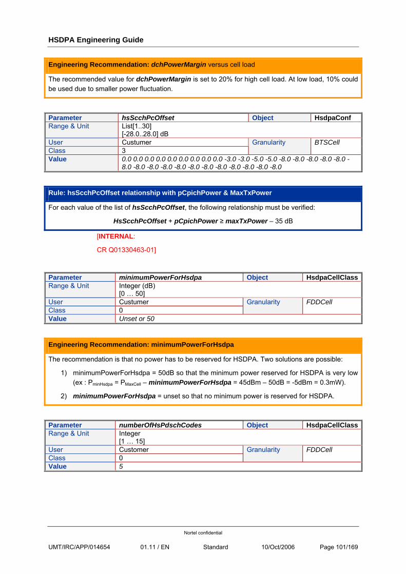
HSDPA Engineering Guide
Nortel confidential
UMT/IRC/APP/014654 01.11 / EN Standard 10/Oct/2006 Page 101/169
Engineering Recommendation: dchPowerMargin versus cell load
The recommended value for dchPowerMargin is set to 20% for high cell load. At low load, 10% could be used due to smaller power fluctuation.
Parameter hsScchPcOffset Object HsdpaConf Range & Unit List[1..30]
[-28.0..28.0] dB User Custumer Class 3
Granularity BTSCell
Value 0.0 0.0 0.0 0.0 0.0 0.0 0.0 0.0 0.0 -3.0 -3.0 -5.0 -5.0 -8.0 -8.0 -8.0 -8.0 -8.0 -8.0 -8.0 -8.0 -8.0 -8.0 -8.0 -8.0 -8.0 -8.0 -8.0 -8.0 -8.0
Rule: hsScchPcOffset relationship with pCpichPower & MaxTxPower
For each value of the list of hsScchPcOffset, the following relationship must be verified:
HsScchPcOffset + pCpichPower ≥ maxTxPower – 35 dB
[INTERNAL:
CR Q01330463-01]
Parameter minimumPowerForHsdpa Object HsdpaCellClassRange & Unit Integer (dB)
[0 … 50] User Custumer Class 0
Granularity FDDCell
Value Unset or 50
Engineering Recommendation: minimumPowerForHsdpa
The recommendation is that no power has to be reserved for HSDPA. Two solutions are possible:
1) minimumPowerForHsdpa = 50dB so that the minimum power reserved for HSDPA is very low (ex : PminHsdpa = PMaxCell – minimumPowerForHsdpa = 45dBm – 50dB = -5dBm = 0.3mW).
2) minimumPowerForHsdpa = unset so that no minimum power is reserved for HSDPA.
Parameter numberOfHsPdschCodes Object HsdpaCellClassRange & Unit Integer
[1 … 15] User Customer Class 0
Granularity FDDCell
Value 5
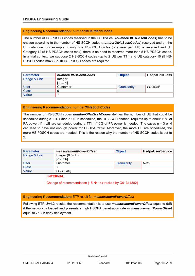
HSDPA Engineering Guide
Nortel confidential
UMT/IRC/APP/014654 01.11 / EN Standard 10/Oct/2006 Page 102/169
Engineering Recommendation: numberOfHsPdschCodes
The number of HS-PDSCH codes reserved in the HSDPA cell (numberOfHsPdschCodes) has to be chosen according to the number of HS-SCCH codes (numberOfHsScchCodes) reserved and on the UE categorie. For example, if only one HS-SCCH codes (one user per TTI) is reserved and UE Category 12 (5 HS-PDSCH codes max), there is no need to reserved more than 5 HS-PDSCH codes. In a trial context, we suppose 2 HS-SCCH codes (up to 2 UE per TTI) and UE category 10 (5 HS-PDSCH codes max). So 10 HS-PDSCH codes are required.
Parameter numberOfHsScchCodes Object HsdpaCellClassRange & Unit Integer
[1 … 4] User Customer Class 0
Granularity FDDCell
Value 1
Engineering Recommendation: numberOfHsScchCodes
The number of HS-SCCH codes numberOfHsScchCodes defines the number of UE that could be scheduled during a TTI. When a UE is scheduled, the HS-SCCH channel requires up to about 10% of PA power. If n UE are scheduled during a TTI, n*10% of PA power is needed. The cases n = 3 or 4 can lead to have not enough power for HSDPA traffic. Moreover, the more UE are scheduled, the more HS-PDSCH codes are needed. This is the reason why the number of HS-SCCH codes is set to 2.
Parameter measurementPowerOffset Object HsdpaUserServiceRange & Unit Integer (0.5 dB)
[-12..26] User Customer Class 3
Granularity RNC
Value 14 (=7 dB) [INTERNAL:
Change of recommendation (15 14) tracked by Q01314882]
Engineering Recommendation: ETP result for measurementPowerOffset
Following ETP UA4.2 results, the recommendation is to use measurementPowerOffset equal to 6dB if the network is loaded and presents a high HSDPA penetration rate or measurementPowerOffset equal to 7dB in early deployment.
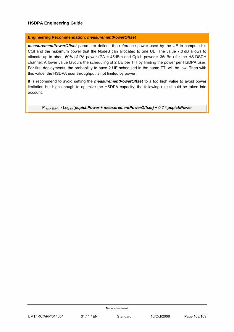
HSDPA Engineering Guide
Nortel confidential
UMT/IRC/APP/014654 01.11 / EN Standard 10/Oct/2006 Page 103/169
Engineering Recommendation: measurementPowerOffset
measurementPowerOffset parameter defines the reference power used by the UE to compute his CQI and the maximum power that the NodeB can allocated to one UE. The value 7.0 dB allows to allocate up to about 60% of PA power (PA = 45dBm and Cpich power = 35dBm) for the HS-DSCH channel. A lower value favours the scheduling of 2 UE per TTI by limiting the power per HSDPA user. For first deployments, the probability to have 2 UE scheduled in the same TTI will be low. Then with this value, the HSDPA user throughput is not limited by power.
It is recommend to avoid setting the measurementPowerOffset to a too high value to avoid power limitation but high enough to optimize the HSDPA capacity, the following rule should be taken into account:
PmaxHSDPA > Log2lin(pcpichPower + measurementPowerOffset) + 0.7 * pcpichPower
HSDPA Engineering Guide
Nortel confidential
UMT/IRC/APP/014654 01.11 / EN Standard 10/Oct/2006 Page 104/169
6.5 TRANSPORT
6.5.1 IU USER TRAFFIC CONFORMANCE
For HS-DSCH traffic, the RNC implements a traffic conformance mechanism on the Iu interface to ensure that the user traffic never exceeds the maximum bit rate negotiated at RAB establishment. This is only applicable in downlink.
This mechanism is optional and can be activated at RNC level (applicable to HSDPA Service).
6.5.1.1 FEATURE DESCRIPTION
In UA4.2, an HSDPA RAB is allocated if:
• the primary cell supports HSDPA
And
• the UE is HSDPA capable (sent on RRC connection Setup Complete: if R5 UE then is HSDPA capable)
And
• the UE is requesting Interactive or Background Service.
The HSDPA DL channel is given regardless of the MaxBitRate in the Core RAB
A R5 UE user that has a subscription in the HLR of MaxBitRate=64K or 384K or 2M will be given with the same HSDPA DL channel and will benefit of throughputs up to 1.2M ( UE cat12)
If a subscriber (whatever MaxBitRate in HLR) inserts its SIM into a HSDPA UE , it will have access to a throughput that is only limited by the UE ( cat12=>1.4Megs, cat6=>3.4Megs)
When activated, RNC source conformance traffic feature monitors the user traffic on IU and deletes the traffic above:
• Core MaxBitRate given on the RAB so that negotiated QOS at Core establishment is not exceeded
• RNC Parameter that is an absolute threshold
6.5.1.2 ALGORITHM
This capability is based on a token bucket algorithm as specified in [R13].
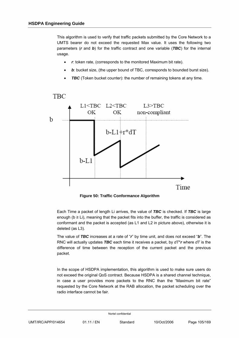
HSDPA Engineering Guide
Nortel confidential
UMT/IRC/APP/014654 01.11 / EN Standard 10/Oct/2006 Page 105/169
This algorithm is used to verify that traffic packets submitted by the Core Network to a UMTS bearer do not exceed the requested Max value. It uses the following two parameters (r and b) for the traffic contract and one variable (TBC) for the internal usage.
• r: token rate, (corresponds to the monitored Maximum bit rate).
• b: bucket size, (the upper bound of TBC, corresponds to bounded burst size).
• TBC (Token bucket counter): the number of remaining tokens at any time.
Figure 50: Traffic Conformance Algorithm
Each Time a packet of length Li arrives, the value of TBC is checked. If TBC is large enough (b ≥ Li), meaning that the packet fits into the buffer, the traffic is considered as conformant and the packet is accepted (as L1 and L2 in picture above), otherwise it is deleted (as L3).
The value of TBC increases at a rate of “r” by time unit, and does not exceed “b”. The RNC will actually updates TBC each time it receives a packet, by dT*r where dT is the difference of time between the reception of the current packet and the previous packet.
In the scope of HSDPA implementation, this algorithm is used to make sure users do not exceed the original QoS contract. Because HSDPA is a shared channel technique, in case a user provides more packets to the RNC than the “Maximum bit rate” requested by the Core Network at the RAB allocation, the packet scheduling over the radio interface cannot be fair.
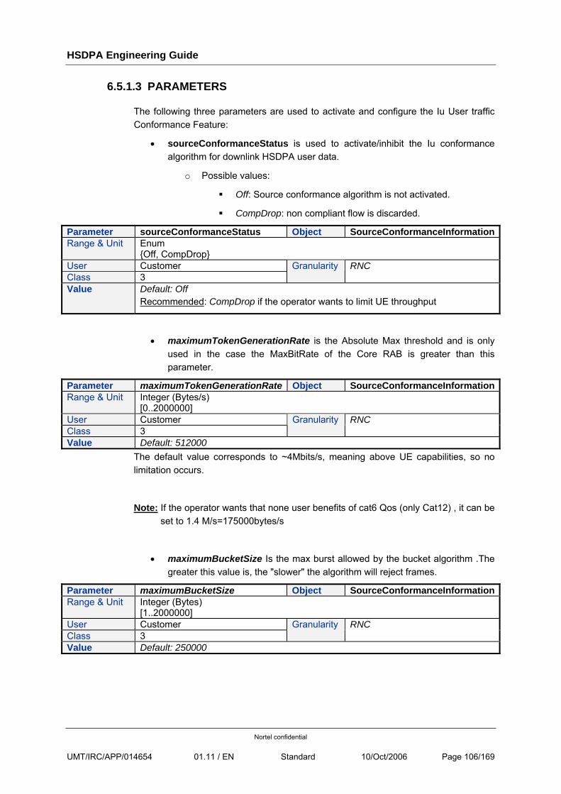
HSDPA Engineering Guide
Nortel confidential
UMT/IRC/APP/014654 01.11 / EN Standard 10/Oct/2006 Page 106/169
6.5.1.3 PARAMETERS
The following three parameters are used to activate and configure the Iu User traffic Conformance Feature:
• sourceConformanceStatus is used to activate/inhibit the Iu conformance algorithm for downlink HSDPA user data.
o Possible values:
Off: Source conformance algorithm is not activated.
CompDrop: non compliant flow is discarded.
Parameter sourceConformanceStatus Object SourceConformanceInformationRange & Unit Enum
{Off, CompDrop} User Customer Class 3
Granularity RNC
Value Default: Off Recommended: CompDrop if the operator wants to limit UE throughput
• maximumTokenGenerationRate is the Absolute Max threshold and is only used in the case the MaxBitRate of the Core RAB is greater than this parameter.
Parameter maximumTokenGenerationRate Object SourceConformanceInformationRange & Unit Integer (Bytes/s)
[0..2000000] User Customer Class 3
Granularity RNC
Value Default: 512000 The default value corresponds to ~4Mbits/s, meaning above UE capabilities, so no limitation occurs.
Note: If the operator wants that none user benefits of cat6 Qos (only Cat12) , it can be set to 1.4 M/s=175000bytes/s
• maximumBucketSize Is the max burst allowed by the bucket algorithm .The greater this value is, the "slower" the algorithm will reject frames.
Parameter maximumBucketSize Object SourceConformanceInformationRange & Unit Integer (Bytes)
[1..2000000] User Customer Class 3
Granularity RNC
Value Default: 250000
HSDPA Engineering Guide
Nortel confidential
UMT/IRC/APP/014654 01.11 / EN Standard 10/Oct/2006 Page 107/169
Engineering Recommendation: maximumBucketSize
The higher the value, the larger the burst allowed and the better performance is noticed by a UE making burstly traffic.
To limit PS 384k users, this parameters shall be set according to:
maximumBucketSize = 2 * max UE throughput * 1 sec
maximumBucketSize = 96000bytes for limiting PS384K users
6.5.1.4 FEATURE BEHAVIOUR
The feature monitors each user throughput and deletes IU SDUs that overpass threshold given Core RAB or RNC provisioned absolute threshold
When Sequence Number loss is detected, TCP layer slows down (reduces window) so that sender throughput is decreased.
HSDPA subscribers will have access to the full UE Cat12 throughput when in HSDPA cell. If the HSDPA subscriber goes into R99 area it has PS384K R99 channel.
Provisioning to be changed: The Downlink MaxBitRate in the HLR needs increased for HSDPA subscribers to 1.4 Megs (case cat12 and 3.4M if cat6 is allowed)
R99 subscribers keep their MaxBitRate to 384K in HLR. A R99 subscriber using a HSDPA capable UE in a HSDPA cell will have a HSDPA channel being limited to 384K throughput (value from Core RAB)
6.5.2 IUB BANDWIDTH LIMITATION
6.5.2.1 WHY THIS FEATURE IS NEEDED?
6.5.2.1.1 BEFORE UA4.2: IUB CONGESTION IS CONTROLLED BY AAL2 CAC.
• Case of DS traffic:
The RB activity is more or less constant and predictable. Therefore EBR can be set properly and call admission control is enough to manage Iub congestion in an efficient way.
• Case of NDS traffic:
The RB activity is not constant and very unpredictable, due to the diversity of applications (ftp, streaming, web, email, etc.). Therefore it is very difficult to control Iub congestion at call admission with a deterministic cost per RB.
The efficient control of Iub congestion via AAL2 CAC requires to set very conservative EBR, which means a lot of call rejections and a small Iub usage.
HSDPA Engineering Guide
Nortel confidential
UMT/IRC/APP/014654 01.11 / EN Standard 10/Oct/2006 Page 108/169
Settings aggressive EBRs provides acceptable Iub capacity but potentially huge Iub congestion: peaks of NDS traffic increase delays spent in ATM buffers. When delays become high, the DCHFPs are received late (hence are lost and BLER increases). When the congestion increases, ATM buffer are full. The loss of ATM cells causes also the loss of DCHFPs. The combination of BLER increase and delay increase causes RLC window to stall. From an end to end point of view, the increase of delays causes TCP to slow down. As a result, the end user perception is bad (small throughput) and the Iub usage not optimal
6.5.2.1.2 IN UA4.2: INTRODUCTION OF NEW HSDPA FLOW
The introduction of HSDPA increases the Iub congestion problems due to the huge throughput (up to 3.4Mbit/s at RLC) per user. Also the credits allocated by the NodeB (capacity allocation) are based on the RF conditions and do not take into account Iub. If the Iub bandwidth is small compared to the RF capacity, bursts of traffic higher than Iub bandwidth can be sent even by a single user (note: 1 UE cat 6 at 3.4Mbit/s requires 2.3E1).
Note that AAL2 CAC does not regulate HSDPA like NDS: HSDPA are not CACed with EBR but on a max number of HSDPA users.
6.5.2.1.3 GOAL OF IUB BANDWIDTH LIMITATION
It controls Iub congestion thanks to the regulation of the DL PDUs received in excess at the RNC side. This regulation works for NDS and HSDPA.
6.5.2.2 FEATURE DESCRIPTION
A continuous monitoring of DS, NDS and HSDPA traffic in DL at FP level is done by the PMC PC. The feature works with thresholds, which represent the peak of traffic allowed on Iub:
• 2 Discard thresholds: Th1 for DS+NDS and Th2 for DS+NDS+HSDPA
o When DS+NDS reach Th1, NDS FPs are deleted by PMC PC.
o When DS+NDS+HSDPA reaches Th2, HSDPA FPs are deleted by PMC PC.
• 2 Back Pressure thresholds: Xoff1 for NDS and Xoff2 for HSDPA (eg. Xoffi=95% Thi)
o When DS+NDS reaches Xoff1, PMC PC ask PMC RAB to stop transmission of NDS FPs during Txoff1
o When DS+NDS+HSDPA reaches Xoff2, PMC PC ask PMC RAB to stop transmission of HSDPA FPs during Txoff2
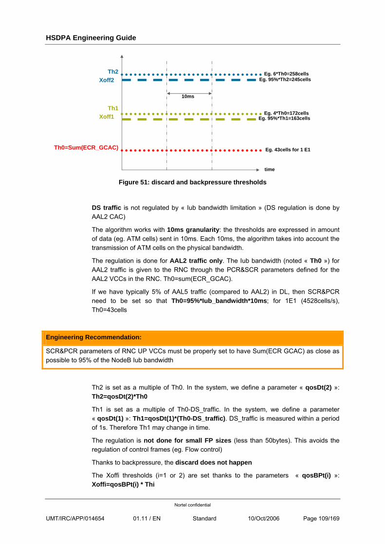
HSDPA Engineering Guide
Nortel confidential
UMT/IRC/APP/014654 01.11 / EN Standard 10/Oct/2006 Page 109/169
Th0=Sum(ECR_GCAC)
Th1Xoff1
Th2 Xoff2
10ms
Eg. 43cells for 1 E1
Eg. 4*Th0=172cells
Eg. 6*Th0=258cellsEg. 95%*Th2=245cells
Eg. 95%*Th1=163cells
time Figure 51: discard and backpressure thresholds
DS traffic is not regulated by « Iub bandwidth limitation » (DS regulation is done by AAL2 CAC)
The algorithm works with 10ms granularity: the thresholds are expressed in amount of data (eg. ATM cells) sent in 10ms. Each 10ms, the algorithm takes into account the transmission of ATM cells on the physical bandwidth.
The regulation is done for AAL2 traffic only. The Iub bandwidth (noted « Th0 ») for AAL2 traffic is given to the RNC through the PCR&SCR parameters defined for the AAL2 VCCs in the RNC. Th0=sum(ECR_GCAC).
If we have typically 5% of AAL5 traffic (compared to AAL2) in DL, then SCR&PCR need to be set so that Th0=95%*Iub_bandwidth*10ms; for 1E1 (4528cells/s), Th0=43cells
Engineering Recommendation:
SCR&PCR parameters of RNC UP VCCs must be properly set to have Sum(ECR GCAC) as close as possible to 95% of the NodeB Iub bandwidth
Th2 is set as a multiple of Th0. In the system, we define a parameter « qosDt(2) »: Th2=qosDt(2)*Th0
Th1 is set as a multiple of Th0-DS_traffic. In the system, we define a parameter « qosDt(1) »: Th1=qosDt(1)*(Th0-DS_traffic). DS_traffic is measured within a period of 1s. Therefore Th1 may change in time.
The regulation is not done for small FP sizes (less than 50bytes). This avoids the regulation of control frames (eg. Flow control)
Thanks to backpressure, the discard does not happen
The Xoffi thresholds (i=1 or 2) are set thanks to the parameters « qosBPt(i) »: Xoffi=qosBPt(i) * Thi
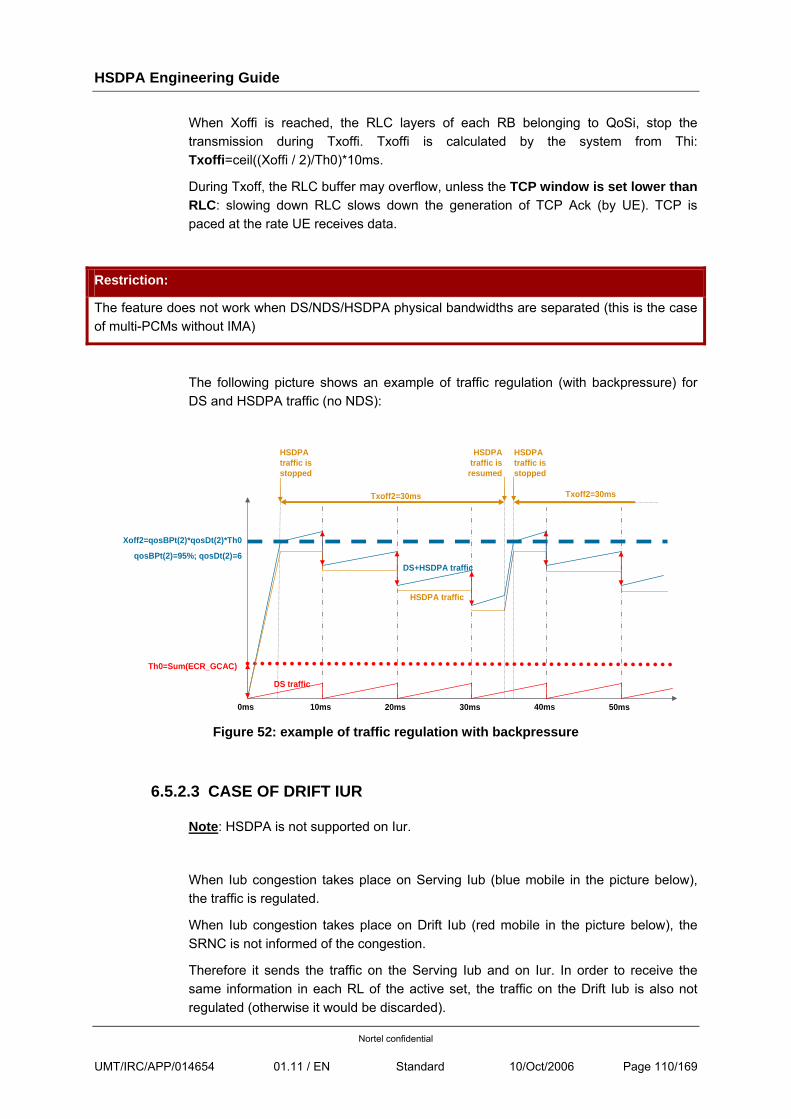
HSDPA Engineering Guide
Nortel confidential
UMT/IRC/APP/014654 01.11 / EN Standard 10/Oct/2006 Page 110/169
When Xoffi is reached, the RLC layers of each RB belonging to QoSi, stop the transmission during Txoffi. Txoffi is calculated by the system from Thi: Txoffi=ceil((Xoffi / 2)/Th0)*10ms.
During Txoff, the RLC buffer may overflow, unless the TCP window is set lower than RLC: slowing down RLC slows down the generation of TCP Ack (by UE). TCP is paced at the rate UE receives data.
Restriction:
The feature does not work when DS/NDS/HSDPA physical bandwidths are separated (this is the case of multi-PCMs without IMA)
The following picture shows an example of traffic regulation (with backpressure) for DS and HSDPA traffic (no NDS):
Th0=Sum(ECR_GCAC)
Xoff2=qosBPt(2)*qosDt(2)*Th0
qosBPt(2)=95%; qosDt(2)=6
Txoff2=30ms
DS traffic
HSDPA traffic
DS+HSDPA traffic
HSDPA traffic is stopped
HSDPA traffic is
resumed
Txoff2=30ms
HSDPA traffic is stopped
10ms 20ms 30ms 40ms 50ms0ms Figure 52: example of traffic regulation with backpressure
6.5.2.3 CASE OF DRIFT IUR
Note: HSDPA is not supported on Iur.
When Iub congestion takes place on Serving Iub (blue mobile in the picture below), the traffic is regulated.
When Iub congestion takes place on Drift Iub (red mobile in the picture below), the SRNC is not informed of the congestion.
Therefore it sends the traffic on the Serving Iub and on Iur. In order to receive the same information in each RL of the active set, the traffic on the Drift Iub is also not regulated (otherwise it would be discarded).
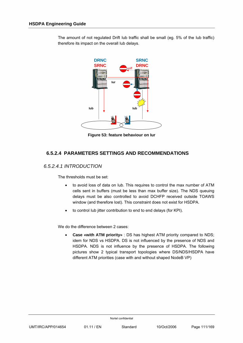
HSDPA Engineering Guide
Nortel confidential
UMT/IRC/APP/014654 01.11 / EN Standard 10/Oct/2006 Page 111/169
The amount of not regulated Drift Iub traffic shall be small (eg. 5% of the Iub traffic) therefore its impact on the overall Iub delays.
SRNC DRNC
Iub Iub
Iur
SRNCDRNC
xoff
Figure 53: feature behaviour on Iur
6.5.2.4 PARAMETERS SETTINGS AND RECOMMENDATIONS
6.5.2.4.1 INTRODUCTION
The thresholds must be set:
• to avoid loss of data on Iub. This requires to control the max number of ATM cells sent in buffers (must be less than max buffer size). The NDS queuing delays must be also controlled to avoid DCHFP received outside TOAWS window (and therefore lost). This constraint does not exist for HSDPA.
• to control Iub jitter contribution to end to end delays (for KPI).
We do the difference between 2 cases:
• Case «with ATM priority» : DS has highest ATM priority compared to NDS; idem for NDS vs HSDPA. DS is not influenced by the presence of NDS and HSDPA. NDS is not influence by the presence of HSDPA. The following pictures show 2 typical transport topologies where DS/NDS/HSDPA have different ATM priorities (case with and without shaped NodeB VP)
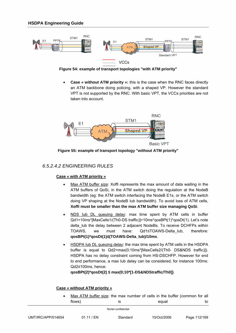
HSDPA Engineering Guide
Nortel confidential
UMT/IRC/APP/014654 01.11 / EN Standard 10/Oct/2006 Page 112/169
STM1E1 PP7K
RNCSTM1E1 PP7K
RNCSTM1
Shaped VPATM
E1 PP7KRNC
STM1
Standard VPT
STM1
Shaped VPATM
E1 PP7KRNC
STM1
Standard VPT VCCs
Figure 54: example of transport topologies "with ATM priority"
• Case « without ATM priority »: this is the case when the RNC faces directly an ATM backbone doing policing, with a shaped VP. However the standard VPT is not supported by the RNC. With basic VPT, the VCCs priorities are not taken into account.
STM1
Shaped VPATM
E1
RNC
Basic VPT
STM1
Shaped VPATM
E1
RNC
Basic VPT
Figure 55: example of transport topology "without ATM priority"
6.5.2.4.2 ENGINEERING RULES
Case « with ATM priority »
• Max ATM buffer size: Xoffi represents the max amount of data waiting in the ATM buffers of QoSi, in the ATM switch doing the regulation at the NodeB bandwidth (eg: the ATM switch interfacing the NodeB E1s, or the ATM switch doing VP shaping at the NodeB Iub bandwidth). To avoid loss of ATM cells, Xoffi must be smaller than the max ATM buffer size managing QoSi.
• NDS Iub DL queuing delay: max time spent by ATM cells in buffer Qd1=10ms*[MaxCells1/(Th0-DS traffic)]=10ms*qosBPt(1)*qosDt(1). Let’s note delta_Iub the delay between 2 adjacent NodeBs. To receive DCHFPs within TOAWS, we must have: Qd1≤TOAWS-Delta_Iub, therefore: qosBPt(1)*qosDt(1)≤(TOAWS-Delta_Iub)/10ms.
• HSDPA Iub DL queuing delay: the max time spent by ATM cells in the HSDPA buffer is equal to Qd2=max(0;10ms*[MaxCells2/(Th0- DS&NDS traffic)]). HSDPA has no delay constraint coming from HS-DSCHFP. However for end to end performance, a max Iub delay can be considered, for instance 100ms: Qd2≤100ms, hence: qosBPt(2)*qosDt(2) ≤ max(0;10*[1-DS&NDStraffic/Th0]).
Case « without ATM priority »
• Max ATM buffer size: the max number of cells in the buffer (common for all flows) is equal to
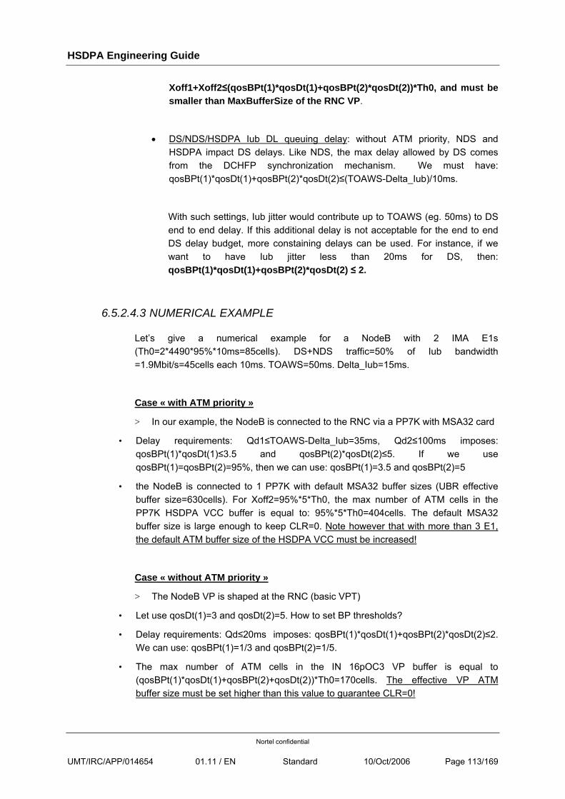
HSDPA Engineering Guide
Nortel confidential
UMT/IRC/APP/014654 01.11 / EN Standard 10/Oct/2006 Page 113/169
Xoff1+Xoff2≤(qosBPt(1)*qosDt(1)+qosBPt(2)*qosDt(2))*Th0, and must be smaller than MaxBufferSize of the RNC VP.
• DS/NDS/HSDPA Iub DL queuing delay: without ATM priority, NDS and HSDPA impact DS delays. Like NDS, the max delay allowed by DS comes from the DCHFP synchronization mechanism. We must have: qosBPt(1)*qosDt(1)+qosBPt(2)*qosDt(2)≤(TOAWS-Delta_Iub)/10ms.
With such settings, Iub jitter would contribute up to TOAWS (eg. 50ms) to DS end to end delay. If this additional delay is not acceptable for the end to end DS delay budget, more constaining delays can be used. For instance, if we want to have Iub jitter less than 20ms for DS, then: qosBPt(1)*qosDt(1)+qosBPt(2)*qosDt(2) ≤ 2.
6.5.2.4.3 NUMERICAL EXAMPLE
Let’s give a numerical example for a NodeB with 2 IMA E1s (Th0=2*4490*95%*10ms=85cells). DS+NDS traffic=50% of Iub bandwidth =1.9Mbit/s=45cells each 10ms. TOAWS=50ms. Delta_Iub=15ms.
Case « with ATM priority »
> In our example, the NodeB is connected to the RNC via a PP7K with MSA32 card
• Delay requirements: Qd1≤TOAWS-Delta_Iub=35ms, Qd2≤100ms imposes: qosBPt(1)*qosDt(1)≤3.5 and qosBPt(2)*qosDt(2)≤5. If we use qosBPt(1)=qosBPt(2)=95%, then we can use: qosBPt(1)=3.5 and qosBPt(2)=5
• the NodeB is connected to 1 PP7K with default MSA32 buffer sizes (UBR effective buffer size=630cells). For Xoff2=95%*5*Th0, the max number of ATM cells in the PP7K HSDPA VCC buffer is equal to: 95%*5*Th0=404cells. The default MSA32 buffer size is large enough to keep CLR=0. Note however that with more than 3 E1, the default ATM buffer size of the HSDPA VCC must be increased!
Case « without ATM priority »
> The NodeB VP is shaped at the RNC (basic VPT)
• Let use qosDt(1)=3 and qosDt(2)=5. How to set BP thresholds?
• Delay requirements: Qd≤20ms imposes: qosBPt(1)*qosDt(1)+qosBPt(2)*qosDt(2)≤2. We can use: qosBPt(1)=1/3 and qosBPt(2)=1/5.
• The max number of ATM cells in the IN 16pOC3 VP buffer is equal to (qosBPt(1)*qosDt(1)+qosBPt(2)+qosDt(2))*Th0=170cells. The effective VP ATM buffer size must be set higher than this value to guarantee CLR=0!
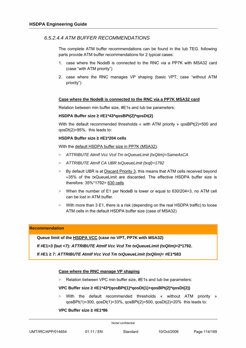
HSDPA Engineering Guide
Nortel confidential
UMT/IRC/APP/014654 01.11 / EN Standard 10/Oct/2006 Page 114/169
6.5.2.4.4 ATM BUFFER RECOMMENDATIONS
The complete ATM buffer recommendations can be found in the Iub TEG. following parts provide ATM buffer recommendations for 2 typical cases:
1. case where the NodeB is connected to the RNC via a PP7K with MSA32 card (case “with ATM priority”)
2. case where the RNC manages VP shaping (basic VPT; case “without ATM priority”)
Case where the NodeB is connected to the RNC via a PP7K MSA32 card
Relation between min buffer size, #E1s and Iub bw parameters:
HSDPA Buffer size ≥ #E1*43*qosBPt(2)*qosDt(2)
With the default recommended thresholds « with ATM priority » qosBPt(2)=500 and qosDt(2)=95%, this leads to:
HSDPA Buffer size ≥ #E1*204 cells
With the default HSDPA buffer size in PP7K (MSA32):
> ATTRIBUTE AtmIf Vcc Vcd Tm txQueueLimit (txQlim)=SameAsCA
> ATTRIBUTE AtmIf CA UBR txQueueLimit (txql)=1792
> By default UBR is at Discard Priority 3, this means that ATM cells received beyond ≈35% of the txQueueLimit are discarded. The effective HSDPA buffer size is therefore: 35%*1792= 630 cells
> When the number of E1 per NodeB is lower or equal to 630/204=3, no ATM cell can be lost in ATM buffer.
> With more than 3 E1, there is a risk (depending on the real HSDPA traffic) to loose ATM cells in the default HSDPA buffer size (case of MSA32)
Recommendation
Queue limit of the HSDPA VCC (case no VPT, PP7K with MSA32)
If #E1>3 (but <7): ATTRIBUTE AtmIf Vcc Vcd Tm txQueueLimit (txQlim)=2*1792.
If #E1 ≥ 7: ATTRIBUTE AtmIf Vcc Vcd Tm txQueueLimit (txQlim)= #E1*583
Case where the RNC manage VP shaping
> Relation between VPC min buffer size, #E1s and Iub bw parameters:
VPC Buffer size ≥ #E1*43*(qosBPt(1)*qosDt(1)+qosBPt(2)*qosDt(2))
> With the default recommended thresholds « without ATM priority » qosBPt(1)=300, qosDt(1)=33%, qosBPt(2)=500, qosDt(2)=20% this leads to:
VPC Buffer size ≥ #E1*86
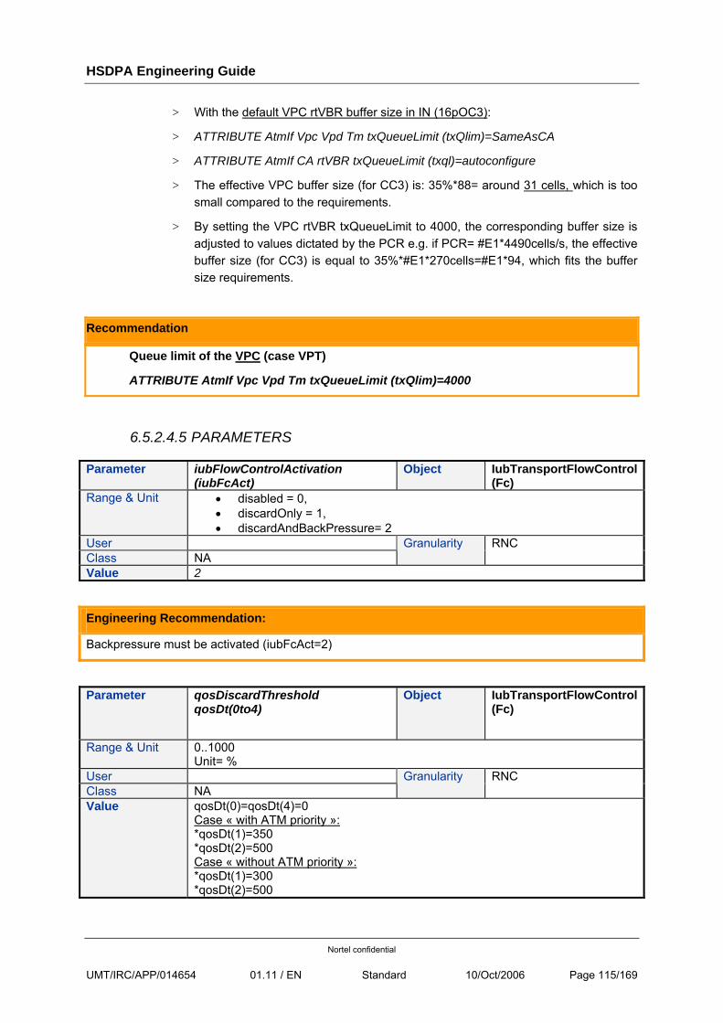
HSDPA Engineering Guide
Nortel confidential
UMT/IRC/APP/014654 01.11 / EN Standard 10/Oct/2006 Page 115/169
> With the default VPC rtVBR buffer size in IN (16pOC3):
> ATTRIBUTE AtmIf Vpc Vpd Tm txQueueLimit (txQlim)=SameAsCA
> ATTRIBUTE AtmIf CA rtVBR txQueueLimit (txql)=autoconfigure
> The effective VPC buffer size (for CC3) is: 35%*88= around 31 cells, which is too small compared to the requirements.
> By setting the VPC rtVBR txQueueLimit to 4000, the corresponding buffer size is adjusted to values dictated by the PCR e.g. if PCR= #E1*4490cells/s, the effective buffer size (for CC3) is equal to 35%*#E1*270cells=#E1*94, which fits the buffer size requirements.
Recommendation
Queue limit of the VPC (case VPT)
ATTRIBUTE AtmIf Vpc Vpd Tm txQueueLimit (txQlim)=4000
6.5.2.4.5 PARAMETERS
Parameter iubFlowControlActivation (iubFcAct)
Object IubTransportFlowControl(Fc)
Range & Unit • disabled = 0, • discardOnly = 1, • discardAndBackPressure= 2
User Class NA
Granularity RNC
Value 2
Engineering Recommendation:
Backpressure must be activated (iubFcAct=2)
Parameter qosDiscardThreshold qosDt(0to4)
Object IubTransportFlowControl(Fc)
Range & Unit 0..1000 Unit= %
User Class NA
Granularity RNC
Value qosDt(0)=qosDt(4)=0 Case « with ATM priority »: *qosDt(1)=350 *qosDt(2)=500 Case « without ATM priority »: *qosDt(1)=300 *qosDt(2)=500
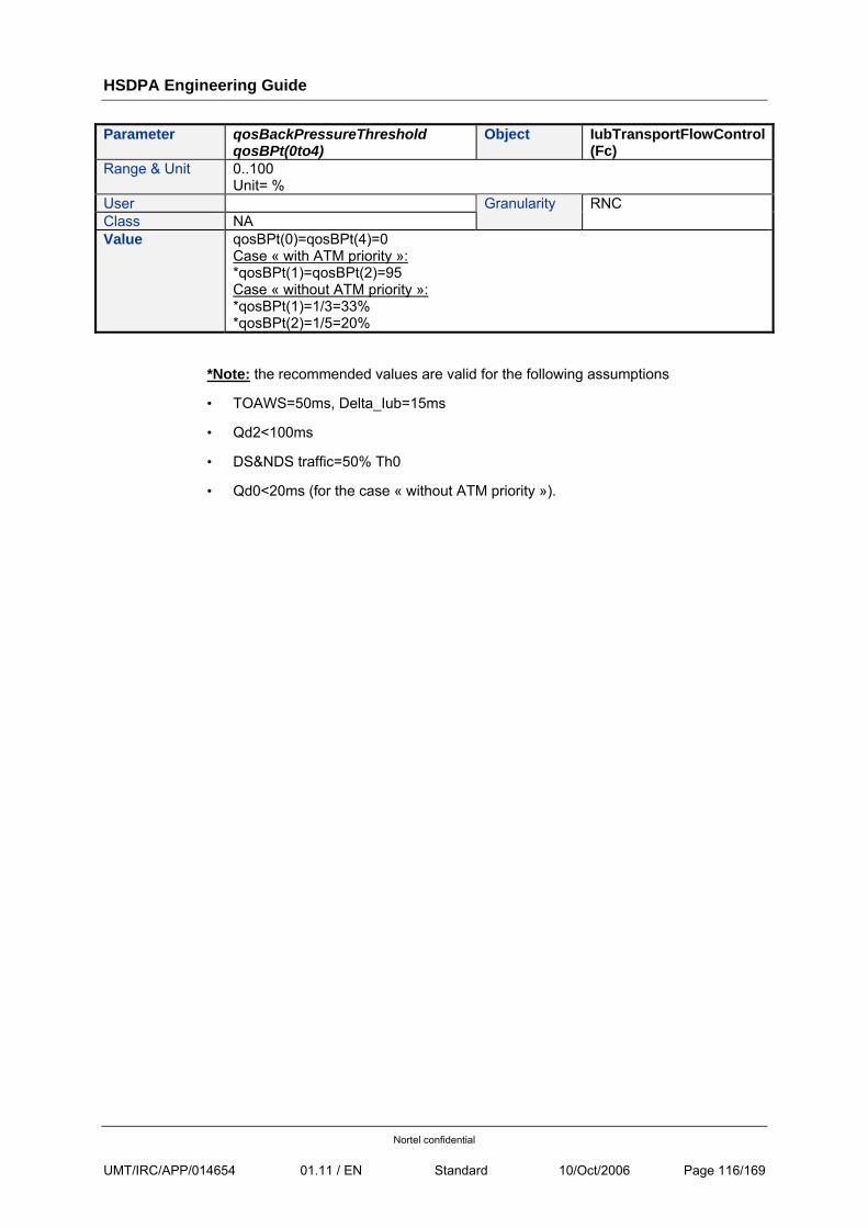
HSDPA Engineering Guide
Nortel confidential
UMT/IRC/APP/014654 01.11 / EN Standard 10/Oct/2006 Page 116/169
Parameter qosBackPressureThreshold qosBPt(0to4)
Object IubTransportFlowControl(Fc)
Range & Unit 0..100 Unit= %
User Class NA
Granularity RNC
Value qosBPt(0)=qosBPt(4)=0 Case « with ATM priority »: *qosBPt(1)=qosBPt(2)=95 Case « without ATM priority »: *qosBPt(1)=1/3=33% *qosBPt(2)=1/5=20%
*Note: the recommended values are valid for the following assumptions
• TOAWS=50ms, Delta_Iub=15ms
• Qd2<100ms
• DS&NDS traffic=50% Th0
• Qd0<20ms (for the case « without ATM priority »).
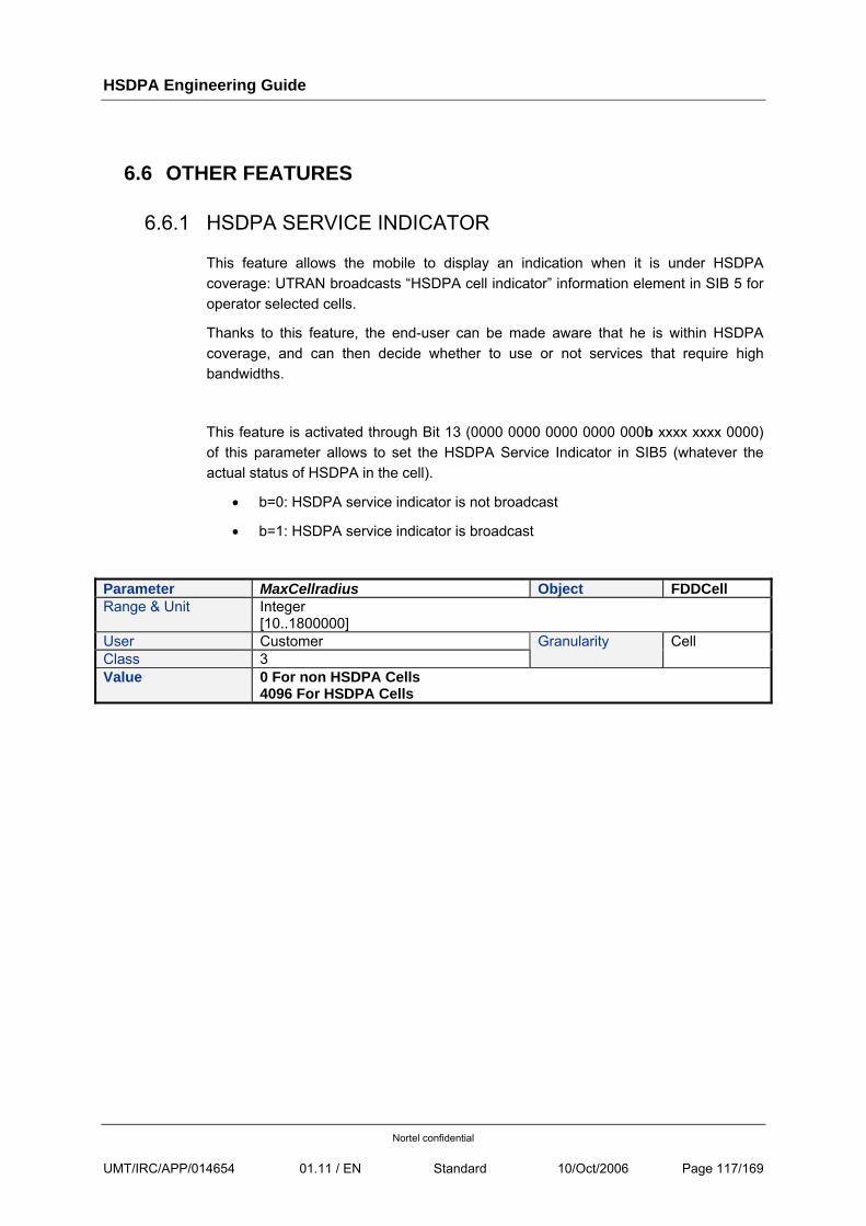
HSDPA Engineering Guide
Nortel confidential
UMT/IRC/APP/014654 01.11 / EN Standard 10/Oct/2006 Page 117/169
6.6 OTHER FEATURES
6.6.1 HSDPA SERVICE INDICATOR
This feature allows the mobile to display an indication when it is under HSDPA coverage: UTRAN broadcasts “HSDPA cell indicator” information element in SIB 5 for operator selected cells.
Thanks to this feature, the end-user can be made aware that he is within HSDPA coverage, and can then decide whether to use or not services that require high bandwidths.
This feature is activated through Bit 13 (0000 0000 0000 0000 000b xxxx xxxx 0000) of this parameter allows to set the HSDPA Service Indicator in SIB5 (whatever the actual status of HSDPA in the cell).
• b=0: HSDPA service indicator is not broadcast
• b=1: HSDPA service indicator is broadcast
Parameter MaxCellradius Object FDDCell Range & Unit Integer
[10..1800000] User Customer Class 3
Granularity Cell
Value 0 For non HSDPA Cells 4096 For HSDPA Cells
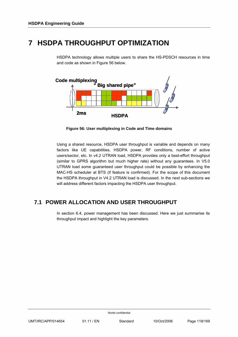
HSDPA Engineering Guide
Nortel confidential
UMT/IRC/APP/014654 01.11 / EN Standard 10/Oct/2006 Page 118/169
7 HSDPA THROUGHPUT OPTIMIZATION
HSDPA technology allows multiple users to share the HS-PDSCH resources in time and code as shown in Figure 56 below.
Figure 56: User multiplexing in Code and Time domains
Using a shared resource, HSDPA user throughput is variable and depends on many factors like UE capabilities, HSDPA power, RF conditions, number of active users/sector, etc. In v4.2 UTRAN load, HSDPA provides only a best-effort throughput (similar to GPRS algorithm but much higher rate) without any guarantees. In V5.0 UTRAN load some guaranteed user throughput could be possible by enhancing the MAC-HS scheduler at BTS (if feature is confirmed). For the scope of this document the HSDPA throughput in V4.2 UTRAN load is discussed. In the next sub-sections we will address different factors impacting the HSDPA user throughput.
7.1 POWER ALLOCATION AND USER THROUGHPUT
In section 6.4, power management has been discussed. Here we just summarise its throughput impact and highlight the key parameters.
Code multiplexing
HSDPA2ms
“ “ Big shared pipeBig shared pipe””Code multiplexing
HSDPA2ms
“ “ Big shared pipeBig shared pipe””
2ms
“ “ Big shared pipeBig shared pipe””
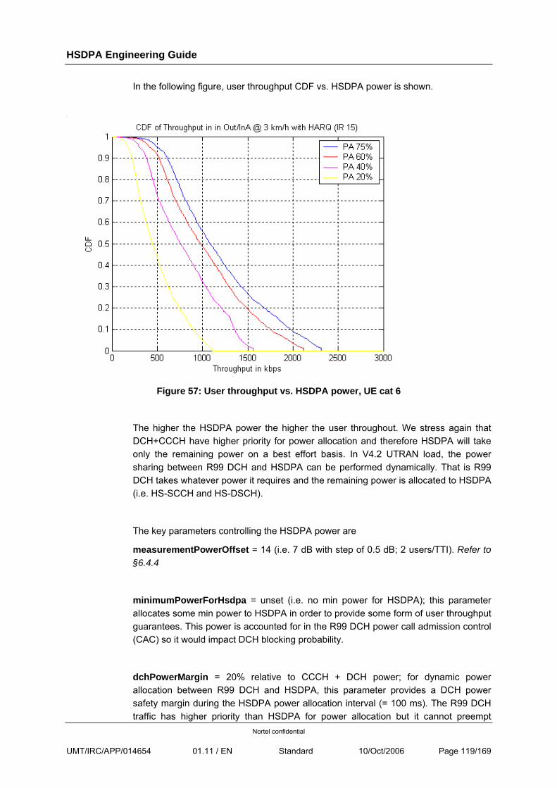
HSDPA Engineering Guide
Nortel confidential
UMT/IRC/APP/014654 01.11 / EN Standard 10/Oct/2006 Page 119/169
In the following figure, user throughput CDF vs. HSDPA power is shown.
Figure 57: User throughput vs. HSDPA power, UE cat 6
The higher the HSDPA power the higher the user throughout. We stress again that DCH+CCCH have higher priority for power allocation and therefore HSDPA will take only the remaining power on a best effort basis. In V4.2 UTRAN load, the power sharing between R99 DCH and HSDPA can be performed dynamically. That is R99 DCH takes whatever power it requires and the remaining power is allocated to HSDPA (i.e. HS-SCCH and HS-DSCH).
The key parameters controlling the HSDPA power are
measurementPowerOffset = 14 (i.e. 7 dB with step of 0.5 dB; 2 users/TTI). Refer to §6.4.4
minimumPowerForHsdpa = unset (i.e. no min power for HSDPA); this parameter allocates some min power to HSDPA in order to provide some form of user throughput guarantees. This power is accounted for in the R99 DCH power call admission control (CAC) so it would impact DCH blocking probability.
dchPowerMargin = 20% relative to CCCH + DCH power; for dynamic power allocation between R99 DCH and HSDPA, this parameter provides a DCH power safety margin during the HSDPA power allocation interval (= 100 ms). The R99 DCH traffic has higher priority than HSDPA for power allocation but it cannot preempt
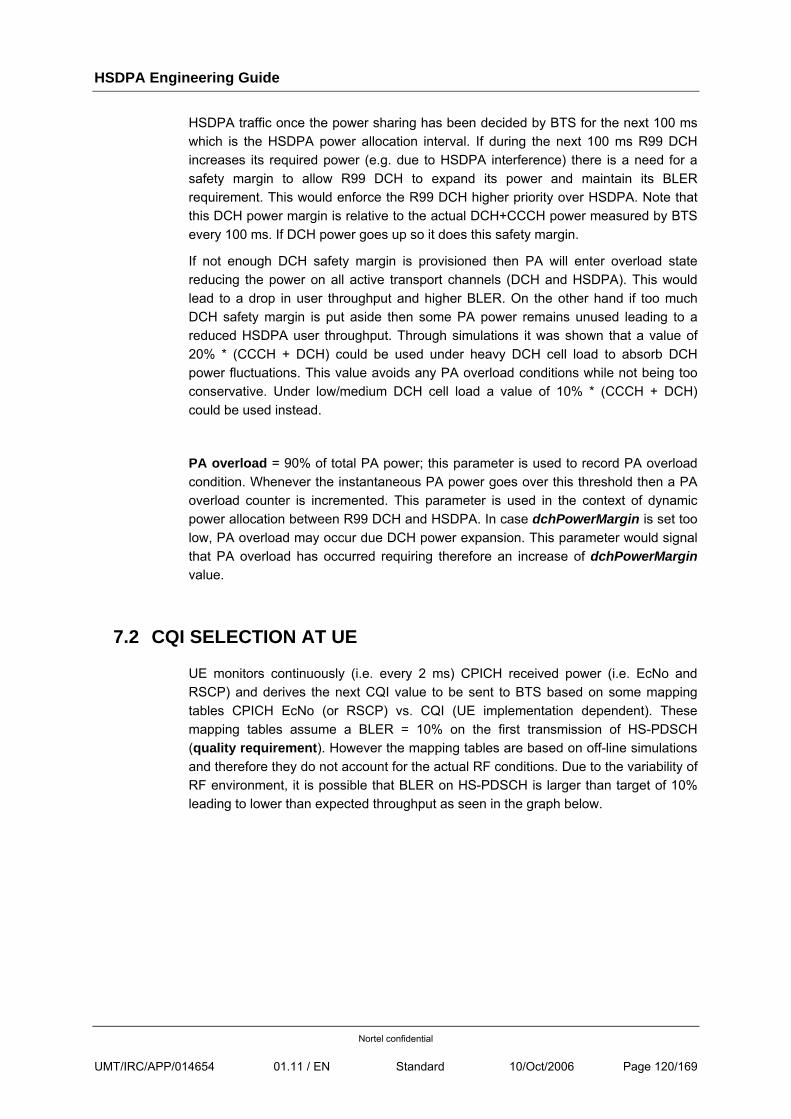
HSDPA Engineering Guide
Nortel confidential
UMT/IRC/APP/014654 01.11 / EN Standard 10/Oct/2006 Page 120/169
HSDPA traffic once the power sharing has been decided by BTS for the next 100 ms which is the HSDPA power allocation interval. If during the next 100 ms R99 DCH increases its required power (e.g. due to HSDPA interference) there is a need for a safety margin to allow R99 DCH to expand its power and maintain its BLER requirement. This would enforce the R99 DCH higher priority over HSDPA. Note that this DCH power margin is relative to the actual DCH+CCCH power measured by BTS every 100 ms. If DCH power goes up so it does this safety margin.
If not enough DCH safety margin is provisioned then PA will enter overload state reducing the power on all active transport channels (DCH and HSDPA). This would lead to a drop in user throughput and higher BLER. On the other hand if too much DCH safety margin is put aside then some PA power remains unused leading to a reduced HSDPA user throughput. Through simulations it was shown that a value of 20% * (CCCH + DCH) could be used under heavy DCH cell load to absorb DCH power fluctuations. This value avoids any PA overload conditions while not being too conservative. Under low/medium DCH cell load a value of 10% * (CCCH + DCH) could be used instead.
PA overload = 90% of total PA power; this parameter is used to record PA overload condition. Whenever the instantaneous PA power goes over this threshold then a PA overload counter is incremented. This parameter is used in the context of dynamic power allocation between R99 DCH and HSDPA. In case dchPowerMargin is set too low, PA overload may occur due DCH power expansion. This parameter would signal that PA overload has occurred requiring therefore an increase of dchPowerMargin value.
7.2 CQI SELECTION AT UE
UE monitors continuously (i.e. every 2 ms) CPICH received power (i.e. EcNo and RSCP) and derives the next CQI value to be sent to BTS based on some mapping tables CPICH EcNo (or RSCP) vs. CQI (UE implementation dependent). These mapping tables assume a BLER = 10% on the first transmission of HS-PDSCH (quality requirement). However the mapping tables are based on off-line simulations and therefore they do not account for the actual RF conditions. Due to the variability of RF environment, it is possible that BLER on HS-PDSCH is larger than target of 10% leading to lower than expected throughput as seen in the graph below.
HSDPA Engineering Guide
Nortel confidential
UMT/IRC/APP/014654 01.11 / EN Standard 10/Oct/2006 Page 121/169
Figure 58: HARQ BLER vs. User RLC Throughput, UE cat 12, drive test
We see that at times the radio BLER is as high as 40% reducing therefore the user throughput.
7.3 CQI ADJUSTMENT BASED ON BLER
To account for these CQI uncertainties, BTS has a CQI adjustment algorithm based on BLER. Basically BTS monitors the ACK/NACKs received on HS-PDCCH channel in UL and derives the BLER on HS-PDSCH for the first transmissions (subsequent HARQ retransmissions not accounted). BTS increases a buffer with each new transmission and monitors the incoming ACK/NACK corresponding to it. There is an upper threshold of NACKs found in each buffer which would trigger a CQI reduction by 1. Also there is a lower threshold of NACKs which would trigger a CQI increase by 1. The algorithm aims of bounding the BLER on HS-PDSCH hence optimising the throughput. There is an obvious trade-off between the BLER estimation accuracy by BTS and reactivity of this algorithm i.e. the larger the buffer size is the more accurate BLER estimation is but the longer it takes. Default values are
• buffer size = 100 MAC-HS PDUs
• lower threshold = 0
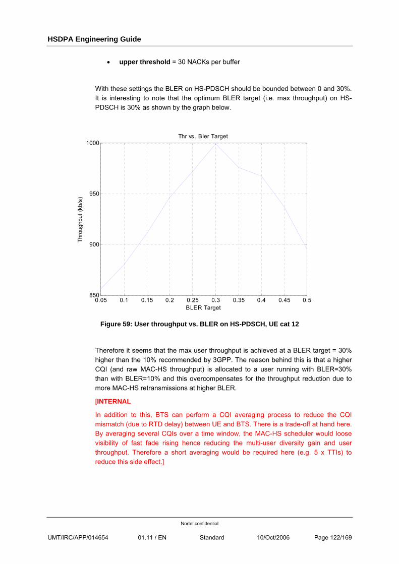
HSDPA Engineering Guide
Nortel confidential
UMT/IRC/APP/014654 01.11 / EN Standard 10/Oct/2006 Page 122/169
• upper threshold = 30 NACKs per buffer
With these settings the BLER on HS-PDSCH should be bounded between 0 and 30%. It is interesting to note that the optimum BLER target (i.e. max throughput) on HS-PDSCH is 30% as shown by the graph below.
0.05 0.1 0.15 0.2 0.25 0.3 0.35 0.4 0.45 0.5850
900
950
1000
BLER Target
Thro
ughp
ut (k
b/s)
Thr vs. Bler Target
Figure 59: User throughput vs. BLER on HS-PDSCH, UE cat 12
Therefore it seems that the max user throughput is achieved at a BLER target = 30% higher than the 10% recommended by 3GPP. The reason behind this is that a higher CQI (and raw MAC-HS throughput) is allocated to a user running with BLER=30% than with BLER=10% and this overcompensates for the throughput reduction due to more MAC-HS retransmissions at higher BLER.
[INTERNAL
In addition to this, BTS can perform a CQI averaging process to reduce the CQI mismatch (due to RTD delay) between UE and BTS. There is a trade-off at hand here. By averaging several CQIs over a time window, the MAC-HS scheduler would loose visibility of fast fade rising hence reducing the multi-user diversity gain and user throughput. Therefore a short averaging would be required here (e.g. 5 x TTIs) to reduce this side effect.]
HSDPA Engineering Guide
Nortel confidential
UMT/IRC/APP/014654 01.11 / EN Standard 10/Oct/2006 Page 123/169
7.4 BTS CREDIT ALLOCATION
Periodically BTS sends capacity/credits allocations to RNC allowing it to transmit data in DL. In case the time period between subsequent capacity allocations is too high, BTS buffer could become empty and throughput degrades. On the other hand if this period is too small then too much Iub signalling is generated impacting RNC and BTS capacity. The parameter controlling this capacity allocation is
• hsdschInterval = 50 ms (recommended value)
To compensate for potential throughput variations during hsdschInterval, BTS uses an overestimating capacity factor which increases the allocated capacity over the estimated value. This would reduce the probability of BTS buffer being empty. This parameter is
• maxRateGrowth = 8 (default value; i.e. 2 times estimated value)
Excessive buffering at BTS is not required to avoid BTS buffer overflow. Also during primary cell change this may lead to packet discard at old BTS. The above parameter values provide good trade-off for BTS capacity/credit allocation.
7.5 HARQ RETRANSMISSIONS
HARQ performs fast retransmissions between UE at BTS for each MAC-HS PDU which is NACked by UE. The max delay between two subsequent retransmissions is 12 ms (i.e. 6 x TTIs). Due to the short delay and soft combing of these HARQ retransmissions they are more efficient than RLC retransmissions (still possible). Therefore enough HARQ retransmissions should be allowed to recover most of the radio errors. Thus the radio errors recovery process is mainly done at HARQ level which increases the throughput. The retransmission process of each MAC-HS PDU is controlled by the following parameters at BTS
• harqNbMaxRetransmissions = 7 (default); max number of allowed HARQ retransmissions (incl. 1st transmission). The 3GPP standard allows up to 15 HARQ retransmissions per MAC-HS PDU.
If harqNbMaxRetransmissions is too small then some radio errors cannot be recovered at HARQ layer leading to RLC retransmissions which takes longer reducing therefore the throughput. On the other hand if harqNbMaxRetransmissions is too large it could stall other transmissions (e.g. for other or the same users) sharing the HSDPA pipe. Very high harqNbMaxRetransmissions would also increase the RLC timers in both UL and DL reducing the recovery speed of radio errors in TCP ACKs sent in UL direction.
Lab experiments show that harqNbMaxRetransmissions = 7 is sufficient to recover from all radio errors. Note that each retransmitted MAC-HS PDU is soft combined by UE at HARQ level providing a more efficient recovery process. However difficult radio
HSDPA Engineering Guide
Nortel confidential
UMT/IRC/APP/014654 01.11 / EN Standard 10/Oct/2006 Page 124/169
environments (i.e. street corner, correlated fading) may require higher number of HARQ retransmissions (up to 15).
• TimerT1 = 100 ms (default value); this is a stall avoidance timer running at BTS; if this timer expires and the corresponding MAC-HS PDU has not been ACKed by UE then BTS stops retransmitting this PDU. This timer is linked to harqNbMaxRetransmissions by the following formula:
TimerT1 ≥ harqNbMaxRetransmissions * 12 ms
• discardTimer = 500 ms (default 3000); if this timer expires and the corresponding MAC-HS PDU has not been ACKed by UE then this PDU will be discarded. The RLC layer will retransmit it so no packet loss occurs. The discardTimer > TimerT1 to allow HARQ recovery before discarding it. Typically RLC layer will retransmit a MAC-d PDU after timer poll prohibit = 300 ms expires. To avoid duplicated PDUs in BTS buffer it is recommended to keep discardTimer >= 500 ms.
• macHsWindowSize = 32 MAC-HS PDUs (default value); This parameter defines the receiver and transmitter MAC-hs PDU window size.
7.6 RLC SETTINGS FOR UL DCH
The round trip delay (RTD) is shorter when HSDPA is used in DL due to shorter DL TTI = 2 ms (compared to 20 ms or 10 ms used for R99 DCH channels). With HSDPA typical RTD = 75 ms while with R99 DCH the RTD > 150 ms. Consequently shorter RLC timers could be used whenever HSDPA is used in DL therefore increasing the speed of radio error recovery (mainly in UL direction as HARQ takes care of DL). Faster UL error recovery means higher DL throughput because TCP ACKs are delivered in time to TCP sender avoiding TCP throughput stalling. In this section the RLC settings for UL DCH are discussed.
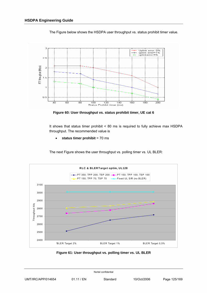
HSDPA Engineering Guide
Nortel confidential
UMT/IRC/APP/014654 01.11 / EN Standard 10/Oct/2006 Page 125/169
The Figure below shows the HSDPA user throughput vs. status prohibit timer value.
Figure 60: User throughput vs. status prohibit timer, UE cat 6
It shows that status timer prohibit < 80 ms is required to fully achieve max HSDPA throughput. The recommended value is
• status timer prohibit = 70 ms
The next Figure shows the user throughput vs. polling timer vs. UL BLER:
RLC & B LER T arge t optim, UL128
2400
2500
2600
2700
2800
2900
3000
3100
'B LE R Target 2% B LE R Target 1% B LE R Target 0,5%
Thr
ough
put
kbp
P T 350; TP P 200; TS P 200 P T 150; TP P 100; TS P 100P T 150; TP P 70; TS P 70 Fixed UL S IR (no B LE R)
Figure 61: User throughput vs. polling timer vs. UL BLER
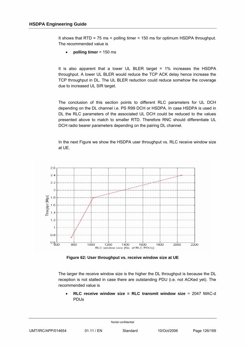
HSDPA Engineering Guide
Nortel confidential
UMT/IRC/APP/014654 01.11 / EN Standard 10/Oct/2006 Page 126/169
It shows that RTD = 75 ms < polling timer < 150 ms for optimum HSDPA throughput. The recommended value is
• polling timer = 150 ms
It is also apparent that a lower UL BLER target = 1% increases the HSDPA throughput. A lower UL BLER would reduce the TCP ACK delay hence increase the TCP throughput in DL. The UL BLER reduction could reduce somehow the coverage due to increased UL SIR target.
The conclusion of this section points to different RLC parameters for UL DCH depending on the DL channel i.e. PS R99 DCH or HSDPA. In case HSDPA is used in DL the RLC parameters of the associated UL DCH could be reduced to the values presented above to match to smaller RTD. Therefore RNC should differentiate UL DCH radio bearer parameters depending on the pairing DL channel.
In the next Figure we show the HSDPA user throughput vs. RLC receive window size at UE.
Figure 62: User throughput vs. receive window size at UE
The larger the receive window size is the higher the DL throughput is because the DL reception is not stalled in case there are outstanding PDU (i.e. not ACKed yet). The recommended value is
• RLC receive window size = RLC transmit window size = 2047 MAC-d PDUs
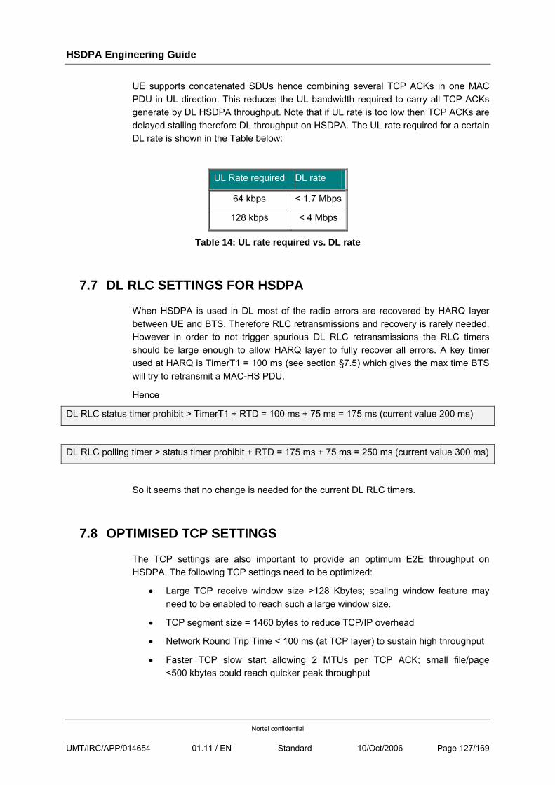
HSDPA Engineering Guide
Nortel confidential
UMT/IRC/APP/014654 01.11 / EN Standard 10/Oct/2006 Page 127/169
UE supports concatenated SDUs hence combining several TCP ACKs in one MAC PDU in UL direction. This reduces the UL bandwidth required to carry all TCP ACKs generate by DL HSDPA throughput. Note that if UL rate is too low then TCP ACKs are delayed stalling therefore DL throughput on HSDPA. The UL rate required for a certain DL rate is shown in the Table below:
UL Rate required DL rate
64 kbps < 1.7 Mbps
128 kbps < 4 Mbps
Table 14: UL rate required vs. DL rate
7.7 DL RLC SETTINGS FOR HSDPA
When HSDPA is used in DL most of the radio errors are recovered by HARQ layer between UE and BTS. Therefore RLC retransmissions and recovery is rarely needed. However in order to not trigger spurious DL RLC retransmissions the RLC timers should be large enough to allow HARQ layer to fully recover all errors. A key timer used at HARQ is TimerT1 = 100 ms (see section §7.5) which gives the max time BTS will try to retransmit a MAC-HS PDU.
Hence
DL RLC status timer prohibit > TimerT1 + RTD = 100 ms + 75 ms = 175 ms (current value 200 ms)
DL RLC polling timer > status timer prohibit + RTD = 175 ms + 75 ms = 250 ms (current value 300 ms)
So it seems that no change is needed for the current DL RLC timers.
7.8 OPTIMISED TCP SETTINGS
The TCP settings are also important to provide an optimum E2E throughput on HSDPA. The following TCP settings need to be optimized:
• Large TCP receive window size >128 Kbytes; scaling window feature may need to be enabled to reach such a large window size.
• TCP segment size = 1460 bytes to reduce TCP/IP overhead
• Network Round Trip Time < 100 ms (at TCP layer) to sustain high throughput
• Faster TCP slow start allowing 2 MTUs per TCP ACK; small file/page <500 kbytes could reach quicker peak throughput
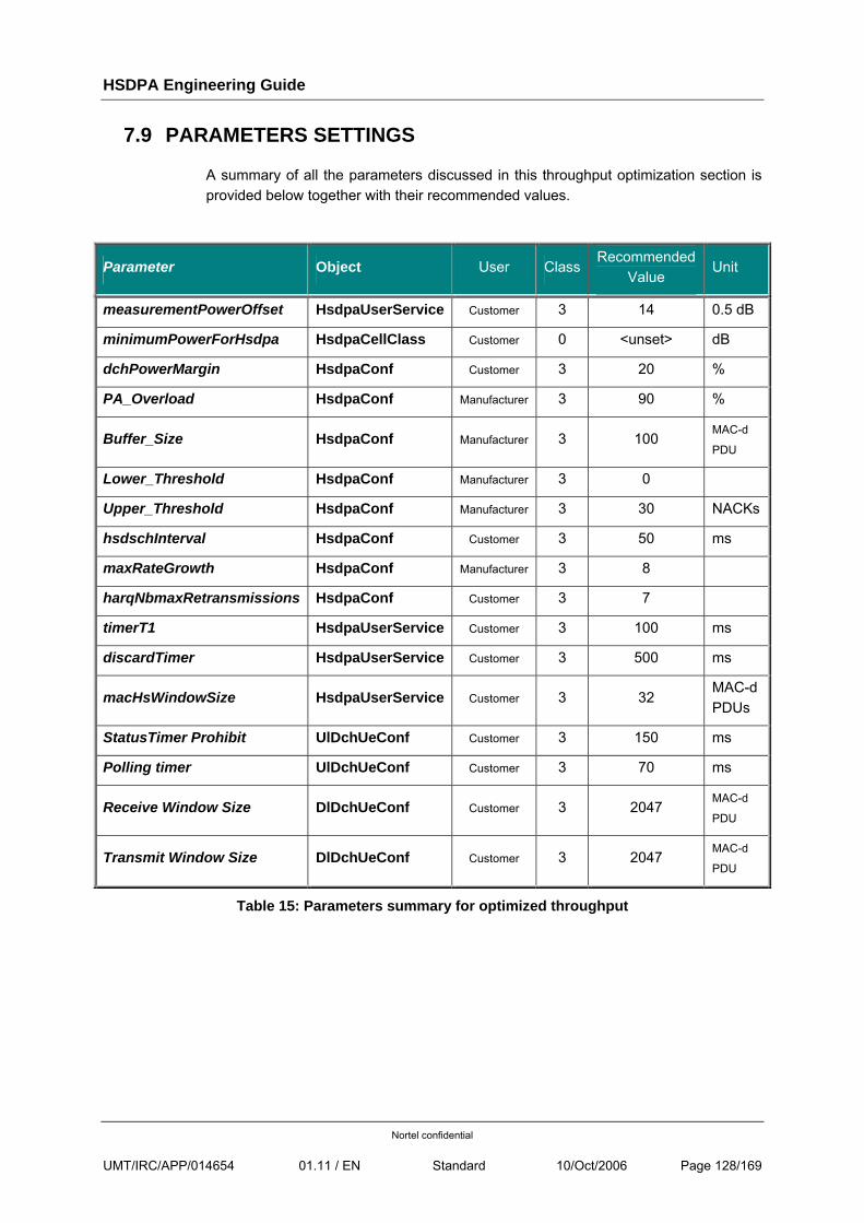
HSDPA Engineering Guide
Nortel confidential
UMT/IRC/APP/014654 01.11 / EN Standard 10/Oct/2006 Page 128/169
7.9 PARAMETERS SETTINGS
A summary of all the parameters discussed in this throughput optimization section is provided below together with their recommended values.
Parameter Object User ClassRecommended
Value Unit
measurementPowerOffset HsdpaUserService Customer 3 14 0.5 dB
minimumPowerForHsdpa HsdpaCellClass Customer 0 <unset> dB
dchPowerMargin HsdpaConf Customer 3 20 %
PA_Overload HsdpaConf Manufacturer 3 90 %
Buffer_Size HsdpaConf Manufacturer 3 100 MAC-d
PDU
Lower_Threshold HsdpaConf Manufacturer 3 0
Upper_Threshold HsdpaConf Manufacturer 3 30 NACKs
hsdschInterval HsdpaConf Customer 3 50 ms
maxRateGrowth HsdpaConf Manufacturer 3 8
harqNbmaxRetransmissions HsdpaConf Customer 3 7
timerT1 HsdpaUserService Customer 3 100 ms
discardTimer HsdpaUserService Customer 3 500 ms
macHsWindowSize HsdpaUserService Customer 3 32 MAC-d PDUs
StatusTimer Prohibit UlDchUeConf Customer 3 150 ms
Polling timer UlDchUeConf Customer 3 70 ms
Receive Window Size DlDchUeConf Customer 3 2047 MAC-d
PDU
Transmit Window Size DlDchUeConf Customer 3 2047 MAC-d
PDU
Table 15: Parameters summary for optimized throughput
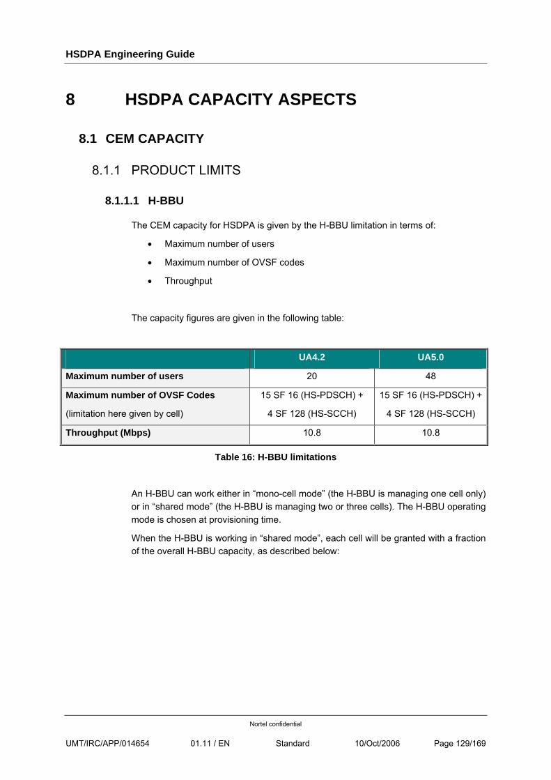
HSDPA Engineering Guide
Nortel confidential
UMT/IRC/APP/014654 01.11 / EN Standard 10/Oct/2006 Page 129/169
8 HSDPA CAPACITY ASPECTS
8.1 CEM CAPACITY
8.1.1 PRODUCT LIMITS
8.1.1.1 H-BBU
The CEM capacity for HSDPA is given by the H-BBU limitation in terms of:
• Maximum number of users
• Maximum number of OVSF codes
• Throughput
The capacity figures are given in the following table:
UA4.2 UA5.0
Maximum number of users 20 48
Maximum number of OVSF Codes
(limitation here given by cell)
15 SF 16 (HS-PDSCH) +
4 SF 128 (HS-SCCH)
15 SF 16 (HS-PDSCH) +
4 SF 128 (HS-SCCH)
Throughput (Mbps) 10.8 10.8
Table 16: H-BBU limitations
An H-BBU can work either in “mono-cell mode” (the H-BBU is managing one cell only) or in “shared mode” (the H-BBU is managing two or three cells). The H-BBU operating mode is chosen at provisioning time.
When the H-BBU is working in “shared mode”, each cell will be granted with a fraction of the overall H-BBU capacity, as described below:
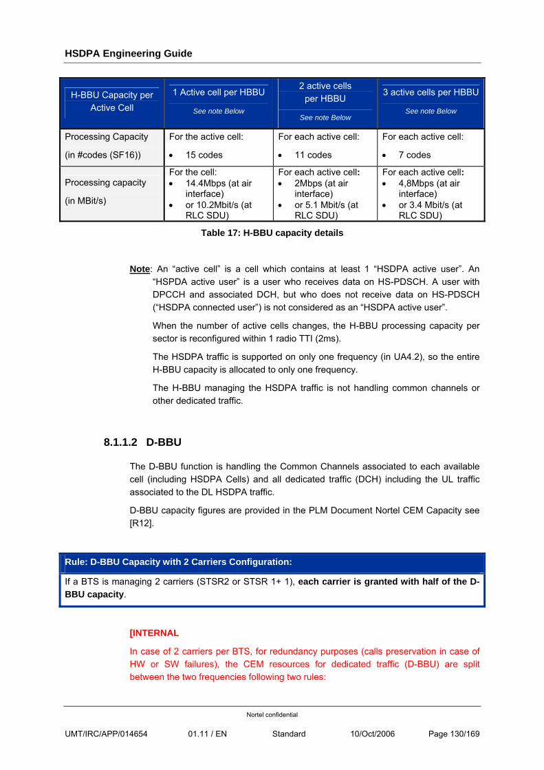
HSDPA Engineering Guide
Nortel confidential
UMT/IRC/APP/014654 01.11 / EN Standard 10/Oct/2006 Page 130/169
H-BBU Capacity per Active Cell
1 Active cell per HBBU
See note Below
2 active cells per HBBU
See note Below
3 active cells per HBBU
See note Below
Processing Capacity
(in #codes (SF16))
For the active cell:
• 15 codes
For each active cell:
• 11 codes
For each active cell:
• 7 codes
Processing capacity
(in MBit/s)
For the cell: • 14.4Mbps (at air
interface) • or 10.2Mbit/s (at
RLC SDU)
For each active cell: • 2Mbps (at air
interface) • or 5.1 Mbit/s (at
RLC SDU)
For each active cell: • 4,8Mbps (at air
interface) • or 3.4 Mbit/s (at
RLC SDU)
Table 17: H-BBU capacity details
Note: An “active cell” is a cell which contains at least 1 “HSDPA active user”. An “HSPDA active user” is a user who receives data on HS-PDSCH. A user with DPCCH and associated DCH, but who does not receive data on HS-PDSCH (“HSDPA connected user”) is not considered as an “HSDPA active user”.
When the number of active cells changes, the H-BBU processing capacity per sector is reconfigured within 1 radio TTI (2ms).
The HSDPA traffic is supported on only one frequency (in UA4.2), so the entire H-BBU capacity is allocated to only one frequency.
The H-BBU managing the HSDPA traffic is not handling common channels or other dedicated traffic.
8.1.1.2 D-BBU
The D-BBU function is handling the Common Channels associated to each available cell (including HSDPA Cells) and all dedicated traffic (DCH) including the UL traffic associated to the DL HSDPA traffic.
D-BBU capacity figures are provided in the PLM Document Nortel CEM Capacity see [R12].
Rule: D-BBU Capacity with 2 Carriers Configuration:
If a BTS is managing 2 carriers (STSR2 or STSR 1+ 1), each carrier is granted with half of the D-BBU capacity.
[INTERNAL
In case of 2 carriers per BTS, for redundancy purposes (calls preservation in case of HW or SW failures), the CEM resources for dedicated traffic (D-BBU) are split between the two frequencies following two rules:
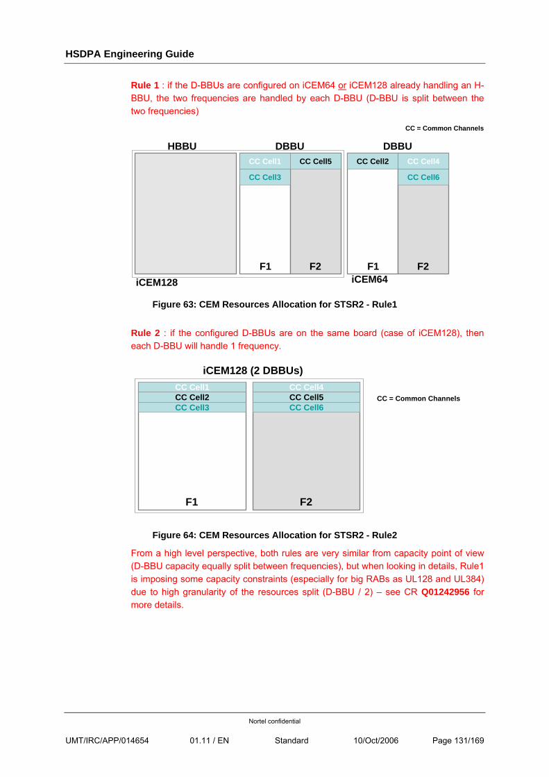
HSDPA Engineering Guide
Nortel confidential
UMT/IRC/APP/014654 01.11 / EN Standard 10/Oct/2006 Page 131/169
Rule 1 : if the D-BBUs are configured on iCEM64 or iCEM128 already handling an H-BBU, the two frequencies are handled by each D-BBU (D-BBU is split between the two frequencies)
Figure 63: CEM Resources Allocation for STSR2 - Rule1
Rule 2 : if the configured D-BBUs are on the same board (case of iCEM128), then each D-BBU will handle 1 frequency.
Figure 64: CEM Resources Allocation for STSR2 - Rule2
From a high level perspective, both rules are very similar from capacity point of view (D-BBU capacity equally split between frequencies), but when looking in details, Rule1 is imposing some capacity constraints (especially for big RABs as UL128 and UL384) due to high granularity of the resources split (D-BBU / 2) – see CR Q01242956 for more details.
iCEM128 (2 DBBUs)
F1 F2
CC Cell1 CC Cell4CC Cell2 CC Cell5CC Cell3 CC Cell6
CC = Common Channels
DBBU
F1 F2
DBBU
F1 F2
CC Cell1 CC Cell4CC Cell2CC Cell5
CC Cell3 CC Cell6
CC = Common Channels
iCEM128
HBBU
iCEM64
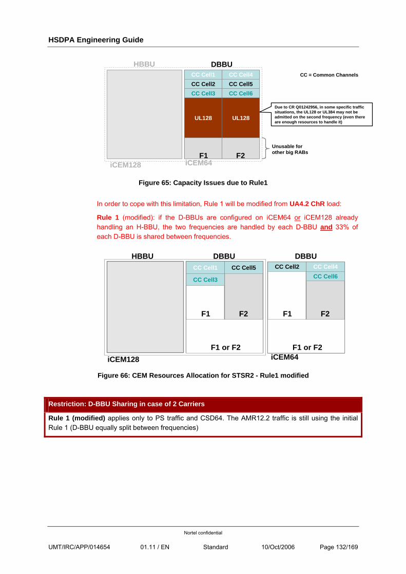
HSDPA Engineering Guide
Nortel confidential
UMT/IRC/APP/014654 01.11 / EN Standard 10/Oct/2006 Page 132/169
Figure 65: Capacity Issues due to Rule1
In order to cope with this limitation, Rule 1 will be modified from UA4.2 ChR load:
Rule 1 (modified): if the D-BBUs are configured on iCEM64 or iCEM128 already handling an H-BBU, the two frequencies are handled by each D-BBU and 33% of each D-BBU is shared between frequencies.
Figure 66: CEM Resources Allocation for STSR2 - Rule1 modified
Restriction: D-BBU Sharing in case of 2 Carriers
Rule 1 (modified) applies only to PS traffic and CSD64. The AMR12.2 traffic is still using the initial Rule 1 (D-BBU equally split between frequencies)
DBBU
F1 F2
CC Cell4CC Cell2CC Cell6
F1 or F2
DBBU
F1 F2
CC Cell1 CC Cell5
CC Cell3
iCEM128
HBBU
iCEM64F1 or F2
DBBUCC Cell1 CC Cell4CC Cell2 CC Cell5CC Cell3 CC Cell6
UL128 UL128
Due to CR Q01242956, in some specific traffic situations, the UL128 or UL384 may not be admitted on the second frequency (even there are enough resources to handle it)
F2F1Unusable for other big RABs
CC = Common Channels
HBBU
iCEM128 iCEM64
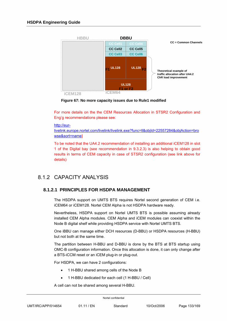
HSDPA Engineering Guide
Nortel confidential
UMT/IRC/APP/014654 01.11 / EN Standard 10/Oct/2006 Page 133/169
Figure 67: No more capacity issues due to Rule1 modified
For more details on the the CEM Resources Allocation in STSR2 Configuration and Eng’g recommendations please see:
http://eur-livelink.europe.nortel.com/livelink/livelink.exe?func=ll&objId=22557284&objAction=browse&sort=name]
To be noted that the UA4.2 recommendation of installing an additional iCEM128 in slot 1 of the Digital bay (see recommendation in 9.3.2.3) is also helping to obtain good results in terms of CEM capacity in case of STSR2 configuration (see link above for details)
8.1.2 CAPACITY ANALYSIS
8.1.2.1 PRINCIPLES FOR HSDPA MANAGEMENT
The HSDPA support on UMTS BTS requires Nortel second generation of CEM i.e. iCEM64 or iCEM128. Nortel CEM Alpha is not HSDPA hardware ready.
Nevertheless, HSDPA support on Nortel UMTS BTS is possible assuming already installed CEM Alpha modules. CEM Alpha and iCEM modules can coexist within the Node B digital shelf while providing HSDPA service with Nortel UMTS BTS.
One iBBU can manage either DCH resources (D-BBU) or HSDPA resources (H-BBU) but not both at the same time.
The partition between H-BBU and D-BBU is done by the BTS at BTS startup using OMC-B configuration information. Once this allocation is done, it can only change after a BTS-iCCM reset or an iCEM plug-in or plug-out.
For HSDPA, we can have 2 configurations:
• 1 H-BBU shared among cells of the Node B
• 1 H-BBU dedicated for each cell (1 H-BBU / Cell)
A cell can not be shared among several H-BBU.
CC Cell2
DBBUCC Cell1
CC Cell5CC Cell3
CC Cell4
CC Cell6
UL128F1 UL128 F2
UL128F1 or F2
CC = Common Channels
Theoretical example of traffic allocation after UA4.2 ChR load improvement
HBBU
iCEM128 iCEM64
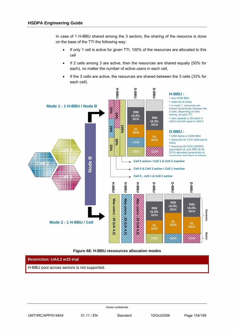
HSDPA Engineering Guide
Nortel confidential
UMT/IRC/APP/014654 01.11 / EN Standard 10/Oct/2006 Page 134/169
In case of 1 H-BBU shared among the 3 sectors, the sharing of the resource is done on the base of the TTI the following way:
• If only 1 cell is active for given TTI, 100% of the resources are allocated to this cell
• If 2 cells among 3 are active, then the resources are shared equally (50% for each), no matter the number of active users in each cell,
• If the 3 cells are active, the resources are shared between the 3 cells (33% for each cell).
Cell 0
Cell 2
Cell 1
H-B
BU
D-B
BU
H-B
BU
H-B
BU
D-B
BU
D-B
BU
Mode 2 : 1 H-BBU / Cell
H-B
BU
D-B
BU
D-B
BU
Mode 1 : 1 H-BBU / Node B 33%
33%
33%
50%
50%
100%
Cell 0 & Cell 2 active / Cell 1 inactive
Cell 0 , cell 1 & Cell 2 active
Cell 0 active / Cell 1 & Cell 2 inactive
CCH
CCH CCH
CCH CCH CCH
UL DCH
UL DCH
UL DCH
UL DCH UL
DCH
R99 UL/DL DCH R99
UL/DL DCH
R99 UL/DL DCH
R99 UL/DL DCH
R99 UL/DL DCH
H-BBU : • only iCEM BBU • reserved at setup • in mode 1, resources are shared dynamically between the 3 cells, depending on their activity, at each TTI • max capacity is 20 users in UA4.2 and 64 users in UA5.0
D-BBU : • CEM Alpha or iCEM BBU • resources for CCH reserved at setup • resources for DCH (HSDPA associated UL and R99 UL/DL DCH) allocated dynamically at connection and freed at release.
Max users : 20 (U
A 4.2)
Max users : 20 (U
A 4.2)
Max users : 20 (U
A 4.2)
Nod
e B
Dynam
ic Static
Figure 68: H-BBU ressources allocation modes
Restriction: UA4.2 w33 trial
H-BBU pool across sectors is not supported.
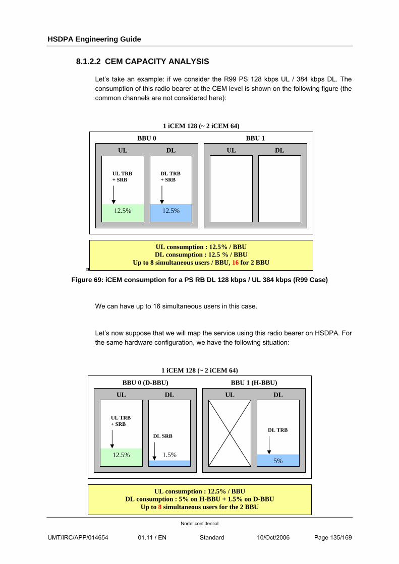
HSDPA Engineering Guide
Nortel confidential
UMT/IRC/APP/014654 01.11 / EN Standard 10/Oct/2006 Page 135/169
8.1.2.2 CEM CAPACITY ANALYSIS
Let’s take an example: if we consider the R99 PS 128 kbps UL / 384 kbps DL. The consumption of this radio bearer at the CEM level is shown on the following figure (the common channels are not considered here):
n
Figure 69: iCEM consumption for a PS RB DL 128 kbps / UL 384 kbps (R99 Case)
We can have up to 16 simultaneous users in this case.
Let’s now suppose that we will map the service using this radio bearer on HSDPA. For the same hardware configuration, we have the following situation:
BBU 0
UL DL
12.5% 12.5%
1 iCEM 128 (~ 2 iCEM 64)
UL DL
BBU 1
UL consumption : 12.5% / BBU DL consumption : 12.5 % / BBU
Up to 8 simultaneous users / BBU, 16 for 2 BBU
UL TRB + SRB
DL TRB + SRB
BBU 0 (D-BBU)
UL DL
12.5%
1 iCEM 128 (~ 2 iCEM 64)
UL DL
BBU 1 (H-BBU)
UL consumption : 12.5% / BBU DL consumption : 5% on H-BBU + 1.5% on D-BBU
Up to 8 simultaneous users for the 2 BBU
5%
DL SRB
1.5%
UL TRB + SRB
DL TRB
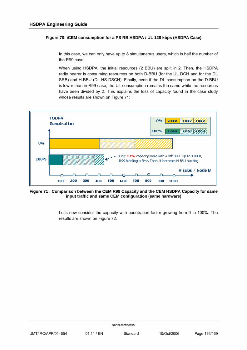
HSDPA Engineering Guide
Nortel confidential
UMT/IRC/APP/014654 01.11 / EN Standard 10/Oct/2006 Page 136/169
Figure 70: iCEM consumption for a PS RB HSDPA / UL 128 kbps (HSDPA Case)
In this case, we can only have up to 8 simultaneous users, which is half the number of the R99 case.
When using HSDPA, the initial resources (2 BBU) are split in 2. Then, the HSDPA radio bearer is consuming resources on both D-BBU (for the UL DCH and for the DL SRB) and H-BBU (DL HS-DSCH). Finally, even if the DL consumption on the D-BBU is lower than in R99 case, the UL consumption remains the same while the resources have been divided by 2. This explains the loss of capacity found in the case study whose results are shown on Figure 71:
Figure 71 : Comparison between the CEM R99 Capacity and the CEM HSDPA Capacity for same
input traffic and same CEM configuration (same hardware)
Let’s now consider the capacity with penetration factor growing from 0 to 100%. The results are shown on Figure 72:
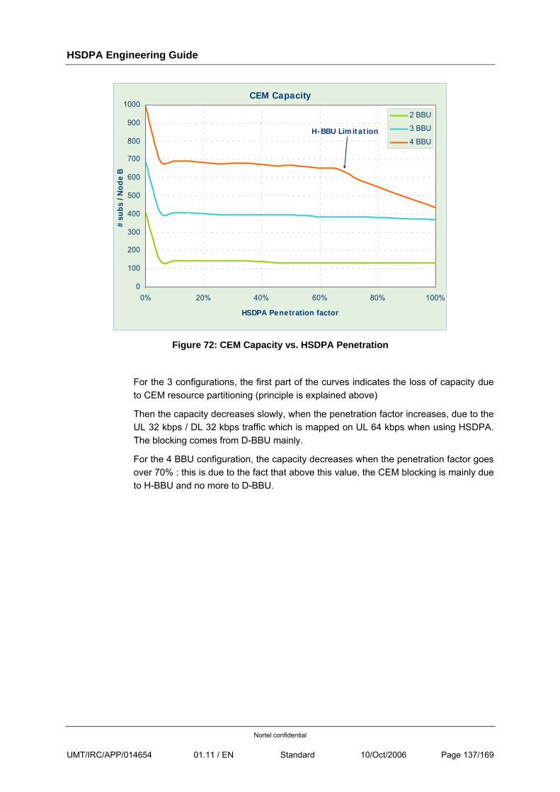
HSDPA Engineering Guide
Nortel confidential
UMT/IRC/APP/014654 01.11 / EN Standard 10/Oct/2006 Page 137/169
CEM Capacity
0
100
200
300
400
500
600
700
800
900
1000
0% 20% 40% 60% 80% 100%
HSDPA Penetration factor
# su
bs /
Nod
e B
2 BBU
3 BBU
4 BBUH-BBU Limitation
Figure 72: CEM Capacity vs. HSDPA Penetration
For the 3 configurations, the first part of the curves indicates the loss of capacity due to CEM resource partitioning (principle is explained above)
Then the capacity decreases slowly, when the penetration factor increases, due to the UL 32 kbps / DL 32 kbps traffic which is mapped on UL 64 kbps when using HSDPA. The blocking comes from D-BBU mainly.
For the 4 BBU configuration, the capacity decreases when the penetration factor goes over 70% : this is due to the fact that above this value, the CEM blocking is mainly due to H-BBU and no more to D-BBU.
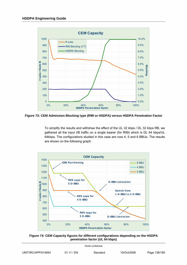
HSDPA Engineering Guide
Nortel confidential
UMT/IRC/APP/014654 01.11 / EN Standard 10/Oct/2006 Page 138/169
CEM Capacity
0
100
200
300
400
500
600
700
800
900
1000
0% 20% 40% 60% 80% 100%HSDPA Penetration factor
# su
bs /
Nod
e B
0.0%
1.0%
2.0%
3.0%
4.0%
5.0%
6.0%
7.0%
8.0%
9.0%
10.0%B
locking# subs
R99 Blocking (VT)
HSDPA Blocking
Figure 73: CEM Admission Blocking type (R99 or HSDPA) versus HSDPA Penetration Factor
To simplify the results and withdraw the effect of the UL 32 kbps / DL 32 kbps RB, we gathered all the input I/B traffic on a single bearer (for R99) which is DL 64 kbps/UL 64kbps. The configurations studied in this case are now 4, 5 and 6 BBUs. The results are shown on the following graph:
CEM Capacity
400
500
600
700
800
900
1000
1100
1200
1300
1400
0% 20% 40% 60% 80% 100%HSDPA Penetration factor
# su
bs /
Nod
e B
6 BBU
4 BBU
5 BBU
R99 capa for 3 D-BBU
R99 capa for 4 D-BBU
R99 capa for 5 D-BBU
Switch from 1 H-BBU to 3 H-BBU
H-BBU Limitation
CEM Partitioning
D-BBU Limitation
Figure 74: CEM Capacity figures for different configurations depending on the HSDPA
penetration factor (UL 64 kbps)
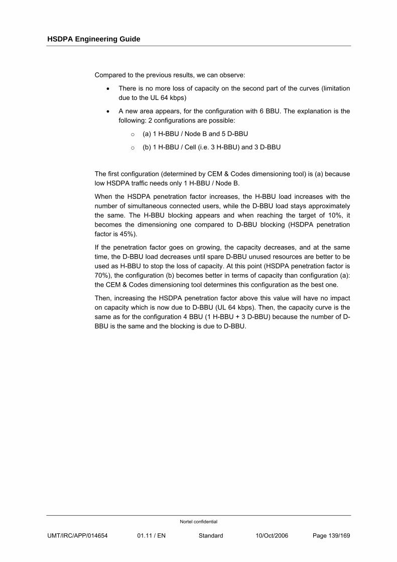
HSDPA Engineering Guide
Nortel confidential
UMT/IRC/APP/014654 01.11 / EN Standard 10/Oct/2006 Page 139/169
Compared to the previous results, we can observe:
• There is no more loss of capacity on the second part of the curves (limitation due to the UL 64 kbps)
• A new area appears, for the configuration with 6 BBU. The explanation is the following: 2 configurations are possible:
o (a) 1 H-BBU / Node B and 5 D-BBU
o (b) 1 H-BBU / Cell (i.e. 3 H-BBU) and 3 D-BBU
The first configuration (determined by CEM & Codes dimensioning tool) is (a) because low HSDPA traffic needs only 1 H-BBU / Node B.
When the HSDPA penetration factor increases, the H-BBU load increases with the number of simultaneous connected users, while the D-BBU load stays approximately the same. The H-BBU blocking appears and when reaching the target of 10%, it becomes the dimensioning one compared to D-BBU blocking (HSDPA penetration factor is 45%).
If the penetration factor goes on growing, the capacity decreases, and at the same time, the D-BBU load decreases until spare D-BBU unused resources are better to be used as H-BBU to stop the loss of capacity. At this point (HSDPA penetration factor is 70%), the configuration (b) becomes better in terms of capacity than configuration (a): the CEM & Codes dimensioning tool determines this configuration as the best one.
Then, increasing the HSDPA penetration factor above this value will have no impact on capacity which is now due to D-BBU (UL 64 kbps). Then, the capacity curve is the same as for the configuration 4 BBU (1 H-BBU + 3 D-BBU) because the number of D-BBU is the same and the blocking is due to D-BBU.
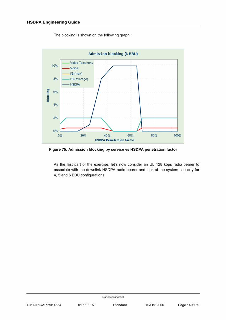
HSDPA Engineering Guide
Nortel confidential
UMT/IRC/APP/014654 01.11 / EN Standard 10/Oct/2006 Page 140/169
The blocking is shown on the following graph :
Admission blocking (6 BBU)
0%
2%
4%
6%
8%
10%
0% 20% 40% 60% 80% 100%HSDPA Penetration factor
Blo
ckin
g
Video Telephony
Voice
I/B (max)
I/B (average)
HSDPA
Figure 75: Admission blocking by service vs HSDPA penetration factor
As the last part of the exercise, let’s now consider an UL 128 kbps radio bearer to associate with the downlink HSDPA radio bearer and look at the system capacity for 4, 5 and 6 BBU configurations:
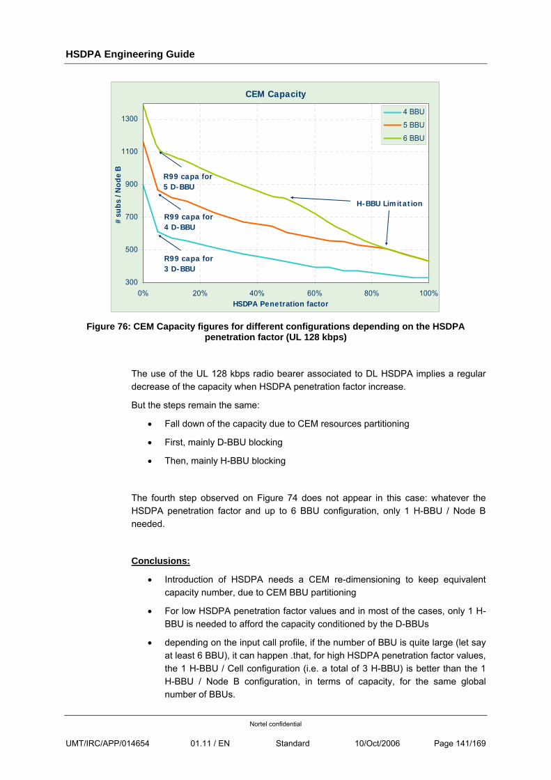
HSDPA Engineering Guide
Nortel confidential
UMT/IRC/APP/014654 01.11 / EN Standard 10/Oct/2006 Page 141/169
CEM Capacity
300
500
700
900
1100
1300
0% 20% 40% 60% 80% 100%HSDPA Penetration factor
# su
bs /
Nod
e B
4 BBU
5 BBU
6 BBU
R99 capa for 3 D-BBU
R99 capa for 4 D-BBU
R99 capa for 5 D-BBU
H-BBU Limitation
Figure 76: CEM Capacity figures for different configurations depending on the HSDPA
penetration factor (UL 128 kbps)
The use of the UL 128 kbps radio bearer associated to DL HSDPA implies a regular decrease of the capacity when HSDPA penetration factor increase.
But the steps remain the same:
• Fall down of the capacity due to CEM resources partitioning
• First, mainly D-BBU blocking
• Then, mainly H-BBU blocking
The fourth step observed on Figure 74 does not appear in this case: whatever the HSDPA penetration factor and up to 6 BBU configuration, only 1 H-BBU / Node B needed.
Conclusions:
• Introduction of HSDPA needs a CEM re-dimensioning to keep equivalent capacity number, due to CEM BBU partitioning
• For low HSDPA penetration factor values and in most of the cases, only 1 H-BBU is needed to afford the capacity conditioned by the D-BBUs
• depending on the input call profile, if the number of BBU is quite large (let say at least 6 BBU), it can happen .that, for high HSDPA penetration factor values, the 1 H-BBU / Cell configuration (i.e. a total of 3 H-BBU) is better than the 1 H-BBU / Node B configuration, in terms of capacity, for the same global number of BBUs.
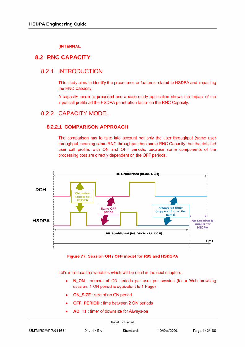
HSDPA Engineering Guide
Nortel confidential
UMT/IRC/APP/014654 01.11 / EN Standard 10/Oct/2006 Page 142/169
[INTERNAL
8.2 RNC CAPACITY
8.2.1 INTRODUCTION
This study aims to identify the procedures or features related to HSDPA and impacting the RNC Capacity.
A capacity model is proposed and a case study application shows the impact of the input call profile ad the HSDPA penetration factor on the RNC Capacity.
8.2.2 CAPACITY MODEL
8.2.2.1 COMPARISON APPROACH
The comparison has to take into account not only the user throughput (same user throughput meaning same RNC throughput then same RNC Capacity) but the detailed user call profile, with ON and OFF periods, because some components of the processing cost are directly dependent on the OFF periods.
Figure 77: Session ON / OFF model for R99 and HSDSPA
Let’s introduce the variables which will be used in the next chapters :
• N_ON : number of ON periods per user per session (for a Web browsing session, 1 ON period is equivalent to 1 Page)
• ON_SIZE : size of an ON period
• OFF_PERIOD : time between 2 ON periods
• AO_T1 : timer of downsize for Always-on
RB Established (UL/DL DCH)
RB Established (HS-DSCH + UL DCH)
Time
RB Duration issmaller for
HSDPA
Same OFF period
ON periodshorter for
HSDPA
Always-on timer(supposed to be the
same)
RB Established (UL/DL DCH)
RB Established (HS-DSCH + UL DCH)
Time
RB Duration issmaller for
HSDPA
Same OFF period
ON periodshorter for
HSDPA
Always-on timer(supposed to be the
same)
DCH
HSDPA
HSDPA Engineering Guide
Nortel confidential
UMT/IRC/APP/014654 01.11 / EN Standard 10/Oct/2006 Page 143/169
• T_DCH : time among the session during which a DCH is established
• T_HSDPA : time among the session during which RB is mapped on HS-DSCH (same as time during which a UL DCH is established)
• REQ_SIZE : size of a request message
• DL_SIZE : session DL size (DL_SIZE = N_ON * ON_SIZE)
• UL_SIZE : session UL size (UL_SIZE = N_ON * REQ_SIZE)
• N_RL_PER_UE : mean number of radio link per UE
• RLC_BLER_DL_R99 : BLER DL at RLC level for PS services (R99)
• RLC_BLER_DL_HSDPA : BLER DL at RLC level for PS services (HSDPA)
• F_ASU : Active Set Update frequency
8.2.2.2 QUALITATIVE IMPACT
To quantify the impact of HSDPA on the capacity of the RNC, we have first to list :
• The new procedures and features used for HSDPA and not in R99
• The procedures and features which were used in R99 and are no more with HSDPA
• The procedures and features used for both R99 and HSDPA but which may have different costs at RNC level, due to different statistical models.
The cost of the listed procedures can be dependent on :
• The amount of data transmitted
• The RB connection duration
• Both of the 2 previous factors (indirectly)
The list of new features or procedures related to HSDPA and which have an impact on the RNC capacity are the following :
• HS-DSCH Flow Control :
o Description: This mechanism is used to avoid Node B buffers overflow by controlling the DL traffic of each user multiplexed on HSDSCH common transport channel. It grants a capacity credit for a given period of time to each user.
o Type: mainly periodic message (Capacity Allocation) sent by Node B to RNC (1 message per user per period of time)
o Dependency: RB connection duration
o Impact: User Plane – Reduces capacity
HSDPA Engineering Guide
Nortel confidential
UMT/IRC/APP/014654 01.11 / EN Standard 10/Oct/2006 Page 144/169
• HSDPA Mobility :
o Description: HSDPA uses the primary cell in the active set as the unique link for data transmission in DL. At primary cell update, 2 SRLR procedures are done to reconfigure both the old and the new link.
o Type: 2 additional SRLR procedures at each primary cell update
o Dependency: RB connection duration
o Impact: Control Plane – Reduces capacity
• Macro-diversity :
o Description: HSDPA uses only 1 RL (the primary cell) to transmit in DL., even if the UE is in SHO. No data packet duplication at RNC level for macro-diversity.
o Type: suppress duplication of PDU at RNC for SHO (DL)
o Dependency: data volume
o Impact: User Plane – Increases capacity
The list of R99 features or procedures which are no more used for HSDPA and which have a cost at RNC level is :
• RB Rate Adaptation :
o Description: this feature is used from V4.2 and for R99 PS traffic only to adapt dynamically the bitrate of the radio bearer to the user effective throughput.
o Type: 1 SRLR procedure at RB Rate Adaptation event
o Dependency: both
o Impact: Control Plane – Reduces capacity
• IRM Preemption :
o Description: this feature allows to downgrade some users to free resources to accept new users.
o Type: 1 SRLR procedure per user downgraded at each IRM Preemption event
o Dependency: both
o Impact: Control Plane – Reduces capacity
HSDPA Engineering Guide
Nortel confidential
UMT/IRC/APP/014654 01.11 / EN Standard 10/Oct/2006 Page 145/169
• IRM Scheduling
o Description: this feature allows to downgrade or upgrade users depending on their radio conditions.
o Type: 1 SRLR procedure per user downgrade/upgrade
o Dependency: both
o Impact: Control Plane – Reduces capacity
The list of procedures and features used for both R99 and HSDPA but which may have different costs at RNC level, due to different statistical models, is :
• Iub Bandwidth limitation :
o Description: This mechanism is used to avoid losing DCHFPs on Iub due to traffic peaks. Real time traffic measurements are done on Iub for what is called backpressure mechanism. When a threshold is reached, PMC PC asks PMC RB to stop transmission. It is not specific to HSDPA but the impact could be could be greater than for R99 due to higher peaks.
o Type: triggered message (frequency to evaluate)
o Dependency: data volume
o Impact: User Plane – Reduces capacity
• DL BLER :
o Description: for PS R99 radio bearers, we generally assume a DL BLER of 10%. In case of HSDPA, the new MAC-HS layer and other HSDPA related features should allow to reduce BLER near 0%..
o Type:
o Dependency: data volume
o Impact: User Plane – Reduces capacity
8.2.2.3 USER PLANE MODEL
Here is the list of the components for the User Plane cost estimation.
• HS-DSCH Flow Control (HSDPA):
o Model: Periodic message (typical period is 100ms, 1 message per period). The cost of a message is C_HS_DSCH_FC.
o Dependency: T_HSDPA, flow control period (T_HS_DSCH_FC)
• Processing of traffic data (HSDPA & R99):
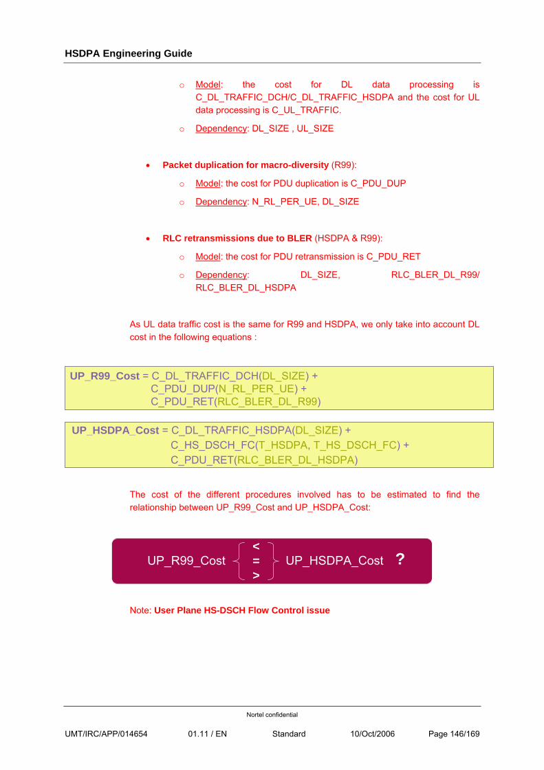
HSDPA Engineering Guide
Nortel confidential
UMT/IRC/APP/014654 01.11 / EN Standard 10/Oct/2006 Page 146/169
o Model: the cost for DL data processing is C_DL_TRAFFIC_DCH/C_DL_TRAFFIC_HSDPA and the cost for UL data processing is C_UL_TRAFFIC.
o Dependency: DL_SIZE , UL_SIZE
• Packet duplication for macro-diversity (R99):
o Model: the cost for PDU duplication is C_PDU_DUP
o Dependency: N_RL_PER_UE, DL_SIZE
• RLC retransmissions due to BLER (HSDPA & R99):
o Model: the cost for PDU retransmission is C_PDU_RET
o Dependency: DL_SIZE, RLC_BLER_DL_R99/ RLC_BLER_DL_HSDPA
As UL data traffic cost is the same for R99 and HSDPA, we only take into account DL cost in the following equations :
UP_R99_Cost = C_DL_TRAFFIC_DCH(DL_SIZE) + C_PDU_DUP(N_RL_PER_UE) +C_PDU_RET(RLC_BLER_DL_R99)
UP_HSDPA_Cost = C_DL_TRAFFIC_HSDPA(DL_SIZE) +
C_HS_DSCH_FC(T_HSDPA, T_HS_DSCH_FC) + C_PDU_RET(RLC_BLER_DL_HSDPA)
The cost of the different procedures involved has to be estimated to find the relationship between UP_R99_Cost and UP_HSDPA_Cost:
UP_R99_Cost UP_HSDPA_Cost<=>
?
Note: User Plane HS-DSCH Flow Control issue
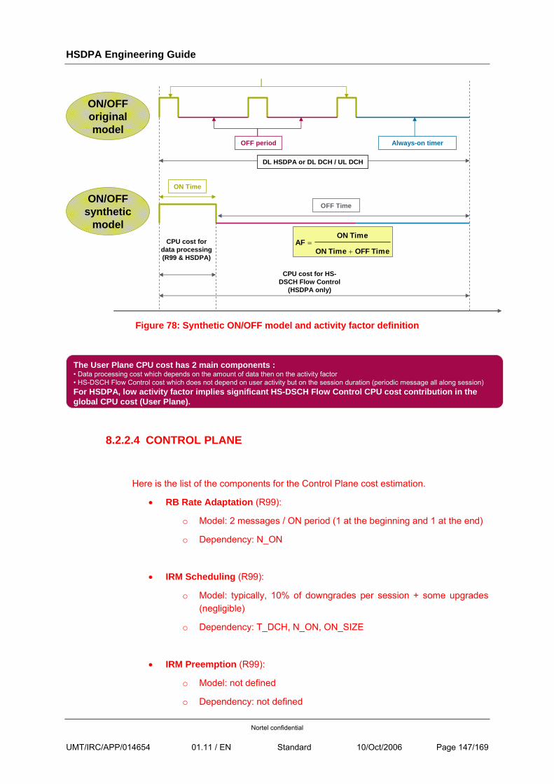
HSDPA Engineering Guide
Nortel confidential
UMT/IRC/APP/014654 01.11 / EN Standard 10/Oct/2006 Page 147/169
DL HSDPA or DL DCH / UL DCH
OFF period Always-on timer
ON/OFForiginal model
ON/OFFsynthetic
model
ON Time
OFF Time
CPU cost for data processing(R99 & HSDPA)
CPU cost for HS-DSCH Flow Control
(HSDPA only)
TimeOFF TimeON
TimeONAF
+=
Figure 78: Synthetic ON/OFF model and activity factor definition
The User Plane CPU cost has 2 main components :• Data processing cost which depends on the amount of data then on the activity factor• HS-DSCH Flow Control cost which does not depend on user activity but on the session duration (periodic message all along session)For HSDPA, low activity factor implies significant HS-DSCH Flow Control CPU cost contribution in the global CPU cost (User Plane).
8.2.2.4 CONTROL PLANE
Here is the list of the components for the Control Plane cost estimation.
• RB Rate Adaptation (R99):
o Model: 2 messages / ON period (1 at the beginning and 1 at the end)
o Dependency: N_ON
• IRM Scheduling (R99):
o Model: typically, 10% of downgrades per session + some upgrades (negligible)
o Dependency: T_DCH, N_ON, ON_SIZE
• IRM Preemption (R99):
o Model: not defined
o Dependency: not defined
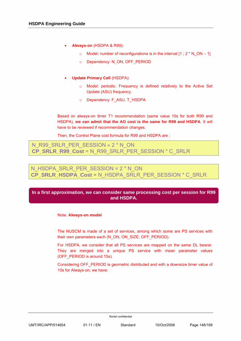
HSDPA Engineering Guide
Nortel confidential
UMT/IRC/APP/014654 01.11 / EN Standard 10/Oct/2006 Page 148/169
• Always-on (HSDPA & R99):
o Model: number of reconfigurations is in the interval [1 ; 2 * N_ON – 1]
o Dependency: N_ON, OFF_PERIOD
• Update Primary Cell (HSDPA):
o Model: periodic. Frequency is defined relatively to the Active Set Update (ASU) frequency.
o Dependency: F_ASU, T_HSDPA
Based on always-on timer T1 recommendation (same value 10s for both R99 and HSDPA), we can admit that the AO cost is the same for R99 and HSDPA. It will have to be reviewed if recommendation changes.
Then, the Control Plane cost formula for R99 and HSDPA are :
N_R99_SRLR_PER_SESSION ≈ 2 * N_ONCP_SRLR_R99_Cost = N_R99_SRLR_PER_SESSION * C_SRLR
N_HSDPA_SRLR_PER_SESSION = 2 * N_ONCP_SRLR_HSDPA_Cost = N_HSDPA_SRLR_PER_SESSION * C_SRLR
In a first approximation, we can consider same processing cost per session for R99 and HSDPA.
Note: Always-on model
The NUSCM is made of a set of services, among which some are PS services with their own parameters each (N_ON, ON_SIZE, OFF_PERIOD).
For HSDPA, we consider that all PS services are mapped on the same DL bearer. They are merged into a unique PS service with mean parameter values (OFF_PERIOD is around 15s).
Considering OFF_PERIOD is geometric distributed and with a downsize timer value of 10s for Always-on, we have:
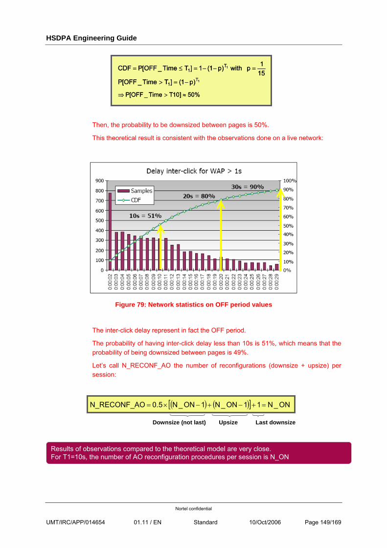
HSDPA Engineering Guide
Nortel confidential
UMT/IRC/APP/014654 01.11 / EN Standard 10/Oct/2006 Page 149/169
151p with )p1(1]TTime_OFF[PCDF 1T
1 =−−=≤=
1T1 )p1(]TTime_OFF[P −=>
%50]10TTime_OFF[P ≈>⇒
151p with )p1(1]TTime_OFF[PCDF 1T
1 =−−=≤=
1T1 )p1(]TTime_OFF[P −=>
%50]10TTime_OFF[P ≈>⇒
Then, the probability to be downsized between pages is 50%.
This theoretical result is consistent with the observations done on a live network:
Figure 79: Network statistics on OFF period values
The inter-click delay represent in fact the OFF period.
The probability of having inter-click delay less than 10s is 51%, which means that the probability of being downsized between pages is 49%.
Let’s call N_RECONF_AO the number of reconfigurations (downsize + upsize) per session:
( ) ( )[ ] ON_N11ON_N1ON_N0.5 ON_RECONF_A =+−+−×=
Downsize (not last) Upsize Last downsize
Results of observations compared to the theoretical model are very close.For T1=10s, the number of AO reconfiguration procedures per session is N_ON
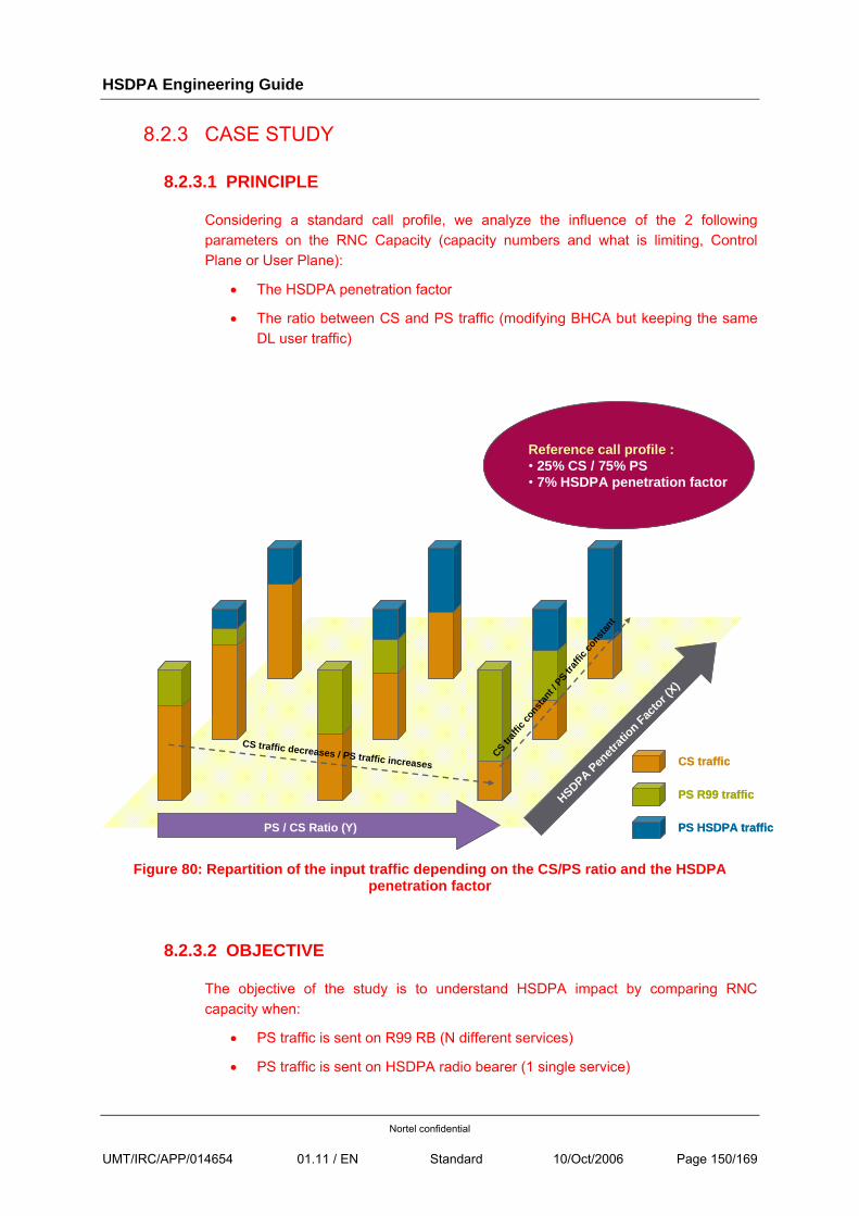
HSDPA Engineering Guide
Nortel confidential
UMT/IRC/APP/014654 01.11 / EN Standard 10/Oct/2006 Page 150/169
8.2.3 CASE STUDY
8.2.3.1 PRINCIPLE
Considering a standard call profile, we analyze the influence of the 2 following parameters on the RNC Capacity (capacity numbers and what is limiting, Control Plane or User Plane):
• The HSDPA penetration factor
• The ratio between CS and PS traffic (modifying BHCA but keeping the same DL user traffic)
PS / CS Ratio (Y)
HSDPA Penetr
ation Fac
tor (X)
CS traffic
PS R99 traffic
PS HSDPA traffic
Reference call profile :• 25% CS / 75% PS• 7% HSDPA penetration factor
CS traffic decreases / PS traffic increases
CS traff
icco
nstan
t / PS tr
affic
cons
tant
PS / CS Ratio (Y)
HSDPA Penetr
ation Fac
tor (X)
CS traffic
PS R99 traffic
PS HSDPA traffic
Reference call profile :• 25% CS / 75% PS• 7% HSDPA penetration factor
CS traffic decreases / PS traffic increases
CS traff
icco
nstan
t / PS tr
affic
cons
tant
Figure 80: Repartition of the input traffic depending on the CS/PS ratio and the HSDPA
penetration factor
8.2.3.2 OBJECTIVE
The objective of the study is to understand HSDPA impact by comparing RNC capacity when:
• PS traffic is sent on R99 RB (N different services)
• PS traffic is sent on HSDPA radio bearer (1 single service)
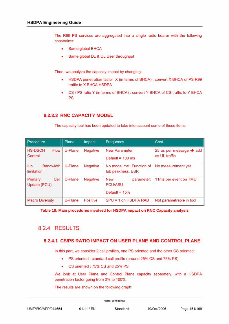
HSDPA Engineering Guide
Nortel confidential
UMT/IRC/APP/014654 01.11 / EN Standard 10/Oct/2006 Page 151/169
The R99 PS services are aggregated into a single radio bearer with the following constraints:
• Same global BHCA
• Same global DL & UL User throughput
Then, we analyze the capacity impact by changing:
• HSDPA penetration factor X (in terms of BHCA) : convert X BHCA of PS R99 traffic to X BHCA HSDPA
• CS / PS ratio Y (in terms of BHCA) : convert Y BHCA of CS traffic to Y BHCA PS
8.2.3.3 RNC CAPACITY MODEL
The capacity tool has been updated to take into account some of these items:
Procedure Plane Impact Frequency Cost
HS-DSCH Flow Control
U-Plane Negative New Parameter
Default = 100 ms
25 us per message add as UL traffic
Iub Bandwidth limitation
U-Plane Negative No model Yet. Function of Iub peakness, EBR
No measurement yet
Primary Cell Update (PCU)
C-Plane Negative New parameter: PCU/ASU
Default = 15%
11ms per event on TMU
Macro Diversity U-Plane Positive SPU = 1 on HSDPA RAB Not parametrable in tool
Table 18: Main procedures involved for HSDPA impact on RNC Capacity analysis
8.2.4 RESULTS
8.2.4.1 CS/PS RATIO IMPACT ON USER PLANE AND CONTROL PLANE
In this part, we consider 2 call profiles, one PS oriented and the other CS oriented:
• PS oriented : standard call profile (around 25% CS and 75% PS)
• CS oriented : 75% CS and 25% PS
We look at User Plane and Control Plane capacity separately, with a HSDPA penetration factor going from 0% to 100%.
The results are shown on the following graph:
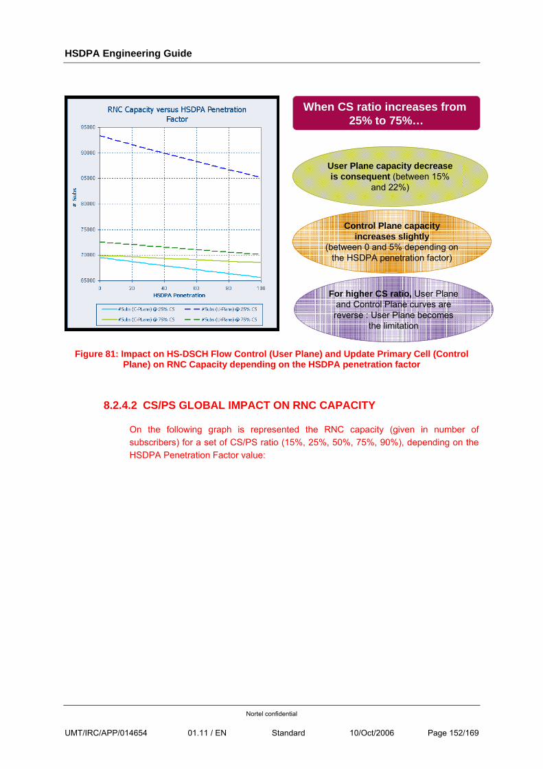
HSDPA Engineering Guide
Nortel confidential
UMT/IRC/APP/014654 01.11 / EN Standard 10/Oct/2006 Page 152/169
User Plane capacity decreaseis consequent (between 15%
and 22%)
Control Plane capacityincreases slightly
(between 0 and 5% depending on the HSDPA penetration factor)
When CS ratio increases from25% to 75%…
For higher CS ratio, User Plane and Control Plane curves are reverse : User Plane becomes
the limitation
Figure 81: Impact on HS-DSCH Flow Control (User Plane) and Update Primary Cell (Control Plane) on RNC Capacity depending on the HSDPA penetration factor
8.2.4.2 CS/PS GLOBAL IMPACT ON RNC CAPACITY
On the following graph is represented the RNC capacity (given in number of subscribers) for a set of CS/PS ratio (15%, 25%, 50%, 75%, 90%), depending on the HSDPA Penetration Factor value:
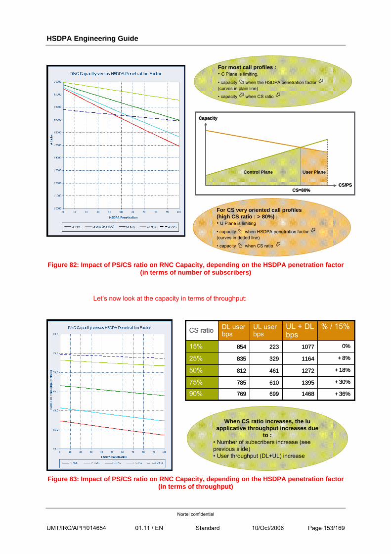
HSDPA Engineering Guide
Nortel confidential
UMT/IRC/APP/014654 01.11 / EN Standard 10/Oct/2006 Page 153/169
For most call profiles :• C Plane is limiting,
• capacity when the HSDPA penetration factor(curves in plain line)
• capacity when CS ratio
For CS very oriented call profiles (high CS ratio : > 80%) :• U Plane is limiting
• capacity when HSDPA penetration factor(curves in dotted line)
• capacity when CS ratio
CS/PS
Capacity
CS=80%
Control Plane User Plane
CS/PS
Capacity
CS=80%
Control Plane User Plane
Figure 82: Impact of PS/CS ratio on RNC Capacity, depending on the HSDPA penetration factor
(in terms of number of subscribers)
Let’s now look at the capacity in terms of throughput:
1468
1395
1272
1164
1077
UL + DL bps
769
785
812
835
854
DL user bps
+36%69990%
+30%61075%
+18%46150%
+8%32925%
0%22315%
% / 15%UL user bpsCS ratio
1468
1395
1272
1164
1077
UL + DL bps
769
785
812
835
854
DL user bps
+36%69990%
+30%61075%
+18%46150%
+8%32925%
0%22315%
% / 15%UL user bpsCS ratio
When CS ratio increases, the Iuapplicative throughput increases due
to :• Number of subscribers increase (seeprevious slide)• User throughput (DL+UL) increase
Figure 83: Impact of PS/CS ratio on RNC Capacity, depending on the HSDPA penetration factor
(in terms of throughput)
HSDPA Engineering Guide
Nortel confidential
UMT/IRC/APP/014654 01.11 / EN Standard 10/Oct/2006 Page 154/169
8.2.4.3 CONCLUSION
HSDPA has an impact, even low, on RNC capacity: there is a loss of capacity, both in the User plane and in the Control Plane
In the User Plane:
• Mainly due to HSDSCH Flow Control mechanism (loss of capacity is less than 5%)
• Positive effect of macro-diversity (only 1 link used in DL for HSDPA data transmission) should be negligible
Loss of capacity
In the Control Plane:
• Mainly due to the Update primary Cell procedure (between 5% and 10% loss of capacity)
• RB rate adaptation mechanism (in R99) has not been taken into account: its negative impact on RNC Capacity for R99 traffic could balance (partially ?) the loss of capacity due to Update Primary Cell for HSDPA traffic
Loss of capacity
In a first approach, it seems that HSDPA slightly reduces RNC Capacity, both in the User Plane and in the Control Plane.
Nevertheless, some restrictions have to be highlighted. The model has to be completed and consolidated with:
• Iub Bandwidth Limitation mechanism (same impact in R99 as for HSDPA ?)
• New R99 features in 4.2 (for example, RB Rate Adaptation) have a negative impact on RNC Capacity (impact on Control Plane) for R99 traffic
• Feedback on the frequency of some procedures is necessary to validate the capacity figures
]
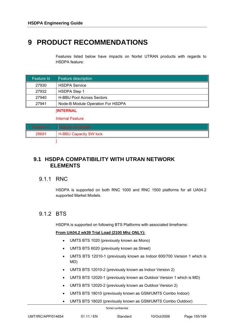
HSDPA Engineering Guide
Nortel confidential
UMT/IRC/APP/014654 01.11 / EN Standard 10/Oct/2006 Page 155/169
9 PRODUCT RECOMMENDATIONS
Features listed below have impacts on Nortel UTRAN products with regards to HSDPA feature:
Feature Id Feature description
27930 HSDPA Service 27932 HSDPA Step 1 27940 H-BBU Pool Across Sectors 27941 Node-B Module Operation For HSDPA
[INTERNAL
Internal Feature
Feature Id Feature description
28691 H-BBU Capacity SW lock
]
9.1 HSDPA COMPATIBILITY WITH UTRAN NETWORK ELEMENTS
9.1.1 RNC
HSDPA is supported on both RNC 1000 and RNC 1500 platforms for all UA04.2 supported Market Models.
9.1.2 BTS
HSDPA is supported on following BTS Platforms with associated timeframe:
From UA04.2 wk39 Trial Load (2100 Mhz ONLY):
• UMTS BTS 1020 (previously known as Mono)
• UMTS BTS 6020 (previously known as Street)
• UMTS BTS 12010-1 (previously known as Indoor 600/700 Version 1 which is MD)
• UMTS BTS 12010-2 (previously known as Indoor Version 2)
• UMTS BTS 12020-1 (previously known as Outdoor Version 1 which is MD)
• UMTS BTS 12020-2 (previously known as Outdoor Version 2)
• UMTS BTS 18010 (previously known as GSM/UMTS Combo Indoor)
• UMTS BTS 18020 (previously known as GSM/UMTS Combo Outdoor)
HSDPA Engineering Guide
Nortel confidential
UMT/IRC/APP/014654 01.11 / EN Standard 10/Oct/2006 Page 156/169
From UA04.2 CuR Load:
• All Cabinets mentioned above both into both 1900 Mhz and 2100 Mhz configurations
• UMTS BTS 6010 (previously known as Compact)
Note: HSDPA support on BTS 1120 (previously knows as Micro) is covered as part of the Micro Project itself and currently under consolidation.
[INTERNAL:
Note: The following configurations have not been tested in ISS NodeB: Mono / Compact / Street / Combo indoor and outdoor]
Furthermore the following configurations are supported, if applicable, whatever the cabinet type may be and with associated timeframe:
From UA04.2 wk39 Trial Load:
• STSR-1 and STSR-2 configurations
• OTOR-1 and OTOR-2 configurations
From UA04.2 CuR Load:
• BTBR-1 and BTBR-2 configurations
• STSR1+1 and associated depopulations (OTOR 1+1, BTBR 1+1)
NOT supported for HSDPA into UA04.2 Loads:
• OTSR configurations
• OTBR configurations
Warning: As further mentioned, in case of configurations with 2 carriers, HSDPA is ONLY supported on ONE of the two carriers for both wk39 and CuR Loads.
9.2 HSDPA COMPATIBILITY WITH MODULES
9.2.1 RNC
There are no additional requirements on RNC modules in relation with HSPDA. As such UA04.2 and products related requirements apply.
HSDPA Engineering Guide
Nortel confidential
UMT/IRC/APP/014654 01.11 / EN Standard 10/Oct/2006 Page 157/169
9.2.2 BTS
9.2.2.1 HSDPA READY MODULES
CEM module from Digital Rack is the one impacted by HSDPA from a system perspective, as such all other modules from both Digital (CCM, TRM and GPSAM), Radio Racks (DDM, MCPA…) and Antenna System are compatible with HSDPA.
Within the CEM portfolio, compatibility matrix is the following with regards to HSDPA:
• CEM alpha = NOT compatible (*)
• i Module iCEM 64 and 128 = Compatible
• I Module version 2 iCEM-2 64 and iCEM-2 128 = Compatible
(*) Warning: This does not imply that a CEM alpha cannot be plugged into a BTS with HSDPA activated, it can indeed not manage HSDPA resources but can still process dedicated and/or common channels, please refer to next sections.
9.2.2.2 BTS MODULES MIXITY
As long as minimal configuration requirements described into the section below are met, there are no specific constraints in terms of mixity in relation with HSDPA. In other words mixity allowed is the one offered so far within Nortel BTS Cabinets.
9.2.2.3 BTS MINIMAL CONFIGURATION FOR HSDPA
In order to activate HSDPA on a BTS configuration, CEM MINIMAL requirements are:
• One CEM alpha, or one iCEM (-1 / -2) 64, or one half of iCEM (-1 / -2) 128 for NON HSDPA resources.
AND
• One iCEM (-1 / -2) 64 or half or iCEM (-1 / -2) 128 for HSDPA.
9.3 HSDPA SYSTEM IMPACT
Reminder: HSDPA is an OPTIONAL feature.
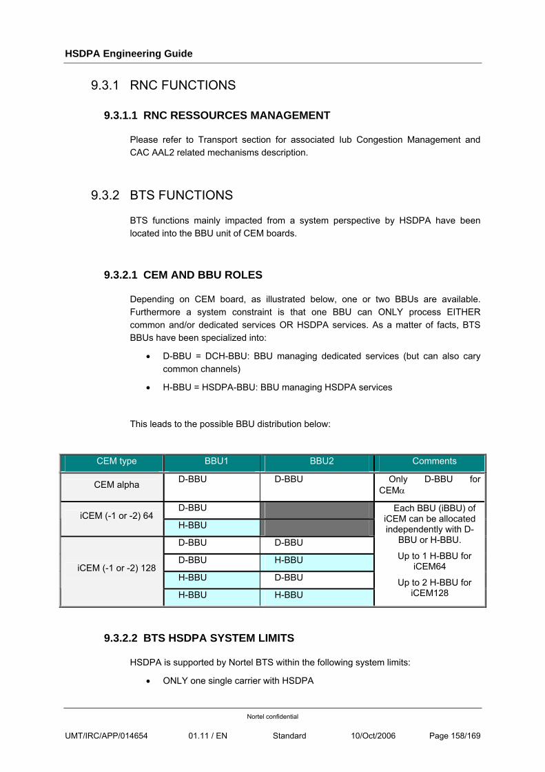
HSDPA Engineering Guide
Nortel confidential
UMT/IRC/APP/014654 01.11 / EN Standard 10/Oct/2006 Page 158/169
9.3.1 RNC FUNCTIONS
9.3.1.1 RNC RESSOURCES MANAGEMENT
Please refer to Transport section for associated Iub Congestion Management and CAC AAL2 related mechanisms description.
9.3.2 BTS FUNCTIONS
BTS functions mainly impacted from a system perspective by HSDPA have been located into the BBU unit of CEM boards.
9.3.2.1 CEM AND BBU ROLES
Depending on CEM board, as illustrated below, one or two BBUs are available. Furthermore a system constraint is that one BBU can ONLY process EITHER common and/or dedicated services OR HSDPA services. As a matter of facts, BTS BBUs have been specialized into:
• D-BBU = DCH-BBU: BBU managing dedicated services (but can also cary common channels)
• H-BBU = HSDPA-BBU: BBU managing HSDPA services
This leads to the possible BBU distribution below:
CEM type BBU1 BBU2 Comments
CEM alpha D-BBU D-BBU Only D-BBU for CEMα
D-BBU iCEM (-1 or -2) 64
H-BBU
D-BBU D-BBU
D-BBU H-BBU
H-BBU D-BBU iCEM (-1 or -2) 128
H-BBU H-BBU
Each BBU (iBBU) of iCEM can be allocated independently with D-
BBU or H-BBU.
Up to 1 H-BBU for iCEM64
Up to 2 H-BBU for iCEM128
9.3.2.2 BTS HSDPA SYSTEM LIMITS
HSDPA is supported by Nortel BTS within the following system limits:
• ONLY one single carrier with HSDPA
HSDPA Engineering Guide
Nortel confidential
UMT/IRC/APP/014654 01.11 / EN Standard 10/Oct/2006 Page 159/169
• A given HSDPA Cell is managed by one single H-BBU and cannot be split between several H-BBU
• From one to three cells per H-BBU
• Up to three H-BBU maximum per BTS
• Up to three HSDPA Cells per BTS
Warning:
Only three times one HSDPA Cells per H-BBU AND three HSDPA Cells for one H-BBU configuration have been extensively tested within Nortel R&D Labs.
[INTERNAL
It is also important to note that it is possible to scope number of HSDPA users per H-BBU as well as H-BBU maximum capacity available for HSDPA through two manufacturer parameters, respectively hsdpaMaxNumberUser (maximum number of HSDPA User per H-BBU) and hsdpaResourceMaxCapacity (Percentage of CPU that can be used per H-BBU) under BTSEquipment object.]
9.3.2.3 BBU ALLOCATION
Both D-BBU and H-BBU allocation is performed within a BTS shelf:
• At CCM Startup
• At CEM Startup if no allocation was already achieved for this CEM at CCM Startup. This covers cases where the CEM was not enabled (HW failure, Board locked) or not inserted (later CEM plug-in) at CCM Startup time.
Warning: The only context where allocation information for a CEM is cleared is when the CEM is plugged out. In order to get the allocation mechanism to be re-made is to reset the CCM, into this case all allocations are cleared and allocation algorithm is re-run.
D-BBU and H-BBU roles allocation algorithm relies on hsdpaResourceActivation and hsdpaResourceId parameters of BTSEquipment/BTSCell objects and is described here-after:
Criterias for a successful allocation are:
• At least one D-BBU
• Number of H-BBU to be allocated = Number of different hsdpaResourceId among BTS Cells with their hsdpaResourceActivation set to TRUE and within BTS HSDPA System limits.
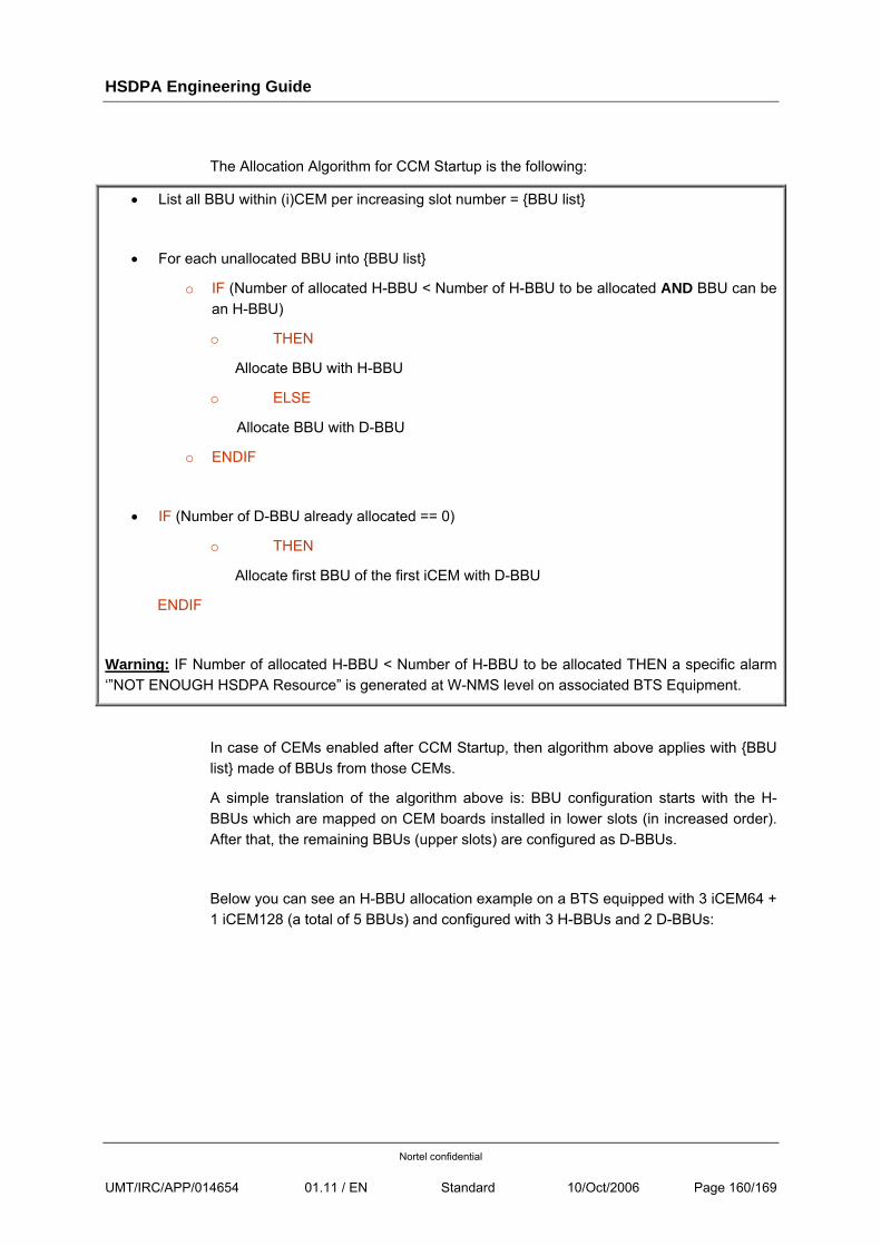
HSDPA Engineering Guide
Nortel confidential
UMT/IRC/APP/014654 01.11 / EN Standard 10/Oct/2006 Page 160/169
The Allocation Algorithm for CCM Startup is the following:
• List all BBU within (i)CEM per increasing slot number = {BBU list}
• For each unallocated BBU into {BBU list}
o IF (Number of allocated H-BBU < Number of H-BBU to be allocated AND BBU can be an H-BBU)
o THEN
Allocate BBU with H-BBU
o ELSE
Allocate BBU with D-BBU
o ENDIF
• IF (Number of D-BBU already allocated == 0)
o THEN
Allocate first BBU of the first iCEM with D-BBU
ENDIF
Warning: IF Number of allocated H-BBU < Number of H-BBU to be allocated THEN a specific alarm ‘”NOT ENOUGH HSDPA Resource” is generated at W-NMS level on associated BTS Equipment.
In case of CEMs enabled after CCM Startup, then algorithm above applies with {BBU list} made of BBUs from those CEMs.
A simple translation of the algorithm above is: BBU configuration starts with the H-BBUs which are mapped on CEM boards installed in lower slots (in increased order). After that, the remaining BBUs (upper slots) are configured as D-BBUs.
Below you can see an H-BBU allocation example on a BTS equipped with 3 iCEM64 + 1 iCEM128 (a total of 5 BBUs) and configured with 3 H-BBUs and 2 D-BBUs:
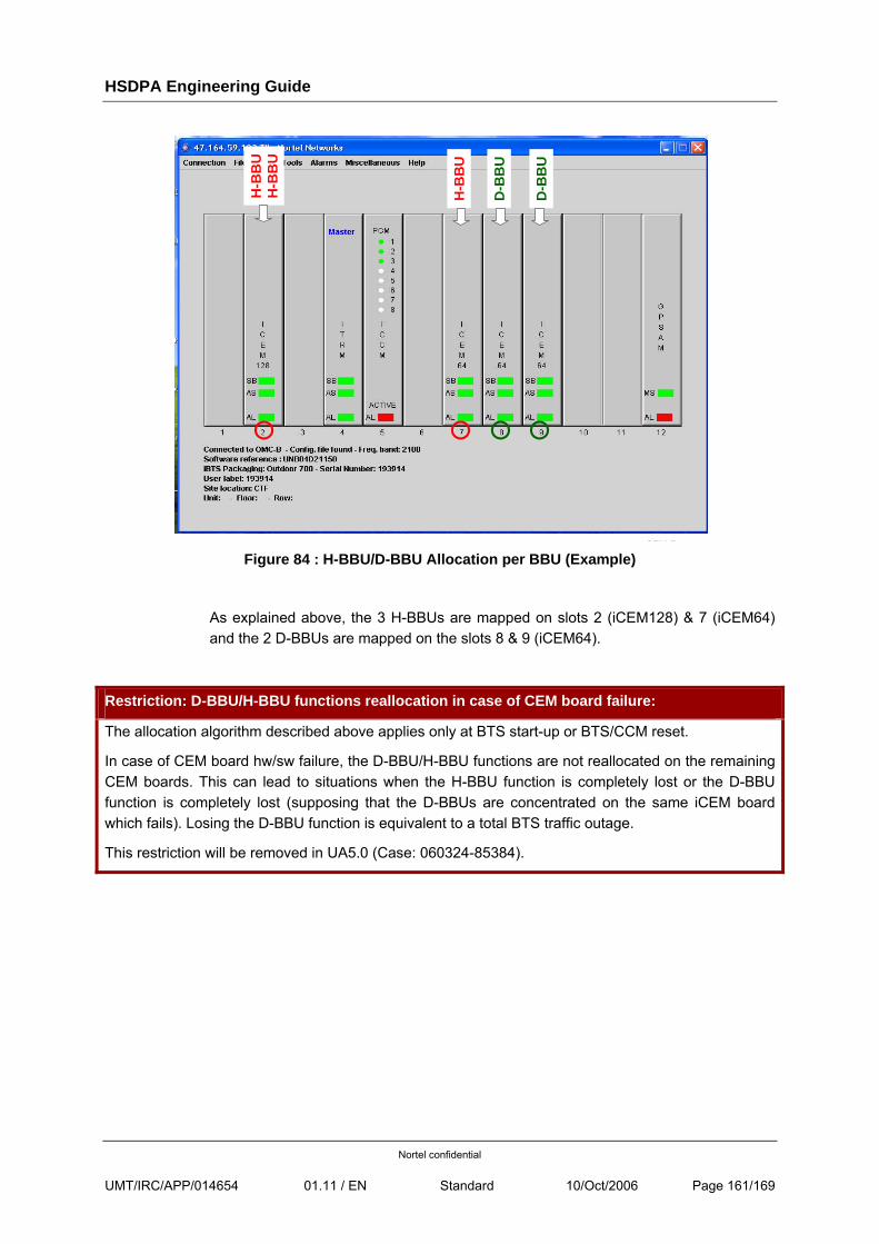
HSDPA Engineering Guide
Nortel confidential
UMT/IRC/APP/014654 01.11 / EN Standard 10/Oct/2006 Page 161/169
Figure 84 : H-BBU/D-BBU Allocation per BBU (Example)
As explained above, the 3 H-BBUs are mapped on slots 2 (iCEM128) & 7 (iCEM64) and the 2 D-BBUs are mapped on the slots 8 & 9 (iCEM64).
Restriction: D-BBU/H-BBU functions reallocation in case of CEM board failure:
The allocation algorithm described above applies only at BTS start-up or BTS/CCM reset.
In case of CEM board hw/sw failure, the D-BBU/H-BBU functions are not reallocated on the remaining CEM boards. This can lead to situations when the H-BBU function is completely lost or the D-BBU function is completely lost (supposing that the D-BBUs are concentrated on the same iCEM board which fails). Losing the D-BBU function is equivalent to a total BTS traffic outage.
This restriction will be removed in UA5.0 (Case: 060324-85384).
CEM R
H-B
BU
H-B
BU
H-B
BU
D-B
BU
D-B
BU
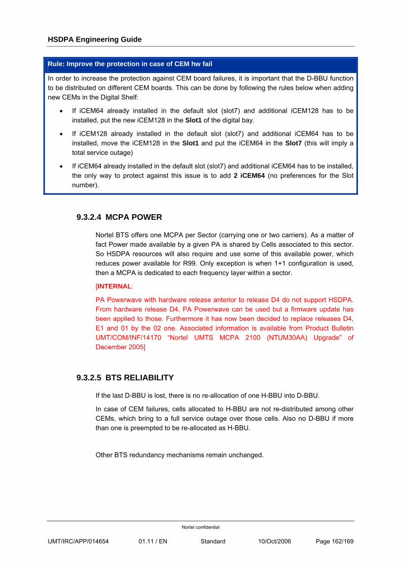
HSDPA Engineering Guide
Nortel confidential
UMT/IRC/APP/014654 01.11 / EN Standard 10/Oct/2006 Page 162/169
Rule: Improve the protection in case of CEM hw fail
In order to increase the protection against CEM board failures, it is important that the D-BBU function to be distributed on different CEM boards. This can be done by following the rules below when adding new CEMs in the Digital Shelf:
• If iCEM64 already installed in the default slot (slot7) and additional iCEM128 has to be installed, put the new iCEM128 in the Slot1 of the digital bay.
• If iCEM128 already installed in the default slot (slot7) and additional iCEM64 has to be installed, move the iCEM128 in the Slot1 and put the iCEM64 in the Slot7 (this will imply a total service outage)
• If iCEM64 already installed in the default slot (slot7) and additional iCEM64 has to be installed, the only way to protect against this issue is to add 2 iCEM64 (no preferences for the Slot number).
9.3.2.4 MCPA POWER
Nortel BTS offers one MCPA per Sector (carrying one or two carriers). As a matter of fact Power made available by a given PA is shared by Cells associated to this sector. So HSDPA resources will also require and use some of this available power, which reduces power available for R99. Only exception is when 1+1 configuration is used, then a MCPA is dedicated to each frequency layer within a sector.
[INTERNAL:
PA Powerwave with hardware release anterior to release D4 do not support HSDPA. From hardware release D4, PA Powerwave can be used but a firmware update has been applied to those. Furthermore it has now been decided to replace releases D4, E1 and 01 by the 02 one. Associated information is available from Product Bulletin UMT/COM/INF/14170 “Nortel UMTS MCPA 2100 (NTUM30AA) Upgrade” of December 2005]
9.3.2.5 BTS RELIABILITY
If the last D-BBU is lost, there is no re-allocation of one H-BBU into D-BBU.
In case of CEM failures, cells allocated to H-BBU are not re-distributed among other CEMs, which bring to a full service outage over those cells. Also no D-BBU if more than one is preempted to be re-allocated as H-BBU.
Other BTS redundancy mechanisms remain unchanged.
HSDPA Engineering Guide
Nortel confidential
UMT/IRC/APP/014654 01.11 / EN Standard 10/Oct/2006 Page 163/169
9.4 HSDPA AND UTRAN INTERFACES
9.4.1 RADIO INTERFACE
Nortel RNC supports both 2100 Mhz OR (exclusive) 1900 Mhz associated carriers.
Restriction: Wk39 Trial load:
2100 Mhz ONLY is available.
Rule: Max Number of HSDPA Carriers:
In case of configurations with two carriers, HSDPA is ONLY supported on ONE of the two carriers for both wk39 and CuR loads.
[INTERNAL:
What about Qualcomm and LGE Labs running a RNC with both 1900 and 2100 Mhz?]
9.4.2 IUB
9.4.2.1 PHYSICAL INTERFACES IMPACTS
HSDPA is supported over all available options exception made of “Multi-PCM” configuration. In case several PCM are used, IMA must be used.
9.4.2.2 ATM LAYER
From ATM connectivity point of view HSDPA impact is ad follows on a plane basis:
• Control Plane: In case all BBUs (one or two depending on CEM type and if HSDPA is applicable) of a given CEM are H-BBU, there is no need to configure one CCP for this CEM since CCP is only used for dedicated NBAP procedures.
Warning: In case one CCP has been configured for a CEM with H-BBU only, it will appear as DISABLED at the W-NMS level. Reason for this is that all UEs have a DCH part, even if they are configured in HSDPA and the H-BBU only manages the HSDPA channels (HS-PDSCH, HS-SCCH and HS-DPCCH) while the DCH part is managed by a D-BBU. So the context of the communication is located on a CEM handling the DCH part of the UE (the HSDPA may be de-configured for instance while the DCH always remain). As a matter of fact all NBAP messages intended to that UE are then sent to the VCC of the CEM managing the DCH, so no VCC needs to be allocated to a CEM that is only configured with H-BBUs.
HSDPA Engineering Guide
Nortel confidential
UMT/IRC/APP/014654 01.11 / EN Standard 10/Oct/2006 Page 164/169
• User Plane: HSDPA requires at least per BTS one dedicated ATM AAL2 VCC for User Plane associated to Qos 2.
Please refer to [R9] for further details.
9.4.3 IU-CS
Not Applicable to HSDPA context.
9.4.4 IU-PS
HSDPA does not imply new requirements from a Product and Architecture perspectives.
9.4.5 IU-R
HSDPA is not supported over IuR interfaces.
9.4.6 IU-PC
Not Applicable to HSDPA context.
HSDPA Engineering Guide
Nortel confidential
UMT/IRC/APP/014654 01.11 / EN Standard 10/Oct/2006 Page 165/169
10 ABBREVIATIONS AND DEFINITIONS
10.1 ABBREVIATIONS
AICH Acquisition Indicator Channel
AM Acknowledged Mode
AS Access Stratum
BCC Base Color Code
BCH Broadcast Channel
BSIC Base Station Identity Code
CAC Call Admission Control
CBR Constant Bit Rate
CC Call Control
CEM Channel Element Module
CN Core Network
CoS Class Of service
CP Passport: Control Processor
CPCS Common Part Convergence Sublayer
CPICH Common Pilot CHannel
CS Circuit Switched
DDM Dual Duplexer Module
DL Downlink
DPCCH Dedicated Physical Control Channel
DPDCH Dedicated Physical Data Channel
DTAP Direct Transfer Application Part
FP 3GPP: Frame Protocol
FP Passport: Function Processor
GMM GPRS Mobility Management
HCS Hierarchical Cell Structure
HSDPA High Speed Data Packet Access
HHO Hard HandOver
IE Information Element
IMEI International Mobile Equipment Identification
IMSI International Mobile Subscriber Identification
RNC-AN RNC Access Node
RNC-CN RNC Control Node
RNC-IN RNC Interface Node
ITP Initial Transmit Power
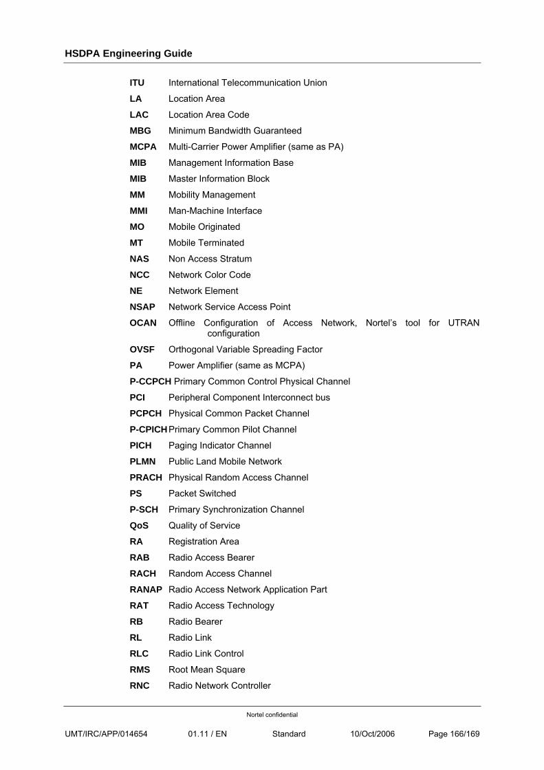
HSDPA Engineering Guide
Nortel confidential
UMT/IRC/APP/014654 01.11 / EN Standard 10/Oct/2006 Page 166/169
ITU International Telecommunication Union
LA Location Area
LAC Location Area Code
MBG Minimum Bandwidth Guaranteed
MCPA Multi-Carrier Power Amplifier (same as PA)
MIB Management Information Base
MIB Master Information Block
MM Mobility Management
MMI Man-Machine Interface
MO Mobile Originated
MT Mobile Terminated
NAS Non Access Stratum
NCC Network Color Code
NE Network Element
NSAP Network Service Access Point
OCAN Offline Configuration of Access Network, Nortel’s tool for UTRAN configuration
OVSF Orthogonal Variable Spreading Factor
PA Power Amplifier (same as MCPA)
P-CCPCH Primary Common Control Physical Channel
PCI Peripheral Component Interconnect bus
PCPCH Physical Common Packet Channel
P-CPICH Primary Common Pilot Channel
PICH Paging Indicator Channel
PLMN Public Land Mobile Network
PRACH Physical Random Access Channel
PS Packet Switched
P-SCH Primary Synchronization Channel
QoS Quality of Service
RA Registration Area
RAB Radio Access Bearer
RACH Random Access Channel
RANAP Radio Access Network Application Part
RAT Radio Access Technology
RB Radio Bearer
RL Radio Link
RLC Radio Link Control
RMS Root Mean Square
RNC Radio Network Controller
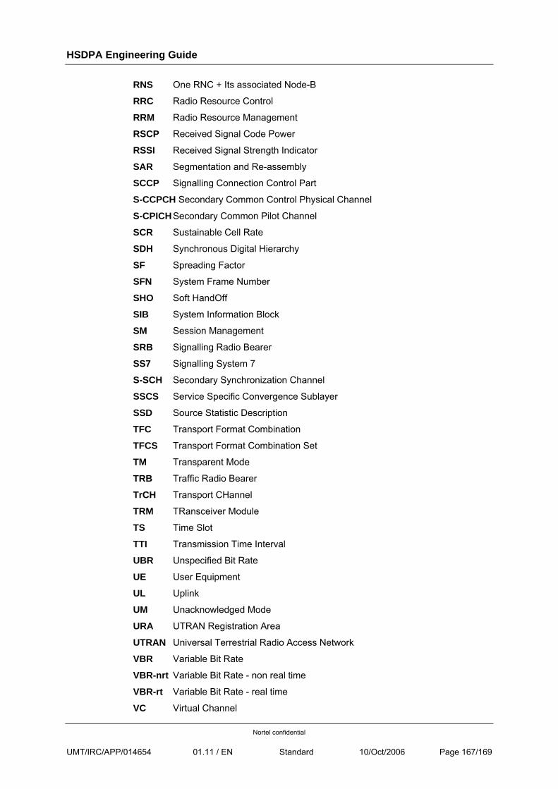
HSDPA Engineering Guide
Nortel confidential
UMT/IRC/APP/014654 01.11 / EN Standard 10/Oct/2006 Page 167/169
RNS One RNC + Its associated Node-B
RRC Radio Resource Control
RRM Radio Resource Management
RSCP Received Signal Code Power
RSSI Received Signal Strength Indicator
SAR Segmentation and Re-assembly
SCCP Signalling Connection Control Part
S-CCPCH Secondary Common Control Physical Channel
S-CPICH Secondary Common Pilot Channel
SCR Sustainable Cell Rate
SDH Synchronous Digital Hierarchy
SF Spreading Factor
SFN System Frame Number
SHO Soft HandOff
SIB System Information Block
SM Session Management
SRB Signalling Radio Bearer
SS7 Signalling System 7
S-SCH Secondary Synchronization Channel
SSCS Service Specific Convergence Sublayer
SSD Source Statistic Description
TFC Transport Format Combination
TFCS Transport Format Combination Set
TM Transparent Mode
TRB Traffic Radio Bearer
TrCH Transport CHannel
TRM TRansceiver Module
TS Time Slot
TTI Transmission Time Interval
UBR Unspecified Bit Rate
UE User Equipment
UL Uplink
UM Unacknowledged Mode
URA UTRAN Registration Area
UTRAN Universal Terrestrial Radio Access Network
VBR Variable Bit Rate
VBR-nrt Variable Bit Rate - non real time
VBR-rt Variable Bit Rate - real time
VC Virtual Channel
HSDPA Engineering Guide
Nortel confidential
UMT/IRC/APP/014654 01.11 / EN Standard 10/Oct/2006 Page 168/169
VCC Virtual Channel Connection
VCI Virtual Channel Identifier
VP Virtual Path
VPI Virtual Path Identifier
WG Wireless Gateway
10.2 DEFINITIONS
HSDPA Engineering Guide
Nortel confidential
UMT/IRC/APP/014654 01.11 / EN Standard 10/Oct/2006 Page 169/169
END OF DOCUMENT