Embed Size (px)
Citation preview

Master of Engineeringin Embedded Systems Design
UML based Process for
Embedded Systems DesignMilano
Wednesday, the 21st of May 2003
Mauro [email protected]
Master of Engineeringin Embedded Systems Design
Mauro Prevostini – UML based Process for Embedded Systems Design 2 of 117
OutlineUML meaningBenefits provided by UMLUML NotationAdvantages and disadvantages by using UMLObject Oriented Process StreamlinedCase study
Master of Engineeringin Embedded Systems Design
Mauro Prevostini – UML based Process for Embedded Systems Design 3 of 117
Bibliography[‘‘UML distilled – Applying the standard object modeling language’’, Martin Fowler with Kendall Scott, Addison Wesley Longman Inc. 1997][‘‘The Unified Modeling Language User Guide’’, G. Booch, J. Rumbaugh, I. Jacobson, Addison Wesley 1999][IVM Engineering AG, http://www.ivm.ch, Seminar 2002]

Master of Engineeringin Embedded Systems Design
Mauro Prevostini – UML based Process for Embedded Systems Design 4 of 117
OutlineUML meaningBenefits provided by UMLUML NotationAdvantages and disadvantages by using UMLObject Oriented Process StreamlinedCase study
Master of Engineeringin Embedded Systems Design
Mauro Prevostini – UML based Process for Embedded Systems Design 5 of 117
UML meaning
Master of Engineeringin Embedded Systems Design
Mauro Prevostini – UML based Process for Embedded Systems Design 6 of 117
UML: What is it ?The UML is a graphical language for:specifying, visualizing, constructing anddocumenting models of software systems, as wellas for business modeling and other non-softwaresystems.

Master of Engineeringin Embedded Systems Design
Mauro Prevostini – UML based Process for Embedded Systems Design 7 of 117
UML: What is it ?UML is a modeling language, NOT a method.Most methods consist of a modeling language and a process.The modeling language is the notation that methods use to express design.The process is their advice on what steps to take in doing a design.
Master of Engineeringin Embedded Systems Design
Mauro Prevostini – UML based Process for Embedded Systems Design 8 of 117
OutlineUML meaningBenefits provided by UMLUML NotationAdvantages and disadvantages by using UMLObject Oriented Process StreamlinedCase study
Master of Engineeringin Embedded Systems Design
Mauro Prevostini – UML based Process for Embedded Systems Design 9 of 117
UML benefits overview
It lowers costs of training and retooling when changing between projects and organizations.It provides new integration opportunity between tools, processes and domains.It enables developers to focus on delivering business value and provides them a paradigm to accomplish this.

Master of Engineeringin Embedded Systems Design
Mauro Prevostini – UML based Process for Embedded Systems Design 10 of 117
UML benefits in Embedded Systems DesignIt is technology independent.It is Hardware/Software partitioning independent.It allows specification of both functional and non-functional requirements and constraints.It allows highly modular systems design.
Master of Engineeringin Embedded Systems Design
Mauro Prevostini – UML based Process for Embedded Systems Design 11 of 117
OutlineUML meaningBenefits provided by UMLUML NotationAdvantages and disadvantages by using UMLObject Oriented Process StreamlinedCase study
Master of Engineeringin Embedded Systems Design
Mauro Prevostini – UML based Process for Embedded Systems Design 12 of 117
Diagram OverviewStructural diagrams
Used to visualize, specify, construct, document staticstatic system aspects
Behavioural diagramsUsed to visualize, specify, construct, document dynamicdynamic system aspects

Master of Engineeringin Embedded Systems Design
Mauro Prevostini – UML based Process for Embedded Systems Design 13 of 117
Diagram OverviewStructural diagrams
Used to visualize, specify, construct, document staticstatic system aspects
Behavioural diagramsUsed to visualize, specify, construct, document dynamicdynamic system aspects
Master of Engineeringin Embedded Systems Design
Mauro Prevostini – UML based Process for Embedded Systems Design 14 of 117
Structural DiagramClass diagramsPackage diagramsObject diagramsComponent diagramsDeployment diagrams
Master of Engineeringin Embedded Systems Design
Mauro Prevostini – UML based Process for Embedded Systems Design 15 of 117
Class: definitionA classclass is a description of a set of objects that share the same attributes, operations, relationships and semantics.An attributeattribute is a named property of a class that describes a range of values that instances of the property may hold.An operation operation is a service that can be requested from an object to affect behaviour.

Master of Engineeringin Embedded Systems Design
Mauro Prevostini – UML based Process for Embedded Systems Design 16 of 117
Class: notation
Name
Attributes
Operations
Master of Engineeringin Embedded Systems Design
Mauro Prevostini – UML based Process for Embedded Systems Design 17 of 117
RelationsConnections between classes:
DependencyGeneralizationAssociation
Master of Engineeringin Embedded Systems Design
Mauro Prevostini – UML based Process for Embedded Systems Design 18 of 117
DependencyA dependency exists between two elements if changes to the definition of one element may cause changes to the other.
Example: One class mentions another as a parameter to an operation.
Window
handleEvent()Event

Master of Engineeringin Embedded Systems Design
Mauro Prevostini – UML based Process for Embedded Systems Design 19 of 117
GeneralizationA generalization is a relationship between ageneral thing (superclass or parent) and a morespecific thing (subclass or child).
Shape
Circle Rectangle
Master of Engineeringin Embedded Systems Design
Mauro Prevostini – UML based Process for Embedded Systems Design 20 of 117
AssociationAn association is a relationship between instances of classes or between objects.
Example: A person works for a company(An association between objects is called a link.)
Person Company
Master of Engineeringin Embedded Systems Design
Mauro Prevostini – UML based Process for Embedded Systems Design 21 of 117
Association AdornmentsNameRoleMultiplicityAggregationComposition
Master of Engineeringin Embedded Systems Design
Mauro Prevostini – UML based Process for Embedded Systems Design 22 of 117
Name, Role, Multiplicity
Person Companyworks for
Person Companyemployee
employer
Person Company1..*
1
Master of Engineeringin Embedded Systems Design
Mauro Prevostini – UML based Process for Embedded Systems Design 23 of 117
AggregationAggregation is a relationship where one classrepresents a larger thing that consists of smallerthings.
Company
Department
Master of Engineeringin Embedded Systems Design
Mauro Prevostini – UML based Process for Embedded Systems Design 24 of 117
CompositionComposition is a special form of aggregationwhere the parts are inseparable from the whole.
Window
Frame

Master of Engineeringin Embedded Systems Design
Mauro Prevostini – UML based Process for Embedded Systems Design 25 of 117
InterfaceAn interface is a named collection of operations used tospecify a service of a class without dictating itsimplementation. An interface may participate ingeneralization, association and dependency relationships.
Observer
‘‘interface’’Observer
update()
Master of Engineeringin Embedded Systems Design
Mauro Prevostini – UML based Process for Embedded Systems Design 26 of 117
RealizationA realization is a relationship between an interface and theclass that provides the interface’s services.A class may realize many interfaces.
‘‘interface’’Observer
update()
TargetTracker
Master of Engineeringin Embedded Systems Design
Mauro Prevostini – UML based Process for Embedded Systems Design 27 of 117
Adornments and ExtensibilityNotes
A note is a graphical symbol containing text and/or graphics that offer(s) some comment or detail about an element within a model.
StereotypesA stereotype is an extension of the vocabulary of the UML that allows you to create a new kind of ‘‘building block’’ that’s specific to the problem you’re trying to solve.
Tagged ValuesA tagged value is an extension of the properties of a model element that allows you to create new information within the specification of that element.
ConstraintsA constraint is an extension of the semantics of one or more model elements which specifies a condition that must be true

Master of Engineeringin Embedded Systems Design
Mauro Prevostini – UML based Process for Embedded Systems Design 28 of 117
PackageA package is a general-purpose mechanism for organizing elements of a model such as classes or diagrams, into groups.Every element within a model is uniquely owned by one package. Also, that element’s name must be unique within that package.
Master of Engineeringin Embedded Systems Design
Mauro Prevostini – UML based Process for Embedded Systems Design 29 of 117
Package Notation
GameLogic
Controller PlayField Player Rule
Game
GUI Logic Data Package of packages
Master of Engineeringin Embedded Systems Design
Mauro Prevostini – UML based Process for Embedded Systems Design 30 of 117
Object Diagrams
An object diagram shows a set of objects, and their relationships, at a specific point in time.
c: University
name = ‘‘usi’’
d1: Institute
name = ‘‘alari’’
: Contact Info
phone = ‘‘706’’
p1: Person
ID = ‘‘bondi’’

Master of Engineeringin Embedded Systems Design
Mauro Prevostini – UML based Process for Embedded Systems Design 31 of 117
ComponentsComponents represents physical modules of code.Examples:
Dynamic Link Library (DLL)COM componentExecutable (EXE)
Master of Engineeringin Embedded Systems Design
Mauro Prevostini – UML based Process for Embedded Systems Design 32 of 117
Component notation
« exe »
Master of Engineeringin Embedded Systems Design
Mauro Prevostini – UML based Process for Embedded Systems Design 33 of 117
DeploymentA deployment diagram shows the physical relationships among Software and Hardware components in the delivered system.
Client
Serverhttp

Master of Engineeringin Embedded Systems Design
Mauro Prevostini – UML based Process for Embedded Systems Design 34 of 117
Diagram OverviewStructural diagrams
Used to visualize, specify, construct, document staticstatic system aspects
Behavioural diagramsUsed to visualize, specify, construct, document dynamicdynamic system aspects
Master of Engineeringin Embedded Systems Design
Mauro Prevostini – UML based Process for Embedded Systems Design 35 of 117
Behavioural DiagramsUse Case diagramsSequence diagramsCollaboration diagramsStatechart diagramsActivity diagrams
Master of Engineeringin Embedded Systems Design
Mauro Prevostini – UML based Process for Embedded Systems Design 36 of 117
Use CaseThe use case is a typical interaction between a user and a computer system.The use case captures some user-visible function.You capture a use case by talking to your typical users and discussing the various thing they might do with the system.

Master of Engineeringin Embedded Systems Design
Mauro Prevostini – UML based Process for Embedded Systems Design 37 of 117
ActorAn actor is a role that a user plays with respect to the system.A single actor may perform many use casesA use case may have several actors performing it.An actor could be also a non-human player, e.g:
a software or hardware componenteven a component of the system you have to describe (sensors, motors, etc.)
Master of Engineeringin Embedded Systems Design
Mauro Prevostini – UML based Process for Embedded Systems Design 38 of 117
Use Case Diagram Notation
Send Data
WMR
Read Data
Master of Engineeringin Embedded Systems Design
Mauro Prevostini – UML based Process for Embedded Systems Design 39 of 117
Sequence DiagramA sequence diagram is an interaction diagram that emphasizes the time ordering of messages.
: WMR Counter
Read data
Store data
Lifeline: it represents the lifetime of an object
Focus of control: it shows the period of time duringwhich an object is performing an action.
Master of Engineeringin Embedded Systems Design
Mauro Prevostini – UML based Process for Embedded Systems Design 40 of 117
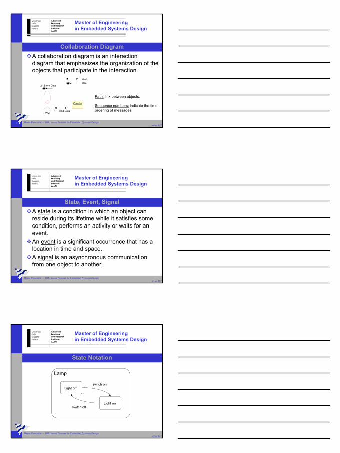
Collaboration DiagramA collaboration diagram is an interaction diagram that emphasizes the organization of the objects that participate in the interaction.
: WMR
Counter
1: Read Data
2: Store Data
startstop
Path: link between objects.
Sequence numbers: indicate the timeordering of messages.
Master of Engineeringin Embedded Systems Design
Mauro Prevostini – UML based Process for Embedded Systems Design 41 of 117
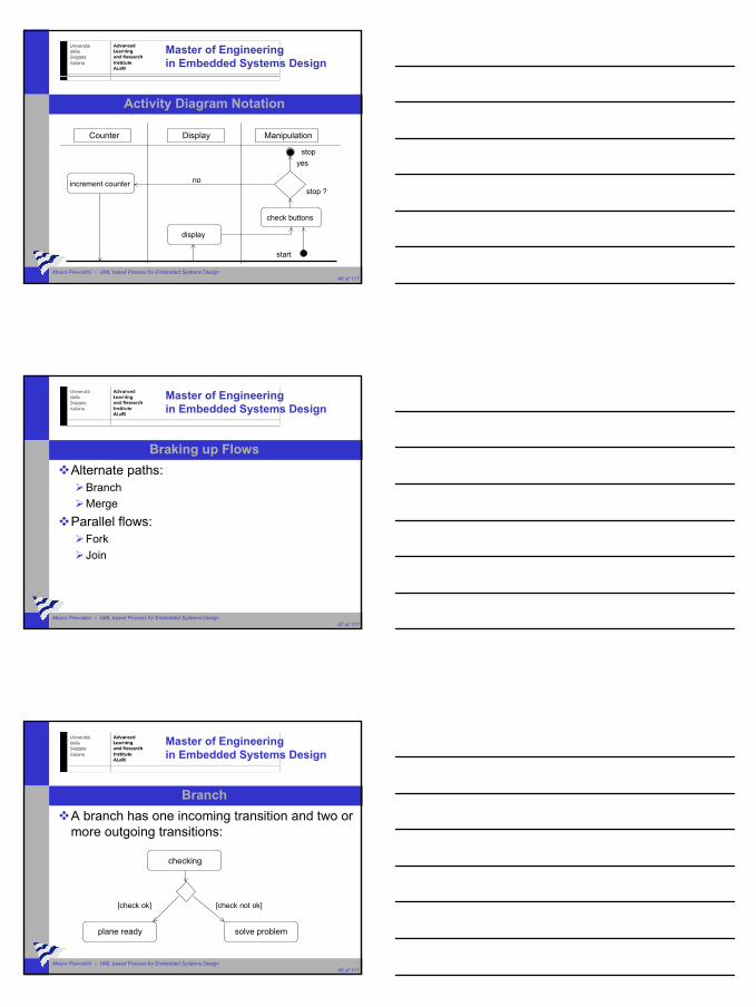
State, Event, SignalA state is a condition in which an object can reside during its lifetime while it satisfies some condition, performs an activity or waits for an event.An event is a significant occurrence that has a location in time and space.A signal is an asynchronous communication from one object to another.
Master of Engineeringin Embedded Systems Design
Mauro Prevostini – UML based Process for Embedded Systems Design 42 of 117
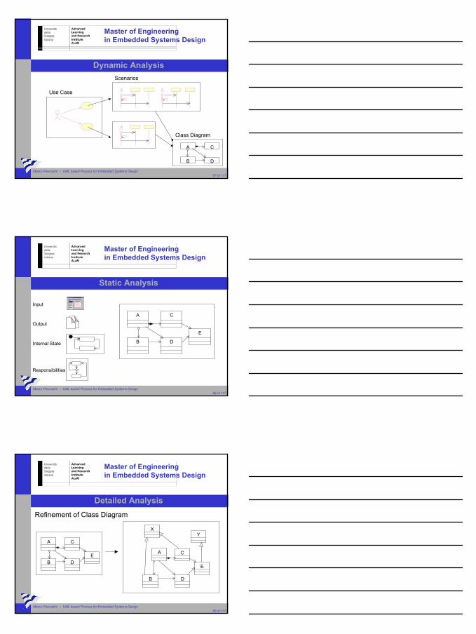
State Notation
Lamp
Light off
Light on
switch on
switch off

Master of Engineeringin Embedded Systems Design
Mauro Prevostini – UML based Process for Embedded Systems Design 43 of 117
State MachineA state machine is a behaviour that specifies the sequences of states that an object goes through in its lifetime, in response to events, and in its responses to those events.
Master of Engineeringin Embedded Systems Design
Mauro Prevostini – UML based Process for Embedded Systems Design 44 of 117
Initial and Final StatesThe initial state is the default starting place for a state machine.The final state indicates the completion of the state machine’s execution.
Master of Engineeringin Embedded Systems Design
Mauro Prevostini – UML based Process for Embedded Systems Design 45 of 117
Activity DiagramsAn activity diagram, which it’s similar to a flowchart, is useful for modeling workflows and the details of operations.
Activity vs Interaction Diagrams:The interaction diagram looks at the objects that pass messages.The activity diagram looks at the operations that are passed among objects.
Master of Engineeringin Embedded Systems Design
Mauro Prevostini – UML based Process for Embedded Systems Design 46 of 117
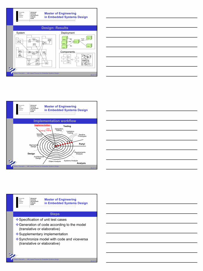
Activity Diagram Notation
Counter Display Manipulation
display
check buttons
start
stopyes
increment counter nostop ?
Master of Engineeringin Embedded Systems Design
Mauro Prevostini – UML based Process for Embedded Systems Design 47 of 117
Braking up FlowsAlternate paths:
BranchMerge
Parallel flows:ForkJoin
Master of Engineeringin Embedded Systems Design
Mauro Prevostini – UML based Process for Embedded Systems Design 48 of 117
BranchA branch has one incoming transition and two or more outgoing transitions:
checking
plane ready
[check ok]
solve problem
[check not ok]

Master of Engineeringin Embedded Systems Design
Mauro Prevostini – UML based Process for Embedded Systems Design 49 of 117
MergeA merge has two or more incoming transitions and one outgoing transition:
departure
plane ready passengers boarded
Master of Engineeringin Embedded Systems Design
Mauro Prevostini – UML based Process for Embedded Systems Design 50 of 117
ForkA fork represents the splitting of a single flow of control into two or more concurrent flows of control:
receive event
log event process event
Master of Engineeringin Embedded Systems Design
Mauro Prevostini – UML based Process for Embedded Systems Design 51 of 117
JoinA join represents the synchronization of two or more flows of control into one sequential flow of control:
pay bill
receive product bill customer

Master of Engineeringin Embedded Systems Design
Mauro Prevostini – UML based Process for Embedded Systems Design 52 of 117
OutlineUML meaningBenefits provided by UMLUML NotationAdvantages and disadvantages by using UMLObject Oriented Process StreamlinedCase study
Master of Engineeringin Embedded Systems Design
Mauro Prevostini – UML based Process for Embedded Systems Design 53 of 117
Advantages by using UMLHelp in acquiring an overall view of the systemHelp in visualizing, specifying, constructing and documenting a hardware/software systemClarity: reference to its semanticsConsistency Check:
Implementation vs designDesign vs specifications
Easy to add new features
Master of Engineeringin Embedded Systems Design
Mauro Prevostini – UML based Process for Embedded Systems Design 54 of 117
Disadvantages by using UMLFormalization hard to deal with for non-expert usersToo detailed formalization could create confusion between project stakeholders

Master of Engineeringin Embedded Systems Design
Mauro Prevostini – UML based Process for Embedded Systems Design 55 of 117
Future perspectivesUML System-level specification
HW/SW CodesignVHDL code generation
Master of Engineeringin Embedded Systems Design
Mauro Prevostini – UML based Process for Embedded Systems Design 56 of 117
LinksObject Manaement Group:
http://www.omg.org
UML V2.0:http://www.u2-partners.org
A UML Tutorialhttp://odl-skopje.etf.ukim.edu.mk/uml-help
Master of Engineeringin Embedded Systems Design
Mauro Prevostini – UML based Process for Embedded Systems Design 57 of 117
OutlineUML meaningBenefits provided by UMLUML NotationAdvantages and disadvantages by using UMLObject Oriented Process StreamlinedCase study

Master of Engineeringin Embedded Systems Design
Mauro Prevostini – UML based Process for Embedded Systems Design 58 of 117
Object Oriented Process StreamlinedProcessesAnalysisDesignImplementationTesting
Master of Engineeringin Embedded Systems Design
Mauro Prevostini – UML based Process for Embedded Systems Design 59 of 117
Processes: The spiral modelImplementation
RequirementsAnalysis
Object Analysis
ArchitecturalDesign
MechanisticDesign
DetailedDesign
Design
Testing
Party!
IntegrationTesting Validation
TestingCoding
UnitTesting
IterativePrototypes
Systems AnalysisAnalysis
Master of Engineeringin Embedded Systems Design
Mauro Prevostini – UML based Process for Embedded Systems Design 60 of 117
The spiral modelAll workflows are executed repeatedly in sequence.High risk parts are implemented first.New requirements may be built in at any time.The system grows incrementally by iterative prototypes.

Master of Engineeringin Embedded Systems Design
Mauro Prevostini – UML based Process for Embedded Systems Design 61 of 117
Processes: Phases / MilestonesLifecycle decomposed over time into four sequential phases.Each concluded by a major milestone.
Inception Elaboration Construction Transition
time
Lifecycleobjectivesmilestone
Lifecyclearchitecturemilestone
Initial operationalcapabilitymilestone
Productreleasemilestone
Master of Engineeringin Embedded Systems Design
Mauro Prevostini – UML based Process for Embedded Systems Design 62 of 117
Processes: Vertical Prototyping
The lifecycle for the Rational Unified Process (RUP).
Structure:horizontally
Implementation:vertically
Master of Engineeringin Embedded Systems Design
Mauro Prevostini – UML based Process for Embedded Systems Design 63 of 117
Analysis workflow
RequirementsAnalysis
Object Analysis
ArchitecturalDesign
MechanisticDesign
DetailedDesign
Design
Testing
Party!
IntegrationTesting Validation
TestingCoding
UnitTesting
IterativePrototypes
Systems AnalysisAnalysis
Implementation

Master of Engineeringin Embedded Systems Design
Mauro Prevostini – UML based Process for Embedded Systems Design 64 of 117
NotationUse Case DiagramSequence DiagramCollaboration DiagramStatechart DiagramActivity Diagram
Master of Engineeringin Embedded Systems Design
Mauro Prevostini – UML based Process for Embedded Systems Design 65 of 117
StepsDynamic Analysis (Behavioural)
ActorUse CaseRelation between actor and Use CaseScenariosDetailed Analysis of scenarios
Static Analysis (Structural)Objects / ClassesValues (attributes)Behaviour (methods)Responsibilities (activities)
Master of Engineeringin Embedded Systems Design
Mauro Prevostini – UML based Process for Embedded Systems Design 66 of 117
StepsDetailed Analysis
Class HierarchyRefinement of Class DiagramsRefinement of Statechart DiagramsRefinement of Activity DiagramRefinement of Scenarios
Master of Engineeringin Embedded Systems Design
Mauro Prevostini – UML based Process for Embedded Systems Design 67 of 117
Dynamic Analysis
Use Case
Scenarios
A C
DB
Class Diagram
Master of Engineeringin Embedded Systems Design
Mauro Prevostini – UML based Process for Embedded Systems Design 68 of 117
Static Analysis
Input
Output
Internal State
Responsibilities
A
B
C
D
E
Master of Engineeringin Embedded Systems Design
Mauro Prevostini – UML based Process for Embedded Systems Design 69 of 117
Detailed AnalysisRefinement of Class Diagram
A
B
C
DE
A
B
C
D
E
XY

Master of Engineeringin Embedded Systems Design
Mauro Prevostini – UML based Process for Embedded Systems Design 70 of 117
Analysis: ResultsUse Case
Scenarios
Test
State ChartActivity
A
B
C
D
E
XY
Class Diagram
Master of Engineeringin Embedded Systems Design
Mauro Prevostini – UML based Process for Embedded Systems Design 71 of 117
Design workflow
RequirementsAnalysis
Object Analysis
ArchitecturalDesign
MechanisticDesign
DetailedDesign
Design
Testing
Party!
IntegrationTesting Validation
TestingCoding
UnitTesting
IterativePrototypes
Systems AnalysisAnalysis
Implementation
Master of Engineeringin Embedded Systems Design
Mauro Prevostini – UML based Process for Embedded Systems Design 72 of 117
NotationClass DiagramPackage DiagramComponent DiagramDeployment Diagram

Master of Engineeringin Embedded Systems Design
Mauro Prevostini – UML based Process for Embedded Systems Design 73 of 117
StepsArchitecture
Defining packagesInterfaces between packagesModels, Frameworks, Libraries
Error HandlingDifferent error handling modelsConsequent error handling
InitializationCreation of system objects (factory)Initialization of objectsError handling during initialization
Master of Engineeringin Embedded Systems Design
Mauro Prevostini – UML based Process for Embedded Systems Design 74 of 117
StepsComponents
Separation into code units applying certain criteriasComponents contain a certain number of classesExecutablesLibrariesDLL’s
DeploymentPhysical system image depending on certain criteriaPartitioning Components – Software, Hardware
Master of Engineeringin Embedded Systems Design
Mauro Prevostini – UML based Process for Embedded Systems Design 75 of 117
Definition of Packages
A
B
C
DE
X Y
Class Diagram
A C
B D
EY
X
Package Diagram

Master of Engineeringin Embedded Systems Design
Mauro Prevostini – UML based Process for Embedded Systems Design 76 of 117
Interfaces
A C
B D
EY
X
Package DiagramA
C
BD
E
Y
X I1
I2
I3
I1, I2, I3: Interfaces
Master of Engineeringin Embedded Systems Design
Mauro Prevostini – UML based Process for Embedded Systems Design 77 of 117
Models
AC
B D
E
Y
X I1
I2
I3I1, I2, I3: Interfaces
AC
BD
E
Y
X I1
I2
I3
M1, M2: Models
M1
M2
Master of Engineeringin Embedded Systems Design
Mauro Prevostini – UML based Process for Embedded Systems Design 78 of 117
Error Handling
AC
B D
E
Y
X I1
I2
I3M1, M2: Models
M1
M2
AC
BD
E
Y
X I1
I2
I3
M1
M2I4
ERR

Master of Engineeringin Embedded Systems Design
Mauro Prevostini – UML based Process for Embedded Systems Design 79 of 117
Initialization / Instantiation
AC
B D
E
Y
X I1
I2
I3
M1
M2I4
ERR
AC
BD
E
Y
X I1
I2
I3
M1
M2
I4ERR
U
U2
U3
U1
Initialization states are very important ! (i.e. Factory)
Master of Engineeringin Embedded Systems Design
Mauro Prevostini – UML based Process for Embedded Systems Design 80 of 117
Components
X
M1
M2
*.dllA
C
BD
E
Y
I1
I2
I3
I4ERR
U
U2
U3
U1
*.exe
Master of Engineeringin Embedded Systems Design
Mauro Prevostini – UML based Process for Embedded Systems Design 81 of 117
Deployment
Client
Client
Client
Server
Printer
Printer
http
http
http
Parallelcable
Master of Engineeringin Embedded Systems Design
Mauro Prevostini – UML based Process for Embedded Systems Design 82 of 117
Design: Results
AC
BD
E
Y
X I1
I2
I3
M1
M2
I4
ERR
U
U2
U3
U1
System
Client
Client
Client
Server
Printer
Printer
http Parallelcable
http
http
Deployment
Components
Master of Engineeringin Embedded Systems Design
Mauro Prevostini – UML based Process for Embedded Systems Design 83 of 117
Implementation workflowImplementation
RequirementsAnalysis
Object Analysis
ArchitecturalDesign
MechanisticDesign
DetailedDesign
Design
Testing
Party!
IntegrationTesting Validation
TestingCoding
UnitTesting
IterativePrototypes
Systems AnalysisAnalysis
Master of Engineeringin Embedded Systems Design
Mauro Prevostini – UML based Process for Embedded Systems Design 84 of 117
StepsSpecification of unit test casesGeneration of code according to the model(translative or elaborative)Supplementary implementationSynchronize model with code and viceversa(translative or elaborative)
Master of Engineeringin Embedded Systems Design
Mauro Prevostini – UML based Process for Embedded Systems Design 85 of 117
StepsGeneration of componentsVerify the implemented code (metrics)Installation conceptsCreation of technical documentationUnit test cases execution
Master of Engineeringin Embedded Systems Design
Mauro Prevostini – UML based Process for Embedded Systems Design 86 of 117
Implementation: Results Source code of the systemComponents according to the component diagramInstallers of the different component (only for SW)Technical Reference ManualUnit Test CasesSystem synchronization of model with implementation
Master of Engineeringin Embedded Systems Design
Mauro Prevostini – UML based Process for Embedded Systems Design 87 of 117
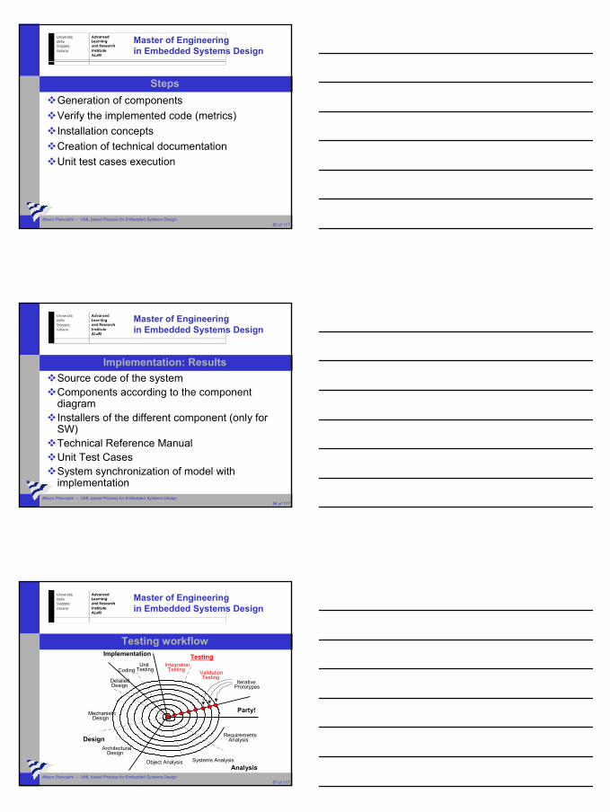
Testing workflowImplementation
RequirementsAnalysis
Object Analysis
ArchitecturalDesign
MechanisticDesign
DetailedDesign
Design
Testing
Party!
IntegrationTesting Validation
TestingCoding
UnitTesting
IterativePrototypes
Systems AnalysisAnalysis
Master of Engineeringin Embedded Systems Design
Mauro Prevostini – UML based Process for Embedded Systems Design 88 of 117
StepsCreation of a reproducible test environmentSpecification of integration and system test cases:
based on analysis, design and implementation criterias:specification of functional, usability, reliability and performance test cases
User Guide consistency checkInstallation Manual consistency checkScripts fo test automation(regression testing)
Master of Engineeringin Embedded Systems Design
Mauro Prevostini – UML based Process for Embedded Systems Design 89 of 117
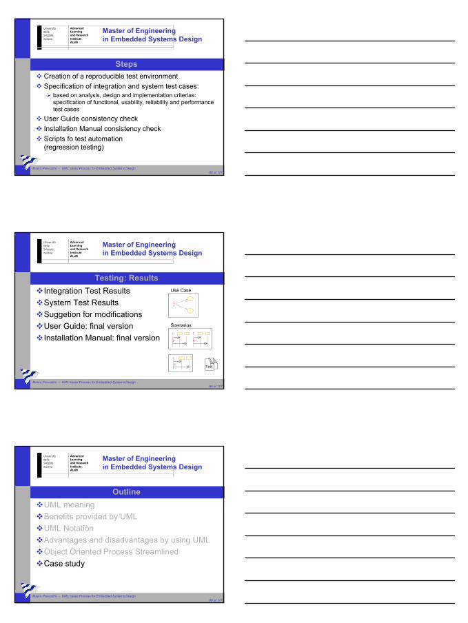
Testing: ResultsIntegration Test ResultsSystem Test ResultsSuggetion for modificationsUser Guide: final versionInstallation Manual: final version
Use Case
Scenarios
Test
Master of Engineeringin Embedded Systems Design
Mauro Prevostini – UML based Process for Embedded Systems Design 90 of 117
OutlineUML meaningBenefits provided by UMLUML NotationAdvantages and disadvantages by using UMLObject Oriented Process StreamlinedCase study
Master of Engineeringin Embedded Systems Design
“System-Level Design of Embedded Applications by UML,
the wireless meter reading case”
Srinivas Mankan, Aris Martinola, Antonio Minosi, Mauro Prevostini
Master of Engineeringin Embedded Systems Design
Mauro Prevostini – UML based Process for Embedded Systems Design 92 of 117
Cooperation with partnersThe project has been supported by:
And presented at:
Master of Engineeringin Embedded Systems Design
Mauro Prevostini – UML based Process for Embedded Systems Design 93 of 117
Project Goals
Figure out one possible implementation of the Wireless Meter Reading (WMR) system.Use the Unified Modeling Language (UML) for analysing and modeling the hardware-software systems.Simulate data transmission between the different protocols involved in the WMR.

Master of Engineeringin Embedded Systems Design
Mauro Prevostini – UML based Process for Embedded Systems Design 94 of 117
Outline
Problem DescriptionDevelopment Process OverviewUML Formalization
Master of Engineeringin Embedded Systems Design
Mauro Prevostini – UML based Process for Embedded Systems Design 95 of 117
Outline
Problem DescriptionDevelopment Process OverviewUML Formalization
Master of Engineeringin Embedded Systems Design
Mauro Prevostini – UML based Process for Embedded Systems Design 96 of 117
Problem DescriptionWireless Meter Reading (WMR) as a reading system to help Service Providers:
to get consumer consumption data regarding gas, electricity and water automatically via wireless technology.
WMR must be a low-power and low-cost device.

Master of Engineeringin Embedded Systems Design
Mauro Prevostini – UML based Process for Embedded Systems Design 97 of 117
ObjectivesReal-Time determination of energy consumption Use wireless technology.Security: authentication and data integrityBenefits:
Realtime billingOperational costs minimizationTheft monitoring
Master of Engineeringin Embedded Systems Design
Mauro Prevostini – UML based Process for Embedded Systems Design 98 of 117
Outline
Problem DescriptionDevelopment Process OverviewUML Formalization
Master of Engineeringin Embedded Systems Design
Mauro Prevostini – UML based Process for Embedded Systems Design 99 of 117
Development Process
Inception Phase (Requirements Specification)Elaboration Phase (Requirements Analysis & Design)Implementation Phase (System Simulation)Test & Validation Phase (To be performed)
Master of Engineeringin Embedded Systems Design
Mauro Prevostini – UML based Process for Embedded Systems Design 100 of 117
Development Process
Inception Phase (Requirements Specification)specification of the project vision;develop an Operational Concept Description (OCD) document;gather companies feedbacks/reviews on the OCD document.
Elaboration Phase (Requirements Analysis & Design)Implementation Phase (System Simulation)Test & Validation Phase (To be performed)
Master of Engineeringin Embedded Systems Design
Mauro Prevostini – UML based Process for Embedded Systems Design 101 of 117
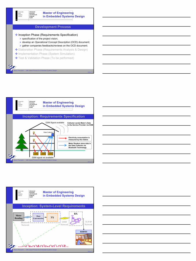
Inception: Requirements Specification
GSM signal not available
GSM Signal available
1234 1234 1234
Electricity consumption ismeasured by the meters
Meter Readers store data inthe Data Collector via Bluetooth Technology
Data Collector
Collector sends Meter’s Datato the Service Provider via GSM
Master of Engineeringin Embedded Systems Design
Mauro Prevostini – UML based Process for Embedded Systems Design 102 of 117
Inception: System-Level Requirements
GSMNetwork
DataConcentrator TX
MeterReading
RX
RDBMS
TCP/IPNetwork
BluetoothNetwork

Master of Engineeringin Embedded Systems Design
Mauro Prevostini – UML based Process for Embedded Systems Design 103 of 117
Development Process
Inception Phase (Requirements Specification)Elaboration Phase (Requirements Analysis & Design)
planning the necessary activities;analysing the system requirements;specifying the system architecture.
Implementation Phase (System Simulation)Test & Validation Phase - (To be performed)
Master of Engineeringin Embedded Systems Design
Mauro Prevostini – UML based Process for Embedded Systems Design 104 of 117
Requirements Analysis & Design
GSMNetwork
DataCollector TX
MeterReading
RX
RDBMS
TCP/IPNetwork
BluetoothNetwork
Master of Engineeringin Embedded Systems Design
Mauro Prevostini – UML based Process for Embedded Systems Design 105 of 117
Outline
Problem DescriptionDevelopment Process OverviewUML Formalization

Master of Engineeringin Embedded Systems Design
Mauro Prevostini – UML based Process for Embedded Systems Design 106 of 117
Analysis workflow
RequirementsAnalysis
Object Analysis
ArchitecturalDesign
MechanisticDesign
DetailedDesign
Design
Testing
Party!
IntegrationTesting Validation
TestingCoding
UnitTesting
IterativePrototypes
Systems AnalysisAnalysis
Implementation
Master of Engineeringin Embedded Systems Design
Mauro Prevostini – UML based Process for Embedded Systems Design 107 of 117
StepsDynamic Analysis (Behavioural)
ActorUse CaseRelation between actor and Use CaseScenariosDetailed Analysis of scenarios
Master of Engineeringin Embedded Systems Design
Mauro Prevostini – UML based Process for Embedded Systems Design 108 of 117
Dynamic Analysis
Use Case
Scenarios
A C
DB
Class Diagram

Master of Engineeringin Embedded Systems Design
Mauro Prevostini – UML based Process for Embedded Systems Design 109 of 117
Case StudyScopo dello studio di caso è di formalizzare tramite UML le seguenti specifiche di un
lettore di contatori wireless (WMR = Wireless Meter Reader).
Il WMR è un dispositivo a bassa potenza che misura i dati relativi al consumo di elettricità, gas e acqua. L’operazione avviene ogni 15 minuti. Una volta al giorno il WMR spedisce i dati al concentratore (DC = Data Concentrator) attraverso un collegamento senza fili (ad esempio Bluetooth). Se il DC non riesce ad elaborare il messaggio spedito dal WMR, la comunicazione viene abbandonata dopo un timeoutpredefinito. Uno dei compiti del DC è verificare l’integrità dei dati. In caso di errori il DC spedisce una richiesta di ritrasmissione al WMR. In seguito il DC memorizza i dati in un buffer locale.Una volta al mese i dati vengono spediti mediante rete wireless (ad esempio via GSM) alla centrale della società erogatrice dove vengono verificati e, in caso di errori, verrà spedita una richiesta di ritrasmissioneal DC. Al termine del procedimento di verifica, i dati vengono depositati nella banca dati locale.La società erogatrice inoltre deve poter leggere in qualsiasi momento sia i dati depositati nel DC sia, in tempo reale, i dati del contatore.
![5 Process Modeling using UML - University of Leicester · 2 PROCESS MODELING USING UML version UML 1.3 in 1999. When writing this book, the current UML version is UML 2.0 [18], a](https://img.pdfslide.us/doc/110x75/5ac67f5e7f8b9af91c8e380a/5-process-modeling-using-uml-university-of-process-modeling-using-uml-version.jpg)


![5 Process Modeling using UML - cs.le.ac.uk · 2 PROCESS MODELING USING UML version UML 1.3 in 1999. When writing this book, the current UML version is UML 2.0 [18], a major revision](https://img.pdfslide.us/doc/110x75/5c4eed2693f3c308f75a92d7/5-process-modeling-using-uml-csleacuk-2-process-modeling-using-uml-version.jpg)