Embed Size (px)
Citation preview
Designing Business Process-Based Software:A Detailed Example
White paper, March 1999Copyright 1999 by Ensemble Systems Inc. All Rights Reserved.
ENSEMSBLE SYSTEMS INC.545-5600 Parkwood Way
Richmond, BC, Canada, V6V 2M2Tel: (604) 231.9510, Fax: (604) 231.9545
www.ensemble-systems.com
Ensemble Systems Inc.Designing Business Process-Based Software: A Detailed Example
Contents
ABSTRACT....................................................................................................................................................................... 3
1. INTRODUCTION......................................................................................................................................................... 3
2. RUNNERS INC. PROJECT ........................................................................................................................................ 3
2.1 RUNNERS INC. REQUIREMENTS .................................................................................................................................4
3. ROSE BUSINESS PROCESS LINK........................................................................................................................... 4
3.1 “PROJECT REQUIREMENTS” ACTIVITY DIAGRAM ......................................................................................................53.2 “BUSINESS PROCESS” ACTIVITY DIAGRAM ...............................................................................................................63.3. “HANDLE CUSTOMER REQUEST” ACTIVITY DIAGRAM .............................................................................................63.4. “TAKE ORDER” ACTIVITY DIAGRAM........................................................................................................................83.5. “ADD NEW CUSTOMER” ACTIVITY DIAGRAM ........................................................................................................10
4. ROUND-TRIP ENGINEERING ............................................................................................................................... 11
5. RUNNERS INC. DATABASE ................................................................................................................................... 12
6. JAVA RUNTIME ENVIRONMENT........................................................................................................................ 13
7. ADDITIONAL INFORMATION.............................................................................................................................. 13
8. BIBLIOGRAPHY....................................................................................................................................................... 14
9. APPENDIX.................................................................................................................................................................. 15
Designing Business Process-Based Software: A Detailed Example Page 3 of 15
Ensemble Systems Inc.Designing Business Process-Based Software: A Detailed Example
White paper, March 1999
AbstractThis document presents a pragmatic strategy for the development and management of a business system project. It hasbeen designed to provide guidance to the business process analyst as well as to the software architect. Fromrequirements analysis to software implementation the approach is illustrated with detailed examples. Several differentsoftware tools are used to accomplish the project. While the usage of all the tools is addressed, the paper focuses on therole played by Ensemble’s Rose Business Process Link modeling software.
Keywords: business process modeling, UML, activity diagrams, round-trip engineering.
1. IntroductionUnderstanding the construction and the functioning of a business process is a necessary precondition for any businesstransformation project. For this reason, in the past decades the problem of modeling business processes was addressedby various approaches, modeling techniques, and tools (e.g. Object-Oriented Analysis and Design, the ObjectManagement’s Group’s Unified Modeling Language (UML), the Workflow Management Coalition’s WorkflowReference Model (WRM), Use Case formalism, Business Process Reengineering (BPR) techniques, CASE tools, etc).
All of these methods and tools have something in common: they are trying to solve a critical problem, one ofcommunication. People with very different backgrounds take part in the development of software solutions supportingbusiness processes: business managers, workflow specialists, software consultants, designers, and software developers.It is necessary for all parties to understand what the business process model is communicating, during the entirelifecycle of the project. Having a common language, understanding the structure and behavior of a business process,formulating the requirements in an unambiguous manner, mapping the business requirements to the softwarecomponents, interpreting the business rules correctly, presenting the software solution to the users of the future system,all are communication-related factors which determine the project’s success or failure.
The UML 1.1 defines a standard notation for object-oriented systems that was officially adopted in 1997 by the ObjectManagement Group (OMG). Since then it has gained a wide acceptance by various professional communities. TheUML is defined as a general-purpose visual modeling language but includes extensions for both Business Modeling andSoftware Development Processes. These extensions will also be included in UML 1.3, which is expected to becompleted and adopted in 1999 [UML 1.3].
Ensemble’s Rose Business Process Link (RBPL) is a tool whose purpose is to enhance the communication betweenbusiness and software professionals. RBPL answers the challenge of modeling a business process in an accurate butsimple manner, and turning it into a technical software specification that is both precise and easy to understand. It is ananalysis and design tool that allows representing structural and functional aspects of both business processes andsoftware systems. The place of RBPL in the software engineering process is close to the business domain. It helps thedesigner to accelerate the mapping process between the business terminology and workflow concepts, and the rich butsometimes complicated notation of the UML standard. RBPL provides Rational Rose with a starting model populatedwith actors, classes, and use cases.
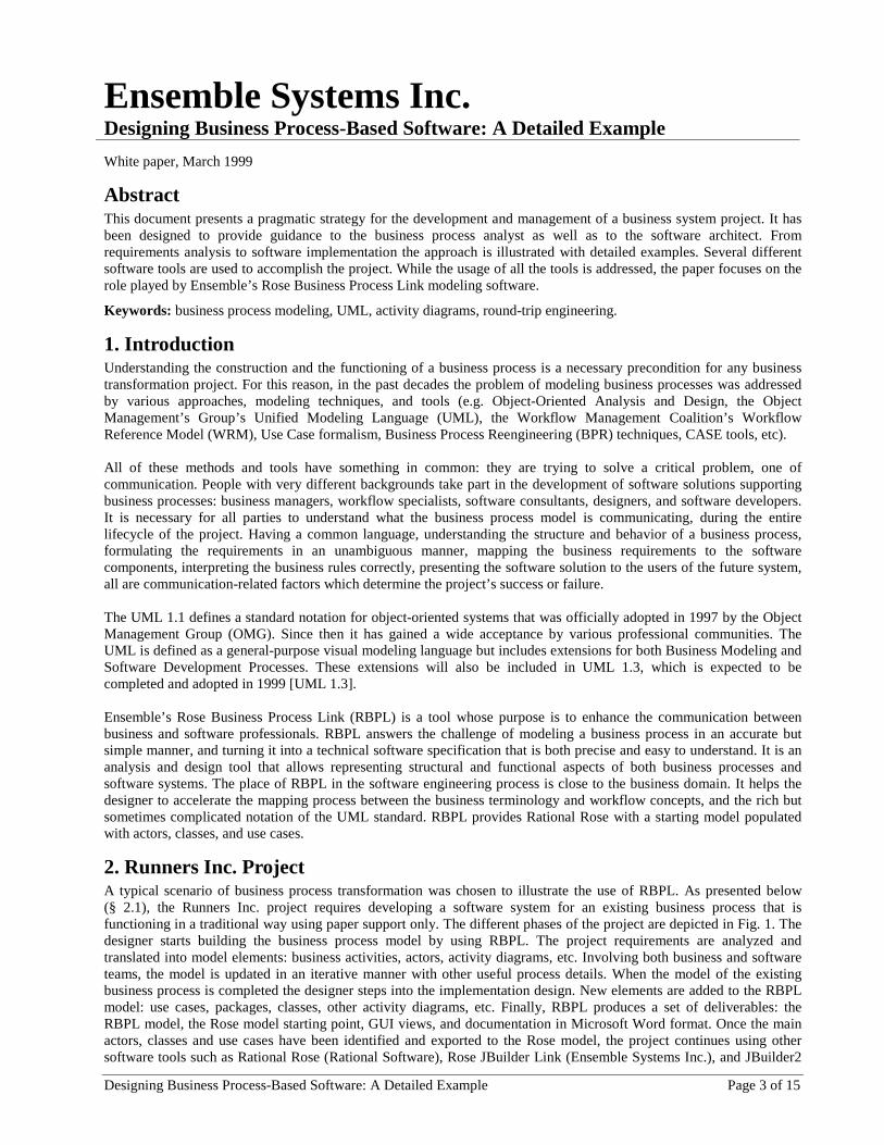
2. Runners Inc. ProjectA typical scenario of business process transformation was chosen to illustrate the use of RBPL. As presented below(§ 2.1), the Runners Inc. project requires developing a software system for an existing business process that isfunctioning in a traditional way using paper support only. The different phases of the project are depicted in Fig. 1. Thedesigner starts building the business process model by using RBPL. The project requirements are analyzed andtranslated into model elements: business activities, actors, activity diagrams, etc. Involving both business and softwareteams, the model is updated in an iterative manner with other useful process details. When the model of the existingbusiness process is completed the designer steps into the implementation design. New elements are added to the RBPLmodel: use cases, packages, classes, other activity diagrams, etc. Finally, RBPL produces a set of deliverables: theRBPL model, the Rose model starting point, GUI views, and documentation in Microsoft Word format. Once the mainactors, classes and use cases have been identified and exported to the Rose model, the project continues using othersoftware tools such as Rational Rose (Rational Software), Rose JBuilder Link (Ensemble Systems Inc.), and JBuilder2
Ensemble Systems Inc. www.ensemble-systems.com
Designing Business Process-Based Software: A Detailed Example Page 4 of 15
(Borland), iteratively via round-trip engineering (RTE). The deliverables of these activities are the Rose model anddocumentation, the JBuilder project, and the Java classes. MS Access (Microsoft) is used to create and maintain theRunners Inc. database, and the Java Runtime Environment (Sun) is used to execute the application.
GUI Views
Database
Provide Data
RunnersInc.
RoseBusinessProcess
Link
RationalRose
RoseJBuilder
Link
JBuilder 2 MSAccess
JavaRuntime
Environment
SoftwareSystem
Design andDevelopment
Business ProcessAnalysis and
Design
BusinessProcessDetails
Project
Requirements
RBPL
Documentation
Rose
DocumentationUpdateModel
JavaClasses
GenerateCode
JBuilderProject
RoseModel
RBPLModel
CodeDevelopment
CreateDatabase
RunApplication
Figure 1. “ Runners Inc. Project” activity diagram
2.1 Runners Inc. RequirementsAs it is often the case, the requirements are presented in plain text. They are the following:
Context: Runners Inc. is a distributor of shoes for jogging enthusiasts. Orders are received by telephone,and they are shipped by mail. They carry two styles of shoe, “ Trotter” and “ Sprinter” . Each shoe isavailable in Men’s sizes 6 through 12, and Ladies’ 6 through 12. They normally carry sufficient inventory tofill all orders. They currently handle all orders on paper, but have now grown large enough that somedegree of automation is required.
Objective: Through a short brainstorming session, it is determined that the most important problem toaddress is that orders are being delayed or lost due to misplaced paperwork. Therefore, support is requiredfor order entry and for shipping, with checks to ensure that all orders are filled in a timely fashion. Otherareas, such as support for inventory management, integration with the accounting system, etc., can beaddressed at a later date.
Constraints: The system should use data storage techniques that support scalability and are easily extendedand maintained. However, short-term volumes are expected to remain relatively low (10 orders per day).
3. Rose Business Process LinkBusiness processes are complex. The modeling task consists of capturing the useful information about the businessprocess. As the business process is often rich and sophisticated, one might expect the model to be quite complex. Thetask of RBPL is to make this complexity manageable. For this purpose, RBPL uses four main categories of elements tomodel a business process: a glossary, feature views, user interface views, and activity diagrams. The usage and theadvantages of these model elements are described below.
Because of the complexity of the business processes, it is almost impossible to capture their entire behavior in a singlediagram. To overcome this problem, in the UML there are five distinct types of diagrams defined: use case diagrams,activity diagrams, statechart diagrams, sequence diagrams, and collaboration diagrams. Use case diagrams are mainlyused to model the context of the system and the software requirements. Activity diagrams are used for workflow andoperation modeling [Booch 98].
Use cases, as defined by the UML standard, are system-oriented. They focus on interactions between humans andsoftware systems, or between sub-systems, as opposite to interactions between humans, or humans and organizations,which is often the case in business processes [Hurlbut 98]. Business processes are also characterized by flows of goal-oriented business activities. They are activity-based processes, i.e. processes in which the activities have deliverables orother business objects as post-conditions [Berkem 98], [Hruby 97].
Ensemble Systems Inc. www.ensemble-systems.com
Designing Business Process-Based Software: A Detailed Example Page 5 of 15
RBPL emphasizes the use of activity diagrams for business process modeling, and suggests the use of use cases onlywhere a software system is involved. However, activity diagrams will be also used to describe the software systembehavior. If one finds it useful to make a distinction between business activities and actions, and software activities andactions, the first may be stereotyped with the stereotypes «business» and «business action» respectively.
The standard UML activity diagram notation includes: initial and final states, activity states, object flow states, branchand merge, fork and join, input and output events, transitions and object flows, and swimlanes [Booch 98],[Rumbaugh 98]. Besides these, RBPL allows one to represent other UML icons on an activity diagram: actors, classes,packages, use cases, dependencies, and views of GUI designs (see the Appendix).
RBPL adds an extension to the UML standard called feature, represented as a triangle. A feature is meant to represent asingle, task-related capability of a system (a requirement whose context is not specified yet). The context in which thefeature is used depends on its association with an activity diagram or use case [RBPL 99].
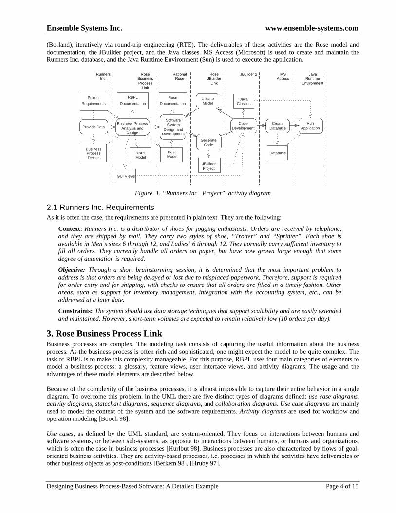
3.1 “Project Requirements” Activity DiagramDuring the requirements analysis, the model of the business process starts being built incrementally. At this stage,different entities of the business process are identified and defined. The requirements of the Runners Inc. project (§ 2.1)are represented using a business-oriented activity diagram in Fig. 2. In a workflow in which a number of differentpeople, functional areas, and subsystems are involved, it is sometimes difficult to keep track of who is responsible forwhat. In order to organize the responsibilities inside Runners Inc., a first step may be to partition the activity graph infour main categories of model elements using swimlanes: actors, “ business” activities, “ software” activities, andbusiness objects.
<< business >>Customer
<< worker >>Sales Rep
<< worker >>Clerk
<< business >>ShippingCompany
�
<< ressource >>Inventory System
<< ressource >>Accounting System
<< business >>
Jogging Shoes
<< business >>Order
<< business >>
Invoice
ProcessOrder
<< business >>
Customer
<< business >>
Ship Order
<< business >>Handle Customer
Request
Runners
BusinessActivities
Business
Actors
Runners
Workers
Runners
Resources
Runners
Business
Objects
Runners
Software
System
PlaceOrder
<<use case>>
<<use case>>
Figure 2. “ Business Requirements” activity diagram
Three types of actors are then identified and represented as swimlanes too: “Business Actors” , “Runners Workers” , and“Runners Resources” . The second step is to define the actors:
Business Actors:- Customer – a person who orders products from Runners Inc.- Shipping Company – DHL, FedEx, UPS, and so on.
Runners Workers:- Clerk – an employee of Runners Inc. who retrieves new orders, packages, labels, and ships the products.- Sales Rep – an employee of Runners Inc. who processes customer requests.
Ensemble Systems Inc. www.ensemble-systems.com
Designing Business Process-Based Software: A Detailed Example Page 6 of 15
Runners Resources:- Accounting System – software that keeps the accounts (not addressed yet).- Inventory System – software that keeps the inventory (not addressed yet).
There are two main business activities that appear clearly from the requirements: one is “Handle Customer Request”during which orders are received by phone, and the other is to “Ship Order” during which orders and products areshipped by mail. The goal of the project is to support these two business activities using a software system. This isrepresented in the diagram using two use case packages: “Place Order” and “Process Order. Four business objects arealso defined: “Customer” , “Order” , “ Invoice” , “Jogging Shoes” .
During requirements analysis it is very important to use a terminology accepted by all the project teams. RBPL providesa Glossary where technical terms from both business and software domains may be defined. These entries are calledGlossary Items and they can be structured in Glossary Packages as follows:
Acronyms:- c.i.f – abbreviation for: cost, insurance & freight (includes insurance and shipping).
Business Terms:- cold call – to telephone a prospect without previous contact.
Software Terms:- JDBC-ODBC – a bridge that provides access via ODBC drivers to databases from Java programs.
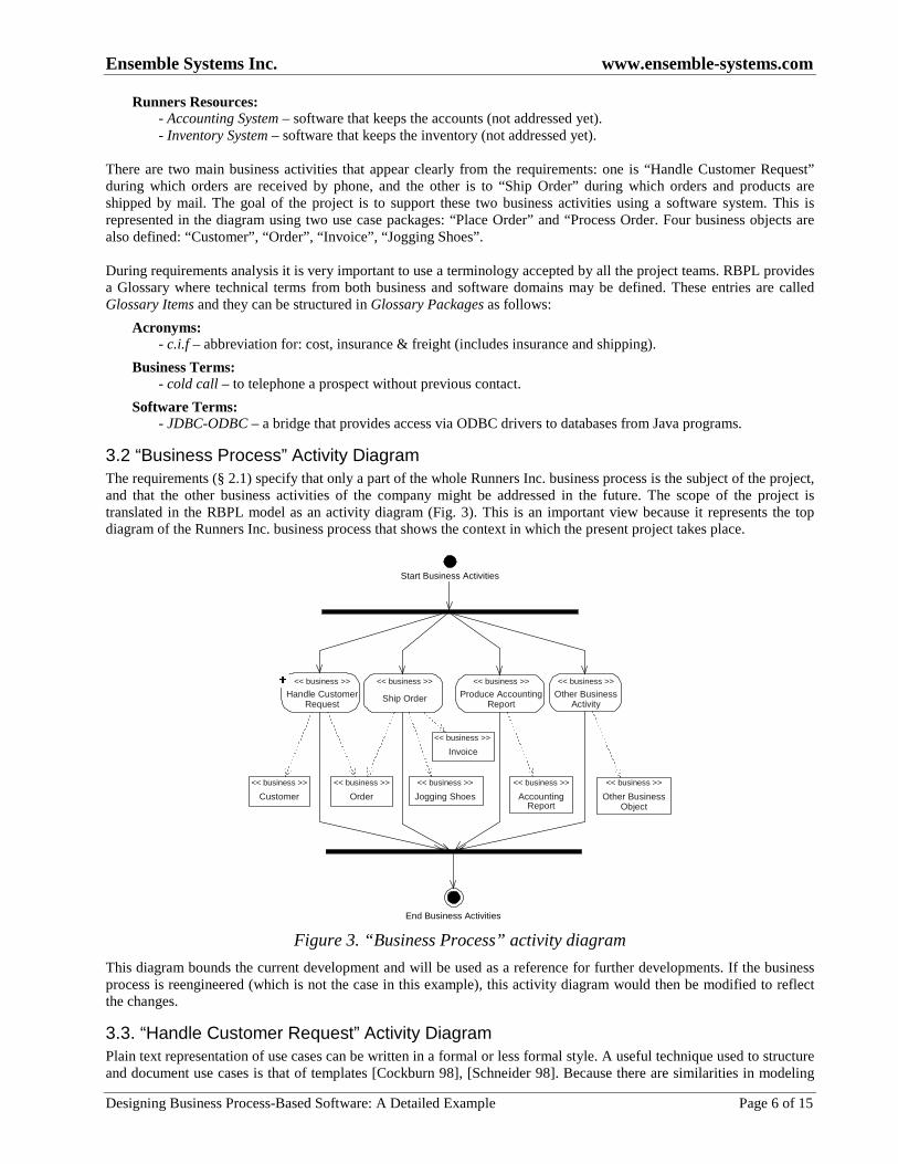
3.2 “Business Process” Activity DiagramThe requirements (§ 2.1) specify that only a part of the whole Runners Inc. business process is the subject of the project,and that the other business activities of the company might be addressed in the future. The scope of the project istranslated in the RBPL model as an activity diagram (Fig. 3). This is an important view because it represents the topdiagram of the Runners Inc. business process that shows the context in which the present project takes place.
Start Business Activities
End Business Activities
�
Handle CustomerRequest
Ship Order Produce AccountingReport
Other BusinessActivity
<< business >>
Invoice
<< business >> << business >> << business >> << business >>
<< business >>
Other BusinessObject
<< business >>
AccountingReport
<< business >>
Jogging Shoes
<< business >>
Order
<< business >>
Customer
Figure 3. “ Business Process” activity diagram
This diagram bounds the current development and will be used as a reference for further developments. If the businessprocess is reengineered (which is not the case in this example), this activity diagram would then be modified to reflectthe changes.
3.3. “Handle Customer Request” Activity DiagramPlain text representation of use cases can be written in a formal or less formal style. A useful technique used to structureand document use cases is that of templates [Cockburn 98], [Schneider 98]. Because there are similarities in modeling
Ensemble Systems Inc. www.ensemble-systems.com
Designing Business Process-Based Software: A Detailed Example Page 7 of 15
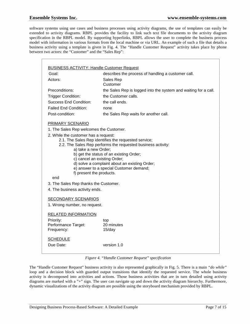
software systems using use cases and business processes using activity diagrams, the use of templates can easily beextended to activity diagrams. RBPL provides the facility to link such text file documents to the activity diagramspecification in the RBPL model. By supporting hyperlinks, RBPL allows the user to complete the business processmodel with information in various formats from the local machine or via URL. An example of such a file that details abusiness activity using a template is given in Fig. 4. The “Handle Customer Request” activity takes place by phonebetween two actors: the “Customer” and the “Sales Rep” :
BUSINESS ACTIVITY: Handle Customer Request
Goal: describes the process of handling a customer call.
Actors: Sales Rep Customer
Preconditions: the Sales Rep is logged into the system and waiting for a call.
Trigger Condition: the Customer calls.
Success End Condition: the call ends.
Failed End Condition: none
Post-condition: the Sales Rep waits for another call.
PRIMARY SCENARIO
1. The Sales Rep welcomes the Customer.
2. While the customer has a request: 2.1. The Sales Rep identifies the requested service; 2.2. The Sales Rep performs the requested business activity:
a) take a new Order;b) get the status of an existing Order;c) cancel an existing Order;d) solve a complaint about an existing Order;e) answer to a special Customer demand;f) present the products.
end
3. The Sales Rep thanks the Customer.
4. The business activity ends.
SECONDARY SCENARIOS
1. Wrong number, no request.
RELATED INFORMATIONPriority: topPerformance Target: 20 minutesFrequency: 15/day
SCHEDULE
Due Date: version 1.0
Figure 4. “ Handle Customer Request” specification
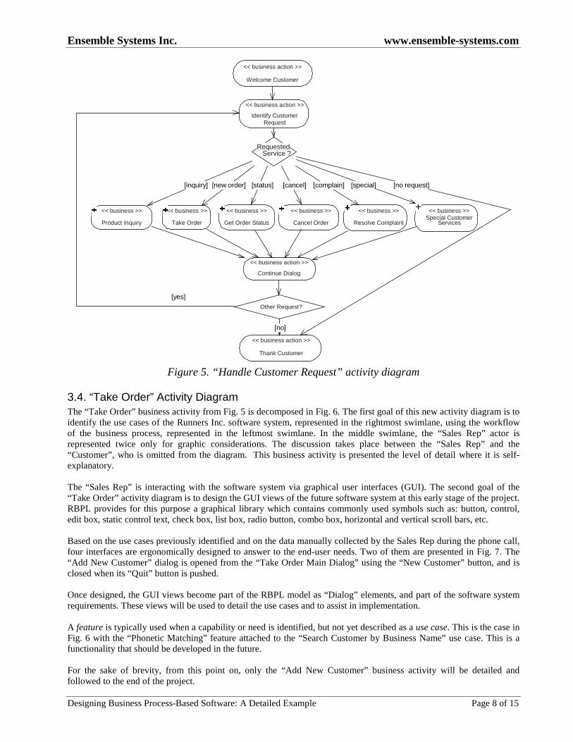
The “Handle Customer Request” business activity is also represented graphically in Fig. 5. There is a main “ do while”loop and a decision block with guarded output transitions that identify the requested service. The whole businessactivity is decomposed into activities and actions. Those business activities that are in turn detailed using activitydiagrams are marked with a ”+” sign. The user can navigate up and down the activity diagram hierarchy. Furthermore,dynamic visualizations of the activity diagram are possible using the storyboard mechanism provided by RBPL.
Ensemble Systems Inc. www.ensemble-systems.com
Designing Business Process-Based Software: A Detailed Example Page 8 of 15
RequestedService ?
Other Request?
[yes]
[no]
[new order] [cancel][status] [complain] [special][inquiry] [no request]
�<< business >>
Take Order
�
<< business >>
Get Order Status
�<< business >>
Product Inquiry
�
<< business >>
Cancel Order
�
<< business >>
Resolve Complaint
�
<< business >>Special Customer
Services
<< business action >>
Identify CustomerRequest
<< business action >>
Thank Customer
<< business action >>
Welcome Customer
<< business action >>
Continue Dialog
Figure 5. “ Handle Customer Request” activity diagram
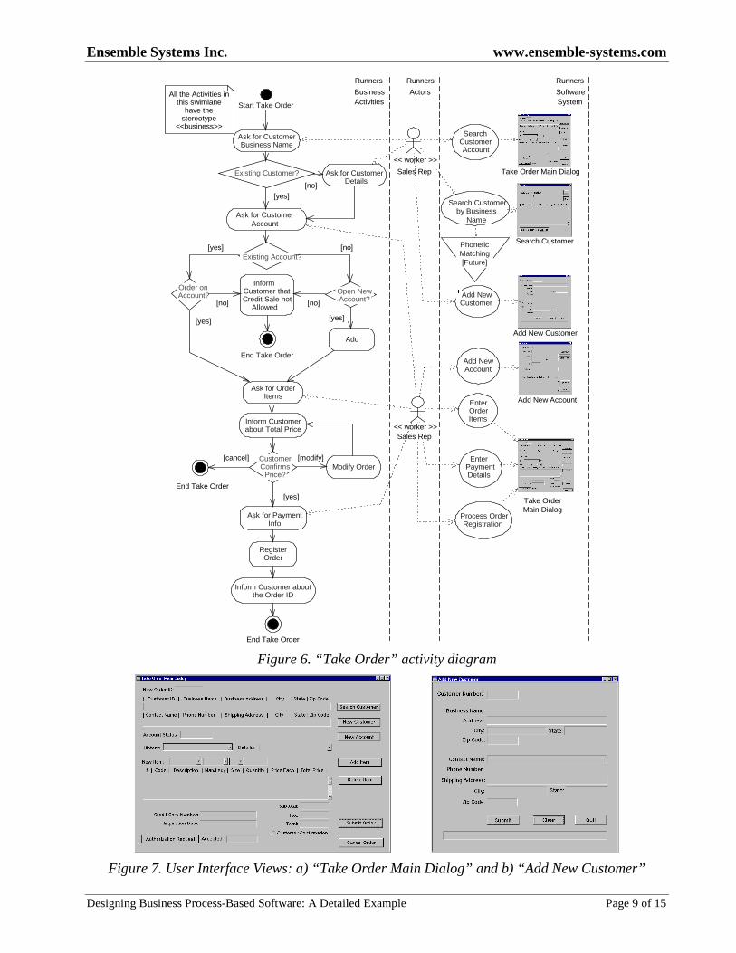
3.4. “Take Order” Activity DiagramThe “Take Order” business activity from Fig. 5 is decomposed in Fig. 6. The first goal of this new activity diagram is toidentify the use cases of the Runners Inc. software system, represented in the rightmost swimlane, using the workflowof the business process, represented in the leftmost swimlane. In the middle swimlane, the “Sales Rep” actor isrepresented twice only for graphic considerations. The discussion takes place between the “Sales Rep” and the“Customer” , who is omitted from the diagram. This business activity is presented the level of detail where it is self-explanatory.
The “Sales Rep” is interacting with the software system via graphical user interfaces (GUI). The second goal of the“Take Order” activity diagram is to design the GUI views of the future software system at this early stage of the project.RBPL provides for this purpose a graphical library which contains commonly used symbols such as: button, control,edit box, static control text, check box, list box, radio button, combo box, horizontal and vertical scroll bars, etc.
Based on the use cases previously identified and on the data manually collected by the Sales Rep during the phone call,four interfaces are ergonomically designed to answer to the end-user needs. Two of them are presented in Fig. 7. The“Add New Customer” dialog is opened from the “Take Order Main Dialog” using the “New Customer” button, and isclosed when its “Quit” button is pushed.
Once designed, the GUI views become part of the RBPL model as “Dialog” elements, and part of the software systemrequirements. These views will be used to detail the use cases and to assist in implementation.
A feature is typically used when a capability or need is identified, but not yet described as a use case. This is the case inFig. 6 with the “Phonetic Matching” feature attached to the “Search Customer by Business Name” use case. This is afunctionality that should be developed in the future.
For the sake of brevity, from this point on, only the “Add New Customer” business activity will be detailed andfollowed to the end of the project.
Ensemble Systems Inc. www.ensemble-systems.com
Designing Business Process-Based Software: A Detailed Example Page 9 of 15
Existing Account?
Open NewAccount?
Order onAccount?
[yes]
[no]
[modify][cancel]
Existing Customer?
[yes]
[no]
[yes]
[no]
[yes]
[no]
[yes]
Sales Rep
Start Take Order
End Take Order
Ask for CustomerBusiness Name
Ask for CustomerDetails
Ask for CustomerAccount
Add NewAccount
SearchCustomerAccount
End Take Order
Ask for PaymentInfo
Add
Modify Order
EnterOrderItems
EnterPaymentDetails
Process OrderRegistration
End Take Order
<< worker >>Sales Rep
Add New Account
Take Order Main Dialog
Take OrderMain Dialog
Runners
BusinessActivities
Runners
Actors
Runners
SoftwareSystem
All the Activities inthis swimlane
have thestereotype
<<business>>
InformCustomer thatCredit Sale not
Allowed
Ask for OrderItems
Inform Customerabout Total Price
CustomerConfirms
Price?
RegisterOrder
Inform Customer aboutthe Order ID
<< worker >>
Search Customerby Business
Name
Search Customer
�
Add NewCustomer
Add New Customer
PhoneticMatching[Future]
Figure 6. “ Take Order” activity diagram
Figure 7. User Interface Views: a) “ Take Order Main Dialog” and b) “ Add New Customer”
Ensemble Systems Inc. www.ensemble-systems.com
Designing Business Process-Based Software: A Detailed Example Page 10 of 15
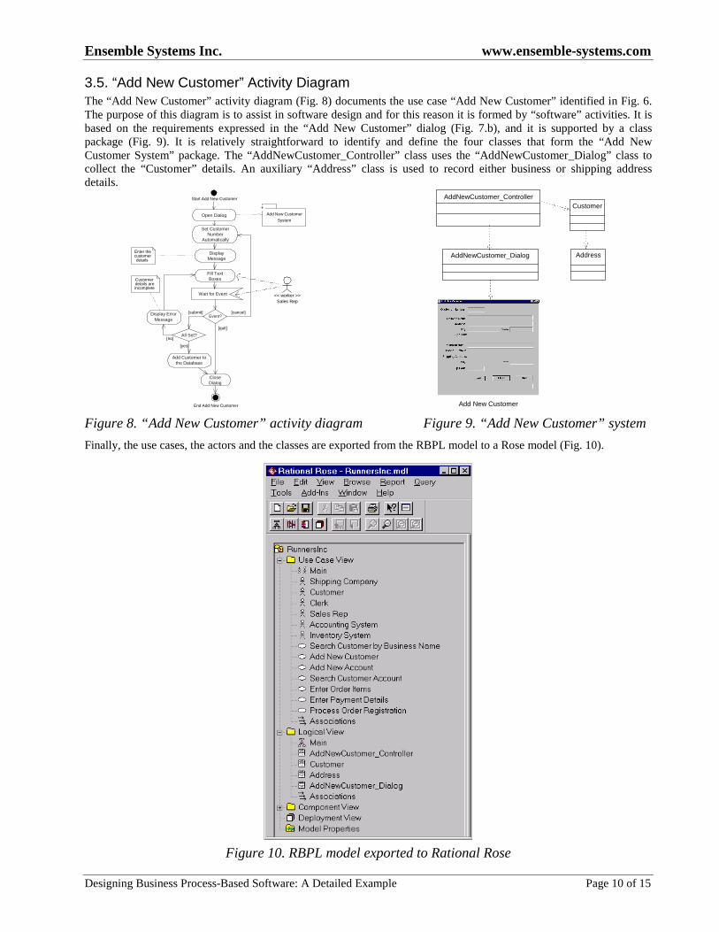
3.5. “Add New Customer” Activity DiagramThe “Add New Customer” activity diagram (Fig. 8) documents the use case “Add New Customer” identified in Fig. 6.The purpose of this diagram is to assist in software design and for this reason it is formed by “software” activities. It isbased on the requirements expressed in the “Add New Customer” dialog (Fig. 7.b), and it is supported by a classpackage (Fig. 9). It is relatively straightforward to identify and define the four classes that form the “Add NewCustomer System” package. The “AddNewCustomer_Controller” class uses the “AddNewCustomer_Dialog” class tocollect the “Customer” details. An auxiliary “Address” class is used to record either business or shipping addressdetails.
Event?
All Set?
[submit] [cancel]
[yes]
[no]
[quit]
Start Add New Customer
End Add New Customer
Set CustomerNumber
Automatically
DisplayMessage
Wait for Event
Fill TextBoxes
Open Dialog
CloseDialog
Add Customer tothe Database
�
Display ErrorMessage
Customerdetails areincomplete
Enter thecustomerdetails
Add New Customer
System
<< worker >>Sales Rep
Add New Customer
Customer
AddressAddNewCustomer_Dialog
AddNewCustomer_Controller
Figure 8. “ Add New Customer” activity diagram Figure 9. “ Add New Customer” system
Finally, the use cases, the actors and the classes are exported from the RBPL model to a Rose model (Fig. 10).
Figure 10. RBPL model exported to Rational Rose
Ensemble Systems Inc. www.ensemble-systems.com
Designing Business Process-Based Software: A Detailed Example Page 11 of 15
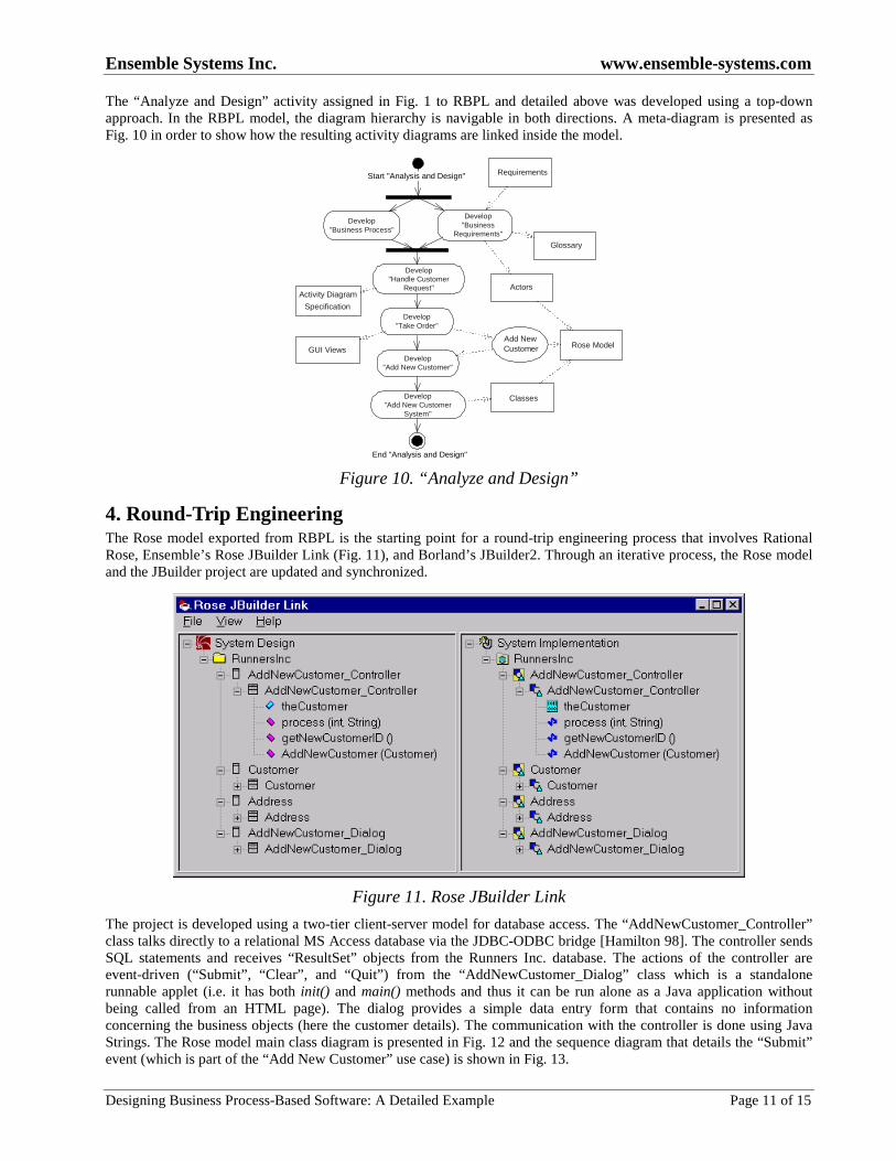
The “Analyze and Design” activity assigned in Fig. 1 to RBPL and detailed above was developed using a top-downapproach. In the RBPL model, the diagram hierarchy is navigable in both directions. A meta-diagram is presented asFig. 10 in order to show how the resulting activity diagrams are linked inside the model.
Actors
Requirements
Develop"Business
Requirements"
Develop"Business Process"
Develop"Handle Customer
Request"
Develop"Take Order"
Add NewCustomer
Develop"Add New Customer"
Start "Analysis and Design"
End "Analysis and Design"
Glossary
Activity Diagram
Specification
GUI ViewsRose Model
Develop"Add New Customer
System"
Classes
Figure 10. “ Analyze and Design”
4. Round-Trip EngineeringThe Rose model exported from RBPL is the starting point for a round-trip engineering process that involves RationalRose, Ensemble’s Rose JBuilder Link (Fig. 11), and Borland’s JBuilder2. Through an iterative process, the Rose modeland the JBuilder project are updated and synchronized.
Figure 11. Rose JBuilder Link
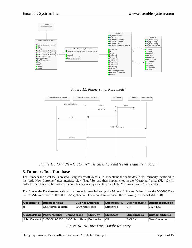
The project is developed using a two-tier client-server model for database access. The “AddNewCustomer_Controller”class talks directly to a relational MS Access database via the JDBC-ODBC bridge [Hamilton 98]. The controller sendsSQL statements and receives “ResultSet” objects from the Runners Inc. database. The actions of the controller areevent-driven (“Submit” , “Clear” , and “Quit” ) from the “AddNewCustomer_Dialog” class which is a standalonerunnable applet (i.e. it has both init() and main() methods and thus it can be run alone as a Java application withoutbeing called from an HTML page). The dialog provides a simple data entry form that contains no informationconcerning the business objects (here the customer details). The communication with the controller is done using JavaStrings. The Rose model main class diagram is presented in Fig. 12 and the sequence diagram that details the “Submit”event (which is part of the “Add New Customer” use case) is shown in Fig. 13.
Ensemble Systems Inc. www.ensemble-systems.com
Designing Business Process-Based Software: A Detailed Example Page 12 of 15
AddNewCustomer_Dialog
AddNewCustomer_Dialog()init()jbInit()button1_actionPerformed()button2_actionPerformed()button3_actionPerformed()initFieldControls()getAppletInfo()getParameterInfo()start()stop()destroy()main()
AddNewCustomer_Controller
theCustomer : Customer = new Customer()
process()getNewCustomerID()AddNewCustomer()
11 11
Address
m_street : Stringm_city : Stringm_state : Stringm_zipCode : String
Address()Address()getStreet()getCi ty()getState()getZipCode()setStreet()setCity()setState()setZipCode()isValid()
Customer
m_name : Stringm_id : Stringm_address : Addressm_contact : Stringm_phone : Stringm_shippingAddress : Address
Customer()setId()getId()setName()getName()setAddress()getAddress()setContact()getContact()setPhone()getPhone()setShippingAddress()getShippingAddress()isValid()
11 11
11 11
11 11
Applet(from Unresolved References)
Figure 12. Runners Inc. Rose model
: AddNewCustomer_Dialog : AddNewCustomer_Controller : Customer : Address : MSAccessDB
process(int, String)<<set>> <<set>>
isValid( )
AddNewCustomer()
<<no>>
<<yes>>
Figure 13. “ Add New Customer” use case: “ Submit” event sequence diagram
5. Runners Inc. DatabaseThe Runners Inc database is created using Microsoft Access 97. It contains the same data fields formerly identified inthe “Add New Customer” user interface view (Fig. 7.b), and then implemented in the “Customer” class (Fig. 12). Inorder to keep track of the customer record history, a supplementary data field, “CustomerStatus” , was added.
The RunnersIncDatabase.mdb should be properly installed using the Microsoft Access Driver from the "ODBC DataSource Administrator" of the ODBC32 application. For more details consult the following reference [Milne 98].
CustomerId BusinessName BusinessAddress BusinessCity BusinessState BusinessZipCode8 Early Birds Joggers 8900 Nest Plaza Ducksville OR 7W7 1X1
ContactName PhoneNumber ShipAddress ShipCity ShipState ShipZipCode CustomerStatus
John Carefoot 1-800-345-6754 8900 Nest Plaza Ducksville OR 7W7 1X1 New Customer
Figure 14. “ Runners Inc. Database” entry
Ensemble Systems Inc. www.ensemble-systems.com
Designing Business Process-Based Software: A Detailed Example Page 13 of 15
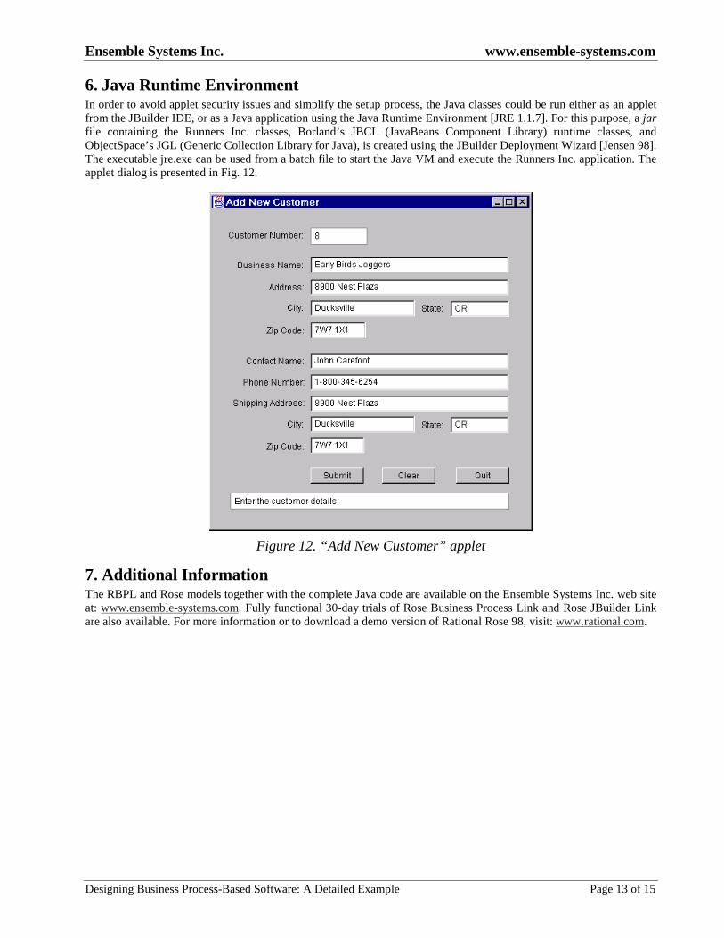
6. Java Runtime EnvironmentIn order to avoid applet security issues and simplify the setup process, the Java classes could be run either as an appletfrom the JBuilder IDE, or as a Java application using the Java Runtime Environment [JRE 1.1.7]. For this purpose, a jarfile containing the Runners Inc. classes, Borland’s JBCL (JavaBeans Component Library) runtime classes, andObjectSpace’s JGL (Generic Collection Library for Java), is created using the JBuilder Deployment Wizard [Jensen 98].The executable jre.exe can be used from a batch file to start the Java VM and execute the Runners Inc. application. Theapplet dialog is presented in Fig. 12.
Figure 12. “ Add New Customer” applet
7. Additional InformationThe RBPL and Rose models together with the complete Java code are available on the Ensemble Systems Inc. web siteat: www.ensemble-systems.com. Fully functional 30-day trials of Rose Business Process Link and Rose JBuilder Linkare also available. For more information or to download a demo version of Rational Rose 98, visit: www.rational.com.
Ensemble Systems Inc. www.ensemble-systems.com
Designing Business Process-Based Software: A Detailed Example Page 14 of 15
8. Bibliography
[Berkem 98] Berkem, B., “Formalizing a ‘bridge’ from the UML’s Activity Diagram toward Use Cases” ,OOPSLA’98 Workshop on Formalizing UML, Vancouver, Canada, 1998,http://www.oblog.pt/workshop_program.htm
[Booch 98] Booch, G., Jacobson, I., Rumbaugh, J., “ The Unified Modeling Language User Guide” , Addison-Wesley Pub Co., 1998, ISBN: 0201571684,http://www.amazon.com/exec/obidos/ASIN/0201571684/argoumlhomepage/002-5829840-5207043
[Cockburn 98] Cockburn, A., “ Basic Use Case Template” , 1998, http://members.aol.com/acockburn/papers/uctempla.htm
[Hamilton 98] Hamilton, G., Cattell, R., Fisher, M., “ JDBC Database Access with Java. A Tutorial andAnnotated Reference” , Addison-Wesley Pub Co., 1998, ISBN: 0201309955,http://www.amazon.com/exec/obidos/ASIN/0201309955/o/qid=922561735/sr=2-2/002-5829840-5207043
[Hruby 97] Hruby, P., “ The Object Model for a Product Based Development Process” , ECOOP ’97 Workshop on
Modeling Software Processes and Artifacts, Jyväskylä, Finland, 1997,http://www.navision.com/services/methodology/methodologists_site.asp
[Hurlbut 98] Hurlbut, R.R, “ Managing Domain Architecture Evolution Through Adaptive Use Case and BusinessRule Models” , Ph.D. Thesis, Illinois Institute of Technology, 1998, http://www.iit.edu/~rhurlbut/research.html
[Jensen 98] Jensen, C., Stone, B., Anderson, L., “ JBuilder Essentials” , Osborne McGraw-Hill; ISBN: 0078822238,1998, http://www.amazon.com/exec/obidos/ASIN/0078822238/qid%3D922583109/002-5829840-5207043
[JRE 1.1.7] Java Runtime Environment, JRE 1.1.7B, http://java.sun.com/products/jdk/1.1/jre/download-jre-windows.html
[Milne 98] Milne, P., Andrews, M., “The Jtable Class Is DB-Aware” , The Swing Connection, 1998,http://java.sun.com/products/jfc/tsc/archive/tech_topics_arch/db/db.html
[RBPL 99] Ensemble Suite, Technical documentation, http://www.ensemble-systems.com/downloads.html
[Rumbaugh 98] Rumbaugh, J., Jacobson, I., Booch, G., “ The Unified Modeling Language Reference Manual” ,Addison-Wesley Pub Co., 1998, ISBN: 020130998X,http://www.amazon.com/exec/obidos/ASIN/020130998X/ref=sim_books/002-5829840-5207043
[Schneider 98] Schneider, G., Winters, J. P., Jacobson, I., “ Applying Use Cases: A Practical Guide” , Addison-Wesley Pub Co., 1998, ISBN: 0201309815,http://www.amazon.com/exec/obidos/ASIN/0201309815/ref=sim_books/002-5829840-5207043
[UML 1.3] OMG UML V1.3 alpha R2, January 1999, http://www.rational.com/uml/index.jtmpl
Ensemble Systems Inc. www.ensemble-systems.com
Designing Business Process-Based Software: A Detailed Example Page 15 of 15
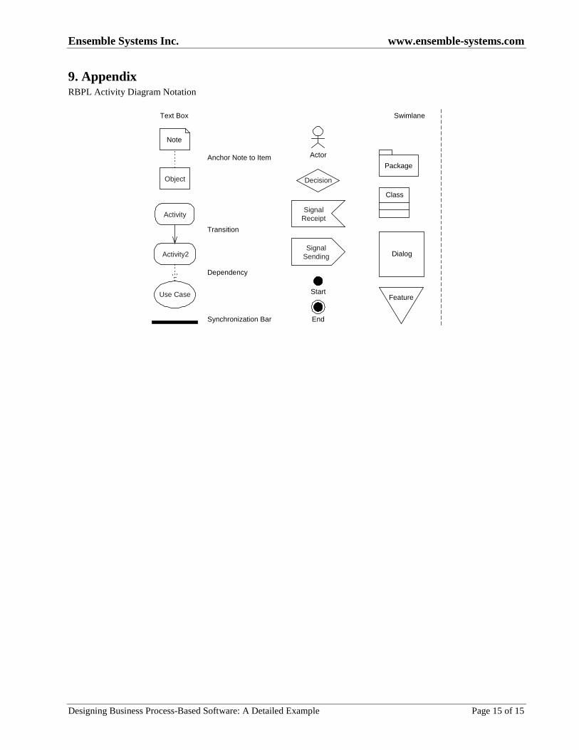
9. AppendixRBPL Activity Diagram Notation
Swimlane
Package
Class
Dialog
Feature
Decision
Actor
SignalSending
SignalReceipt
End
Start
Text Box
Note
Object
Activity2
Activity
Use Case
Anchor Note to Item
Dependency
Transition
Synchronization Bar