Embed Size (px)
Citation preview
1
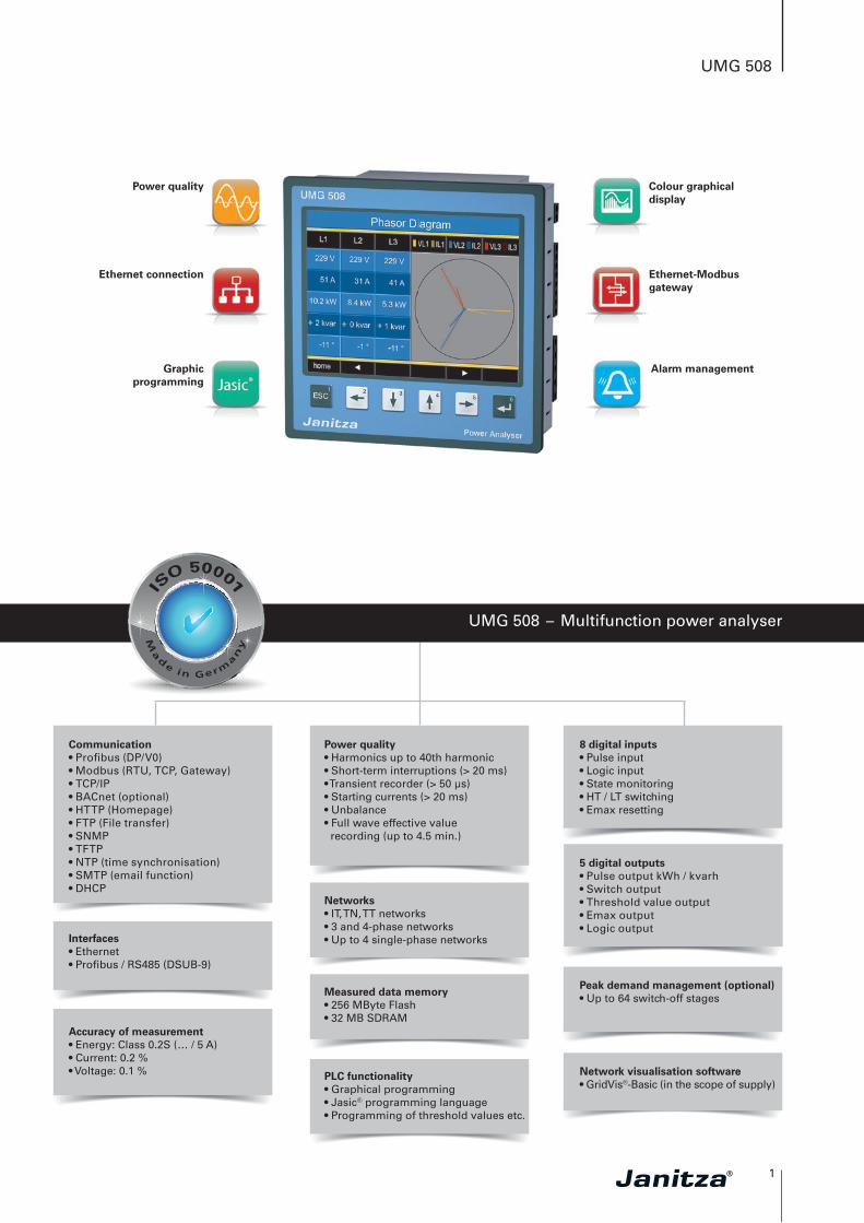
UMG 508
UMG 508 – Multifunction power analyser
Alarm management
Colour graphical display
Power quality
Graphicprogramming
Ethernet connection
5 digital outputs• Pulse output kWh / kvarh• Switch output• Threshold value output• Emax output• Logic output
8 digital inputs• Pulse input• Logic input• State monitoring• HT / LT switching• Emax resetting
Peak demand management (optional)• Up to 64 switch-off stages
Network visualisation software• GridVis®-Basic (in the scope of supply)
Interfaces• Ethernet• Profi bus / RS485 (DSUB-9)
Communication• Profi bus (DP/V0)• Modbus (RTU, TCP, Gateway)• TCP/IP• BACnet (optional)• HTTP (Homepage)• FTP (File transfer)• SNMP• TFTP• NTP (time synchronisation)• SMTP (email function)• DHCP
Accuracy of measurement• Energy: Class 0.2S (… / 5 A)• Current: 0.2 %• Voltage: 0.1 %
Networks• IT, TN, TT networks• 3 and 4-phase networks• Up to 4 single-phase networks
Measured data memory• 256 MByte Flash• 32 MB SDRAM
Power quality • Harmonics up to 40th harmonic• Short-term interruptions (> 20 ms)• Transient recorder (> 50 μs)• Starting currents (> 20 ms)• Unbalance• Full wave effective value recording (up to 4.5 min.)
PLC functionality• Graphical programming• Jasic® programming language• Programming of threshold values etc.
Ethernet-Modbus gateway
2
UMG 508
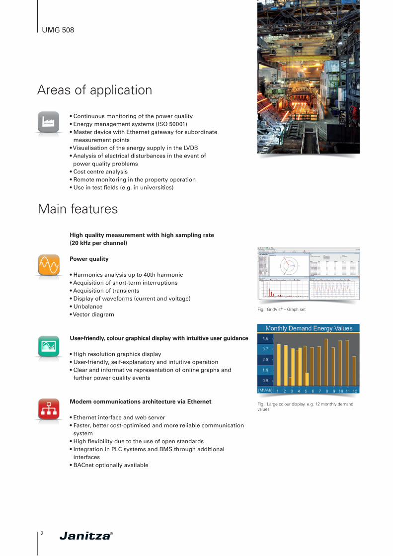
• Continuous monitoring of the power quality• Energy management systems (ISO 50001)• Master device with Ethernet gateway for subordinate
measurement points• Visualisation of the energy supply in the LVDB• Analysis of electrical disturbances in the event of
power quality problems• Cost centre analysis• Remote monitoring in the property operation• Use in test fi elds (e.g. in universities)
Areas of application
Main features
High quality measurement with high sampling rate (20 kHz per channel)
Power quality
• Harmonics analysis up to 40th harmonic• Acquisition of short-term interruptions• Acquisition of transients• Display of waveforms (current and voltage)• Unbalance• Vector diagram
User-friendly, colour graphical display with intuitive user guidance
• High resolution graphics display• User-friendly, self-explanatory and intuitive operation• Clear and informative representation of online graphs and
further power quality events
Modern communications architecture via Ethernet
• Ethernet interface and web server• Faster, better cost-optimised and more reliable communication
system• High fl exibility due to the use of open standards• Integration in PLC systems and BMS through additional
interfaces• BACnet optionally available
Fig.: GridVis® – Graph set
Fig.: Large colour display, e.g. 12 monthly demand values
3
UMG 508
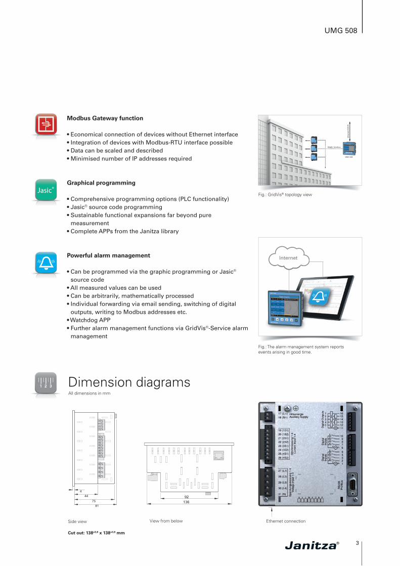
Modbus Gateway function
• Economical connection of devices without Ethernet interface• Integration of devices with Modbus-RTU interface possible • Data can be scaled and described• Minimised number of IP addresses required
Graphical programming
• Comprehensive programming options (PLC functionality)• Jasic® source code programming• Sustainable functional expansions far beyond pure
measurement• Complete APPs from the Janitza library
Powerful alarm management
• Can be programmed via the graphic programming or Jasic® source code
• All measured values can be used • Can be arbitrarily, mathematically processed • Individual forwarding via email sending, switching of digital
outputs, writing to Modbus addresses etc.• Watchdog APP• Further alarm management functions via GridVis®-Service alarm
management
Side view View from below Ethernet connection
Dimension diagramsAll dimensions in mm
Fig.: GridVis® topology view
Fig.: The alarm management system reportsevents arising in good time.
InternetInternet
Cut out: 138+0,8 x 138+0,8 mm
4
UMG 508
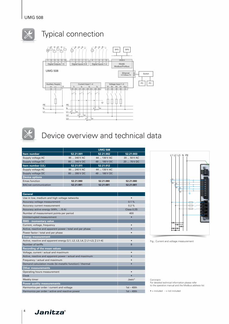
Typical connection
Device overview and technical data
Digital Outputs 1-5 Digital Inputs 5-8 RS485Modbus/Profibus
Digital Inputs 1-4
DSUB-911 12 13 14 15 16 1 2 3 4 5 6 7 8 9 105 4 3 2 1 8 7 6 5 4 3 2 1
UMG 508Ethernet
10/100Base-TX RJ4
5
Auxiliary SupplyN/- L/+
18 17
PE
Current Input 1-4I1
19 20 21 22 23 24 25 26
I2 I3 I427 28 29 30
Voltage Input 1-4V1 V2 V3 V4 Vref
31
L1
N
PE
L1
L2
L3
N
PE
S1 S2
S1 S2
S1 S2
S1 S2
SPS SPS
Switch
PC PC
S1
S2 S1
S2 S1
S2
L1 N PEL3L2
Fig.: Current and voltage measurement
UMG 508
Item number 52.21.001 52.21.002 52.21.003Supply voltage AC 95 ... 240 V AC 44 ... 130 V AC 20 ... 50 V AC
Supply voltage DC 80 … 340 V DC 48 … 180 V DC 20 … 70 V DC
Item number (UL) 52.21.011 52.21.012Supply voltage AC 95 ... 240 V AC 44 ... 130 V AC
Supply voltage DC 80 … 280 V DC 48 … 180 V DC
Device optionsEmax function 52.21.080 52.21.080 52.21.080
BACnet communication 52.21.081 52.21.081 52.21.081
GeneralUse in low, medium and high voltage networks •
Accuracy voltage measurement 0.1 %
Accuracy current measurement 0.2 %
Accuracy active energy (kWh, …/5 A) Class 0.2S
Number of measurement points per period 400
Uninterrupted measurement •
RMS - momentary valueCurrent, voltage, frequency •
Active, reactive and apparent power / total and per phase •
Power factor / total and per phase •
Energy measurementActive, reactive and apparent energy [L1, L2, L3, L4, ∑ L1–L3, ∑ L1–4] •
Number of tariffs 8
Recording of the mean valuesVoltage, current / actual and maximum •
Active, reactive and apparent power / actual and maximum •
Frequency / actual and maximum •
Demand calculation mode (bi-metallic function) / thermal •
Other measurementsOperating hours measurement •
Clock •
Weekly timer Jasic®
Power quality measurementsHarmonics per order / current and voltage 1st – 40th
Harmonics per order / active and reactive power 1st – 40th
Comment: For detailed technical information please refer to the operation manual and the Modbus address list
• = included - = not included
5
UMG 508
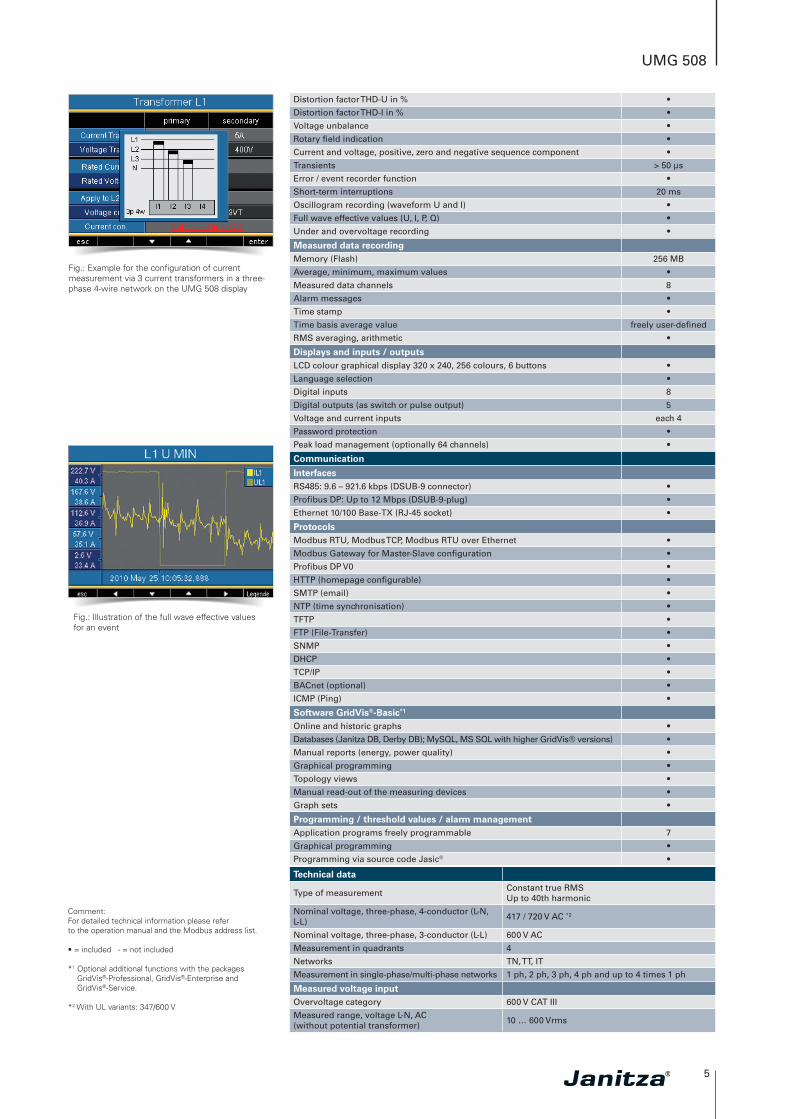
Fig.: Illustration of the full wave effective values for an event
Fig.: Example for the configuration of current measurement via 3 current transformers in a three-phase 4-wire network on the UMG 508 display
Distortion factor THD-U in % •
Distortion factor THD-I in % •
Voltage unbalance •
Rotary field indication •
Current and voltage, positive, zero and negative sequence component •
Transients > 50 µs
Error / event recorder function •
Short-term interruptions 20 ms
Oscillogram recording (waveform U and I) •
Full wave effective values (U, I, P, Q) •
Under and overvoltage recording •
Measured data recordingMemory (Flash) 256 MB
Average, minimum, maximum values •
Measured data channels 8
Alarm messages •
Time stamp •
Time basis average value freely user-defined
RMS averaging, arithmetic •
Displays and inputs / outputsLCD colour graphical display 320 x 240, 256 colours, 6 buttons •
Language selection •
Digital inputs 8
Digital outputs (as switch or pulse output) 5
Voltage and current inputs each 4
Password protection •
Peak load management (optionally 64 channels) •
Communication
InterfacesRS485: 9.6 – 921.6 kbps (DSUB-9 connector) •
Profibus DP: Up to 12 Mbps (DSUB-9-plug) •
Ethernet 10/100 Base-TX (RJ-45 socket) •
ProtocolsModbus RTU, Modbus TCP, Modbus RTU over Ethernet •
Modbus Gateway for Master-Slave configuration •
Profibus DP V0 •
HTTP (homepage configurable) •
SMTP (email) •
NTP (time synchronisation) •
TFTP •
FTP (File-Transfer) •
SNMP •
DHCP •
TCP/IP •
BACnet (optional) •
ICMP (Ping) •
Software GridVis®-Basic*1
Online and historic graphs •
Databases (Janitza DB, Derby DB); MySQL, MS SQL with higher GridVis® versions) •
Manual reports (energy, power quality) •
Graphical programming •
Topology views •
Manual read-out of the measuring devices •
Graph sets •
Programming / threshold values / alarm managementApplication programs freely programmable 7
Graphical programming •
Programming via source code Jasic® •
Technical data
Type of measurementConstant true RMS Up to 40th harmonic
Nominal voltage, three-phase, 4-conductor (L-N, L-L)
417 / 720 V AC *2
Nominal voltage, three-phase, 3-conductor (L-L) 600 V AC
Measurement in quadrants 4
Networks TN, TT, IT
Measurement in single-phase/multi-phase networks 1 ph, 2 ph, 3 ph, 4 ph and up to 4 times 1 ph
Measured voltage inputOvervoltage category 600 V CAT III
Measured range, voltage L-N, AC (without potential transformer)
10 … 600 Vrms
Comment: For detailed technical information please refer to the operation manual and the Modbus address list.
• = included - = not included
*1 Optional additional functions with the packages GridVis®-Professional, GridVis®-Enterprise and GridVis®-Service.
*2 With UL variants: 347/600 V
6
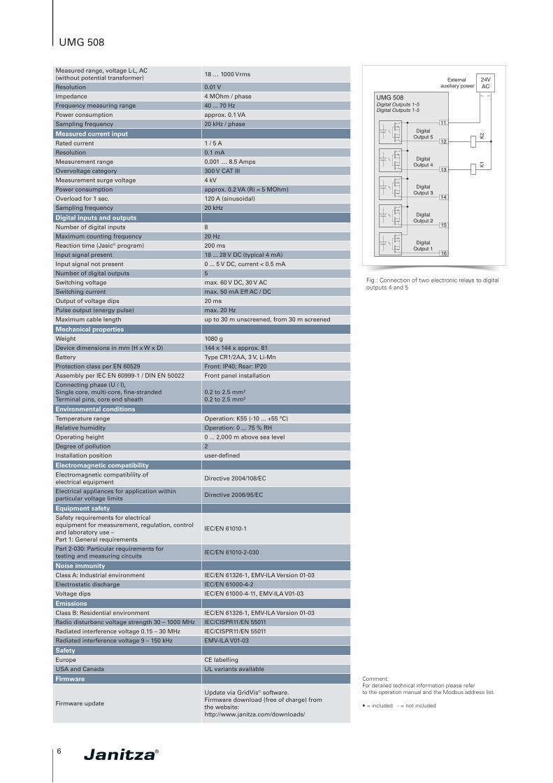
UMG 508
External auxiliary power
Fig.: Connection of two electronic relays to digital outputs 4 and 5
Measured range, voltage L-L, AC (without potential transformer)
18 … 1000 Vrms
Resolution 0.01 V
Impedance 4 MOhm / phase
Frequency measuring range 40 ... 70 Hz
Power consumption approx. 0.1 VA
Sampling frequency 20 kHz / phase
Measured current inputRated current 1 / 5 A
Resolution 0.1 mA
Measurement range 0.001 … 8.5 Amps
Overvoltage category 300 V CAT III
Measurement surge voltage 4 kV
Power consumption approx. 0.2 VA (Ri = 5 MOhm)
Overload for 1 sec. 120 A (sinusoidal)
Sampling frequency 20 kHz
Digital inputs and outputsNumber of digital inputs 8
Maximum counting frequency 20 Hz
Reaction time (Jasic® program) 200 ms
Input signal present 18 ... 28 V DC (typical 4 mA)
Input signal not present 0 ... 5 V DC, current < 0.5 mA
Number of digital outputs 5
Switching voltage max. 60 V DC, 30 V AC
Switching current max. 50 mA Eff AC / DC
Output of voltage dips 20 ms
Pulse output (energy pulse) max. 20 Hz
Maximum cable length up to 30 m unscreened, from 30 m screened
Mechanical propertiesWeight 1080 g
Device dimensions in mm (H x W x D) 144 x 144 x approx. 81
Battery Type CR1/2AA, 3 V, Li-Mn
Protection class per EN 60529 Front: IP40; Rear: IP20
Assembly per IEC EN 60999-1 / DIN EN 50022 Front panel installation
Connecting phase (U / I), Single core, multi-core, fine-stranded Terminal pins, core end sheath
0.2 to 2.5 mm²0.2 to 2.5 mm²
Environmental conditionsTemperature range Operation: K55 (-10 ... +55 °C)
Relative humidity Operation: 0 ... 75 % RH
Operating height 0 ... 2,000 m above sea level
Degree of pollution 2
Installation position user-defined
Electromagnetic compatibilityElectromagnetic compatibility of electrical equipment
Directive 2004/108/EC
Electrical appliances for application within particular voltage limits
Directive 2006/95/EC
Equipment safetySafety requirements for electrical equipment for measurement, regulation, control and laboratory use – Part 1: General requirements
IEC/EN 61010-1
Part 2-030: Particular requirements fortesting and measuring circuits
IEC/EN 61010-2-030
Noise immunityClass A: Industrial environment IEC/EN 61326-1, EMV-ILA Version 01-03
Electrostatic discharge IEC/EN 61000-4-2
Voltage dips IEC/EN 61000-4-11, EMV-ILA V01-03
EmissionsClass B: Residential environment IEC/EN 61326-1, EMV-ILA Version 01-03
Radio disturbanc voltage strength 30 – 1000 MHz IEC/CISPR11/EN 55011
Radiated interference voltage 0.15 – 30 MHz IEC/CISPR11/EN 55011
Radiated interference voltage 9 – 150 kHz EMV-ILA V01-03
SafetyEurope CE labelling
USA and Canada UL variants available
Firmware
Firmware update
Update via GridVis® software.Firmware download (free of charge) from the website:http://www.janitza.com/downloads/
Comment: For detailed technical information please refer to the operation manual and the Modbus address list.
• = included - = not included
Version 01/2015 • Subject to technical alterations.
Sal
es p
artn
er
Janitza electronics GmbHVor dem Polstück 1D-35633 LahnauGermany
Tel.: +49 6441 9642-0Fax: +49 6441 [email protected]
Smart Energy &Power Quality Solutions