Embed Size (px)
Citation preview
April 2012 Doc ID 022713 Rev 1 1/69
UM1510User manual
STM32L152D-EVAL demonstration firmware
IntroductionThis user manual describes the demonstration firmware running on the STM32L152D-EVAL evaluation board, which can be used to evaluate the capabilities of the STM32L152ZD(T6) microcontroller and on-board peripherals.
This demo contains many applications that can be easily reused, such as RTC calendar, file system FAT implementation on SD Card, Wave player with STM32 I2S peripheral, voice recording, automatic measure of the power consumption in several operating modes, Dual Interface EEPROM applications (ESL and DataLogger), temperature sensor interfacing and TFT LCD.
The STM32L152D-EVAL board is delivered with the demonstration programmed in the internal Flash memory, and all the files needed by the demonstration are programmed in the MicroSD card. The demonstration is executed at each reset (board power-up, external reset, etc.).
In case the STM32L152D-EVAL board was not factory-programmed or the demonstration application was erased, the Bootloader, IAP or USB DFU can be used to program this file. For more details, refer to Section 3: STM32L152D-EVAL demonstration package and Section 4: STM32L152D-EVAL demonstration programming.
Note: Before you execute the demonstration, make sure that all EVAL board jumpers are well configured. For more details, refer to Section 1.10.11: STM32L152D-EVAL board jumper configuration.
This demonstration firmware and other such firmware are available for download from the STMicroelectronics website: www.st.com.
www.st.com
Contents UM1510
2/69 Doc ID 022713 Rev 1
Contents
1 Functional description . . . . . . . . . . . . . . . . . . . . . . . . . . . . . . . . . . . . . . . 6
1.1 Power control . . . . . . . . . . . . . . . . . . . . . . . . . . . . . . . . . . . . . . . . . . . . . . . 6
1.2 Clocking . . . . . . . . . . . . . . . . . . . . . . . . . . . . . . . . . . . . . . . . . . . . . . . . . . . 7
1.3 Reset control . . . . . . . . . . . . . . . . . . . . . . . . . . . . . . . . . . . . . . . . . . . . . . . 7
1.4 Debug JTAG interface . . . . . . . . . . . . . . . . . . . . . . . . . . . . . . . . . . . . . . . . 7
1.5 Serial wire debugger interface . . . . . . . . . . . . . . . . . . . . . . . . . . . . . . . . . . 7
1.6 Embedded ST-LINK . . . . . . . . . . . . . . . . . . . . . . . . . . . . . . . . . . . . . . . . . . 7
1.7 Display devices . . . . . . . . . . . . . . . . . . . . . . . . . . . . . . . . . . . . . . . . . . . . . . 7
1.7.1 LCD . . . . . . . . . . . . . . . . . . . . . . . . . . . . . . . . . . . . . . . . . . . . . . . . . . . . . 7
1.7.2 LCD Glass . . . . . . . . . . . . . . . . . . . . . . . . . . . . . . . . . . . . . . . . . . . . . . . . 7
1.7.3 LEDs . . . . . . . . . . . . . . . . . . . . . . . . . . . . . . . . . . . . . . . . . . . . . . . . . . . . 7
1.8 Interfaces . . . . . . . . . . . . . . . . . . . . . . . . . . . . . . . . . . . . . . . . . . . . . . . . . . 8
1.8.1 RS232 . . . . . . . . . . . . . . . . . . . . . . . . . . . . . . . . . . . . . . . . . . . . . . . . . . . 8
1.9 IrDA . . . . . . . . . . . . . . . . . . . . . . . . . . . . . . . . . . . . . . . . . . . . . . . . . . . . . . 8
1.10 Miscellaneous peripherals . . . . . . . . . . . . . . . . . . . . . . . . . . . . . . . . . . . . . 8
1.10.1 Joystick . . . . . . . . . . . . . . . . . . . . . . . . . . . . . . . . . . . . . . . . . . . . . . . . . . 8
1.10.2 Push-buttons . . . . . . . . . . . . . . . . . . . . . . . . . . . . . . . . . . . . . . . . . . . . . . 8
1.10.3 12-bit analog-to-digital converter (ADC) . . . . . . . . . . . . . . . . . . . . . . . . . 8
1.10.4 Audio . . . . . . . . . . . . . . . . . . . . . . . . . . . . . . . . . . . . . . . . . . . . . . . . . . . . 8
1.10.5 MicroSD card . . . . . . . . . . . . . . . . . . . . . . . . . . . . . . . . . . . . . . . . . . . . . . 8
1.10.6 Serial EEPROM . . . . . . . . . . . . . . . . . . . . . . . . . . . . . . . . . . . . . . . . . . . . 8
1.10.7 M24LR64 dual Interface EEPROM (RF/I²C) . . . . . . . . . . . . . . . . . . . . . . 9
1.10.8 SRAM . . . . . . . . . . . . . . . . . . . . . . . . . . . . . . . . . . . . . . . . . . . . . . . . . . . 9
1.10.9 NOR Flash . . . . . . . . . . . . . . . . . . . . . . . . . . . . . . . . . . . . . . . . . . . . . . . . 9
1.10.10 Temperature sensor . . . . . . . . . . . . . . . . . . . . . . . . . . . . . . . . . . . . . . . . . 9
1.10.11 STM32L152D-EVAL board jumper configuration . . . . . . . . . . . . . . . . . . . 9
2 Running the demonstration . . . . . . . . . . . . . . . . . . . . . . . . . . . . . . . . . . 10
2.1 Menu . . . . . . . . . . . . . . . . . . . . . . . . . . . . . . . . . . . . . . . . . . . . . . . . . . . . 10
2.1.1 Demo startup . . . . . . . . . . . . . . . . . . . . . . . . . . . . . . . . . . . . . . . . . . . . . 12
2.1.2 Navigation . . . . . . . . . . . . . . . . . . . . . . . . . . . . . . . . . . . . . . . . . . . . . . . 14
2.2 Clock sources . . . . . . . . . . . . . . . . . . . . . . . . . . . . . . . . . . . . . . . . . . . . . . 16
2.2.1 Clock control . . . . . . . . . . . . . . . . . . . . . . . . . . . . . . . . . . . . . . . . . . . . . 16

UM1510 Contents
Doc ID 022713 Rev 1 3/69
2.2.2 Clock failure . . . . . . . . . . . . . . . . . . . . . . . . . . . . . . . . . . . . . . . . . . . . . . 18
2.3 STM32L152ZD(T6) resources . . . . . . . . . . . . . . . . . . . . . . . . . . . . . . . . . 19
2.3.1 Peripherals . . . . . . . . . . . . . . . . . . . . . . . . . . . . . . . . . . . . . . . . . . . . . . . 19
2.3.2 Interrupts . . . . . . . . . . . . . . . . . . . . . . . . . . . . . . . . . . . . . . . . . . . . . . . . 19
2.3.3 External interrupts . . . . . . . . . . . . . . . . . . . . . . . . . . . . . . . . . . . . . . . . . 20
2.3.4 Internal memory size . . . . . . . . . . . . . . . . . . . . . . . . . . . . . . . . . . . . . . . 21
2.3.5 External memory organization . . . . . . . . . . . . . . . . . . . . . . . . . . . . . . . . 21
2.4 Demo applications . . . . . . . . . . . . . . . . . . . . . . . . . . . . . . . . . . . . . . . . . . 23
2.4.1 Product presentation . . . . . . . . . . . . . . . . . . . . . . . . . . . . . . . . . . . . . . . 23
2.4.2 Calendar . . . . . . . . . . . . . . . . . . . . . . . . . . . . . . . . . . . . . . . . . . . . . . . . 25
2.4.3 Image Viewer submenu . . . . . . . . . . . . . . . . . . . . . . . . . . . . . . . . . . . . . 31
2.4.4 Wave Player submenu . . . . . . . . . . . . . . . . . . . . . . . . . . . . . . . . . . . . . . 32
2.4.5 Voice Recording . . . . . . . . . . . . . . . . . . . . . . . . . . . . . . . . . . . . . . . . . . . 34
2.4.6 IDD Measure . . . . . . . . . . . . . . . . . . . . . . . . . . . . . . . . . . . . . . . . . . . . . 36
2.4.7 Thermometer . . . . . . . . . . . . . . . . . . . . . . . . . . . . . . . . . . . . . . . . . . . . . 47
2.4.8 USB Mass Storage Submenu . . . . . . . . . . . . . . . . . . . . . . . . . . . . . . . . 49
2.4.9 Dual interface EEPROM (RF/I²C) . . . . . . . . . . . . . . . . . . . . . . . . . . . . . 50
2.4.10 Applications . . . . . . . . . . . . . . . . . . . . . . . . . . . . . . . . . . . . . . . . . . . . . . 56
2.4.11 Help . . . . . . . . . . . . . . . . . . . . . . . . . . . . . . . . . . . . . . . . . . . . . . . . . . . . 59
2.4.12 About submenu . . . . . . . . . . . . . . . . . . . . . . . . . . . . . . . . . . . . . . . . . . . 63
3 STM32L152D-EVAL demonstration package . . . . . . . . . . . . . . . . . . . . 64
4 STM32L152D-EVAL demonstration programming . . . . . . . . . . . . . . . . 66
4.1 Programming the media files . . . . . . . . . . . . . . . . . . . . . . . . . . . . . . . . . . 66
4.2 Programming the demo . . . . . . . . . . . . . . . . . . . . . . . . . . . . . . . . . . . . . . 66
4.2.1 Using Bootloader . . . . . . . . . . . . . . . . . . . . . . . . . . . . . . . . . . . . . . . . . . 66
4.2.2 Using IAP . . . . . . . . . . . . . . . . . . . . . . . . . . . . . . . . . . . . . . . . . . . . . . . . 66
4.2.3 Using USB DFU . . . . . . . . . . . . . . . . . . . . . . . . . . . . . . . . . . . . . . . . . . . 67
4.2.4 Using preconfigured projects . . . . . . . . . . . . . . . . . . . . . . . . . . . . . . . . . 67
5 Revision history . . . . . . . . . . . . . . . . . . . . . . . . . . . . . . . . . . . . . . . . . . . 68
List of figures UM1510
4/69 Doc ID 022713 Rev 1
List of figures
Figure 1. Evaluation board overview . . . . . . . . . . . . . . . . . . . . . . . . . . . . . . . . . . . . . . . . . . . . . . . . . . 6Figure 2. Structure of the demonstration menus . . . . . . . . . . . . . . . . . . . . . . . . . . . . . . . . . . . . . . . . 11Figure 3. SD card check . . . . . . . . . . . . . . . . . . . . . . . . . . . . . . . . . . . . . . . . . . . . . . . . . . . . . . . . . . 12Figure 4. Warning message. . . . . . . . . . . . . . . . . . . . . . . . . . . . . . . . . . . . . . . . . . . . . . . . . . . . . . . . 12Figure 5. ST logo . . . . . . . . . . . . . . . . . . . . . . . . . . . . . . . . . . . . . . . . . . . . . . . . . . . . . . . . . . . . . . . . 13Figure 6. STM32L presentation slide . . . . . . . . . . . . . . . . . . . . . . . . . . . . . . . . . . . . . . . . . . . . . . . . . 13Figure 7. Time and date configuration . . . . . . . . . . . . . . . . . . . . . . . . . . . . . . . . . . . . . . . . . . . . . . . . 13Figure 8. Main menu . . . . . . . . . . . . . . . . . . . . . . . . . . . . . . . . . . . . . . . . . . . . . . . . . . . . . . . . . . . . . 14Figure 9. Corresponding submenus. . . . . . . . . . . . . . . . . . . . . . . . . . . . . . . . . . . . . . . . . . . . . . . . . . 14Figure 10. Navigating in the demonstration menus . . . . . . . . . . . . . . . . . . . . . . . . . . . . . . . . . . . . . . . 15Figure 11. Clock tree diagram . . . . . . . . . . . . . . . . . . . . . . . . . . . . . . . . . . . . . . . . . . . . . . . . . . . . . . . 17Figure 12. No HSE clock detected. . . . . . . . . . . . . . . . . . . . . . . . . . . . . . . . . . . . . . . . . . . . . . . . . . . . 18Figure 13. Standby mode entered . . . . . . . . . . . . . . . . . . . . . . . . . . . . . . . . . . . . . . . . . . . . . . . . . . . . 18Figure 14. Internal Flash memory organization . . . . . . . . . . . . . . . . . . . . . . . . . . . . . . . . . . . . . . . . . . 21Figure 15. MicroSD card organization . . . . . . . . . . . . . . . . . . . . . . . . . . . . . . . . . . . . . . . . . . . . . . . . . 22Figure 16. SD card removal . . . . . . . . . . . . . . . . . . . . . . . . . . . . . . . . . . . . . . . . . . . . . . . . . . . . . . . . . 23Figure 17. Product presentation is ready to start . . . . . . . . . . . . . . . . . . . . . . . . . . . . . . . . . . . . . . . . . 23Figure 18. First presentation slide . . . . . . . . . . . . . . . . . . . . . . . . . . . . . . . . . . . . . . . . . . . . . . . . . . . . 24Figure 19. Last presentation slide . . . . . . . . . . . . . . . . . . . . . . . . . . . . . . . . . . . . . . . . . . . . . . . . . . . . 24Figure 20. No loaded wave file . . . . . . . . . . . . . . . . . . . . . . . . . . . . . . . . . . . . . . . . . . . . . . . . . . . . . . 25Figure 21. End of slide show . . . . . . . . . . . . . . . . . . . . . . . . . . . . . . . . . . . . . . . . . . . . . . . . . . . . . . . . 25Figure 22. Setting the time and date . . . . . . . . . . . . . . . . . . . . . . . . . . . . . . . . . . . . . . . . . . . . . . . . . . 26Figure 23. Time Adjust submenu . . . . . . . . . . . . . . . . . . . . . . . . . . . . . . . . . . . . . . . . . . . . . . . . . . . . . 26Figure 24. Time Show submenu . . . . . . . . . . . . . . . . . . . . . . . . . . . . . . . . . . . . . . . . . . . . . . . . . . . . . 27Figure 25. Setting the year. . . . . . . . . . . . . . . . . . . . . . . . . . . . . . . . . . . . . . . . . . . . . . . . . . . . . . . . . . 28Figure 26. Setting the month . . . . . . . . . . . . . . . . . . . . . . . . . . . . . . . . . . . . . . . . . . . . . . . . . . . . . . . . 28Figure 27. Setting the day of the month. . . . . . . . . . . . . . . . . . . . . . . . . . . . . . . . . . . . . . . . . . . . . . . . 29Figure 28. Exiting the Date Show submenu. . . . . . . . . . . . . . . . . . . . . . . . . . . . . . . . . . . . . . . . . . . . . 29Figure 29. Setting the alarm activation time. . . . . . . . . . . . . . . . . . . . . . . . . . . . . . . . . . . . . . . . . . . . . 30Figure 30. Alarm Show submenu. . . . . . . . . . . . . . . . . . . . . . . . . . . . . . . . . . . . . . . . . . . . . . . . . . . . . 30Figure 31. Message displayed if time and date need setting. . . . . . . . . . . . . . . . . . . . . . . . . . . . . . . . 31Figure 32. Image Viewer submenu . . . . . . . . . . . . . . . . . . . . . . . . . . . . . . . . . . . . . . . . . . . . . . . . . . . 31Figure 33. STM32 Image Viewer Listbox. . . . . . . . . . . . . . . . . . . . . . . . . . . . . . . . . . . . . . . . . . . . . . . 32Figure 34. Audio Playback architecture . . . . . . . . . . . . . . . . . . . . . . . . . . . . . . . . . . . . . . . . . . . . . . . . 32Figure 35. Wave Player submenu . . . . . . . . . . . . . . . . . . . . . . . . . . . . . . . . . . . . . . . . . . . . . . . . . . . . 33Figure 36. Wave Player interface. . . . . . . . . . . . . . . . . . . . . . . . . . . . . . . . . . . . . . . . . . . . . . . . . . . . . 33Figure 37. Wave Player Now Playing submenu. . . . . . . . . . . . . . . . . . . . . . . . . . . . . . . . . . . . . . . . . . 34Figure 38. Voice Recording submenu selected . . . . . . . . . . . . . . . . . . . . . . . . . . . . . . . . . . . . . . . . . . 35Figure 39. Voice Recording submenu . . . . . . . . . . . . . . . . . . . . . . . . . . . . . . . . . . . . . . . . . . . . . . . . . 35Figure 40. Starting voice record. . . . . . . . . . . . . . . . . . . . . . . . . . . . . . . . . . . . . . . . . . . . . . . . . . . . . . 36Figure 41. IDD Measure menu . . . . . . . . . . . . . . . . . . . . . . . . . . . . . . . . . . . . . . . . . . . . . . . . . . . . . . . 37Figure 42. Run 32MHz Mode display submenu. . . . . . . . . . . . . . . . . . . . . . . . . . . . . . . . . . . . . . . . . . 37Figure 43. Run 1MHz Mode display submenu . . . . . . . . . . . . . . . . . . . . . . . . . . . . . . . . . . . . . . . . . . 38Figure 44. RTC ON or OFF Selection submenu . . . . . . . . . . . . . . . . . . . . . . . . . . . . . . . . . . . . . . . . . 38Figure 45. Enter Run LP Mode submenu . . . . . . . . . . . . . . . . . . . . . . . . . . . . . . . . . . . . . . . . . . . . . . 39Figure 46. Run LP Mode display submenu . . . . . . . . . . . . . . . . . . . . . . . . . . . . . . . . . . . . . . . . . . . . . 39Figure 47. Enter Sleep Mode submenu . . . . . . . . . . . . . . . . . . . . . . . . . . . . . . . . . . . . . . . . . . . . . . . . 40Figure 48. Sleep Mode display submenu. . . . . . . . . . . . . . . . . . . . . . . . . . . . . . . . . . . . . . . . . . . . . . . 40
UM1510 List of figures
Doc ID 022713 Rev 1 5/69
Figure 49. Enter Sleep LP Mode submenu . . . . . . . . . . . . . . . . . . . . . . . . . . . . . . . . . . . . . . . . . . . . . 41Figure 50. Sleep LP Mode display submenu . . . . . . . . . . . . . . . . . . . . . . . . . . . . . . . . . . . . . . . . . . . . 41Figure 51. Enter Stop Mode submenu . . . . . . . . . . . . . . . . . . . . . . . . . . . . . . . . . . . . . . . . . . . . . . . . . 42Figure 52. Stop Mode display submenu . . . . . . . . . . . . . . . . . . . . . . . . . . . . . . . . . . . . . . . . . . . . . . . 42Figure 53. Enter Standby Mode submenu-1 . . . . . . . . . . . . . . . . . . . . . . . . . . . . . . . . . . . . . . . . . . . . 43Figure 54. Enter Standby Mode submenu-2 . . . . . . . . . . . . . . . . . . . . . . . . . . . . . . . . . . . . . . . . . . . . 43Figure 55. Standby Mode display submenu. . . . . . . . . . . . . . . . . . . . . . . . . . . . . . . . . . . . . . . . . . . . . 44Figure 56. IDD Bias Measurement menu . . . . . . . . . . . . . . . . . . . . . . . . . . . . . . . . . . . . . . . . . . . . . . . 44Figure 57. Measure Bias submenu . . . . . . . . . . . . . . . . . . . . . . . . . . . . . . . . . . . . . . . . . . . . . . . . . . . 45Figure 58. Measure Bias Mode (Procedure Start) submenu . . . . . . . . . . . . . . . . . . . . . . . . . . . . . . . . 45Figure 59. Stop Mode display submenu . . . . . . . . . . . . . . . . . . . . . . . . . . . . . . . . . . . . . . . . . . . . . . . 46Figure 60. Reset Bias Value submenu . . . . . . . . . . . . . . . . . . . . . . . . . . . . . . . . . . . . . . . . . . . . . . . . 46Figure 61. Reset Bias Value (Procedure Start) submenu . . . . . . . . . . . . . . . . . . . . . . . . . . . . . . . . . . 47Figure 62. Thermometer submenu selected . . . . . . . . . . . . . . . . . . . . . . . . . . . . . . . . . . . . . . . . . . . . 47Figure 63. Temperature display . . . . . . . . . . . . . . . . . . . . . . . . . . . . . . . . . . . . . . . . . . . . . . . . . . . . . . 48Figure 64. Warning temperature display . . . . . . . . . . . . . . . . . . . . . . . . . . . . . . . . . . . . . . . . . . . . . . . 48Figure 65. Temperature sensor error . . . . . . . . . . . . . . . . . . . . . . . . . . . . . . . . . . . . . . . . . . . . . . . . . . 49Figure 66. USB Mass Storage submenu . . . . . . . . . . . . . . . . . . . . . . . . . . . . . . . . . . . . . . . . . . . . . . . 49Figure 67. USB Mass Storage submenu selected . . . . . . . . . . . . . . . . . . . . . . . . . . . . . . . . . . . . . . . . 50Figure 68. USB cable connected . . . . . . . . . . . . . . . . . . . . . . . . . . . . . . . . . . . . . . . . . . . . . . . . . . . . . 50Figure 69. ANT7-M24LR-A dual interface EEPROM daughter board . . . . . . . . . . . . . . . . . . . . . . . . . 51Figure 70. M24LR64-R block diagram . . . . . . . . . . . . . . . . . . . . . . . . . . . . . . . . . . . . . . . . . . . . . . . . . 51Figure 71. Dual Interface EEPROM applications menu. . . . . . . . . . . . . . . . . . . . . . . . . . . . . . . . . . . . 52Figure 72. ESL Application . . . . . . . . . . . . . . . . . . . . . . . . . . . . . . . . . . . . . . . . . . . . . . . . . . . . . . . . . 52Figure 73. ESL setting menu . . . . . . . . . . . . . . . . . . . . . . . . . . . . . . . . . . . . . . . . . . . . . . . . . . . . . . . . 53Figure 74. DataLogger block diagram . . . . . . . . . . . . . . . . . . . . . . . . . . . . . . . . . . . . . . . . . . . . . . . . . 54Figure 75. DataLogger dialog box . . . . . . . . . . . . . . . . . . . . . . . . . . . . . . . . . . . . . . . . . . . . . . . . . . . . 55Figure 76. DataLogger curve . . . . . . . . . . . . . . . . . . . . . . . . . . . . . . . . . . . . . . . . . . . . . . . . . . . . . . . . 56Figure 77. Applications menu . . . . . . . . . . . . . . . . . . . . . . . . . . . . . . . . . . . . . . . . . . . . . . . . . . . . . . . 57Figure 78. StopWatch submenu . . . . . . . . . . . . . . . . . . . . . . . . . . . . . . . . . . . . . . . . . . . . . . . . . . . . . 57Figure 79. Timer submenu. . . . . . . . . . . . . . . . . . . . . . . . . . . . . . . . . . . . . . . . . . . . . . . . . . . . . . . . . . 58Figure 80. Light Intensity Level . . . . . . . . . . . . . . . . . . . . . . . . . . . . . . . . . . . . . . . . . . . . . . . . . . . . . . 59Figure 81. Help menu . . . . . . . . . . . . . . . . . . . . . . . . . . . . . . . . . . . . . . . . . . . . . . . . . . . . . . . . . . . . . 59Figure 82. Navigation menu-1 . . . . . . . . . . . . . . . . . . . . . . . . . . . . . . . . . . . . . . . . . . . . . . . . . . . . . . . 60Figure 83. Navigation menu-2 . . . . . . . . . . . . . . . . . . . . . . . . . . . . . . . . . . . . . . . . . . . . . . . . . . . . . . . 60Figure 84. Jumpers config menu-1 . . . . . . . . . . . . . . . . . . . . . . . . . . . . . . . . . . . . . . . . . . . . . . . . . . . 61Figure 85. Jumpers config menu-2 . . . . . . . . . . . . . . . . . . . . . . . . . . . . . . . . . . . . . . . . . . . . . . . . . . . 61Figure 86. Jumpers config menu-3 . . . . . . . . . . . . . . . . . . . . . . . . . . . . . . . . . . . . . . . . . . . . . . . . . . . 62Figure 87. Jumpers config menu-4 . . . . . . . . . . . . . . . . . . . . . . . . . . . . . . . . . . . . . . . . . . . . . . . . . . . 62Figure 88. Jumpers config menu-5 . . . . . . . . . . . . . . . . . . . . . . . . . . . . . . . . . . . . . . . . . . . . . . . . . . . 63Figure 89. About submenu. . . . . . . . . . . . . . . . . . . . . . . . . . . . . . . . . . . . . . . . . . . . . . . . . . . . . . . . . . 63Figure 90. STM32L152D-EVAL demo package directory tree. . . . . . . . . . . . . . . . . . . . . . . . . . . . . . . 64Figure 91. SD Card directory organization. . . . . . . . . . . . . . . . . . . . . . . . . . . . . . . . . . . . . . . . . . . . . . 66
Functional description UM1510
6/69 Doc ID 022713 Rev 1
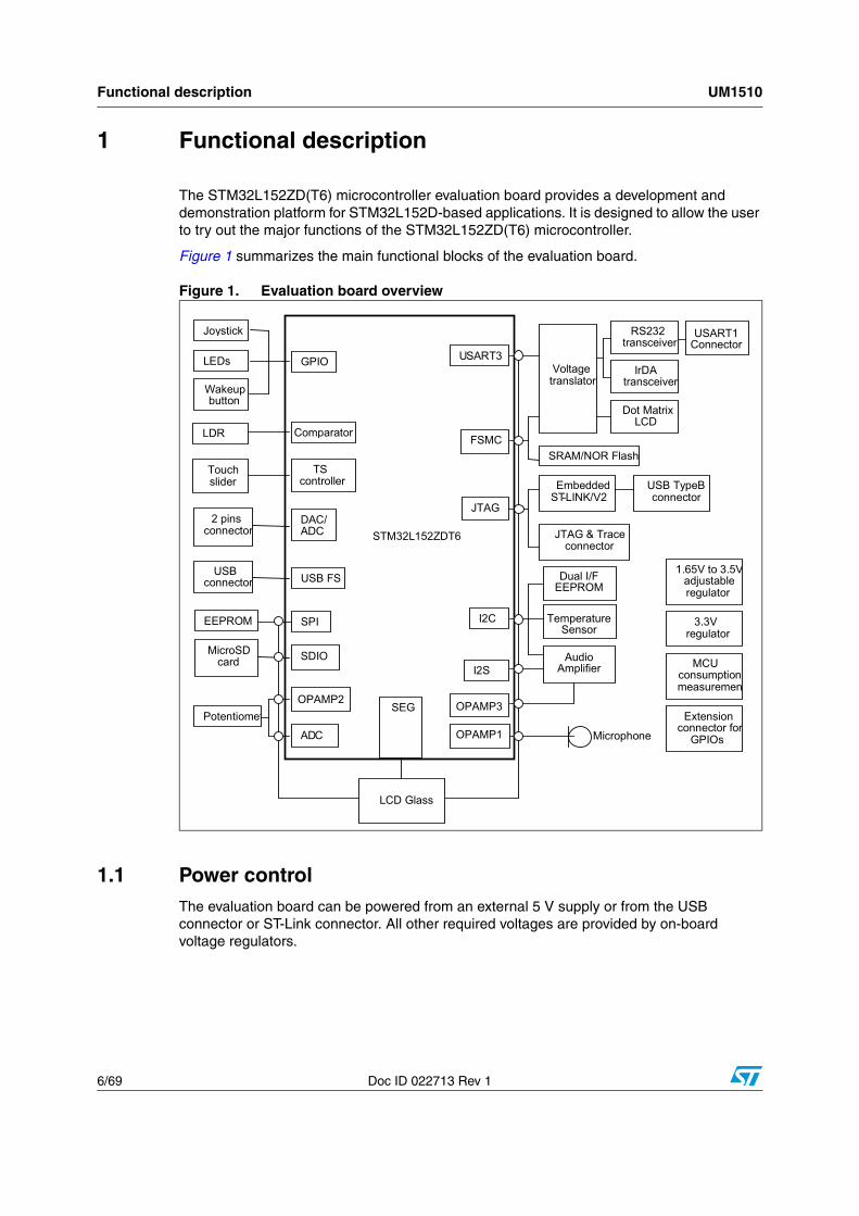
1 Functional description
The STM32L152ZD(T6) microcontroller evaluation board provides a development and demonstration platform for STM32L152D-based applications. It is designed to allow the user to try out the major functions of the STM32L152ZD(T6) microcontroller.
Figure 1 summarizes the main functional blocks of the evaluation board.
Figure 1. Evaluation board overview
1.1 Power controlThe evaluation board can be powered from an external 5 V supply or from the USB connector or ST-Link connector. All other required voltages are provided by on-board voltage regulators.
GPIO
Comparator
TS controller
DAC/ADC
USB FS
SEG
I2C
FSMC
USART3
SPI
ADC
JTAG
Potentiomet
Joystick
LEDs
Wakeup button
LDR
Touch slider
2 pins connector
LCD Glass
USB connector
EEPROM
Voltage translator
RS232 transceiver
IrDA transceiver
Dot Matrix LCD
SRAM/NOR Flash
SDIO MicroSD card
I2S
Embedded ST-LINK/V2
USB TypeB connector
JTAG & Trace connector
1.65V to 3.5Vadjustable regulator
3.3V regulator
MCU consumption measuremen
Extension connector for
GPIOs Microphone
STM32L152ZDT6
AudioAmplifier
USART1Connector
Dual I/FEEPROM
TemperatureSensor
OPAMP1
OPAMP3OPAMP2
UM1510 Functional description
Doc ID 022713 Rev 1 7/69
1.2 ClockingTwo clock sources are available on the STM32L152D-EVAL evaluation board:
● 32 kHz crystal for embedded RTC and glass LCD
● 8 MHz crystal for the STM32L152ZD main clock system
1.3 Reset controlThe reset can be generated by hardware or software:
● Reset button: activates the RESET input when pressed
● JTAG reset
1.4 Debug JTAG interfaceSoftware debug is done via the standard ARM® JTAG connection: 20-pin IDC (insulation displacement connector) for connection to the standard ARM host interface.
1.5 Serial wire debugger interfaceThe Serial Wire Debug Port (SWD-DP) provides a 2-pin (clock + data) interface to the AHP-AP port.
1.6 Embedded ST-LINKAn embedded ST-LINK is integrated on the board as an embedded in-circuit debugger and programmer for the STM32L152ZD MCU.
1.7 Display devices
1.7.1 LCD
A color LCD module is mounted on the STM32L152D-EVAL board. It is interfaced through the embedded FSMC peripheral.
1.7.2 LCD Glass
An LCD Glass module is mounted on the STM32L152D-EVAL board. It is interfaced through the embedded LCD Glass peripheral.
1.7.3 LEDs
Four general-purpose LEDs are available. They are used as a display.
Functional description UM1510
8/69 Doc ID 022713 Rev 1
1.8 Interfaces
1.8.1 RS232
The STM32L152 evaluation board (STM32L152D-EVAL) provides one on-board RS-232 serial port. RS232 port (USART1) is accessed via CN1 connectors.
1.9 IrDA The STM32L152D-EVAL evaluation board supports IrDA communication. The interface is mounted on USART1.
1.10 Miscellaneous peripherals
1.10.1 Joystick
Four-direction joystick with a selection key.
1.10.2 Push-buttons
The STM32L152D evaluation board (STM32L152D-EVAL) provides only one push-button (key). This key can be used as a user push-button, a tamper push-button or a wakeup push-button (to wake-up the processor from a low-power mode).
1.10.3 12-bit analog-to-digital converter (ADC)
Varistor: ADC channel (ADC1_IN18) connected to an on-board variable resistor. The variable resistor provides a voltage in the range of 0 V to 3.3 V.
1.10.4 Audio
The STM32L152D-EVAL evaluation board supports stereo audio play thanks to an audio DAC CS43L22 connected to both I2S2 ports, and one channel of DAC in microcontroller STM32L152ZD.
For the audio output, an audio jack is available on the board and connected to the CS43L22 output.
The U3 microphone is connected to ADC internal through OPAMP1.
1.10.5 MicroSD card
The STM32L152D-EVAL evaluation board has a MicroSD card connector connected to the SDIO peripheral.
1.10.6 Serial EEPROM
The STM32L152D-EVAL evaluation board includes a serial EEPROM connected to the SPI1 peripheral.
UM1510 Functional description
Doc ID 022713 Rev 1 9/69
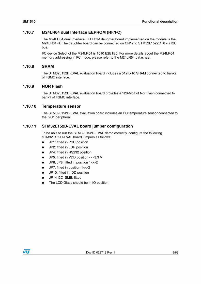
1.10.7 M24LR64 dual Interface EEPROM (RF/I²C)
The M24LR64 dual Interface EEPROM daughter board implemented on the module is the M24LR64-R. The daughter board can be connected on CN12 to STM32L152ZDT6 via I2C bus.
I²C device Select of the M24LR64 is 1010 E2E1E0. For more details about the M24LR64 memory addressing in I²C mode, please refer to the M24LR64 datasheet.
1.10.8 SRAM
The STM32L152D-EVAL evaluation board includes a 512Kx16 SRAM connected to bank2 of FSMC interface.
1.10.9 NOR Flash
The STM32L152D-EVAL evaluation board provides a 128-Mbit of Nor Flash connected to bank1 of FSMC interface.
1.10.10 Temperature sensor
The STM32L152D-EVAL evaluation board includes an I2C temperature sensor connected to the I2C1 peripheral.
1.10.11 STM32L152D-EVAL board jumper configuration
To be able to run the STM32L152D-EVAL demo correctly, configure the following STM32L152D-EVAL board jumpers as follows:
● JP1: fitted in PSU position
● JP2: fitted in LDR position
● JP4: fitted in RS232 position
● JP5: fitted in VDD position <->3.3 V
● JP6, JP8: fitted in position 1<->2
● JP7: fitted in position 1<->2
● JP10: fitted in IDD position
● JP14 I2C_SMB: fitted
● The LCD Glass should be in IO position.
Running the demonstration UM1510
10/69 Doc ID 022713 Rev 1
2 Running the demonstration
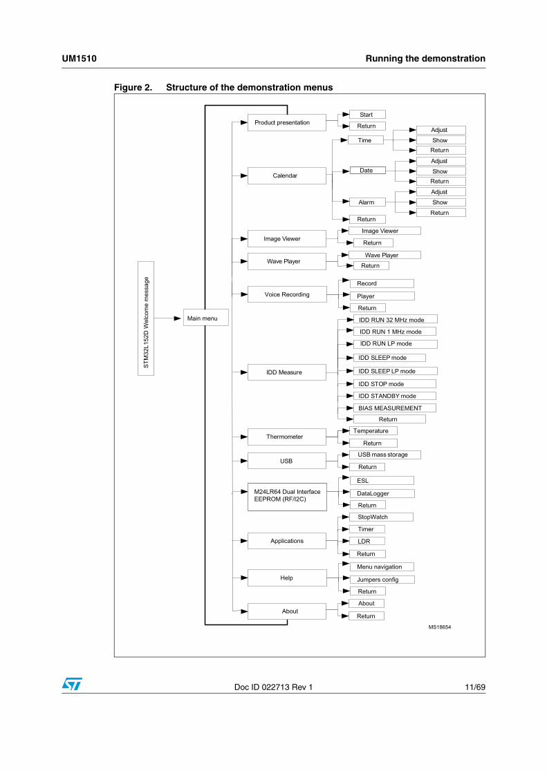
2.1 MenuFigure 2 shows the menu system of the STM32L152D demonstration. The main menu is shown on the left-hand side. The UP, DOWN, RIGHT and LEFT joystick directions allow the user to navigate between items in the main menu and the submenus. To enter a submenu, press the SEL push-button.
The SEL push-button designates the action of vertically pressing the top of the joystick, as opposed to moving it horizontally UP, DOWN, RIGHT or LEFT.
To exit a submenu, select the Return menu and press SEL.
UM1510 Running the demonstration
Doc ID 022713 Rev 1 11/69
Figure 2. Structure of the demonstration menus
STM
32L1
52D
Wel
com
e m
essa
ge
Product presentationStart
Return
CalendarDate
Return
Image ViewerImage Viewer
Wave PlayerReturn
Wave Player
AboutReturn
Adjust
ShowReturn
Time
Adjust
ShowReturn
Alarm
Adjust
Show
Return
ThermometerReturn
Temperature
Help
IDD Measure
Return
Return
IDD SLEEP mode
USBReturn
USB mass storage
IDD SLEEP LP mode
IDD STOP mode
IDD RUN LP mode
IDD STANDBY mode
MS18654
BIAS MEASUREMENT
Applications
Timer
Jumpers config
StopWatch
About
Return
Menu navigation
LDR
Return
M24LR64 Dual Interface EEPROM (RF/I2C)
DataLogger
Return
ESL
Voice Recording
Player
Return
Record
IDD RUN 1 MHz mode
IDD RUN 32 MHz modeMain menu
Running the demonstration UM1510
12/69 Doc ID 022713 Rev 1
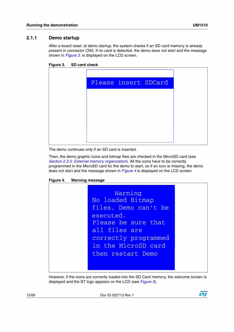
2.1.1 Demo startup
After a board reset, at demo startup, the system checks if an SD card memory is already present in connector CN3. If no card is detected, the demo does not start and the message shown in Figure 3. is displayed on the LCD screen.
Figure 3. SD card check
The demo continues only if an SD card is inserted.
Then, the demo graphic icons and bitmap files are checked in the MicroSD card (see Section 2.3.5: External memory organization). All the icons have to be correctly programmed in the MicroSD card for the demo to start, so if an icon is missing, the demo does not start and the message shown in Figure 4 is displayed on the LCD screen.
Figure 4. Warning message
However, if the icons are correctly loaded into the SD Card memory, the welcome screen is displayed and the ST logo appears on the LCD (see Figure 5).
Please insert SDcardPlease insert SDCard
Warning No loaded Bitmapfiles. Demo can’t beexecuted.Please be sure thatall files are correctly programmedin the MicroSD cardthen restart Demo
UM1510 Running the demonstration
Doc ID 022713 Rev 1 13/69
Figure 5. ST logo
Then, after 1 second, an STM32 presentation slide is displayed on the LCD screen.
Figure 6. STM32L presentation slide
When the board is powered-up for the first time, the user is prompted to set the time, year, month and day. The user may choose to ignore it by pressing any key except for the SEL push-button to abort the configuration sequence. To set the time and date, the user must press SEL and follow the setting sequence.
The message shown in Figure 7 appears on the LCD screen.
Figure 7. Time and date configuration
Note: 1 If the user chooses to configure the time and date, the Time Adjust and Date Adjust menus are displayed. Otherwise, the main menu is displayed and the user can set the time parameters in the Calendar menu. To set the time/date, use the joystick UP/DOWN and SEL push-buttons.
2 If the time configuration has already been done, then the number of elapsed days (higher than 1 day), from the last time the demo board was powered-up, appears on the LCD screen. It is soon followed by the current date.
Running the demonstration UM1510
14/69 Doc ID 022713 Rev 1
Once the time/date have been set, the main menu appears. The main menu is displayed in the form of a set of icons. It shows all the submenus in the same screen. You can navigate using the UP, DOWN, RIGHT and LEFT joystick directions to select the required submenu. To enter a submenu, press the SEL joystick push-button, and the new submenu corresponding to the selected icon is displayed.
Figure 8. Main menu
Note: The icons shown in Figure 8 are taken from http://commons.wikimedia.org/wiki/Crystal_Clear.
Once a submenu has been selected, the name of the application is listed at the top of the display and all the corresponding submenus are listed below, as shown in Figure 9.
Figure 9. Corresponding submenus
2.1.2 Navigation
The demonstration menu is based on circular navigation, submenu selection, item selection and back navigation, as described in Figure 10.

UM1510 Running the demonstration
Doc ID 022713 Rev 1 15/69
Figure 10. Navigating in the demonstration menus
The user navigates using the joystick push-buttons located on the evaluation board: RIGHT, LEFT, SEL, UP and DOWN.
● The UP, DOWN, RIGHT and LEFT push-buttons are used to perform circular navigation in the main menu and the current menu items.
● The SEL push-button selects the current item.
● The UP and DOWN push-buttons are used for vertical navigation in the submenus.
● To return to the upper menu, go to the Return line and press SEL.
Item 1 Item 2 Item 3 Item 4
Item 5 Item 6 Item 7 Item 8
Item 9 Item 10 Item 11 Item 12
Item 3
Item 3.1
RightLeft
RightLeft
RightLeft
RightLeft
RightLeft
RightLeft
RightLeft
RightLeft
RightLeft
Left
Left
Left
Right
Right
Dow
nU
p
Dow
nU
p
Dow
nU
p
Dow
nU
p
Dow
nU
p
Dow
nU
p
Dow
nU
p
Dow
nU
p
Up
Up
Up
Up
Right
Down Down Down Down
Item 3.2
Item 3.n
Return
...
Item 3.1.1
Item 3.1.2
Item 3.1.n
Return
...
Select
Select
Select
ai15162
Running the demonstration UM1510
16/69 Doc ID 022713 Rev 1
2.2 Clock sources
2.2.1 Clock control
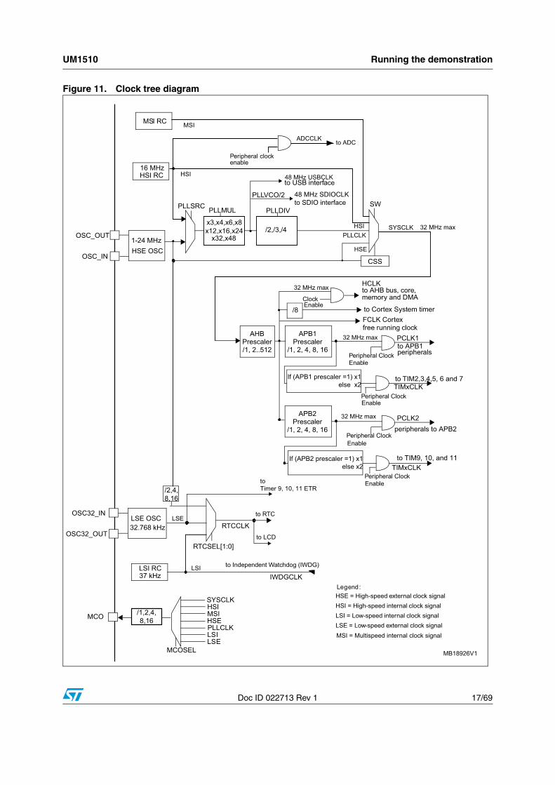
The STM32L152ZD’s internal clocks are derived from the HSE (clocked by the external 8 MHz crystal).
In this demo application, the various system clocks are configured as follows:
● System clock is set to 32 MHz: the PLL is used as the system clock source: 32 MHz (1 wait state, Flash memory prefetch buffer enabled).
● HCLK frequency is set to 32 MHz.
● Timer clock (TIMCLK) is set to 32 MHz.
● USB clock is set to 48 MHz.
● ADC clock is set to 16 MHz.
● PCLK1 is set to 32 MHz.
● PCLK2 is set to 32 MHz.
Only the RTC is clocked by a 32 kHz external oscillator.
Figure 11 illustrates the clock tree organization for this demo.
UM1510 Running the demonstration
Doc ID 022713 Rev 1 17/69
Figure 11. Clock tree diagram
AHBPrescaler/1, 2..512
APB1Prescaler
/1, 2, 4, 8, 16
PCLK1
HCLKto AHB bus, core, memory and DMA
peripheralsto APB1
Peripheral Clock Enable
EnablePeripheral Clock
APB2Prescaler
/1, 2, 4, 8, 16
PCLK2
to TIM9, 10, and 11
peripherals to APB2Peripheral Clock Enable
EnablePeripheral Clock
32 MHz max
32 MHz max
to Cortex System timer/8Clock Enable
SYSCLK
TIMxCLK
TIMxCLK
FCLK Cortexfree running clock
to TIM2,3,4,5, 6 and 7If (APB1 prescaler =1) x1else x2
If (APB2 prescaler =1) x1else x2
32 MHz max
HSE OSC1-24 MHz
OSC_IN
OSC_OUT
HSI RC 16 MHz
x3,x4,x6,x8x12,x16,x24
PLLMUL
PLLCLK
HSI
HSI
HSE
PLLSRC SW
CSS
x32,x48/2,/3,/4
48 MHz USBCLKto USB interface
PLLDIV
to ADC
Peripheral clockenable
ADCCLK
32 MHz max
OSC32_IN
OSC32_OUT
LSE OSC32.768 kHz
LSI RC37 kHz
to Independent Watchdog (IWDG)
MCO PLLCLK
HSI
HSE
LSE
LSI
/2,4,8,16
to RTC
MCOSEL
RTCCLK
RTCSEL[1:0]
IWDGCLK
SYSCLK
/1,2,4,8,16
MSI
LSELSI
to LCD
to Timer 9, 10, 11 ETR
HSE = High-speed external clock signal
LSE = Low -speed external clock signalLSI = Low-speed internal clock signalHSI = High-speed internal clock signal
Legend:
MB18926V1
MS I = Multispeed internal clock signal
PLLVCO/2
MSI RC MSI
48 MHz SDIOCLK to SDIO interface
Running the demonstration UM1510
18/69 Doc ID 022713 Rev 1
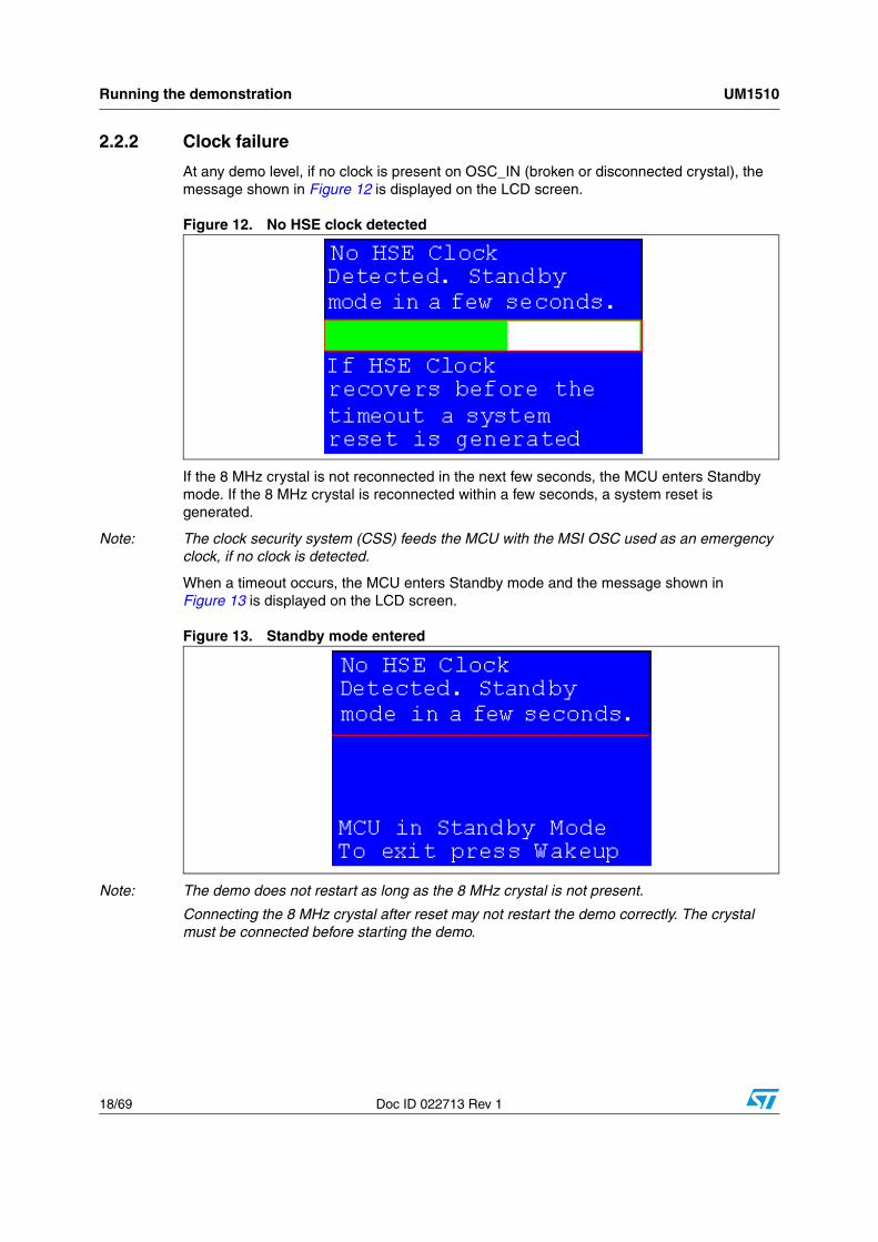
2.2.2 Clock failure
At any demo level, if no clock is present on OSC_IN (broken or disconnected crystal), the message shown in Figure 12 is displayed on the LCD screen.
Figure 12. No HSE clock detected
If the 8 MHz crystal is not reconnected in the next few seconds, the MCU enters Standby mode. If the 8 MHz crystal is reconnected within a few seconds, a system reset is generated.
Note: The clock security system (CSS) feeds the MCU with the MSI OSC used as an emergency clock, if no clock is detected.
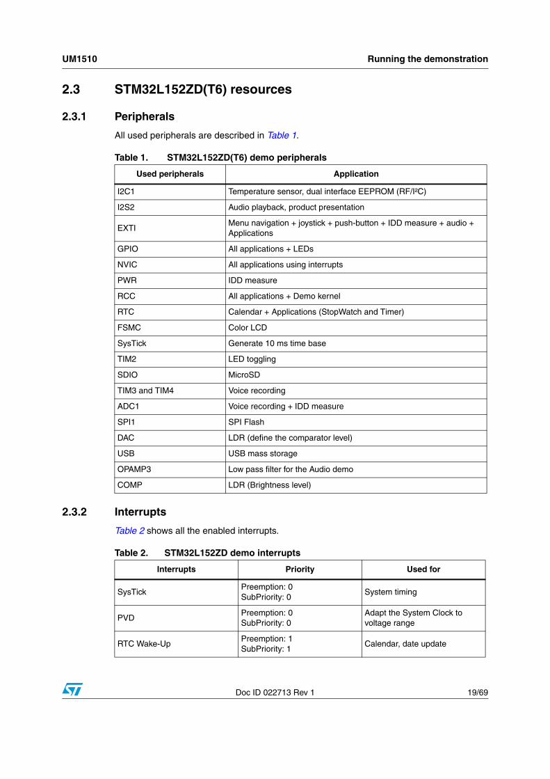
When a timeout occurs, the MCU enters Standby mode and the message shown in Figure 13 is displayed on the LCD screen.
Figure 13. Standby mode entered
Note: The demo does not restart as long as the 8 MHz crystal is not present.
Connecting the 8 MHz crystal after reset may not restart the demo correctly. The crystal must be connected before starting the demo.
UM1510 Running the demonstration
Doc ID 022713 Rev 1 19/69
2.3 STM32L152ZD(T6) resources
2.3.1 Peripherals
All used peripherals are described in Table 1.
2.3.2 Interrupts
Table 2 shows all the enabled interrupts.
Table 1. STM32L152ZD(T6) demo peripherals
Used peripherals Application
I2C1 Temperature sensor, dual interface EEPROM (RF/I²C)
I2S2 Audio playback, product presentation
EXTIMenu navigation + joystick + push-button + IDD measure + audio + Applications
GPIO All applications + LEDs
NVIC All applications using interrupts
PWR IDD measure
RCC All applications + Demo kernel
RTC Calendar + Applications (StopWatch and Timer)
FSMC Color LCD
SysTick Generate 10 ms time base
TIM2 LED toggling
SDIO MicroSD
TIM3 and TIM4 Voice recording
ADC1 Voice recording + IDD measure
SPI1 SPI Flash
DAC LDR (define the comparator level)
USB USB mass storage
OPAMP3 Low pass filter for the Audio demo
COMP LDR (Brightness level)
Table 2. STM32L152ZD demo interrupts
Interrupts Priority Used for
SysTickPreemption: 0SubPriority: 0
System timing
PVDPreemption: 0SubPriority: 0
Adapt the System Clock to voltage range
RTC Wake-UpPreemption: 1SubPriority: 1
Calendar, date update
Running the demonstration UM1510
20/69 Doc ID 022713 Rev 1
2.3.3 External interrupts
NMI Preemption(fixed): -2 CSS interrupt
EXTI0Preemption: 0SubPriority: 0
Wake-Up button
EXTI9_5Preemption: 3SubPriority: 2
Menu navigation
EXTI15_10Preemption: 2SubPriority: 2
Menu navigation
I2C1 ErrorPreemption: 0SubPriority: 0
SMBus Alert interrupt
TIM4_UPPreemption: 1SubPriority: 0
Enable SDIO write operation
TIM3_UPPreemption: 0SubPriority: 1
Sampling rate
TIM2_UPPreemption: 1SubPriority: 1
LED toggling
RTC Tamper Preemption: 1SubPriority: 1
Tamper generation
RTCAlarmPreemption: 1SubPriority: 1
Alarm generation
COMPPreemption: 2SubPriority: 1
LCD Glass contrast adjust
SDIOPreemption: 0SubPriority: 0
Writing in the SDIO
DMA1Preemption: 0SubPriority: 0
DMA1 transfer comp
SPI2Preemption: 0SubPriority: 0
I2S interrupt
USBPreemption: 0SubPriority: 0
USB sub-Demo
Table 2. STM32L152ZD demo interrupts (continued)
Interrupts Priority Used for
Table 3. STM32L152ZD demo external interrupts
External interrupts Used for
EXTI line 13 Joystick SEL (interrupt mode, falling edge)
EXTI line 11 Joystick UP (interrupt mode, falling edge)
EXTI line 6 Joystick LEFT (interrupt mode, falling edge)
EXTI line 7 Joystick RIGHT (interrupt mode, falling edge)
EXTI line 8 Joystick DOWN (interrupt mode, falling edge)
EXTI line 0 User Button (interrupt mode, falling edge)
UM1510 Running the demonstration
Doc ID 022713 Rev 1 21/69
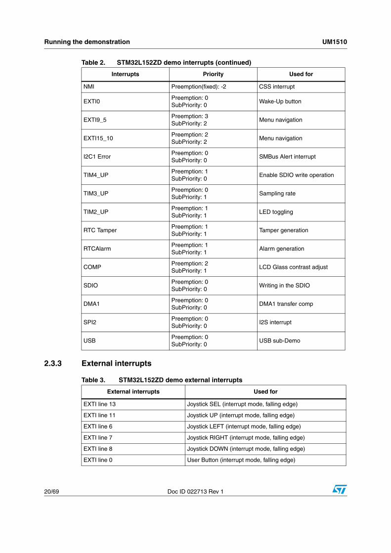
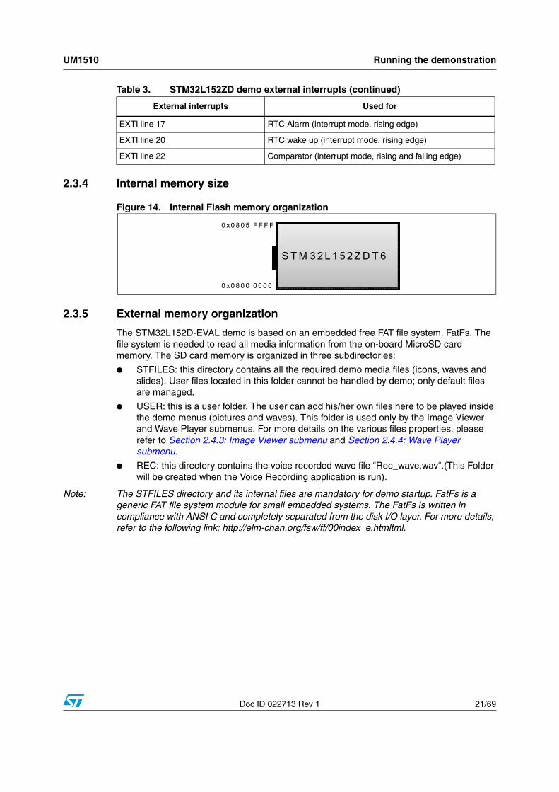
2.3.4 Internal memory size
Figure 14. Internal Flash memory organization
2.3.5 External memory organization
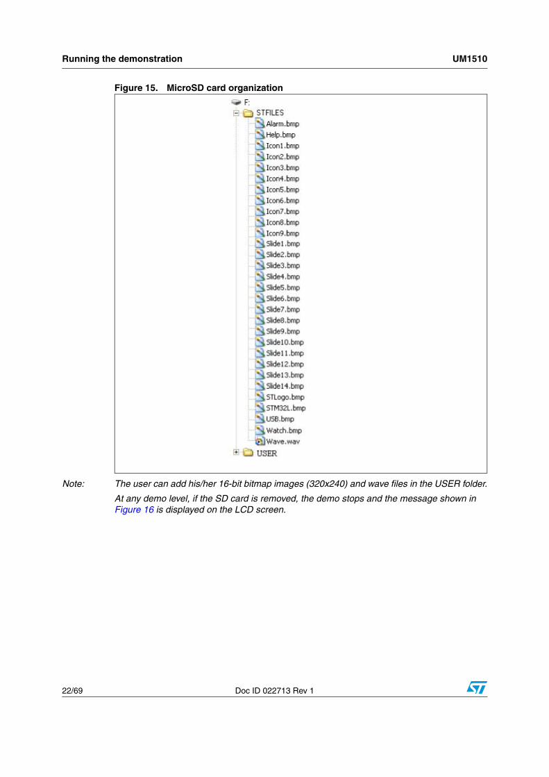
The STM32L152D-EVAL demo is based on an embedded free FAT file system, FatFs. The file system is needed to read all media information from the on-board MicroSD card memory. The SD card memory is organized in three subdirectories:
● STFILES: this directory contains all the required demo media files (icons, waves and slides). User files located in this folder cannot be handled by demo; only default files are managed.
● USER: this is a user folder. The user can add his/her own files here to be played inside the demo menus (pictures and waves). This folder is used only by the Image Viewer and Wave Player submenus. For more details on the various files properties, please refer to Section 2.4.3: Image Viewer submenu and Section 2.4.4: Wave Player submenu.
● REC: this directory contains the voice recorded wave file “Rec_wave.wav“.(This Folder will be created when the Voice Recording application is run).
Note: The STFILES directory and its internal files are mandatory for demo startup. FatFs is a generic FAT file system module for small embedded systems. The FatFs is written in compliance with ANSI C and completely separated from the disk I/O layer. For more details, refer to the following link: http://elm-chan.org/fsw/ff/00index_e.htmltml.
EXTI line 17 RTC Alarm (interrupt mode, rising edge)
EXTI line 20 RTC wake up (interrupt mode, rising edge)
EXTI line 22 Comparator (interrupt mode, rising and falling edge)
Table 3. STM32L152ZD demo external interrupts (continued)
External interrupts Used for
S T M 3 2 L 1 5 2 Z D T 6
0 x 0 8 0 0 0 0 0 0
0 x 0 8 0 5 F F F F
Running the demonstration UM1510
22/69 Doc ID 022713 Rev 1
Figure 15. MicroSD card organization
Note: The user can add his/her 16-bit bitmap images (320x240) and wave files in the USER folder.
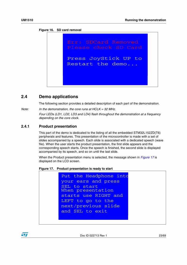
At any demo level, if the SD card is removed, the demo stops and the message shown in Figure 16 is displayed on the LCD screen.
UM1510 Running the demonstration
Doc ID 022713 Rev 1 23/69
Figure 16. SD card removal
2.4 Demo applicationsThe following section provides a detailed description of each part of the demonstration.
Note: In the demonstration, the core runs at HCLK = 32 MHz.
Four LEDs (LD1, LD2, LD3 and LD4) flash throughout the demonstration at a frequency depending on the core clock.
2.4.1 Product presentation
This part of the demo is dedicated to the listing of all the embedded STM32L152ZD(T6) peripherals and features. This presentation of the microcontroller is made with a set of slides accompanied by a speech. Each slide is associated with a dedicated speech (wave file). When the user starts the product presentation, the first slide appears and the corresponding speech starts. Once the speech is finished, the second slide is displayed accompanied by its speech, and so on until the last slide.
When the Product presentation menu is selected, the message shown in Figure 17 is displayed on the LCD screen.
Figure 17. Product presentation is ready to start
Err: SDCard Removed
Please check SD Card
Press JoyStick UP toRestart the demo...
Put the Headphone into
When presentationstarts use RIGHT and LEFT to go to thenext/previous slideand SEL to exit
your ears and press SEL to start
Running the demonstration UM1510
24/69 Doc ID 022713 Rev 1
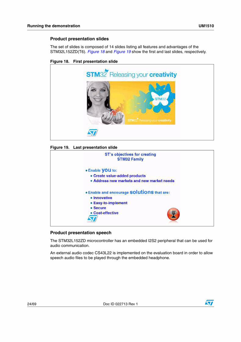
Product presentation slides
The set of slides is composed of 14 slides listing all features and advantages of the STM32L152ZD(T6). Figure 18 and Figure 19 show the first and last slides, respectively.
Figure 18. First presentation slide
Figure 19. Last presentation slide
Product presentation speech
The STM32L152ZD microcontroller has an embedded I2S2 peripheral that can be used for audio communication.
An external audio codec CS43L22 is implemented on the evaluation board in order to allow speech audio files to be played through the embedded headphone.
UM1510 Running the demonstration
Doc ID 022713 Rev 1 25/69
The properties of the product presentation speech wave files are the following:
● Playing time: 6 min 16 s
● File number: 14 wave files
● File names: WAVE_Si (i designed the slide index)
● Format tag: PCM
● Channels: Stereo
● Sample rate: 8 kHz
● Bits per sample: 16 bits
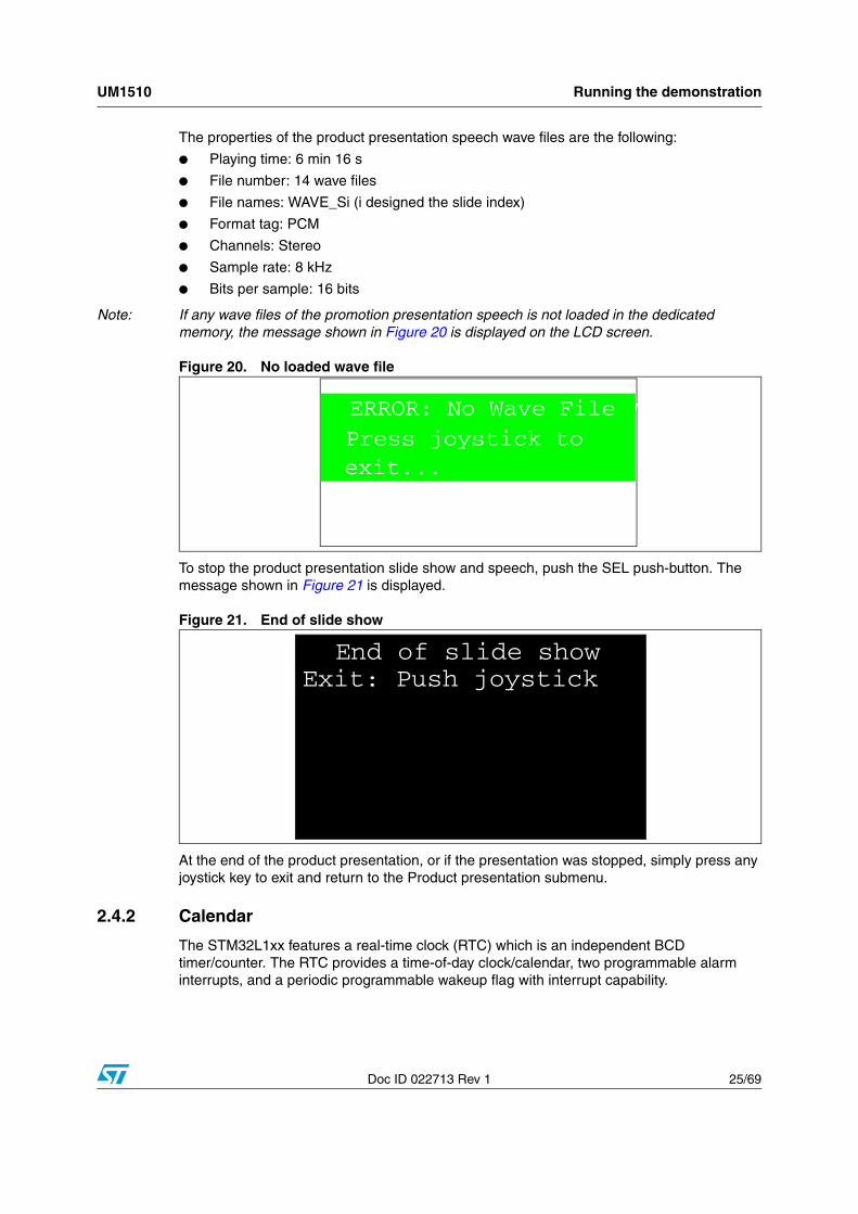
Note: If any wave files of the promotion presentation speech is not loaded in the dedicated memory, the message shown in Figure 20 is displayed on the LCD screen.
Figure 20. No loaded wave file
To stop the product presentation slide show and speech, push the SEL push-button. The message shown in Figure 21 is displayed.
Figure 21. End of slide show
At the end of the product presentation, or if the presentation was stopped, simply press any joystick key to exit and return to the Product presentation submenu.
2.4.2 Calendar
The STM32L1xx features a real-time clock (RTC) which is an independent BCD timer/counter. The RTC provides a time-of-day clock/calendar, two programmable alarm interrupts, and a periodic programmable wakeup flag with interrupt capability.
End of slide showClick to exitERROR: No Wave File
Press joystick to exit...
End of slide showExit: Push joystick
Running the demonstration UM1510
26/69 Doc ID 022713 Rev 1
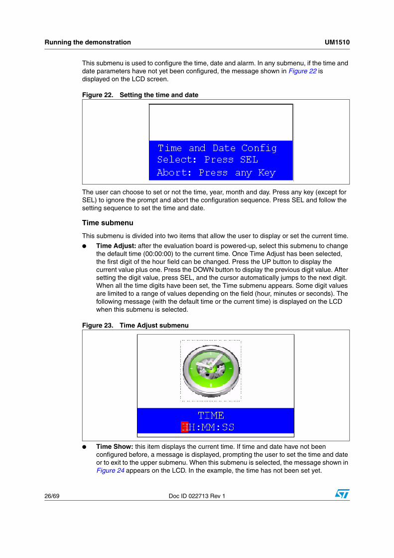
This submenu is used to configure the time, date and alarm. In any submenu, if the time and date parameters have not yet been configured, the message shown in Figure 22 is displayed on the LCD screen.
Figure 22. Setting the time and date
The user can choose to set or not the time, year, month and day. Press any key (except for SEL) to ignore the prompt and abort the configuration sequence. Press SEL and follow the setting sequence to set the time and date.
Time submenu
This submenu is divided into two items that allow the user to display or set the current time.
● Time Adjust: after the evaluation board is powered-up, select this submenu to change the default time (00:00:00) to the current time. Once Time Adjust has been selected, the first digit of the hour field can be changed. Press the UP button to display the current value plus one. Press the DOWN button to display the previous digit value. After setting the digit value, press SEL, and the cursor automatically jumps to the next digit. When all the time digits have been set, the Time submenu appears. Some digit values are limited to a range of values depending on the field (hour, minutes or seconds). The following message (with the default time or the current time) is displayed on the LCD when this submenu is selected.
Figure 23. Time Adjust submenu
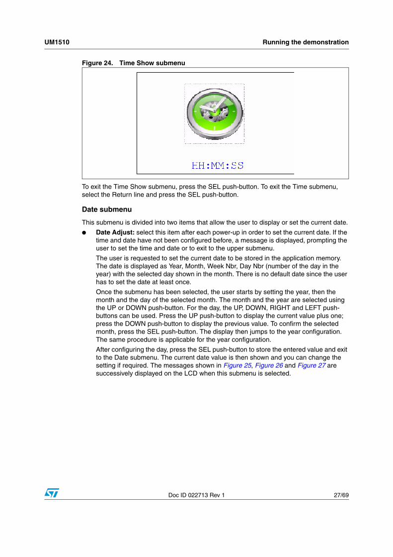
● Time Show: this item displays the current time. If time and date have not been configured before, a message is displayed, prompting the user to set the time and date or to exit to the upper submenu. When this submenu is selected, the message shown in Figure 24 appears on the LCD. In the example, the time has not been set yet.
UM1510 Running the demonstration
Doc ID 022713 Rev 1 27/69
Figure 24. Time Show submenu
To exit the Time Show submenu, press the SEL push-button. To exit the Time submenu, select the Return line and press the SEL push-button.
Date submenu
This submenu is divided into two items that allow the user to display or set the current date.
● Date Adjust: select this item after each power-up in order to set the current date. If the time and date have not been configured before, a message is displayed, prompting the user to set the time and date or to exit to the upper submenu.
The user is requested to set the current date to be stored in the application memory. The date is displayed as Year, Month, Week Nbr, Day Nbr (number of the day in the year) with the selected day shown in the month. There is no default date since the user has to set the date at least once.
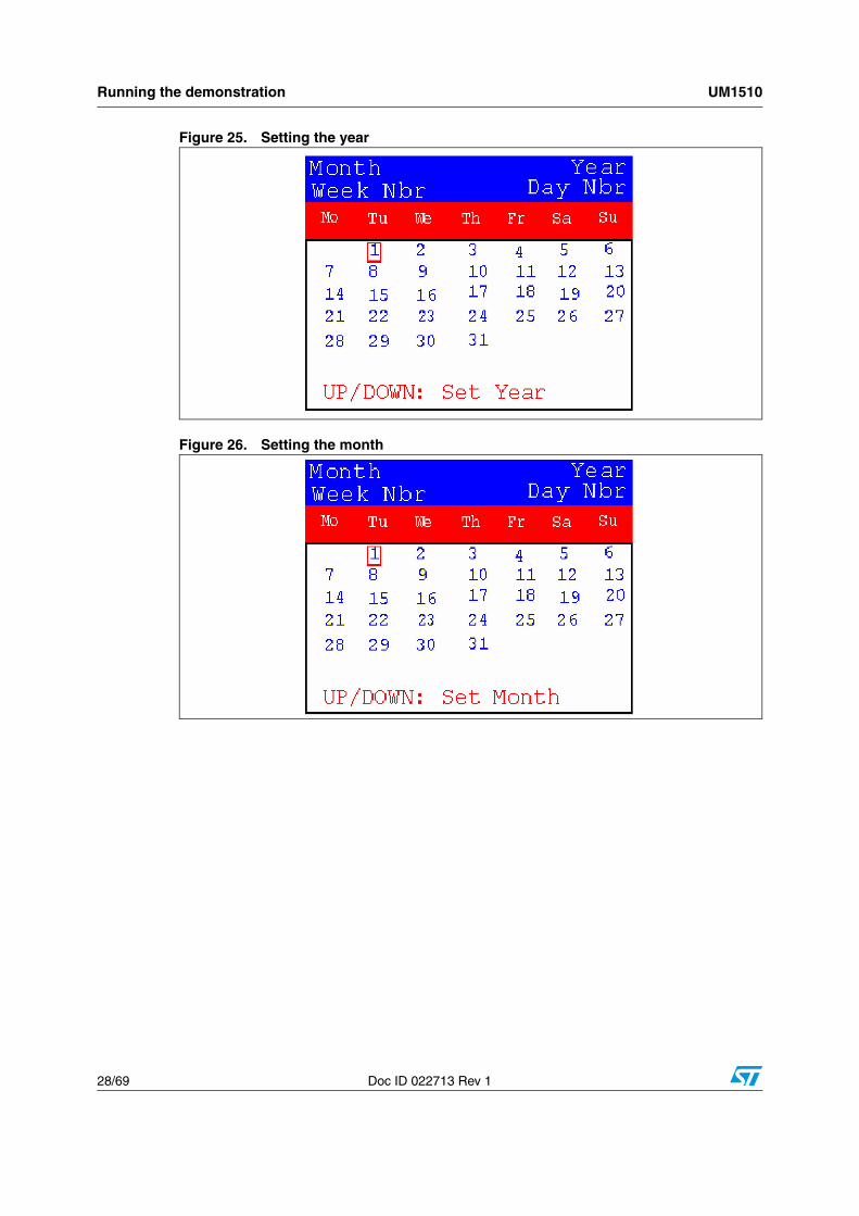
Once the submenu has been selected, the user starts by setting the year, then the month and the day of the selected month. The month and the year are selected using the UP or DOWN push-button. For the day, the UP, DOWN, RIGHT and LEFT push-buttons can be used. Press the UP push-button to display the current value plus one; press the DOWN push-button to display the previous value. To confirm the selected month, press the SEL push-button. The display then jumps to the year configuration. The same procedure is applicable for the year configuration.
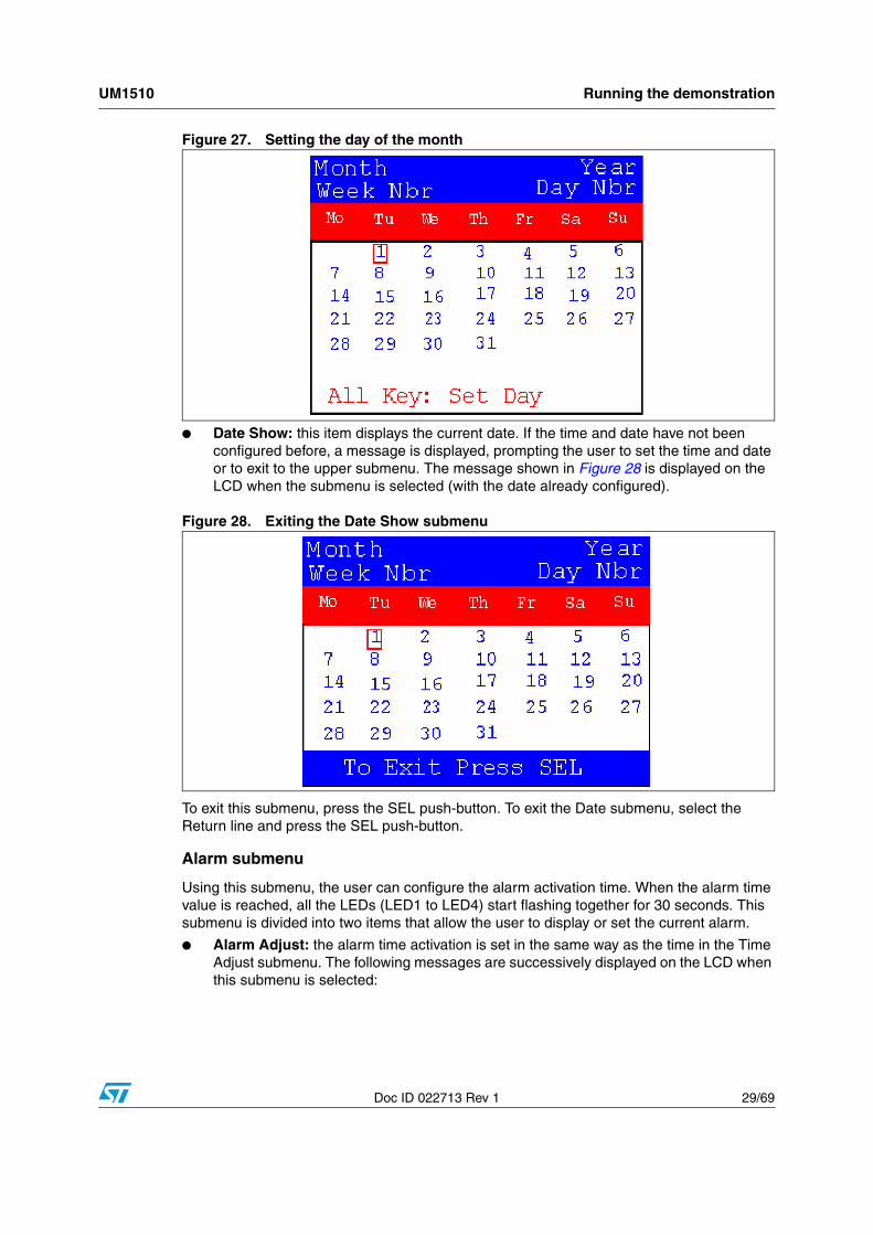
After configuring the day, press the SEL push-button to store the entered value and exit to the Date submenu. The current date value is then shown and you can change the setting if required. The messages shown in Figure 25, Figure 26 and Figure 27 are successively displayed on the LCD when this submenu is selected.
Running the demonstration UM1510
28/69 Doc ID 022713 Rev 1
Figure 25. Setting the year
Figure 26. Setting the month
UM1510 Running the demonstration
Doc ID 022713 Rev 1 29/69
Figure 27. Setting the day of the month
● Date Show: this item displays the current date. If the time and date have not been configured before, a message is displayed, prompting the user to set the time and date or to exit to the upper submenu. The message shown in Figure 28 is displayed on the LCD when the submenu is selected (with the date already configured).
Figure 28. Exiting the Date Show submenu
To exit this submenu, press the SEL push-button. To exit the Date submenu, select the Return line and press the SEL push-button.
Alarm submenu
Using this submenu, the user can configure the alarm activation time. When the alarm time value is reached, all the LEDs (LED1 to LED4) start flashing together for 30 seconds. This submenu is divided into two items that allow the user to display or set the current alarm.
● Alarm Adjust: the alarm time activation is set in the same way as the time in the Time Adjust submenu. The following messages are successively displayed on the LCD when this submenu is selected:

Running the demonstration UM1510
30/69 Doc ID 022713 Rev 1
Figure 29. Setting the alarm activation time
● Alarm Show: this item displays the current alarm time. The default Alarm activation time displayed after power-up and before setting in the Alarm Adjust submenu is 00:00:00. If the time and date have not been configured before, a message shown in Figure 31 is displayed. Pressing SEL takes you back to the Alarm submenu. The message shown in Figure 30 is displayed on the LCD when this submenu is selected.
Figure 30. Alarm Show submenu
To exit the Alarm Show submenu, press the SEL push-button. To exit the Alarm submenu, select the Return line and press the SEL push-button.
Note: In the Alarm Adjust and Alarm Show menus, if the time and date have not yet been configured, the message shown in Figure 31 is displayed on the LCD screen.
UM1510 Running the demonstration
Doc ID 022713 Rev 1 31/69
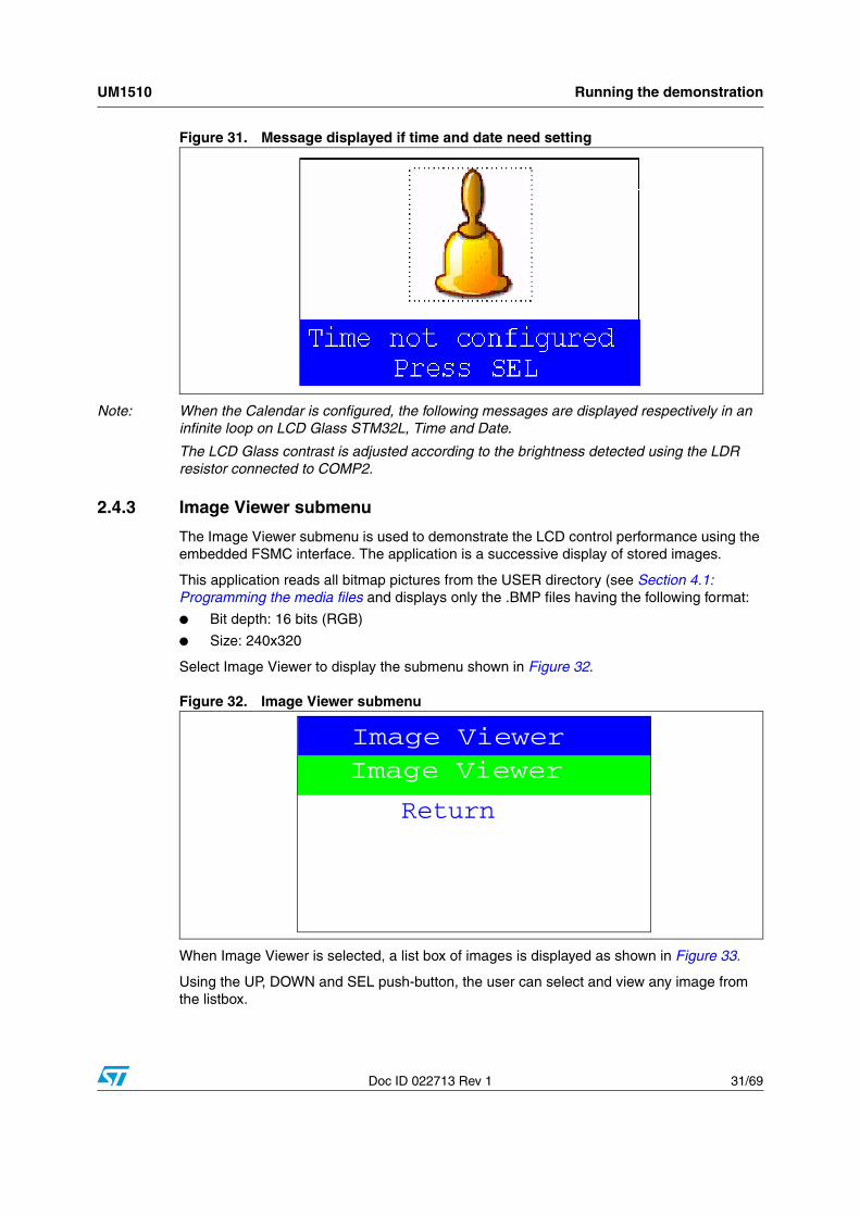
Figure 31. Message displayed if time and date need setting
Note: When the Calendar is configured, the following messages are displayed respectively in an infinite loop on LCD Glass STM32L, Time and Date.
The LCD Glass contrast is adjusted according to the brightness detected using the LDR resistor connected to COMP2.
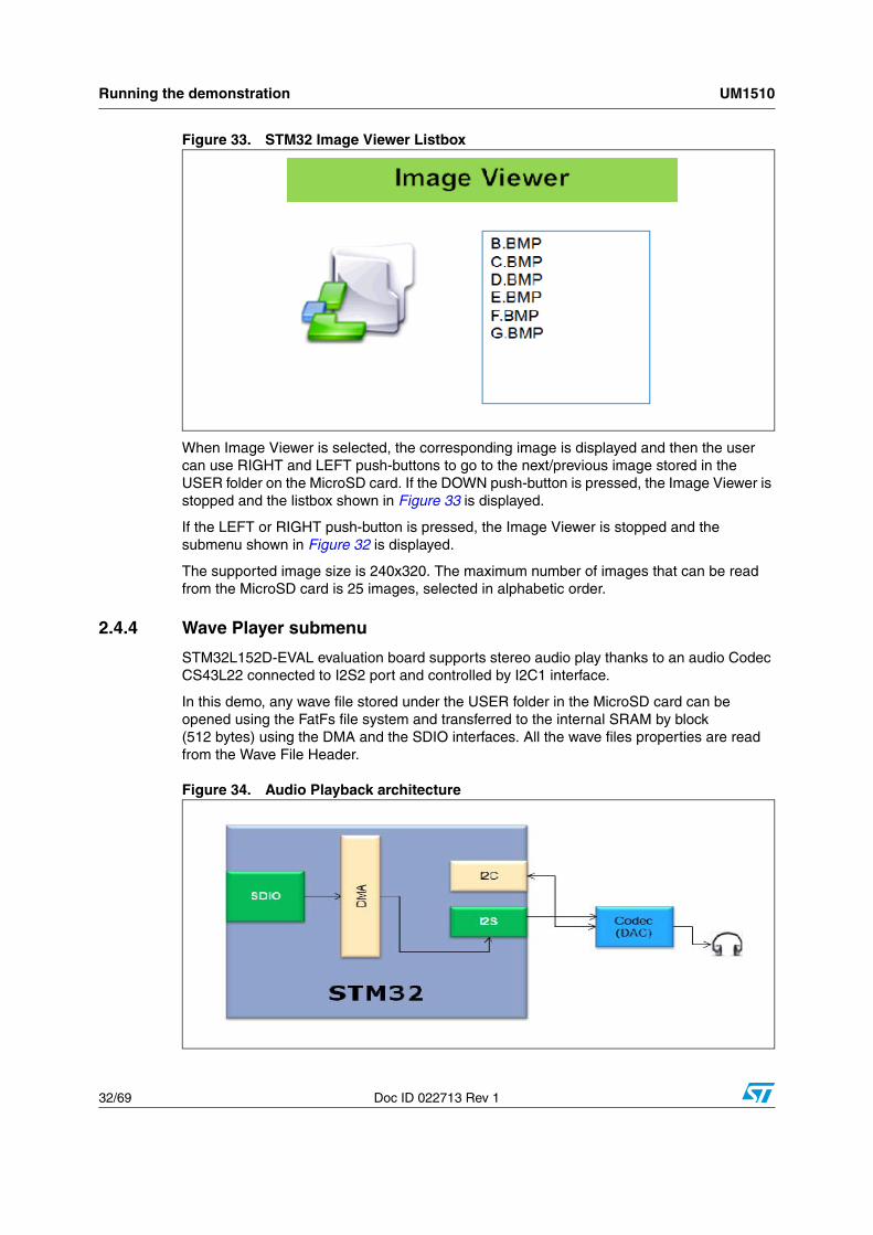
2.4.3 Image Viewer submenu
The Image Viewer submenu is used to demonstrate the LCD control performance using the embedded FSMC interface. The application is a successive display of stored images.
This application reads all bitmap pictures from the USER directory (see Section 4.1: Programming the media files and displays only the .BMP files having the following format:
● Bit depth: 16 bits (RGB)
● Size: 240x320
Select Image Viewer to display the submenu shown in Figure 32.
Figure 32. Image Viewer submenu
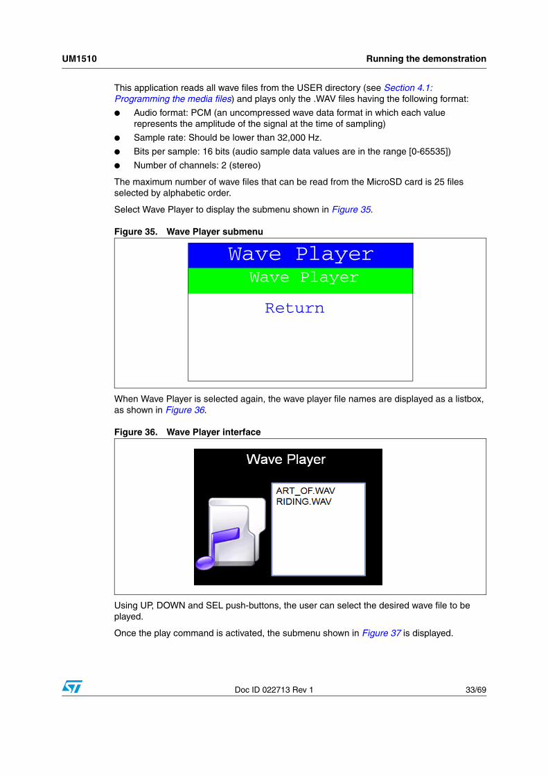
When Image Viewer is selected, a list box of images is displayed as shown in Figure 33.
Using the UP, DOWN and SEL push-button, the user can select and view any image from the listbox.
Image Viewer
Return
Image Viewer
Running the demonstration UM1510
32/69 Doc ID 022713 Rev 1
Figure 33. STM32 Image Viewer Listbox
When Image Viewer is selected, the corresponding image is displayed and then the user can use RIGHT and LEFT push-buttons to go to the next/previous image stored in the USER folder on the MicroSD card. If the DOWN push-button is pressed, the Image Viewer is stopped and the listbox shown in Figure 33 is displayed.
If the LEFT or RIGHT push-button is pressed, the Image Viewer is stopped and the submenu shown in Figure 32 is displayed.
The supported image size is 240x320. The maximum number of images that can be read from the MicroSD card is 25 images, selected in alphabetic order.
2.4.4 Wave Player submenu
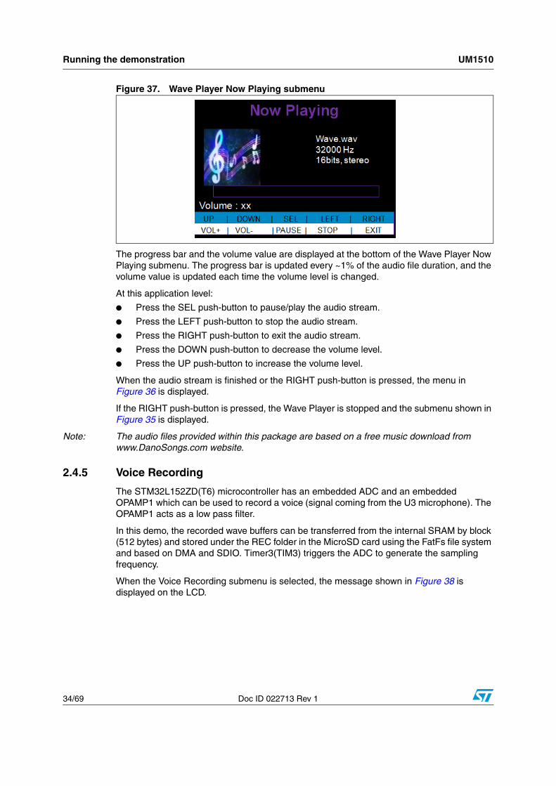
STM32L152D-EVAL evaluation board supports stereo audio play thanks to an audio Codec CS43L22 connected to I2S2 port and controlled by I2C1 interface.
In this demo, any wave file stored under the USER folder in the MicroSD card can be opened using the FatFs file system and transferred to the internal SRAM by block (512 bytes) using the DMA and the SDIO interfaces. All the wave files properties are read from the Wave File Header.
Figure 34. Audio Playback architecture
APP Main Menu Name
UM1510 Running the demonstration
Doc ID 022713 Rev 1 33/69
This application reads all wave files from the USER directory (see Section 4.1: Programming the media files) and plays only the .WAV files having the following format:
● Audio format: PCM (an uncompressed wave data format in which each value represents the amplitude of the signal at the time of sampling)
● Sample rate: Should be lower than 32,000 Hz.
● Bits per sample: 16 bits (audio sample data values are in the range [0-65535])
● Number of channels: 2 (stereo)
The maximum number of wave files that can be read from the MicroSD card is 25 files selected by alphabetic order.
Select Wave Player to display the submenu shown in Figure 35.
Figure 35. Wave Player submenu
When Wave Player is selected again, the wave player file names are displayed as a listbox, as shown in Figure 36.
Figure 36. Wave Player interface
Using UP, DOWN and SEL push-buttons, the user can select the desired wave file to be played.
Once the play command is activated, the submenu shown in Figure 37 is displayed.
Wave Player
Return
Wave Player
Running the demonstration UM1510
34/69 Doc ID 022713 Rev 1
Figure 37. Wave Player Now Playing submenu
The progress bar and the volume value are displayed at the bottom of the Wave Player Now Playing submenu. The progress bar is updated every ~1% of the audio file duration, and the volume value is updated each time the volume level is changed.
At this application level:
● Press the SEL push-button to pause/play the audio stream.
● Press the LEFT push-button to stop the audio stream.
● Press the RIGHT push-button to exit the audio stream.
● Press the DOWN push-button to decrease the volume level.
● Press the UP push-button to increase the volume level.
When the audio stream is finished or the RIGHT push-button is pressed, the menu in Figure 36 is displayed.
If the RIGHT push-button is pressed, the Wave Player is stopped and the submenu shown in Figure 35 is displayed.
Note: The audio files provided within this package are based on a free music download from www.DanoSongs.com website.
2.4.5 Voice Recording
The STM32L152ZD(T6) microcontroller has an embedded ADC and an embedded OPAMP1 which can be used to record a voice (signal coming from the U3 microphone). The OPAMP1 acts as a low pass filter.
In this demo, the recorded wave buffers can be transferred from the internal SRAM by block (512 bytes) and stored under the REC folder in the MicroSD card using the FatFs file system and based on DMA and SDIO. Timer3(TIM3) triggers the ADC to generate the sampling frequency.
When the Voice Recording submenu is selected, the message shown in Figure 38 is displayed on the LCD.
RIGHT FWD

UM1510 Running the demonstration
Doc ID 022713 Rev 1 35/69
Figure 38. Voice Recording submenu selected
If the Record submenu has been selected by pressing the SEL push-button, the Voice Recording interface is displayed, as shown in Figure 39.
Figure 39. Voice Recording submenu
Once the record command is activated (by pressing the SEL push-button), the submenu shown in Figure 40 is displayed.
Voice RecordingRecordPlayerReturn
Running the demonstration UM1510
36/69 Doc ID 022713 Rev 1
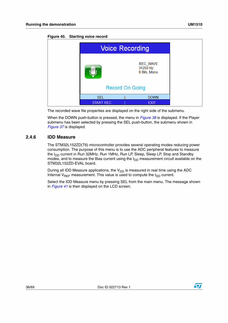
Figure 40. Starting voice record
The recorded wave file properties are displayed on the right side of the submenu.
When the DOWN push-button is pressed, the menu in Figure 38 is displayed. If the Player submenu has been selected by pressing the SEL push-button, the submenu shown in Figure 37 is displayed.
2.4.6 IDD Measure
The STM32L152ZD(T6) microcontroller provides several operating modes reducing power consumption. The purpose of this menu is to use the ADC peripheral features to measure the IDD current in Run 32MHz, Run 1MHz, Run LP, Sleep, Sleep LP, Stop and Standby modes, and to measure the Bias current using the IDD measurement circuit available on the STM32L152ZD-EVAL board.
During all IDD Measure applications, the VDD is measured in real time using the ADC Internal VREF measurement. This value is used to compute the IDD current.
Select the IDD Measure menu by pressing SEL from the main menu. The message shown in Figure 41 is then displayed on the LCD screen.
UM1510 Running the demonstration
Doc ID 022713 Rev 1 37/69
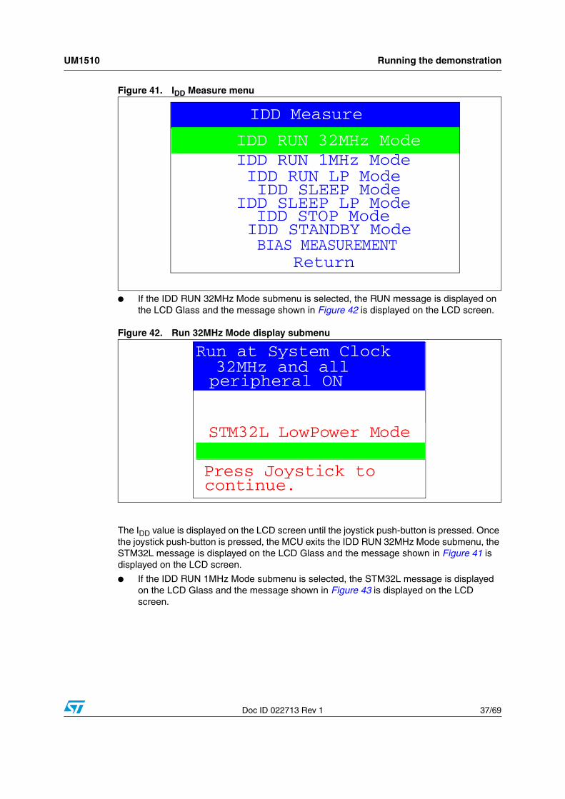
Figure 41. IDD Measure menu
● If the IDD RUN 32MHz Mode submenu is selected, the RUN message is displayed on the LCD Glass and the message shown in Figure 42 is displayed on the LCD screen.
Figure 42. Run 32MHz Mode display submenu
The IDD value is displayed on the LCD screen until the joystick push-button is pressed. Once the joystick push-button is pressed, the MCU exits the IDD RUN 32MHz Mode submenu, the STM32L message is displayed on the LCD Glass and the message shown in Figure 41 is displayed on the LCD screen.
● If the IDD RUN 1MHz Mode submenu is selected, the STM32L message is displayed on the LCD Glass and the message shown in Figure 43 is displayed on the LCD screen.
IDD RUN 32MHz Mode
BIAS MEASUREMENT
IDD RUN 1MHz Mode
IDD SLEEP Mode
IDD Measure
IDD RUN LP Mode
IDD STOP ModeIDD SLEEP LP Mode
IDD STANDBY Mode
Return
Run at System Clock
To exit pressJoystick
32MHz and allperipheral ON
IDD: xxx,xxx mASTM32L LowPower Mode
Press Joystick tocontinue.
Running the demonstration UM1510
38/69 Doc ID 022713 Rev 1
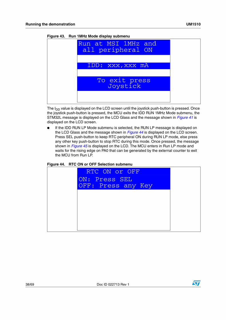
Figure 43. Run 1MHz Mode display submenu
The IDD value is displayed on the LCD screen until the joystick push-button is pressed. Once the joystick push-button is pressed, the MCU exits the IDD RUN 1MHz Mode submenu, the STM32L message is displayed on the LCD Glass and the message shown in Figure 41 is displayed on the LCD screen.
● If the IDD RUN LP Mode submenu is selected, the RUN LP message is displayed on the LCD Glass and the message shown in Figure 44 is displayed on the LCD screen. Press SEL push-button to keep RTC peripheral ON during RUN LP mode, else press any other key push-button to stop RTC during this mode. Once pressed, the message shown in Figure 45 is displayed on the LCD. The MCU enters in Run LP mode and waits for the rising edge on PA0 that can be generated by the external counter to exit the MCU from Run LP.
Figure 44. RTC ON or OFF Selection submenu
Run at MSI 1MHz and
To exit pressJoystick
all peripheral ON
IDD: xxx,xxx mA
RTC ON or OFF
OFF: Press any KeyON: Press SEL
UM1510 Running the demonstration
Doc ID 022713 Rev 1 39/69
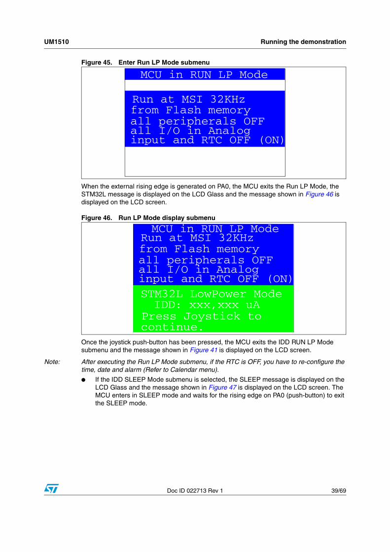
Figure 45. Enter Run LP Mode submenu
When the external rising edge is generated on PA0, the MCU exits the Run LP Mode, the STM32L message is displayed on the LCD Glass and the message shown in Figure 46 is displayed on the LCD screen.
Figure 46. Run LP Mode display submenu
Once the joystick push-button has been pressed, the MCU exits the IDD RUN LP Mode submenu and the message shown in Figure 41 is displayed on the LCD screen.
Note: After executing the Run LP Mode submenu, if the RTC is OFF, you have to re-configure the time, date and alarm (Refer to Calendar menu).
● If the IDD SLEEP Mode submenu is selected, the SLEEP message is displayed on the LCD Glass and the message shown in Figure 47 is displayed on the LCD screen. The MCU enters in SLEEP mode and waits for the rising edge on PA0 (push-button) to exit the SLEEP mode.
MCU in RUN LP Mode
from Flash memoryall peripherals OFF
Run at MSI 32KHz
all I/O in Analoginput and RTC OFF (ON)
RUN LP Mode
Press Joystick tocontinue.
IDD: xxx,xxx uA
MCU in RUN LP Mode
Press Joystick tocontinue.
IDD: xxx,xxx uASTM32L LowPower Mode
from Flash memoryall peripherals OFF
Run at MSI 32KHz
all I/O in Analoginput and RTC OFF (ON)
Running the demonstration UM1510
40/69 Doc ID 022713 Rev 1
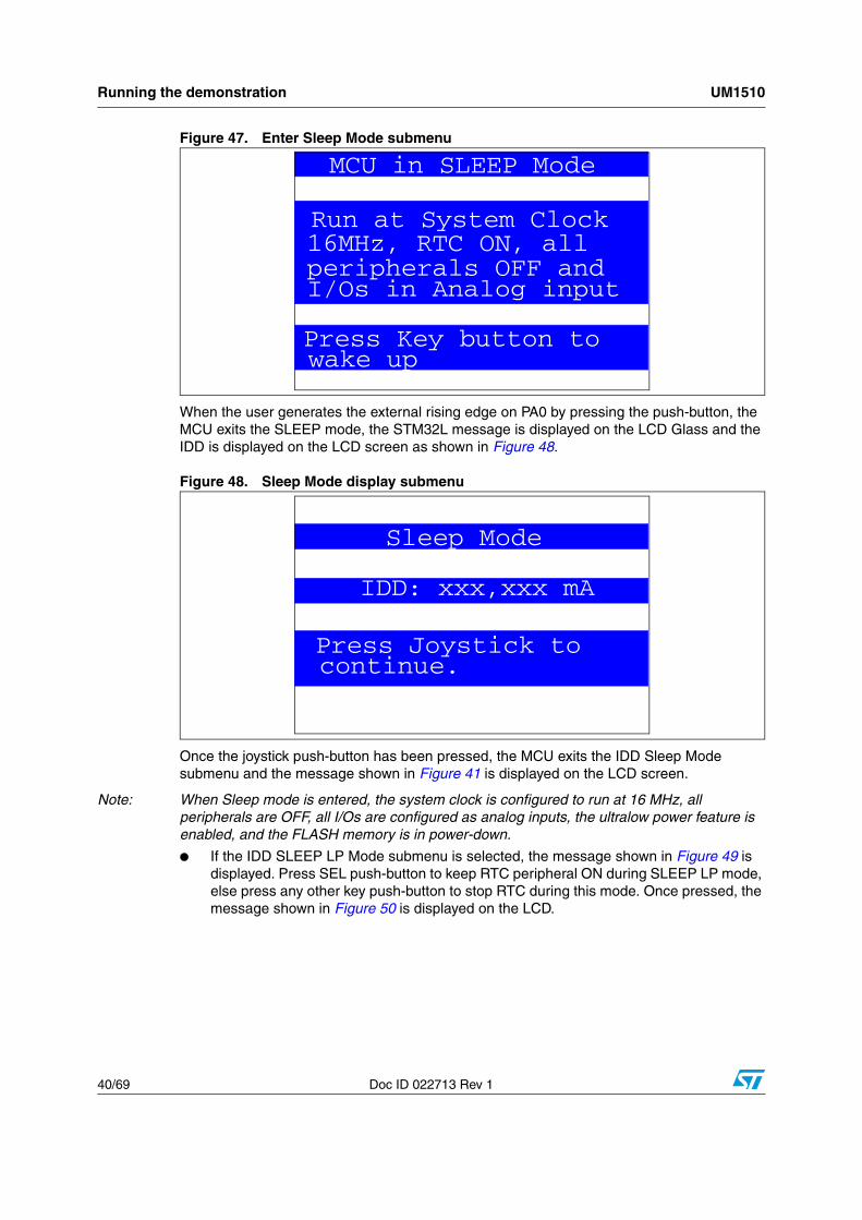
Figure 47. Enter Sleep Mode submenu
When the user generates the external rising edge on PA0 by pressing the push-button, the MCU exits the SLEEP mode, the STM32L message is displayed on the LCD Glass and the IDD is displayed on the LCD screen as shown in Figure 48.
Figure 48. Sleep Mode display submenu
Once the joystick push-button has been pressed, the MCU exits the IDD Sleep Mode submenu and the message shown in Figure 41 is displayed on the LCD screen.
Note: When Sleep mode is entered, the system clock is configured to run at 16 MHz, all peripherals are OFF, all I/Os are configured as analog inputs, the ultralow power feature is enabled, and the FLASH memory is in power-down.
● If the IDD SLEEP LP Mode submenu is selected, the message shown in Figure 49 is displayed. Press SEL push-button to keep RTC peripheral ON during SLEEP LP mode, else press any other key push-button to stop RTC during this mode. Once pressed, the message shown in Figure 50 is displayed on the LCD.
MCU in SLEEP Mode
16MHz, RTC ON, allperipherals OFF and
Run at System Clock
I/Os in Analog input
Press Key button towake up
Sleep Mode
Press Joystick tocontinue.
IDD: xxx,xxx mA
UM1510 Running the demonstration
Doc ID 022713 Rev 1 41/69
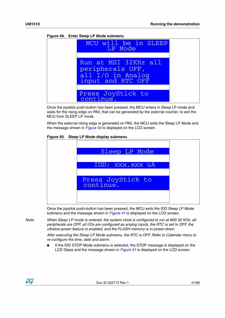
Figure 49. Enter Sleep LP Mode submenu
Once the joystick push-button has been pressed, the MCU enters in Sleep LP mode and waits for the rising edge on PA0, that can be generated by the external counter, to exit the MCU from SLEEP LP mode.
When the external rising edge is generated on PA0, the MCU exits the Sleep LP Mode and the message shown in Figure 50 is displayed on the LCD screen.
Figure 50. Sleep LP Mode display submenu
Once the joystick push-button has been pressed, the MCU exits the IDD Sleep LP Mode submenu and the message shown in Figure 41 is displayed on the LCD screen.
Note: When Sleep LP mode is entered, the system clock is configured to run at MSI 32 KHz, all peripherals are OFF, all I/Os are configured as analog inputs, the RTC is set to OFF, the ultralow power feature is enabled, and the FLASH memory is in power-down.
After executing the Sleep LP Mode submenu, the RTC is OFF. Refer to Calendar menu to re-configure the time, date and alarm.
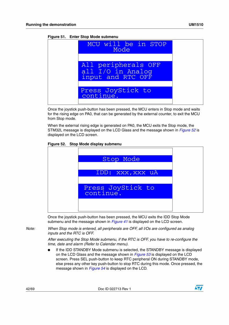
● If the IDD STOP Mode submenu is selected, the STOP message is displayed on the LCD Glass and the message shown in Figure 51 is displayed on the LCD screen.
MCU will be in SLEEP
peripherals OFF,all I/O in Analog
Run at MSI 32KHz all
input and RTC OFF
Press JoyStick tocontinue.
LP Mode
Sleep LP Mode
Press JoyStick tocontinue.
IDD: xxx,xxx uA
Running the demonstration UM1510
42/69 Doc ID 022713 Rev 1
Figure 51. Enter Stop Mode submenu
Once the joystick push-button has been pressed, the MCU enters in Stop mode and waits for the rising edge on PA0, that can be generated by the external counter, to exit the MCU from Stop mode.
When the external rising edge is generated on PA0, the MCU exits the Stop mode, the STM32L message is displayed on the LCD Glass and the message shown in Figure 52 is displayed on the LCD screen.
Figure 52. Stop Mode display submenu
Once the joystick push-button has been pressed, the MCU exits the IDD Stop Mode submenu and the message shown in Figure 41 is displayed on the LCD screen.
Note: When Stop mode is entered, all peripherals are OFF, all I/Os are configured as analog inputs and the RTC is OFF.
After executing the Stop Mode submenu, if the RTC is OFF, you have to re-configure the time, date and alarm (Refer to Calendar menu).
● If the IDD STANDBY Mode submenu is selected, the STANDBY message is displayed on the LCD Glass and the message shown in Figure 53 is displayed on the LCD screen. Press SEL push-button to keep RTC peripheral ON during STANDBY mode, else press any other key push-button to stop RTC during this mode. Once pressed, the message shown in Figure 54 is displayed on the LCD.
MCU will be in STOP
All peripherals OFFall I/O in Analoginput and RTC OFF
Press JoyStick tocontinue.
Mode
Stop Mode
Press JoyStick tocontinue.
IDD: xxx,xxx uA
UM1510 Running the demonstration
Doc ID 022713 Rev 1 43/69
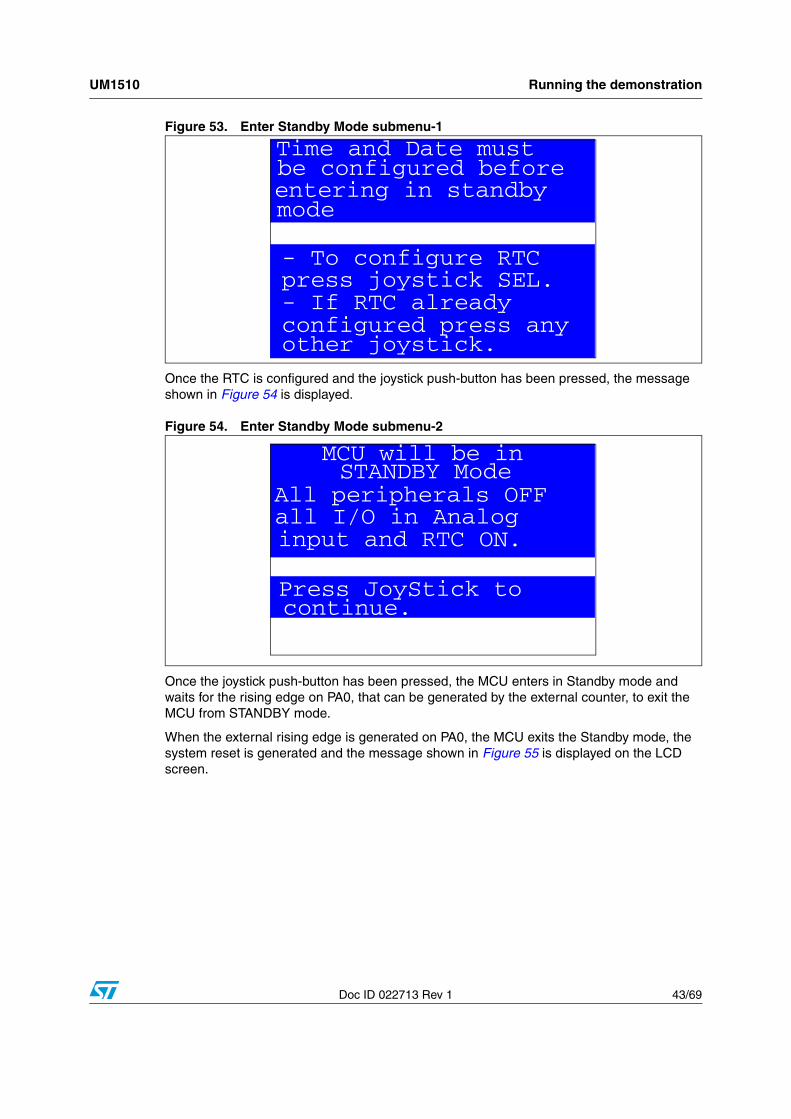
Figure 53. Enter Standby Mode submenu-1
Once the RTC is configured and the joystick push-button has been pressed, the message shown in Figure 54 is displayed.
Figure 54. Enter Standby Mode submenu-2
Once the joystick push-button has been pressed, the MCU enters in Standby mode and waits for the rising edge on PA0, that can be generated by the external counter, to exit the MCU from STANDBY mode.
When the external rising edge is generated on PA0, the MCU exits the Standby mode, the system reset is generated and the message shown in Figure 55 is displayed on the LCD screen.
Time and Date must
- If RTC already configured press anyother joystick.
be configured before
- To configure RTCpress joystick SEL.
entering in standby mode
MCU will be in STANDBY Mode
All peripherals OFFall I/O in Analog
Press JoyStick tocontinue.
input and RTC ON.
Running the demonstration UM1510
44/69 Doc ID 022713 Rev 1
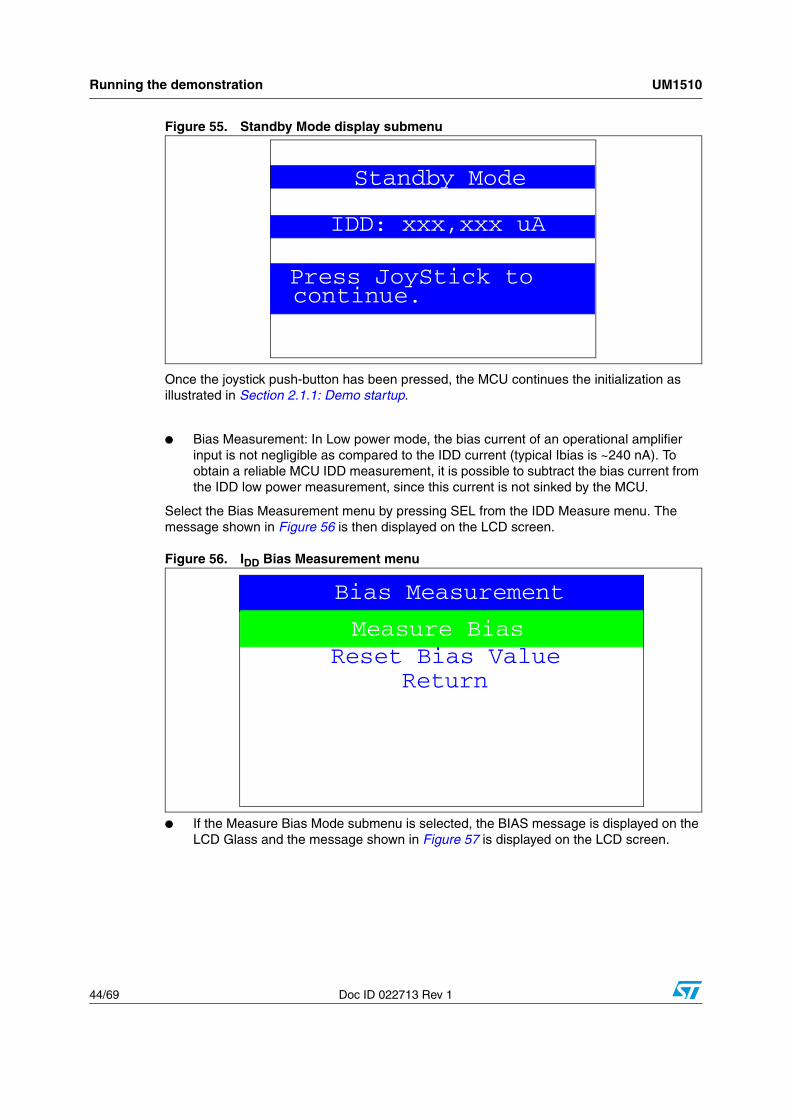
Figure 55. Standby Mode display submenu
Once the joystick push-button has been pressed, the MCU continues the initialization as illustrated in Section 2.1.1: Demo startup.
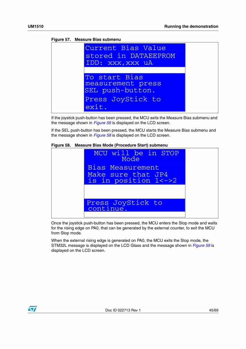
● Bias Measurement: In Low power mode, the bias current of an operational amplifier input is not negligible as compared to the IDD current (typical Ibias is ~240 nA). To obtain a reliable MCU IDD measurement, it is possible to subtract the bias current from the IDD low power measurement, since this current is not sinked by the MCU.
Select the Bias Measurement menu by pressing SEL from the IDD Measure menu. The message shown in Figure 56 is then displayed on the LCD screen.
Figure 56. IDD Bias Measurement menu
● If the Measure Bias Mode submenu is selected, the BIAS message is displayed on the LCD Glass and the message shown in Figure 57 is displayed on the LCD screen.
Standby Mode
Press JoyStick tocontinue.
IDD: xxx,xxx uA
Measure Bias
ReturnReset Bias Value
Bias Measurement
UM1510 Running the demonstration
Doc ID 022713 Rev 1 45/69
Figure 57. Measure Bias submenu
If the joystick push-button has been pressed, the MCU exits the Measure Bias submenu and the message shown in Figure 56 is displayed on the LCD screen.
If the SEL push-button has been pressed, the MCU starts the Measure Bias submenu and the message shown in Figure 58 is displayed on the LCD screen.
Figure 58. Measure Bias Mode (Procedure Start) submenu
Once the joystick push-button has been pressed, the MCU enters the Stop mode and waits for the rising edge on PA0, that can be generated by the external counter, to exit the MCU from Stop mode.
When the external rising edge is generated on PA0, the MCU exits the Stop mode, the STM32L message is displayed on the LCD Glass and the message shown in Figure 59 is displayed on the LCD screen.
Current Bias Value
IDD: xxx,xxx uAstored in DATAEEPROM
Current Bias Value
exit.
SEL push-button.
To start Biasmeasurement press
Press JoyStick to
MCU will be in STOP
Bias MeasurementMake sure that JP4is in position 1<->2
Press JoyStick tocontinue.
Mode
Running the demonstration UM1510
46/69 Doc ID 022713 Rev 1
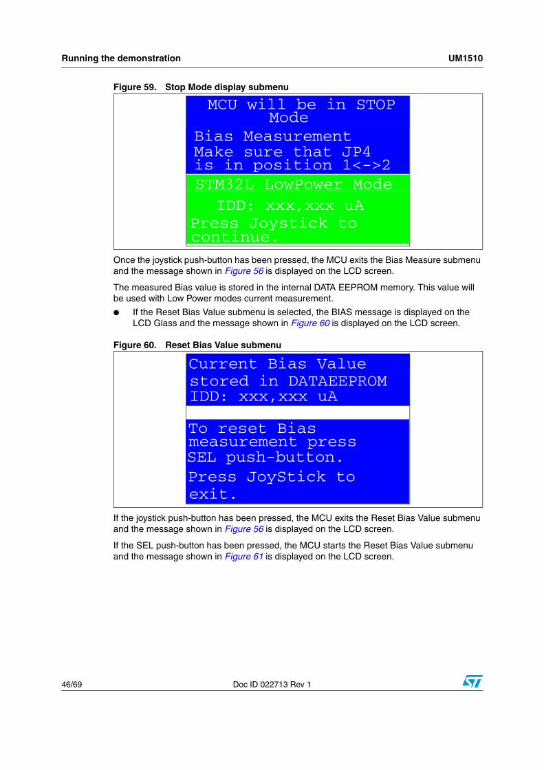
Figure 59. Stop Mode display submenu
Once the joystick push-button has been pressed, the MCU exits the Bias Measure submenu and the message shown in Figure 56 is displayed on the LCD screen.
The measured Bias value is stored in the internal DATA EEPROM memory. This value will be used with Low Power modes current measurement.
● If the Reset Bias Value submenu is selected, the BIAS message is displayed on the LCD Glass and the message shown in Figure 60 is displayed on the LCD screen.
Figure 60. Reset Bias Value submenu
If the joystick push-button has been pressed, the MCU exits the Reset Bias Value submenu and the message shown in Figure 56 is displayed on the LCD screen.
If the SEL push-button has been pressed, the MCU starts the Reset Bias Value submenu and the message shown in Figure 61 is displayed on the LCD screen.
Press Joystick tocontinue.
IDD: xxx,xxx uASTM32L LowPower Mode
MCU will be in STOP
Bias MeasurementMake sure that JP4is in position 1<->2
Mode
Current Bias Value
IDD: xxx,xxx uAstored in DATAEEPROM
Current Bias Value
exit.
SEL push-button.
To reset Biasmeasurement press
Press JoyStick to

UM1510 Running the demonstration
Doc ID 022713 Rev 1 47/69
Figure 61. Reset Bias Value (Procedure Start) submenu
Once the joystick push-button has been pressed, the MCU exits the Reset Bias Value submenu and the message shown in Figure 56 is displayed on the LCD screen.
2.4.7 Thermometer
The STM32L152ZD(T6) microcontroller has two embedded I2C peripherals that can be connected to any device supporting the I2C protocol including the System management bus (SMBus) mode. An STLM75 (or a compatible device) I2C temperature sensor is mounted on the STM32L152D-EVAL board and used to capture the external temperature (-55°C to +125°C).
When the Thermometer submenu is selected, the message shown in Figure 62 is displayed on the LCD.
Figure 62. Thermometer submenu selected
Once the Temperature submenu has been selected by pressing the SEL push-button, the temperature value is displayed in Celsius and Fahrenheit, as shown in Figure 63.
Press any key to return to the Thermometer submenu.
Bias MeasurementBias Value is resetto 0x0.
Press JoyStick tocontinue.
Thermometer
Return
Temperature
Running the demonstration UM1510
48/69 Doc ID 022713 Rev 1
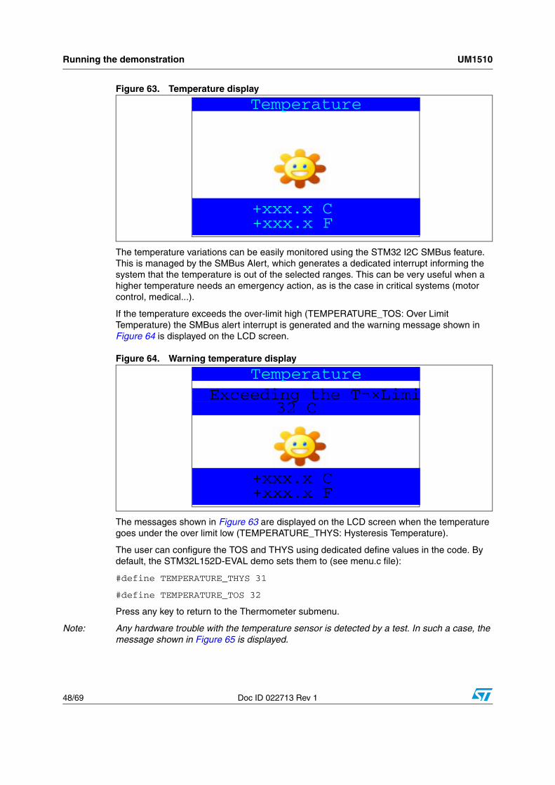
Figure 63. Temperature display
The temperature variations can be easily monitored using the STM32 I2C SMBus feature. This is managed by the SMBus Alert, which generates a dedicated interrupt informing the system that the temperature is out of the selected ranges. This can be very useful when a higher temperature needs an emergency action, as is the case in critical systems (motor control, medical...).
If the temperature exceeds the over-limit high (TEMPERATURE_TOS: Over Limit Temperature) the SMBus alert interrupt is generated and the warning message shown in Figure 64 is displayed on the LCD screen.
Figure 64. Warning temperature display
The messages shown in Figure 63 are displayed on the LCD screen when the temperature goes under the over limit low (TEMPERATURE_THYS: Hysteresis Temperature).
The user can configure the TOS and THYS using dedicated define values in the code. By default, the STM32L152D-EVAL demo sets them to (see menu.c file):
#define TEMPERATURE_THYS 31
#define TEMPERATURE_TOS 32
Press any key to return to the Thermometer submenu.
Note: Any hardware trouble with the temperature sensor is detected by a test. In such a case, the message shown in Figure 65 is displayed.
Temperature
+xxx.x C +xxx.x F
Temperature
+xxx.x C +xxx.x F
Exceeding the T¬×Limi 32 C
UM1510 Running the demonstration
Doc ID 022713 Rev 1 49/69
Figure 65. Temperature sensor error
2.4.8 USB Mass Storage Submenu
The STM32L152ZD(T6) microcontroller features a USB (universal serial bus) that provides a full-speed interface to a USB host PC.
The USB Mass Storage submenu is used to configure the USB interface for communication with the PC and to run the mass storage demo using an MSD card.
Figure 66. USB Mass Storage submenu
If the SEL push-button is pressed when Start is selected, the message shown in Figure 67 appears on the LCD screen until the cable is plugged in.
End of slide showClick to exit NO TSENSOR PresentExit: push joystick
USB Mass Storage
Return
Start
NAND Physical Format
Running the demonstration UM1510
50/69 Doc ID 022713 Rev 1
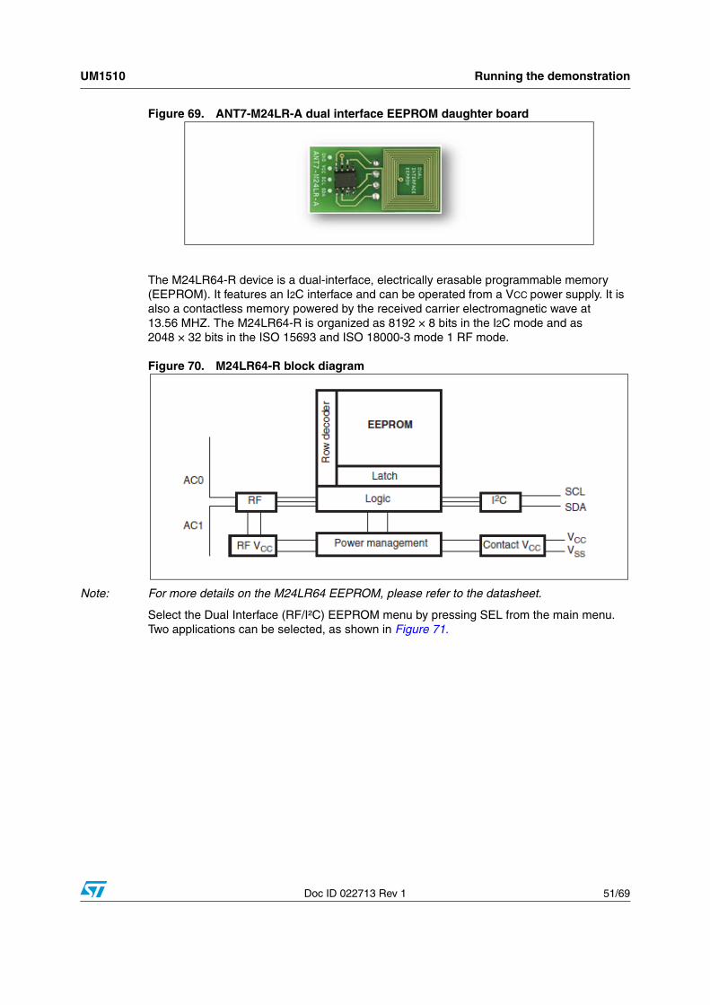
Figure 67. USB Mass Storage submenu selected
To return to the previous submenu, the user must connect a USB cable between the USB connector type B (CN15) and the PC. If the user connects a cable or presses any joystick push-button, the message shown in Figure 68 is displayed on the LCD.
Figure 68. USB cable connected
Once the cable has been connected, the PC recognizes the board as a mass storage device and consequently opens a window to show the contents of the MSD mounted on the STM32L152-EVAL board. The user can transfer files between the MSD and the PC.
2.4.9 Dual interface EEPROM (RF/I²C)
The STM32L152ZD(T6) microcontroller has two embedded I2C peripherals that can be connected to any device supporting the I2C protocol. An ANT7-M24LR-A dual interface RF EEPROM daughter board can be connected on CN12 to STM32L152D-EVAL via the I2C interface.
Note: For more details about the Dual Interface EEPROM daughter board, please refer to the ANT7-M24LR-A databrief.
Plug the USB Cable
Exit: Push joystick
To Stop Press SEL
UM1510 Running the demonstration
Doc ID 022713 Rev 1 51/69
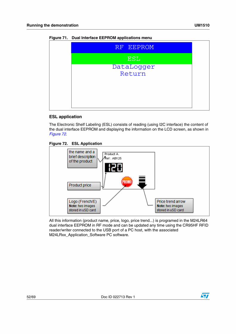
Figure 69. ANT7-M24LR-A dual interface EEPROM daughter board
The M24LR64-R device is a dual-interface, electrically erasable programmable memory (EEPROM). It features an I2C interface and can be operated from a VCC power supply. It is also a contactless memory powered by the received carrier electromagnetic wave at 13.56 MHZ. The M24LR64-R is organized as 8192 × 8 bits in the I2C mode and as 2048 × 32 bits in the ISO 15693 and ISO 18000-3 mode 1 RF mode.
Figure 70. M24LR64-R block diagram
Note: For more details on the M24LR64 EEPROM, please refer to the datasheet.
Select the Dual Interface (RF/I²C) EEPROM menu by pressing SEL from the main menu. Two applications can be selected, as shown in Figure 71.
Running the demonstration UM1510
52/69 Doc ID 022713 Rev 1
Figure 71. Dual Interface EEPROM applications menu
ESL application
The Electronic Shelf Labeling (ESL) consists of reading (using I2C interface) the content of the dual interface EEPROM and displaying the information on the LCD screen, as shown in Figure 72.
Figure 72. ESL Application
All this information (product name, price, logo, price trend...) is programed in the M24LR64 dual interface EEPROM in RF mode and can be updated any time using the CR95HF RFID reader/writer connected to the USB port of a PC host, with the associated M24LRxx_Application_Software PC software.
ESL
ReturnDataLogger
RF EEPROM
ESL
RF EERPOM
UM1510 Running the demonstration
Doc ID 022713 Rev 1 53/69
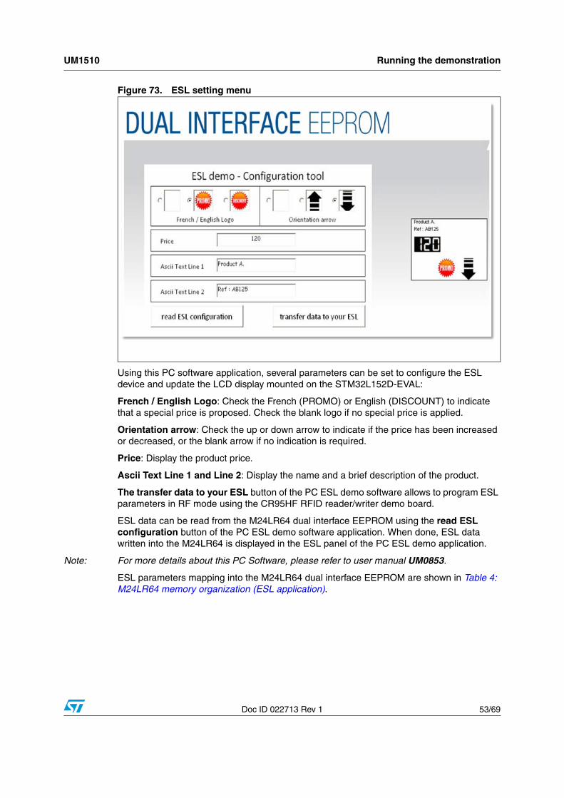
Figure 73. ESL setting menu
Using this PC software application, several parameters can be set to configure the ESL device and update the LCD display mounted on the STM32L152D-EVAL:
French / English Logo: Check the French (PROMO) or English (DISCOUNT) to indicate that a special price is proposed. Check the blank logo if no special price is applied.
Orientation arrow: Check the up or down arrow to indicate if the price has been increased or decreased, or the blank arrow if no indication is required.
Price: Display the product price.
Ascii Text Line 1 and Line 2: Display the name and a brief description of the product.
The transfer data to your ESL button of the PC ESL demo software allows to program ESL parameters in RF mode using the CR95HF RFID reader/writer demo board.
ESL data can be read from the M24LR64 dual interface EEPROM using the read ESL configuration button of the PC ESL demo software application. When done, ESL data written into the M24LR64 is displayed in the ESL panel of the PC ESL demo application.
Note: For more details about this PC Software, please refer to user manual UM0853.
ESL parameters mapping into the M24LR64 dual interface EEPROM are shown in Table 4: M24LR64 memory organization (ESL application).
ESL
RF EERPOM
Running the demonstration UM1510
54/69 Doc ID 022713 Rev 1
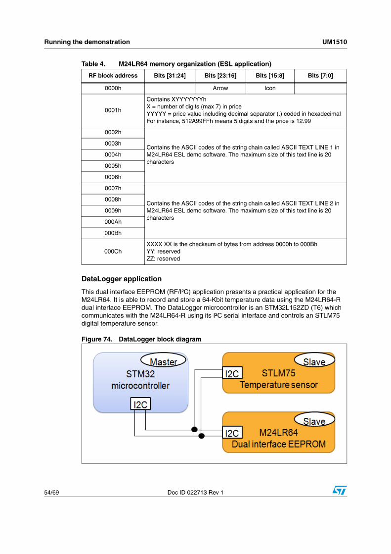
DataLogger application
This dual interface EEPROM (RF/I²C) application presents a practical application for the M24LR64. It is able to record and store a 64-Kbit temperature data using the M24LR64-R dual interface EEPROM. The DataLogger microcontroller is an STM32L152ZD (T6) which communicates with the M24LR64-R using its I²C serial interface and controls an STLM75 digital temperature sensor.
Figure 74. DataLogger block diagram
Table 4. M24LR64 memory organization (ESL application)
RF block address Bits [31:24] Bits [23:16] Bits [15:8] Bits [7:0]
0000h Arrow Icon
0001h
Contains XYYYYYYYhX = number of digits (max 7) in priceYYYYY = price value including decimal separator (.) coded in hexadecimalFor instance, 512A99FFh means 5 digits and the price is 12.99
0002h
Contains the ASCII codes of the string chain called ASCII TEXT LINE 1 in M24LR64 ESL demo software. The maximum size of this text line is 20 characters
0003h
0004h
0005h
0006h
0007h
Contains the ASCII codes of the string chain called ASCII TEXT LINE 2 in M24LR64 ESL demo software. The maximum size of this text line is 20 characters
0008h
0009h
000Ah
000Bh
000ChXXXX XX is the checksum of bytes from address 0000h to 000BhYY: reservedZZ: reserved
ESL
RF EERPOM
UM1510 Running the demonstration
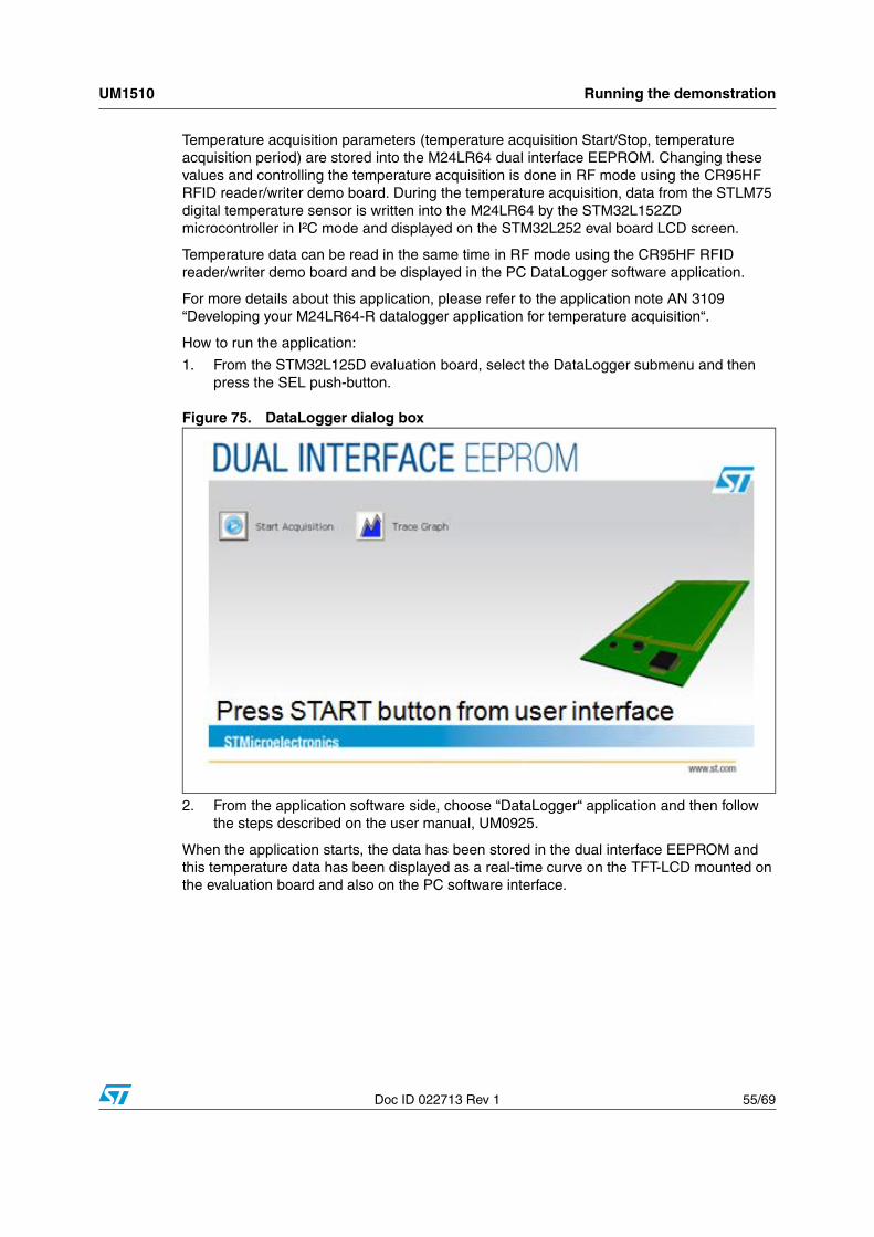
Doc ID 022713 Rev 1 55/69
Temperature acquisition parameters (temperature acquisition Start/Stop, temperature acquisition period) are stored into the M24LR64 dual interface EEPROM. Changing these values and controlling the temperature acquisition is done in RF mode using the CR95HF RFID reader/writer demo board. During the temperature acquisition, data from the STLM75 digital temperature sensor is written into the M24LR64 by the STM32L152ZD microcontroller in I²C mode and displayed on the STM32L252 eval board LCD screen.
Temperature data can be read in the same time in RF mode using the CR95HF RFID reader/writer demo board and be displayed in the PC DataLogger software application.
For more details about this application, please refer to the application note AN 3109 “Developing your M24LR64-R datalogger application for temperature acquisition“.
How to run the application:
1. From the STM32L125D evaluation board, select the DataLogger submenu and then press the SEL push-button.
Figure 75. DataLogger dialog box
2. From the application software side, choose “DataLogger“ application and then follow the steps described on the user manual, UM0925.
When the application starts, the data has been stored in the dual interface EEPROM and this temperature data has been displayed as a real-time curve on the TFT-LCD mounted on the evaluation board and also on the PC software interface.
Menu Navigation
Help
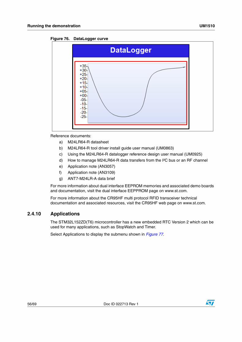
Running the demonstration UM1510
56/69 Doc ID 022713 Rev 1
Figure 76. DataLogger curve
Reference documents:
a) M24LR64-R datasheet
b) M24LR64-R tool driver install guide user manual (UM0863)
c) Using the M24LR64-R datalogger reference design user manual (UM0925)
d) How to manage M24LR64-R data transfers from the I²C bus or an RF channel
e) Application note (AN3057)
f) Application note (AN3109)
g) ANT7-M24LR-A data brief
For more information about dual interface EEPROM memories and associated demo boards and documentation, visit the dual interface EEPPROM page on www.st.com.
For more information about the CR95HF multi protocol RFID transceiver technical documentation and associated resources, visit the CR95HF web page on www.st.com.
2.4.10 Applications
The STM32L152ZD(T6) microcontroller has a new embedded RTC Version 2 which can be used for many applications, such as StopWatch and Timer.
Select Applications to display the submenu shown in Figure 77.
Menu Navigation
Help
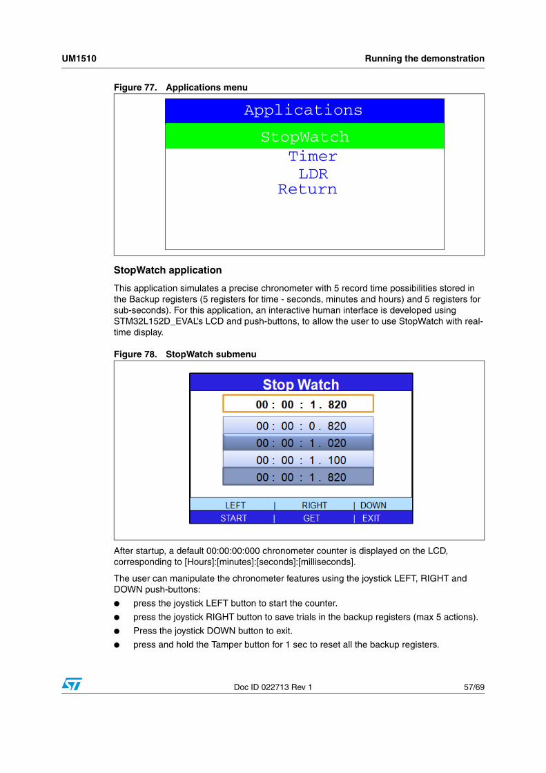
UM1510 Running the demonstration
Doc ID 022713 Rev 1 57/69
Figure 77. Applications menu
StopWatch application
This application simulates a precise chronometer with 5 record time possibilities stored in the Backup registers (5 registers for time - seconds, minutes and hours) and 5 registers for sub-seconds). For this application, an interactive human interface is developed using STM32L152D_EVAL’s LCD and push-buttons, to allow the user to use StopWatch with real-time display.
Figure 78. StopWatch submenu
After startup, a default 00:00:00:000 chronometer counter is displayed on the LCD, corresponding to [Hours]:[minutes]:[seconds]:[milliseconds].
The user can manipulate the chronometer features using the joystick LEFT, RIGHT and DOWN push-buttons:
● press the joystick LEFT button to start the counter.
● press the joystick RIGHT button to save trials in the backup registers (max 5 actions).
● Press the joystick DOWN button to exit.
● press and hold the Tamper button for 1 sec to reset all the backup registers.
StopWatch
LDRTimer
Applications
Return
StopWatch
Applications
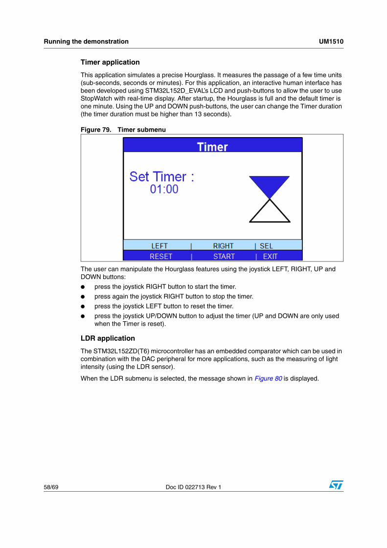
Running the demonstration UM1510
58/69 Doc ID 022713 Rev 1
Timer application
This application simulates a precise Hourglass. It measures the passage of a few time units (sub-seconds, seconds or minutes). For this application, an interactive human interface has been developed using STM32L152D_EVAL’s LCD and push-buttons to allow the user to use StopWatch with real-time display. After startup, the Hourglass is full and the default timer is one minute. Using the UP and DOWN push-buttons, the user can change the Timer duration (the timer duration must be higher than 13 seconds).
Figure 79. Timer submenu
The user can manipulate the Hourglass features using the joystick LEFT, RIGHT, UP and DOWN buttons:
● press the joystick RIGHT button to start the timer.
● press again the joystick RIGHT button to stop the timer.
● press the joystick LEFT button to reset the timer.
● press the joystick UP/DOWN button to adjust the timer (UP and DOWN are only used when the Timer is reset).
LDR application
The STM32L152ZD(T6) microcontroller has an embedded comparator which can be used in combination with the DAC peripheral for more applications, such as the measuring of light intensity (using the LDR sensor).
When the LDR submenu is selected, the message shown in Figure 80 is displayed.
StopWatch
Applications
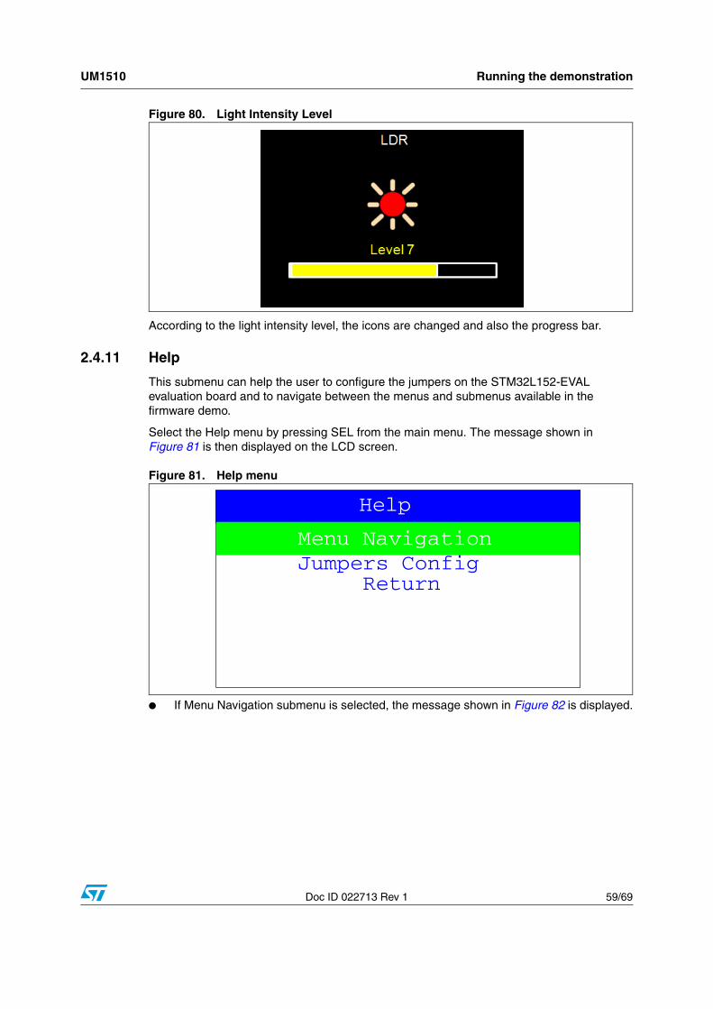
UM1510 Running the demonstration
Doc ID 022713 Rev 1 59/69
Figure 80. Light Intensity Level
According to the light intensity level, the icons are changed and also the progress bar.
2.4.11 Help
This submenu can help the user to configure the jumpers on the STM32L152-EVAL evaluation board and to navigate between the menus and submenus available in the firmware demo.
Select the Help menu by pressing SEL from the main menu. The message shown in Figure 81 is then displayed on the LCD screen.
Figure 81. Help menu
● If Menu Navigation submenu is selected, the message shown in Figure 82 is displayed.
Menu Navigation
ReturnJumpers Config
Help
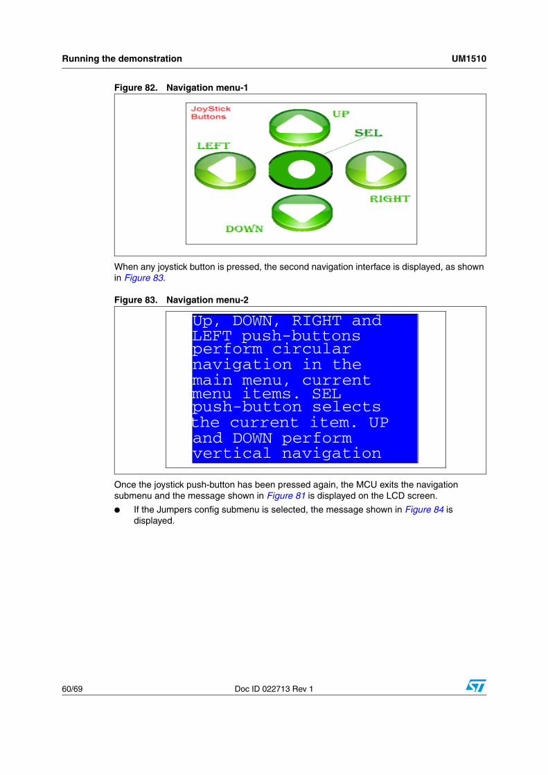
Running the demonstration UM1510
60/69 Doc ID 022713 Rev 1
Figure 82. Navigation menu-1
When any joystick button is pressed, the second navigation interface is displayed, as shown in Figure 83.
Figure 83. Navigation menu-2
Once the joystick push-button has been pressed again, the MCU exits the navigation submenu and the message shown in Figure 81 is displayed on the LCD screen.
● If the Jumpers config submenu is selected, the message shown in Figure 84 is displayed.
Up, DOWN, RIGHT and LEFT push-buttonsperform circularnavigation in themain menu, current
menu items. SELpush-button selectsthe current item. UPand DOWN performvertical navigation
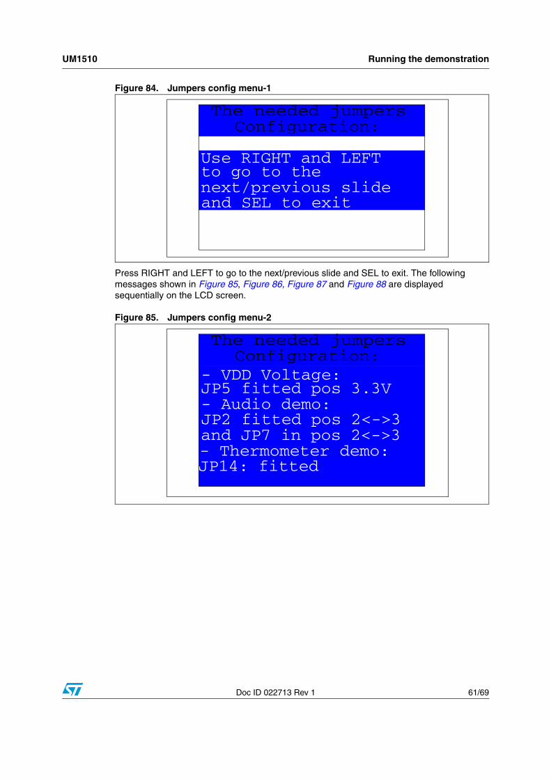
UM1510 Running the demonstration
Doc ID 022713 Rev 1 61/69
Figure 84. Jumpers config menu-1
Press RIGHT and LEFT to go to the next/previous slide and SEL to exit. The following messages shown in Figure 85, Figure 86, Figure 87 and Figure 88 are displayed sequentially on the LCD screen.
Figure 85. Jumpers config menu-2
Use RIGHT and LEFT
The needed jumpers Configuration:
to go to the next/previous slide and SEL to exit
- VDD Voltage:
The needed jumpers Configuration:
JP5 fitted pos 3.3V - Audio demo: JP2 fitted pos 2<->3 and JP7 in pos 2<->3- Thermometer demo:
JP14: fitted
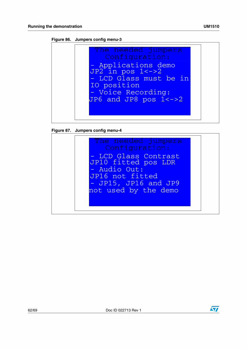
Running the demonstration UM1510
62/69 Doc ID 022713 Rev 1
Figure 86. Jumpers config menu-3
Figure 87. Jumpers config menu-4
- Applications demo
The needed jumpers Configuration:
JP2 in pos 1<->2 - LCD Glass must be in IO position - Voice Recording: JP6 and JP8 pos 1<->2
- LCD Glass Contrast
The needed jumpers Configuration:
JP10 fitted pos LDR - Audio Out: JP16 not fitted - JP15, JP16 and JP9 not used by the demo
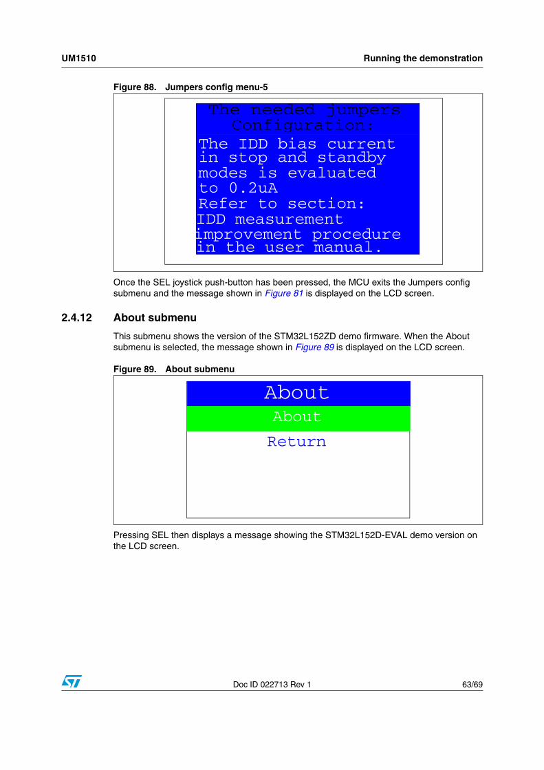
UM1510 Running the demonstration
Doc ID 022713 Rev 1 63/69
Figure 88. Jumpers config menu-5
Once the SEL joystick push-button has been pressed, the MCU exits the Jumpers config submenu and the message shown in Figure 81 is displayed on the LCD screen.
2.4.12 About submenu
This submenu shows the version of the STM32L152ZD demo firmware. When the About submenu is selected, the message shown in Figure 89 is displayed on the LCD screen.
Figure 89. About submenu
Pressing SEL then displays a message showing the STM32L152D-EVAL demo version on the LCD screen.
The IDD bias current
The needed jumpers Configuration:
in stop and standby modes is evaluated to 0.2uA Refer to section: IDD measurement improvement procedure in the user manual.
About
Return
About
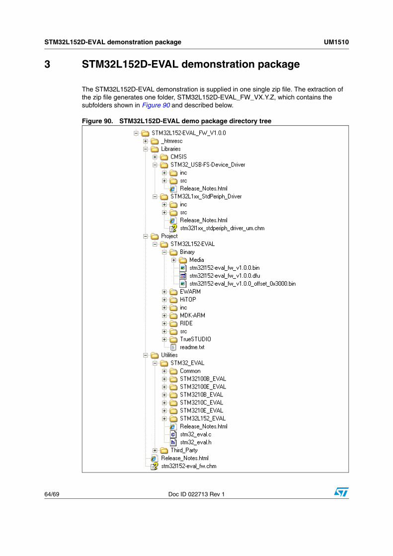
STM32L152D-EVAL demonstration package UM1510
64/69 Doc ID 022713 Rev 1
3 STM32L152D-EVAL demonstration package
The STM32L152D-EVAL demonstration is supplied in one single zip file. The extraction of the zip file generates one folder, STM32L152D-EVAL_FW_VX.Y.Z, which contains the subfolders shown in Figure 90 and described below.
Figure 90. STM32L152D-EVAL demo package directory tree

UM1510 STM32L152D-EVAL demonstration package
Doc ID 022713 Rev 1 65/69
1. Libraries: contains all the subdirectories and files that make up the core of the STM32L1xx Standard Peripheral library V1.0.0:
CMSIS
– CM3\CoreSupport: contains the Cortex-M3 files
– CM3\DeviceSupport\ST\STM32L15x: contains the STM32L1xx CMSIS layer files
STM32L1xx_Stdperiph_Driver
– inc subfolder contains the Standard Peripheral library header files
– src subfolder contains the Standard Peripheral library source files
STM32_USB-FS-Device_Driver
– inc subfolder contains the USB Full Speed Peripheral library header files
– src subfolder contains the USB Full Speed Peripheral library source files
2. Project
STM32L152D-EVAL
– Binary: contains the binary image of the demonstration that can be used to program the binary image to the internal Flash memory using IAP, plus the media files required to run the demo (Binary\Media)
– EWARM: contains preconfigured projects for the EWARM toolchain
– MDK-ARM: contains preconfigured projects for the MDK-ARM toolchain
– RIDE: contains preconfigured projects for the RIDE toolchain
– TrueSTUDIO: contains preconfigured projects for the Atollic toolchain
– HiTOP: contains preconfigured projects for the HiTOP toolchain
– inc: contains the Demo header files
– src: contains the Demo source files
3. Utilities
– STM32L152-EVAL: contains the LCD, and other STM32L152D-EVAL board-related drivers
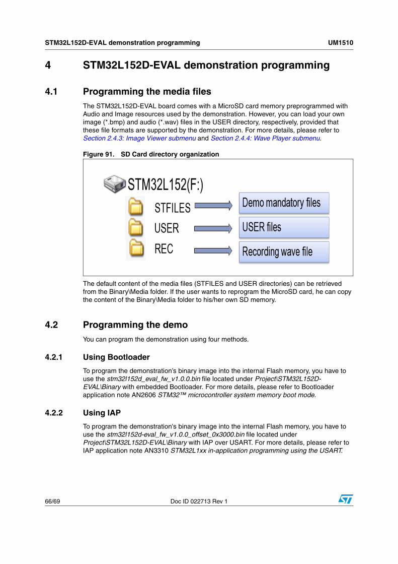
STM32L152D-EVAL demonstration programming UM1510
66/69 Doc ID 022713 Rev 1
4 STM32L152D-EVAL demonstration programming
4.1 Programming the media filesThe STM32L152D-EVAL board comes with a MicroSD card memory preprogrammed with Audio and Image resources used by the demonstration. However, you can load your own image (*.bmp) and audio (*.wav) files in the USER directory, respectively, provided that these file formats are supported by the demonstration. For more details, please refer to Section 2.4.3: Image Viewer submenu and Section 2.4.4: Wave Player submenu.
Figure 91. SD Card directory organization
The default content of the media files (STFILES and USER directories) can be retrieved from the Binary\Media folder. If the user wants to reprogram the MicroSD card, he can copy the content of the Binary\Media folder to his/her own SD memory.
4.2 Programming the demoYou can program the demonstration using four methods.
4.2.1 Using Bootloader
To program the demonstration’s binary image into the internal Flash memory, you have to use the stm32l152d_eval_fw_v1.0.0.bin file located under Project\STM32L152D-EVAL\Binary with embedded Bootloader. For more details, please refer to Bootloader application note AN2606 STM32™ microcontroller system memory boot mode.
4.2.2 Using IAP
To program the demonstration's binary image into the internal Flash memory, you have to use the stm32l152d-eval_fw_v1.0.0_offset_0x3000.bin file located under Project\STM32L152D-EVAL\Binary with IAP over USART. For more details, please refer to IAP application note AN3310 STM32L1xx in-application programming using the USART.

UM1510 STM32L152D-EVAL demonstration programming
Doc ID 022713 Rev 1 67/69
4.2.3 Using USB DFU
To program the demonstration's binary image into the internal Flash memory, you have to use the stm32l152d-eval_fw_v1.0.0.dfu file located under Project\STM32L152D-EVAL\Binary with USB DFU. For more details, please refer to user manual UM0424 STM32 USB-FS-Device development kit.
4.2.4 Using preconfigured projects
■ Select the folder corresponding to your preferred toolchain (MDK-ARM, EWARM, RIDE, TASKING or TrueSTUDIO).
■ Open the STM32L152D_EVAL project and rebuild all sources.
■ Load the project image through your debugger.
■ Restart the evaluation board (press B1: reset button).
Revision history UM1510
68/69 Doc ID 022713 Rev 1
5 Revision history
Table 5. Document revision history
Date Revision Changes
02-Apr-2012 1 Initial release.
UM1510
Doc ID 022713 Rev 1 69/69
Please Read Carefully:
Information in this document is provided solely in connection with ST products. STMicroelectronics NV and its subsidiaries (“ST”) reserve theright to make changes, corrections, modifications or improvements, to this document, and the products and services described herein at anytime, without notice.
All ST products are sold pursuant to ST’s terms and conditions of sale.
Purchasers are solely responsible for the choice, selection and use of the ST products and services described herein, and ST assumes noliability whatsoever relating to the choice, selection or use of the ST products and services described herein.
No license, express or implied, by estoppel or otherwise, to any intellectual property rights is granted under this document. If any part of thisdocument refers to any third party products or services it shall not be deemed a license grant by ST for the use of such third party productsor services, or any intellectual property contained therein or considered as a warranty covering the use in any manner whatsoever of suchthird party products or services or any intellectual property contained therein.
UNLESS OTHERWISE SET FORTH IN ST’S TERMS AND CONDITIONS OF SALE ST DISCLAIMS ANY EXPRESS OR IMPLIEDWARRANTY WITH RESPECT TO THE USE AND/OR SALE OF ST PRODUCTS INCLUDING WITHOUT LIMITATION IMPLIEDWARRANTIES OF MERCHANTABILITY, FITNESS FOR A PARTICULAR PURPOSE (AND THEIR EQUIVALENTS UNDER THE LAWSOF ANY JURISDICTION), OR INFRINGEMENT OF ANY PATENT, COPYRIGHT OR OTHER INTELLECTUAL PROPERTY RIGHT.
UNLESS EXPRESSLY APPROVED IN WRITING BY TWO AUTHORIZED ST REPRESENTATIVES, ST PRODUCTS ARE NOTRECOMMENDED, AUTHORIZED OR WARRANTED FOR USE IN MILITARY, AIR CRAFT, SPACE, LIFE SAVING, OR LIFE SUSTAININGAPPLICATIONS, NOR IN PRODUCTS OR SYSTEMS WHERE FAILURE OR MALFUNCTION MAY RESULT IN PERSONAL INJURY,DEATH, OR SEVERE PROPERTY OR ENVIRONMENTAL DAMAGE. ST PRODUCTS WHICH ARE NOT SPECIFIED AS "AUTOMOTIVEGRADE" MAY ONLY BE USED IN AUTOMOTIVE APPLICATIONS AT USER’S OWN RISK.
Resale of ST products with provisions different from the statements and/or technical features set forth in this document shall immediately voidany warranty granted by ST for the ST product or service described herein and shall not create or extend in any manner whatsoever, anyliability of ST.
ST and the ST logo are trademarks or registered trademarks of ST in various countries.
Information in this document supersedes and replaces all information previously supplied.
The ST logo is a registered trademark of STMicroelectronics. All other names are the property of their respective owners.
© 2012 STMicroelectronics - All rights reserved
STMicroelectronics group of companies
Australia - Belgium - Brazil - Canada - China - Czech Republic - Finland - France - Germany - Hong Kong - India - Israel - Italy - Japan - Malaysia - Malta - Morocco - Philippines - Singapore - Spain - Sweden - Switzerland - United Kingdom - United States of America
www.st.com