Embed Size (px)
Citation preview
September 2015 DocID028226 Rev 1 1/48
1
UM1937User manual
STM32CubeL4 demonstration firmware for STM32L476G-EVAL board
Introduction
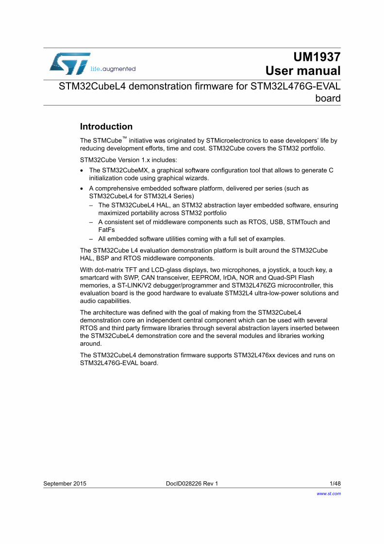
The STMCube™ initiative was originated by STMicroelectronics to ease developers’ life by reducing development efforts, time and cost. STM32Cube covers the STM32 portfolio.
STM32Cube Version 1.x includes:
• The STM32CubeMX, a graphical software configuration tool that allows to generate C initialization code using graphical wizards.
• A comprehensive embedded software platform, delivered per series (such as STM32CubeL4 for STM32L4 Series)
– The STM32CubeL4 HAL, an STM32 abstraction layer embedded software, ensuring maximized portability across STM32 portfolio
– A consistent set of middleware components such as RTOS, USB, STMTouch and FatFs
– All embedded software utilities coming with a full set of examples.
The STM32Cube L4 evaluation demonstration platform is built around the STM32Cube HAL, BSP and RTOS middleware components.
With dot-matrix TFT and LCD-glass displays, two microphones, a joystick, a touch key, a smartcard with SWP, CAN transceiver, EEPROM, IrDA, NOR and Quad-SPI Flash memories, a ST-LINK/V2 debugger/programmer and STM32L476ZG microcontroller, this evaluation board is the good hardware to evaluate STM32L4 ultra-low-power solutions and audio capabilities.
The architecture was defined with the goal of making from the STM32CubeL4 demonstration core an independent central component which can be used with several RTOS and third party firmware libraries through several abstraction layers inserted between the STM32CubeL4 demonstration core and the several modules and libraries working around.
The STM32CubeL4 demonstration firmware supports STM32L476xx devices and runs on STM32L476G-EVAL board.
www.st.com
Contents UM1937
2/48 DocID028226 Rev 1
Contents
1 STM32Cube overview . . . . . . . . . . . . . . . . . . . . . . . . . . . . . . . . . . . . . . . . 6
2 Getting started with demonstration . . . . . . . . . . . . . . . . . . . . . . . . . . . . . 7
2.1 Hardware requirements . . . . . . . . . . . . . . . . . . . . . . . . . . . . . . . . . . . . . . . 7
2.1.1 Hardware configuration to run the demonstration firmware . . . . . . . . . . . 7
3 Demonstration firmware package . . . . . . . . . . . . . . . . . . . . . . . . . . . . . . 9
3.1 Demonstration repository . . . . . . . . . . . . . . . . . . . . . . . . . . . . . . . . . . . . . . 9
3.2 Demonstration architecture overview . . . . . . . . . . . . . . . . . . . . . . . . . . . . 10
3.3 STM32L476G-EVAL board BSP . . . . . . . . . . . . . . . . . . . . . . . . . . . . . . . .11
4 Demonstration functional description . . . . . . . . . . . . . . . . . . . . . . . . . 13
4.1 Kernel . . . . . . . . . . . . . . . . . . . . . . . . . . . . . . . . . . . . . . . . . . . . . . . . . . . 13
4.1.1 CPU usage . . . . . . . . . . . . . . . . . . . . . . . . . . . . . . . . . . . . . . . . . . . . . . 14
4.1.2 Kernel log . . . . . . . . . . . . . . . . . . . . . . . . . . . . . . . . . . . . . . . . . . . . . . . . 14
4.1.3 Process viewer . . . . . . . . . . . . . . . . . . . . . . . . . . . . . . . . . . . . . . . . . . . 14
4.2 Modules . . . . . . . . . . . . . . . . . . . . . . . . . . . . . . . . . . . . . . . . . . . . . . . . . . 15
4.2.1 System . . . . . . . . . . . . . . . . . . . . . . . . . . . . . . . . . . . . . . . . . . . . . . . . . . 15
4.2.2 Audio player . . . . . . . . . . . . . . . . . . . . . . . . . . . . . . . . . . . . . . . . . . . . . . 16
4.2.3 Audio recorder . . . . . . . . . . . . . . . . . . . . . . . . . . . . . . . . . . . . . . . . . . . . 20
4.2.4 File Browser . . . . . . . . . . . . . . . . . . . . . . . . . . . . . . . . . . . . . . . . . . . . . . 21
4.2.5 Image viewer . . . . . . . . . . . . . . . . . . . . . . . . . . . . . . . . . . . . . . . . . . . . . 22
4.2.6 Idd . . . . . . . . . . . . . . . . . . . . . . . . . . . . . . . . . . . . . . . . . . . . . . . . . . . . . 24
4.2.7 USB mass storage device . . . . . . . . . . . . . . . . . . . . . . . . . . . . . . . . . . . 25
4.2.8 Game . . . . . . . . . . . . . . . . . . . . . . . . . . . . . . . . . . . . . . . . . . . . . . . . . . . 28
5 Demonstration firmware settings . . . . . . . . . . . . . . . . . . . . . . . . . . . . . 28
5.1 Clock control . . . . . . . . . . . . . . . . . . . . . . . . . . . . . . . . . . . . . . . . . . . . . . . 28
5.2 Peripherals . . . . . . . . . . . . . . . . . . . . . . . . . . . . . . . . . . . . . . . . . . . . . . . . 28
5.3 Interrupts / Wakeup pins . . . . . . . . . . . . . . . . . . . . . . . . . . . . . . . . . . . . . 29
5.4 System memory configuration . . . . . . . . . . . . . . . . . . . . . . . . . . . . . . . . . 30
5.5 FreeRTOS resources . . . . . . . . . . . . . . . . . . . . . . . . . . . . . . . . . . . . . . . 30
5.5.1 Tasks . . . . . . . . . . . . . . . . . . . . . . . . . . . . . . . . . . . . . . . . . . . . . . . . . . . 30
DocID028226 Rev 1 3/48
UM1937 Contents
3
5.5.2 Message queues . . . . . . . . . . . . . . . . . . . . . . . . . . . . . . . . . . . . . . . . . . 31
5.5.3 Heap . . . . . . . . . . . . . . . . . . . . . . . . . . . . . . . . . . . . . . . . . . . . . . . . . . . 31
5.6 Programming firmware application . . . . . . . . . . . . . . . . . . . . . . . . . . . . . 31
5.6.1 Using binary file . . . . . . . . . . . . . . . . . . . . . . . . . . . . . . . . . . . . . . . . . . . 32
5.6.2 Using pre-configured projects . . . . . . . . . . . . . . . . . . . . . . . . . . . . . . . . 32
6 Kernel description . . . . . . . . . . . . . . . . . . . . . . . . . . . . . . . . . . . . . . . . . . 32
6.1 Overview . . . . . . . . . . . . . . . . . . . . . . . . . . . . . . . . . . . . . . . . . . . . . . . . . 32
6.2 Kernel core files . . . . . . . . . . . . . . . . . . . . . . . . . . . . . . . . . . . . . . . . . . . . 32
6.3 Kernel initialization . . . . . . . . . . . . . . . . . . . . . . . . . . . . . . . . . . . . . . . . . . 33
6.4 Kernel processes and tasks . . . . . . . . . . . . . . . . . . . . . . . . . . . . . . . . . . 34
6.5 Kernel graphical aspect . . . . . . . . . . . . . . . . . . . . . . . . . . . . . . . . . . . . . . 35
6.6 Kernel menu management . . . . . . . . . . . . . . . . . . . . . . . . . . . . . . . . . . . . 35
6.7 Modules manager . . . . . . . . . . . . . . . . . . . . . . . . . . . . . . . . . . . . . . . . . . . 36
6.8 Backup and settings configuration . . . . . . . . . . . . . . . . . . . . . . . . . . . . . . 38
6.9 Storage units . . . . . . . . . . . . . . . . . . . . . . . . . . . . . . . . . . . . . . . . . . . . . . 38
7 How to create a new module . . . . . . . . . . . . . . . . . . . . . . . . . . . . . . . . . 40
7.1 Creating the graphical aspect . . . . . . . . . . . . . . . . . . . . . . . . . . . . . . . . . . 40
7.2 Graphics customization . . . . . . . . . . . . . . . . . . . . . . . . . . . . . . . . . . . . . . 41
7.3 Module implementation . . . . . . . . . . . . . . . . . . . . . . . . . . . . . . . . . . . . . . 42
7.4 Adding a module to the main desktop . . . . . . . . . . . . . . . . . . . . . . . . . . . 43
7.5 Module direct open . . . . . . . . . . . . . . . . . . . . . . . . . . . . . . . . . . . . . . . . . . 43
8 Demonstration customization and configuration . . . . . . . . . . . . . . . . 44
8.1 LCD configuration . . . . . . . . . . . . . . . . . . . . . . . . . . . . . . . . . . . . . . . . . . . 44
8.2 Layers management . . . . . . . . . . . . . . . . . . . . . . . . . . . . . . . . . . . . . . . . . 45
8.3 Touchscreen calibration . . . . . . . . . . . . . . . . . . . . . . . . . . . . . . . . . . . . . . 45
9 Revision history . . . . . . . . . . . . . . . . . . . . . . . . . . . . . . . . . . . . . . . . . . . 47
List of tables UM1937
4/48 DocID028226 Rev 1
List of tables
Table 1. Jumper configurations . . . . . . . . . . . . . . . . . . . . . . . . . . . . . . . . . . . . . . . . . . . . . . . . . . . . . 7Table 2. Data structure for the audio player module. . . . . . . . . . . . . . . . . . . . . . . . . . . . . . . . . . . . . 18Table 3. Audio player control description . . . . . . . . . . . . . . . . . . . . . . . . . . . . . . . . . . . . . . . . . . . . . 19Table 4. Image viewer control description . . . . . . . . . . . . . . . . . . . . . . . . . . . . . . . . . . . . . . . . . . . . 24Table 5. USB mass storage control description . . . . . . . . . . . . . . . . . . . . . . . . . . . . . . . . . . . . . . . . 27Table 6. Used peripherals. . . . . . . . . . . . . . . . . . . . . . . . . . . . . . . . . . . . . . . . . . . . . . . . . . . . . . . . . 28Table 7. Demonstration firmware interrupts . . . . . . . . . . . . . . . . . . . . . . . . . . . . . . . . . . . . . . . . . . . 29Table 8. Memory configurations . . . . . . . . . . . . . . . . . . . . . . . . . . . . . . . . . . . . . . . . . . . . . . . . . . . . 30Table 9. Task descriptions . . . . . . . . . . . . . . . . . . . . . . . . . . . . . . . . . . . . . . . . . . . . . . . . . . . . . . . . 30Table 10. Message queue descriptions . . . . . . . . . . . . . . . . . . . . . . . . . . . . . . . . . . . . . . . . . . . . . . . 31Table 11. Application Heap usage . . . . . . . . . . . . . . . . . . . . . . . . . . . . . . . . . . . . . . . . . . . . . . . . . . . 31Table 12. Kernel core file description . . . . . . . . . . . . . . . . . . . . . . . . . . . . . . . . . . . . . . . . . . . . . . . . . 32Table 13. File system interface functions descriptions . . . . . . . . . . . . . . . . . . . . . . . . . . . . . . . . . . . . 38Table 14. API functions descriptions . . . . . . . . . . . . . . . . . . . . . . . . . . . . . . . . . . . . . . . . . . . . . . . . . 39Table 15. Document revision history . . . . . . . . . . . . . . . . . . . . . . . . . . . . . . . . . . . . . . . . . . . . . . . . . 47
DocID028226 Rev 1 5/48
UM1937 List of figures
5
List of figures
Figure 1. STM32Cube block diagram . . . . . . . . . . . . . . . . . . . . . . . . . . . . . . . . . . . . . . . . . . . . . . . . . 6Figure 2. STM32L476G-EVAL board. . . . . . . . . . . . . . . . . . . . . . . . . . . . . . . . . . . . . . . . . . . . . . . . . . 8Figure 3. Folder structure. . . . . . . . . . . . . . . . . . . . . . . . . . . . . . . . . . . . . . . . . . . . . . . . . . . . . . . . . . . 9Figure 4. Demonstration architecture overview . . . . . . . . . . . . . . . . . . . . . . . . . . . . . . . . . . . . . . . . . 10Figure 5. EVAL BSP structure . . . . . . . . . . . . . . . . . . . . . . . . . . . . . . . . . . . . . . . . . . . . . . . . . . . . . . 11Figure 6. Main desktop (Part I) . . . . . . . . . . . . . . . . . . . . . . . . . . . . . . . . . . . . . . . . . . . . . . . . . . . . . 13Figure 7. Main desktop (Part II) . . . . . . . . . . . . . . . . . . . . . . . . . . . . . . . . . . . . . . . . . . . . . . . . . . . . 13Figure 8. CPU usage . . . . . . . . . . . . . . . . . . . . . . . . . . . . . . . . . . . . . . . . . . . . . . . . . . . . . . . . . . . . . 14Figure 9. Process viewer . . . . . . . . . . . . . . . . . . . . . . . . . . . . . . . . . . . . . . . . . . . . . . . . . . . . . . . . . . 14Figure 10. System information . . . . . . . . . . . . . . . . . . . . . . . . . . . . . . . . . . . . . . . . . . . . . . . . . . . . . . . 15Figure 11. Clock settings . . . . . . . . . . . . . . . . . . . . . . . . . . . . . . . . . . . . . . . . . . . . . . . . . . . . . . . . . . . 15Figure 12. Audio player module . . . . . . . . . . . . . . . . . . . . . . . . . . . . . . . . . . . . . . . . . . . . . . . . . . . . . . 16Figure 13. Audio player module architecture . . . . . . . . . . . . . . . . . . . . . . . . . . . . . . . . . . . . . . . . . . . . 17Figure 14. Audio recorder module . . . . . . . . . . . . . . . . . . . . . . . . . . . . . . . . . . . . . . . . . . . . . . . . . . . . 20Figure 15. Audio recorder with direct open for audio playback or file management . . . . . . . . . . . . . . 20Figure 16. Audio recorder module architecture . . . . . . . . . . . . . . . . . . . . . . . . . . . . . . . . . . . . . . . . . . 21Figure 17. File Browser architecture . . . . . . . . . . . . . . . . . . . . . . . . . . . . . . . . . . . . . . . . . . . . . . . . . . 22Figure 18. Image viewer architecture. . . . . . . . . . . . . . . . . . . . . . . . . . . . . . . . . . . . . . . . . . . . . . . . . . 23Figure 19. Idd module . . . . . . . . . . . . . . . . . . . . . . . . . . . . . . . . . . . . . . . . . . . . . . . . . . . . . . . . . . . . . 25Figure 20. USB device module architecture . . . . . . . . . . . . . . . . . . . . . . . . . . . . . . . . . . . . . . . . . . . . 26Figure 21. USB device module . . . . . . . . . . . . . . . . . . . . . . . . . . . . . . . . . . . . . . . . . . . . . . . . . . . . . . 26Figure 22. Game module application . . . . . . . . . . . . . . . . . . . . . . . . . . . . . . . . . . . . . . . . . . . . . . . . . . 28Figure 23. File system architecture . . . . . . . . . . . . . . . . . . . . . . . . . . . . . . . . . . . . . . . . . . . . . . . . . . . 40Figure 24. The GUIBuilder overview . . . . . . . . . . . . . . . . . . . . . . . . . . . . . . . . . . . . . . . . . . . . . . . . . . 41Figure 25. Graphics customization . . . . . . . . . . . . . . . . . . . . . . . . . . . . . . . . . . . . . . . . . . . . . . . . . . . 42Figure 26. Direct open from file browser . . . . . . . . . . . . . . . . . . . . . . . . . . . . . . . . . . . . . . . . . . . . . . . 43Figure 27. LCDConf location . . . . . . . . . . . . . . . . . . . . . . . . . . . . . . . . . . . . . . . . . . . . . . . . . . . . . . . . 44Figure 28. k_calibration.c location . . . . . . . . . . . . . . . . . . . . . . . . . . . . . . . . . . . . . . . . . . . . . . . . . . . . 45Figure 29. Calibration steps . . . . . . . . . . . . . . . . . . . . . . . . . . . . . . . . . . . . . . . . . . . . . . . . . . . . . . . . . 46
STM32Cube overview UM1937
6/48 DocID028226 Rev 1
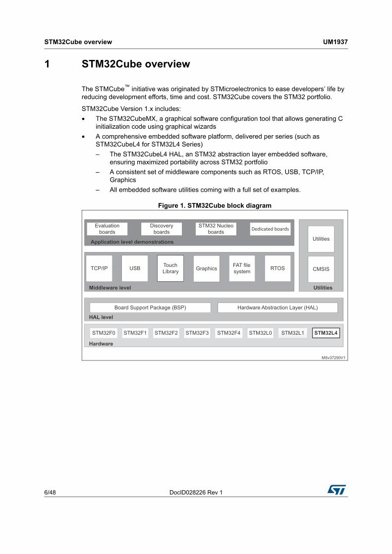
1 STM32Cube overview
The STMCube™ initiative was originated by STMicroelectronics to ease developers’ life by reducing development efforts, time and cost. STM32Cube covers the STM32 portfolio.
STM32Cube Version 1.x includes:
• The STM32CubeMX, a graphical software configuration tool that allows generating C initialization code using graphical wizards
• A comprehensive embedded software platform, delivered per series (such as STM32CubeL4 for STM32L4 Series)
– The STM32CubeL4 HAL, an STM32 abstraction layer embedded software, ensuring maximized portability across STM32 portfolio
– A consistent set of middleware components such as RTOS, USB, TCP/IP, Graphics
– All embedded software utilities coming with a full set of examples.
Figure 1. STM32Cube block diagram
DocID028226 Rev 1 7/48
UM1937 Getting started with demonstration
47
2 Getting started with demonstration
2.1 Hardware requirements
The hardware requirements to start the demonstration application are as follows:
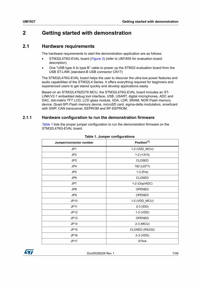
• STM32L476G-EVAL board (Figure 2) (refer to UM1855 for evaluation board description)
• One “USB type A to type B” cable to power up the STM32 evaluation board from the USB ST-LINK (standard-B USB connector CN17)
The STM32L476G-EVAL board helps the user to discover the ultra-low-power features and audio capabilities of the STM32L4 Series. It offers everything required for beginners and experienced users to get stared quickly and develop applications easily.
Based on an STM32L476ZGT6 MCU, the STM32L476G-EVAL board includes an ST-LINK/V2-1 embedded debug tool interface, USB, USART, digital microphones, ADC and DAC, dot-matrix TFT LCD, LCD glass module, IrDA, LDR, SRAM, NOR Flash memory device, Quad-SPI Flash memory device, microSD card, sigma-delta modulators, smartcard with SWP, CAN transceiver, EEPROM and RF-EEPROM.
2.1.1 Hardware configuration to run the demonstration firmware
Table 1 lists the proper jumper configuration to run the demonstration firmware on the STM32L476G-EVAL board.
Table 1. Jumper configurations
Jumper/connector number Position(1)
JP1 1-2 (VDD_MCU)
JP2 1-2 (+3V3)
JP3 CLOSED
JP4 162 (LEFT)
JP5 1-2 (Pot)
JP6 CLOSED
JP7 1-2 (Oop/ADC)
JP8 OPENED
JP9 OPENED
JP10 1-2 (VDD_MCU)
JP11 2-3 (IDD)
JP12 1-2 (VDD)
JP13 OPENED
JP14 2-3 (MCU)
JP15 CLOSED (RS232)
JP16 2-3 (VDD)
JP17 STlink
Getting started with demonstration UM1937
8/48 DocID028226 Rev 1
LCD glass must be mounted in IO position.
Please refer to UM1855 evaluation board with STM32L476ZGT6 MCU for a complete description of jumper settings.
Figure 2. STM32L476G-EVAL board
JP18 OPENED
JP19 CLOSED
CN10 CLOSED (ADC VREF)
1. Position 1 corresponds to jumper side with a dot marking.
Table 1. Jumper configurations (continued)
Jumper/connector number Position(1)
DocID028226 Rev 1 9/48
UM1937 Demonstration firmware package
47
3 Demonstration firmware package
3.1 Demonstration repository
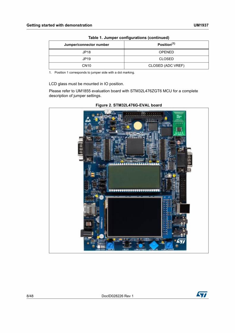
The STM32CubeL4 demonstration firmware for STM32L476G-EVAL board is provided within the STM32CubeL4 firmware package as shown in Figure 3.
Figure 3. Folder structure
The demonstration sources are located in the project folder of the STM32Cube package for each supported board. The sources are divided into five groups described as follows:
• Binary: demonstration binary file in Hex format
• Config: all middleware components and HAL configuration files
• Core: contains the kernel files
• Modules: contains the sources files for main application top level and the application modules
• Project settings: a folder per tool chain containing the project settings and the linker files.
Demonstration firmware package UM1937
10/48 DocID028226 Rev 1
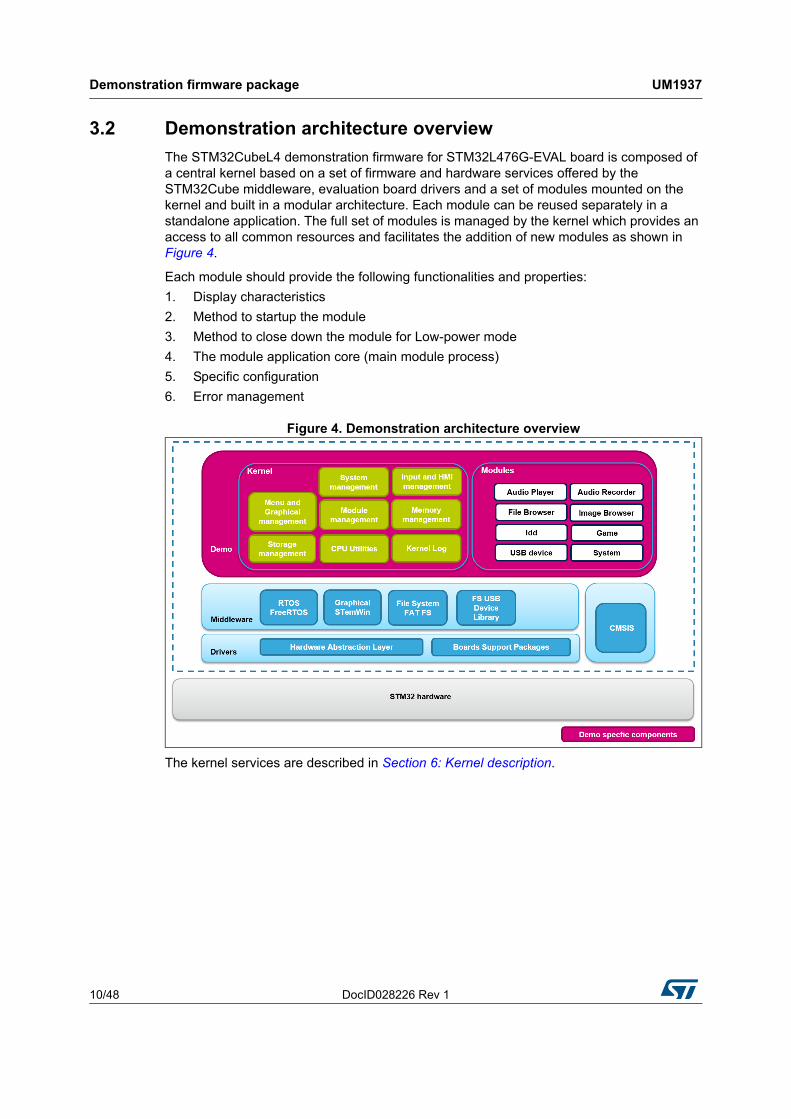
3.2 Demonstration architecture overview
The STM32CubeL4 demonstration firmware for STM32L476G-EVAL board is composed of a central kernel based on a set of firmware and hardware services offered by the STM32Cube middleware, evaluation board drivers and a set of modules mounted on the kernel and built in a modular architecture. Each module can be reused separately in a standalone application. The full set of modules is managed by the kernel which provides an access to all common resources and facilitates the addition of new modules as shown in Figure 4.
Each module should provide the following functionalities and properties:
1. Display characteristics
2. Method to startup the module
3. Method to close down the module for Low-power mode
4. The module application core (main module process)
5. Specific configuration
6. Error management
Figure 4. Demonstration architecture overview
The kernel services are described in Section 6: Kernel description.

DocID028226 Rev 1 11/48
UM1937 Demonstration firmware package
47
3.3 STM32L476G-EVAL board BSP
The board drivers are available within the stm32l476g_evalXXX.c/.h files (see Figure 5), implementing the board capabilities and the bus link mechanism for the board components (LEDs, buttons, audio, EEPROM, TFT LCD, glass LCD, SRAM, NOR and Quad-SPI Flash memories, touchscreen, microSD card, etc…).
Figure 5. EVAL BSP structure
Demonstration firmware package UM1937
12/48 DocID028226 Rev 1
The components present on the STM32L476G-EVAL board are controlled by dedicated BSP drivers. These are:
• The STMPE811 and STMPE1600 IO expanders in stm32l476g_eval_io.c/.h
• The 2 stereo WM8994 audio codec with independent audio content in stm32l476g_eval_audio.c/.h
• the EEPROM in stm32l476g_eval_eeprom.c/.h
• The 128-Mbit (8M x 16bit) NOR Flash memory in stm32l476g_eval_nor.c/.h
• The 16-Mbit (1M x 16bit) SRAM device in stm32l476g_eval_sram.c/.h
• The 256-Mbit Micron N25Q256A Quad-SPI Flash memory in stm32l476g_eval_qspi.c/.h
• The microSD card in stm32l476g_eval_sd.c/.h
• The built-in Idd circuitry for MCU current consumption measurement in stm32l476g_eval_idd.c/.h
• The 40x8-segment LCD glass in stm32l476g_eval_glass_lcd.c/.h
• The 2.8-inch 320x240 dot-matrix color TFT LCD panel with resistive touchscreen in stm32l476g_eval_lcd.c/.h and stm32l476g_eval_ts.c/.h
DocID028226 Rev 1 13/48
UM1937 Demonstration functional description
47
4 Demonstration functional description
4.1 Kernel
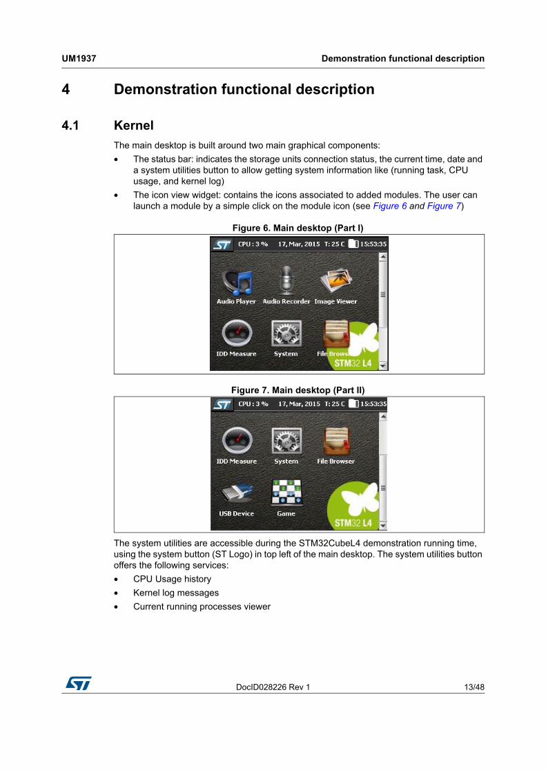
The main desktop is built around two main graphical components:
• The status bar: indicates the storage units connection status, the current time, date and a system utilities button to allow getting system information like (running task, CPU usage, and kernel log)
• The icon view widget: contains the icons associated to added modules. The user can launch a module by a simple click on the module icon (see Figure 6 and Figure 7)
Figure 6. Main desktop (Part I)
Figure 7. Main desktop (Part II)
The system utilities are accessible during the STM32CubeL4 demonstration running time, using the system button (ST Logo) in top left of the main desktop. The system utilities button offers the following services:
• CPU Usage history
• Kernel log messages
• Current running processes viewer
Demonstration functional description UM1937
14/48 DocID028226 Rev 1
4.1.1 CPU usage
The CPU usage utility provides a graphical representation of the CPU usage evolution (Figure 8) during the demonstration run time starting for the first time it was launched. Note that once launched the CPU usage utilities keep running in background and can be restored any time.
Figure 8. CPU usage
4.1.2 Kernel log
The kernel log utility gathers all the kernel and module messages and save them into a dedicated internal buffer. The log messages can be visualized any time during the demonstration run time.
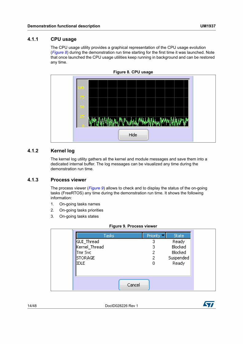
4.1.3 Process viewer
The process viewer (Figure 9) allows to check and to display the status of the on-going tasks (FreeRTOS) any time during the demonstration run time. It shows the following information:
1. On-going tasks names
2. On-going tasks priorities
3. On-going tasks states
Figure 9. Process viewer
DocID028226 Rev 1 15/48
UM1937 Demonstration functional description
47
4.2 Modules
4.2.1 System
Overview
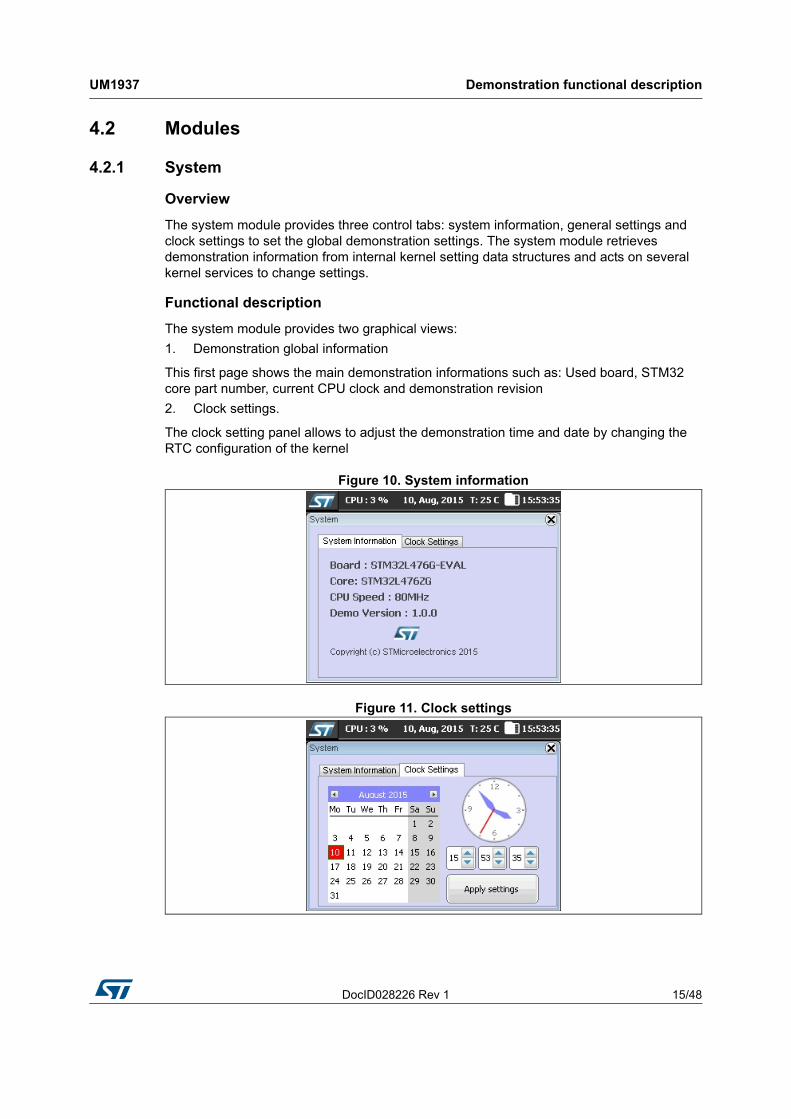
The system module provides three control tabs: system information, general settings and clock settings to set the global demonstration settings. The system module retrieves demonstration information from internal kernel setting data structures and acts on several kernel services to change settings.
Functional description
The system module provides two graphical views:
1. Demonstration global information
This first page shows the main demonstration informations such as: Used board, STM32 core part number, current CPU clock and demonstration revision
2. Clock settings.
The clock setting panel allows to adjust the demonstration time and date by changing the RTC configuration of the kernel
Figure 10. System information
Figure 11. Clock settings
Demonstration functional description UM1937
16/48 DocID028226 Rev 1
4.2.2 Audio player
Overview
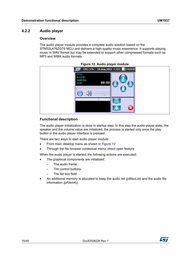
The audio player module provides a complete audio solution based on the STM32L476ZGT6 MCU and delivers a high-quality music experience. It supports playing music in WAV format but may be extended to support other compressed formats such as MP3 and WMA audio formats.
Figure 12. Audio player module
Functional description
The audio player initialization is done in startup step. In this step the audio player state, the speaker and the volume value are initialized, the process is started only once the play button in the audio player interface is pressed.
There are two ways to start audio player module:
• From main desktop menu as shown in Figure 12
• Through the file browser contextual menu: direct open feature
When the audio player is started, the following actions are executed:
• The graphical components are initialized:
– The audio frame
– The control buttons
– The list box field
• An additional memory is allocated to keep the audio list (pWavList) and the audio file information (pFileInfo).
DocID028226 Rev 1 17/48
UM1937 Demonstration functional description
47
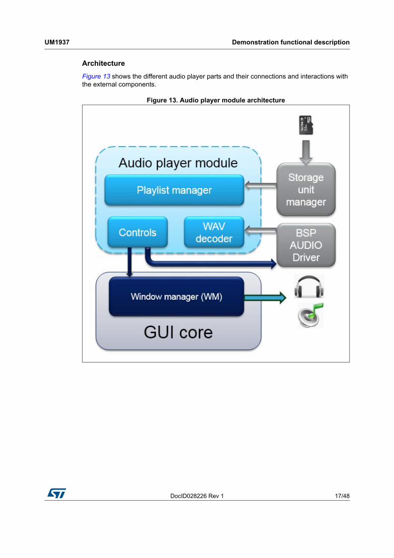
Architecture
Figure 13 shows the different audio player parts and their connections and interactions with the external components.
Figure 13. Audio player module architecture
Demonstration functional description UM1937
18/48 DocID028226 Rev 1
Data structure used
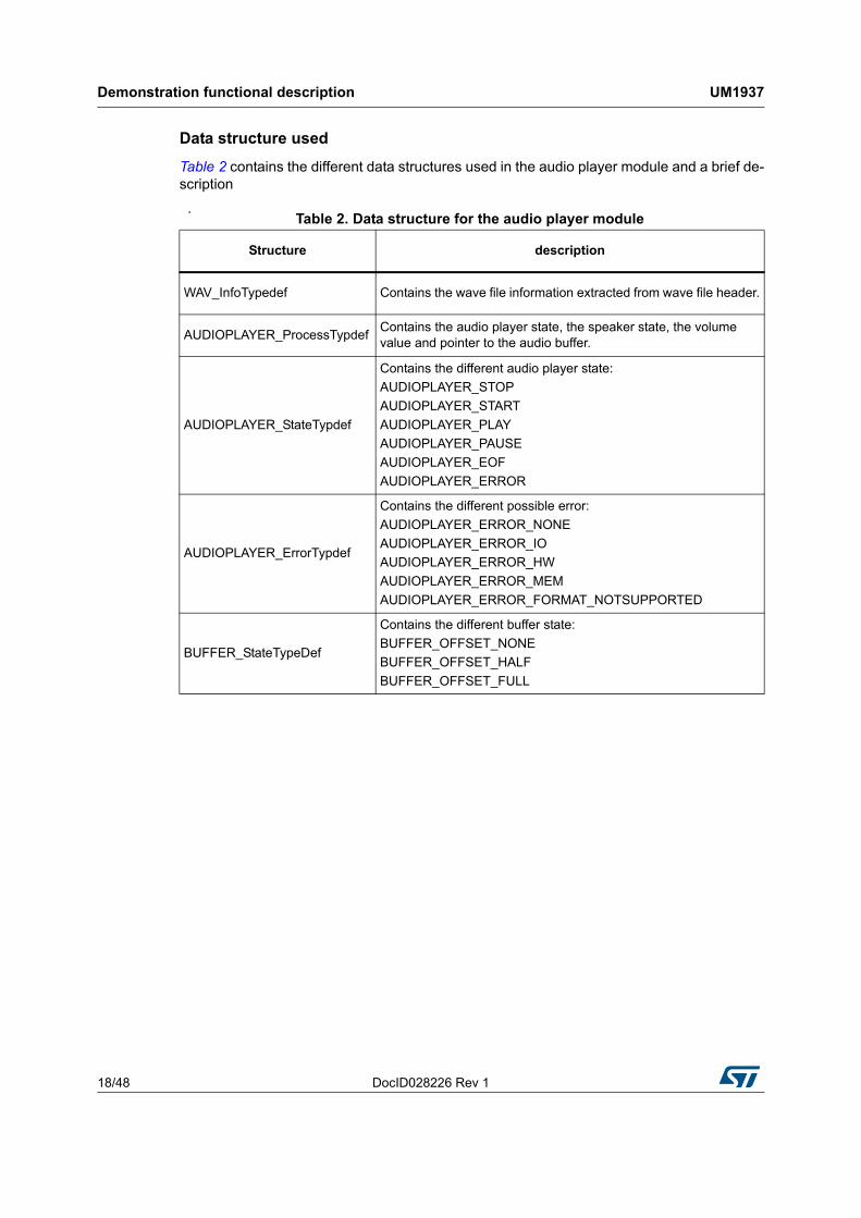
Table 2 contains the different data structures used in the audio player module and a brief de-scription
.Table 2. Data structure for the audio player module
Structure description
WAV_InfoTypedef Contains the wave file information extracted from wave file header.
AUDIOPLAYER_ProcessTypdefContains the audio player state, the speaker state, the volume value and pointer to the audio buffer.
AUDIOPLAYER_StateTypdef
Contains the different audio player state:
AUDIOPLAYER_STOP
AUDIOPLAYER_START
AUDIOPLAYER_PLAY
AUDIOPLAYER_PAUSE
AUDIOPLAYER_EOF
AUDIOPLAYER_ERROR
AUDIOPLAYER_ErrorTypdef
Contains the different possible error:
AUDIOPLAYER_ERROR_NONE
AUDIOPLAYER_ERROR_IO
AUDIOPLAYER_ERROR_HW
AUDIOPLAYER_ERROR_MEM
AUDIOPLAYER_ERROR_FORMAT_NOTSUPPORTED
BUFFER_StateTypeDef
Contains the different buffer state:
BUFFER_OFFSET_NONE
BUFFER_OFFSET_HALF
BUFFER_OFFSET_FULL
DocID028226 Rev 1 19/48
UM1937 Demonstration functional description
47
Audio player Control
l
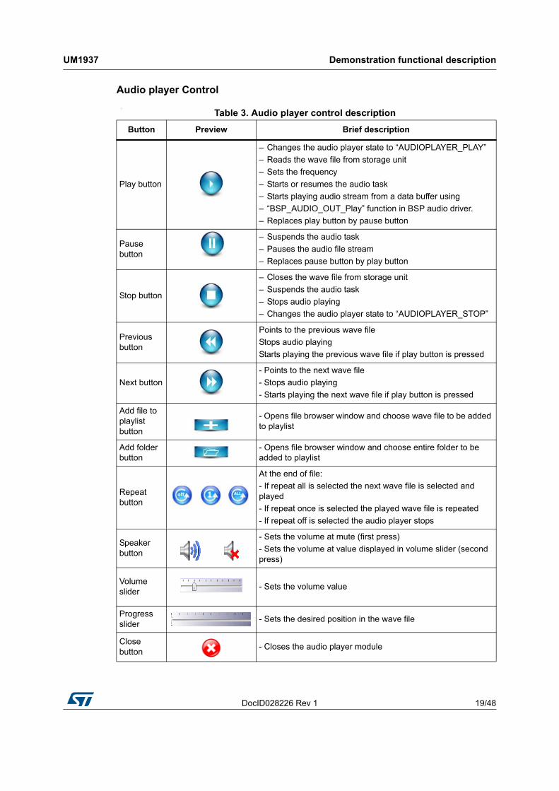
Table 3. Audio player control description
Button Preview Brief description
Play button
– Changes the audio player state to “AUDIOPLAYER_PLAY”
– Reads the wave file from storage unit
– Sets the frequency
– Starts or resumes the audio task
– Starts playing audio stream from a data buffer using
– “BSP_AUDIO_OUT_Play” function in BSP audio driver.
– Replaces play button by pause button
Pause button
– Suspends the audio task
– Pauses the audio file stream
– Replaces pause button by play button
Stop button
– Closes the wave file from storage unit
– Suspends the audio task
– Stops audio playing
– Changes the audio player state to “AUDIOPLAYER_STOP”
Previous button
Points to the previous wave file
Stops audio playing
Starts playing the previous wave file if play button is pressed
Next button
- Points to the next wave file
- Stops audio playing
- Starts playing the next wave file if play button is pressed
Add file to playlist button
- Opens file browser window and choose wave file to be added to playlist
Add folder button
- Opens file browser window and choose entire folder to be added to playlist
Repeat button
At the end of file:
- If repeat all is selected the next wave file is selected and played
- If repeat once is selected the played wave file is repeated
- If repeat off is selected the audio player stops
Speaker button
- Sets the volume at mute (first press)
- Sets the volume at value displayed in volume slider (second press)
Volume slider
- Sets the volume value
Progress slider
- Sets the desired position in the wave file
Close button
- Closes the audio player module
Demonstration functional description UM1937
20/48 DocID028226 Rev 1
4.2.3 Audio recorder
Overview
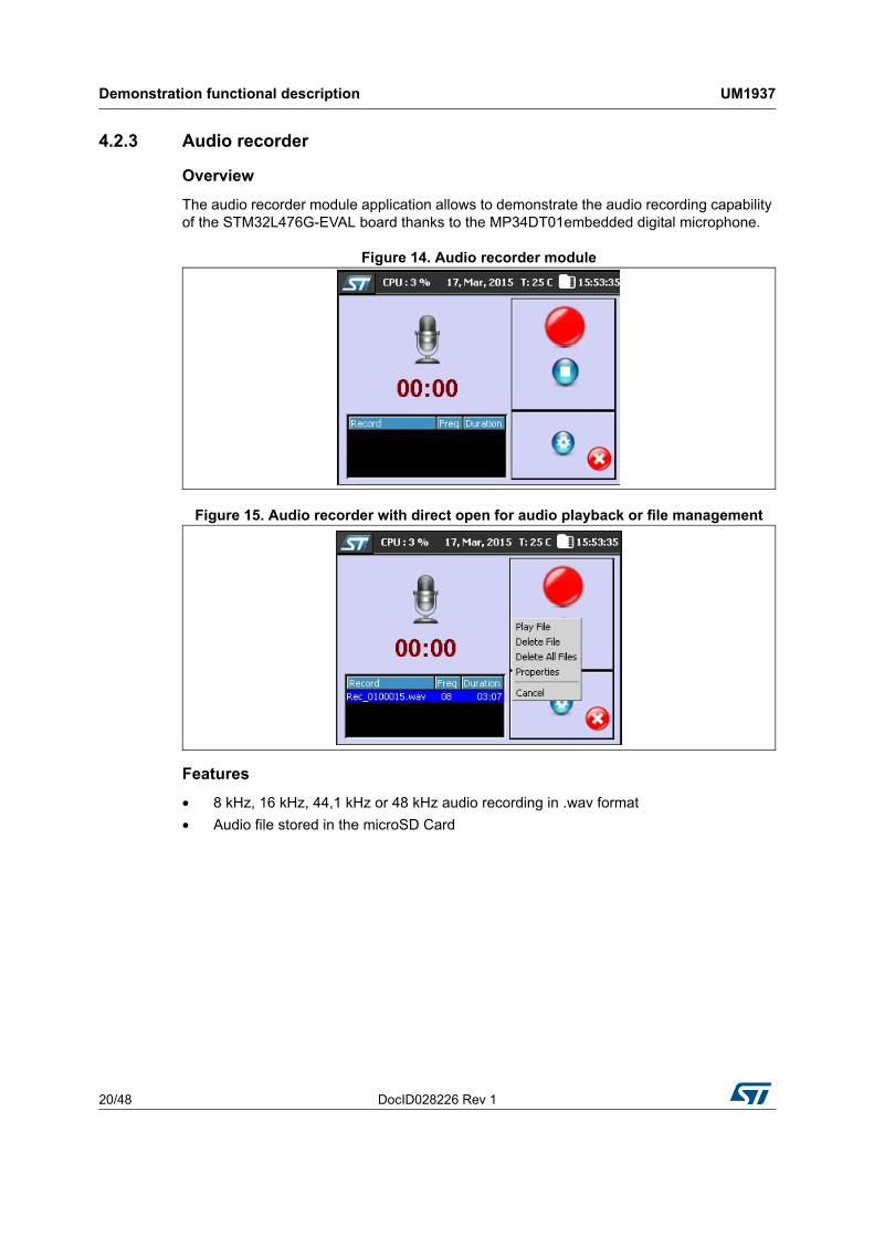
The audio recorder module application allows to demonstrate the audio recording capability of the STM32L476G-EVAL board thanks to the MP34DT01embedded digital microphone.
Figure 14. Audio recorder module
Figure 15. Audio recorder with direct open for audio playback or file management
Features
• 8 kHz, 16 kHz, 44,1 kHz or 48 kHz audio recording in .wav format
• Audio file stored in the microSD Card
DocID028226 Rev 1 21/48
UM1937 Demonstration functional description
47
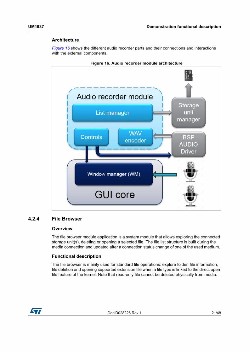
Architecture
Figure 16 shows the different audio recorder parts and their connections and interactions with the external components.
Figure 16. Audio recorder module architecture
4.2.4 File Browser
Overview
The file browser module application is a system module that allows exploring the connected storage unit(s), deleting or opening a selected file. The file list structure is built during the media connection and updated after a connection status change of one of the used medium.
Functional description
The file browser is mainly used for standard file operations: explore folder, file information, file deletion and opening supported extension file when a file type is linked to the direct open file feature of the kernel. Note that read-only file cannot be deleted physically from media.
Demonstration functional description UM1937
22/48 DocID028226 Rev 1
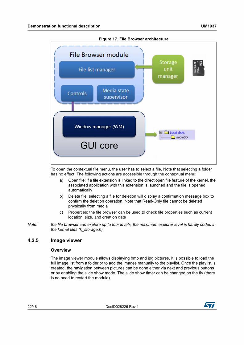
Figure 17. File Browser architecture
To open the contextual file menu, the user has to select a file. Note that selecting a folder has no effect. The following actions are accessible through the contextual menu:
a) Open file: if a file extension is linked to the direct open file feature of the kernel, the associated application with this extension is launched and the file is opened automatically
b) Delete file: selecting a file for deletion will display a confirmation message box to confirm the deletion operation. Note that Read-Only file cannot be deleted physically from media
c) Properties: the file browser can be used to check file properties such as current location, size, and creation date
Note: the file browser can explore up to four levels, the maximum explorer level is hardly coded in the kernel files (k_storage.h).
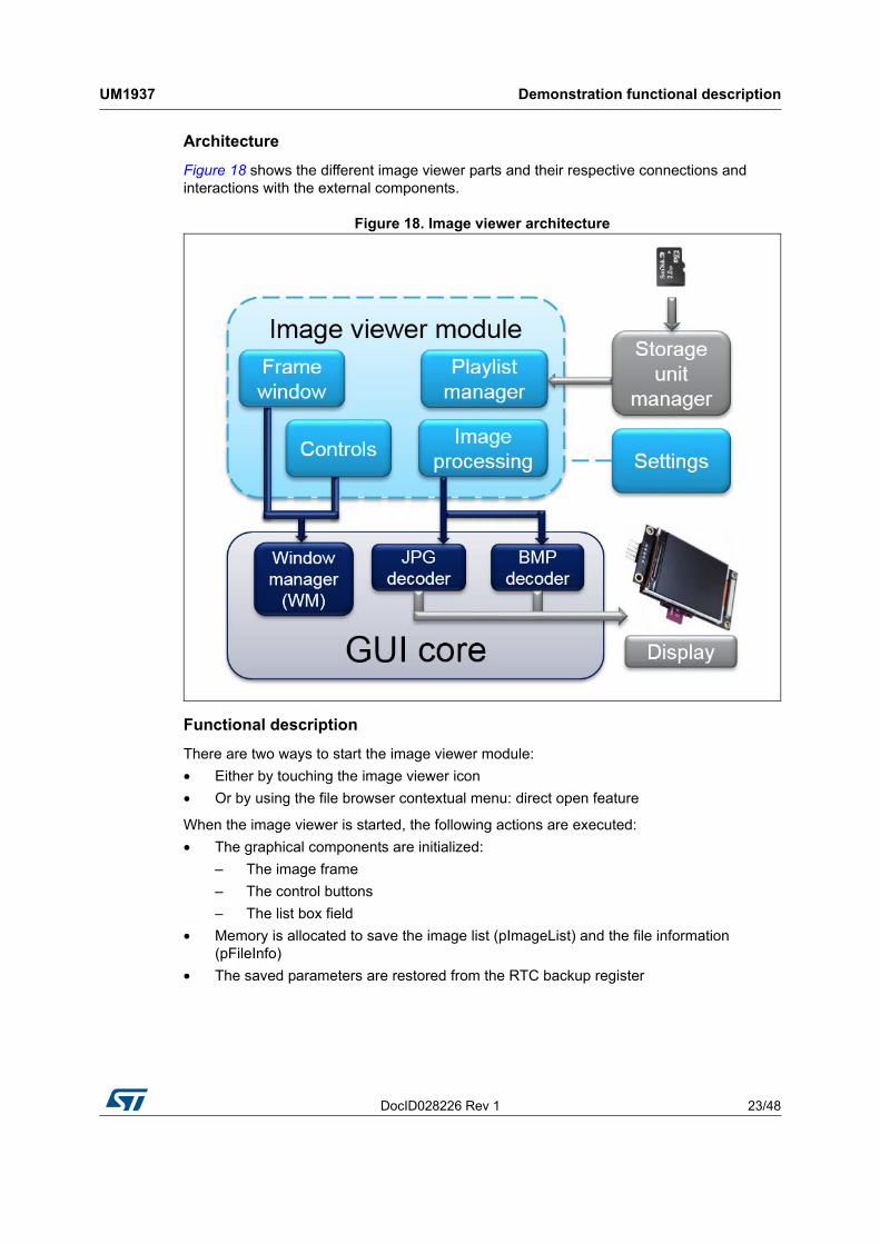
4.2.5 Image viewer
Overview
The image viewer module allows displaying bmp and jpg pictures. It is possible to load the full image list from a folder or to add the images manually to the playlist. Once the playlist is created, the navigation between pictures can be done either via next and previous buttons or by enabling the slide show mode. The slide show timer can be changed on the fly (there is no need to restart the module).
DocID028226 Rev 1 23/48
UM1937 Demonstration functional description
47
Architecture
Figure 18 shows the different image viewer parts and their respective connections and interactions with the external components.
Figure 18. Image viewer architecture
Functional description
There are two ways to start the image viewer module:
• Either by touching the image viewer icon
• Or by using the file browser contextual menu: direct open feature
When the image viewer is started, the following actions are executed:
• The graphical components are initialized:
– The image frame
– The control buttons
– The list box field
• Memory is allocated to save the image list (pImageList) and the file information (pFileInfo)
• The saved parameters are restored from the RTC backup register
Demonstration functional description UM1937
24/48 DocID028226 Rev 1
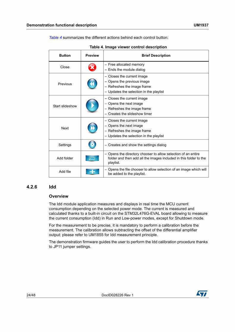
Table 4 summarizes the different actions behind each control button:
4.2.6 Idd
Overview
The Idd module application measures and displays in real time the MCU current consumption depending on the selected power mode. The current is measured and calculated thanks to a built-in circuit on the STM32L476G-EVAL board allowing to measure the current consumption (Idd) in Run and Low-power modes, except for Shutdown mode.
For the measurement to be precise, it is mandatory to perform a calibration before the measurement. The calibration allows subtracting the offset of the differential amplifier output: please refer to UM1855 for Idd measurement principle.
The demonstration firmware guides the user to perform the Idd calibration procedure thanks to JP11 jumper settings.
Table 4. Image viewer control description
Button Preview Brief Description
Close– Free allocated memory
– Ends the module dialog
Previous
– Closes the current image
– Opens the previous image
– Refreshes the image frame
– Updates the selection in the playlist
Start slideshow
– Closes the current image
– Opens the next image
– Refreshes the image frame
– Creates the slideshow timer
Next
– Closes the current image
– Opens the next image
– Refreshes the image frame
– Updates the selection in the playlist
Settings – Creates and show the settings dialog
Add folder– Opens the directory chooser to allow selection of an entire
folder and then add all the images included in this folder to the playlist.
Add file– Opens the file chooser to allow selection of an image which will
be added to the playlist.
DocID028226 Rev 1 25/48
UM1937 Demonstration functional description
47
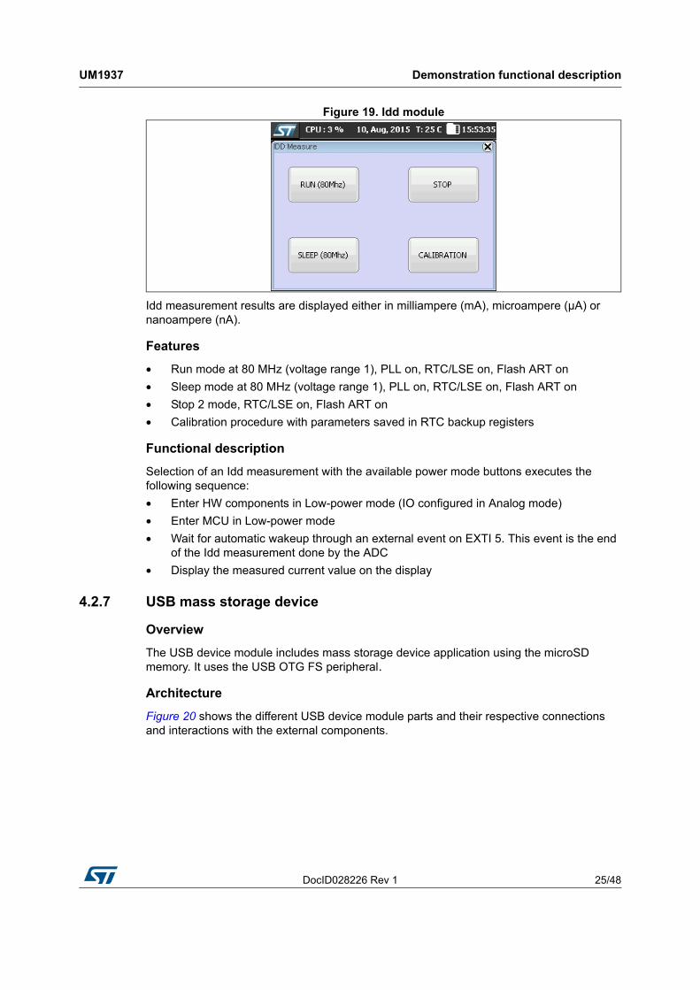
Figure 19. Idd module
Idd measurement results are displayed either in milliampere (mA), microampere (µA) or nanoampere (nA).
Features
• Run mode at 80 MHz (voltage range 1), PLL on, RTC/LSE on, Flash ART on
• Sleep mode at 80 MHz (voltage range 1), PLL on, RTC/LSE on, Flash ART on
• Stop 2 mode, RTC/LSE on, Flash ART on
• Calibration procedure with parameters saved in RTC backup registers
Functional description
Selection of an Idd measurement with the available power mode buttons executes the following sequence:
• Enter HW components in Low-power mode (IO configured in Analog mode)
• Enter MCU in Low-power mode
• Wait for automatic wakeup through an external event on EXTI 5. This event is the end of the Idd measurement done by the ADC
• Display the measured current value on the display
4.2.7 USB mass storage device
Overview
The USB device module includes mass storage device application using the microSD memory. It uses the USB OTG FS peripheral.
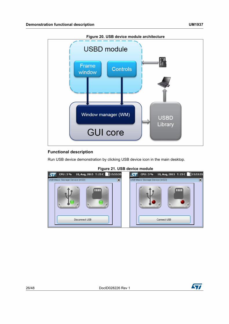
Architecture
Figure 20 shows the different USB device module parts and their respective connections and interactions with the external components.
Demonstration functional description UM1937
26/48 DocID028226 Rev 1
Figure 20. USB device module architecture
Functional description
Run USB device demonstration by clicking USB device icon in the main desktop.
Figure 21. USB device module
DocID028226 Rev 1 27/48
UM1937 Demonstration functional description
47
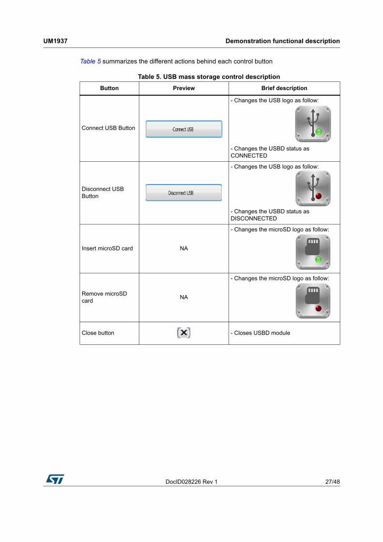
Table 5 summarizes the different actions behind each control button
:
Table 5. USB mass storage control description
Button Preview Brief description
Connect USB Button
- Changes the USB logo as follow:
- Changes the USBD status as CONNECTED
Disconnect USB Button
- Changes the USB logo as follow:
- Changes the USBD status as DISCONNECTED
Insert microSD card NA
- Changes the microSD logo as follow:
Remove microSD card
NA
- Changes the microSD logo as follow:
Close button
- Closes USBD module
Demonstration firmware settings UM1937
28/48 DocID028226 Rev 1
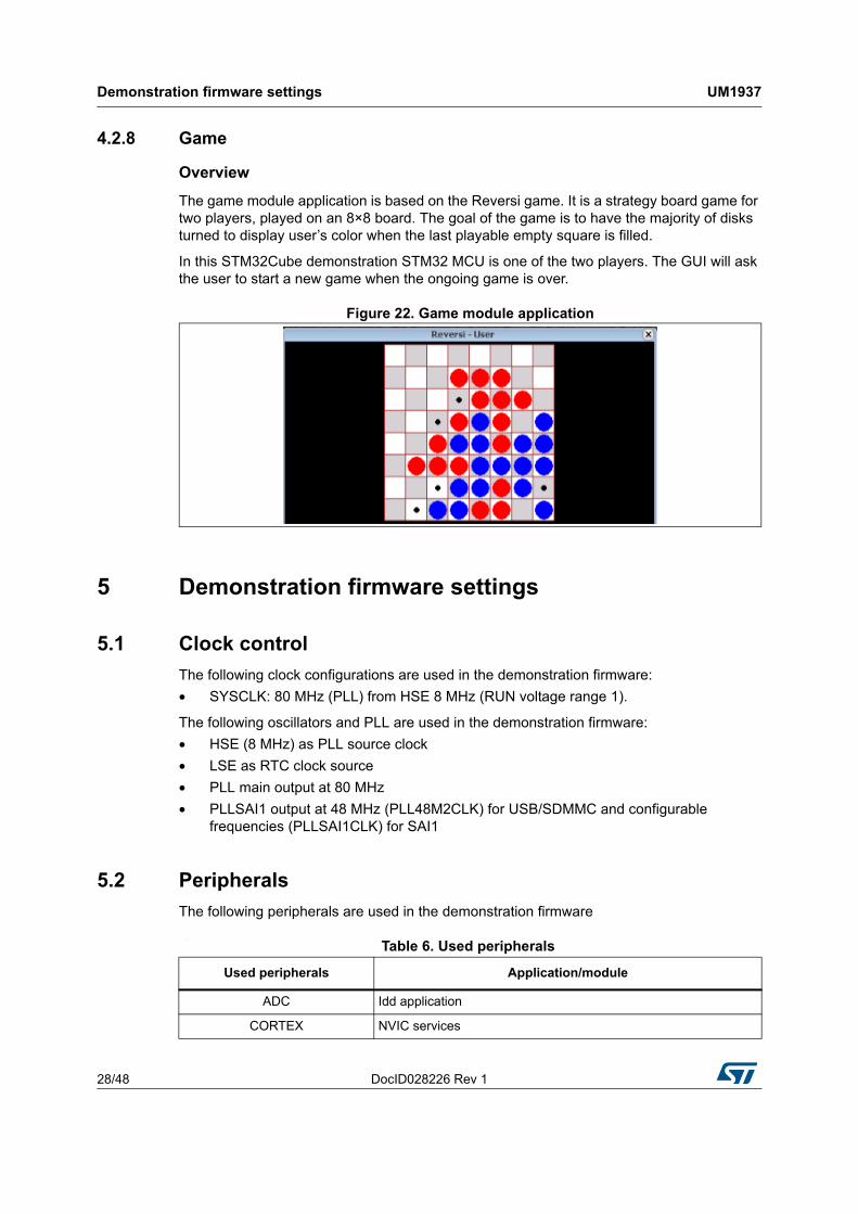
4.2.8 Game
Overview
The game module application is based on the Reversi game. It is a strategy board game for two players, played on an 8×8 board. The goal of the game is to have the majority of disks turned to display user’s color when the last playable empty square is filled.
In this STM32Cube demonstration STM32 MCU is one of the two players. The GUI will ask the user to start a new game when the ongoing game is over.
Figure 22. Game module application
5 Demonstration firmware settings
5.1 Clock control
The following clock configurations are used in the demonstration firmware:
• SYSCLK: 80 MHz (PLL) from HSE 8 MHz (RUN voltage range 1).
The following oscillators and PLL are used in the demonstration firmware:
• HSE (8 MHz) as PLL source clock
• LSE as RTC clock source
• PLL main output at 80 MHz
• PLLSAI1 output at 48 MHz (PLL48M2CLK) for USB/SDMMC and configurable frequencies (PLLSAI1CLK) for SAI1
5.2 Peripherals
The following peripherals are used in the demonstration firmware
:
Table 6. Used peripherals
Used peripherals Application/module
ADC Idd application
CORTEX NVIC services
DocID028226 Rev 1 29/48
UM1937 Demonstration firmware settings
47
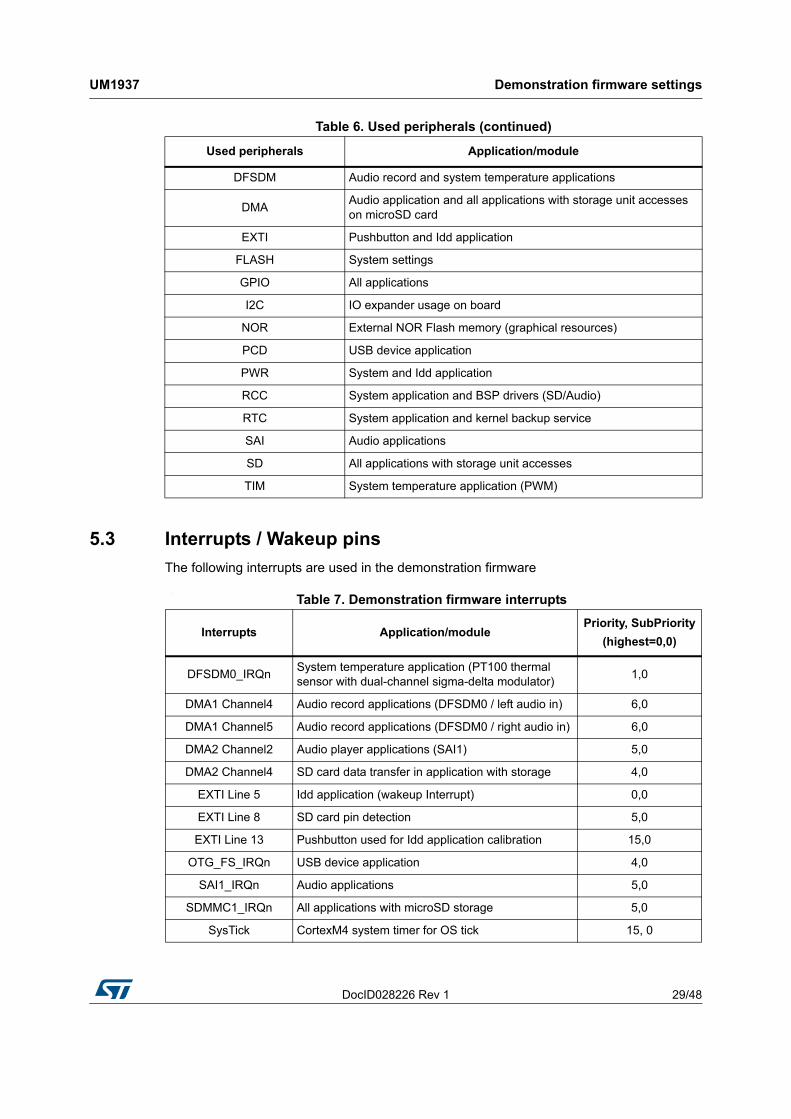
5.3 Interrupts / Wakeup pins
The following interrupts are used in the demonstration firmware
:
DFSDM Audio record and system temperature applications
DMAAudio application and all applications with storage unit accesses on microSD card
EXTI Pushbutton and Idd application
FLASH System settings
GPIO All applications
I2C IO expander usage on board
NOR External NOR Flash memory (graphical resources)
PCD USB device application
PWR System and Idd application
RCC System application and BSP drivers (SD/Audio)
RTC System application and kernel backup service
SAI Audio applications
SD All applications with storage unit accesses
TIM System temperature application (PWM)
Table 6. Used peripherals (continued)
Used peripherals Application/module
Table 7. Demonstration firmware interrupts
Interrupts Application/modulePriority, SubPriority
(highest=0,0)
DFSDM0_IRQnSystem temperature application (PT100 thermal sensor with dual-channel sigma-delta modulator)
1,0
DMA1 Channel4 Audio record applications (DFSDM0 / left audio in) 6,0
DMA1 Channel5 Audio record applications (DFSDM0 / right audio in) 6,0
DMA2 Channel2 Audio player applications (SAI1) 5,0
DMA2 Channel4 SD card data transfer in application with storage 4,0
EXTI Line 5 Idd application (wakeup Interrupt) 0,0
EXTI Line 8 SD card pin detection 5,0
EXTI Line 13 Pushbutton used for Idd application calibration 15,0
OTG_FS_IRQn USB device application 4,0
SAI1_IRQn Audio applications 5,0
SDMMC1_IRQn All applications with microSD storage 5,0
SysTick CortexM4 system timer for OS tick 15, 0
Demonstration firmware settings UM1937
30/48 DocID028226 Rev 1
5.4 System memory configuration
The following system memory areas are used in the demonstration firmware
:
5.5 FreeRTOS resources
The STM32L476G-EVAL firmware demonstration is designed on top of CMSIS-OS drivers based on FreeRTOS. Resources used in the firmware demonstration are listed hereafter.
As a reminder FreeRTOS configuration is described in FreeRTOSConfig.h file.
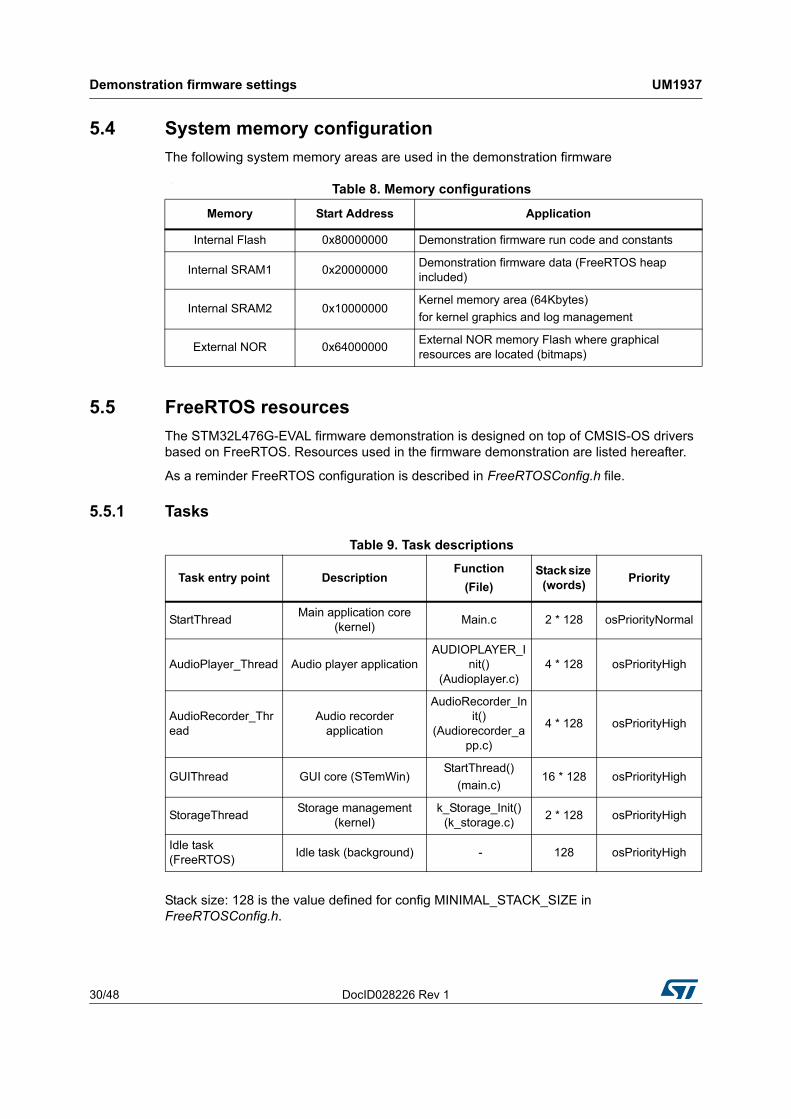
5.5.1 Tasks
Stack size: 128 is the value defined for config MINIMAL_STACK_SIZE in FreeRTOSConfig.h.
Table 8. Memory configurations
Memory Start Address Application
Internal Flash 0x80000000 Demonstration firmware run code and constants
Internal SRAM1 0x20000000Demonstration firmware data (FreeRTOS heap included)
Internal SRAM2 0x10000000Kernel memory area (64Kbytes)
for kernel graphics and log management
External NOR 0x64000000External NOR memory Flash where graphical resources are located (bitmaps)
Table 9. Task descriptions
Task entry point DescriptionFunction
(File)Stack size
(words)Priority
StartThreadMain application core
(kernel)Main.c 2 * 128 osPriorityNormal
AudioPlayer_Thread Audio player applicationAUDIOPLAYER_I
nit() (Audioplayer.c)
4 * 128 osPriorityHigh
AudioRecorder_Thread
Audio recorder application
AudioRecorder_Init()
(Audiorecorder_app.c)
4 * 128 osPriorityHigh
GUIThread GUI core (STemWin)StartThread()
(main.c)16 * 128 osPriorityHigh
StorageThreadStorage management
(kernel)k_Storage_Init()
(k_storage.c)2 * 128 osPriorityHigh
Idle task (FreeRTOS)
Idle task (background) - 128 osPriorityHigh
DocID028226 Rev 1 31/48
UM1937 Demonstration firmware settings
47
5.5.2 Message queues
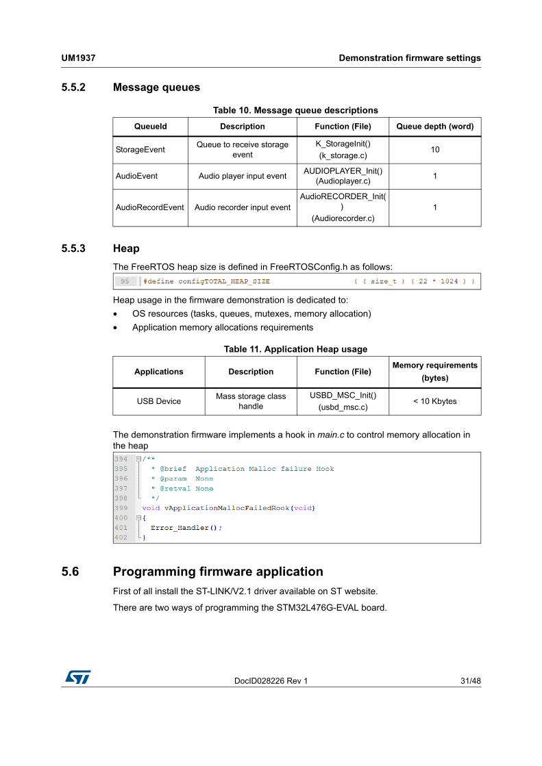
5.5.3 Heap
The FreeRTOS heap size is defined in FreeRTOSConfig.h as follows:
Heap usage in the firmware demonstration is dedicated to:
• OS resources (tasks, queues, mutexes, memory allocation)
• Application memory allocations requirements
The demonstration firmware implements a hook in main.c to control memory allocation in the heap
5.6 Programming firmware application
First of all install the ST-LINK/V2.1 driver available on ST website.
There are two ways of programming the STM32L476G-EVAL board.
Table 10. Message queue descriptions
QueueId Description Function (File) Queue depth (word)
StorageEventQueue to receive storage
eventK_StorageInit()
(k_storage.c)10
AudioEvent Audio player input eventAUDIOPLAYER_Init()
(Audioplayer.c)1
AudioRecordEvent Audio recorder input eventAudioRECORDER_Init(
)
(Audiorecorder.c)1
Table 11. Application Heap usage
Applications Description Function (File)Memory requirements
(bytes)
USB DeviceMass storage class
handleUSBD_MSC_Init()
(usbd_msc.c)< 10 Kbytes
Kernel description UM1937
32/48 DocID028226 Rev 1
5.6.1 Using binary file
Upload the binary STM32CubeDemo_STM32L476G_EVAL-VX.Y.Z.hex from the firmware package available under Projects\STM32L476G_EVAL\Demonstrations\MB1144\Binary using user’s preferred in-system programming tool.
Make sure that the external loader for M29W128GL_STM32L476G_EVAL is selected to program the graphical resources in the external NOR flash.
5.6.2 Using pre-configured projects
Choose one of the supported tool chains and follow the steps below:
• Open the application folder: Projects\STM32L476G_EVAL\Demonstrations\MB1144
• Choose the desired IDE project (EWARM for IAR, MDK-ARM for Keil)
• Double click on the project file (for example Project.eww for EWARM)
• Rebuild all files: go to Project and select Rebuild all
• Load the project image: go to Project and select Debug
• Run the program: go to Debug and select Go
6 Kernel description
6.1 Overview
The role of the demonstration kernel is mainly to provide a generic platform that controls and monitors all the application processes with a minimum memory consumption. The kernel provides a set of friendly services that simplify module implementation by allowing access to all the hardware and firmware resources through the following tasks and services:
• Hardware and modules initialization:
– BSP initialization (LEDs, touchscreen, LCD, RTC, audio, SRAM and NOR)
• Graphical and main menu management
• Memory management
• Storage management (microSD card)
• System monitoring and settings
• CPU utilities (CPU usage, running tasks)
6.2 Kernel core files
Table 12. Kernel core file description
Function Description
main.c Main program file
stm32l4xx_it.c Interrupt handlers for the application
k_calibration.c Touchscreen kernel calibration manager
DocID028226 Rev 1 33/48
UM1937 Kernel description
47
6.3 Kernel initialization
The first task of the kernel is to initialize the hardware and firmware resources to make them available to its internal processes and the modules around it. The kernel starts by initializing the HAL, system clocks and then the hardware resources needed during the middleware components:
• LEDs
• Pushbutton
• Touchscreen
• IO expanders
• SRAM
• NOR Flash
• RTC
Once the low level resources are initialized, the kernel performs the STemWin GUI library initialization and prepares the following common services:
• Memory manager
• Storage unit
• Module manager
• Kernel log
Upon full initialization phase, the kernel adds and links the system and user modules to the demonstration core.
k_mem.c Kernel memory manager
k_menu.c Kernel menu and desktop manager
k_module.c Module manager
k_module_res.c Module graphical resources manager
k_res.c Kernel resources manager
k_rtc.c Real-time clock manager
k_sd_diskio.c microSD card manager
k_startup.c Demonstration startup windowing process
k_storage.c Storage manager
k_temperature.c Temperature monitoring manager
Table 12. Kernel core file description (continued)
Function Description
Kernel description UM1937
34/48 DocID028226 Rev 1
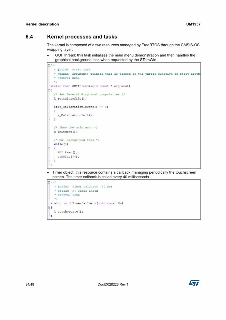
6.4 Kernel processes and tasks
The kernel is composed of a two resources managed by FreeRTOS through the CMSIS-OS wrapping layer:
• GUI Thread: this task initializes the main menu demonstration and then handles the graphical background task when requested by the STemWin.
• Timer object: this resource contains a callback managing periodically the touchscreen screen. The timer callback is called every 40 milliseconds
DocID028226 Rev 1 35/48
UM1937 Kernel description
47
6.5 Kernel graphical aspect
The STM32Cube demonstration is built around the STemWin graphical library, based on SEGGER emWin one. STemWin is a professional graphical stack library, enabling graphical user interfaces (GUI) building up with any STM32, any LCD and any LCD controller, taking benefit from STM32 hardware accelerations, whenever possible. The graphical aspect of the STM32Cube demonstration is divided into two main graphical components:
• The startup window: showing the progress of the hardware and software initialization.
• The main desktop that handles the main demonstration menu and the numerous kernel and modules control, see Section 4.1: Kernel
6.6 Kernel menu management
The main demonstration menu is initialized and launched by the GUI thread. Before the initialization of the menu the following actions are performed:
• Draw the background image
• Restore general settings from backup memory
• Setup the main desktop callback to manage main window messages
The icon view widget: contains the icons associated to added modules. The user can launch a module by a simple click on the module icon.
Kernel description UM1937
36/48 DocID028226 Rev 1
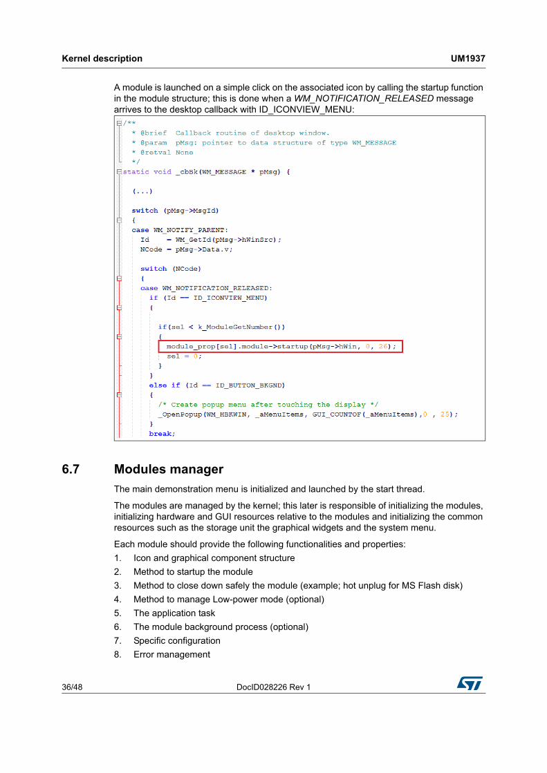
A module is launched on a simple click on the associated icon by calling the startup function in the module structure; this is done when a WM_NOTIFICATION_RELEASED message arrives to the desktop callback with ID_ICONVIEW_MENU:
6.7 Modules manager
The main demonstration menu is initialized and launched by the start thread.
The modules are managed by the kernel; this later is responsible of initializing the modules, initializing hardware and GUI resources relative to the modules and initializing the common resources such as the storage unit the graphical widgets and the system menu.
Each module should provide the following functionalities and properties:
1. Icon and graphical component structure
2. Method to startup the module
3. Method to close down safely the module (example; hot unplug for MS Flash disk)
4. Method to manage Low-power mode (optional)
5. The application task
6. The module background process (optional)
7. Specific configuration
8. Error management
DocID028226 Rev 1 37/48
UM1937 Kernel description
47
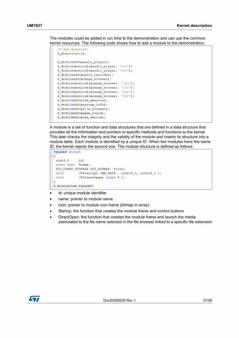
The modules could be added in run time to the demonstration and can use the common kernel resources. The following code shows how to add a module to the demonstration:
A module is a set of function and data structures that are defined in a data structure that provides all the information and pointers to specific methods and functions to the kernel. This later checks the integrity and the validity of the module and inserts its structure into a module table. Each module is identified by a unique ID. When two modules have the same ID, the kernel rejects the second one. The module structure is defined as follows:
• id: unique module identifier
• name: pointer to module name
• icon: pointer to module icon frame (bitmap in array)
• Startup: the function that creates the module frame and control buttons
• DirectOpen: the function that creates the module frame and launch the media associated to the file name selected in the file browser linked to a specific file extension
Kernel description UM1937
38/48 DocID028226 Rev 1
6.8 Backup and settings configuration
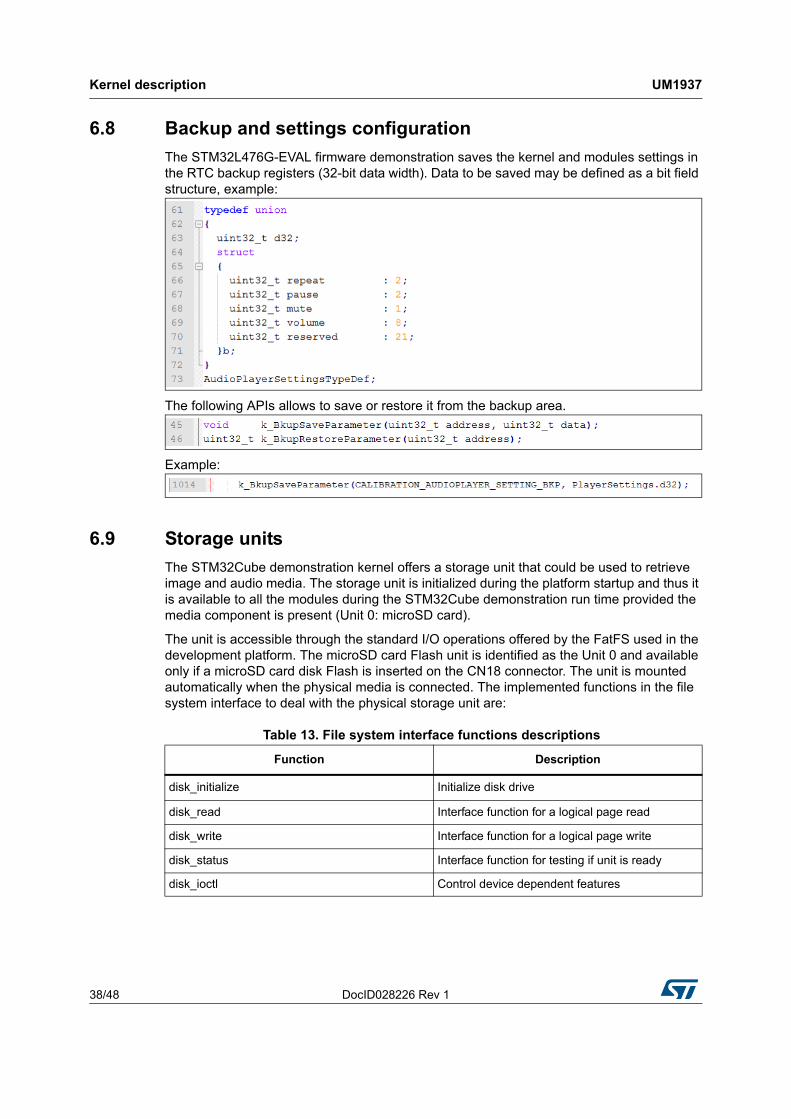
The STM32L476G-EVAL firmware demonstration saves the kernel and modules settings in the RTC backup registers (32-bit data width). Data to be saved may be defined as a bit field structure, example:
The following APIs allows to save or restore it from the backup area.
Example:
6.9 Storage units
The STM32Cube demonstration kernel offers a storage unit that could be used to retrieve image and audio media. The storage unit is initialized during the platform startup and thus it is available to all the modules during the STM32Cube demonstration run time provided the media component is present (Unit 0: microSD card).
The unit is accessible through the standard I/O operations offered by the FatFS used in the development platform. The microSD card Flash unit is identified as the Unit 0 and available only if a microSD card disk Flash is inserted on the CN18 connector. The unit is mounted automatically when the physical media is connected. The implemented functions in the file system interface to deal with the physical storage unit are:
Table 13. File system interface functions descriptions
Function Description
disk_initialize Initialize disk drive
disk_read Interface function for a logical page read
disk_write Interface function for a logical page write
disk_status Interface function for testing if unit is ready
disk_ioctl Control device dependent features
DocID028226 Rev 1 39/48
UM1937 Kernel description
47
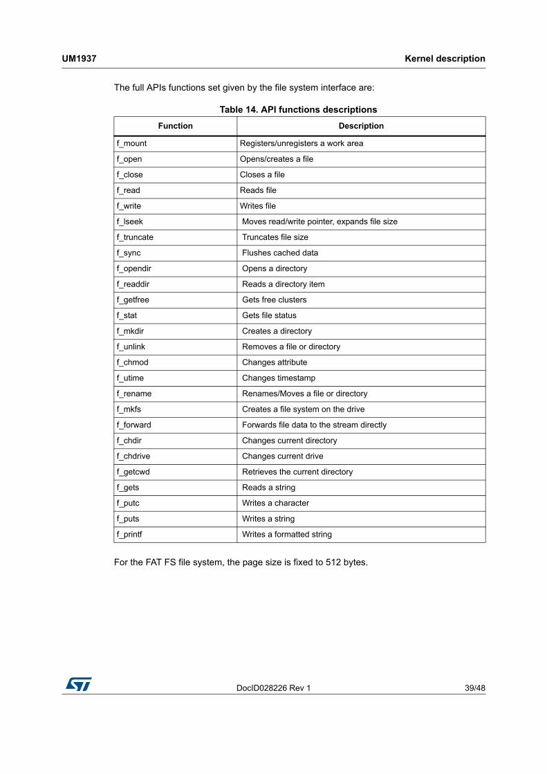
The full APIs functions set given by the file system interface are:
For the FAT FS file system, the page size is fixed to 512 bytes.
Table 14. API functions descriptions
Function Description
f_mount Registers/unregisters a work area
f_open Opens/creates a file
f_close Closes a file
f_read Reads file
f_write Writes file
f_lseek Moves read/write pointer, expands file size
f_truncate Truncates file size
f_sync Flushes cached data
f_opendir Opens a directory
f_readdir Reads a directory item
f_getfree Gets free clusters
f_stat Gets file status
f_mkdir Creates a directory
f_unlink Removes a file or directory
f_chmod Changes attribute
f_utime Changes timestamp
f_rename Renames/Moves a file or directory
f_mkfs Creates a file system on the drive
f_forward Forwards file data to the stream directly
f_chdir Changes current directory
f_chdrive Changes current drive
f_getcwd Retrieves the current directory
f_gets Reads a string
f_putc Writes a character
f_puts Writes a string
f_printf Writes a formatted string
How to create a new module UM1937
40/48 DocID028226 Rev 1
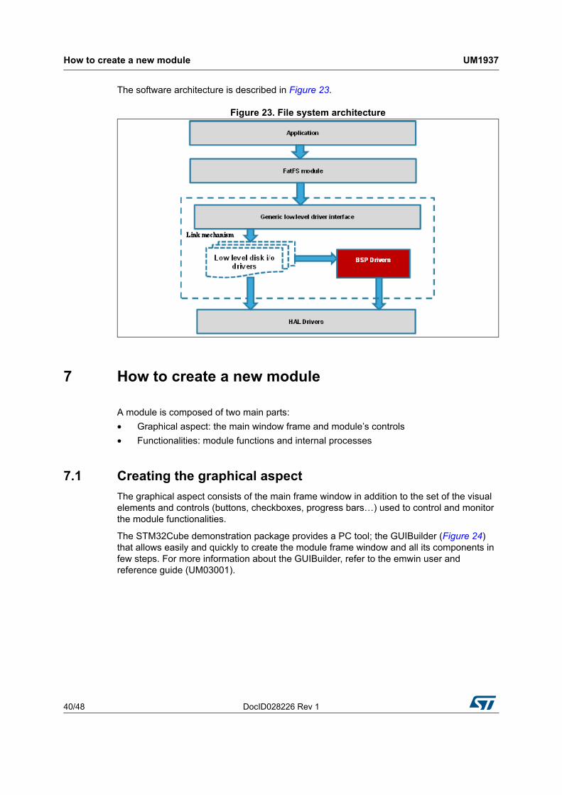
The software architecture is described in Figure 23.
Figure 23. File system architecture
7 How to create a new module
A module is composed of two main parts:
• Graphical aspect: the main window frame and module’s controls
• Functionalities: module functions and internal processes
7.1 Creating the graphical aspect
The graphical aspect consists of the main frame window in addition to the set of the visual elements and controls (buttons, checkboxes, progress bars…) used to control and monitor the module functionalities.
The STM32Cube demonstration package provides a PC tool; the GUIBuilder (Figure 24) that allows easily and quickly to create the module frame window and all its components in few steps. For more information about the GUIBuilder, refer to the emwin user and reference guide (UM03001).

DocID028226 Rev 1 41/48
UM1937 How to create a new module
47
Figure 24. The GUIBuilder overview
The GUIBuilder only takes few minutes to totally design the module appearances using “drag and drop” commands and then generate the source code file to be included into the application.
The file generated is composed of the following main parts:
• A resource table: it’s a table of type GUI_WIDGET_CREATE_INFO, which specifies all the widgets to be included in the dialog and also their respective positions and sizes
• A dialog callback routine: described more in detail in section (it is referred to as “main module callback routine”)
7.2 Graphics customization
After the basic module graphical appearance is created, it is then possible to customize some graphical elements, such as the buttons, by replacing the standard aspect by the user defined image. To do this, a new element drawing callback should be created and used instead of the original one.
Below is an example of a custom callback for the play button:
How to create a new module UM1937
42/48 DocID028226 Rev 1
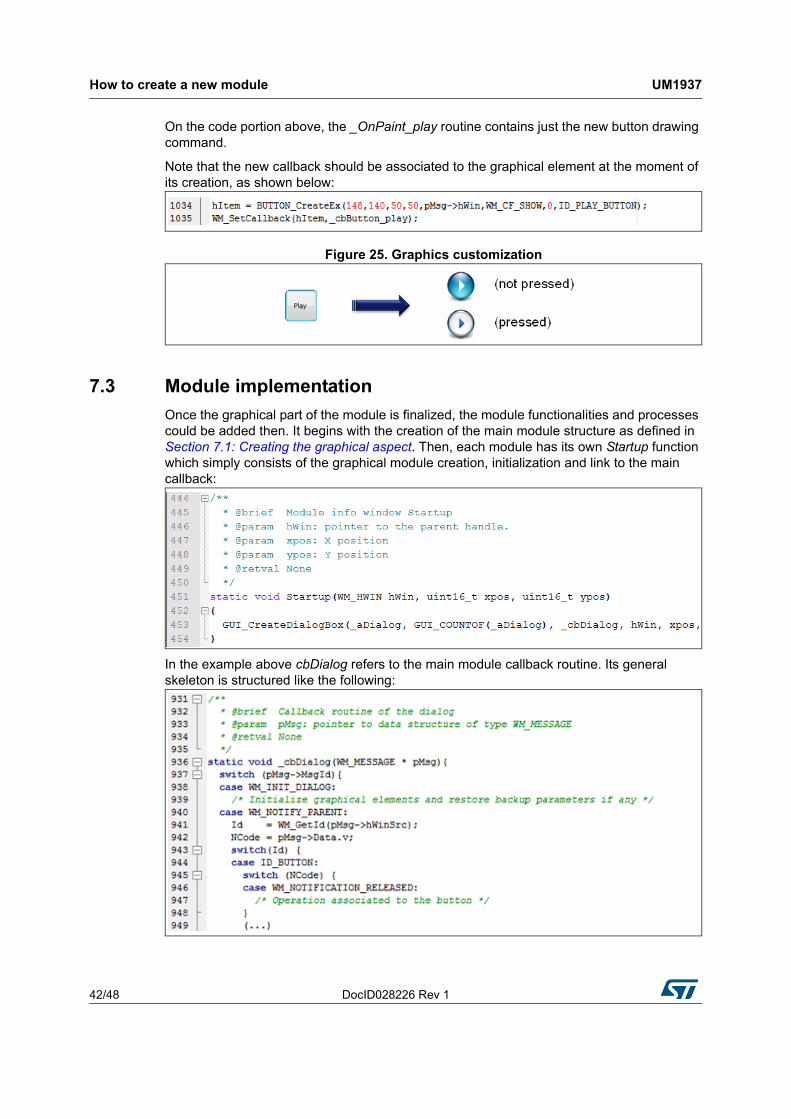
On the code portion above, the _OnPaint_play routine contains just the new button drawing command.
Note that the new callback should be associated to the graphical element at the moment of its creation, as shown below:
Figure 25. Graphics customization
7.3 Module implementation
Once the graphical part of the module is finalized, the module functionalities and processes could be added then. It begins with the creation of the main module structure as defined in Section 7.1: Creating the graphical aspect. Then, each module has its own Startup function which simply consists of the graphical module creation, initialization and link to the main callback:
In the example above cbDialog refers to the main module callback routine. Its general skeleton is structured like the following:
DocID028226 Rev 1 43/48
UM1937 How to create a new module
47
The list of windows messages presented in the code portion above (WM_INIT_DIALOG and WM_NOTIFY_PARENT) is not exhaustive, but it represents the essential message IDs used:
• WM_INIT_DIALOG: allows to initialize the graphical elements with their respective initial values. It is also possible here to restore the backup parameters (if any) that will be used during the dialog procedure
• WM_NOTIFY_PARENT: describes the dialog procedure, for example: define the behavior of each button.
The full list of window messages can be found in the WM.h file.
7.4 Adding a module to the main desktop
Once the module appearance and functionality are defined and created, the next step is to add the module to the main desktop view, this is done by adding it to the list (structure) of menu items: module_prop[ ], defined into k_module.h.
To do this, k_ModuleAdd() function should be called just after the module initialization into the main.c file.
Note that the maximum modules number in the demonstration package is limited to 15; this value can be changed by updating MAX_MODULES_NUM defined into k_module.c.
7.5 Module direct open
If there is a need to launch the module directly from the file browser contextual menu, an additional method should be added in the module structure for the direct open feature. This callback is often named _ModuleName_DirectOpen.
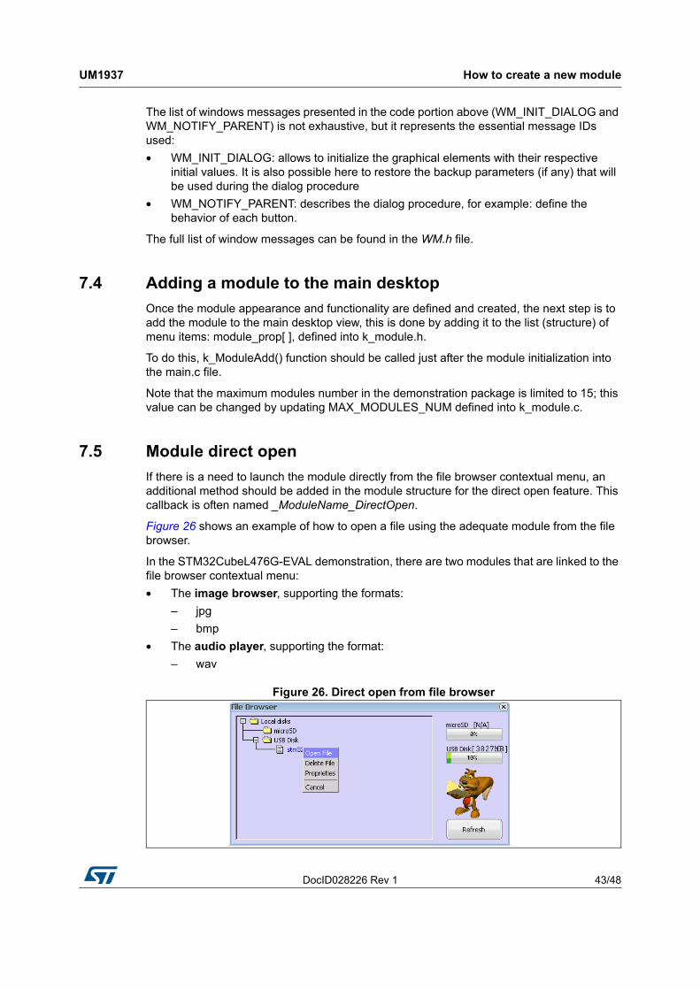
Figure 26 shows an example of how to open a file using the adequate module from the file browser.
In the STM32CubeL476G-EVAL demonstration, there are two modules that are linked to the file browser contextual menu:
• The image browser, supporting the formats:
– jpg
– bmp
• The audio player, supporting the format:
– wav
Figure 26. Direct open from file browser
Demonstration customization and configuration UM1937
44/48 DocID028226 Rev 1
Then, to link the module to the file browser open menu, the command k_ModuleOpenLink() is called after adding the module.
8 Demonstration customization and configuration
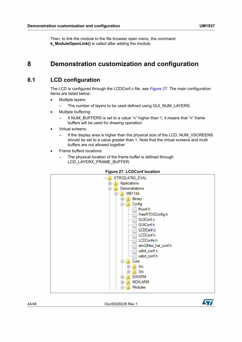
8.1 LCD configuration
The LCD is configured through the LCDConf.c file, see Figure 27. The main configuration items are listed below:
• Multiple layers:
– The number of layers to be used defined using GUI_NUM_LAYERS.
• Multiple buffering:
– If NUM_BUFFERS is set to a value “n” higher than 1, it means that “n” frame buffers will be used for drawing operation
• Virtual screens:
– If the display area is higher than the physical size of the LCD, NUM_VSCREENS should be set to a value greater than 1. Note that the virtual screens and multi buffers are not allowed together
• Frame buffers locations:
– The physical location of the frame buffer is defined through LCD_LAYERX_FRAME_BUFFER.
Figure 27. LCDConf location
DocID028226 Rev 1 45/48
UM1937 Demonstration customization and configuration
47
8.2 Layers management
In the STM32CubeL4 demonstration package with the STM32L476G-EVAL, GUI_NUM_LAYERS is set to 1: Layer 0 is dedicated to background display
More layers are not recommended to lighten the CPU load during the refresh tasks.
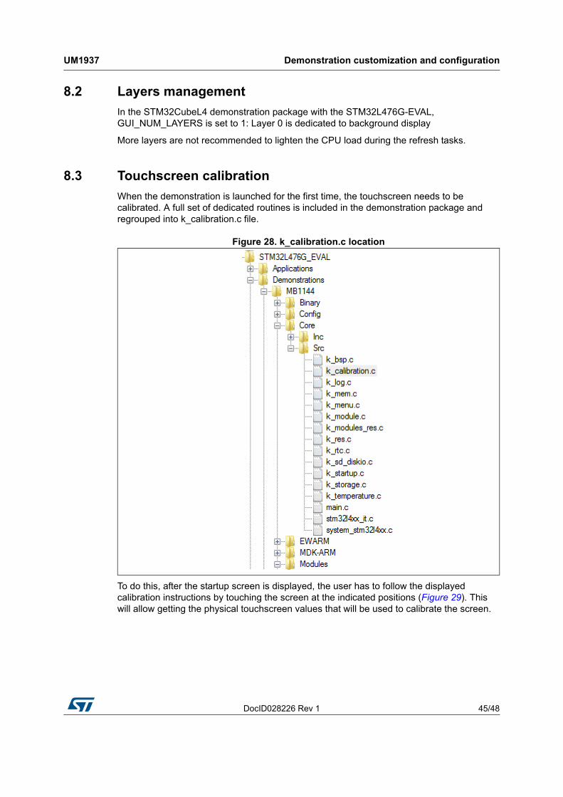
8.3 Touchscreen calibration
When the demonstration is launched for the first time, the touchscreen needs to be calibrated. A full set of dedicated routines is included in the demonstration package and regrouped into k_calibration.c file.
Figure 28. k_calibration.c location
To do this, after the startup screen is displayed, the user has to follow the displayed calibration instructions by touching the screen at the indicated positions (Figure 29). This will allow getting the physical touchscreen values that will be used to calibrate the screen.

Demonstration customization and configuration UM1937
46/48 DocID028226 Rev 1
Figure 29. Calibration steps
Once this runtime calibration is done, the touchscreen calibration parameters are saved to the RTC backup data registers: RTC_BKP_DR0, RTC_BKP_DR1, RTC_BKP_DR2 and RTC_BKP_DR3, so the next time the application is restarted, these parameters are automatically restored and there is no need to re-calibrate the touchscreen.
DocID028226 Rev 1 47/48
UM1937 Revision history
47
9 Revision history
Table 15. Document revision history
Date Revision Changes
01-Sep-2015 1 Initial release.
UM1937
48/48 DocID028226 Rev 1
IMPORTANT NOTICE – PLEASE READ CAREFULLY
STMicroelectronics NV and its subsidiaries (“ST”) reserve the right to make changes, corrections, enhancements, modifications, and improvements to ST products and/or to this document at any time without notice. Purchasers should obtain the latest relevant information on ST products before placing orders. ST products are sold pursuant to ST’s terms and conditions of sale in place at the time of order acknowledgement.
Purchasers are solely responsible for the choice, selection, and use of ST products and ST assumes no liability for application assistance or the design of Purchasers’ products.
No license, express or implied, to any intellectual property right is granted by ST herein.
Resale of ST products with provisions different from the information set forth herein shall void any warranty granted by ST for such product.
ST and the ST logo are trademarks of ST. All other product or service names are the property of their respective owners.
Information in this document supersedes and replaces information previously supplied in any prior versions of this document.
© 2015 STMicroelectronics – All rights reserved