Embed Size (px)
Citation preview

Megapixel Day & Night
Fixed Dome Network Camera
FCS-3061 Series User’s Manual
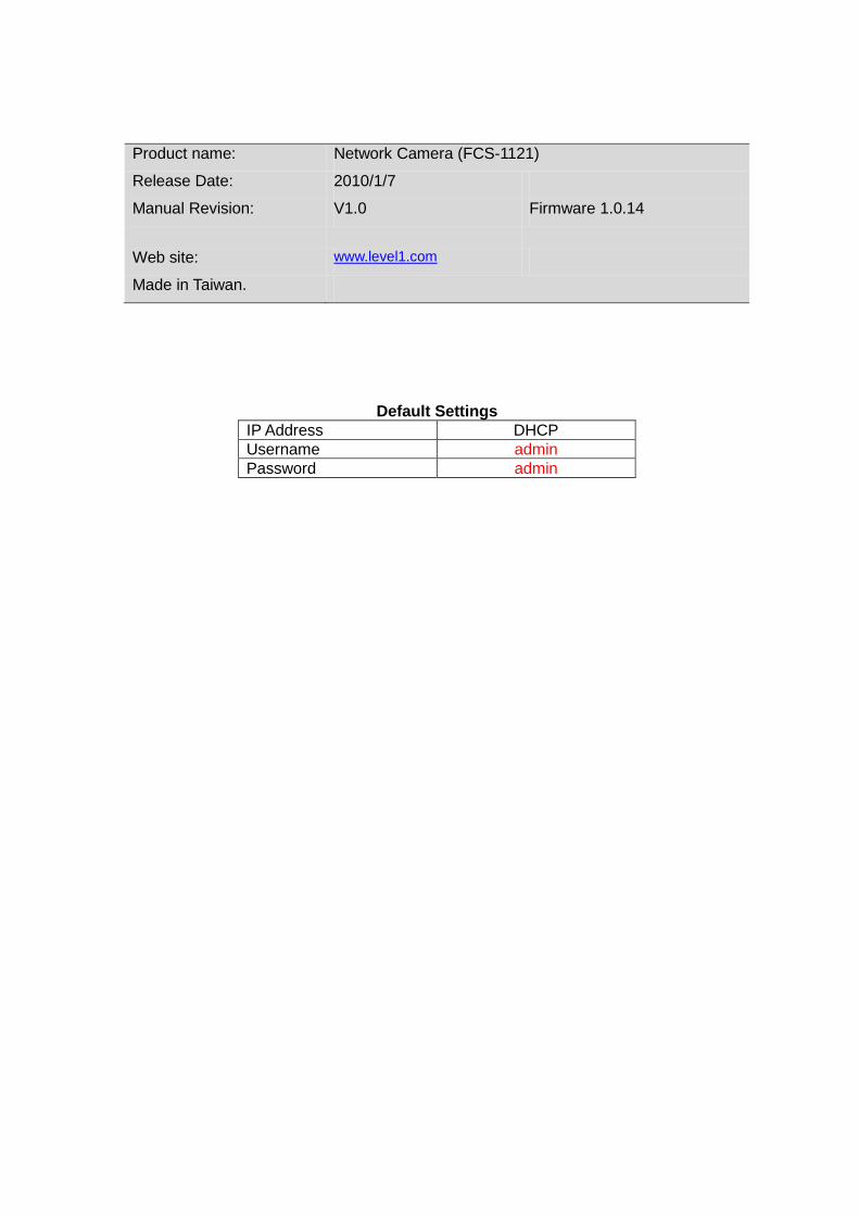
Product name: Network Camera (FCS-1121)
Release Date: 2010/1/7
Manual Revision: V1.0 Firmware 1.0.14
Web site: www.level1.com
Made in Taiwan.
Default Settings IP Address DHCP Username admin Password admin

0 0
Table of Contents Before You Use This Product ................................................................................. 1Fixed Dome Network Camera Overview .................................................................... 2Device Appearance Description ........................................................................... 4LED Behavior ................................................................................................... 5Installation ........................................................................................................ 8
Hardware installation ...................................................................................... 8System Requirements ................................................................................ 11Camera Connection ................................................................................... 12
Basic Connection (Without PoE) ................................................... 12 Power over Ethernet (PoE) Connection ........................................... 12
Adjust the Lens focus range and zoom viewing ............................................... 14How to adjust the view angle and focus range ................................................. 15Software Installation ..................................................................................... 16
Access to the Network Camera .......................................................................... 23Check Network Settings ................................................................................ 23Add Password to prevent Unauthorized Access .................................................... 23Authentication ............................................................................................ 24Installing plug-in ......................................................................................... 24
Live View ...................................................................................................... 25Configuration ................................................................................................. 27
Camera/Video/Audio .................................................................................. 27Camera .............................................................................................. 27Video ................................................................................................ 29Audio ................................................................................................ 32Multicast ............................................................................................ 33
Network ................................................................................................... 34IP Setting ........................................................................................... 34UPnP ................................................................................................. 35DDNS (dynamic domain name service) ........................................................ 36Easy Link ........................................................................................... 37HTTP/HTTPS ....................................................................................... 37
Event ...................................................................................................... 37Motion Detection ................................................................................. 38Notification setting ............................................................................... 39DI/DO ................................................................................................ 42
System .................................................................................................... 43System Log ........................................................................................ 43Date & Time Settings ............................................................................ 44Device Information ............................................................................... 45
Maintenance ............................................................................................. 46User Management ................................................................................ 46IP Filter .............................................................................................. 47Firmware Upgrade ................................................................................ 47Configuration ...................................................................................... 47Reset to default ................................................................................... 48Reboot .............................................................................................. 48
Technical specifications .............................................................. 錯誤! 尚未定義書籤。
1 1
Before You Use This Product The use of surveillance devices may be prohibited by law in your country. The Network
Camera is not only a high-performance web-ready camera but also can be part of a
flexible surveillance system. It is the user’s responsibility to ensure that the operation of
such devices is legal before installing this unit for its intended use.
It is important to first verify that all contents received are complete according to the list in
the "Package Contents" chapter.
Take notice of the warnings in “Quick installation guide” before the Network Camera is
installed, then carefully read and follow the instructions in the “Installation” chapter to
avoid damages due to faulty assembly and installation.
Package Contents Camera CD Manual/utility QIG Power Adapter

2 2
Fixed Dome Network Camera Overview Digital Data Communications introduces a full-featured 3-axis fixed dome network camera
FCS-3061. The Digital Data Communications ’s FCS-3061 designed for 24-hour security
surveillance indoor applications; it provided an excellent quality, wide-angle & vari-focal
lens, allowing you to have any wide view coverage you need. Users can view the live
motion image from anywhere by web browser via Internet. With the mega pixel
progressive sensor and built-in IR-cut filter / IR illuminator LEDs, FCS-3061 can provide
the high sensitivity and high image quality in both day and night environment.
Embedded with the high performance image sensor and CPU, FCS-3061 employs high
resolutions at 640 x 400 or 1280 x 800 for high-quality video and real-time viewing.
FCS-3061 also provides many advanced features, including MPEG-4 / MJPEG / H.264
Codec Compression and 802.3af compliant PoE.
In addition, the Digital Data Communications IP camera can transmit the video to portable
devices via other technology, for instance, WiMax, NAS, Digital Frame and power line.
Additionally, with the 3-axis mechanical design and “Easy Installation Wizard”, it offers the
end user a very flexible and easy installation for house, bank, office building and factory
applications.

3 3
4 4
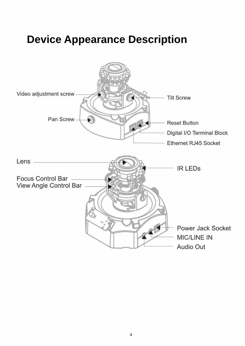
Device Appearance Description
5 5
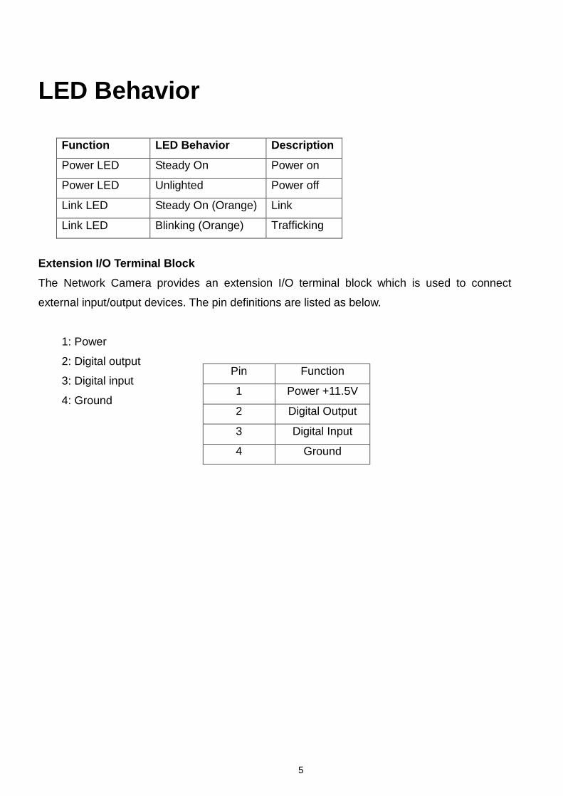
LED Behavior
Function LED Behavior Description
Power LED Steady On Power on
Power LED Unlighted Power off
Link LED Steady On (Orange) Link
Link LED Blinking (Orange) Trafficking
Extension I/O Terminal Block The Network Camera provides an extension I/O terminal block which is used to connect
external input/output devices. The pin definitions are listed as below.
1: Power
2: Digital output
3: Digital input
4: Ground
Pin Function
1 Power +11.5V
2 Digital Output
3 Digital Input
4 Ground

6 6
DI/DO Diagram
Hardware Reset
Reset Button

7 7
The reset button is used to reset the system or restore the factory default settings. Sometimes
resetting the system can return the camera to normal operation. If the problems remain after
reset, please restore the factory settings and install it again.
Reset: Please press and release the indented reset button within 1 second with paper clip or
thin object. Wait for the network camera to reboot.
Restore:
Please press and hold the reset button over 10 seconds then release. Please note
that all settings will be restored to factory default. Upon successful restore, the Power LED will
be green and Link LED blinking orange during normal operation.

8 8
Installation
Hardware installation First, please check your product package contains all the accessories listed in the
foregoing Package Contents. Depending on the user’s application and need, the
Ethernet cable should meet the specs of UTP Category 5 and not exceed 100 meters in
length.
1. Remove the dome cover from the camera device.
9 9
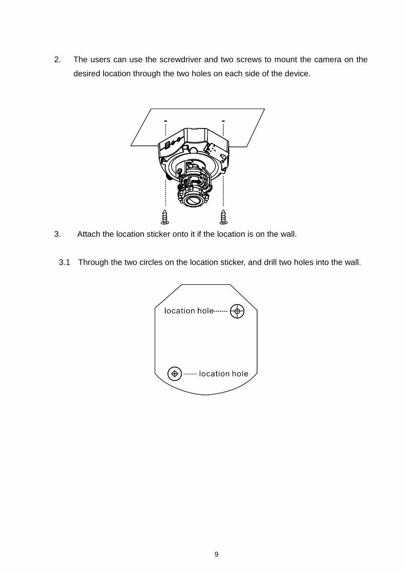
2. The users can use the screwdriver and two screws to mount the camera on the
desired location through the two holes on each side of the device.
3. Attach the location sticker onto it if the location is on the wall.
3.1 Through the two circles on the location sticker, and drill two holes into the wall.
10 10
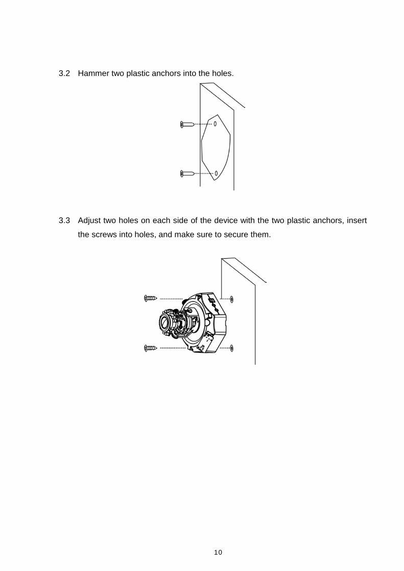
3.2 Hammer two plastic anchors into the holes.
3.3 Adjust two holes on each side of the device with the two plastic anchors, insert
the screws into holes, and make sure to secure them.

11 11
System Requirements
Microsoft Windows XP Home Edition SP2
Operating System:
Microsoft Windows XP Professional SP2
IBM PC/AT Compatible
Computer:
CPU:
Pentium 3GHz or faster
Memory:
1024 MB or more
Monitor:
1024 x 768 pixels or more, 24-bit True color or better
Network Interface:
10/100Mbps Network interface card must be installed
Web Browser:
Microsoft Internet Explorer 6.0 SP2
CD-ROM Drive:
It is necessary to read the operating instructions in the provided CD-ROM.
Adobe Reader:
It is necessary to read the operating instructions in the provided CD-ROM.
Audio function will not be working if a sound card is uninstalled on PC. Audio
may be interrupted depending on the network environment.

12 12
Camera Connection Basic Connection (Without PoE)
Connect the power adaptor to camera device.
Connect the camera to the Ethernet hub via RJ45 Ethernet cable.
Power over Ethernet (PoE) Connection Connect the camera to a PoE-enabled hub via single Ethernet cable.
Connect the camera to a non-PoE hub via PoE Injector.

13 13
Run the CD-ROM to install the Installation Wizard. For more information, please refer to “Software installation” for details.
Access to the Network Camera from the Internet. For more information, please refer to “Access to the Network Camera” for
details.
14 14
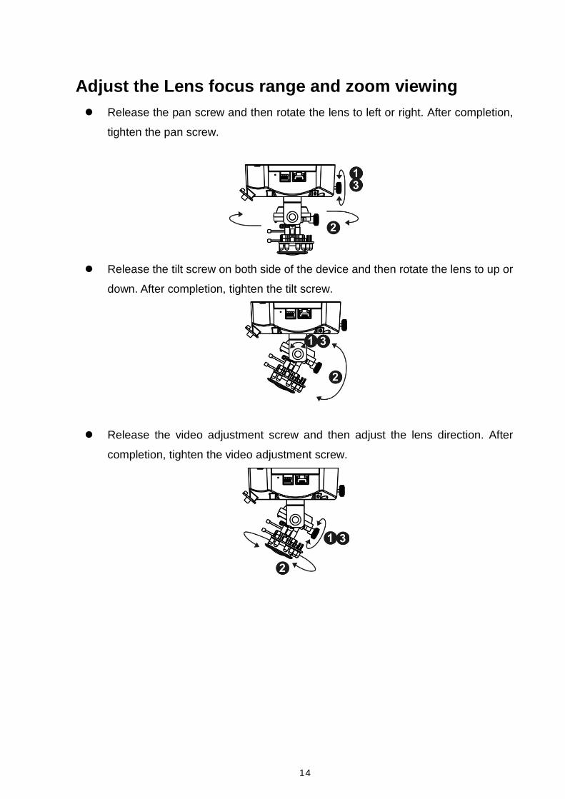
Adjust the Lens focus range and zoom viewing Release the pan screw and then rotate the lens to left or right. After completion,
tighten the pan screw.
Release the tilt screw on both side of the device and then rotate the lens to up or
down. After completion, tighten the tilt screw.
Release the video adjustment screw and then adjust the lens direction. After
completion, tighten the video adjustment screw.
15 15
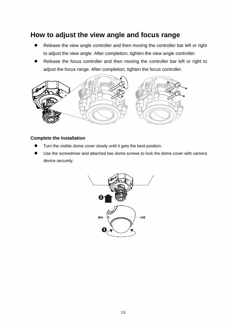
How to adjust the view angle and focus range Release the view angle controller and then moving the controller bar left or right
to adjust the view angle. After completion, tighten the view angle controller.
Release the focus controller and then moving the controller bar left or right to
adjust the focus range. After completion, tighten the focus controller.
Complete the Installation Turn the visible dome cover slowly until it gets the best position. Use the screwdriver and attached two dome screws to lock the dome cover with camera
device securely.
16
Software Installation
In this manual, "User" refers to whoever has access to the Network Camera, and
"Administrator" refers to the person who can configure the Network Camera and grant
user access to the camera.
After hardware connection checking, the users can run the Installation Wizard program
included in the product CDROM to automatically search for the Network Camera in the
Intranet. There may be many Network Cameras in the local network. Users can
differentiate the Network Cameras with the serial number. The serial number is printed on the labels on the carton and the bottom of the Network Camera body.
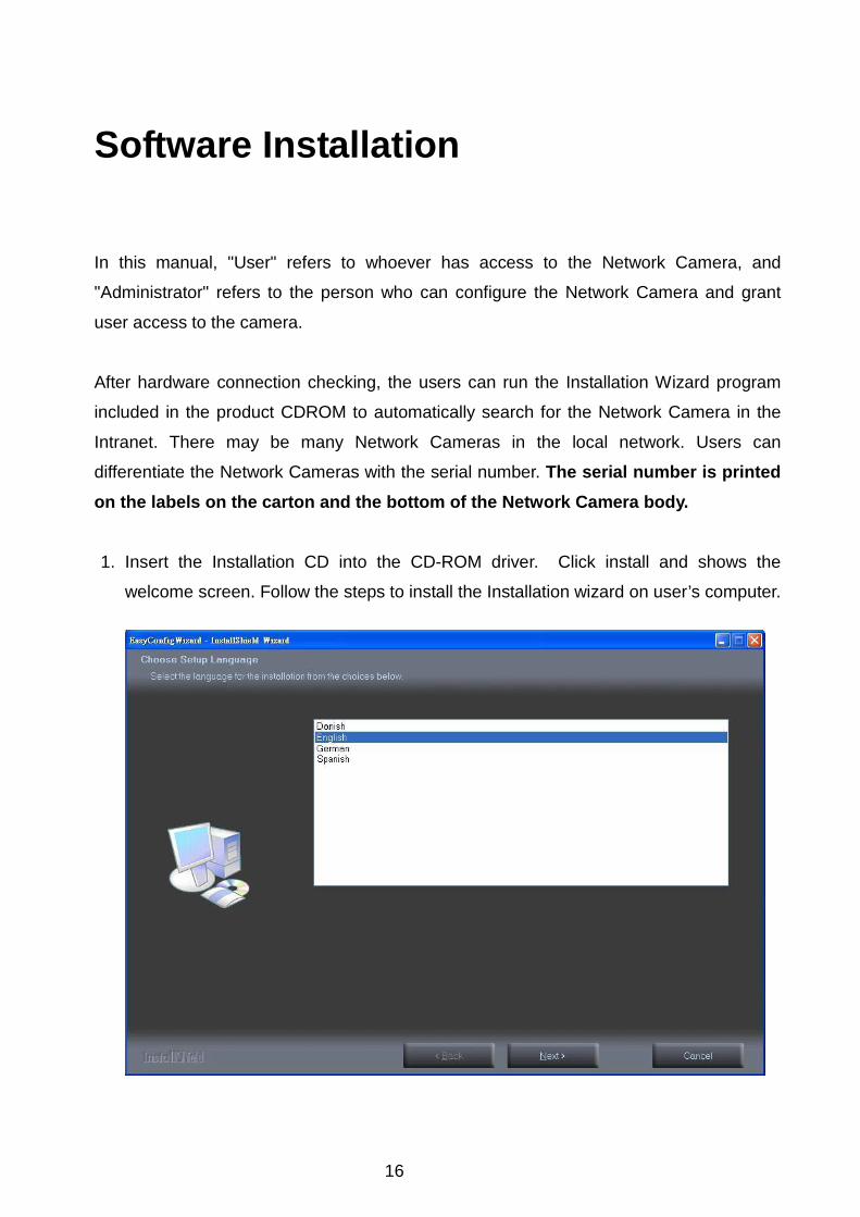
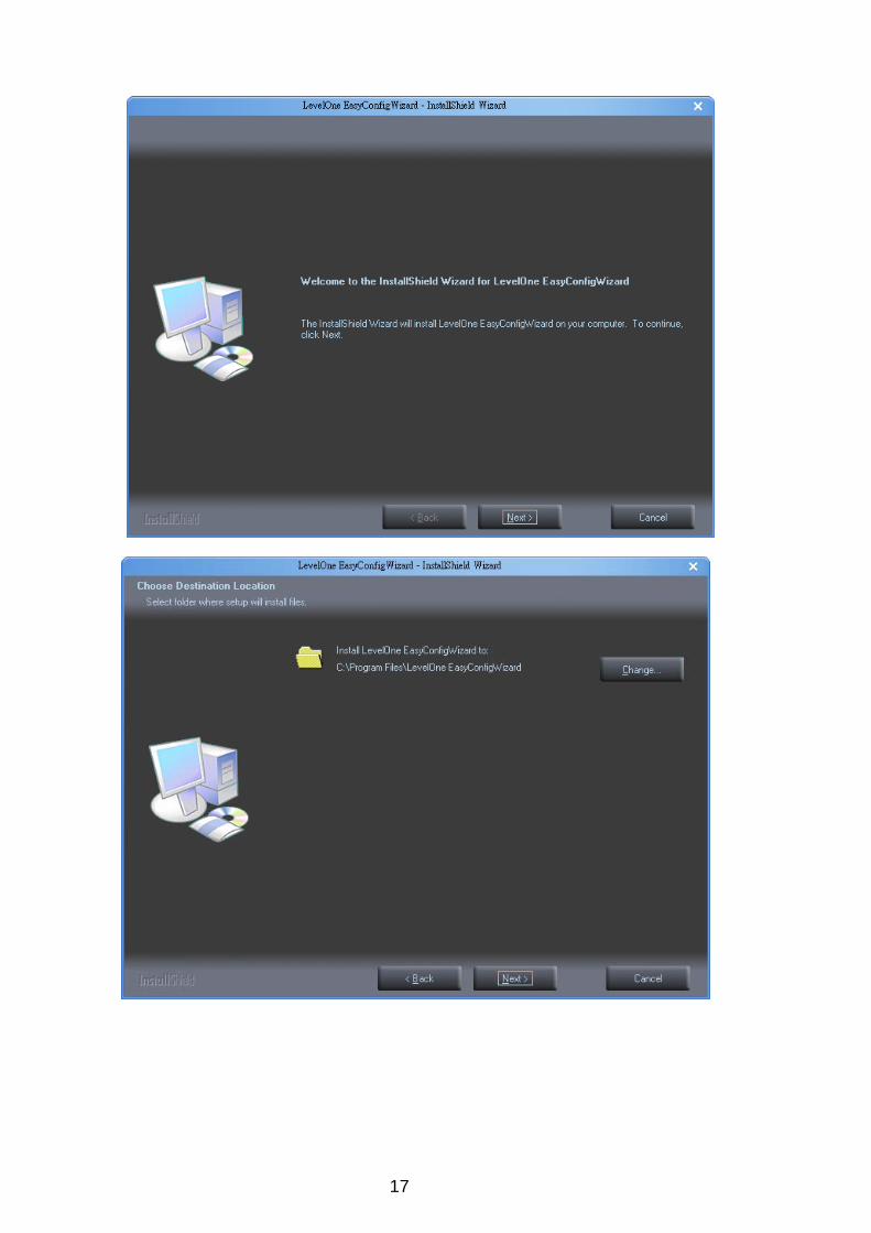
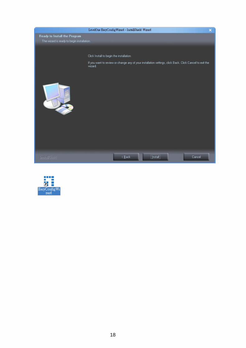
1. Insert the Installation CD into the CD-ROM driver. Click install and shows the
welcome screen. Follow the steps to install the Installation wizard on user’s computer.
17
18
19
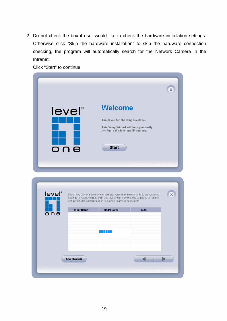
2. Do not check the box if user would like to check the hardware installation settings.
Otherwise click “Skip the hardware installation” to skip the hardware connection
checking, the program will automatically search for the Network Camera in the
Intranet.
Click “Start” to continue.
20
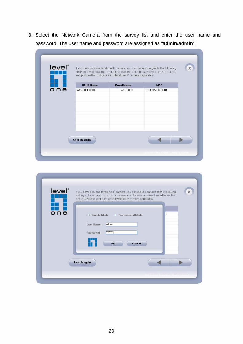
3. Select the Network Camera from the survey list and enter the user name and
password. The user name and password are assigned as “admin/admin”.

21
4. Setting the Network Camera IP address
User can either select simple mode or professional mode for network camera
IP setting. If simple mode is selected, the easy configuration program will set
up the connection automatically. If professional mode is selected, the user will
need to configure the IP manually, The DHCP setting is recommended. If user
wants to set IP address manually, please refer to the product user manual.
22
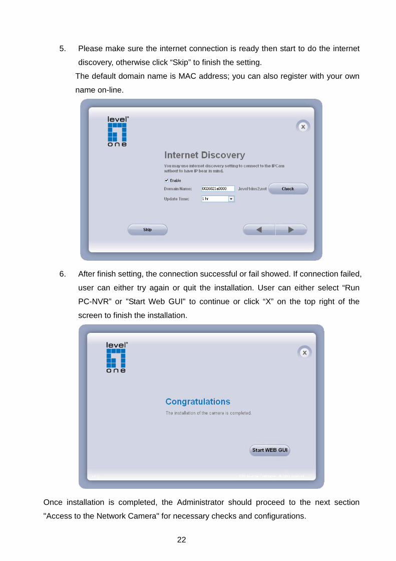
5. Please make sure the internet connection is ready then start to do the internet
discovery, otherwise click “Skip” to finish the setting.
The default domain name is MAC address; you can also register with your own
name on-line.
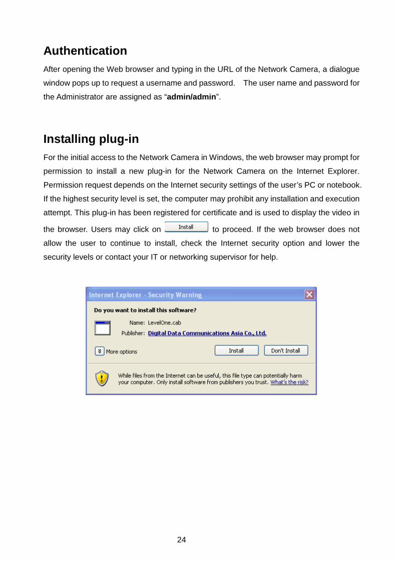
6. After finish setting, the connection successful or fail showed. If connection failed,
user can either try again or quit the installation. User can either select “Run
PC-NVR” or "Start Web GUI" to continue or click “X” on the top right of the
screen to finish the installation.
Once installation is completed, the Administrator should proceed to the next section
"Access to the Network Camera" for necessary checks and configurations.

23
Access to the Network Camera Check Network Settings The Network Camera can be connected either before or immediately after software
installation onto the Local Area Network. The Administrator should complete the network
settings on the configuration page, including the correct subnet mask and IP address of
gateway and DNS. Ask your network administrator or Internet service provider for the
detail information.
Add Password to prevent Unauthorized Access The Administrator should immediately implement a new password as a matter of prudent security practice. The user name and password for the Administrator are
assigned as “admin/admin”. Once the Administrator’s password is saved, the Network
Camera will ask for the user’s name and password before each access. The Administrator
can set up a maximum of ten (10) user accounts. Each user can access the Network
Camera except to perform system configuration. Once the password is changed, the
browser will display an authentication window to ask for the new password. Once the password is set, there is no provision to recover the Administrator’s password. The only option is to restore to the original factory default settings.
24
Authentication After opening the Web browser and typing in the URL of the Network Camera, a dialogue
window pops up to request a username and password. The user name and password for
the Administrator are assigned as “admin/admin”.
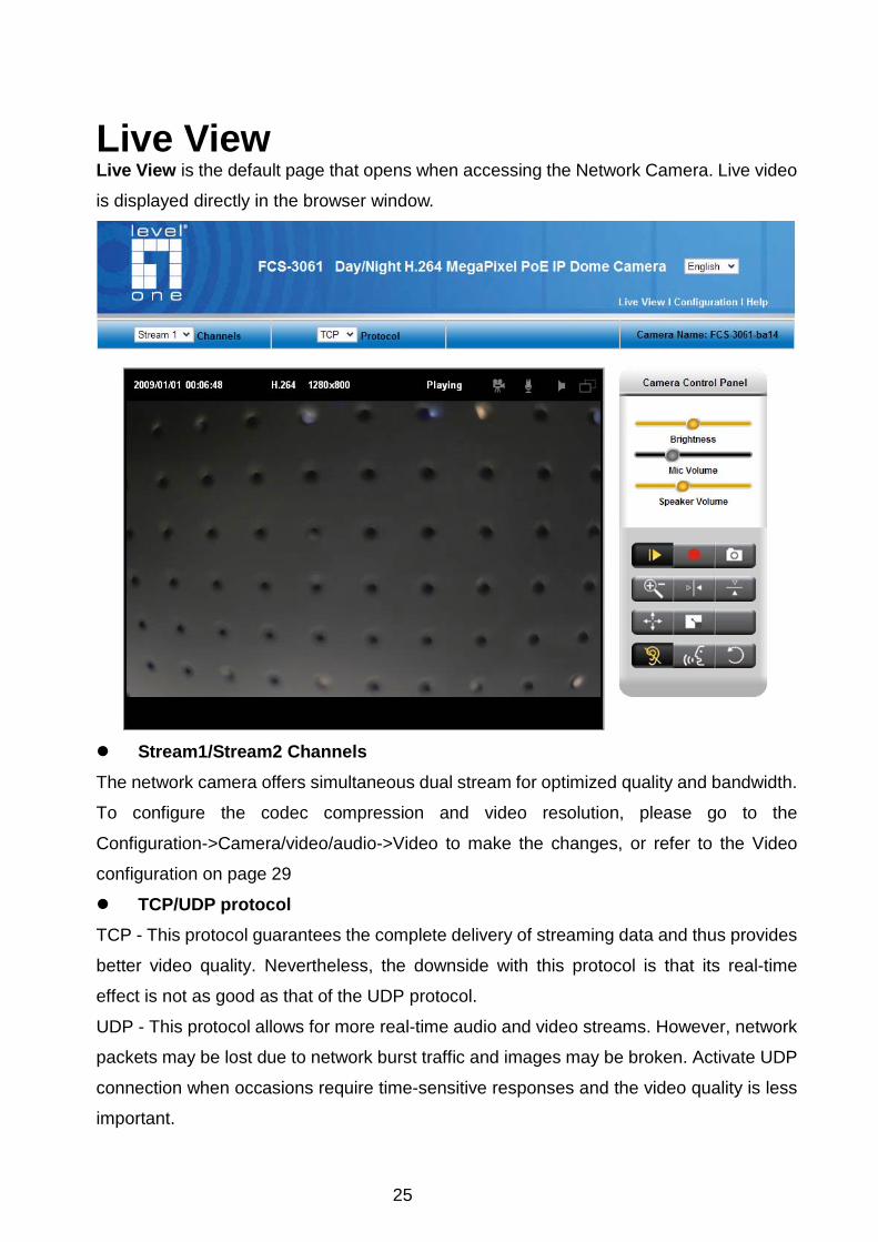
Installing plug-in For the initial access to the Network Camera in Windows, the web browser may prompt for
permission to install a new plug-in for the Network Camera on the Internet Explorer.
Permission request depends on the Internet security settings of the user’s PC or notebook.
If the highest security level is set, the computer may prohibit any installation and execution
attempt. This plug-in has been registered for certificate and is used to display the video in
the browser. Users may click on to proceed. If the web browser does not
allow the user to continue to install, check the Internet security option and lower the
security levels or contact your IT or networking supervisor for help.
25
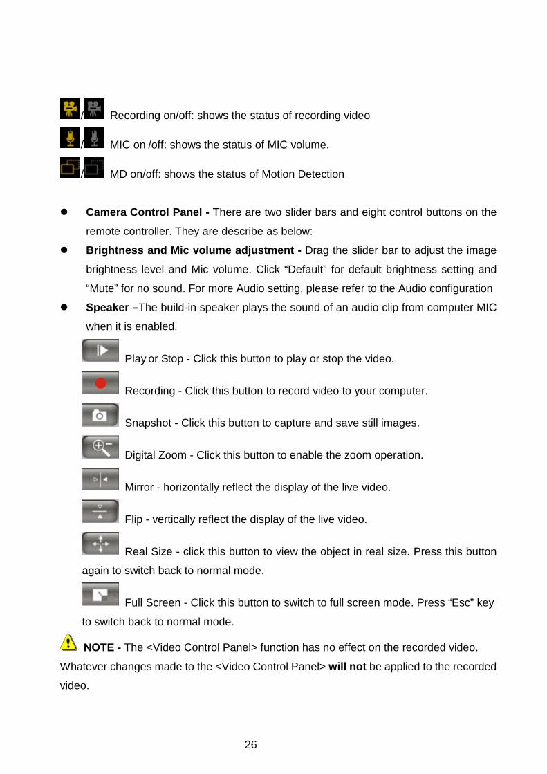
Live View Live View is the default page that opens when accessing the Network Camera. Live video
is displayed directly in the browser window.
Stream1/Stream2 Channels The network camera offers simultaneous dual stream for optimized quality and bandwidth.
To configure the codec compression and video resolution, please go to the
Configuration->Camera/video/audio->Video to make the changes, or refer to the Video
configuration on page 29
TCP/UDP protocol TCP - This protocol guarantees the complete delivery of streaming data and thus provides
better video quality. Nevertheless, the downside with this protocol is that its real-time
effect is not as good as that of the UDP protocol.
UDP - This protocol allows for more real-time audio and video streams. However, network
packets may be lost due to network burst traffic and images may be broken. Activate UDP
connection when occasions require time-sensitive responses and the video quality is less
important.
26
/ Recording on/off: shows the status of recording video
/ MIC on /off: shows the status of MIC volume.
/ MD on/off: shows the status of Motion Detection
Camera Control Panel - There are two slider bars and eight control buttons on the
remote controller. They are describe as below: Brightness and Mic volume adjustment - Drag the slider bar to adjust the image
brightness level and Mic volume. Click “Default” for default brightness setting and
“Mute” for no sound. For more Audio setting, please refer to the Audio configuration
Speaker –The build-in speaker plays the sound of an audio clip from computer MIC
when it is enabled.
Play or Stop - Click this button to play or stop the video.
Recording - Click this button to record video to your computer.
Snapshot - Click this button to capture and save still images.
Digital Zoom - Click this button to enable the zoom operation.
Mirror - horizontally reflect the display of the live video.
Flip - vertically reflect the display of the live video.
Real Size - click this button to view the object in real size. Press this button
again to switch back to normal mode.
Full Screen - Click this button to switch to full screen mode. Press “Esc” key
to switch back to normal mode.
NOTE - The <Video Control Panel> function has no effect on the recorded video.
Whatever changes made to the <Video Control Panel> will not be applied to the recorded
video.
27
Configuration Camera/Video/Audio Camera
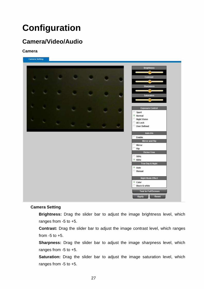
Camera Setting
Brightness: Drag the slider bar to adjust the image brightness level, which
ranges from -5 to +5.
Contrast: Drag the slider bar to adjust the image contrast level, which ranges
from -5 to +5.
Sharpness: Drag the slider bar to adjust the image sharpness level, which
ranges from -5 to +5.
Saturation: Drag the slider bar to adjust the image saturation level, which
ranges from -5 to +5.
28
Night Vision IR CUT: the Network Camera switches off the IR cut filter at all times for the
sensor to accept the infrared light, thus helps improve low light sensitivity.
IR LED: The user can select this option to turn on/off the IR.
Auto: The Network Camera automatically removes the filter by judging the level
of ambient light.
Shutter Speed – Only affected in low lighting conditions Motion – enable this function to have normal motion, but slight blur image. Low Noise – enable this function to have sharper image, but slight tardy motion. Environment - User can look for a place that best suits your needs, either outdoor or
indoor.
Flicker-Free - While flicker-free technology eliminates the problem of flicker, it can cause slight judder on fast moving images or blurring problems; fast
scrolling text for example may blur.
NOTE - The "Environment" setting adjusts the sampling rate of the camera sensor to
achieve Flicker-free effect on the video.
The sampling rate, however, may not work best with the frame rate chosen in the "Video"
setting.
For best recording experience, configure your IP camera to one of the following frame
rates based on the Environment used:
Environment / Flicker-Free Frame Rate ------------------------------------ ----------------------------------
Outdoor 25, 10, 7, 5, 3, 2
Indoor (50/60 Hz ) 20, 10, 7, 5, 3, 2
IRIS Auto Iris lens - Select when the auto Iris lens is installed. Manual Iris lens is
the default lens. Mirror and Flip
Mirror - Enable to horizontally reflect the display of the live video.
Flip - Enable to vertically reflect the display of the live video.
Click Apply or Reset to take effect.
29
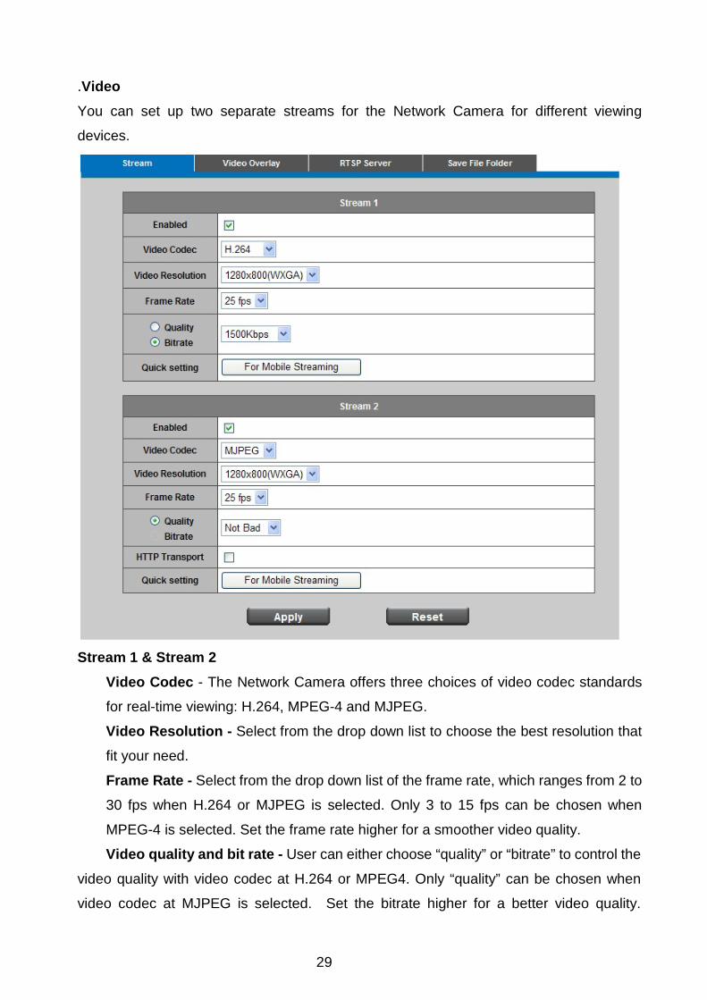
.Video You can set up two separate streams for the Network Camera for different viewing
devices.
Stream 1 & Stream 2
Video Codec - The Network Camera offers three choices of video codec standards
for real-time viewing: H.264, MPEG-4 and MJPEG.
Video Resolution - Select from the drop down list to choose the best resolution that
fit your need.
Frame Rate - Select from the drop down list of the frame rate, which ranges from 2 to
30 fps when H.264 or MJPEG is selected. Only 3 to 15 fps can be chosen when
MPEG-4 is selected. Set the frame rate higher for a smoother video quality.
Video quality and bit rate - User can either choose “quality” or “bitrate” to control the
video quality with video codec at H.264 or MPEG4. Only “quality” can be chosen when
video codec at MJPEG is selected. Set the bitrate higher for a better video quality.
30
However, high bitrate may cost high network bandwidth resources.
The video qualities are selectable at the following settings: SoSo, OK, Not Bad,
Medium, Standard, and Good.
HTTP Transport – Enable to use HTTP protocol for video/audio communication.
Click Apply or Reset to take effect.
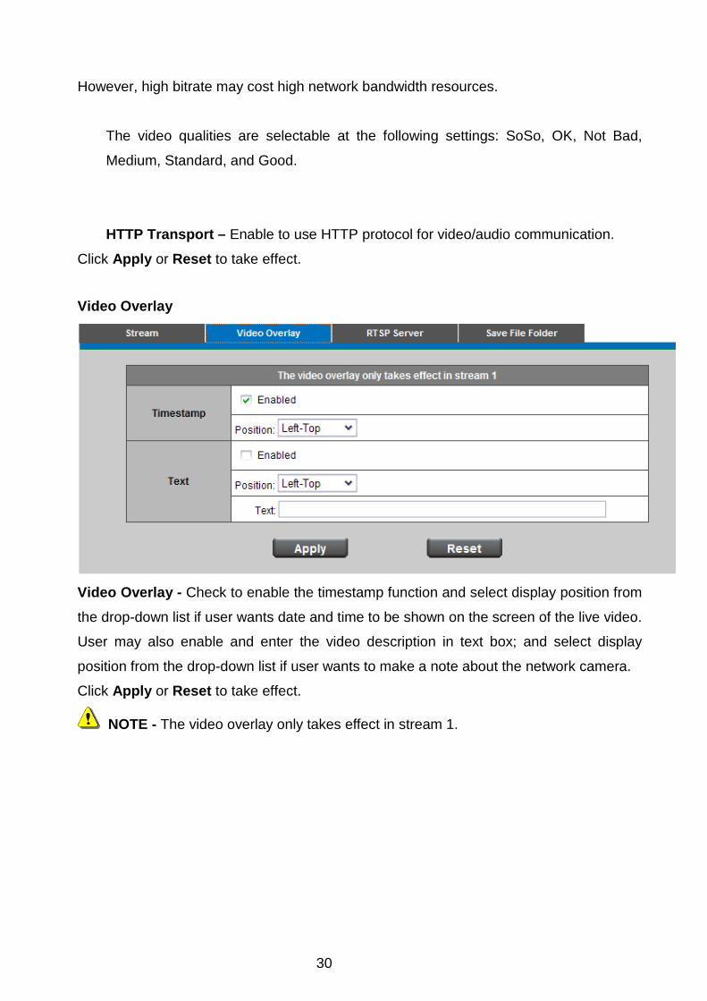
Video Overlay
Video Overlay - Check to enable the timestamp function and select display position from
the drop-down list if user wants date and time to be shown on the screen of the live video.
User may also enable and enter the video description in text box; and select display
position from the drop-down list if user wants to make a note about the network camera.
Click Apply or Reset to take effect.
NOTE - The video overlay only takes effect in stream 1.
31
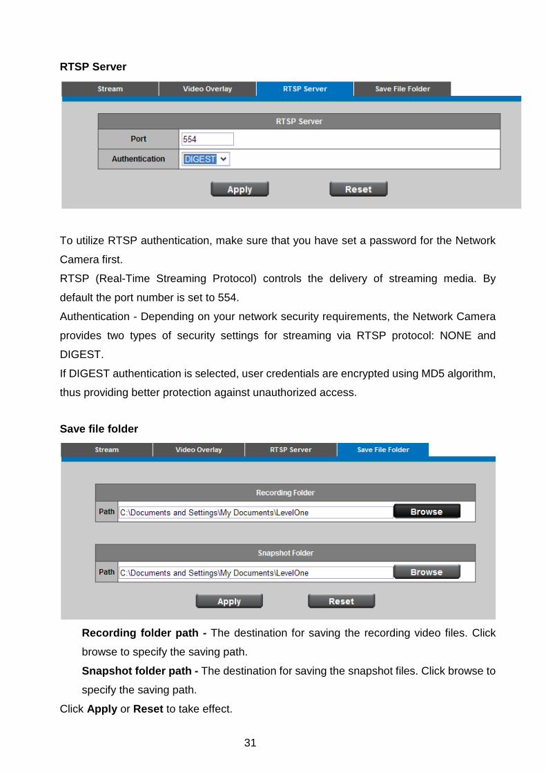
RTSP Server
To utilize RTSP authentication, make sure that you have set a password for the Network
Camera first.
RTSP (Real-Time Streaming Protocol) controls the delivery of streaming media. By
default the port number is set to 554.
Authentication - Depending on your network security requirements, the Network Camera
provides two types of security settings for streaming via RTSP protocol: NONE and
DIGEST.
If DIGEST authentication is selected, user credentials are encrypted using MD5 algorithm,
thus providing better protection against unauthorized access.
Save file folder
Recording folder path - The destination for saving the recording video files. Click
browse to specify the saving path.
Snapshot folder path - The destination for saving the snapshot files. Click browse to
specify the saving path.
Click Apply or Reset to take effect.

32
Audio
You can set up two separate streams for the Network Camera for different viewing
devices. User can either enable or disable the audio function. If audio enable is selected,
select the Audio codec from the drop down list.
Advanced
Echo cancellation Enabled: Enable to avoid an echo.
Click Apply or Reset to take effect.
33
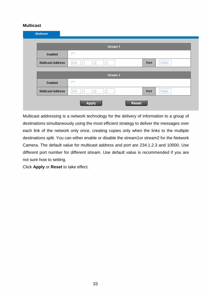
Multicast
Multicast addressing is a network technology for the delivery of information to a group of
destinations simultaneously using the most efficient strategy to deliver the messages over
each link of the network only once, creating copies only when the links to the multiple
destinations split. You can either enable or disable the stream1or stream2 for the Network
Camera. The default value for multicast address and port are 234.1.2.3 and 10000. Use
different port number for different stream. Use default value is recommended if you are
not sure how to setting.
Click Apply or Reset to take effect.

34
Network IP Setting This section explains how to configure wired network connection for the Network Camera.
There are several ways to setup the Network Camera over the Internet. The first way is to
obtain an available dynamic IP address assigned by a DHCP server. The second way is to
utilize a static IP. The third way is to use PPPoE.
35
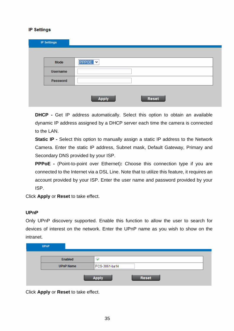
DHCP - Get IP address automatically. Select this option to obtain an available
dynamic IP address assigned by a DHCP server each time the camera is connected
to the LAN.
Static IP - Select this option to manually assign a static IP address to the Network
Camera. Enter the static IP address, Subnet mask, Default Gateway, Primary and
Secondary DNS provided by your ISP.
PPPoE - (Point-to-point over Ethernet): Choose this connection type if you are
connected to the Internet via a DSL Line. Note that to utilize this feature, it requires an
account provided by your ISP. Enter the user name and password provided by your
ISP.
Click Apply or Reset to take effect.
UPnP Only UPnP discovery supported. Enable this function to allow the user to search for
devices of interest on the network. Enter the UPnP name as you wish to show on the
intranet.
Click Apply or Reset to take effect.

36
DDNS (dynamic domain name service)
DynDNS - Enable the DDNS service allows your Network Camera, especially when
assigned with a dynamic IP address, to have a fixed host and domain name. Note that
before utilizing this function; please apply a dynamic domain account first. Enter the
username, password and hostname when enabled the DDNS.
Click Apply or Reset to take effect.
TZO
TZO - TZO is one kind of the DDNS providers. User can refer to the TZO.com: visit
http://www.tzo.com/ to apply a dynamic domain account when selecting this DDNS
provider. Enter the e-mail address, password and domain name when enabled the TZO.
Click Apply or Reset to take effect.
37
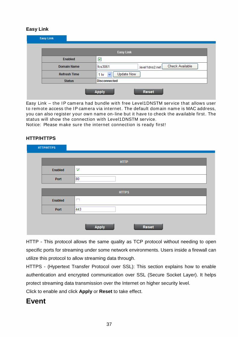
Easy Link
Easy Link – the IP camera had bundle with free Level1DNSTM service that allows user to remote access the IP camera via internet. The default domain name is MAC address, you can also register your own name on-line but it have to check the available first. The status will show the connection with Level1DNSTM service. Notice: Please make sure the internet connection is ready first! HTTP/HTTPS
HTTP - This protocol allows the same quality as TCP protocol without needing to open
specific ports for streaming under some network environments. Users inside a firewall can
utilize this protocol to allow streaming data through.
HTTPS - (Hypertext Transfer Protocol over SSL): This section explains how to enable
authentication and encrypted communication over SSL (Secure Socket Layer). It helps
protect streaming data transmission over the Internet on higher security level.
Click to enable and click Apply or Reset to take effect.
Event
38
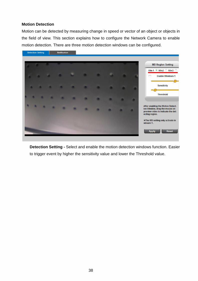
Motion Detection
Motion can be detected by measuring change in speed or vector of an object or objects in
the field of view. This section explains how to configure the Network Camera to enable
motion detection. There are three motion detection windows can be configured.
Detection Setting - Select and enable the motion detection windows function. Easier
to trigger event by higher the sensitivity value and lower the Threshold value.
39
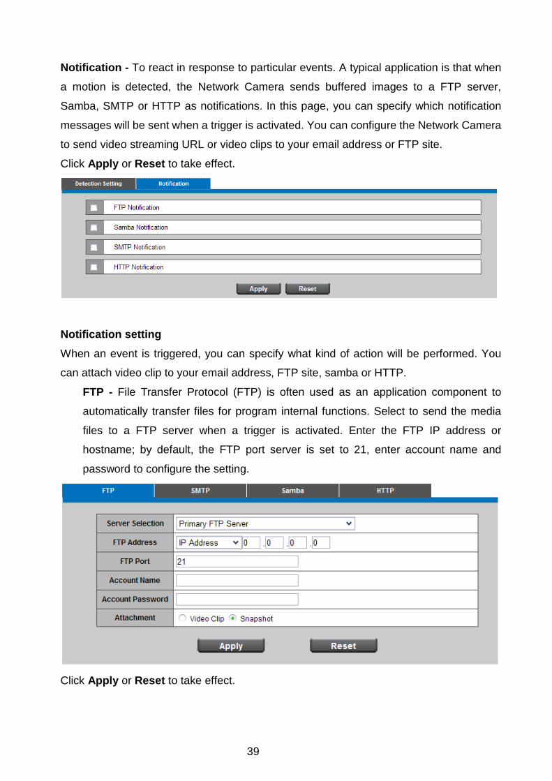
Notification - To react in response to particular events. A typical application is that when
a motion is detected, the Network Camera sends buffered images to a FTP server,
Samba, SMTP or HTTP as notifications. In this page, you can specify which notification
messages will be sent when a trigger is activated. You can configure the Network Camera
to send video streaming URL or video clips to your email address or FTP site.
Click Apply or Reset to take effect.
Notification setting When an event is triggered, you can specify what kind of action will be performed. You
can attach video clip to your email address, FTP site, samba or HTTP.
FTP - File Transfer Protocol (FTP) is often used as an application component to
automatically transfer files for program internal functions. Select to send the media
files to a FTP server when a trigger is activated. Enter the FTP IP address or
hostname; by default, the FTP port server is set to 21, enter account name and
password to configure the setting.
Click Apply or Reset to take effect.

40
SMTP - Select to send the media files via Email when a trigger is activated.
From - Enter the email address of the sender.
To - Enter the email address of the recipient. Many recipients are separated by
commas.
My name - The title shown in the email.
Subject - Enter the subject of the email.
Attached - There are two choices of media types available: video streaming URL and
video clip.
SMTP Server and port number - Enter the server host name and port number of the
email server.
Authentication - Select the authentication type from the drop-down list.
Email Account - Enter the user name of the email account if necessary.
Email Password - Enter the password of the email account if necessary.
Click Apply or Reset to take effect.
41
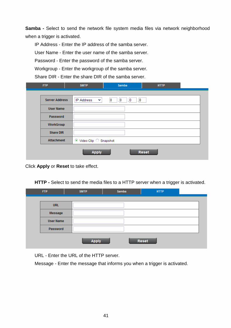
Samba - Select to send the network file system media files via network neighborhood
when a trigger is activated.
IP Address - Enter the IP address of the samba server.
User Name - Enter the user name of the samba server.
Password - Enter the password of the samba server.
Workgroup - Enter the workgroup of the samba server.
Share DIR - Enter the share DIR of the samba server.
Click Apply or Reset to take effect.
HTTP - Select to send the media files to a HTTP server when a trigger is activated.
URL - Enter the URL of the HTTP server.
Message - Enter the message that informs you when a trigger is activated.

42
DI/DO
Digital input - Select High or Low to define normal status of the digital input. The Network
Camera will report the current status.
Digital output - Select Grounded or Open and enter the duration to define normal status
of the digital output.

43
System System Log Log - To send a system log to the network camera when a trigger is activated.
This page displays the system’s log in chronological order. The system log is stored in the
Network Camera’s buffer area and will be overwritten when reaching a certain amount.
Click Retrieve to retrieve the log, or click Save to file to save the file in the specify
location.
44
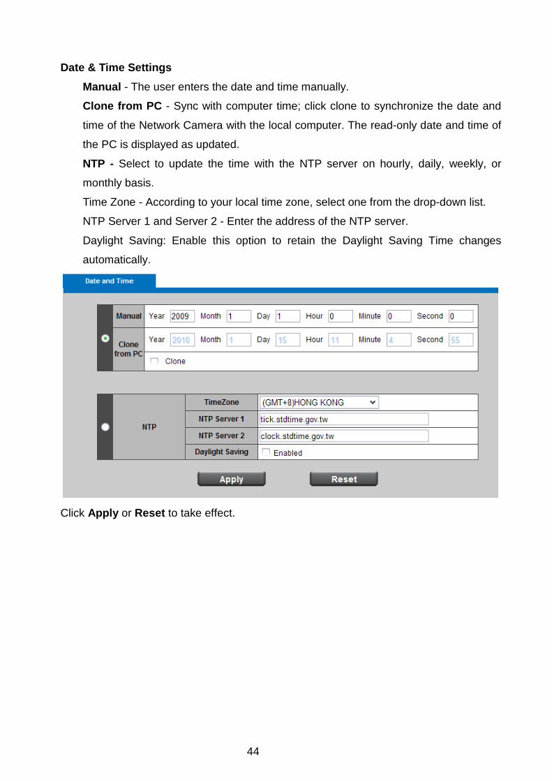
Date & Time Settings Manual - The user enters the date and time manually.
Clone from PC - Sync with computer time; click clone to synchronize the date and
time of the Network Camera with the local computer. The read-only date and time of
the PC is displayed as updated.
NTP - Select to update the time with the NTP server on hourly, daily, weekly, or
monthly basis.
Time Zone - According to your local time zone, select one from the drop-down list.
NTP Server 1 and Server 2 - Enter the address of the NTP server.
Daylight Saving: Enable this option to retain the Daylight Saving Time changes
automatically.
Click Apply or Reset to take effect.
45
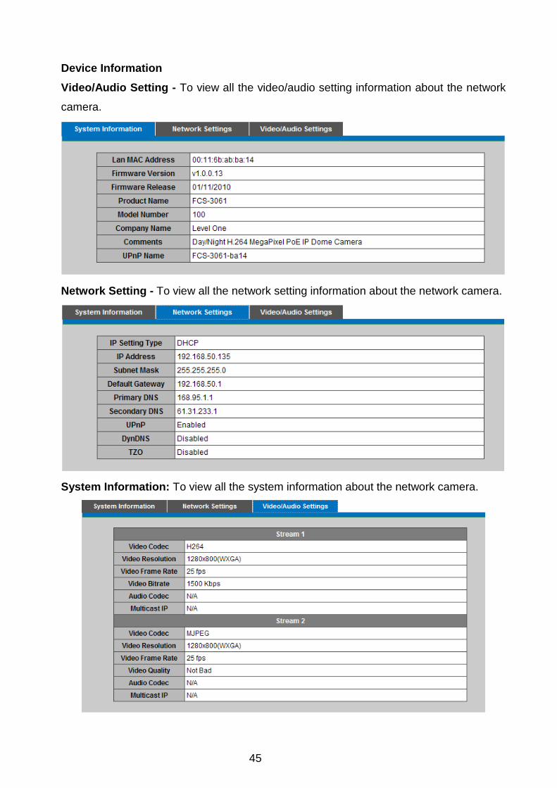
Device Information
Video/Audio Setting - To view all the video/audio setting information about the network
camera.
Network Setting - To view all the network setting information about the network camera.
System Information: To view all the system information about the network camera.

46
Maintenance User Management This section explains how to enable password protection and create multiple accounts.
Privilege Setting - Enter the new user’s name and password. Select the privilege
for new user account. Click Add to take effect. The administrator account name is
“admin”, which is permanent and can not be deleted.
Access rights are sorted as following (Viewer, Administrator and Remote Viewer).
Only administrators can access the Configuration page. Viewers can access the main
page for live viewing only. The privilege of Remote Viewer is same as viewer except
TCP protocol can only be selected for live viewing page. Administrators can add up
to 10 user accounts. Administrator also can change user’s access rights or delete
user accounts. Select an existing account to modify and make necessary changes;
then click Update or Delete to take effect.
47
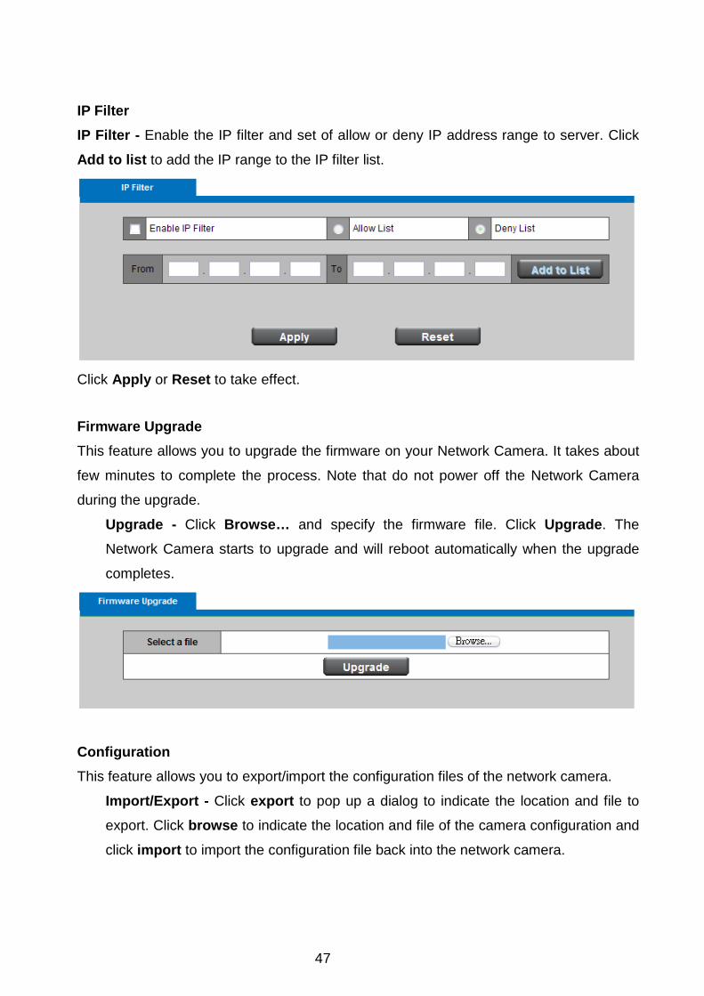
IP Filter IP Filter - Enable the IP filter and set of allow or deny IP address range to server. Click
Add to list to add the IP range to the IP filter list.
Click Apply or Reset to take effect.
Firmware Upgrade
This feature allows you to upgrade the firmware on your Network Camera. It takes about
few minutes to complete the process. Note that do not power off the Network Camera
during the upgrade.
Upgrade - Click Browse… and specify the firmware file. Click Upgrade. The
Network Camera starts to upgrade and will reboot automatically when the upgrade
completes.
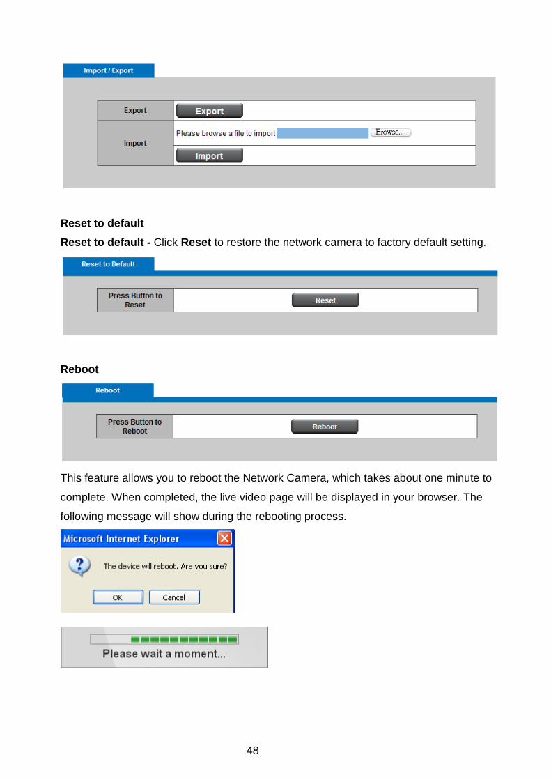
Configuration This feature allows you to export/import the configuration files of the network camera.
Import/Export - Click export to pop up a dialog to indicate the location and file to
export. Click browse to indicate the location and file of the camera configuration and
click import to import the configuration file back into the network camera.
48
Reset to default
Reset to default - Click Reset to restore the network camera to factory default setting.
Reboot
This feature allows you to reboot the Network Camera, which takes about one minute to
complete. When completed, the live video page will be displayed in your browser. The
following message will show during the rebooting process.