Embed Size (px)
Citation preview
ULTRASONIC TRANSMITTER
Amanda Hellberg, Brandon Ravenscroft,
Jonathan Owen, and Kai Gustafson
TEAM B-CDR
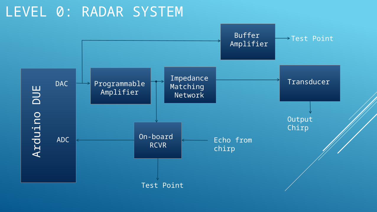
LEVEL 0: RADAR SYSTEM
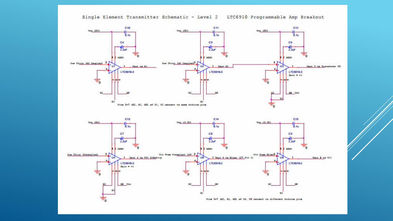
Programmable Amplifier
Buffer Amplifier
ImpedanceMatching Network
Transducer
On-board RCVR
Ard
uin
o D
UE
DAC
ADC
Test Point
Echo from chirp
Output Chirp
Test Point
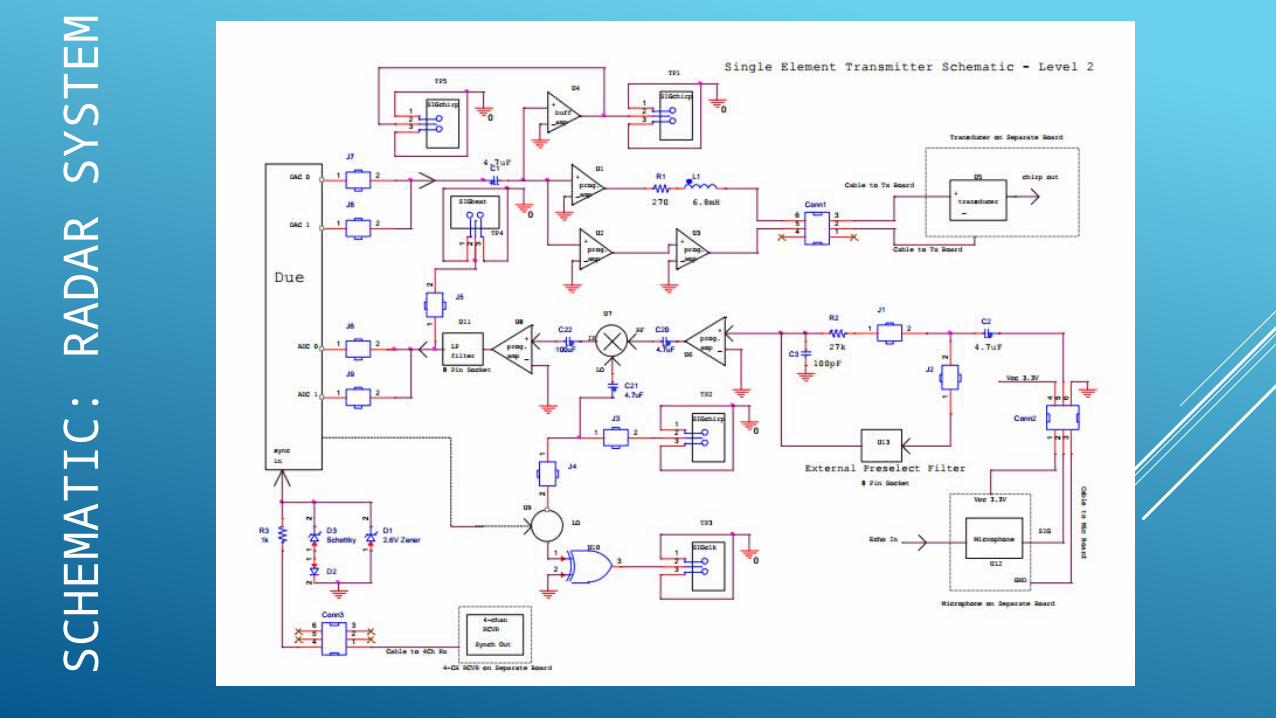
SC
HEM
ATIC
: R
AD
AR
SYSTEM
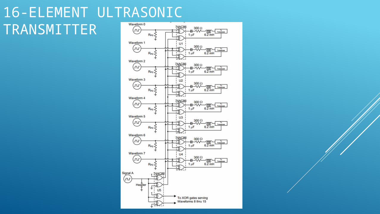
16-ELEMENT ULTRASONIC TRANSMITTER
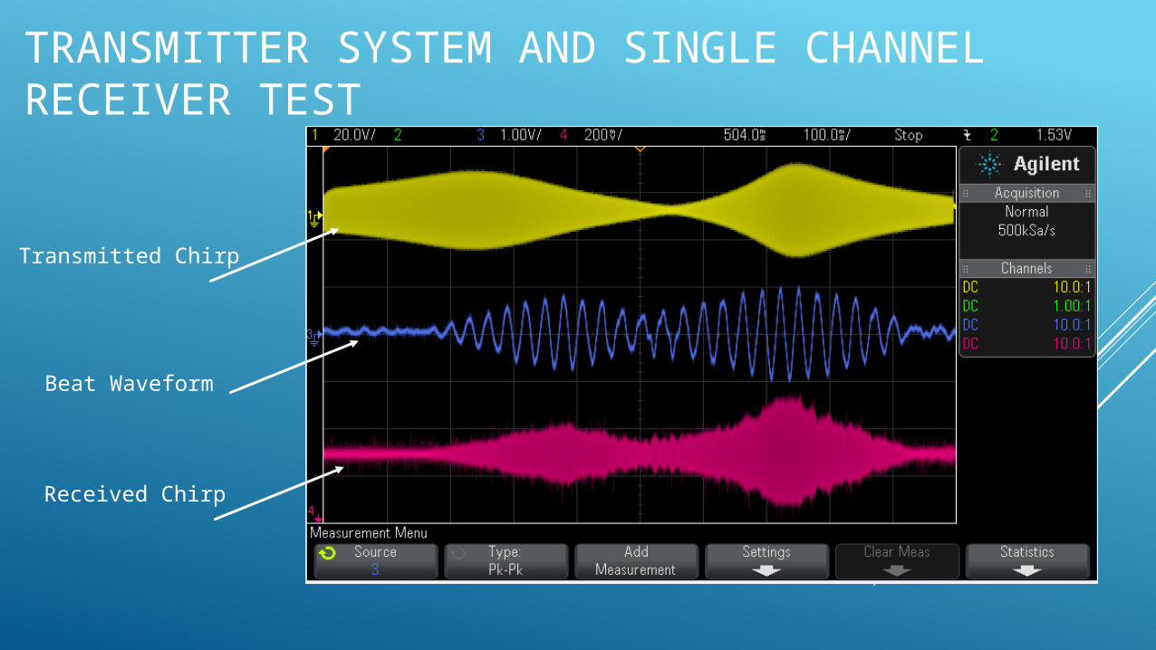
TRANSMITTER SYSTEM AND SINGLE CHANNEL RECEIVER TEST
Transmitted Chirp
Received Chirp
Beat Waveform
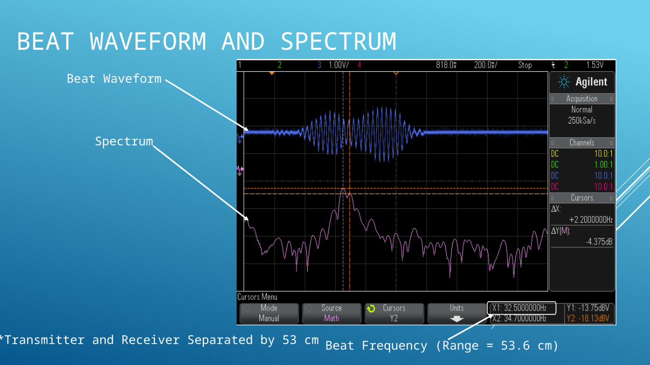
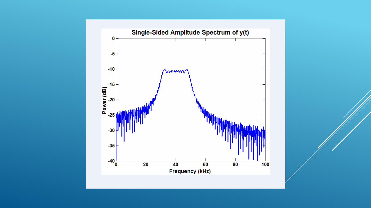
BEAT WAVEFORM AND SPECTRUMBeat Waveform
Spectrum
Beat Frequency (Range = 53.6 cm)*Transmitter and Receiver Separated by 53 cm
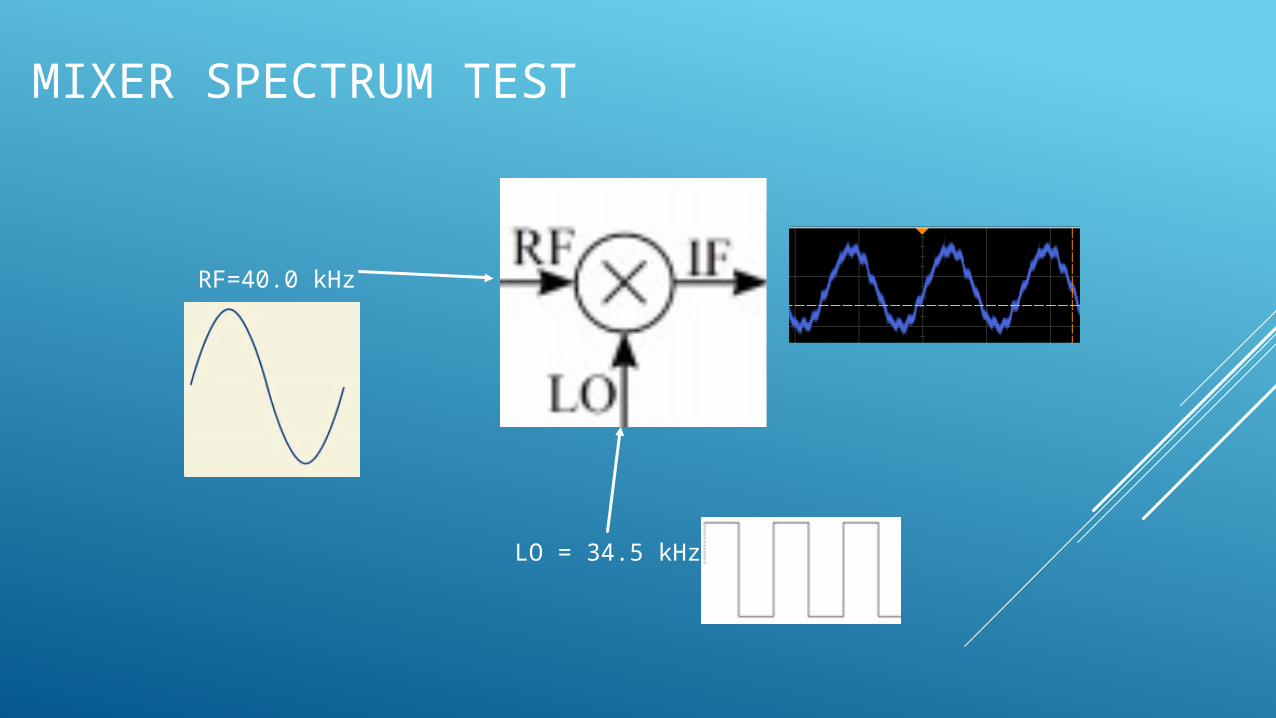
MIXER SPECTRUM TEST
LO = 34.5 kHz
RF=40.0 kHz
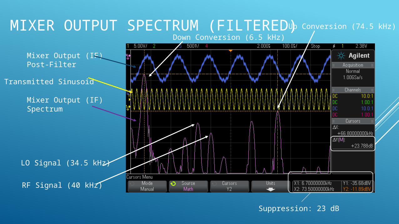
MIXER OUTPUT SPECTRUM (FILTERED)
Mixer Output (IF)Post-Filter
Transmitted Sinusoid
Mixer Output (IF)Spectrum
Down Conversion (6.5 kHz)
Up Conversion (74.5 kHz)
LO Signal (34.5 kHz)
RF Signal (40 kHz)
Suppression: 23 dB
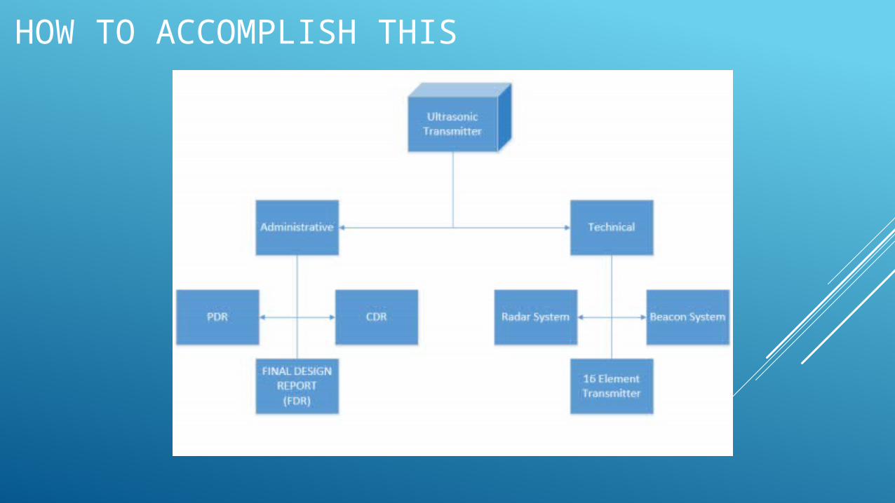
HOW TO ACCOMPLISH THIS
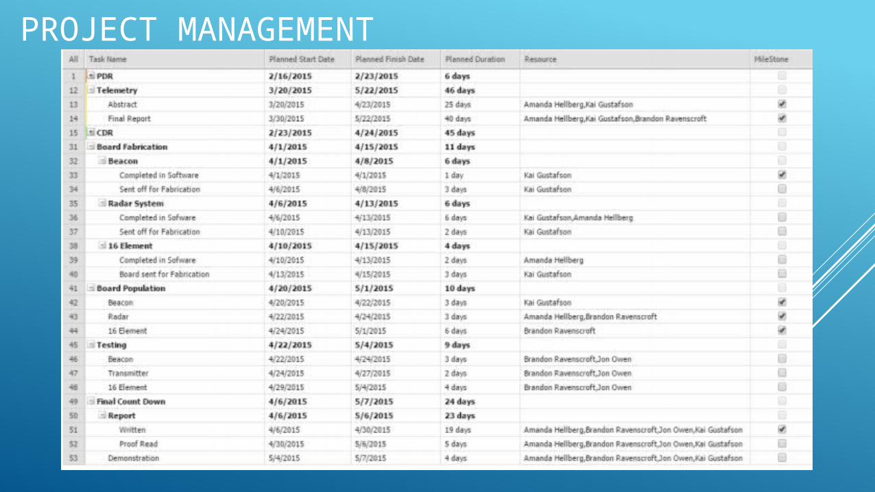
PROJECT MANAGEMENT

GANTT CHART
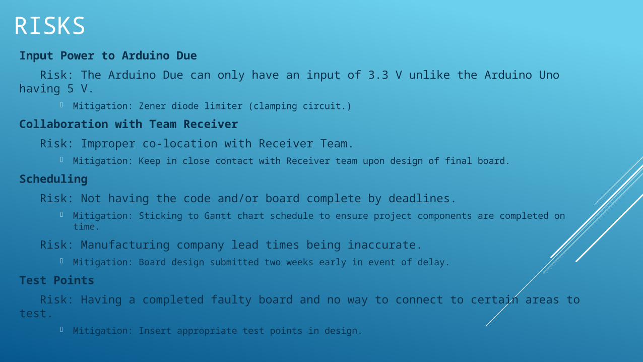
RISKSInput Power to Arduino Due
Risk: The Arduino Due can only have an input of 3.3 V unlike the Arduino Uno having 5 V.
Mitigation: Zener diode limiter (clamping circuit.)
Collaboration with Team Receiver
Risk: Improper co-location with Receiver Team. Mitigation: Keep in close contact with Receiver team upon design of final board.
Scheduling
Risk: Not having the code and/or board complete by deadlines. Mitigation: Sticking to Gantt chart schedule to ensure project components are completed on time.
Risk: Manufacturing company lead times being inaccurate. Mitigation: Board design submitted two weeks early in event of delay.
Test Points
Risk: Having a completed faulty board and no way to connect to certain areas to test.
Mitigation: Insert appropriate test points in design.

QUESTIONS?