Embed Size (px)
Citation preview
1
Ultrasonic Evaluation of Artificial Kissing Bonds in CFRP Composites
Michael WOOD1, Peter CHARLTON
1, Dawei YAN
2
1 NDT Laboratory, University of Wales Trinity Saint David; Swansea, Wales
Phone: +44 1792 481000, e-mail: [email protected] 2 TWI Technology Centre Wales; Port Talbot, Wales; E-mail: [email protected]
Abstract
The primary aim of this paper is to create artificial inter-laminar kissing bond-like defects in CFRP panels for
ultrasonic inspection. Carbon fibre reinforced polymer structures pose a unique problem, as unlike metal-to-
metal bonds (single bond line) carbon fibre reinforced polymer composites have multiple bond lines (between
each laminate layer and between the individual carbon fibre bundles). This increases the number of locations for
kissing bonds and other defects to lie. Published works look at bonding defects in joints (lap joints, and solid-
solid bonding). This paper looks at inter-laminar bonding. A number of samples are created and attempts are
then made to detect these kissing bonds using ultrasonic techniques. Further investigation into contaminants for
artificial defect creation is advised and destructive verification of the kissing bond samples is still required.
Keywords: NDT, Kissing Bond, CFRP, Carbon Fibre Composite, Ultrasound Inspection
1. Introduction
The primary aim of this paper is to create artificial inter-laminar kissing bond-like defects in
CFRP panels. Literature is researched to investigate methods used to artificially create kissing
bond type defects in other material bonds. These methods are then applied to manufacture
CFRP kissing bond samples. The samples are then tested in an immersion tank using the pulse
echo method.
A kissing bond is a bond line defect where two surfaces are in intimate contact, but are not
glued, or have greatly reduced bond strength. A number of bond line defects exist, including
cracks, voids, delaminations, and porosity. These defects are all detectable using current non-
destructive test methods. However, no method is currently available for detecting kissing
bonds in CFRP composites. The danger with kissing bonds is that from the outside they
appear to be solidly bonded, but the bond strength between the two adherends is of very low
or no strength. These weakened bonds can deteriorate due to in-service loading or
environmental conditions, leading to catastrophic failure. This research contributes the
following to the collective scientific knowledge base:
1) Creation of kissing bonds in CFRP composites for ultrasonic inspection
The creation of kissing bonds or kissing bond-like defects is a very difficult process, and an
artificial defect for one inspection method may not be suitable for another method. For
example PTFE inserts are used to simulate delamination in composites for ultrasound
inspection. However, a shearography camera would see the surface deflection caused by the
insert even before a vacuum load was applied. Similarly, methods used to create artificial
kissing bond defects in other bonds may not be suitable for CFRP, due to the type of adhesive
or the material itself.
2) C-Scan evaluation of inserted contamination
A clean, defect free CFRP sample is ultrasonically C-Scanned in an immersion tank to record
baseline readings. The series of manufactured defect samples is then ultrasonically C-Scanned
in the immersion tank. The time of flight data is then analysed. Any detection of a defect will
www.ndt.net/?id=16911Vol.19 No.12 (Dec 2014) - The e-Journal of Nondestructive Testing - ISSN 1435-4934
2
mean that the attempted creation of a kissing bond has failed. Although no indication of a
defect does not necessarily confirm the production of a kissing bond.
2. Problem Definition
2.1 Kissing Bond Definition Kissing bonds are most often found in adhesively bonded structures, but they have also been
found in metal-to-metal structures such as friction stir welds. There are many different
definitions of a kissing bond, with similar properties, but no unified definition, as the
mechanics of a kissing bond cannot be agreed upon. There appears to be some disagreement
as to where poor adhesive bonding becomes a kissing bond. Some believe that only zero
strength bonds where the surfaces are contacting can be classed as kissing bonds, whereas
others believe that bonds which fail at less than 20% of their nominal strength are kissing
bonds. “This form of poor adhesion can be thought of as lying somewhere between the poor
adhesion case and the wholly disbonded case”[1].
In [2], Nagy describes a kissing bond as a bond having "intimate mechanical contact between
the counterparts without an actual bond. Besides some weak sticking effects, such a 'bond' has
practically no strength at all". Whereas in [3] a kissing bond is described as a disbond with the
two surfaces still in contact, which fails under very low stress compared to nominal stress,
and are “identical to perfect joints in all respects but with low adhesion strength”. A further
description is given by Roach et al [4] where a kissing bond is described as a bond where
there is intimate contact between the adherend and the adhesive, but reduced bond strength.
The paper goes on to state that kissing bonds are created due to inadequate surface
preparation, contamination, adhesive degradation, or environmental aging, such as corrosion
and moisture intrusion. In simple terms, a kissing bond is like two slices of frozen bread stuck
together. The surfaces are touching and the structure appears to be stuck together, but it has
little or no bond strength. Once the slices are separated it is seen that there is not 100%
coverage of ice which bonds the two together.
2.2 Defect Sample Creation In order to test for defects, samples with defects must first be created. This in itself creates a
difficulty, for the defect is within the sample, thus not visible on the outside. There is also no
reliable method for finding kissing bonds, so it is not possible to discover whether or not a
kissing bond has been successfully created without destructively testing the samples. In [3], to
be classified as a kissing bond defect the samples had to meet three criteria 1) the bond
strength must be 20% or less of the nominal strength 2) the failure must be purely interfacial
and 3) they must not be detectable with ultrasonic C-Scans. Published works look at bonding
defects in joints (lap joints, and solid-solid bonding). This paper looks at inter-laminar
bonding.
In [2], Nagy used selected spots of release agent to create artificial kissing bonds in
aluminium-epoxy bonded plates. Marty et al [3] states that kissing bond “formation is linked
to one or a combination of problems at the surface such as the introduction of contaminants,
e.g. fuel and hydraulic or de-icer fluids”. However, it was noted that only silicone based
contaminants weaken the bond strength. Silicone contamination and electro release epoxy
were used to create kissing bonds in aluminium-to-aluminium epoxy bonds. Whilst electro
release epoxy was used, the authors noted that despite careful control of the applied voltage
and the duration of the applied voltage, it was difficult to determine the percentage of bond
strength lost from sample to sample. In [5], Yan also used electro-release epoxy and
lubricating oil to simulate kissing bonds in bonded aluminium samples and along with
3
Amerini et al [6] used two compressively loaded specimens to create varying levels of contact
force between the two surfaces to simulate imperfectly contacting surfaces (kissing bond
simulation). As the applied force is reduced, the interface between the two surfaces weakens
and is allowed to vibrate, creating a ‘clapping’ motion between the surfaces.
Roach et al [4] created reduced strength bonds (such as kissing bonds) using a variety of
different contaminants. These included grease, water, wax, sand, vaseline, oil, baking powder,
and mould release agents (pure and diluted). Silicon-based release agent was also used by [7]
to form kissing bonds. Contaminants were uniformly applied across the bond area, with the
distribution controlled by applying the contaminant through screens to ensure specific surface
area coverage. Kissing bonds were also created using less than 100% adhesive coverage.
However, as pre-preg carbon fibre is to be used this option will not be possible. [8] Created
kissing bonds by adding 25-50mm diameter flat bottom holes into the rear of a carbon fibre
covered aluminium honeycomb panel. This would indeed show areas of weak bonding using
Shearography. However, UT would pick this up as a near surface back wall similar to a
delamination, so this method is not appropriate for ultrasonic application. [9] Created kissing
bonds using ETFE [ethylenetetrafluor-oethylene] based, fluoro-polymer release film. Release
film may allow sound reflection for ultrasonic testing. However, this will depend on the
thickness of the film, and the test frequency used.
3 Experimental Work
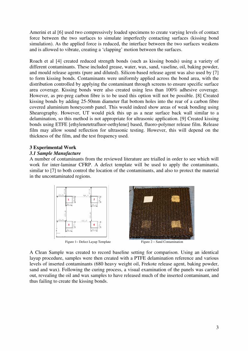
3.1 Sample Manufacture A number of contaminants from the reviewed literature are trialled in order to see which will
work for inter-laminar CFRP. A defect template will be used to apply the contaminants,
similar to [7] to both control the location of the contaminants, and also to protect the material
in the uncontaminated regions.
Figure 1~ Defect Layup Template Figure 2 ~ Sand Contamination
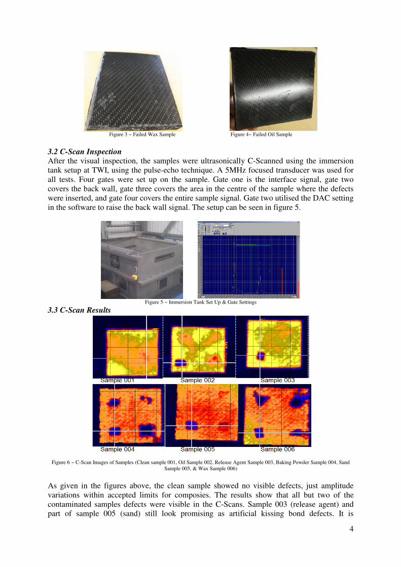
A Clean Sample was created to record baseline setting for comparison. Using an identical
layup procedure, samples were then created with a PTFE delamination reference and various
levels of inserted contaminants (680 heavy weight oil, Frekote release agent, baking powder,
sand and wax). Following the curing process, a visual examination of the panels was carried
out, revealing the oil and wax samples to have released much of the inserted contaminant, and
thus failing to create the kissing bonds.
4
Figure 3 ~ Failed Wax Sample Figure 4~ Failed Oil Sample
3.2 C-Scan Inspection After the visual inspection, the samples were ultrasonically C-Scanned using the immersion
tank setup at TWI, using the pulse-echo technique. A 5MHz focused transducer was used for
all tests. Four gates were set up on the sample. Gate one is the interface signal, gate two
covers the back wall, gate three covers the area in the centre of the sample where the defects
were inserted, and gate four covers the entire sample signal. Gate two utilised the DAC setting
in the software to raise the back wall signal. The setup can be seen in figure 5.
Figure 5 ~ Immersion Tank Set Up & Gate Settings
3.3 C-Scan Results
Figure 6 ~ C-Scan Images of Samples (Clean sample 001, Oil Sample 002, Release Agent Sample 003, Baking Powder Sample 004, Sand
Sample 005, & Wax Sample 006)
As given in the figures above, the clean sample showed no visible defects, just amplitude
variations within accepted limits for composies. The results show that all but two of the
contaminated samples defects were visible in the C-Scans. Sample 003 (release agent) and
part of sample 005 (sand) still look promising as artificial kissing bond defects. It is
5
interesting to note that the smaller amounts of sand contamination were visible in the c-scans,
though the largest level of contaminant was not.
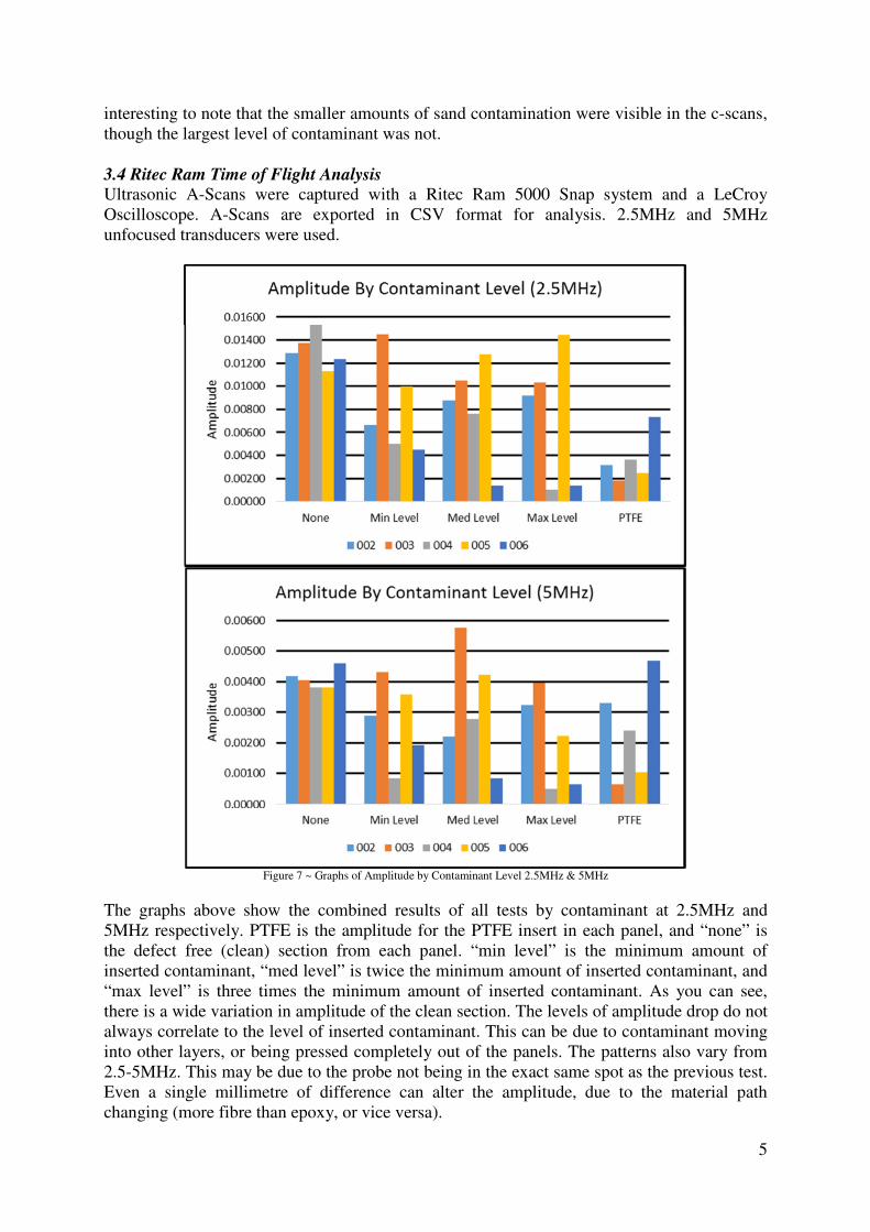
3.4 Ritec Ram Time of Flight Analysis Ultrasonic A-Scans were captured with a Ritec Ram 5000 Snap system and a LeCroy
Oscilloscope. A-Scans are exported in CSV format for analysis. 2.5MHz and 5MHz
unfocused transducers were used.
Figure 7 ~ Graphs of Amplitude by Contaminant Level 2.5MHz & 5MHz
The graphs above show the combined results of all tests by contaminant at 2.5MHz and
5MHz respectively. PTFE is the amplitude for the PTFE insert in each panel, and “none” is
the defect free (clean) section from each panel. “min level” is the minimum amount of
inserted contaminant, “med level” is twice the minimum amount of inserted contaminant, and
“max level” is three times the minimum amount of inserted contaminant. As you can see,
there is a wide variation in amplitude of the clean section. The levels of amplitude drop do not
always correlate to the level of inserted contaminant. This can be due to contaminant moving
into other layers, or being pressed completely out of the panels. The patterns also vary from
2.5-5MHz. This may be due to the probe not being in the exact same spot as the previous test.
Even a single millimetre of difference can alter the amplitude, due to the material path
changing (more fibre than epoxy, or vice versa).
6
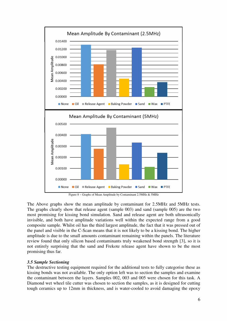
Figure 8 ~ Graphs of Mean Amplitude by Contaminant 2.5MHz & 5MHz
The Above graphs show the mean amplitude by contaminant for 2.5MHz and 5MHz tests.
The graphs clearly show that release agent (sample 003) and sand (sample 005) are the two
most promising for kissing bond simulation. Sand and release agent are both ultrasonically
invisible, and both have amplitude variations well within the expected range from a good
composite sample. Whilst oil has the third largest amplitude, the fact that it was pressed out of
the panel and visible in the C-Scan means that it is not likely to be a kissing bond. The higher
amplitude is due to the small amounts contaminant remaining within the panels. The literature
review found that only silicon based contaminants truly weakened bond strength [3], so it is
not entirely surprising that the sand and Frekote release agent have shown to be the most
promising thus far.
3.5 Sample Sectioning The destructive testing equipment required for the additional tests to fully categorise these as
kissing bonds was not available. The only option left was to section the samples and examine
the contaminant between the layers. Samples 002, 003 and 005 were chosen for this task. A
Diamond wet wheel tile cutter was chosen to section the samples, as it is designed for cutting
tough ceramics up to 12mm in thickness, and is water-cooled to avoid damaging the epoxy
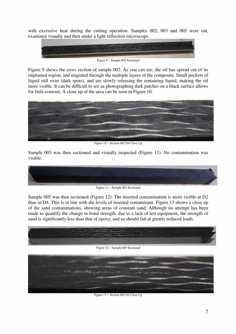
7
with excessive heat during the cutting operation. Samples 002, 003 and 005 were cut,
examined visually and then under a light reflection microscope.
Figure 9 ~ Sample 002 Sectioned
Figure 9 shows the cross section of sample 002. As you can see, the oil has spread out of its
implanted region, and migrated through the multiple layers of the composite. Small pockets of
liquid still exist (dark spots), and are slowly releasing the remaining liquid, making the oil
more visible. It can be difficult to see as photographing dark patches on a black surface allows
for little contrast. A close up of the area can be seen in Figure 10.
Figure 10 ~ Section 002 D4 Close Up
Sample 003 was then sectioned and visually inspected (Figure 11). No contamination was
visible.
Figure 11 ~ Sample 003 Sectioned
Sample 005 was then sectioned (Figure 12). The inserted contamination is more visible at D2
than in D4. This is in line with the levels of inserted contaminant. Figure 13 shows a close up
of the sand contaminations, showing areas of constant sand. Although no attempt has been
made to quantify the change in bond strength, due to a lack of test equipment, the strength of
sand is significantly less than that of epoxy, and so should fail at greatly reduced loads.
Figure 12 ~ Sample 005 Sectioned
Figure 13 ~ Section 005 D2 Close Up
8
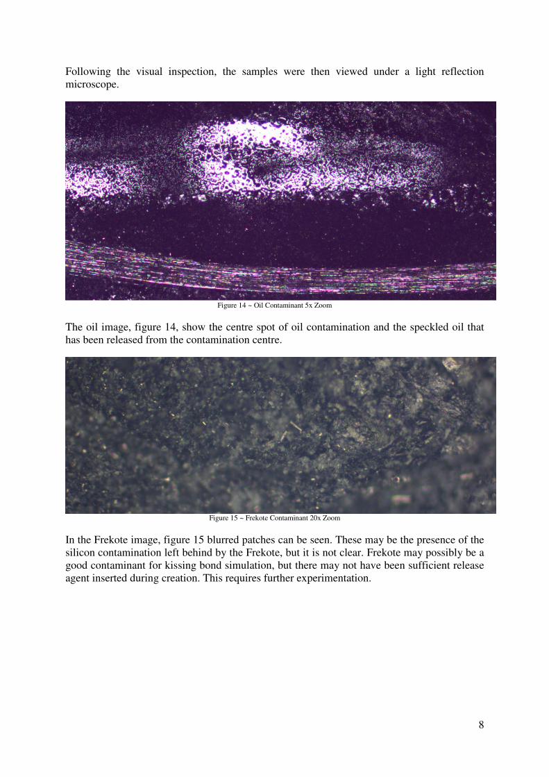
Following the visual inspection, the samples were then viewed under a light reflection
microscope.
Figure 14 ~ Oil Contaminant 5x Zoom
The oil image, figure 14, show the centre spot of oil contamination and the speckled oil that
has been released from the contamination centre.
Figure 15 ~ Frekote Contaminant 20x Zoom
In the Frekote image, figure 15 blurred patches can be seen. These may be the presence of the
silicon contamination left behind by the Frekote, but it is not clear. Frekote may possibly be a
good contaminant for kissing bond simulation, but there may not have been sufficient release
agent inserted during creation. This requires further experimentation.
9
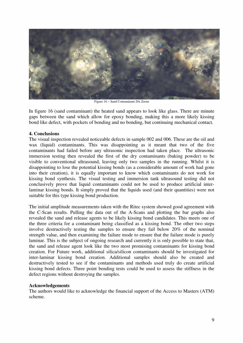
Figure 16 ~ Sand Contaminant 20x Zoom
In figure 16 (sand contaminant) the heated sand appears to look like glass. There are minute
gaps between the sand which allow for epoxy bonding, making this a more likely kissing
bond like defect, with pockets of bonding and no bonding, but continuing mechanical contact.
4. Conclusions
The visual inspection revealed noticeable defects in sample 002 and 006. These are the oil and
wax (liquid) contaminants. This was disappointing as it meant that two of the five
contaminants had failed before any ultrasonic inspection had taken place. The ultrasonic
immersion testing then revealed the first of the dry contaminants (baking powder) to be
visible to conventional ultrasound, leaving only two samples in the running. Whilst it is
disappointing to lose the potential kissing bonds (as a considerable amount of work had gone
into their creation), it is equally important to know which contaminants do not work for
kissing bond synthesis. The visual testing and immersion tank ultrasound testing did not
conclusively prove that liquid contaminants could not be used to produce artificial inter-
laminar kissing bonds. It simply proved that the liquids used (and their quantities) were not
suitable for this type kissing bond production.
The initial amplitude measurements taken with the Ritec system showed good agreement with
the C-Scan results. Pulling the data out of the A-Scans and plotting the bar graphs also
revealed the sand and release agents to be likely kissing bond candidates. This meets one of
the three criteria for a contaminant being classified as a kissing bond. The other two steps
involve destructively testing the samples to ensure they fail below 20% of the nominal
strength value, and then examining the failure mode to ensure that the failure mode is purely
laminar. This is the subject of ongoing research and currently it is only possible to state that,
the sand and release agent look like the two most promising contaminants for kissing bond
creation. For Future work, additional silica/silicon contaminants should be investigated for
inter-laminar kissing bond creation. Additional samples should also be created and
destructively tested to see if the contaminants and methods used truly do create artificial
kissing bond defects. Three point bending tests could be used to assess the stiffness in the
defect regions without destroying the samples.
Acknowledgements The authors would like to acknowledge the financial support of the Access to Masters (ATM)
scheme.
10
References
[1] Brotherhood, C. J., Drinkwater, B. A. & Dixon, S., 2003. The detectability of kissing
bonds in adhesive joints using ultrasonic techniques. Ultrasonics, pp. 521-529.
[2] Nagy, P. B., 1991. Ultrasonic detection of kissing bonds at adhesive interfaces. Journal of
adhesion science, 5(8), pp. 619-630.
[3] Marty, P. N., Desaï, N. & Andersson, J., 2004. NDT of kissing bond in Aeronautical
structures. 16th WCNDT, Roma, CSM Materialteknik AB, Linköping, Sweden.
[4] Roach, D., Rackow, K. & Duvall, R., 2010. Innovative Use of Adhesive Interface
Characteristics to Non-destructively Quantify the Strength of Bonded Joints. The e-
Journal of Non-destructive Testing - ISSN 1435-4934, Vol.15 (No.08).
[5] Yan, D., 2010. The detectability of kissing bonds in adhesive joints using non-linear
ultrasonic techniques, Bristol: Faculty of Engineering, Department of Mechanical
Engineering, University of Bristol.
[6] Amerini, F., Barbieri, E., Meo, M. & Polimeno, U., 2009. Non-Linear Vibration Method
to Detect Imperfectly Contact Interfaces in Composite Beams. Edinburgh, 17th
International Conference on Composite Materials.
[7] Ecault, R. et al., 2012. Laser Adhesion Test for Adhesive Bonded CFRP Structures. 4th
International Symposium on NDT in Aerospace 2012.
[8] Guo, G., Tu, J., Zhang, Y. & Shi, Y., 2012. Inspection of Kissing-bond Defect in
Honeycomb Structure by shearography. Durban, South Africa, 18th World Conference
on Non destructive Testing.
[9] Vijaya Kumar, R. L., Bhat, M. R. & Murthy, C. R., 2013. Evaluation of kissing bond in
composite adhesive lap joints using digital image correlation: Preliminary studies.
International Journal of Adhesion & Adhesives, Issue 42, pp. 60-68.


![CFRP [Wet-preg]](https://img.pdfslide.us/doc/110x75/546e6828b4af9faa268b4674/cfrp-wet-preg.jpg)