Embed Size (px)
Citation preview
PRINTED AND MADE IN THE USA
Important Notice:In order to obtain warranty service on your UltraProteus unit, the serial number sticker must be intact and you musthave a sales receipt or other proof of purchase. If there is no serial number sticker on UltraProteus, please contactE-mu Systems at once.
Manual - Riley Smith
E-mu World HeadquartersE-mu Systems, Inc. U.S.A.P.O. Box 660015Scotts Valley, CA USA95067–0015Telephone: 408-438-1921Fax: 408-438-8612
UltraProteusOperation Manual© 1994 E-mu Systems, Inc.All Rights Reserved
FI434 Rev. A
This product is covered under one or more of the following U. S. patents: 3,969,682; 3,986,423; 4,404,529;4,506,579; 4,699,038; 4,987,600; 5,013,105; 5,072,645; 5,111,727 and foreign patents and/or pendingpatents. UltraProteus is a registered trademark of E-mu Systems, Inc.
Europe, Africa, Middle EastE-mu Systems, Ltd.Suite 6, Adam Ferguson HouseEskmills Industrial ParkMusselburgh, East LothianScotland, EH21 7PQTelephone: 44-31-653-6556Fax: 44-31-665-0473
WARNING: READ THIS FIRST!
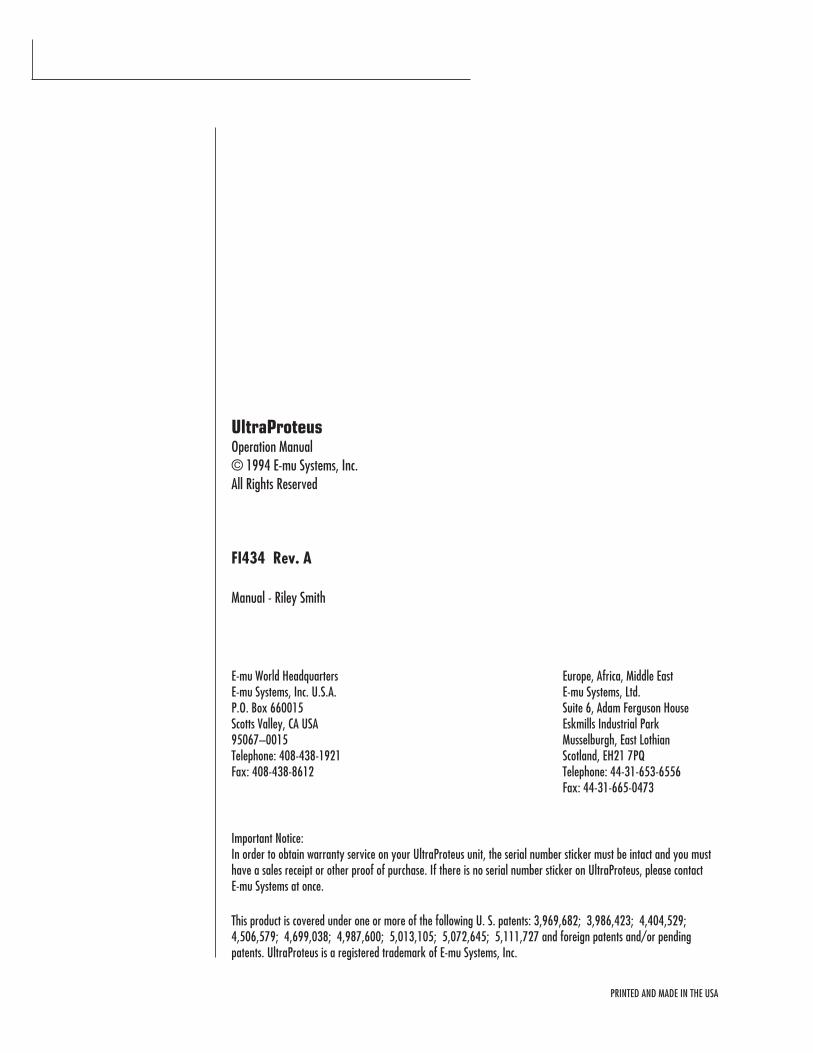
This symbol is intended to alertthe user to the presence ofimportant operating andmaintenance (servicing)instructions in the literatureaccompanying the appliance.
This symbol is intended to alertthe user to the presence ofuninsulated dangerous voltagewithin the product's enclosurethat may be of sufficientmagnitude to constitute a risk ofelectric shock to persons.
i
In this document, whenever theword “UltraProteus” ismentioned, we are referring tothe UltraProteus Synthesizer byE-mu Systems, Inc.
IMPORTANT SAFETY INSTRUCTIONSUse in countries other than the U.S.A. may require the use of a different line
cord or attachment plug, or both. To reduce the risk of fire or electric shock,
refer servicing to qualified service personnel. To reduce risk of fire or electric
shock do not expose this product to rain or moisture.
GROUNDING INSTRUCTIONSThis product must be grounded. If it should malfunction or break down,
grounding provides a path of least resistance for electric current, reducing the
risk of electric shock. This product is equipped with a cord having an equip-
ment-grounding conductor and a grounding plug. The plug must be plugged
into an appropriate outlet properly installed and grounded in accordance with
all local codes and ordinances.
DANGERImproper connection of equipment grounding conductor can result in the risk
of electric shock. Check with a qualified electrician or service personnel if you
are in doubt as to whether the product is properly grounded. Do not modify the
plug provided with this product — if it will not fit the outlet, have a proper
outlet installed by a qualified technician.
CAUTIONIf the UltraProteus (model number 9053), is rack mounted, a standard 19-inch
open frame rack must be used.
USER-MAINTENANCE INSTRUCTIONS1. UltraProteus should be kept clean and dust free. Periodically wipe the unit
with a clean, lint free cloth. Do not use solvents or cleaners.
2. There are no user lubrication or adjustment requirements.
3. Refer all other servicing to qualified service personnel.
INSTRUCTIONS PERTAINING TO A RISK OF FIRE, ELECTRIC SHOCK, ORINJURY TO PERSONS
WARNING; When using electric products, basic precautionsshould always be followed, including the following:
1. Read all instructions before using UltraProteus.
2. To reduce the risk of injury, close supervision is necessary when UltraProteus
is used near children.
3. Do not use UltraProteus near water — for example near a bathtub, washbowl,
kitchen sink, in a wet basement, on a wet bar, or near or in a swimming pool.
4. UltraProteus should be situated so that its location or position does not
interfere with its proper ventilation.
SAVE THESE INSTRUCTIONS
5. UltraProteus should be located away from heat sources such as radiators, heat
registers, fireplaces, stoves, or ovens.
6. UltraProteus should only be connected to a power supply of the type de-
scribed in the operating instructions and as marked on the product.
7. This product, in combination with an amplifier, headphones, and speakers,
may be capable of producing sound levels that could cause full or partial
hearing loss or damaged equipment. Do not operate for long periods of time
at high volume levels or at a level that is uncomfortable. Additionally, care
must be taken when programming any of the filters contained herein using
extreme operating parameters. This action could also produce signals which
result in unacceptable high sound levels as noted previously. If you experi-
ence any hearing loss or ringing of the ears consult your physician.
8. UltraProteus may be equipped with a polarized line plug (one blade wider that
the other). This is a safety feature. If you are unable to insert this plug into
the outlet, do not defeat the safety purpose of the plug. Contact an electrician
to replace your obsolete outlet.
9. The power supply cord of UltraProteus should be unplugged from the outlet
when left unused for a long period of time.
10. Care should be taken so that objects do not fall and liquids are not spilled
into the enclosure of UltraProteus through openings.
11. The product should be serviced by qualified service personnel when:
A. The power supply cord has been damaged; or
B. Objects have fallen on, or liquid has been spilled into the product; or
C. The product has been exposed to rain; or
D. The product does not appear to operate normally or exhibits a marked change in performance; or
E. The product has been dropped or the enclosure damaged.
12. All servicing should be referred to qualified service personnel.
SAVE THESE INSTRUCTIONS
ii
TABLE OF CONTENTS
iii
INTRODUCTION & BASIC SETUP 1
Introduction .................................................................................................................... 3Getting Started ................................................................................................................ 4Connection Instructions .................................................................................................... 5Background - About Sampling .......................................................................................... 9
BASIC OPERATION 11
Main Controls ................................................................................................................ 12Selecting MIDI Channels ................................................................................................. 14Selecting Presets/Hyperpresets ...................................................................................... 14Adjusting Volume & Pan Position .................................................................................... 14Memory Card ................................................................................................................ 15Midimap Selection ......................................................................................................... 15Multi-Timbral Operation ................................................................................................. 16Playing the Demo Sequences ......................................................................................... 16Master Menu ................................................................................................................. 17Enabling the Master Menu ............................................................................................. 19Master Tune .................................................................................................................. 19Transpose ...................................................................................................................... 19User Key Tuning ............................................................................................................ 20Global Bend .................................................................................................................. 20Global Velocity Curve ..................................................................................................... 20MIDI Mode .................................................................................................................... 22MIDI Mode Change ........................................................................................................ 22MIDI Program Change Map ............................................................................................ 23MIDI Controller Assign ................................................................................................... 24MIDI Footswitch Control ................................................................................................. 24Send MIDI Data ............................................................................................................. 24Sysex Packet Delay ....................................................................................................... 25Proteus Sysex ................................................................................................................ 26Auto Select .................................................................................................................... 26Compare Mode .............................................................................................................. 26Viewing Angle ............................................................................................................... 26Midimap Menu .............................................................................................................. 27The Midimap ................................................................................................................. 29Enabling the Midimap Menu ........................................................................................... 30Midimap Select .............................................................................................................. 30Midimap Name.............................................................................................................. 31Program to Channel Assign ............................................................................................ 31Volume, Pan & Output Mix ............................................................................................ 31
TABLE OF CONTENTS
iv
MIDIMAP MENU (cont)
MIDI Enables ................................................................................................................. 33Bank Select ................................................................................................................... 33Program Map Select ...................................................................................................... 34FX A .............................................................................................................................. 34FX B .............................................................................................................................. 35FX Amount .................................................................................................................... 35FX Output Select ............................................................................................................ 36Save Midimap ............................................................................................................... 36
EFFECTS SECTION 37
Where are the Effects? ................................................................................................... 39Effects Output Routing ................................................................................................... 40UltraProteus Effects Bus Architecture .............................................................................. 40Effect Programming Instructions ..................................................................................... 41Reverb .......................................................................................................................... 42Stereo Flanger ............................................................................................................... 46Stereo Phaser ................................................................................................................ 48Stereo Chorus ................................................................................................................ 49Stereo Delay ................................................................................................................. 50Stereo Cross Delay ......................................................................................................... 51Stereo Echo ................................................................................................................... 52“B” Effects .................................................................................................................... 53Stereo Fuzz ................................................................................................................... 54Ring Modulator ............................................................................................................. 55
HYPERPRESET MENU 57
The Hyperpreset ............................................................................................................ 59Enabling the Hyperpreset Menu ..................................................................................... 59Hyperpreset Name ........................................................................................................ 60Preset to Zone Assignment ............................................................................................. 60Zone Volume and Pan .................................................................................................... 61Zone Key Range ............................................................................................................ 61Zone Velocity Range ...................................................................................................... 62Zone Velocity Offset ...................................................................................................... 63Zone Transpose ............................................................................................................. 63Zone Pitch Tune ............................................................................................................. 63Hyperpreset Portamento Mode ....................................................................................... 64Free-Run Function Generator ......................................................................................... 64Save Hyperpreset .......................................................................................................... 66
PRESET PROGRAMMING 67
Starting to Program ....................................................................................................... 69Modulation .................................................................................................................... 70Modulation Sources ....................................................................................................... 71Footswitch Modulation ................................................................................................... 72Midipatch ...................................................................................................................... 72Envelope Generators ...................................................................................................... 73Low Frequency Oscillators .............................................................................................. 75Function Generators ...................................................................................................... 76Filter Modulation ........................................................................................................... 84Parametric Filters .......................................................................................................... 87The UltraProteus Filter ................................................................................................... 88The Z-Plane Filter .......................................................................................................... 89Another View ................................................................................................................. 92UltraProteus Signal Flow ................................................................................................ 93Note-On Modulation Control ........................................................................................... 94Realtime Modulation Control .......................................................................................... 95Key Number .................................................................................................................. 96Velocity Curves .............................................................................................................. 96MIDI Realtime Controls .................................................................................................. 97
PRESET MENU 99
Enabling the Preset Menu ............................................................................................ 101Preset Name ............................................................................................................... 102Primary Instrument ..................................................................................................... 102Secondary Instrument .................................................................................................. 102Volume ....................................................................................................................... 103Pan ............................................................................................................................. 103Key Range .................................................................................................................. 103Primary Key Range ..................................................................................................... 104Secondary Key Range .................................................................................................. 104Transpose .................................................................................................................... 105Coarse Pitch Tuning ..................................................................................................... 105Fine Pitch Tuning ......................................................................................................... 105Alternate Envelope On/Off .......................................................................................... 105Primary Alternate Envelope Parameters ....................................................................... 106Secondary Alternate Envelope Parameters .................................................................... 106Double + Detune ......................................................................................................... 106Sound Delay ................................................................................................................ 107Sound Start ................................................................................................................. 107
TABLE OF CONTENTS
v
PRESET MENU (cont)
Sound Reverse ............................................................................................................ 107Nontranspose .............................................................................................................. 108Loop Enable ................................................................................................................ 108Loop Offset ................................................................................................................. 108Solo Mode ................................................................................................................... 109Solo Mode Priority ....................................................................................................... 110Portamento Rate ......................................................................................................... 110Portamento Shape ....................................................................................................... 110Portamento Mode ........................................................................................................ 111Crossfade Mode ........................................................................................................... 111Crossfade Direction ...................................................................................................... 112Crossfade Balance and Amount .................................................................................... 112Cross-switch Point ........................................................................................................ 113Primary Filter Type ...................................................................................................... 113Secondary Filter Type .................................................................................................. 113Filter Level .................................................................................................................. 113Morph Offset ............................................................................................................... 114Filter Frequency Tracking ............................................................................................. 114Filter Transform 2 ........................................................................................................ 115Filter Reverse .............................................................................................................. 116Auxiliary Envelope ...................................................................................................... 116LFO 1 & 2 - Shape & Amount ....................................................................................... 117LFO 1 & 2 - Rate, Delay & Variation ............................................................................. 117Function Generator 1 and 2 ......................................................................................... 118Note-On Modulation Control ......................................................................................... 122Realtime Modulation Control ........................................................................................ 123Footswitch Control ....................................................................................................... 124Pitch Bend Range ........................................................................................................ 124Pressure Amount ......................................................................................................... 124MIDI Controller Amount ............................................................................................... 124Velocity Curve ............................................................................................................. 125Keyboard Center ......................................................................................................... 126Keyboard Tuning ......................................................................................................... 126Mix Select ................................................................................................................... 127Save Preset ................................................................................................................. 127
TABLE OF CONTENTS
vi
COPY MENU 129
Enabling the Copy Menu .............................................................................................. 131Copy Preset ................................................................................................................. 131Copy Layer .................................................................................................................. 132Copy Filter .................................................................................................................. 132Copy LFO .................................................................................................................... 132Copy Function Generator ............................................................................................. 133Copy Auxiliary Envelope .............................................................................................. 133Copy Note-On Control .................................................................................................. 133Copy Realtime Control ................................................................................................. 133Copy Hyperpreset ........................................................................................................ 134Copy Zone ................................................................................................................... 134Copy Free-Run Function Generator ............................................................................... 134Copy Midimap ............................................................................................................. 134Copy Channel .............................................................................................................. 135Copy Effects ................................................................................................................ 135Copy Program Change Map .......................................................................................... 135Copy Bank .................................................................................................................. 136
STEP-BY-STEP 137
Forward ...................................................................................................................... 139Editing Presets ............................................................................................................. 139Starting From Scratch .................................................................................................. 140The Instrument ............................................................................................................ 140Volume ....................................................................................................................... 141Pan ............................................................................................................................. 141Transpose .................................................................................................................... 141Coarse Tuning ............................................................................................................. 142Fine Tuning ................................................................................................................. 142Alternate Volume Envelope .......................................................................................... 143Anatomy of an Envelope .............................................................................................. 144Sound Delay ................................................................................................................ 145Sound Start ................................................................................................................. 145Application: Sound Splicing .......................................................................................... 146Time to Save?.............................................................................................................. 147LFO Modulation ........................................................................................................... 147Modulating Modulators ................................................................................................ 150The UltraProteus Filter ................................................................................................. 151Just Do It .................................................................................................................... 152Filter Filosophy ............................................................................................................ 154
TABLE OF CONTENTS
vii
STEP-BY-STEP (cont)
Morphology ................................................................................................................ 157Using UltraProteus with a Sequencer ............................................................................ 158More Advanced Sequencing ......................................................................................... 159
REFERENCE SECTION 161
Factory RAM Presets - Bank 0 ...................................................................................... 162Factory ROM Presets - Bank 1 ...................................................................................... 163Instrument Listing ........................................................................................................ 164B3 Wave Diagrams ...................................................................................................... 171Instrument Locations ................................................................................................... 172Percussion Instrument Locations ................................................................................... 173Z-Plane Filter Descriptions ............................................................................................ 178Loop Offset Sample Locations ....................................................................................... 235Function Generator Curves ........................................................................................... 239Function Generator, LFO & Envelope Specifications ....................................................... 247Technical Specifications ................................................................................................ 248MIDI Implementation Chart .......................................................................................... 249MIDI Specifications ...................................................................................................... 250SysEx Tutorial ............................................................................................................. 277
INDEX 281
WARRANTY 285
TABLE OF CONTENTS
viii
Chapter 1: Basic Setup 1
UltraProteus INTRO/BASIC SETUP

UltraProteus Operation Manual2
Chapter 1: Basic Setup 3
PHONESVOLUME
PRESETMASTER
DEMO
CURSOR< >
HOME/ENTER
DATA POWER
MIDI
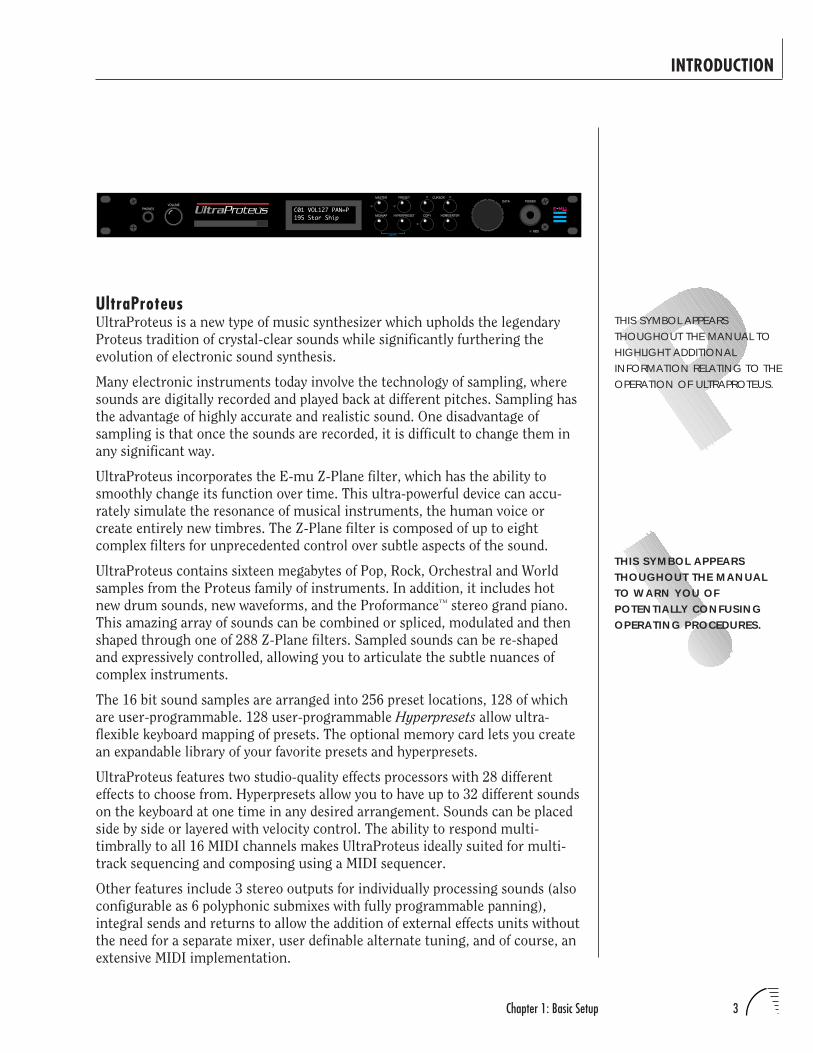
C01 VOL127 PAN=P195 Star Ship HYPERPRESETMIDIMAP COPY
UltraProteus
UltraProteusUltraProteus is a new type of music synthesizer which upholds the legendary
Proteus tradition of crystal-clear sounds while significantly furthering the
evolution of electronic sound synthesis.
Many electronic instruments today involve the technology of sampling, where
sounds are digitally recorded and played back at different pitches. Sampling has
the advantage of highly accurate and realistic sound. One disadvantage of
sampling is that once the sounds are recorded, it is difficult to change them in
any significant way.
UltraProteus incorporates the E-mu Z-Plane filter, which has the ability to
smoothly change its function over time. This ultra-powerful device can accu-
rately simulate the resonance of musical instruments, the human voice or
create entirely new timbres. The Z-Plane filter is composed of up to eight
complex filters for unprecedented control over subtle aspects of the sound.
UltraProteus contains sixteen megabytes of Pop, Rock, Orchestral and World
samples from the Proteus family of instruments. In addition, it includes hot
new drum sounds, new waveforms, and the Proformance™ stereo grand piano.
This amazing array of sounds can be combined or spliced, modulated and then
shaped through one of 288 Z-Plane filters. Sampled sounds can be re-shaped
and expressively controlled, allowing you to articulate the subtle nuances of
complex instruments.
The 16 bit sound samples are arranged into 256 preset locations, 128 of which
are user-programmable. 128 user-programmable Hyperpresets allow ultra-
flexible keyboard mapping of presets. The optional memory card lets you create
an expandable library of your favorite presets and hyperpresets.
UltraProteus features two studio-quality effects processors with 28 different
effects to choose from. Hyperpresets allow you to have up to 32 different sounds
on the keyboard at one time in any desired arrangement. Sounds can be placed
side by side or layered with velocity control. The ability to respond multi-
timbrally to all 16 MIDI channels makes UltraProteus ideally suited for multi-
track sequencing and composing using a MIDI sequencer.
Other features include 3 stereo outputs for individually processing sounds (also
configurable as 6 polyphonic submixes with fully programmable panning),
integral sends and returns to allow the addition of external effects units without
the need for a separate mixer, user definable alternate tuning, and of course, an
extensive MIDI implementation.
INTRODUCTION
THIS SYMBOL APPEARSTHOUGHOUT THE MANUAL TOHIGHLIGHT ADDITIONALINFORMATION RELATING TO THEOPERATION OF ULTRAPROTEUS.
THIS SYMBOL APPEARSTHOUGHOUT THE MANUALTO WARN YOU OFPOTENTIALLY CONFUSINGOPERATING PROCEDURES.
UltraProteus Operation Manual4
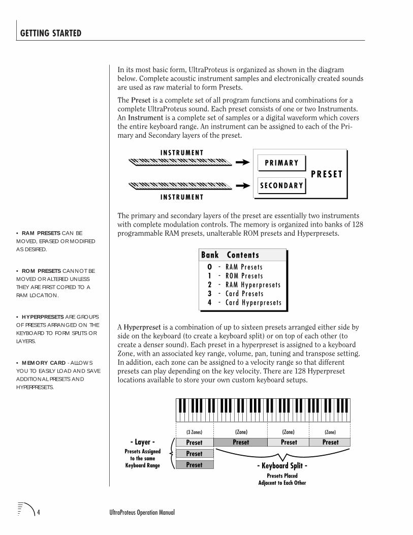
In its most basic form, UltraProteus is organized as shown in the diagram
below. Complete acoustic instrument samples and electronically created sounds
are used as raw material to form Presets.
The Preset is a complete set of all program functions and combinations for a
complete UltraProteus sound. Each preset consists of one or two Instruments.
An Instrument is a complete set of samples or a digital waveform which covers
the entire keyboard range. An instrument can be assigned to each of the Pri-
mary and Secondary layers of the preset.
• RAM PRESETS CAN BEMOVED, ERASED OR MODIFIEDAS DESIRED.
• ROM PRESETS CANNOT BEMOVED OR ALTERED UNLESSTHEY ARE FIRST COPIED TO ARAM LOCATION.
• HYPERPRESETS ARE GROUPSOF PRESETS ARRANGED ON THEKEYBOARD TO FORM SPLITS ORLAYERS.
• MEMORY CARD - ALLOWSYOU TO EASILY LOAD AND SAVEADDITIONAL PRESETS ANDHYPERPRESETS.
The primary and secondary layers of the preset are essentially two instruments
with complete modulation controls. The memory is organized into banks of 128
programmable RAM presets, unalterable ROM presets and Hyperpresets.
I N S T R U M E N T
I N S T R U M E N T
P R E S E TP R I M A R Y
S E C O N D A R Y
Preset Preset
Preset
Preset
Preset Preset- Layer -
- Keyboard Split -
(3 Zones) (Zone) (Zone) (Zone)
Presets PlacedAdjacent to Each Other
Presets Assignedto the same
Keyboard Range
O1234
R A M P r e s e t sR O M P r e s e t sR A M H y p e r p r e s e t sC a r d P r e s e t sC a r d H y p e r p r e s e t s
Bank Contents-----
A Hyperpreset is a combination of up to sixteen presets arranged either side by
side on the keyboard (to create a keyboard split) or on top of each other (to
create a denser sound). Each preset in a hyperpreset is assigned to a keyboard
Zone, with an associated key range, volume, pan, tuning and transpose setting.
In addition, each zone can be assigned to a velocity range so that different
presets can play depending on the key velocity. There are 128 Hyperpreset
locations available to store your own custom keyboard setups.
GETTING STARTED
Chapter 1: Basic Setup 5
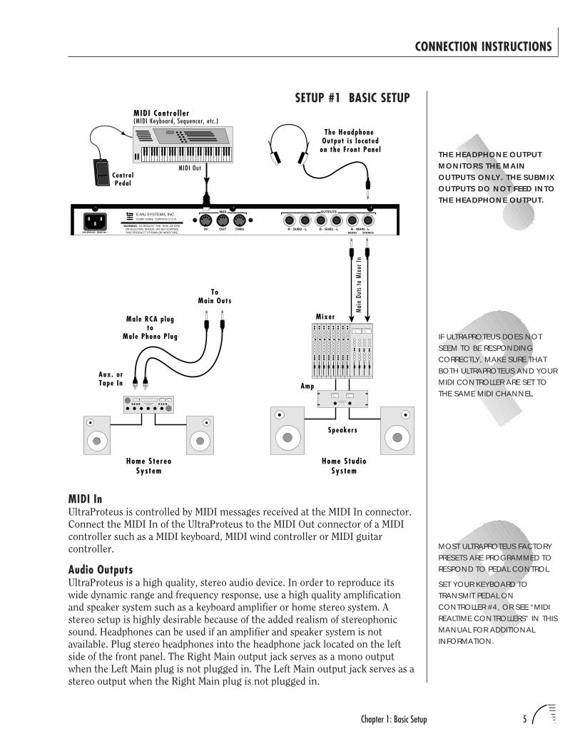
IF ULTRAPROTEUS DOES NOTSEEM TO BE RESPONDINGCORRECTLY, MAKE SURE THATBOTH ULTRAPROTEUS AND YOURMIDI CONTROLLER ARE SET TOTHE SAME MIDI CHANNEL.
THE HEADPHONE OUTPUTMONITORS THE MAINOUTPUTS ONLY. THE SUBMIXOUTPUTS DO NOT FEED INTOTHE HEADPHONE OUTPUT.
CONNECTION INSTRUCTIONS
SETUP #1 BASIC SETUP
MIDI InUltraProteus is controlled by MIDI messages received at the MIDI In connector.
Connect the MIDI In of the UltraProteus to the MIDI Out connector of a MIDI
controller such as a MIDI keyboard, MIDI wind controller or MIDI guitar
controller.
Audio OutputsUltraProteus is a high quality, stereo audio device. In order to reproduce its
wide dynamic range and frequency response, use a high quality amplification
and speaker system such as a keyboard amplifier or home stereo system. A
stereo setup is highly desirable because of the added realism of stereophonic
sound. Headphones can be used if an amplifier and speaker system is not
available. Plug stereo headphones into the headphone jack located on the left
side of the front panel. The Right Main output jack serves as a mono output
when the Left Main plug is not plugged in. The Left Main output jack serves as a
stereo output when the Right Main plug is not plugged in.
R - SUB2 - L R - SUB1 - L R - MAIN - LMONO STEREO
THRUOUTIN
OUTPUTSMIDI
Scotts Valley, California U.S.A.
100-250VAC 50/60 Hz ~
E-MU SYSTEMS, INC.
WARNING: TO REDUCE THE RISK OF FIREOR ELECTRIC SHOCK, DO NOT EXPOSETHIS PRODUCT TO RAIN OR MOISTURE.
Mai
n Ou
ts to
Mix
er In
MIDI Contro l le r(MIDI Keyboard, Sequencer , e tc . )
MIDI Out
Aux. orTape In
Male RCA p lugto
Male Phono P lug
ToMain Outs
Home StereoSystem
Home Stud ioSystem
Speakers
Amp
Mixer
The Headphone Output i s lo cated
on the Front Pane l
Contro lPeda l
MOST ULTRAPROTEUS FACTORYPRESETS ARE PROGRAMMED TORESPOND TO PEDAL CONTROL.
SET YOUR KEYBOARD TOTRANSMIT PEDAL ONCONTROLLER #4, OR SEE “MIDIREALTIME CONTROLLERS” IN THISMANUAL FOR ADDITIONALINFORMATION.
UltraProteus Operation Manual6
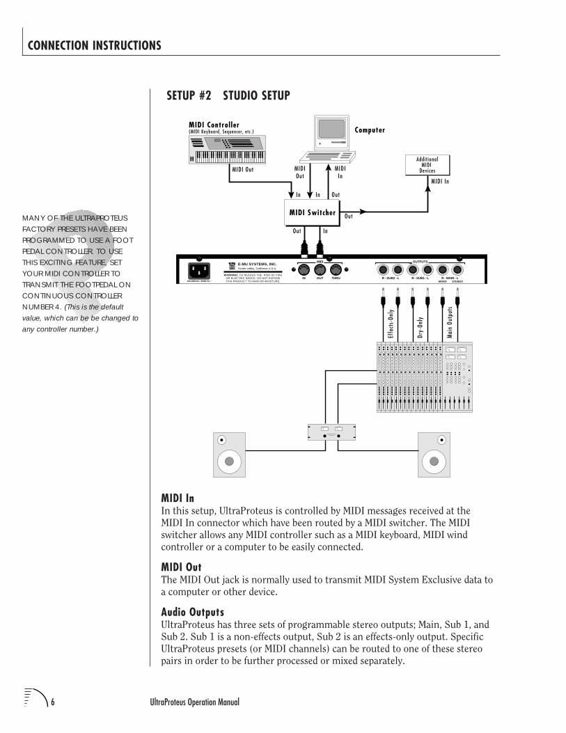
SETUP #2 STUDIO SETUP
CONNECTION INSTRUCTIONS
MANY OF THE ULTRAPROTEUSFACTORY PRESETS HAVE BEENPROGRAMMED TO USE A FOOTPEDAL CONTROLLER. TO USETHIS EXCITING FEATURE, SETYOUR MIDI CONTROLLER TOTRANSMIT THE FOOTPEDAL ONCONTINUOUS CONTROLLERNUMBER 4. (This is the defaultvalue, which can be be changed toany controller number.)
MIDI InIn this setup, UltraProteus is controlled by MIDI messages received at the
MIDI In connector which have been routed by a MIDI switcher. The MIDI
switcher allows any MIDI controller such as a MIDI keyboard, MIDI wind
controller or a computer to be easily connected.
MIDI OutThe MIDI Out jack is normally used to transmit MIDI System Exclusive data to
a computer or other device.
Audio OutputsUltraProteus has three sets of programmable stereo outputs; Main, Sub 1, and
Sub 2. Sub 1 is a non-effects output, Sub 2 is an effects-only output. Specific
UltraProteus presets (or MIDI channels) can be routed to one of these stereo
pairs in order to be further processed or mixed separately.
Effe
cts-
Only
Dry-
Only
Mai
n Ou
tput
s
M IDI Out
MIDI Control ler(MIDI Keyboard, Sequencer , e tc . ) Computer
MIDI In
Addi t ionalMIDI
Devices
MIDI Switcher
MIDIOut
Out In
Out
OutInIn
R - SUB2 - L R - SUB1 - L R - MAIN - LMONO STEREO
THRUOUTIN
OUTPUTSMIDI
Scotts Valley, California U.S.A.
100-250VAC 50/60 Hz ~
E-MU SYSTEMS, INC.
WARNING: TO REDUCE THE RISK OF FIREOR ELECTRIC SHOCK, DO NOT EXPOSETHIS PRODUCT TO RAIN OR MOISTURE.
MIDIIn
Chapter 1: Basic Setup 7
CONNECTION INSTRUCTIONS
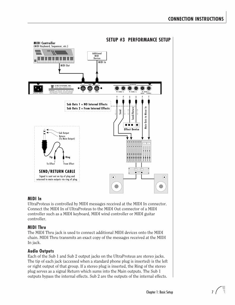
SETUP #3 PERFORMANCE SETUP
R - SUB2 - L R - SUB1 - L R - MAIN - LMONO STEREO
THRUOUTIN
OUTPUTSMIDI
Scotts Valley, California U.S.A.
100-250VAC 50/60 Hz ~
E-MU SYSTEMS, INC.
WARNING: TO REDUCE THE RISK OF FIREOR ELECTRIC SHOCK, DO NOT EXPOSETHIS PRODUCT TO RAIN OR MOISTURE.
Sub OutputReturn(To Main Output)
Tip Ring
To Ef fec t From Effec t
SEND/RETURN CABLE
Send
/Ret
urn
Effect Device
Sub Outs 1 = NO Internal EffectsSub Outs 2 = From Internal Effects
Mai
n Ou
ts to
Mix
er In
Add i t ionalMIDI
Devices
MIDI Control ler(MIDI Keyboard, Sequencer , e tc . )
MIDI OutMIDI In
Send
S ignal i s sent out on t ip of p lug andreturned to main outputs v ia r ing of p lug.
MIDI InUltraProteus is controlled by MIDI messages received at the MIDI In connector.
Connect the MIDI In of UltraProteus to the MIDI Out connector of a MIDI
controller such as a MIDI keyboard, MIDI wind controller or MIDI guitar
controller.
MIDI ThruThe MIDI Thru jack is used to connect additional MIDI devices onto the MIDI
chain. MIDI Thru transmits an exact copy of the messages received at the MIDI
In jack.
Audio OutputsEach of the Sub 1 and Sub 2 output jacks on the UltraProteus are stereo jacks.
The tip of each jack (accessed when a standard phone plug is inserted) is the left
or right output of that group. If a stereo plug is inserted, the Ring of the stereo
plug serves as a signal Return which sums into the Main outputs. The Sub 1
outputs bypass the internal effects. Sub 2 are the outputs of the internal effects.
UltraProteus Operation Manual8
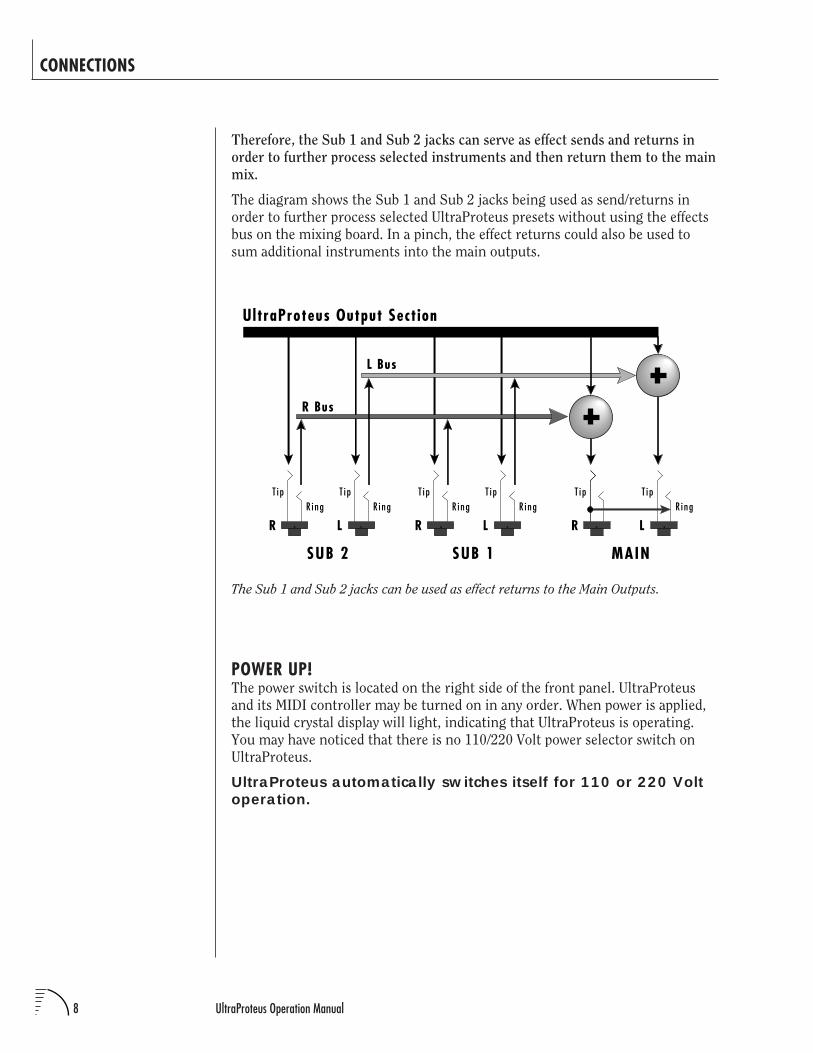
Therefore, the Sub 1 and Sub 2 jacks can serve as effect sends and returns in
order to further process selected instruments and then return them to the main
mix.
The diagram shows the Sub 1 and Sub 2 jacks being used as send/returns in
order to further process selected UltraProteus presets without using the effects
bus on the mixing board. In a pinch, the effect returns could also be used to
sum additional instruments into the main outputs.
The Sub 1 and Sub 2 jacks can be used as effect returns to the Main Outputs.
POWER UP!The power switch is located on the right side of the front panel. UltraProteus
and its MIDI controller may be turned on in any order. When power is applied,
the liquid crystal display will light, indicating that UltraProteus is operating.
You may have noticed that there is no 110/220 Volt power selector switch on
UltraProteus.
UltraProteus automatically switches itself for 110 or 220 Voltoperation.
CONNECTIONS
T i pR i ng
T i pR i ng
T i pR i ng
T i pR i ng
T i p T i pR i ng
SUB 2 SUB 1 MAIN
R L R L R L
R Bus
L Bus
UltraProteus Output Section
Chapter 1: Basic Setup 9
ABOUT SAMPLINGUltraProteus utilizes digital recording of acoustic sounds for the basis of each
Instrument. This is similar to a tape recorder except that inside the
UltraProteus, the sounds are permanently recorded on digital memory chips.
Sound and instrument waveforms are first sampled into the Emulator III, our
top of the line, 16 bit stereo digital sampler. After the sounds and waveforms
have been truncated, looped and processed, they are permanently encoded into
the UltraProteus ROM (Read Only Memory) chips.
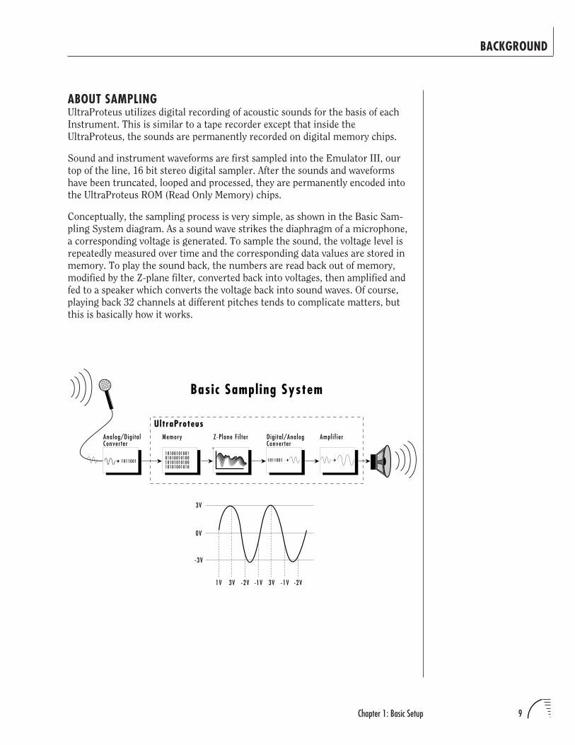
Conceptually, the sampling process is very simple, as shown in the Basic Sam-
pling System diagram. As a sound wave strikes the diaphragm of a microphone,
a corresponding voltage is generated. To sample the sound, the voltage level is
repeatedly measured over time and the corresponding data values are stored in
memory. To play the sound back, the numbers are read back out of memory,
modified by the Z-plane filter, converted back into voltages, then amplified and
fed to a speaker which converts the voltage back into sound waves. Of course,
playing back 32 channels at different pitches tends to complicate matters, but
this is basically how it works.
BACKGROUND
Memory
10100101001010100101001010101010010101001010
Dig i ta l/AnalogConverter
1011001
Z-P lane F i l ter Ampl i f ier
Basic Sampling System
UltraProteusAnalog/Dig i ta lConverter
1011001
-1V -2V3V-1V-2V3V1V
0V
3V
-3V

UltraProteus Operation Manual10

11Chapter 2: Basic Operation
UltraProteus BASIC OPERATION
12 UltraProteus Operation Manual
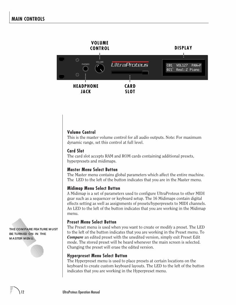
MAIN CONTROLS
Volume ControlThis is the master volume control for all audio outputs. Note: For maximum
dynamic range, set this control at full level.
Card SlotThe card slot accepts RAM and ROM cards containing additional presets,
hyperpresets and midimaps.
Master Menu Select ButtonThe Master menu contains global parameters which affect the entire machine.
The LED to the left of the button indicates that you are in the Master menu.
Midimap Menu Select ButtonA Midimap is a set of parameters used to configure UltraProteus to other MIDI
gear such as a sequencer or keyboard setup. The 16 Midimaps contain digital
effects setting as well as assignments of presets/hyperpresets to MIDI channels.
An LED to the left of the button indicates that you are working in the Midimap
menu.
Preset Menu Select ButtonThe Preset menu is used when you want to create or modify a preset. The LED
to the left of the button indicates that you are working in the Preset menu. To
Compare an edited preset with the unedited version, simply exit Preset Edit
mode. The stored preset will be heard whenever the main screen is selected.
Changing the preset will erase the edited version.
Hyperpreset Menu Select ButtonThe Hyperpreset menu is used to place presets at certain locations on the
keyboard to create custom keyboard layouts. The LED to the left of the button
indicates that you are working in the Hyperpreset menu.
VOLUMECONTROL
HEADPHONEJACK
CARDSLOT
PHONESVOLUME
C01 VOL127 PAN=P021 Real:Z Piano
DISPLAY
1UltraProteus
THE COMPARE FEATURE MUSTBE TURNED ON IN THEMASTER MENU.
13Chapter 2: Basic Operation
THE CURSOR CAN ALSO BEMOVED BIDIRECTIONALLY USINGTHE DATA ENTRY CONTROLWHILE THE RIGHT CURSORBUTTON IS HELD DOWN. (I.E.PRESS AND HOLD THE CURSORBUTTON AND TURN THE DATAENTRY KNOB.)
MAIN CONTROLS
YOU MUST HOLD THEMIDIMAP AND HYPERPRESETBUTTONS FORAPPROXIMATELY TWOSECONDS TO START THEDEMO SEQUENCES.
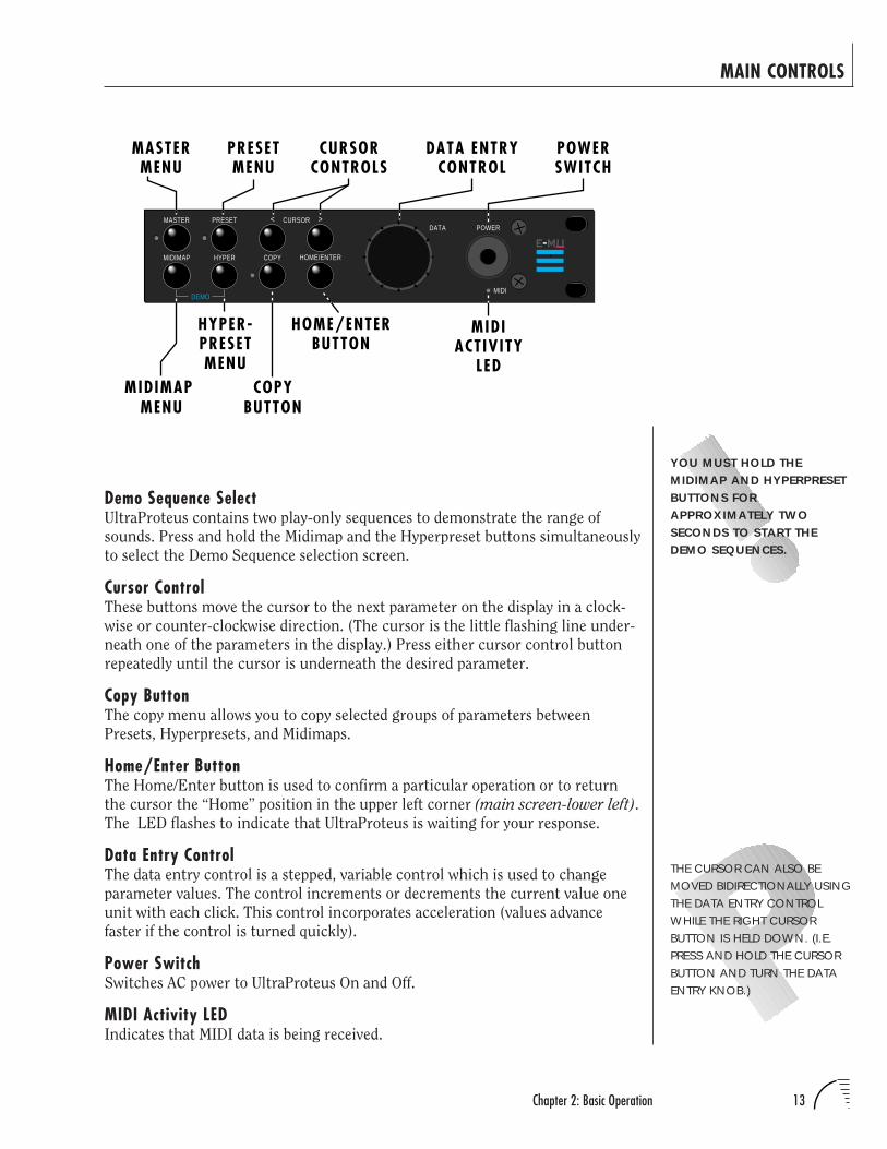
Demo Sequence SelectUltraProteus contains two play-only sequences to demonstrate the range of
sounds. Press and hold the Midimap and the Hyperpreset buttons simultaneously
to select the Demo Sequence selection screen.
Cursor ControlThese buttons move the cursor to the next parameter on the display in a clock-
wise or counter-clockwise direction. (The cursor is the little flashing line under-
neath one of the parameters in the display.) Press either cursor control button
repeatedly until the cursor is underneath the desired parameter.
Copy ButtonThe copy menu allows you to copy selected groups of parameters between
Presets, Hyperpresets, and Midimaps.
Home/Enter ButtonThe Home/Enter button is used to confirm a particular operation or to return
the cursor the “Home” position in the upper left corner (main screen-lower left).
The LED flashes to indicate that UltraProteus is waiting for your response.
Data Entry ControlThe data entry control is a stepped, variable control which is used to change
parameter values. The control increments or decrements the current value one
unit with each click. This control incorporates acceleration (values advance
faster if the control is turned quickly).
Power SwitchSwitches AC power to UltraProteus On and Off.
MIDI Activity LEDIndicates that MIDI data is being received.
COPYBUTTON
PRESETMENU
CURSORCONTROLS
MIDIMAP MENU
MIDIACTIVITY
LED
HOME/ENTERBUTTON
HYPER-PRESETMENU
MASTERMENU
PRESETMASTER
DEMO
CURSOR< >
HOME/ENTER
DATA POWER
MIDI
HYPERMIDIMAP COPY
POWERSWITCH
DATA ENTRYCONTROL
14 UltraProteus Operation Manual
0
BASIC OPERATION
IF ULTRAPROTEUS IS NOTRESPONDING PROPERLY ORPLAYS THE WRONG PRESET,MAKE SURE THAT BOTHULTRAPROTEUS AND YOUR MIDICONTROLLER ARE SET TO THESAME MIDI CHANNEL AND THATTHE MIDI VOLUME IS TURNED UP.
FOR MORE INFORMATIONABOUT MIDI, SEE MIDI REALTIMECONTROLS ON PAGE 97.
O1234
R A M P r e s e t sR O M P r e s e t sR A M H y p e r p r e s e t sC a r d P r e s e t sC a r d H y p e r p r e s e t s
Bank Contents-----
M ID I Channe l
P rog ram No .
Vo l ume
S t e r eo Po s i t i on
P rog ram Name
Bank No .
CHANNEL PAN SHOULDNORMALLY BE SET TO “P”UNLESS REALTIME CONTROL OFPANNING IS DESIRED. IF PAN ISSET TO “0”, STEREO EFFECTSCREATED IN THE PRESET WILL BELOST.
0÷ MIDI Channel Parameters÷ Preset/Hyperpreset Name
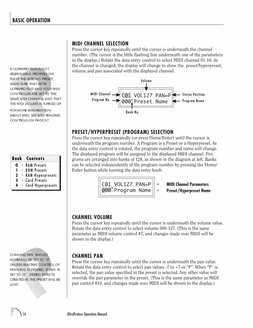
MIDI CHANNEL SELECTIONPress the cursor key repeatedly until the cursor is underneath the channel
number. (The cursor is the little flashing line underneath one of the parameters
in the display.) Rotate the data entry control to select MIDI channel 01-16. As
the channel is changed, the display will change to show the preset/hyperpreset,
volume and pan associated with the displayed channel.
C01 VOL127 PAN=P000 Preset Name
PRESET/HYPERPRESET (PROGRAM) SELECTIONPress the cursor key repeatedly (or press Home/Enter) until the cursor is
underneath the program number. A Program is a Preset or a Hyperpreset. As
the data entry control is rotated, the program number and name will change.
The displayed program will be assigned to the displayed MIDI channel. Pro-
grams are arranged into banks of 128, as shown in the diagram at left. Banks
can be selected independently of the program number by pressing the Home/
Enter button while turning the data entry knob.
C01 VOL127 PAN=P000 Program Name
CHANNEL VOLUMEPress the cursor key repeatedly until the cursor is underneath the volume value.
Rotate the data entry control to select volume 000-127. (This is the same
parameter as MIDI volume control #7, and changes made over MIDI will be
shown in the display.)
CHANNEL PANPress the cursor key repeatedly until the cursor is underneath the pan value.
Rotate the data entry control to select pan values -7 to +7 or “P”. When “P” is
selected, the pan value specified in the preset is selected. Any other value will
override the pan parameter in the preset. (This is the same parameter as MIDI
pan control #10, and changes made over MIDI will be shown in the display.)
15Chapter 2: Basic Operation
BASIC OPERATION
RAM CARDS CAN BE USED TOSTORE YOUR OWN PRESETS,HYPERPRESETS AND MIDIMAPS.
ROM CARDS CONTAINPRE-RECORDED PRESETS,HYPERPRESETS AND MIDIMAPS.YOU CANNOT SAVE DATA TO AROM CARD.
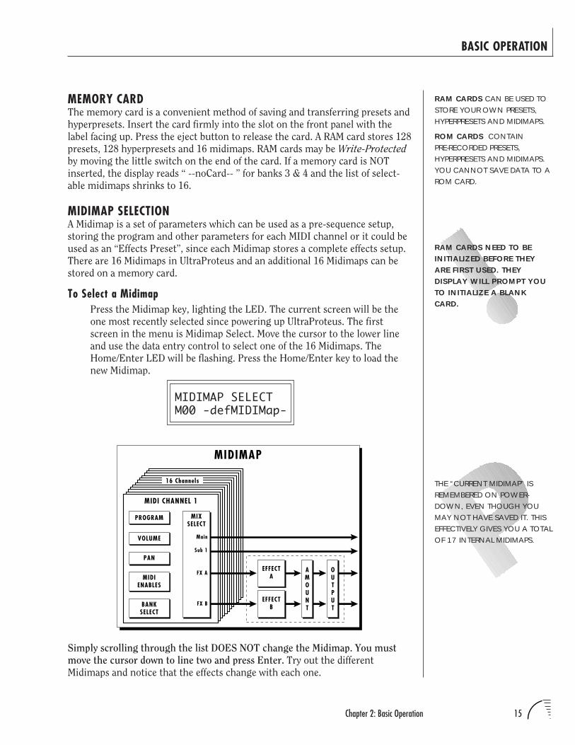
MEMORY CARDThe memory card is a convenient method of saving and transferring presets and
hyperpresets. Insert the card firmly into the slot on the front panel with the
label facing up. Press the eject button to release the card. A RAM card stores 128
presets, 128 hyperpresets and 16 midimaps. RAM cards may be Write-Protected
by moving the little switch on the end of the card. If a memory card is NOT
inserted, the display reads “ --noCard-- ” for banks 3 & 4 and the list of select-
able midimaps shrinks to 16.
MIDIMAP SELECTIONA Midimap is a set of parameters which can be used as a pre-sequence setup,
storing the program and other parameters for each MIDI channel or it could be
used as an “Effects Preset”, since each Midimap stores a complete effects setup.
There are 16 Midimaps in UltraProteus and an additional 16 Midimaps can be
stored on a memory card.
To Select a MidimapPress the Midimap key, lighting the LED. The current screen will be the
one most recently selected since powering up UltraProteus. The first
screen in the menu is Midimap Select. Move the cursor to the lower line
and use the data entry control to select one of the 16 Midimaps. The
Home/Enter LED will be flashing. Press the Home/Enter key to load the
new Midimap.
MIDIMAP SELECTM00 -defMIDIMap-
THE “CURRENT MIDIMAP” ISREMEMBERED ON POWER-DOWN, EVEN THOUGH YOUMAY NOT HAVE SAVED IT. THISEFFECTIVELY GIVES YOU A TOTALOF 17 INTERNAL MIDIMAPS.
Simply scrolling through the list DOES NOT change the Midimap. You must
move the cursor down to line two and press Enter. Try out the different
Midimaps and notice that the effects change with each one.
MIDI CHANNEL 1
MIXSELECT
PROGRAM
FX A
FX B
Main
Sub 1
VOLUME
PAN
MIDIENABLES
BANKSELECT
EFFECTA
AMOUNT
OUTPUT
EFFECTB
16 Channels
MIDIMAP
RAM CARDS NEED TO BEINITIALIZED BEFORE THEYARE FIRST USED. THEYDISPLAY WILL PROMPT YOUTO INITIALIZE A BLANKCARD.
16 UltraProteus Operation Manual
BASIC OPERATION
MULTI-TIMBRAL OPERATIONMulti-timbral operation means that the UltraProteus can play more than one
sound at the same time. To access multiple presets on different MIDI channels
simultaneously, follow these instructions:
1. Set the MIDI mode to MULTI-Mode, using the MIDI mode function in the
Master menu (page 22).
2. Decide which MIDI channels you wish the UltraProteus to receive, and
turn “All Messages” Off for the MIDI channels that you DO NOT want
UltraProteus to receive using the MIDI Enables in the Midimap menu
(page 33). Turning “All Messages Off” turns that channel Off.
If you do not turn any channels Off, UltraProteus will receive all 16
MIDI channels simultaneously!
3. Select the desired preset or hyperpreset for each of the MIDI channels you
wish the UltraProteus to receive using the Preset/Hyperpreset -> MIDI
Channel selection screen in the Midimap menu (page 31).
4. Save the Midimap using the last screen in the Midimap menu.
5. UltraProteus will now respond multi-timbrally on the MIDI channels you
have specified.
6. The effects can be programmed and each MIDI channel assigned to an
effects bus if so desired. The volume and pan position can be adjusted for
each MIDI channel in the Midimap Volume and Pan screen. Remember to
SAVE the Midimap or all of your work will be LOST when you select
another Midimap.
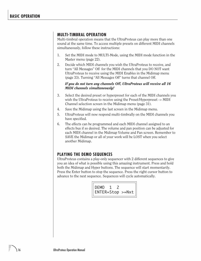
PLAYING THE DEMO SEQUENCESUltraProteus contains a play-only sequencer with 2 different sequences to give
you an idea of what is possible using this amazing instrument. Press and hold
both the Midimap and Hyper buttons. The sequence will start momentarily.
Press the Enter button to stop the sequence. Press the right cursor button to
advance to the next sequence. Sequences will cycle automatically.
DEMO 1 2ENTER=Stop >=Nxt
UltraProteus MASTER MENU

18 UltraProteus Operation Manual
19Chapter 3: Master Menu
MASTER MENU
The Master menu contains functions that affect the overall operation ofUltraProteus. For example, changing the Master Tune will change the tuning ofall the presets, not just the one currently displayed.
To enable the Master menuPress the Master button, lighting the LED. The current screen will be theone most recently selected since powering up UltraProteus. The Cursorwill appear underneath the first character of the screen heading on lineone.
To select a new screenPress the Home/Enter button or press the Cursor key repeatedly until thecursor is underneath the screen title heading. Rotate the data entrycontrol to select another screen.
To modify a parameterPress the Cursor button repeatedly (or hold the right cursor key whileturning the data entry control) until the cursor is underneath the param-eter value. Rotate the data entry control to change the value.
To return to the main screenPress the Master button, turning off the LED.
MASTER MENU FUNCTIONS
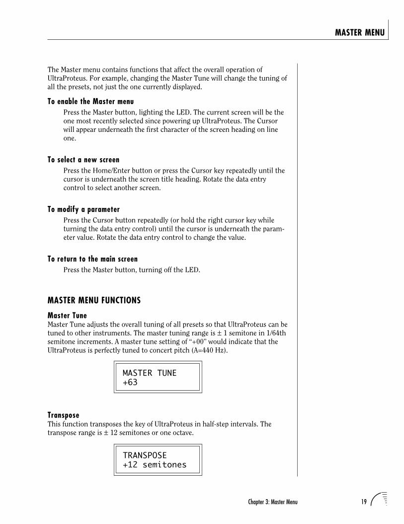
Master TuneMaster Tune adjusts the overall tuning of all presets so that UltraProteus can betuned to other instruments. The master tuning range is ± 1 semitone in 1/64thsemitone increments. A master tune setting of “+00” would indicate that theUltraProteus is perfectly tuned to concert pitch (A=440 Hz).
MASTER TUNE+63
TransposeThis function transposes the key of UltraProteus in half-step intervals. Thetranspose range is ± 12 semitones or one octave.
TRANSPOSE+12 semitones
20 UltraProteus Operation Manual
MASTER MENU
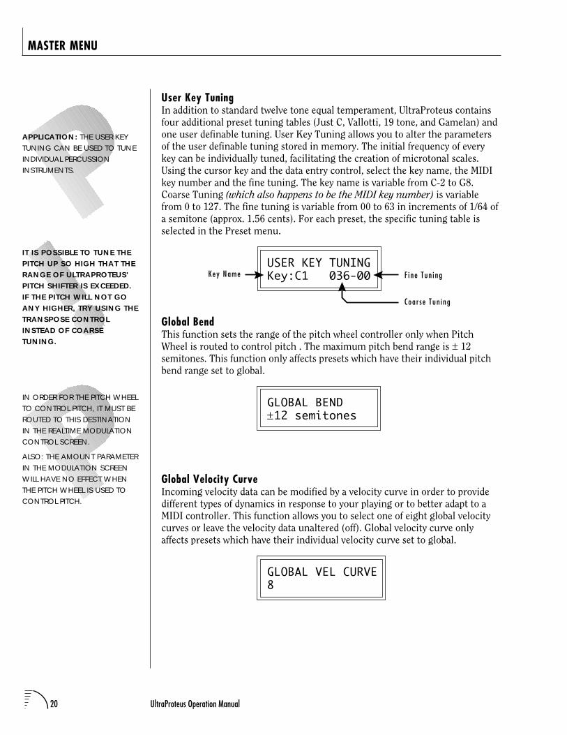
User Key TuningIn addition to standard twelve tone equal temperament, UltraProteus containsfour additional preset tuning tables (Just C, Vallotti, 19 tone, and Gamelan) andone user definable tuning. User Key Tuning allows you to alter the parametersof the user definable tuning stored in memory. The initial frequency of everykey can be individually tuned, facilitating the creation of microtonal scales.Using the cursor key and the data entry control, select the key name, the MIDIkey number and the fine tuning. The key name is variable from C-2 to G8.Coarse Tuning (which also happens to be the MIDI key number) is variablefrom 0 to 127. The fine tuning is variable from 00 to 63 in increments of 1/64 ofa semitone (approx. 1.56 cents). For each preset, the specific tuning table isselected in the Preset menu.
USER KEY TUNINGKey:C1 036-00
Global BendThis function sets the range of the pitch wheel controller only when PitchWheel is routed to control pitch . The maximum pitch bend range is ± 12semitones. This function only affects presets which have their individual pitchbend range set to global.
GLOBAL BEND±12 semitones
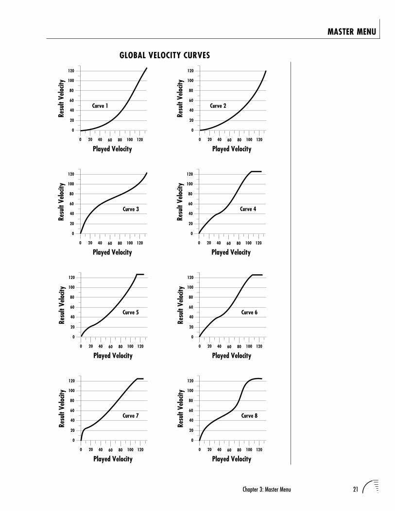
Global Velocity CurveIncoming velocity data can be modified by a velocity curve in order to providedifferent types of dynamics in response to your playing or to better adapt to aMIDI controller. This function allows you to select one of eight global velocitycurves or leave the velocity data unaltered (off). Global velocity curve onlyaffects presets which have their individual velocity curve set to global.
GLOBAL VEL CURVE8
APPLICATION: THE USER KEYTUNING CAN BE USED TO TUNEINDIVIDUAL PERCUSSIONINSTRUMENTS.
IT IS POSSIBLE TO TUNE THEPITCH UP SO HIGH THAT THERANGE OF ULTRAPROTEUS'PITCH SHIFTER IS EXCEEDED.IF THE PITCH WILL NOT GOANY HIGHER, TRY USING THETRANSPOSE CONTROLINSTEAD OF COARSETUNING.
IN ORDER FOR THE PITCH WHEELTO CONTROL PITCH, IT MUST BEROUTED TO THIS DESTINATIONIN THE REALTIME MODULATIONCONTROL SCREEN.
ALSO: THE AMOUNT PARAMETERIN THE MODULATION SCREENWILL HAVE NO EFFECT WHENTHE PITCH WHEEL IS USED TOCONTROL PITCH.
Key Name F ine Tun i ng
Coa r s e Tun i ng
21Chapter 3: Master Menu
MASTER MENU
GLOBAL VELOCITY CURVES
Curve 1
0
20
40
60
80
100
120
0 20 40 60 80 100
Played Velocity120
Resu
lt Ve
locit
y
Curve 2
0
20
40
60
80
100
120
0 20 40 60 80 100
Played Velocity120
Resu
lt Ve
locit
y
Curve 3
0
20
40
60
80
100
120
0 20 40 60 80 100
Played Velocity120
Resu
lt Ve
locit
y
0
20
40
60
80
100
120
0 20 40 60 80 100
Played Velocity120
Resu
lt Ve
locit
y
Curve 5
0
20
40
60
80
100
120
0 20 40 60 80 100
Played Velocity120
Resu
lt Ve
locit
y
Curve 6
0
20
40
60
80
100
120
0 20 40 60 80 100
Played Velocity120
Resu
lt Ve
locit
y
Curve 4
0
20
40
60
80
100
120
0 20 40 60 80 100
Played Velocity120
Resu
lt Ve
locit
y
Curve 7
0
20
40
60
80
100
120
0 20 40 60 80 100
Played Velocity120
Resu
lt Ve
locit
y
Curve 8
22 UltraProteus Operation Manual
MASTER MENU
MIDI ModeThis function selects one of the four MIDI receive modes and the MIDI systemexclusive ID number.
Omni modeUltraProteus responds to note information on all MIDI channels and playsthe preset currently displayed in the main screen.
Poly modeUltraProteus only responds to note information received on the currentlyselected MIDI channel (the “basic channel”, displayed on the main screen)and plays that channel’s associated preset.
Multi modeUltraProteus responds to data on any combination of MIDI channels andplays the specific preset associated with each of the MIDI channels.
Mono modeUltraProteus responds to data on any combination of MIDI channels butplays each channel monophonically. If a new note on a channel is playedbefore the last note is released, the envelopes will not be retriggered. Monomode is particularly useful with alternate controllers such as MIDI guitars,etc.
Device IDThis function allows an external programming unit to distinguish betweenmultiple UltraProteus units. In the case of multiple UltraProteus units,each unit should have a different device ID number.
MIDI MODE IDOmni 00
MIDI Mode ChangeThis function selects whether or not MIDI mode change commands are ac-cepted or ignored when received over MIDI (see MIDI Mode).
MIDI MODE CHANGEDisabled
WARNING: MIDI SYSEX DATAWILL NOT BE TRANSFERREDBETWEEN TWOULTRAPROTEUS UNITSUNLESS THE ID NUMBERS OFBOTH UNITS MATCH.
MONO MODE FUNCTIONS THESAME WAY AS SOLO “WIND”MODE.
23Chapter 3: Master Menu
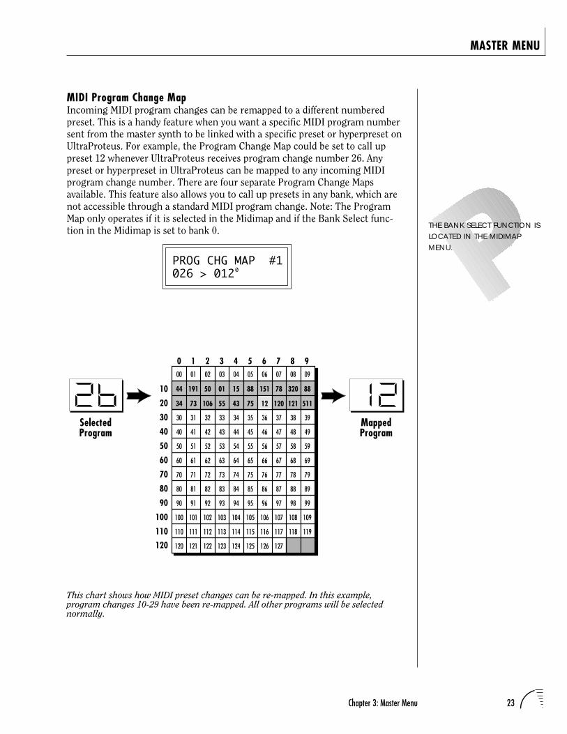
MIDI Program Change MapIncoming MIDI program changes can be remapped to a different numberedpreset. This is a handy feature when you want a specific MIDI program numbersent from the master synth to be linked with a specific preset or hyperpreset onUltraProteus. For example, the Program Change Map could be set to call uppreset 12 whenever UltraProteus receives program change number 26. Anypreset or hyperpreset in UltraProteus can be mapped to any incoming MIDIprogram change number. There are four separate Program Change Mapsavailable. This feature also allows you to call up presets in any bank, which arenot accessible through a standard MIDI program change. Note: The ProgramMap only operates if it is selected in the Midimap and if the Bank Select func-tion in the Midimap is set to bank 0.
PROG CHG MAP #1026 > 012
MASTER MENU
THE BANK SELECT FUNCTION ISLOCATED IN THE MIDIMAPMENU.
This chart shows how MIDI preset changes can be re-mapped. In this example,program changes 10-29 have been re-mapped. All other programs will be selectednormally.
0
SelectedProgram
MappedProgram
0 1 2 3 4 5 6 7 8 9
10
20
30
40
50
60
70
80
90
100
110
120
00 01 02 03 04 05 06 07 08 09
30 31 32 33 34 35 36 37 38 39
40 41 42 43 44 45 46 47 48 49
50 51 52 53 54 55 56 57 58 59
60 61 62 63 64 65 66 67 68 69
70 71 72 73 74 75 76 77 78 79
80 81 82 83 84 85 86 87 88 89
90 91 92 93 94 95 96 97 98 99
100 101 102 103 104 105 106 107 108 109
110 111 112 113 114 115 116 117 118 119
120 121 122 123 124 125 126 127
44 191 50 01 15 88 151 78 320 88
34 73 106 55 43 75 120 121 51112
24 UltraProteus Operation Manual
MASTER MENU
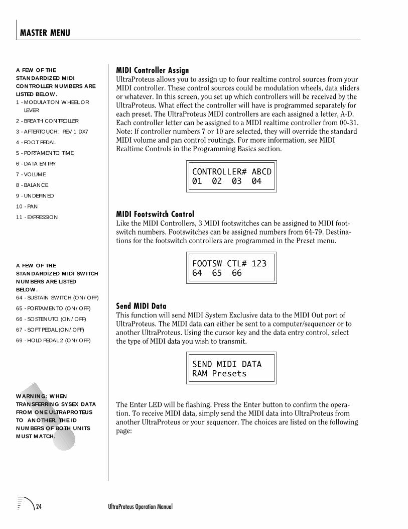
MIDI Controller AssignUltraProteus allows you to assign up to four realtime control sources from yourMIDI controller. These control sources could be modulation wheels, data slidersor whatever. In this screen, you set up which controllers will be received by theUltraProteus. What effect the controller will have is programmed separately foreach preset. The UltraProteus MIDI controllers are each assigned a letter, A-D.Each controller letter can be assigned to a MIDI realtime controller from 00-31.Note: If controller numbers 7 or 10 are selected, they will override the standardMIDI volume and pan control routings. For more information, see MIDIRealtime Controls in the Programming Basics section.
CONTROLLER# ABCD01 02 03 04
MIDI Footswitch ControlLike the MIDI Controllers, 3 MIDI footswitches can be assigned to MIDI foot-switch numbers. Footswitches can be assigned numbers from 64-79. Destina-tions for the footswitch controllers are programmed in the Preset menu.
FOOTSW CTL# 12364 65 66
Send MIDI DataThis function will send MIDI System Exclusive data to the MIDI Out port ofUltraProteus. The MIDI data can either be sent to a computer/sequencer or toanother UltraProteus. Using the cursor key and the data entry control, selectthe type of MIDI data you wish to transmit.
SEND MIDI DATARAM Presets
The Enter LED will be flashing. Press the Enter button to confirm the opera-tion. To receive MIDI data, simply send the MIDI data into UltraProteus fromanother UltraProteus or your sequencer. The choices are listed on the followingpage:
A FEW OF THESTANDARDIZED MIDICONTROLLER NUMBERS ARELISTED BELOW.1 - MODULATION WHEEL OR
LEVER
2 - BREATH CONTROLLER
3 - AFTERTOUCH: REV 1 DX7
4 - FOOT PEDAL
5 - PORTAMENTO TIME
6 - DATA ENTRY
7 - VOLUME
8 - BALANCE
9 - UNDEFINED
10 - PAN
11 - EXPRESSION
A FEW OF THESTANDARDIZED MIDI SWITCHNUMBERS ARE LISTEDBELOW.64 - SUSTAIN SWITCH (ON/OFF)
65 - PORTAMENTO (ON/OFF)
66 - SOSTENUTO (ON/OFF)
67 - SOFT PEDAL (ON/OFF)
69 - HOLD PEDAL 2 (ON/OFF)
WARNING: WHENTRANSFERRING SYSEX DATAFROM ONE ULTRAPROTEUSTO ANOTHER, THE IDNUMBERS OF BOTH UNITSMUST MATCH.
25Chapter 3: Master Menu
MASTER MENU
RAM Presets ............................................ Transmits all the user RAM presets.
ROM Presets ...................................... Transmits all the factory ROM presets.
Card Presets ...................................... Transmits all the memory card presets.
RAM Hypers .................................. Transmits all the user RAM hyperpresets.
Card Hypers ............................ Transmits all the memory card hyperpresets.
RAM MIDI Maps ......................................... Transmits all the user MIDI maps.
Card MIDI Maps ........................Transmits all the memory card MIDI maps.
Program Change Maps ..................Transmits all the program change maps.
Master Settings .....................Transmits all parameters in the Master menuexcept tuning table, program change map & viewing angle.
The “scratch” Midimap is also transmitted.
Tuning Table ......................................... Transmits only the user tuning table.
All RAM Data .................... Transmits all the user RAM data in the machine.
Individual Program ..... Transmits only the specified preset or hyperpreset.
Individual Midimap ............................ Transmits only the specified midimap.
Individual Program Change Map ...... Transmits the specified program map.
When Individual Programs, Midimaps or Program Change Maps are received viaSysEx, they are placed in their proper locations.
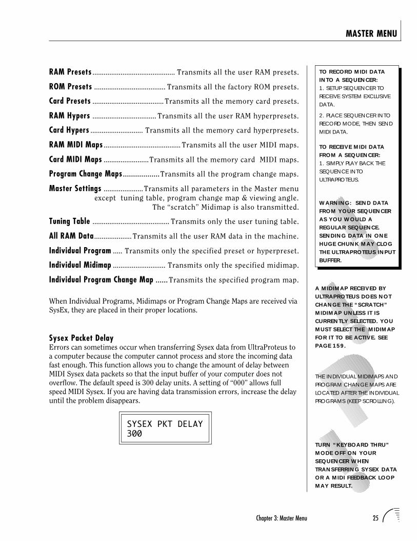
Sysex Packet DelayErrors can sometimes occur when transferring Sysex data from UltraProteus toa computer because the computer cannot process and store the incoming datafast enough. This function allows you to change the amount of delay betweenMIDI Sysex data packets so that the input buffer of your computer does notoverflow. The default speed is 300 delay units. A setting of “000” allows fullspeed MIDI Sysex. If you are having data transmission errors, increase the delayuntil the problem disappears.
SYSEX PKT DELAY300
A MIDIMAP RECEIVED BYULTRAPROTEUS DOES NOTCHANGE THE “SCRATCH”MIDIMAP UNLESS IT ISCURRENTLY SELECTED. YOUMUST SELECT THE MIDIMAPFOR IT TO BE ACTIVE. SEEPAGE 159.
THE INDIVIDUAL MIDIMAPS ANDPROGRAM CHANGE MAPS ARELOCATED AFTER THE INDIVIDUALPROGRAMS (KEEP SCROLLING).
TURN “KEYBOARD THRU”MODE OFF ON YOURSEQUENCER WHENTRANSFERRING SYSEX DATAOR A MIDI FEEDBACK LOOPMAY RESULT.
TO RECORD MIDI DATAINTO A SEQUENCER:1. SETUP SEQUENCER TORECEIVE SYSTEM EXCLUSIVEDATA.
2. PLACE SEQUENCER INTORECORD MODE, THEN SENDMIDI DATA.
TO RECEIVE MIDI DATAFROM A SEQUENCER:1. SIMPLY PLAY BACK THESEQUENCE INTOULTRAPROTEUS.
WARNING: SEND DATAFROM YOUR SEQUENCERAS YOU WOULD AREGULAR SEQUENCE.SENDING DATA IN ONEHUGE CHUNK MAY CLOGTHE ULTRAPROTEUS INPUTBUFFER.
26 UltraProteus Operation Manual
MASTER MENU
Proteus SysexWhen this function is turned On, Proteus presets can be transferred over MIDIinto UltraProteus. It also allows the use of Proteus patch editing programs.Instrument numbers will be translated into UltraProteus equivalents. Param-eters which are unique to UltraProteus will, of course, NOT be transferred. Thisfunction defaults to Off to avoid unplanned conflicts with Proteus Sysex trans-fers.
PROTEUS SYSEXOff
Auto SelectWhen editing a parameter which involves the keyboard, such as a zone range,the parameter can be automatically selected simply by playing the keyboard.This is a handy feature for “power programmers”, but can sometimes be confus-ing. Therefore, Auto-Select can be turned On or Off. Auto-Select affects thefollowing parameters: User Key Tuning, Zone Select, Key Range, Midimap,Preset & Hyperpreset Naming, Cross-switch Point, Keyboard Center.
AUTO-SELECTOff
CompareThis function turns the Compare feature (accessed by pressing the Presetbutton when editing) On or Off. If Compare is turned On, changes made viaMIDI SysEx will not be heard except when the Preset menu is enabled.
COMPAREOn
Viewing AngleThis function allows you to change the viewing angle of the display so that itmay be easily read from either above or below. The angle is adjustable from +7to -8. Positive values will make the display easier to read when viewed fromabove. Negative values make the display easier to read from below.
VIEWING ANGLE+7
IF ULTRAPROTEUS DOES NOTRESPOND TO EXTERNALPRESET EDITORS, TURN THECOMPARE FUNCTION OFF.
27Chapter 4: Midimap Menu
UltraProteus MIDIMAP MENU

28 UltraProteus Operation Manual
29Chapter 4: Midimap Menu
MIDI CHANNEL 1
MIXSELECT
PROGRAM
FX A
FX B
Main
Sub 1
VOLUME
PAN
MIDIENABLES
BANKSELECT
EFFECTA
AMOUNT
OUTPUT
EFFECTB
16 Channels
MIDIMAP
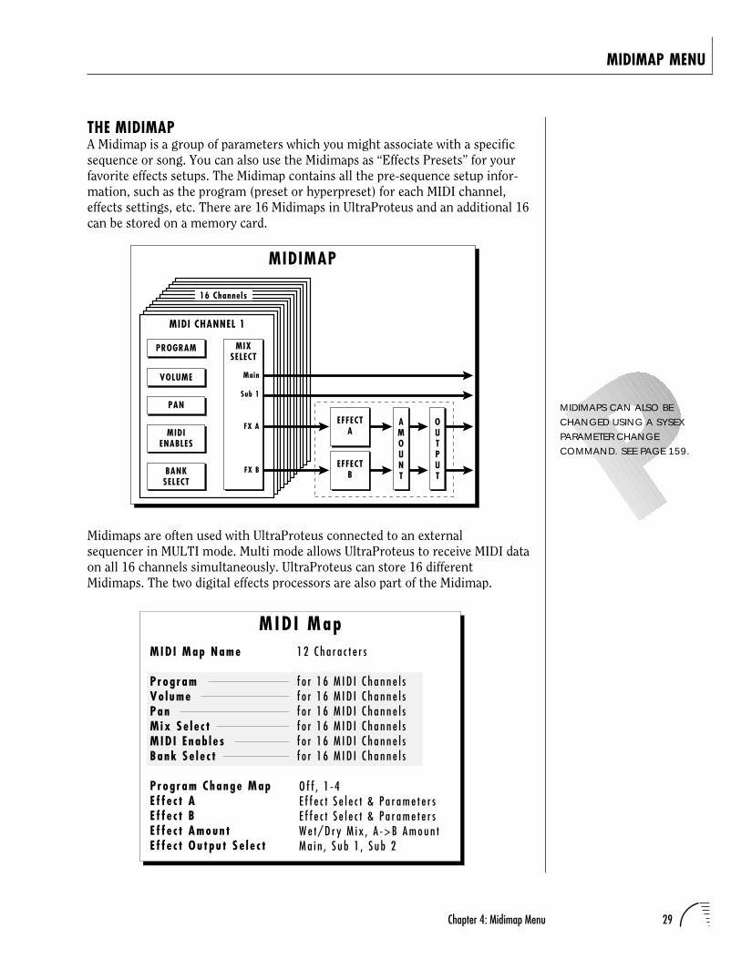
THE MIDIMAPA Midimap is a group of parameters which you might associate with a specificsequence or song. You can also use the Midimaps as “Effects Presets” for yourfavorite effects setups. The Midimap contains all the pre-sequence setup infor-mation, such as the program (preset or hyperpreset) for each MIDI channel,effects settings, etc. There are 16 Midimaps in UltraProteus and an additional 16can be stored on a memory card.
MIDIMAP MENU
Midimaps are often used with UltraProteus connected to an externalsequencer in MULTI mode. Multi mode allows UltraProteus to receive MIDI dataon all 16 channels simultaneously. UltraProteus can store 16 differentMidimaps. The two digital effects processors are also part of the Midimap.
MIDIMAPS CAN ALSO BECHANGED USING A SYSEXPARAMETER CHANGECOMMAND. SEE PAGE 159.
MID I Map Name
P rog ramVo l umePanM ix Se l e c tM ID I E nab l e sBank Se l e c t
P r og r am Change MapE f f e c t AE f f e c t BE f f e c t Amoun tE f f e c t Ou tpu t S e l e c t
f o r 1 6 M I D I C h a n n e l sf o r 1 6 M I D I C h a n n e l sf o r 1 6 M I D I C h a n n e l sf o r 1 6 M I D I C h a n n e l sf o r 1 6 M I D I C h a n n e l sf o r 1 6 M I D I C h a n n e l s
MID I Map
O f f , 1 - 4E f f e c t S e l e c t & P a r a m e t e r sE f f e c t S e l e c t & P a r a m e t e r sW e t / D r y M i x , A - > B A m o u n tM a i n , S u b 1 , S u b 2
1 2 C h a r a c t e r s
30 UltraProteus Operation Manual
MIDIMAP MENU
To enable the Midimap menuPress the Midimap button, lighting the LED. The current screen will bethe one most recently selected since powering up UltraProteus. The cursorwill appear underneath the first character of the screen heading on lineone.
To select a MidimapPress the Home/Enter button or press the cursor key repeatedly until thecursor is underneath the screen title heading. The first screen in the list is“Midimap Select”. Move the cursor to the lower line of the display and usethe data entry control to select the desired Midimap. The Home/Enter LEDwill be flashing. Press Home/Enter to load the Midimap.
To select a new screenPress the Home/Enter button or press the cursor key repeatedly until thecursor is underneath the screen title heading. Rotate the data entrycontrol to select another screen.
To modify a parameterPress the cursor button repeatedly (or hold the cursor key while turningthe data entry control) until the cursor is underneath the parameter value.Rotate the data entry control to change the value.
To return to Program Select modePress the Midimap button, turning off the LED.
MIDIMAP MENU FUNCTIONS
Midimap SelectThis is where you select one of the 16 Midimaps. You can use the Midimaps tosetup a particular sequence or song. Position the cursor under the Midimapnumber and use the data entry control to select the Midimap. The Home/EnterLED will be flashing. You MUST press Enter to load the Midimap.
MIDIMAP SELECTM00 Cool FX
SELECTING A NEW MIDIMAPWILL OVERWRITE THE“CURRENT” OR “SCRATCH”MIDIMAP.
31Chapter 4: Midimap Menu
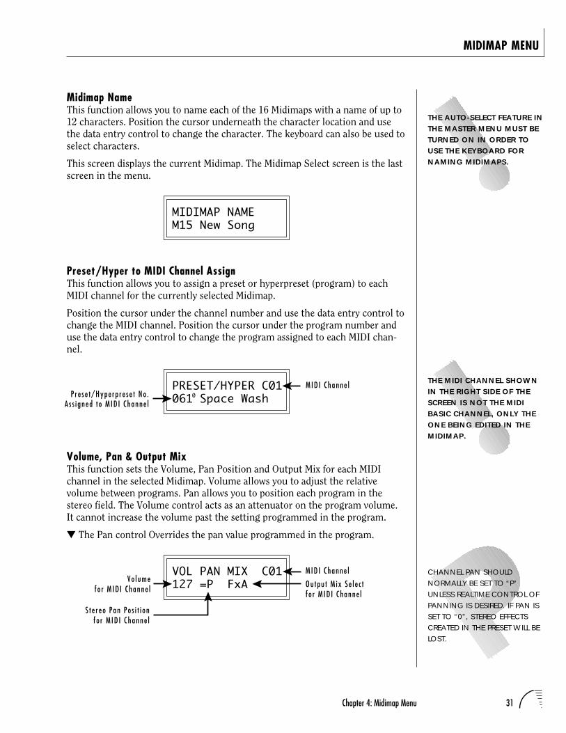
Midimap NameThis function allows you to name each of the 16 Midimaps with a name of up to12 characters. Position the cursor underneath the character location and usethe data entry control to change the character. The keyboard can also be used toselect characters.
This screen displays the current Midimap. The Midimap Select screen is the lastscreen in the menu.
MIDIMAP NAMEM15 New Song
Preset/Hyper to MIDI Channel AssignThis function allows you to assign a preset or hyperpreset (program) to eachMIDI channel for the currently selected Midimap.
Position the cursor under the channel number and use the data entry control tochange the MIDI channel. Position the cursor under the program number anduse the data entry control to change the program assigned to each MIDI chan-nel.
PRESET/HYPER C01061 Space Wash
Volume, Pan & Output MixThis function sets the Volume, Pan Position and Output Mix for each MIDIchannel in the selected Midimap. Volume allows you to adjust the relativevolume between programs. Pan allows you to position each program in thestereo field. The Volume control acts as an attenuator on the program volume.It cannot increase the volume past the setting programmed in the program.
The Pan control Overrides the pan value programmed in the program.
VOL PAN MIX C01127 =P FxA
MIDIMAP MENU
0MID I Channe l
P r e s e t/Hype rp re se t No .A s s i gned t o M ID I Channe l
CHANNEL PAN SHOULDNORMALLY BE SET TO “P”UNLESS REALTIME CONTROL OFPANNING IS DESIRED. IF PAN ISSET TO “0”, STEREO EFFECTSCREATED IN THE PRESET WILL BELOST.
THE MIDI CHANNEL SHOWNIN THE RIGHT SIDE OF THESCREEN IS NOT THE MIDIBASIC CHANNEL, ONLY THEONE BEING EDITED IN THEMIDIMAP.
THE AUTO-SELECT FEATURE INTHE MASTER MENU MUST BETURNED ON IN ORDER TOUSE THE KEYBOARD FORNAMING MIDIMAPS.
Vo lumefo r M ID I Channe l
M ID I Channe l
Ou tpu t M ix Se l e c tf o r M ID I Channe l
S t e r eo Pan Po s i t i onfo r M ID I Channe l
32 UltraProteus Operation Manual
MIDIMAP MENU
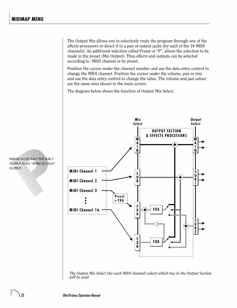
The Output Mix allows you to selectively route the program through one of theeffects processors or direct it to a pair of output jacks (for each of the 16 MIDIchannels). An additional selection called Preset or “P”, allows the selection to bemade in the preset (Mix Output). Thus effects and outputs can be selectedaccording to MIDI channel or by preset.
Position the cursor under the channel number and use the data entry control tochange the MIDI channel. Position the cursor under the volume, pan or mixand use the data entry control to change the value. The volume and pan valuesare the same ones shown in the main screen.
The diagram below shows the function of Output Mix Select.
The Output Mix Select (for each MIDI channel) selects which bus in the Output Sectionwill be used.
PLEASE NOTE THAT THE SUB 2OUTPUT IS AN “EFFECTS ONLY”OUTPUT.
MAIN
SUB
FXA
FXB
SUB1
FXA
FXB
MAIN
OUTPUT SECTION& EFFECTS PROCESSORS
MIDI Channe l 1
MIDI Channe l 2
MIDI Channe l 3
MIDI Channe l 16
SUB2
MixSe lec t
OutputSe lec t
Preset= FXA
33Chapter 4: Midimap Menu
MIDIMAP MENU
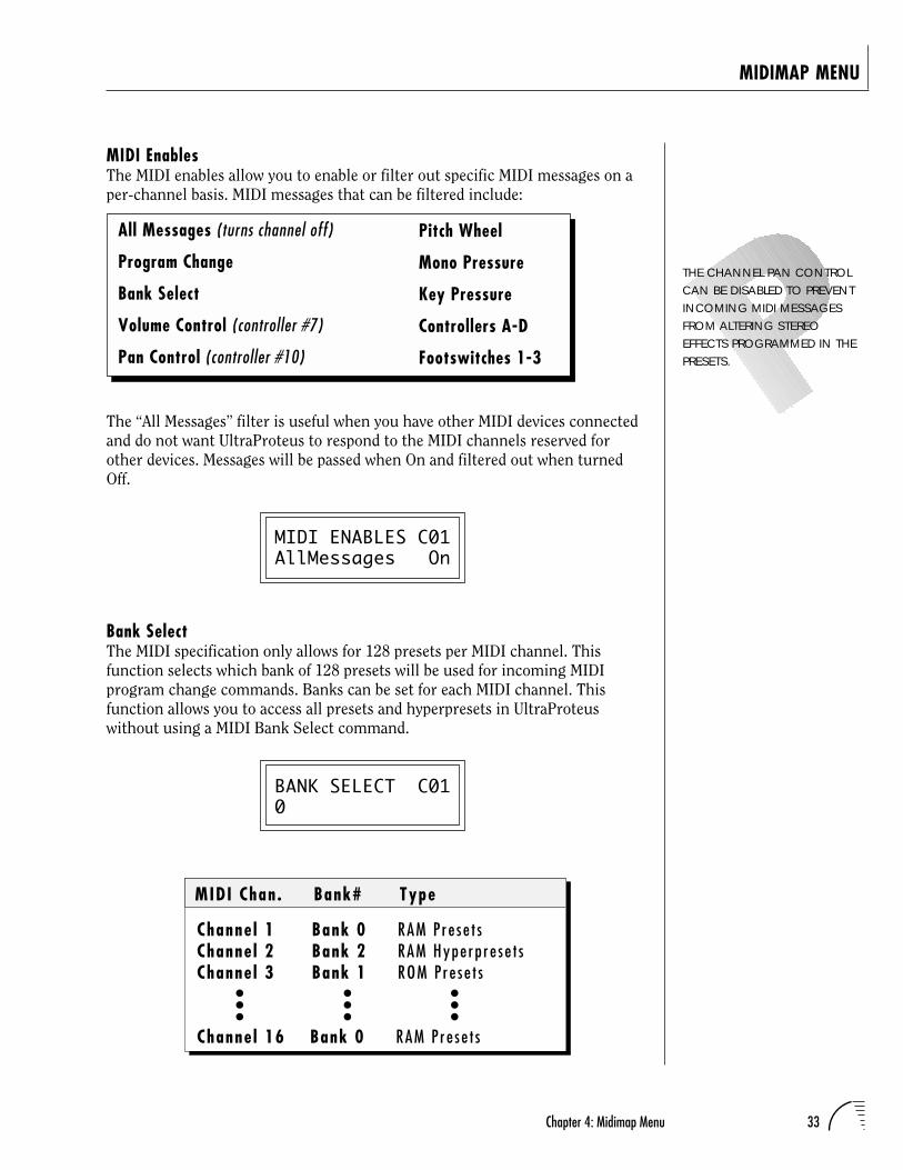
MIDI EnablesThe MIDI enables allow you to enable or filter out specific MIDI messages on aper-channel basis. MIDI messages that can be filtered include:
All Messages (turns channel off)
Program Change
Bank Select
Volume Control (controller #7)
Pan Control (controller #10)
THE CHANNEL PAN CONTROLCAN BE DISABLED TO PREVENTINCOMING MIDI MESSAGESFROM ALTERING STEREOEFFECTS PROGRAMMED IN THEPRESETS.
The “All Messages” filter is useful when you have other MIDI devices connectedand do not want UltraProteus to respond to the MIDI channels reserved forother devices. Messages will be passed when On and filtered out when turnedOff.
MIDI ENABLES C01AllMessages On
Bank SelectThe MIDI specification only allows for 128 presets per MIDI channel. Thisfunction selects which bank of 128 presets will be used for incoming MIDIprogram change commands. Banks can be set for each MIDI channel. Thisfunction allows you to access all presets and hyperpresets in UltraProteuswithout using a MIDI Bank Select command.
BANK SELECT C010
Pitch Wheel
Mono Pressure
Key Pressure
Controllers A-D
Footswitches 1-3
Channe l 1 Bank 0 RAM P re se t sChanne l 2 Bank 2 RAM Hype rp re se t sChanne l 3 Bank 1 ROM P re se t s
Channe l 16 Bank 0 RAM P re se t s
MIDI Chan . Bank# Type
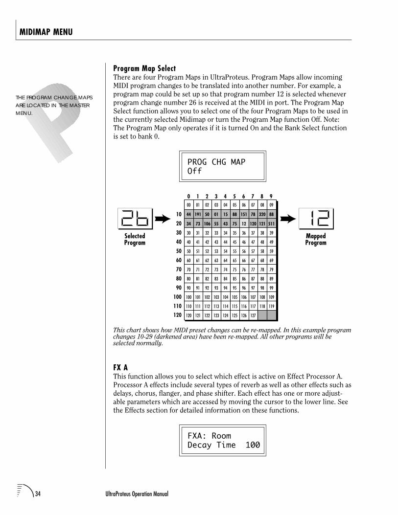
34 UltraProteus Operation Manual
MIDIMAP MENU
Program Map SelectThere are four Program Maps in UltraProteus. Program Maps allow incomingMIDI program changes to be translated into another number. For example, aprogram map could be set up so that program number 12 is selected wheneverprogram change number 26 is received at the MIDI in port. The Program MapSelect function allows you to select one of the four Program Maps to be used inthe currently selected Midimap or turn the Program Map function Off. Note:The Program Map only operates if it is turned On and the Bank Select functionis set to bank 0.
PROG CHG MAPOff
This chart shows how MIDI preset changes can be re-mapped. In this example programchanges 10-29 (darkened area) have been re-mapped. All other programs will beselected normally.
FX AThis function allows you to select which effect is active on Effect Processor A.Processor A effects include several types of reverb as well as other effects such asdelays, chorus, flanger, and phase shifter. Each effect has one or more adjust-able parameters which are accessed by moving the cursor to the lower line. Seethe Effects section for detailed information on these functions.
FXA: RoomDecay Time 100
THE PROGRAM CHANGE MAPSARE LOCATED IN THE MASTERMENU.
SelectedProgram
MappedProgram
0 1 2 3 4 5 6 7 8 9
10
20
30
40
50
60
70
80
90
100
110
120
00 01 02 03 04 05 06 07 08 09
30 31 32 33 34 35 36 37 38 39
40 41 42 43 44 45 46 47 48 49
50 51 52 53 54 55 56 57 58 59
60 61 62 63 64 65 66 67 68 69
70 71 72 73 74 75 76 77 78 79
80 81 82 83 84 85 86 87 88 89
90 91 92 93 94 95 96 97 98 99
100 101 102 103 104 105 106 107 108 109
110 111 112 113 114 115 116 117 118 119
120 121 122 123 124 125 126 127
44 191 50 01 15 88 151 78 320 88
34 73 106 55 43 75 120 121 51112
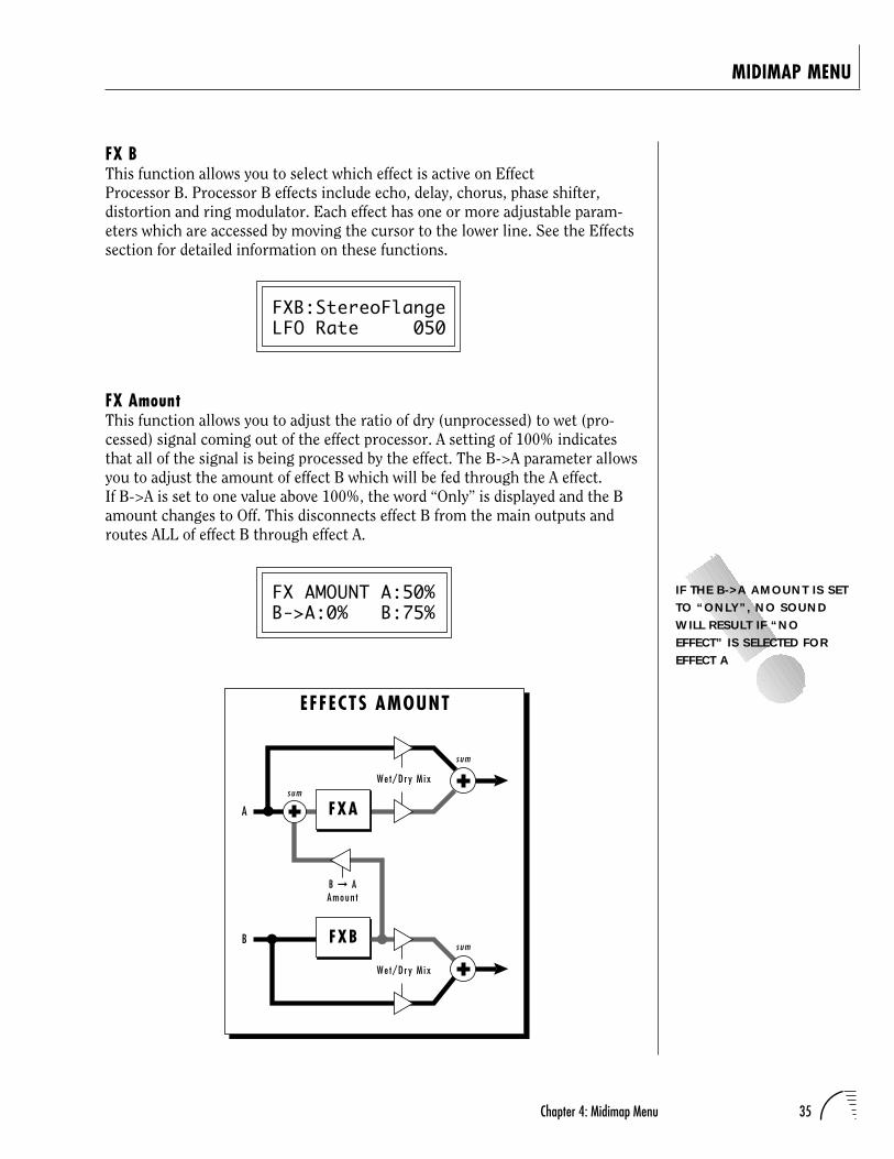
35Chapter 4: Midimap Menu
MIDIMAP MENU
FX BThis function allows you to select which effect is active on EffectProcessor B. Processor B effects include echo, delay, chorus, phase shifter,distortion and ring modulator. Each effect has one or more adjustable param-eters which are accessed by moving the cursor to the lower line. See the Effectssection for detailed information on these functions.
FXB:StereoFlangeLFO Rate 050
FX AmountThis function allows you to adjust the ratio of dry (unprocessed) to wet (pro-cessed) signal coming out of the effect processor. A setting of 100% indicatesthat all of the signal is being processed by the effect. The B->A parameter allowsyou to adjust the amount of effect B which will be fed through the A effect.If B->A is set to one value above 100%, the word “Only” is displayed and the Bamount changes to Off. This disconnects effect B from the main outputs androutes ALL of effect B through effect A.
FX AMOUNT A:50%B->A:0% B:75%
IF THE B->A AMOUNT IS SETTO “ONLY”, NO SOUNDWILL RESULT IF “NOEFFECT” IS SELECTED FOREFFECT A
FXA
FXB
EFFECTS AMOUNT
Wet/Dry M ix
We t/Dry M ix
s um
sum
sum
B AAmoun t
A
B
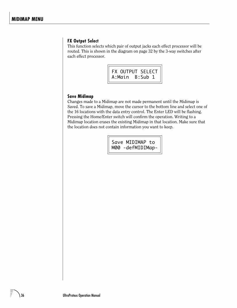
36 UltraProteus Operation Manual
FX Output SelectThis function selects which pair of output jacks each effect processor will berouted. This is shown in the diagram on page 32 by the 3-way switches aftereach effect processor.
FX OUTPUT SELECTA:Main B:Sub 1
Save MidimapChanges made to a Midimap are not made permanent until the Midimap isSaved. To save a Midimap, move the cursor to the bottom line and select one ofthe 16 locations with the data entry control. The Enter LED will be flashing.Pressing the Home/Enter switch will confirm the operation. Writing to aMidimap location erases the existing Midimap in that location. Make sure thatthe location does not contain information you want to keep.
Save MIDIMAP toM00 -defMIDIMap-
MIDIMAP MENU
37Chapter 5: Effects Section
UltraProteus EFFECTS SECTION

38 UltraProteus Operation Manual
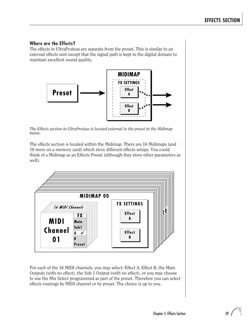
39Chapter 5: Effects Section
Where are the Effects?The effects in UltraProteus are separate from the preset. This is similar to an
external effects unit except that the signal path is kept in the digital domain to
maintain excellent sound quality.
The effects section is located within the Midimap. There are 16 Midimaps (and
16 more on a memory card) which store different effects setups. You could
think of a Midimap as an Effects Preset (although they store other parameters as
well).
The Effects section in UltraProteus is located external to the preset in the Midimapmenu.
Preset EffectA
FX SETTINGS
EffectB
MIDIMAP
EFFECTS SECTION
Ef fec tA
FX SETT INGS
Effec tB
MIDIMAP 00
16MainSub1ABPreset
MIDIChanne l
01
FX
16 MIDI Channe ls
For each of the 16 MIDI channels, you may select: Effect A, Effect B, the Main
Outputs (with no effect), the Sub 1 Output (with no effect), or you may choose
to use the Mix Select programmed as part of the preset. Therefore you can select
effects routings by MIDI channel or by preset. The choice is up to you.
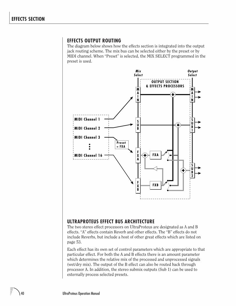
40 UltraProteus Operation Manual
EFFECTS OUTPUT ROUTINGThe diagram below shows how the effects section is integrated into the output
jack routing scheme. The mix bus can be selected either by the preset or by
MIDI channel. When “Preset” is selected, the MIX SELECT programmed in the
preset is used.
EFFECTS SECTION
MAIN
SUB
FXA
FXB
SUB1
FXA
FXB
MAIN
OUTPUT SECTION& EFFECTS PROCESSORS
MIDI Channe l 1
MIDI Channe l 2
MIDI Channe l 3
MIDI Channe l 16
SUB2
MixSe lec t
OutputSe lec t
Preset= FXA
ULTRAPROTEUS EFFECT BUS ARCHITECTUREThe two stereo effect processors on UltraProteus are designated as A and B
effects. “A” effects contain Reverb and other effects. The “B” effects do not
include Reverbs, but include a host of other great effects which are listed on
page 53.
Each effect has its own set of control parameters which are appropriate to that
particular effect. For both the A and B effects there is an amount parameter
which determines the relative mix of the processed and unprocessed signals
(wet/dry mix). The output of the B effect can also be routed back through
processor A. In addition, the stereo submix outputs (Sub 1) can be used to
externally process selected presets.
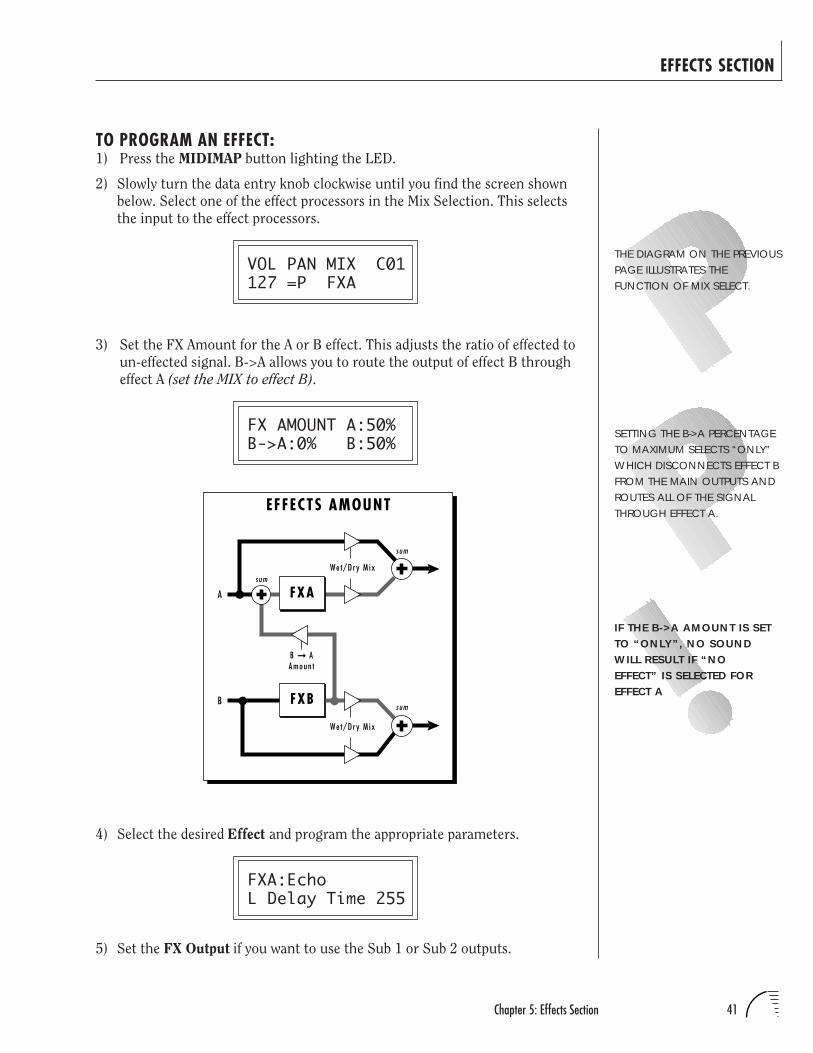
41Chapter 5: Effects Section
EFFECTS SECTION
TO PROGRAM AN EFFECT:1) Press the MIDIMAP button lighting the LED.
2) Slowly turn the data entry knob clockwise until you find the screen shown
below. Select one of the effect processors in the Mix Selection. This selects
the input to the effect processors.
VOL PAN MIX C01127 =P FXA
3) Set the FX Amount for the A or B effect. This adjusts the ratio of effected to
un-effected signal. B->A allows you to route the output of effect B through
effect A (set the MIX to effect B).
FX AMOUNT A:50%B->A:0% B:50%
FXA
FXB
EFFECTS AMOUNT
Wet/Dry M ix
We t/Dry M ix
sum
sum
sum
B AAmoun t
A
B
4) Select the desired Effect and program the appropriate parameters.
FXA:EchoL Delay Time 255
5) Set the FX Output if you want to use the Sub 1 or Sub 2 outputs.
IF THE B->A AMOUNT IS SETTO “ONLY”, NO SOUNDWILL RESULT IF “NOEFFECT” IS SELECTED FOREFFECT A
THE DIAGRAM ON THE PREVIOUSPAGE ILLUSTRATES THEFUNCTION OF MIX SELECT.
SETTING THE B->A PERCENTAGETO MAXIMUM SELECTS “ONLY”WHICH DISCONNECTS EFFECT BFROM THE MAIN OUTPUTS ANDROUTES ALL OF THE SIGNALTHROUGH EFFECT A.
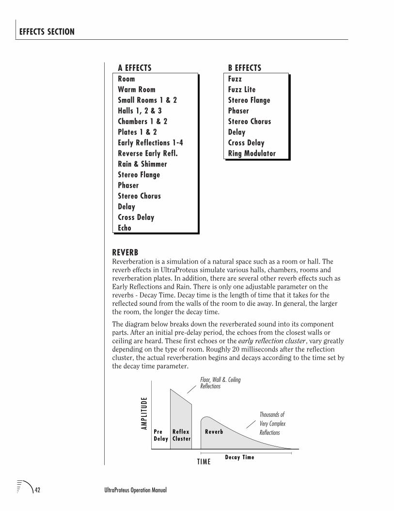
42 UltraProteus Operation Manual
EFFECTS SECTION
B EFFECTSFuzzFuzz LiteStereo FlangePhaserStereo ChorusDelayCross DelayRing Modulator
Floor, Wall &. CeilingReflections
Thousands ofVery ComplexReflections
A EFFECTSRoomWarm RoomSmall Rooms 1 & 2Halls 1, 2 & 3Chambers 1 & 2Plates 1 & 2Early Reflections 1-4Reverse Early Refl.Rain & ShimmerStereo FlangePhaserStereo ChorusDelayCross DelayEcho
REVERBReverberation is a simulation of a natural space such as a room or hall. The
reverb effects in UltraProteus simulate various halls, chambers, rooms and
reverberation plates. In addition, there are several other reverb effects such as
Early Reflections and Rain. There is only one adjustable parameter on the
reverbs - Decay Time. Decay time is the length of time that it takes for the
reflected sound from the walls of the room to die away. In general, the larger
the room, the longer the decay time.
The diagram below breaks down the reverberated sound into its component
parts. After an initial pre-delay period, the echoes from the closest walls or
ceiling are heard. These first echoes or the early reflection cluster, vary greatly
depending on the type of room. Roughly 20 milliseconds after the reflection
cluster, the actual reverberation begins and decays according to the time set by
the decay time parameter.
T IME
AMPL
ITUD
E
PreDe lay
ReverbRef lexC luster
Decay T ime
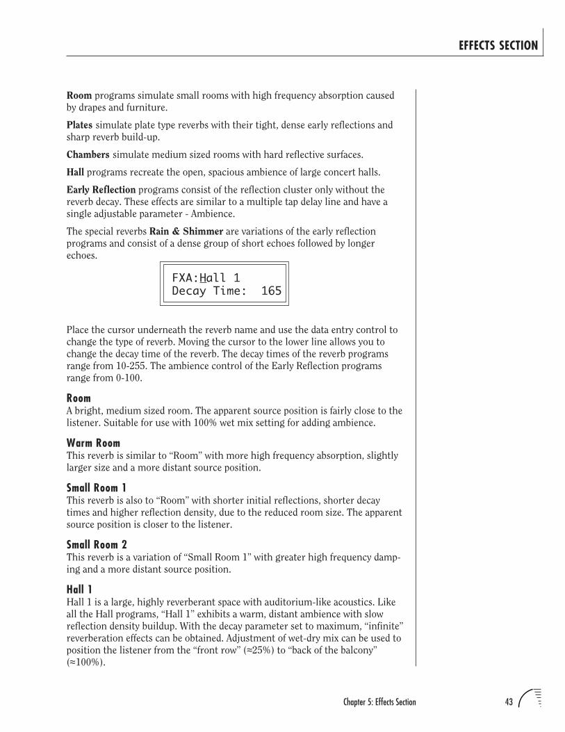
43Chapter 5: Effects Section
EFFECTS SECTION
Room programs simulate small rooms with high frequency absorption caused
by drapes and furniture.
Plates simulate plate type reverbs with their tight, dense early reflections and
sharp reverb build-up.
Chambers simulate medium sized rooms with hard reflective surfaces.
Hall programs recreate the open, spacious ambience of large concert halls.
Early Reflection programs consist of the reflection cluster only without the
reverb decay. These effects are similar to a multiple tap delay line and have a
single adjustable parameter - Ambience.
The special reverbs Rain & Shimmer are variations of the early reflection
programs and consist of a dense group of short echoes followed by longer
echoes.
FXA:Hall 1Decay Time: 165
Place the cursor underneath the reverb name and use the data entry control to
change the type of reverb. Moving the cursor to the lower line allows you to
change the decay time of the reverb. The decay times of the reverb programs
range from 10-255. The ambience control of the Early Reflection programs
range from 0-100.
RoomA bright, medium sized room. The apparent source position is fairly close to the
listener. Suitable for use with 100% wet mix setting for adding ambience.
Warm RoomThis reverb is similar to “Room” with more high frequency absorption, slightly
larger size and a more distant source position.
Small Room 1This reverb is also to “Room” with shorter initial reflections, shorter decay
times and higher reflection density, due to the reduced room size. The apparent
source position is closer to the listener.
Small Room 2This reverb is a variation of “Small Room 1” with greater high frequency damp-
ing and a more distant source position.
Hall 1Hall 1 is a large, highly reverberant space with auditorium-like acoustics. Like
all the Hall programs, “Hall 1” exhibits a warm, distant ambience with slow
reflection density buildup. With the decay parameter set to maximum, “infinite”
reverberation effects can be obtained. Adjustment of wet-dry mix can be used to
position the listener from the “front row” (≈25%) to “back of the balcony”
(≈100%).
44 UltraProteus Operation Manual
EFFECTS SECTION
Hall 2This reverb is similar to “Hall 1”, but harder and brighter, with more pro-
nounced slap echoes that come from parallel reflecting surfaces in the room.
Hall 2 also exhibits a pronounced reverb “bloom” or late-reflection buildup. A
50% wet mix creates the optimum “close” distance adjustment.
Hall 3Hall 3 is similar to “Hall 2”, but with larger scale stadium-like acoustics. Hall 3
is warmer than Hall 2 (more high frequency damping) and does not display the
obvious early reflections and slap echoes. It also exhibits a distinct predelay of
approximately 100 milliseconds and a pronounced late reflection buildup both
of which contribute to the impression of a large space. Wet mix values of 10% to
50% are most appropriate, although a setting of 100% produces an effective
cave simulation.
Chamber 1A simulation of a bright, medium-sized chamber reverb or recital hall with hard
walls. Early reflections are very prominent, with high reflection density. Moder-
ately long decays are possible at the maximum decay setting.
Chamber 2Similar to “Chamber 1” but with a much warmer sound. The wet mix adjust-
ment provides an effective control over the apparent source location from close
(10%) to very distant (100%).
Plate 1Simulates a plate reverb unit. Gives a tight, bright, slightly metallic sound.
Reflection buildup is very rapid, with high density. Early reflections are mini-
mized.
Plate 2An effect similar to Plate 1, but slightly warmer with less density.
45Chapter 5: Effects Section
EFFECTS SECTION
EARLY REFLECTION GROUPAll Early Reflection programs have a single Ambience parameter which adds
diffusion to the individual reflections. Lower ambience settings cause reflec-
tions to become more discrete, simulating harder reflecting surfaces. The early
reflection programs are simulations of increasingly large acoustic spaces, from a
small studio (Early Refl 1) to a large room like a sound stage (Early Refl 4). The
wet mix control acts effectively as source distance control. In general, lower mix
amounts are more effective as the room size increases.
Early Reflection 1
Early Reflection 2
Early Reflection 3
Early Reflection 4
Reverse Early ReflectionMore of a special effect than an acoustic simulation, Reverse ER contains a set
of exponentially increasing delay taps, creating a kind of “zip” sound at low
Ambience settings. At maximum ambience and lower wet mix values, the sound
is more authentically acoustic, with a long, delayed reflection “bloom”. The
effect is similar to a large but well damped parking garage.
SPECIAL REVERBSThese special reverbs all have a single Decay Time parameter.
RainSimilar to a repeating delay, but with complex spatial and filtering effects
occurring across the stereo panorama. The effect on percussive sounds might be
likened to a bucket of marbles raining down on a galvanized steel roof.
ShimmerDistantly related to the Rain effect, Shimmer causes input signals to be progres-
sively diffused in time and space across the stereo panorama. The spatial diffu-
sion is accompanied by a flanging effect. The program is highly responsive to
left or right-panned inputs. A stunning special effect with percussive sounds,
and especially through headphones.
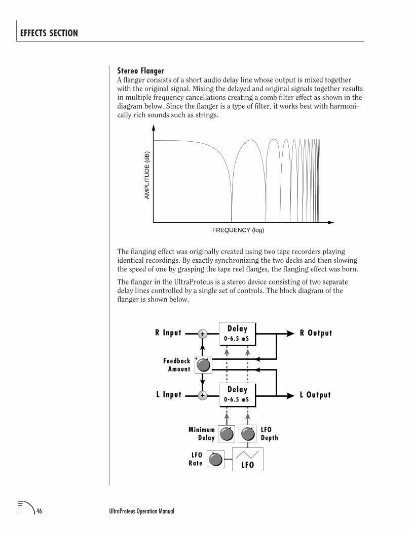
46 UltraProteus Operation Manual
EFFECTS SECTION
Stereo FlangerA flanger consists of a short audio delay line whose output is mixed together
with the original signal. Mixing the delayed and original signals together results
in multiple frequency cancellations creating a comb filter effect as shown in the
diagram below. Since the flanger is a type of filter, it works best with harmoni-
cally rich sounds such as strings.
The flanging effect was originally created using two tape recorders playing
identical recordings. By exactly synchronizing the two decks and then slowing
the speed of one by grasping the tape reel flanges, the flanging effect was born.
The flanger in the UltraProteus is a stereo device consisting of two separate
delay lines controlled by a single set of controls. The block diagram of the
flanger is shown below.
FREQUENCY (log)
AM
PLI
TU
DE
(dB
)
LFO
LFODepth
LFORate
R Output
FeedbackAmount
R Input
L Output
Min imumDelay
L Input
+ -
De lay0-6.5 mS
De lay0-6.5 mS
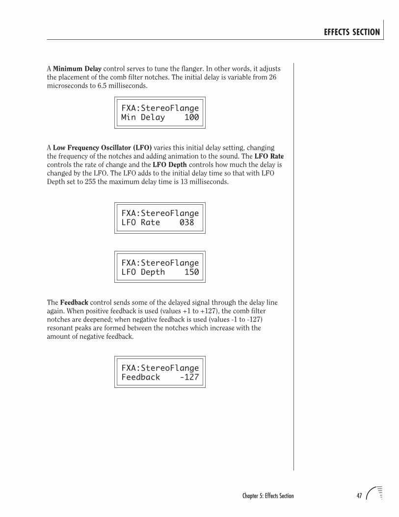
47Chapter 5: Effects Section
EFFECTS SECTION
A Minimum Delay control serves to tune the flanger. In other words, it adjusts
the placement of the comb filter notches. The initial delay is variable from 26
microseconds to 6.5 milliseconds.
FXA:StereoFlangeMin Delay 100
A Low Frequency Oscillator (LFO) varies this initial delay setting, changing
the frequency of the notches and adding animation to the sound. The LFO Rate
controls the rate of change and the LFO Depth controls how much the delay is
changed by the LFO. The LFO adds to the initial delay time so that with LFO
Depth set to 255 the maximum delay time is 13 milliseconds.
FXA:StereoFlangeLFO Rate 038
FXA:StereoFlangeLFO Depth 150
The Feedback control sends some of the delayed signal through the delay line
again. When positive feedback is used (values +1 to +127), the comb filter
notches are deepened; when negative feedback is used (values -1 to -127)
resonant peaks are formed between the notches which increase with the
amount of negative feedback.
FXA:StereoFlangeFeedback -127
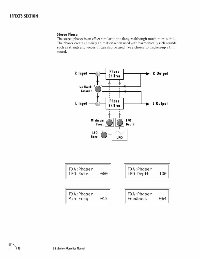
48 UltraProteus Operation Manual
FXA:PhaserLFO Rate 060
FXA:PhaserMin Freq 015
EFFECTS SECTION
Stereo PhaserThe stereo phaser is an effect similar to the flanger although much more subtle.
The phaser creates a swirly animation when used with harmonically rich sounds
such as strings and voices. It can also be used like a chorus to thicken-up a thin
sound.
LFO
LFODepth
LFORate
R Output
FeedbackAmount
R Input
L Output
Min imumFreq .
L Input
+ -
PhaseSh i f ter
PhaseSh i f ter
FXA:PhaserLFO Depth 100
FXA:PhaserFeedback 064
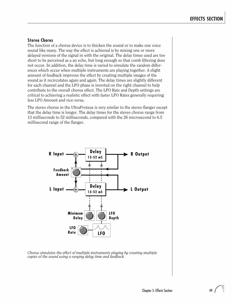
49Chapter 5: Effects Section
EFFECTS SECTION
Stereo ChorusThe function of a chorus device is to thicken the sound or to make one voice
sound like many. The way the effect is achieved is by mixing one or more
delayed versions of the signal in with the original. The delay times used are too
short to be perceived as a an echo, but long enough so that comb filtering does
not occur. In addition, the delay time is varied to simulate the random differ-
ences which occur when multiple instruments are playing together. A slight
amount of feedback improves the effect by creating multiple images of the
sound as it recirculates again and again. The delay times are slightly different
for each channel and the LFO phase is inverted on the right channel to help
contribute to the overall chorus effect. The LFO Rate and Depth settings are
critical to achieving a realistic effect with faster LFO Rates generally requiring
less LFO Amount and vice-versa.
The stereo chorus in the UltraProteus is very similar to the stereo flanger except
that the delay time is longer. The delay times for the stereo chorus range from
13 milliseconds to 52 milliseconds, compared with the 26 microsecond to 6.5
millisecond range of the flanger.
Chorus simulates the effect of multiple instruments playing by creating multiplecopies of the sound using a varying delay time and feedback.
LFO
LFODepth
LFORate
R Output
FeedbackAmount
R Input
L Output
Min imumDelay
L Input
+ -
De lay13-52 mS
De lay13-52 mS
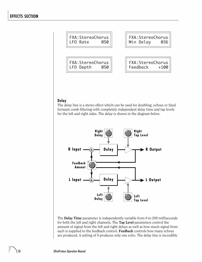
50 UltraProteus Operation Manual
FXA:StereoChorusMin Delay 036
FXA:StereoChorusFeedback +100
EFFECTS SECTION
FXA:StereoChorusLFO Rate 050
FXA:StereoChorusLFO Depth 050
The Delay Time parameter is independently variable from 0 to 209 milliseconds
for both the left and right channels. The Tap Level parameters control the
amount of signal from the left and right delays as well as how much signal from
each is supplied to the feedback control. Feedback controls how many echoes
are produced. A setting of 0 produces only one echo. The delay line is incredibly
DelayThe delay line is a stereo effect which can be used for doubling, echoes or fixed
formant comb filtering with completely independent delay time and tap levels
for the left and right sides. The delay is shown in the diagram below.
R Output
RightDe lay
FeedbackAmount
R Input De lay
RightTap Leve l
L Output
Lef tDe lay
L Input
Lef tTap Leve l
+ -
De lay
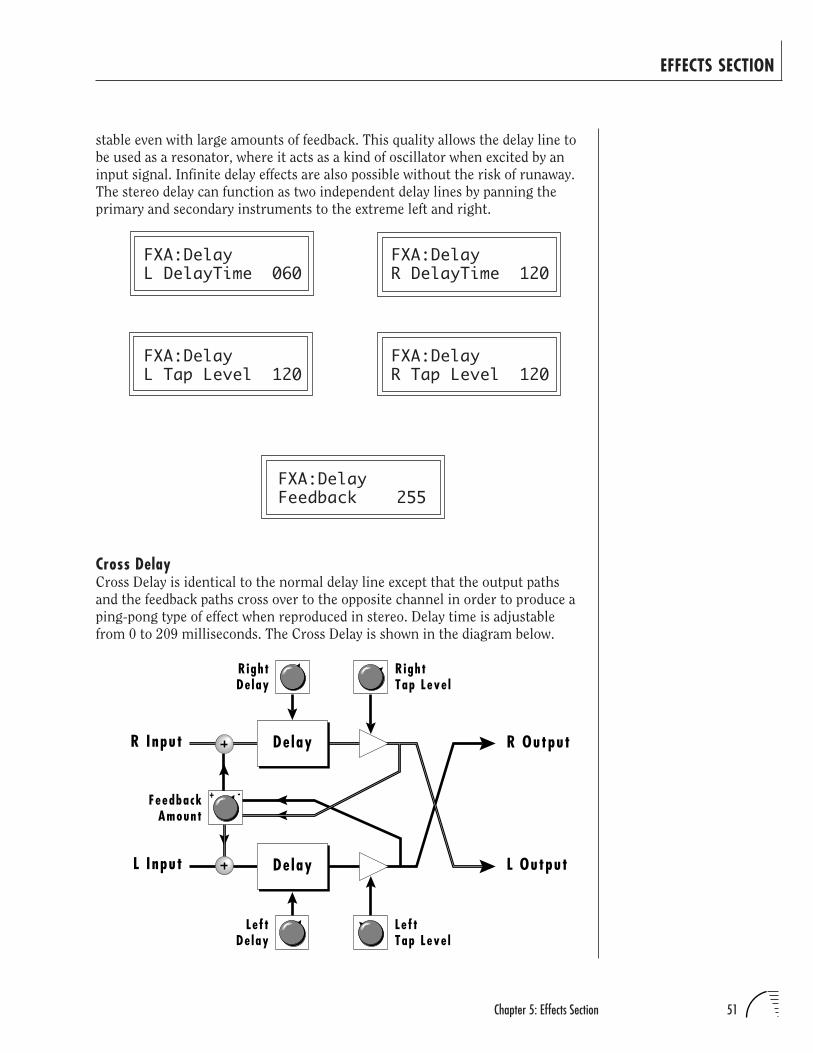
51Chapter 5: Effects Section
stable even with large amounts of feedback. This quality allows the delay line to
be used as a resonator, where it acts as a kind of oscillator when excited by an
input signal. Infinite delay effects are also possible without the risk of runaway.
The stereo delay can function as two independent delay lines by panning the
primary and secondary instruments to the extreme left and right.
FXA:DelayL DelayTime 060
FXA:DelayL Tap Level 120
EFFECTS SECTION
FXA:DelayFeedback 255
Cross DelayCross Delay is identical to the normal delay line except that the output paths
and the feedback paths cross over to the opposite channel in order to produce a
ping-pong type of effect when reproduced in stereo. Delay time is adjustable
from 0 to 209 milliseconds. The Cross Delay is shown in the diagram below.
FXA:DelayR DelayTime 120
FXA:DelayR Tap Level 120
R Output
RightDe lay
FeedbackAmount
R Input De lay
RightTap Leve l
L Output
Lef tDe lay
L Input
Lef tTap Leve l
+ -
De lay
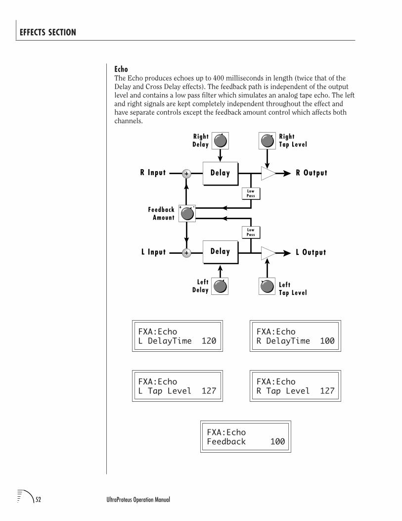
52 UltraProteus Operation Manual
EchoThe Echo produces echoes up to 400 milliseconds in length (twice that of the
Delay and Cross Delay effects). The feedback path is independent of the output
level and contains a low pass filter which simulates an analog tape echo. The left
and right signals are kept completely independent throughout the effect and
have separate controls except the feedback amount control which affects both
channels.
EFFECTS SECTION
FXA:EchoL DelayTime 120
FXA:EchoL Tap Level 127
FXA:EchoR DelayTime 100
FXA:EchoR Tap Level 127
FXA:EchoFeedback 100
R Output
RightDe lay
FeedbackAmount
R Input De lay
RightTap Leve l
L Output
Lef tDe lay
L Input
Lef tTap Leve l
+ -
De lay
LowPass
LowPass
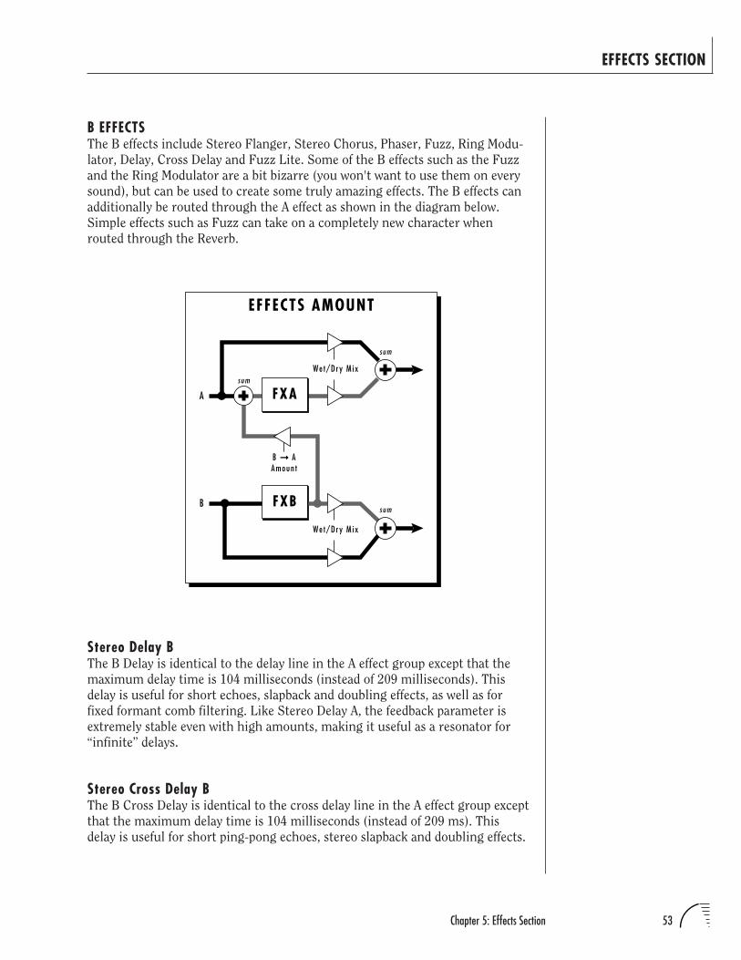
53Chapter 5: Effects Section
B EFFECTSThe B effects include Stereo Flanger, Stereo Chorus, Phaser, Fuzz, Ring Modu-
lator, Delay, Cross Delay and Fuzz Lite. Some of the B effects such as the Fuzz
and the Ring Modulator are a bit bizarre (you won't want to use them on every
sound), but can be used to create some truly amazing effects. The B effects can
additionally be routed through the A effect as shown in the diagram below.
Simple effects such as Fuzz can take on a completely new character when
routed through the Reverb.
EFFECTS SECTION
Stereo Delay BThe B Delay is identical to the delay line in the A effect group except that the
maximum delay time is 104 milliseconds (instead of 209 milliseconds). This
delay is useful for short echoes, slapback and doubling effects, as well as for
fixed formant comb filtering. Like Stereo Delay A, the feedback parameter is
extremely stable even with high amounts, making it useful as a resonator for
“infinite” delays.
Stereo Cross Delay BThe B Cross Delay is identical to the cross delay line in the A effect group except
that the maximum delay time is 104 milliseconds (instead of 209 ms). This
delay is useful for short ping-pong echoes, stereo slapback and doubling effects.
FXA
FXB
EFFECTS AMOUNT
Wet/Dry M ix
We t/Dry M ix
sum
sum
sum
B AAmoun t
A
B
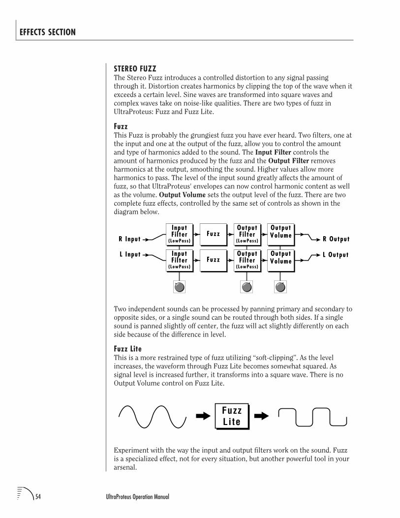
54 UltraProteus Operation Manual
STEREO FUZZThe Stereo Fuzz introduces a controlled distortion to any signal passing
through it. Distortion creates harmonics by clipping the top of the wave when it
exceeds a certain level. Sine waves are transformed into square waves and
complex waves take on noise-like qualities. There are two types of fuzz in
UltraProteus: Fuzz and Fuzz Lite.
FuzzThis Fuzz is probably the grungiest fuzz you have ever heard. Two filters, one at
the input and one at the output of the fuzz, allow you to control the amount
and type of harmonics added to the sound. The Input Filter controls the
amount of harmonics produced by the fuzz and the Output Filter removes
harmonics at the output, smoothing the sound. Higher values allow more
harmonics to pass. The level of the input sound greatly affects the amount of
fuzz, so that UltraProteus' envelopes can now control harmonic content as well
as the volume. Output Volume sets the output level of the fuzz. There are two
complete fuzz effects, controlled by the same set of controls as shown in the
diagram below.
EFFECTS SECTION
R OutputR Input
L Input L OutputInputF i l te r Fuzz
OutputF i l te r
(LowPass) (LowPass)
InputF i l te r Fuzz
OutputF i l te r
(LowPass) (LowPass)
OutputVo lume
OutputVo lume
Two independent sounds can be processed by panning primary and secondary to
opposite sides, or a single sound can be routed through both sides. If a single
sound is panned slightly off center, the fuzz will act slightly differently on each
side because of the difference in level.
Fuzz LiteThis is a more restrained type of fuzz utilizing “soft-clipping”. As the level
increases, the waveform through Fuzz Lite becomes somewhat squared. As
signal level is increased further, it transforms into a square wave. There is no
Output Volume control on Fuzz Lite.
Experiment with the way the input and output filters work on the sound. Fuzz
is a specialized effect, not for every situation, but another powerful tool in your
arsenal.
FuzzLi te
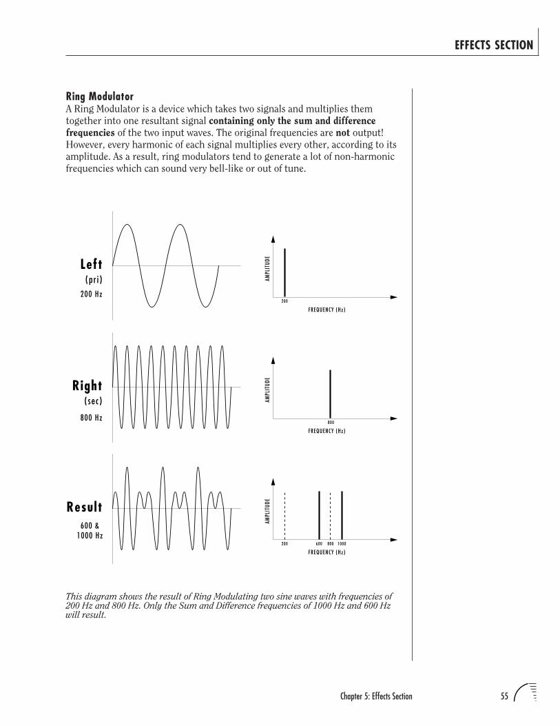
55Chapter 5: Effects Section
EFFECTS SECTION
Ring ModulatorA Ring Modulator is a device which takes two signals and multiplies them
together into one resultant signal containing only the sum and difference
frequencies of the two input waves. The original frequencies are not output!
However, every harmonic of each signal multiplies every other, according to its
amplitude. As a result, ring modulators tend to generate a lot of non-harmonic
frequencies which can sound very bell-like or out of tune.
FREQUENCY (Hz)
AMPL
ITUD
E
200
FREQUENCY (Hz)
AMPL
ITUD
E
800
FREQUENCY (Hz)
AMPL
ITUD
E
200 600 800 1000
Left
Right
Result
200 Hz
800 Hz
600 &1000 Hz
(pr i )
(sec)
This diagram shows the result of Ring Modulating two sine waves with frequencies of200 Hz and 800 Hz. Only the Sum and Difference frequencies of 1000 Hz and 600 Hzwill result.
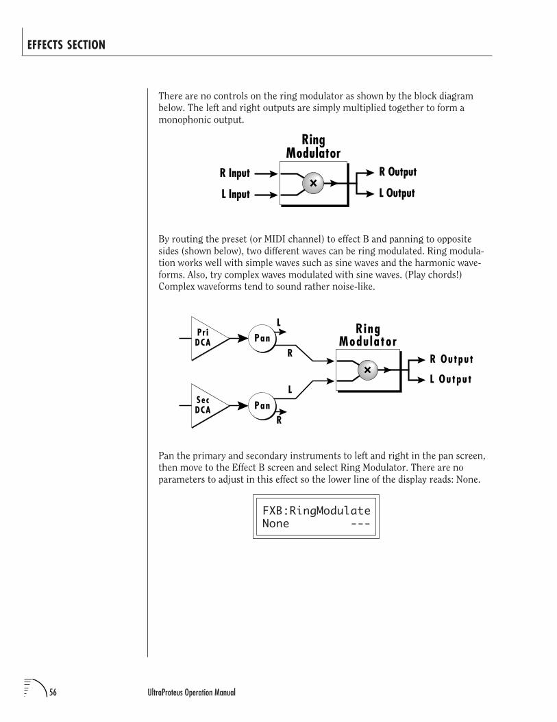
56 UltraProteus Operation Manual
EFFECTS SECTION
There are no controls on the ring modulator as shown by the block diagram
below. The left and right outputs are simply multiplied together to form a
monophonic output.
By routing the preset (or MIDI channel) to effect B and panning to opposite
sides (shown below), two different waves can be ring modulated. Ring modula-
tion works well with simple waves such as sine waves and the harmonic wave-
forms. Also, try complex waves modulated with sine waves. (Play chords!)
Complex waveforms tend to sound rather noise-like.
R
L
R Output
L Output
R ingModu latorPan
R
Pr iDCA
PanL
SecDCA
Pan the primary and secondary instruments to left and right in the pan screen,
then move to the Effect B screen and select Ring Modulator. There are no
parameters to adjust in this effect so the lower line of the display reads: None.
FXB:RingModulateNone ---
R Output
L Output
RingModulator
R Input
L Input

57Chapter 6: Hyperpreset Menu
UltraProteus HYPERPRESET MENU

58 UltraProteus Operation Manual
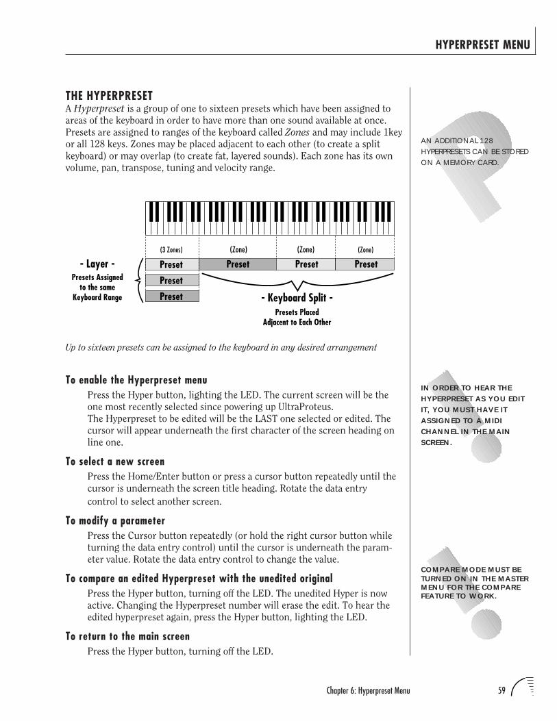
59Chapter 6: Hyperpreset Menu
HYPERPRESET MENU
THE HYPERPRESETA Hyperpreset is a group of one to sixteen presets which have been assigned to
areas of the keyboard in order to have more than one sound available at once.
Presets are assigned to ranges of the keyboard called Zones and may include 1key
or all 128 keys. Zones may be placed adjacent to each other (to create a split
keyboard) or may overlap (to create fat, layered sounds). Each zone has its own
volume, pan, transpose, tuning and velocity range.
AN ADDITIONAL 128HYPERPRESETS CAN BE STOREDON A MEMORY CARD.
IN ORDER TO HEAR THEHYPERPRESET AS YOU EDITIT, YOU MUST HAVE ITASSIGNED TO A MIDICHANNEL IN THE MAINSCREEN.
Up to sixteen presets can be assigned to the keyboard in any desired arrangement
Preset Preset
Preset
Preset
Preset Preset- Layer -
- Keyboard Split -
(3 Zones) (Zone) (Zone) (Zone)
Presets PlacedAdjacent to Each Other
Presets Assignedto the same
Keyboard Range
COMPARE MODE MUST BETURNED ON IN THE MASTERMENU FOR THE COMPAREFEATURE TO WORK.
To enable the Hyperpreset menuPress the Hyper button, lighting the LED. The current screen will be the
one most recently selected since powering up UltraProteus.
The Hyperpreset to be edited will be the LAST one selected or edited. The
cursor will appear underneath the first character of the screen heading on
line one.
To select a new screenPress the Home/Enter button or press a cursor button repeatedly until the
cursor is underneath the screen title heading. Rotate the data entry
control to select another screen.
To modify a parameterPress the Cursor button repeatedly (or hold the right cursor button while
turning the data entry control) until the cursor is underneath the param-
eter value. Rotate the data entry control to change the value.
To compare an edited Hyperpreset with the unedited originalPress the Hyper button, turning off the LED. The unedited Hyper is now
active. Changing the Hyperpreset number will erase the edit. To hear the
edited hyperpreset again, press the Hyper button, lighting the LED.
To return to the main screenPress the Hyper button, turning off the LED.
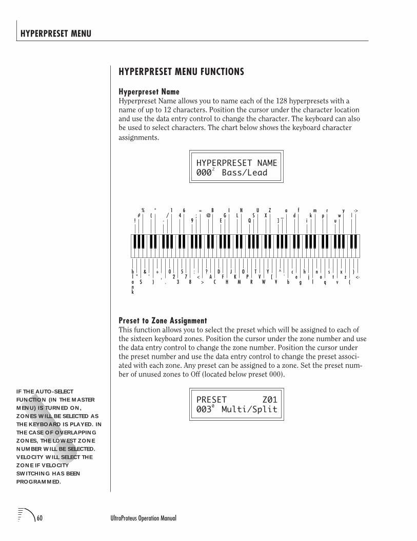
60 UltraProteus Operation Manual
Preset to Zone AssignmentThis function allows you to select the preset which will be assigned to each of
the sixteen keyboard zones. Position the cursor under the zone number and use
the data entry control to change the zone number. Position the cursor under
the preset number and use the data entry control to change the preset associ-
ated with each zone. Any preset can be assigned to a zone. Set the preset num-
ber of unused zones to Off (located below preset 000).
PRESET Z01003 Multi/Split
HYPERPRESET MENU
HYPERPRESET MENU FUNCTIONS
Hyperpreset NameHyperpreset Name allows you to name each of the 128 hyperpresets with a
name of up to 12 characters. Position the cursor under the character location
and use the data entry control to change the character. The keyboard can also
be used to select characters. The chart below shows the keyboard character
assignments.
HYPERPRESET NAME000 Bass/Lead
IF THE AUTO-SELECTFUNCTION (IN THE MASTERMENU) IS TURNED ON,ZONES WILL BE SELECTED ASTHE KEYBOARD IS PLAYED. INTHE CASE OF OVERLAPPINGZONES, THE LOWEST ZONENUMBER WILL BE SELECTED.VELOCITY WILL SELECT THEZONE IF VELOCITYSWITCHING HAS BEENPROGRAMMED.
2
02
3
57
8
:<
>
?A
C
DF
H
JK
M
OP
R
TV
W
Y[
¥
^`
b
ce
g
hj
l
no
q
st
v
xz
<-
+,
.
&'
)
blank
"$
46
9;
=@
B
EG
IL
N
QS
UX
Z
]_
ad
f
ik
mp
r
uw
y|
->
-/
1(
*
!#
%
0
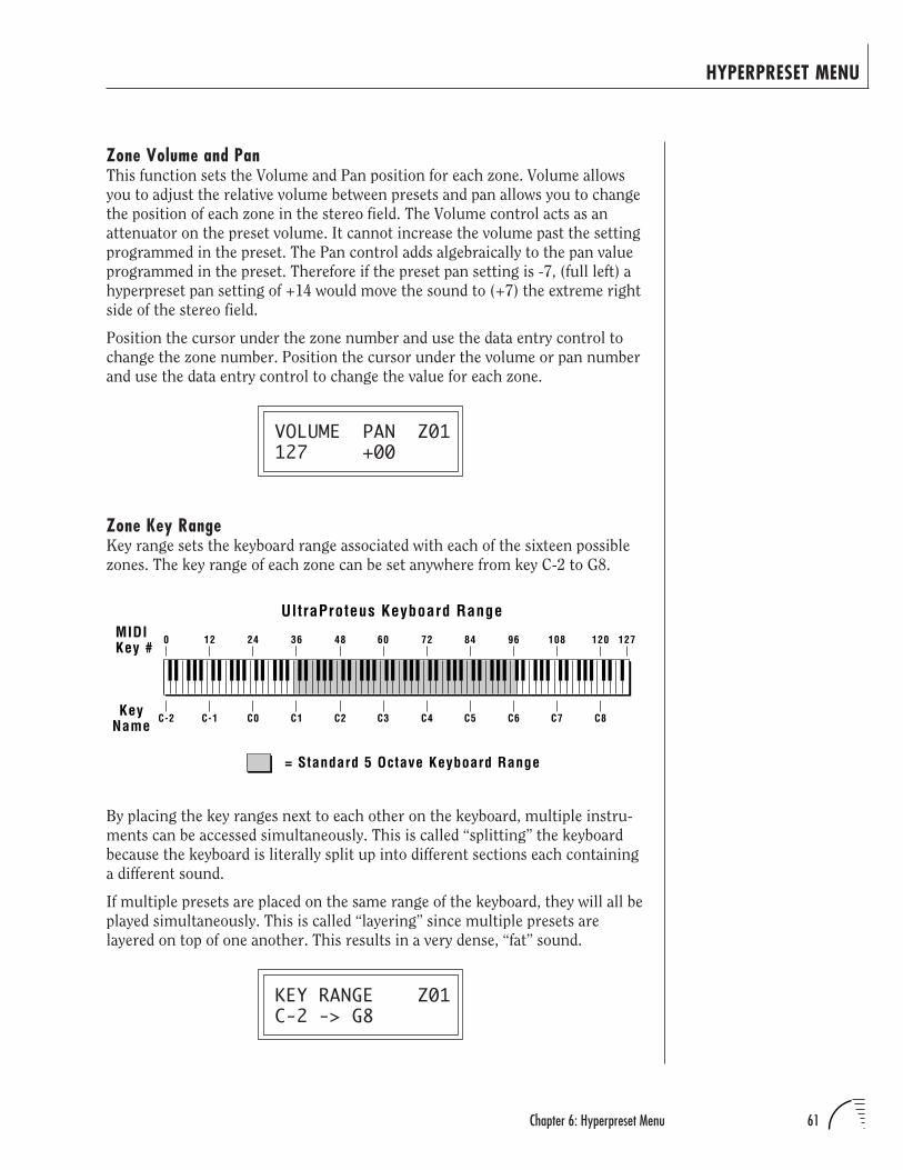
61Chapter 6: Hyperpreset Menu
Zone Volume and PanThis function sets the Volume and Pan position for each zone. Volume allows
you to adjust the relative volume between presets and pan allows you to change
the position of each zone in the stereo field. The Volume control acts as an
attenuator on the preset volume. It cannot increase the volume past the setting
programmed in the preset. The Pan control adds algebraically to the pan value
programmed in the preset. Therefore if the preset pan setting is -7, (full left) a
hyperpreset pan setting of +14 would move the sound to (+7) the extreme right
side of the stereo field.
Position the cursor under the zone number and use the data entry control to
change the zone number. Position the cursor under the volume or pan number
and use the data entry control to change the value for each zone.
VOLUME PAN Z01127 +00
Zone Key RangeKey range sets the keyboard range associated with each of the sixteen possible
zones. The key range of each zone can be set anywhere from key C-2 to G8.
HYPERPRESET MENU
C-2 C-1 C0 C1 C2 C3 C4 C5 C6 C7 C8
= Standard 5 Octave Keyboard Range
UltraProteus Keyboard RangeMIDIKey #
KeyName
0 12 24 36 48 60 72 84 96 108 120 127
By placing the key ranges next to each other on the keyboard, multiple instru-
ments can be accessed simultaneously. This is called “splitting” the keyboard
because the keyboard is literally split up into different sections each containing
a different sound.
If multiple presets are placed on the same range of the keyboard, they will all be
played simultaneously. This is called “layering” since multiple presets are
layered on top of one another. This results in a very dense, “fat” sound.
KEY RANGE Z01C-2 -> G8
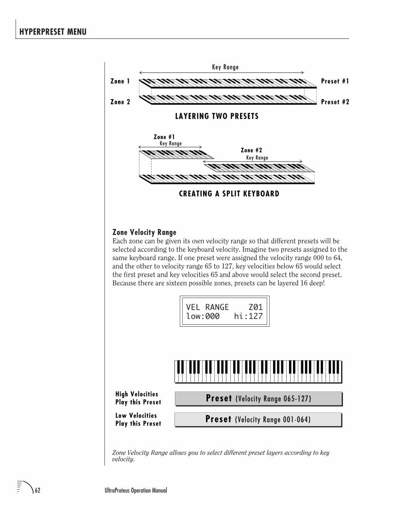
62 UltraProteus Operation Manual
Zone Velocity Range allows you to select different preset layers according to keyvelocity.
HYPERPRESET MENU
Preset #1
Preset #2
LAYERING TWO PRESETS
Key Range
Zone 1
Zone 2
Zone #1
Zone #2Key Range
Key Range
CREATING A SPLIT KEYBOARD
Zone Velocity RangeEach zone can be given its own velocity range so that different presets will be
selected according to the keyboard velocity. Imagine two presets assigned to the
same keyboard range. If one preset were assigned the velocity range 000 to 64,
and the other to velocity range 65 to 127, key velocities below 65 would select
the first preset and key velocities 65 and above would select the second preset.
Because there are sixteen possible zones, presets can be layered 16 deep!
VEL RANGE Z01low:000 hi:127
Preset (Ve loc i ty Range 001-064)Low Velocit ies Play this Preset
Preset (Ve loc i ty Range 065-127)High Velocit ies Play this Preset
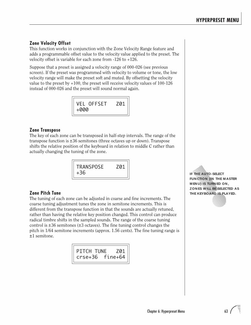
63Chapter 6: Hyperpreset Menu
Zone Velocity OffsetThis function works in conjunction with the Zone Velocity Range feature and
adds a programmable offset value to the velocity value applied to the preset. The
velocity offset is variable for each zone from -126 to +126.
Suppose that a preset is assigned a velocity range of 000-026 (see previous
screen). If the preset was programmed with velocity to volume or tone, the low
velocity range will make the preset soft and muted. By offsetting the velocity
value to the preset by +100, the preset will receive velocity values of 100-126
instead of 000-026 and the preset will sound normal again.
VEL OFFSET Z01+000
Zone TransposeThe key of each zone can be transposed in half-step intervals. The range of the
transpose function is ±36 semitones (three octaves up or down). Transpose
shifts the relative position of the keyboard in relation to middle C rather than
actually changing the tuning of the zone.
TRANSPOSE Z01+36
Zone Pitch TuneThe tuning of each zone can be adjusted in coarse and fine increments. The
coarse tuning adjustment tunes the zone in semitone increments. This is
different from the transpose function in that the sounds are actually retuned,
rather than having the relative key position changed. This control can produce
radical timbre shifts in the sampled sounds. The range of the coarse tuning
control is ±36 semitones (±3 octaves). The fine tuning control changes the
pitch in 1/64 semitone increments (approx. 1.56 cents). The fine tuning range is
±1 semitone.
PITCH TUNE Z01crse+36 fine+64
HYPERPRESET MENU
IF THE AUTO-SELECTFUNCTION (IN THE MASTERMENU) IS TURNED ON,ZONES WILL BE SELECTED ASTHE KEYBOARD IS PLAYED.
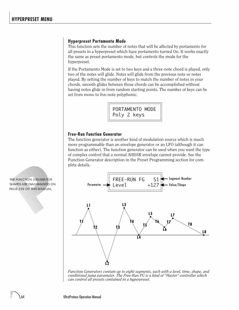
64 UltraProteus Operation Manual
HYPERPRESET MENU
THE FUNCTION GENERATORSHAPES ARE DIAGRAMMED ONPAGE 239 OF THIS MANUAL.
Hyperpreset Portamento ModeThis function sets the number of notes that will be affected by portamento for
all presets in a hyperpreset which have portamento turned On. It works exactly
the same as preset portamento mode, but controls the mode for the
hyperpreset.
If the Portamento Mode is set to two keys and a three-note chord is played, only
two of the notes will glide. Notes will glide from the previous note or notes
played. By setting the number of keys to match the number of notes in your
chords, smooth glides between those chords can be accomplished without
having notes glide in from random starting points. The number of keys can be
set from mono to five-note polyphonic.
PORTAMENTO MODEPoly 2 keys
Free-Run Function GeneratorThe function generator is another kind of modulation source which is much
more programmable than an envelope generator or an LFO (although it can
function as either). The function generator can be used when you want the type
of complex control that a normal AHDSR envelope cannot provide. See the
Function Generator description in the Preset Programming section for com-
plete details.
FREE-RUN FG S1Level +127
Function Generators contain up to eight segments, each with a level, time, shape, andconditional jump parameter. The Free-Run FG is a kind of “Master” controller whichcan control all presets contained in a hyperpreset.
L1
T1
L2
L3
L4
L5
L6
L7
L8T2 T3
T4T5
T6 T7 T8
Segment Number
Parameter Value/Shape
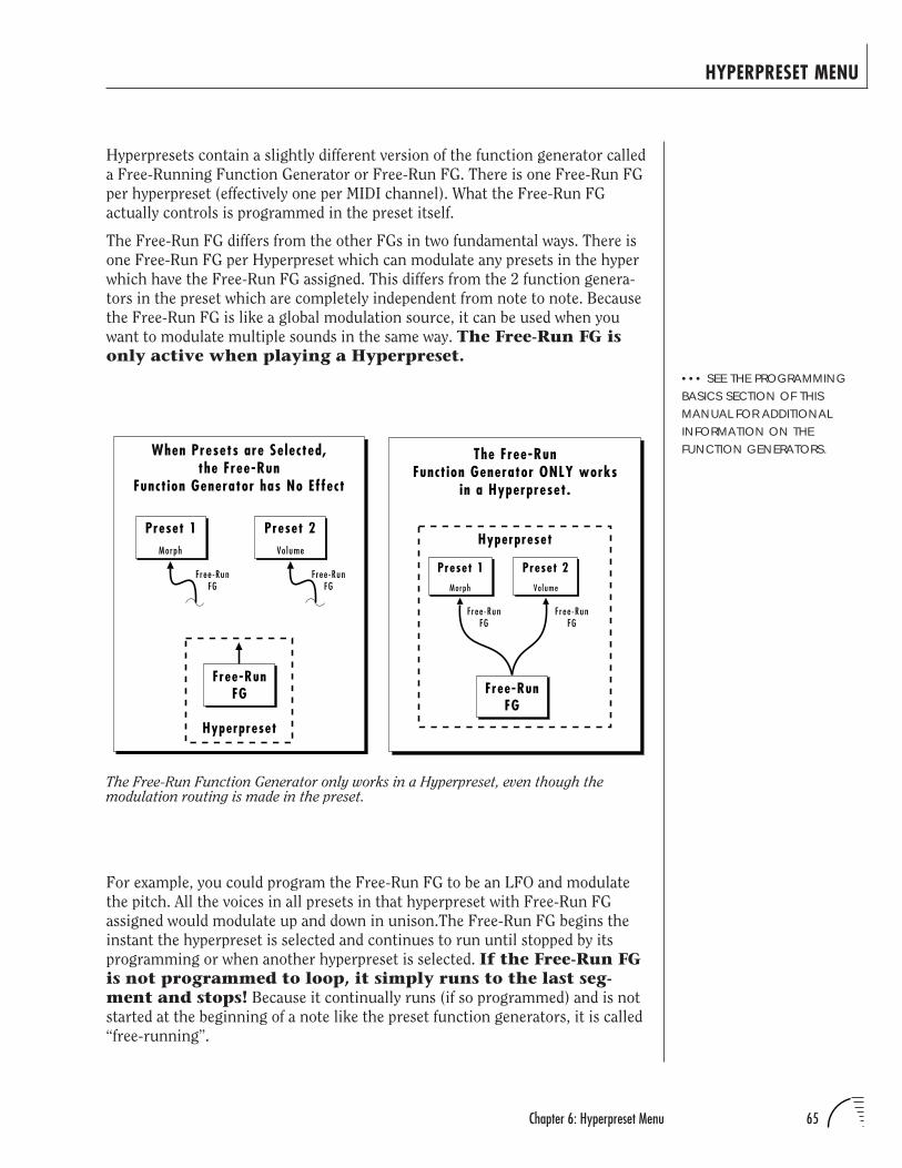
65Chapter 6: Hyperpreset Menu
HYPERPRESET MENU
Hyperpresets contain a slightly different version of the function generator called
a Free-Running Function Generator or Free-Run FG. There is one Free-Run FG
per hyperpreset (effectively one per MIDI channel). What the Free-Run FG
actually controls is programmed in the preset itself.
The Free-Run FG differs from the other FGs in two fundamental ways. There is
one Free-Run FG per Hyperpreset which can modulate any presets in the hyper
which have the Free-Run FG assigned. This differs from the 2 function genera-
tors in the preset which are completely independent from note to note. Because
the Free-Run FG is like a global modulation source, it can be used when you
want to modulate multiple sounds in the same way. The Free-Run FG isonly active when playing a Hyperpreset.
••• SEE THE PROGRAMMINGBASICS SECTION OF THISMANUAL FOR ADDITIONALINFORMATION ON THEFUNCTION GENERATORS.
For example, you could program the Free-Run FG to be an LFO and modulate
the pitch. All the voices in all presets in that hyperpreset with Free-Run FG
assigned would modulate up and down in unison.The Free-Run FG begins the
instant the hyperpreset is selected and continues to run until stopped by its
programming or when another hyperpreset is selected. If the Free-Run FGis not programmed to loop, it simply runs to the last seg-ment and stops! Because it continually runs (if so programmed) and is not
started at the beginning of a note like the preset function generators, it is called
“free-running”.
Morph
Preset 1Volume
Preset 2
The Free-RunFunction Generator ONLY works
in a Hyperpreset.
Free-RunFG
Hyperpreset
Free-RunFG
Free-RunFG
Morph
Preset 1Volume
Preset 2
When Presets are Selected,the Free-Run
Function Generator has No Effect
Free-RunFG
Hyperpreset
Free-RunFG
Free-RunFG
The Free-Run Function Generator only works in a Hyperpreset, even though themodulation routing is made in the preset.
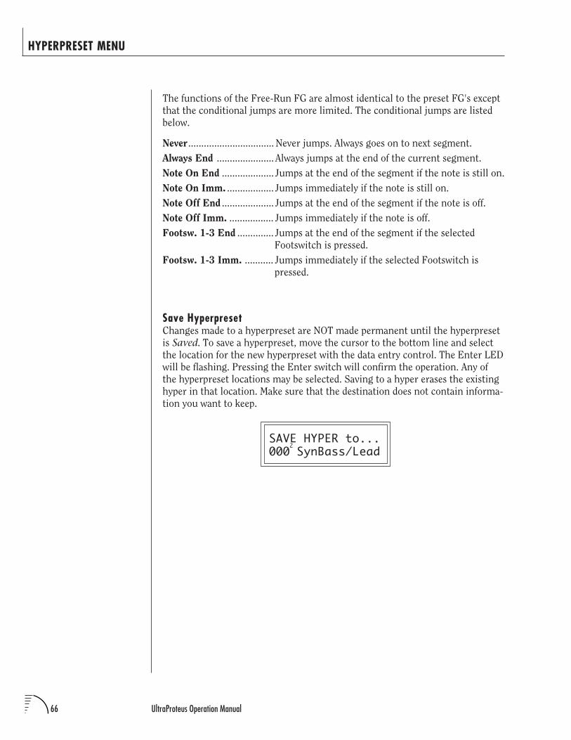
66 UltraProteus Operation Manual
HYPERPRESET MENU
The functions of the Free-Run FG are almost identical to the preset FG's except
that the conditional jumps are more limited. The conditional jumps are listed
below.
Never ................................. Never jumps. Always goes on to next segment.
Always End ...................... Always jumps at the end of the current segment.
Note On End .................... Jumps at the end of the segment if the note is still on.
Note On Imm. .................. Jumps immediately if the note is still on.
Note Off End .................... Jumps at the end of the segment if the note is off.
Note Off Imm. ................. Jumps immediately if the note is off.
Footsw. 1-3 End .............. Jumps at the end of the segment if the selected
Footswitch is pressed.
Footsw. 1-3 Imm. ........... Jumps immediately if the selected Footswitch is
pressed.
Save HyperpresetChanges made to a hyperpreset are NOT made permanent until the hyperpreset
is Saved. To save a hyperpreset, move the cursor to the bottom line and select
the location for the new hyperpreset with the data entry control. The Enter LED
will be flashing. Pressing the Enter switch will confirm the operation. Any of
the hyperpreset locations may be selected. Saving to a hyper erases the existing
hyper in that location. Make sure that the destination does not contain informa-
tion you want to keep.
SAVE HYPER to...000 SynBass/Lead2

67Chapter 7: Preset Programming
PRESET PROGRAMMING
UltraProteus PRESET PROGRAMMING

68 UltraProteus Operation Manual
PRESET PROGRAMMING
69Chapter 7: Preset Programming
PRESET PROGRAMMING
This chapter explains how preset sounds are constructed in UltraProteus. It also
contains important background information on the various programming
aspects of the instrument.
If you are new to synthesizers and electronic music, you may need more
background information than this manual provides. There are many books
dedicated to synthesizer basics and MIDI available through your local music
dealer. Magazines such as Keyboard and Electronic Musician, which are
available at most newstands, contain current information on the subject, as
well as valuable programming tips.
Your initial involvement with UltraProteus will most likely consist of using the
existing presets and selecting MIDI channels. While the factory presets are very
good, there are probably some things you would like to change, perhaps the
LFO speed, the filter brightness, or the attack time. You may also want to make
your own custom presets using complex modulation routings. There are 128
user locations (000°-127°) available to store your own creations or edited
factory presets.
Editing PresetsIt’s easy to create new presets by using the Preset Edit menu to modify existing
presets. This is really the best way of getting aquainted with UltraProteus. If you
don't like the results, simply change the preset momentarily and you'll be back
to the original sound. Changes are not made permanent until you SAVE a
preset. Therefore, you can experiment all you want with Presets, Hyperpresets
or Midimaps without worrying about losing a sound.
The Copy menu is another way to edit presets. Elements of a preset can be
quickly copied to another to create a new hybrid preset.
We encourage you to actually try out the different functions as you read about
them. Hearing what a control actually does will remove a lot of the mystery
associated with it. The chapter entitled “Step-By-Step” walks you through many
of the basic programming functions. Read this chapter first, however, since it
contains important information that you need to know.
UltraProteus has an extensive modulation implementation using two multi-
wave LFO’s (Low Frequency Oscillators), three envelope generators, two multi-
segment function generators and the ability to respond to multiple MIDI
controllers. You can simultaneously route any combination of these control
sources to multiple destinations.
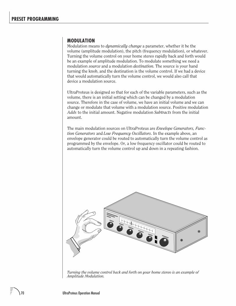
70 UltraProteus Operation Manual
PRESET PROGRAMMING
MODULATIONModulation means to dynamically change a parameter, whether it be the
volume (amplitude modulation), the pitch (frequency modulation), or whatever.
Turning the volume control on your home stereo rapidly back and forth would
be an example of amplitude modulation. To modulate something we need a
modulation source and a modulation destination. The source is your hand
turning the knob, and the destination is the volume control. If we had a device
that would automatically turn the volume control, we would also call that
device a modulation source.
UltraProteus is designed so that for each of the variable parameters, such as the
volume, there is an initial setting which can be changed by a modulation
source. Therefore in the case of volume, we have an initial volume and we can
change or modulate that volume with a modulation source. Positive modulation
Adds to the initial amount. Negative modulation Subtracts from the initial
amount.
The main modulation sources on UltraProteus are Envelope Generators, Func-
tion Generators and Low Frequency Oscillators. In the example above, an
envelope generator could be routed to automatically turn the volume control as
programmed by the envelope. Or, a low frequency oscillator could be routed to
automatically turn the volume control up and down in a repeating fashion.
Turning the volume control back and forth on your home stereo is an example ofAmplitude Modulation.
71Chapter 7: Preset Programming
PRESET PROGRAMMING
MODULATION SOURCESUltraProteus uses three kinds of modulation sources.
NOTE-ON MODULATION CONTROLValues which are generated at the start of a note and do not change during the
note.
Keyboard KeyWhich key is pressed.
Key VelocityHow fast the key is pressed.
Pitch Wheel, Control A-B-C-D, Mono Pressure, Free-Run Func. GeneratorThese are variable controls which are measured only once at
Note-On time.
REALTIME MODULATION CONTROLValues which can be continuously changed during the entire duration of the
sound.
Pitch WheelA synthesizer pitch bend wheel.
Miscellaneous Controllers (A-B-C-D)Any type of MIDI continuous controller data.
Keyboard Pressure (mono aftertouch)Key Pressure applied after the key is initially pressed.
Polyphonic Key PressureKey Pressure from a controller capable of generating polyphonic pressure
data.
Low Frequency Oscillators (2 per preset)Generate repeating waves.
Envelope Generators (3 per preset)Generate a programmable “contour” which changes over time when a key
is pressed.
Function Generators (2 per preset)Generate complex programmable shapes which begin when a key is
pressed.
Free-Running Function Generators (1 per hyperpreset)Generate complex programmable shapes which begin whenever a
hyperpreset is selected.
SEE THE END OF THIS CHAPTERFOR MORE INFORMATION ONMIDI CONTROLLERS A-B-C-D.
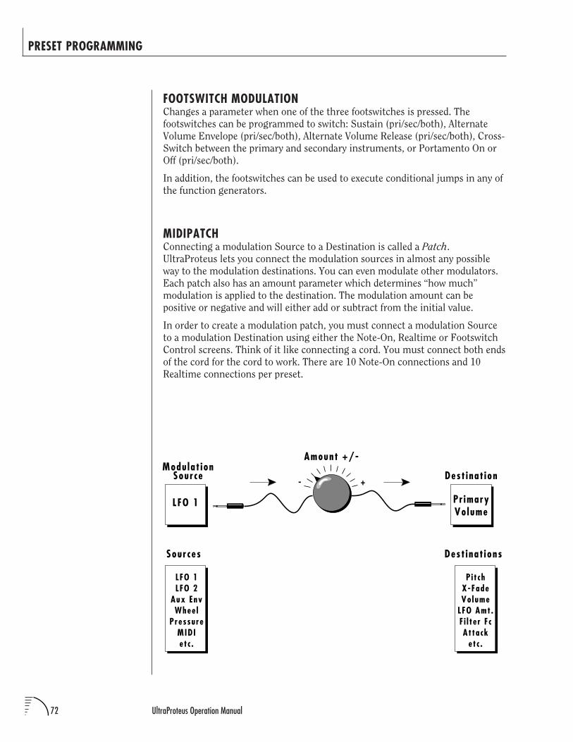
72 UltraProteus Operation Manual
PRESET PROGRAMMING
FOOTSWITCH MODULATIONChanges a parameter when one of the three footswitches is pressed. The
footswitches can be programmed to switch: Sustain (pri/sec/both), Alternate
Volume Envelope (pri/sec/both), Alternate Volume Release (pri/sec/both), Cross-
Switch between the primary and secondary instruments, or Portamento On or
Off (pri/sec/both).
In addition, the footswitches can be used to execute conditional jumps in any of
the function generators.
MIDIPATCHConnecting a modulation Source to a Destination is called a Patch.
UltraProteus lets you connect the modulation sources in almost any possible
way to the modulation destinations. You can even modulate other modulators.
Each patch also has an amount parameter which determines “how much”
modulation is applied to the destination. The modulation amount can be
positive or negative and will either add or subtract from the initial value.
In order to create a modulation patch, you must connect a modulation Source
to a modulation Destination using either the Note-On, Realtime or Footswitch
Control screens. Think of it like connecting a cord. You must connect both ends
of the cord for the cord to work. There are 10 Note-On connections and 10
Realtime connections per preset.
Sources
LFO 1LFO 2
Aux EnvWhee l
PressureMIDIet c .
Dest inat ions
Pi t chX-FadeVolume
LFO Amt.F i l te r F cAttack
etc .
Modu lat ionSource Dest inat ion
Amount +/-
LFO 1 Pr imaryVolume
+-
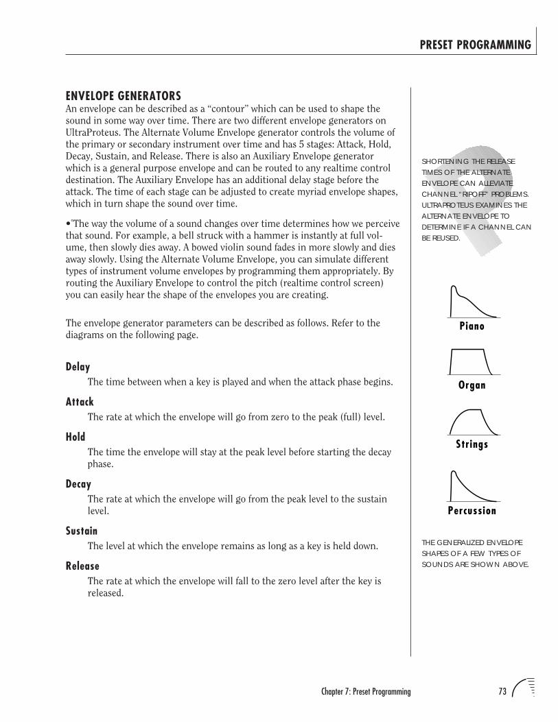
73Chapter 7: Preset Programming
PRESET PROGRAMMING
ENVELOPE GENERATORSAn envelope can be described as a “contour” which can be used to shape the
sound in some way over time. There are two different envelope generators on
UltraProteus. The Alternate Volume Envelope generator controls the volume of
the primary or secondary instrument over time and has 5 stages: Attack, Hold,
Decay, Sustain, and Release. There is also an Auxiliary Envelope generator
which is a general purpose envelope and can be routed to any realtime control
destination. The Auxiliary Envelope has an additional delay stage before the
attack. The time of each stage can be adjusted to create myriad envelope shapes,
which in turn shape the sound over time.
• The way the volume of a sound changes over time determines how we perceive
that sound. For example, a bell struck with a hammer is instantly at full vol-
ume, then slowly dies away. A bowed violin sound fades in more slowly and dies
away slowly. Using the Alternate Volume Envelope, you can simulate different
types of instrument volume envelopes by programming them appropriately. By
routing the Auxiliary Envelope to control the pitch (realtime control screen)
you can easily hear the shape of the envelopes you are creating.
The envelope generator parameters can be described as follows. Refer to the
diagrams on the following page.
DelayThe time between when a key is played and when the attack phase begins.
AttackThe rate at which the envelope will go from zero to the peak (full) level.
HoldThe time the envelope will stay at the peak level before starting the decay
phase.
DecayThe rate at which the envelope will go from the peak level to the sustain
level.
SustainThe level at which the envelope remains as long as a key is held down.
ReleaseThe rate at which the envelope will fall to the zero level after the key is
released.
SHORTENING THE RELEASETIMES OF THE ALTERNATEENVELOPE CAN ALLEVIATECHANNEL “RIPOFF” PROBLEMS.ULTRAPROTEUS EXAMINES THEALTERNATE ENVELOPE TODETERMINE IF A CHANNEL CANBE REUSED.
THE GENERALIZED ENVELOPESHAPES OF A FEW TYPES OFSOUNDS ARE SHOWN ABOVE.
Percussion
Piano
Organ
Strings
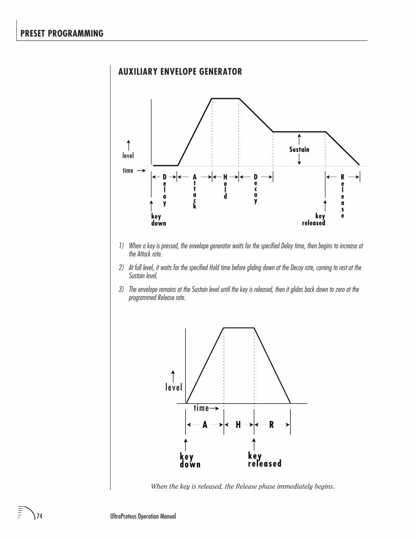
74 UltraProteus Operation Manual
PRESET PROGRAMMING
Delay
level
time
keydown
Attack
Hold
Decay
Sustain
Releasekey
released
AUXILIARY ENVELOPE GENERATOR
When the key is released, the Release phase immediately begins.
1) When a key is pressed, the envelope generator waits for the specified Delay time, then begins to increase atthe Attack rate.
2) At full level, it waits for the specified Hold time before gliding down at the Decay rate, coming to rest at theSustain level.
3) The envelope remains at the Sustain level until the key is released, then it glides back down to zero at theprogrammed Release rate.
l e ve l
keydown
keyre leased
A H R
t ime
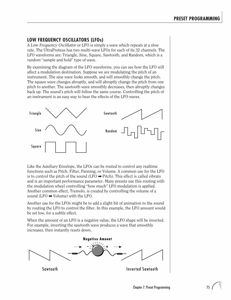
75Chapter 7: Preset Programming
PRESET PROGRAMMING
LOW FREQUENCY OSCILLATORS (LFOs)A Low Frequency Oscillator or LFO is simply a wave which repeats at a slow
rate. The UltraProteus has two multi-wave LFOs for each of its 32 channels. The
LFO waveforms are: Triangle, Sine, Square, Sawtooth, and Random, which is a
random “sample and hold” type of wave.
By examining the diagram of the LFO waveforms, you can see how the LFO will
affect a modulation destination. Suppose we are modulating the pitch of an
instrument. The sine wave looks smooth, and will smoothly change the pitch.
The square wave changes abruptly, and will abruptly change the pitch from one
pitch to another. The sawtooth wave smoothly decreases, then abruptly changes
back up. The sound’s pitch will follow the same course. Controlling the pitch of
an instrument is an easy way to hear the effects of the LFO waves.
Like the Auxiliary Envelope, the LFOs can be routed to control any realtime
functions such as Pitch, Filter, Panning, or Volume. A common use for the LFO
is to control the pitch of the sound (LFO Pitch). This effect is called vibrato
and is an important performance parameter. Many presets use this routing with
the modulation wheel controlling “how much” LFO modulation is applied.
Another common effect, Tremolo, is created by controlling the volume of a
sound (LFO Volume) with the LFO.
Another use for the LFOs might be to add a slight bit of animation to the sound
by routing the LFO to control the filter. In this example, the LFO amount would
be set low, for a subtle effect.
When the amount of an LFO is a negative value, the LFO shape will be inverted.
For example, inverting the sawtooth wave produces a wave that smoothly
increases, then instantly resets down.
T r i ang l e
Squa re
S i ne
Saw too th
Random
Inve r t ed Saw too th
Negat ive Amount
+-
Saw too th
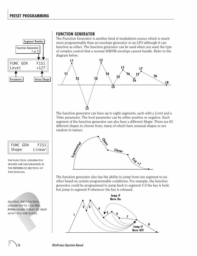
76 UltraProteus Operation Manual
PRESET PROGRAMMING
FUNCTION GENERATORThe Function Generator is another kind of modulation source which is much
more programmable than an envelope generator or an LFO although it can
function as either. The function generator can be used when you want the type
of complex control that a normal AHDSR envelope cannot handle. Refer to the
diagram below.
The function generator can have up to eight segments, each with a Level and a
Time parameter. The level parameter can be either positive or negative. Each
segment of the function generator can also have a different Shape. There are 63
different shapes to choose from, many of which have unusual shapes or are
random in nature.
The function generator also has the ability to jump from one segment to an-
other based on certain programmable conditions. For example, the function
generator could be programmed to jump back to segment 5 if the key is held,
but jump to segment 8 whenever the key is released.
L1
T1
L2
L3
L4
L5
L6
L7
L8T2 T3
T4T5
T6 T7 T8
Chaos
L inear
Expo
nent
ial
Exp +1
1
2 3
654
7
8
Jump ifNote On
Jump ifNote Off
FUNC GEN F1S1Level +127
FUNC GEN F1S1Shape Linear
THE FUNCTION GENERATORSHAPES ARE DIAGRAMMED INTHE REFERENCE SECTION OFTHIS MANUAL.
ROUTING THE FUNCTIONGENERATOR TO CONTROLPITCH MAKES IT EASY TO HEARWHAT YOU ARE DOING.
Pa rame te r
Segmen t Numbe r
Fun c t i on Gene ra t o r1 o r 2
Va l ue/Shape
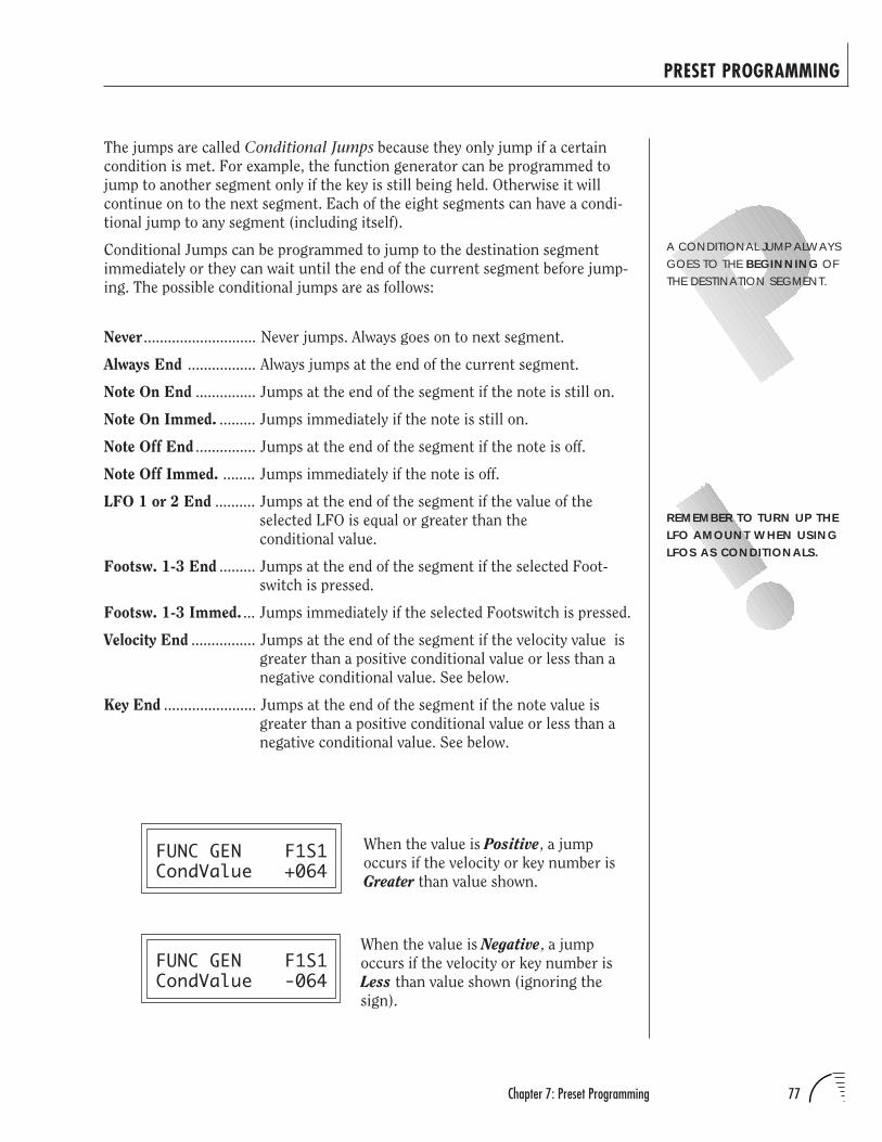
77Chapter 7: Preset Programming
PRESET PROGRAMMING
The jumps are called Conditional Jumps because they only jump if a certain
condition is met. For example, the function generator can be programmed to
jump to another segment only if the key is still being held. Otherwise it will
continue on to the next segment. Each of the eight segments can have a condi-
tional jump to any segment (including itself).
Conditional Jumps can be programmed to jump to the destination segment
immediately or they can wait until the end of the current segment before jump-
ing. The possible conditional jumps are as follows:
Never ............................ Never jumps. Always goes on to next segment.
Always End ................. Always jumps at the end of the current segment.
Note On End ............... Jumps at the end of the segment if the note is still on.
Note On Immed. ......... Jumps immediately if the note is still on.
Note Off End ............... Jumps at the end of the segment if the note is off.
Note Off Immed. ........ Jumps immediately if the note is off.
LFO 1 or 2 End .......... Jumps at the end of the segment if the value of the
selected LFO is equal or greater than the
conditional value.
Footsw. 1-3 End ......... Jumps at the end of the segment if the selected Foot-
switch is pressed.
Footsw. 1-3 Immed. ... Jumps immediately if the selected Footswitch is pressed.
Velocity End ................ Jumps at the end of the segment if the velocity value is
greater than a positive conditional value or less than a
negative conditional value. See below.
Key End ....................... Jumps at the end of the segment if the note value is
greater than a positive conditional value or less than a
negative conditional value. See below.
FUNC GEN F1S1CondValue +064
FUNC GEN F1S1CondValue -064
A CONDITIONAL JUMP ALWAYSGOES TO THE BEGINNING OFTHE DESTINATION SEGMENT.
REMEMBER TO TURN UP THELFO AMOUNT WHEN USINGLFOS AS CONDITIONALS.
When the value is Positive, a jump
occurs if the velocity or key number is
Greater than value shown.
When the value is Negative, a jump
occurs if the velocity or key number is
Less than value shown (ignoring the
sign).
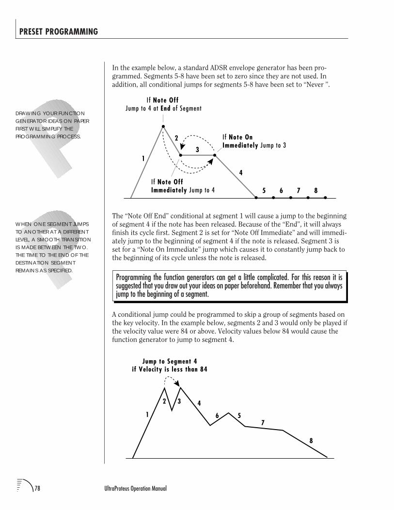
78 UltraProteus Operation Manual
PRESET PROGRAMMING
In the example below, a standard ADSR envelope generator has been pro-
grammed. Segments 5-8 have been set to zero since they are not used. In
addition, all conditional jumps for segments 5-8 have been set to “Never ”.
The “Note Off End” conditional at segment 1 will cause a jump to the beginning
of segment 4 if the note has been released. Because of the “End”, it will always
finish its cycle first. Segment 2 is set for “Note Off Immediate” and will immedi-
ately jump to the beginning of segment 4 if the note is released. Segment 3 is
set for a “Note On Immediate” jump which causes it to constantly jump back to
the beginning of its cycle unless the note is released.
Programming the function generators can get a little complicated. For this reason it issuggested that you draw out your ideas on paper beforehand. Remember that you alwaysjump to the beginning of a segment.
A conditional jump could be programmed to skip a group of segments based on
the key velocity. In the example below, segments 2 and 3 would only be played if
the velocity value were 84 or above. Velocity values below 84 would cause the
function generator to jump to segment 4.
WHEN ONE SEGMENT JUMPSTO ANOTHER AT A DIFFERENTLEVEL, A SMOOTH TRANSITIONIS MADE BETWEEN THE TWO.THE TIME TO THE END OF THEDESTINATION SEGMENTREMAINS AS SPECIFIED.
DRAWING YOUR FUNCTIONGENERATOR IDEAS ON PAPERFIRST WILL SIMPLIFY THEPROGRAMMING PROCESS.
1
2
3
4
I f Note Off Jump to 4 at End of Segment
5 6 7 8I f Note OffImmediately Jump to 4
I f Note OnImmediately Jump to 3
1
2 3
6 5
4
7
8
Jump to Segment 4if Velocity is less than 84
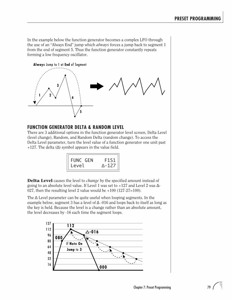
79Chapter 7: Preset Programming
PRESET PROGRAMMING
In the example below the function generator becomes a complex LFO through
the use of an “Always End” jump which always forces a jump back to segment 1
from the end of segment 5. Thus the function generator constantly repeats
forming a low frequency oscillator.
FUNCTION GENERATOR DELTA & RANDOM LEVELThere are 3 additional options in the function generator level screen, Delta Level
(level change), Random, and Random Delta (random change). To access the
Delta Level parameter, turn the level value of a function generator one unit past
+127. The delta (∆) symbol appears in the value field.
FUNC GEN F1S1Level ∆-127
Delta Level causes the level to change by the specified amount instead of
going to an absolute level value. If Level 1 was set to +127 and Level 2 was ∆-
027, then the resulting level 2 value would be +100 (127-27=100).
The ∆ Level parameter can be quite useful when looping segments. In the
example below, segment 3 has a level of ∆ -016 and loops back to itself as long as
the key is held. Because the level is a change rather than an absolute amount,
the level decreases by -16 each time the segment loops.
1 2
3
5
4
Always Jump to 1 at End of Segment
080I f Note On
Jump to 3
127
16
32
48
64
80
96
112 -016112
000
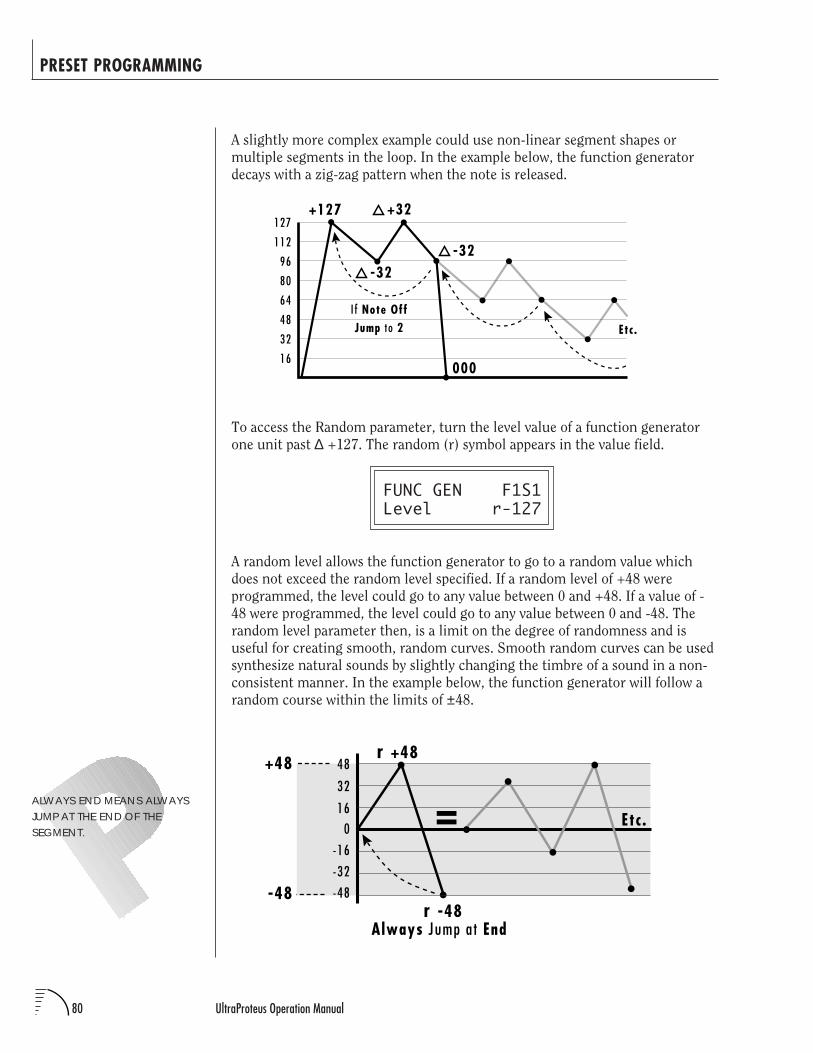
80 UltraProteus Operation Manual
PRESET PROGRAMMING
+48
-48
16
32
48
0
-16
-32
-48
Always Jump at End
= Etc.
r +48
r -48
A slightly more complex example could use non-linear segment shapes or
multiple segments in the loop. In the example below, the function generator
decays with a zig-zag pattern when the note is released.
To access the Random parameter, turn the level value of a function generator
one unit past ∆ +127. The random (r) symbol appears in the value field.
FUNC GEN F1S1Level r-127
A random level allows the function generator to go to a random value which
does not exceed the random level specified. If a random level of +48 were
programmed, the level could go to any value between 0 and +48. If a value of -
48 were programmed, the level could go to any value between 0 and -48. The
random level parameter then, is a limit on the degree of randomness and is
useful for creating smooth, random curves. Smooth random curves can be used
synthesize natural sounds by slightly changing the timbre of a sound in a non-
consistent manner. In the example below, the function generator will follow a
random course within the limits of ±48.
+127127
16
32
48
64
80
96
112
000
+32
-32-32
Etc.
I f Note OffJump to 2
ALWAYS END MEANS ALWAYSJUMP AT THE END OF THESEGMENT.
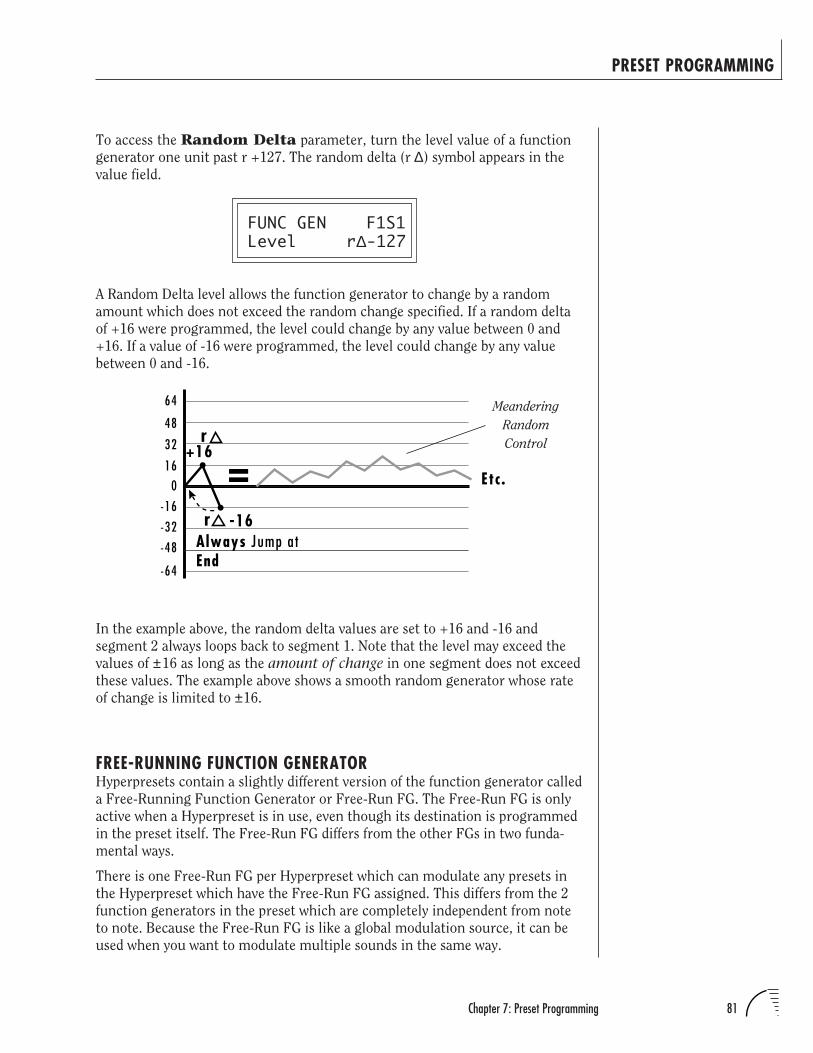
81Chapter 7: Preset Programming
PRESET PROGRAMMING
16
32
48
0
-16
-32
-48
64
-64
Always Jump atEnd
= Etc.
+16
-16
r
r
To access the Random Delta parameter, turn the level value of a function
generator one unit past r +127. The random delta (r ∆) symbol appears in the
value field.
FUNC GEN F1S1Level r∆-127
A Random Delta level allows the function generator to change by a random
amount which does not exceed the random change specified. If a random delta
of +16 were programmed, the level could change by any value between 0 and
+16. If a value of -16 were programmed, the level could change by any value
between 0 and -16.
Meandering
Random
Control
In the example above, the random delta values are set to +16 and -16 and
segment 2 always loops back to segment 1. Note that the level may exceed the
values of ±16 as long as the amount of change in one segment does not exceed
these values. The example above shows a smooth random generator whose rate
of change is limited to ±16.
FREE-RUNNING FUNCTION GENERATORHyperpresets contain a slightly different version of the function generator called
a Free-Running Function Generator or Free-Run FG. The Free-Run FG is only
active when a Hyperpreset is in use, even though its destination is programmed
in the preset itself. The Free-Run FG differs from the other FGs in two funda-
mental ways.
There is one Free-Run FG per Hyperpreset which can modulate any presets in
the Hyperpreset which have the Free-Run FG assigned. This differs from the 2
function generators in the preset which are completely independent from note
to note. Because the Free-Run FG is like a global modulation source, it can be
used when you want to modulate multiple sounds in the same way.
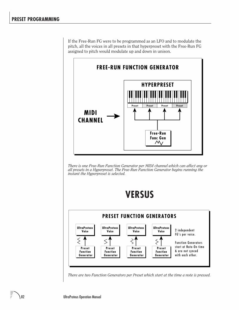
82 UltraProteus Operation Manual
PRESET PROGRAMMING
If the Free-Run FG were to be programmed as an LFO and to modulate the
pitch, all the voices in all presets in that hyperpreset with the Free-Run FG
assigned to pitch would modulate up and down in unison.
There are two Function Generators per Preset which start at the time a note is pressed.
VERSUS
There is one Free-Run Function Generator per MIDI channel which can affect any orall presets in a Hyperpreset. The Free-Run Function Generator begins running theinstant the Hyperpreset is selected.
FREE-RUN FUNCTION GENERATOR
MIDICHANNEL
Preset Preset Preset Preset
Free-RunFunc Gen
HYPERPRESET
UltraProteusVoice
PresetFunct ion
Generator
UltraProteusVoice
PresetFunct ion
Generator
UltraProteusVoice
PresetFunct ion
Generator
UltraProteusVoice
PresetFunct ion
Generator
PRESET FUNCTION GENERATORS
2 i ndependen tFG ' s pe r vo i c e .
Fun c t i on Gene ra t o r ss t a r t a t No t e -On t ime& a re no t s yn cedw i t h ea ch o t he r .
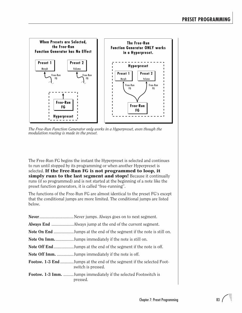
83Chapter 7: Preset Programming
PRESET PROGRAMMING
The Free-Run Function Generator only works in a Hyperpreset, even though themodulation routing is made in the preset.
The Free-Run FG begins the instant the Hyperpreset is selected and continues
to run until stopped by its programming or when another Hyperpreset is
selected. If the Free-Run FG is not programmed to loop, itsimply runs to the last segment and stops! Because it continually
runs (if so programmed) and is not started at the beginning of a note like the
preset function generators, it is called “free-running”.
The functions of the Free-Run FG are almost identical to the preset FG's except
that the conditional jumps are more limited. The conditional jumps are listed
below.
Never ...............................Never jumps. Always goes on to next segment.
Always End ....................Always jump at the end of the current segment.
Note On End ..................Jumps at the end of the segment if the note is still on.
Note On Imm. ................Jumps immediately if the note is still on.
Note Off End ..................Jumps at the end of the segment if the note is off.
Note Off Imm. ............... Jumps immediately if the note is off.
Footsw. 1-3 End ............Jumps at the end of the segment if the selected Foot-
switch is pressed.
Footsw. 1-3 Imm. ......... Jumps immediately if the selected Footswitch is
pressed.
Morph
Preset 1Volume
Preset 2
The Free-RunFunction Generator ONLY works
in a Hyperpreset.
Free-RunFG
Hyperpreset
Free-RunFG
Free-RunFG
Morph
Preset 1Volume
Preset 2
When Presets are Selected,the Free-Run
Function Generator has No Effect
Free-RunFG
Hyperpreset
Free-RunFG
Free-RunFG

83Chapter 7: Preset Programming
PRESET PROGRAMMING
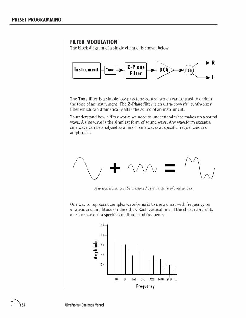
84 UltraProteus Operation Manual
PRESET PROGRAMMING
The Tone filter is a simple low-pass tone control which can be used to darken
the tone of an instrument. The Z-Plane filter is an ultra-powerful synthesizer
filter which can dramatically alter the sound of an instrument.
To understand how a filter works we need to understand what makes up a sound
wave. A sine wave is the simplest form of sound wave. Any waveform except a
sine wave can be analyzed as a mix of sine waves at specific frequencies and
amplitudes.
One way to represent complex waveforms is to use a chart with frequency on
one axis and amplitude on the other. Each vertical line of the chart represents
one sine wave at a specific amplitude and frequency.
Any waveform can be analyzed as a mixture of sine waves.
FILTER MODULATIONThe block diagram of a single channel is shown below.
R
LPanInstrument Tone DCAZ-Plane
Fi lter
20
40
60
80
100
40 80 160 360 720 1440 2880
Frequency
. . .
Ampl
itud
e
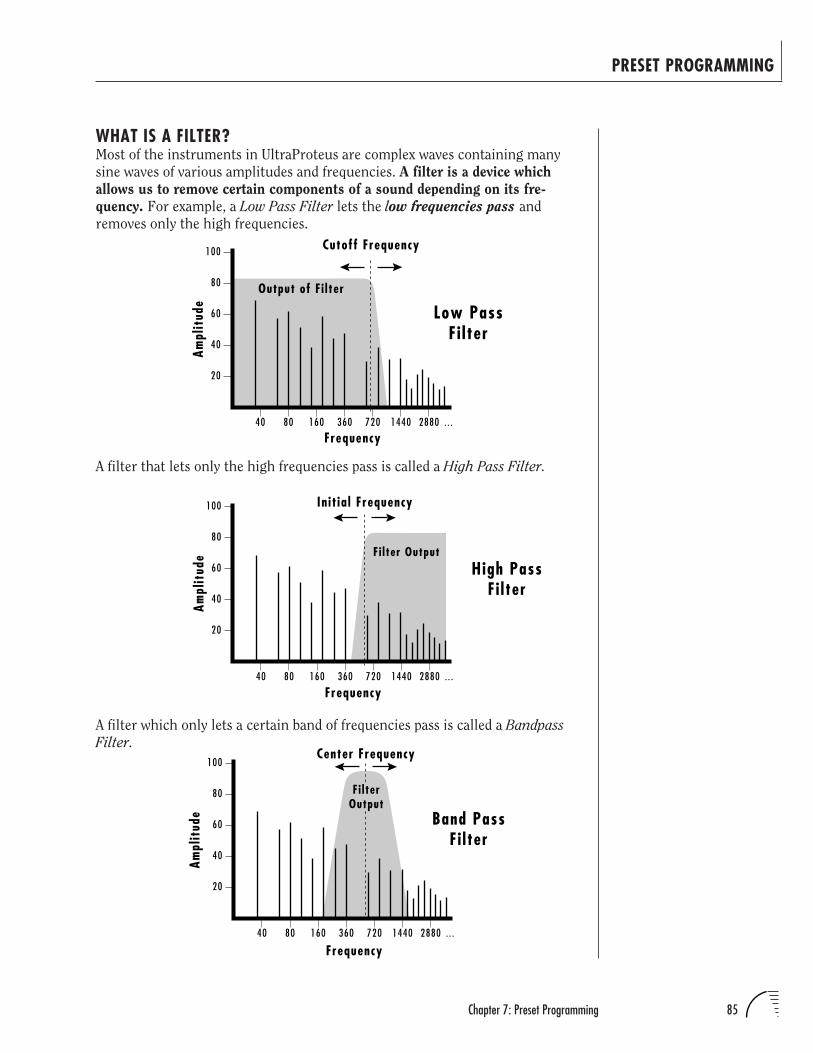
85Chapter 7: Preset Programming
PRESET PROGRAMMING
20
40
60
80
100
40 80 160 360 720 1440 2880
Frequency. . .
Ampl
itud
e
Center Frequency
Fi lterOutput
Band PassFi lter
WHAT IS A FILTER?Most of the instruments in UltraProteus are complex waves containing many
sine waves of various amplitudes and frequencies. A filter is a device which
allows us to remove certain components of a sound depending on its fre-
quency. For example, a Low Pass Filter lets the low frequencies pass and
removes only the high frequencies.
20
40
60
80
100
40 80 160 360 720 1440 2880
Frequency. . .
Ampl
itud
e
Output of Fi lter
Low PassFi lter
Cutoff Frequency
A filter that lets only the high frequencies pass is called a High Pass Filter.
20
40
60
80
100
40 80 160 360 720 1440 2880
Frequency. . .
Ampl
itud
e F i l ter Output
Init ial Frequency
High PassFi lter
A filter which only lets a certain band of frequencies pass is called a Bandpass
Filter.
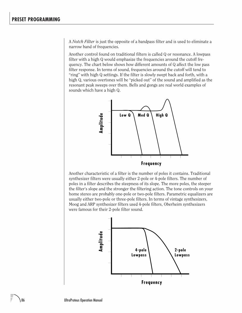
86 UltraProteus Operation Manual
PRESET PROGRAMMING
A Notch Filter is just the opposite of a bandpass filter and is used to eliminate a
narrow band of frequencies.
Another control found on traditional filters is called Q or resonance. A lowpass
filter with a high Q would emphasize the frequencies around the cutoff fre-
quency. The chart below shows how different amounts of Q affect the low pass
filter response. In terms of sound, frequencies around the cutoff will tend to
“ring” with high Q settings. If the filter is slowly swept back and forth, with a
high Q, various overtones will be “picked out” of the sound and amplified as the
resonant peak sweeps over them. Bells and gongs are real world examples of
sounds which have a high Q.
Another characteristic of a filter is the number of poles it contains. Traditional
synthesizer filters were usually either 2-pole or 4-pole filters. The number of
poles in a filter describes the steepness of its slope. The more poles, the steeper
the filter's slope and the stronger the filtering action. The tone controls on your
home stereo are probably one-pole or two-pole filters. Parametric equalizers are
usually either two-pole or three-pole filters. In terms of vintage synthesizers,
Moog and ARP synthesizer filters used 4-pole filters, Oberheim synthesizers
were famous for their 2-pole filter sound.
Frequency
Ampl
itud
e Low Q Med Q High Q
Frequency
Ampl
itud
e
4-poleLowpass
2-poleLowpass
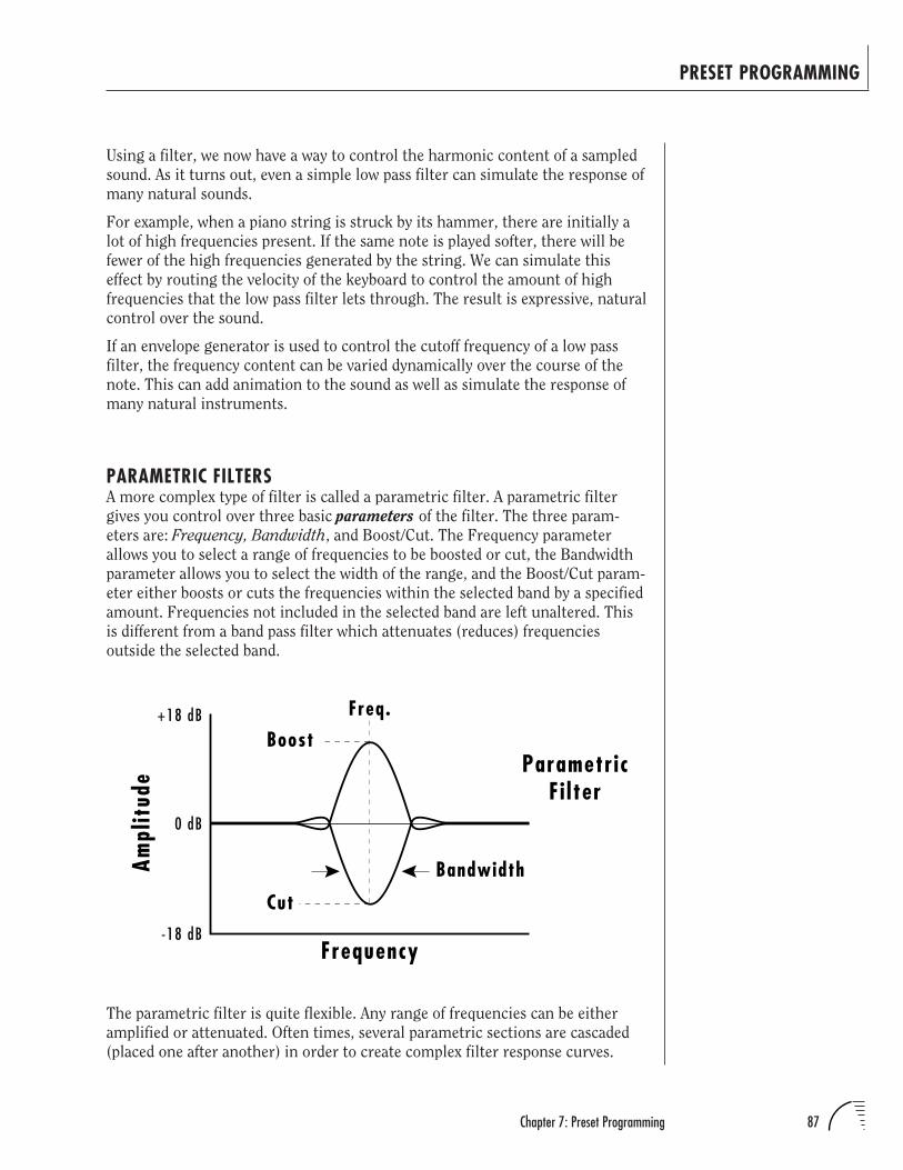
87Chapter 7: Preset Programming
PRESET PROGRAMMING
Using a filter, we now have a way to control the harmonic content of a sampled
sound. As it turns out, even a simple low pass filter can simulate the response of
many natural sounds.
For example, when a piano string is struck by its hammer, there are initially a
lot of high frequencies present. If the same note is played softer, there will be
fewer of the high frequencies generated by the string. We can simulate this
effect by routing the velocity of the keyboard to control the amount of high
frequencies that the low pass filter lets through. The result is expressive, natural
control over the sound.
If an envelope generator is used to control the cutoff frequency of a low pass
filter, the frequency content can be varied dynamically over the course of the
note. This can add animation to the sound as well as simulate the response of
many natural instruments.
PARAMETRIC FILTERSA more complex type of filter is called a parametric filter. A parametric filter
gives you control over three basic parameters of the filter. The three param-
eters are: Frequency, Bandwidth, and Boost/Cut. The Frequency parameter
allows you to select a range of frequencies to be boosted or cut, the Bandwidth
parameter allows you to select the width of the range, and the Boost/Cut param-
eter either boosts or cuts the frequencies within the selected band by a specified
amount. Frequencies not included in the selected band are left unaltered. This
is different from a band pass filter which attenuates (reduces) frequencies
outside the selected band.
The parametric filter is quite flexible. Any range of frequencies can be either
amplified or attenuated. Often times, several parametric sections are cascaded
(placed one after another) in order to create complex filter response curves.
Boost
Cut
Freq.
0 dB
+18 dB
-18 dB
Bandwidth
Frequency
Ampl
itud
e ParametricFi lter
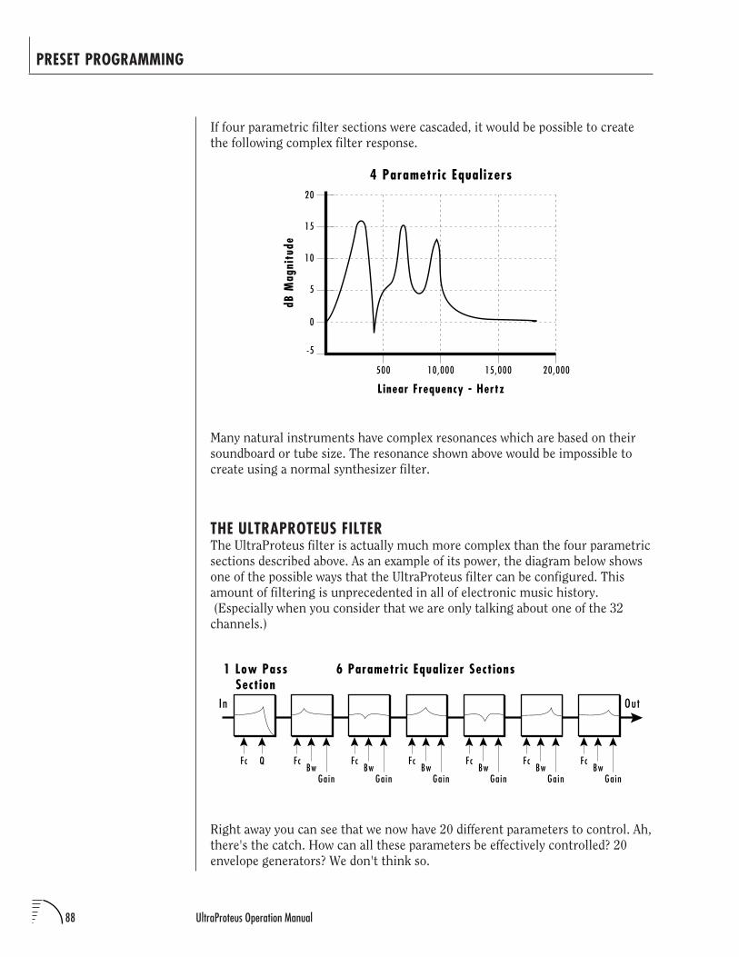
88 UltraProteus Operation Manual
PRESET PROGRAMMING
If four parametric filter sections were cascaded, it would be possible to create
the following complex filter response.
Many natural instruments have complex resonances which are based on their
soundboard or tube size. The resonance shown above would be impossible to
create using a normal synthesizer filter.
THE ULTRAPROTEUS FILTERThe UltraProteus filter is actually much more complex than the four parametric
sections described above. As an example of its power, the diagram below shows
one of the possible ways that the UltraProteus filter can be configured. This
amount of filtering is unprecedented in all of electronic music history.
(Especially when you consider that we are only talking about one of the 32
channels.)
Right away you can see that we now have 20 different parameters to control. Ah,
there's the catch. How can all these parameters be effectively controlled? 20
envelope generators? We don't think so.
10
Linear Frequency - Hertz
dB M
agni
tude
-5
0
5
15
20
500 10,000 15,000 20,000
4 Parametric Equal izers
In Out
6 Parametric Equal izer Sections1 Low PassSection
Fc Q FcBw
Gain
FcBw
Gain
FcBw
Gain
FcBw
Gain
FcBw
Gain
FcBw
Gain
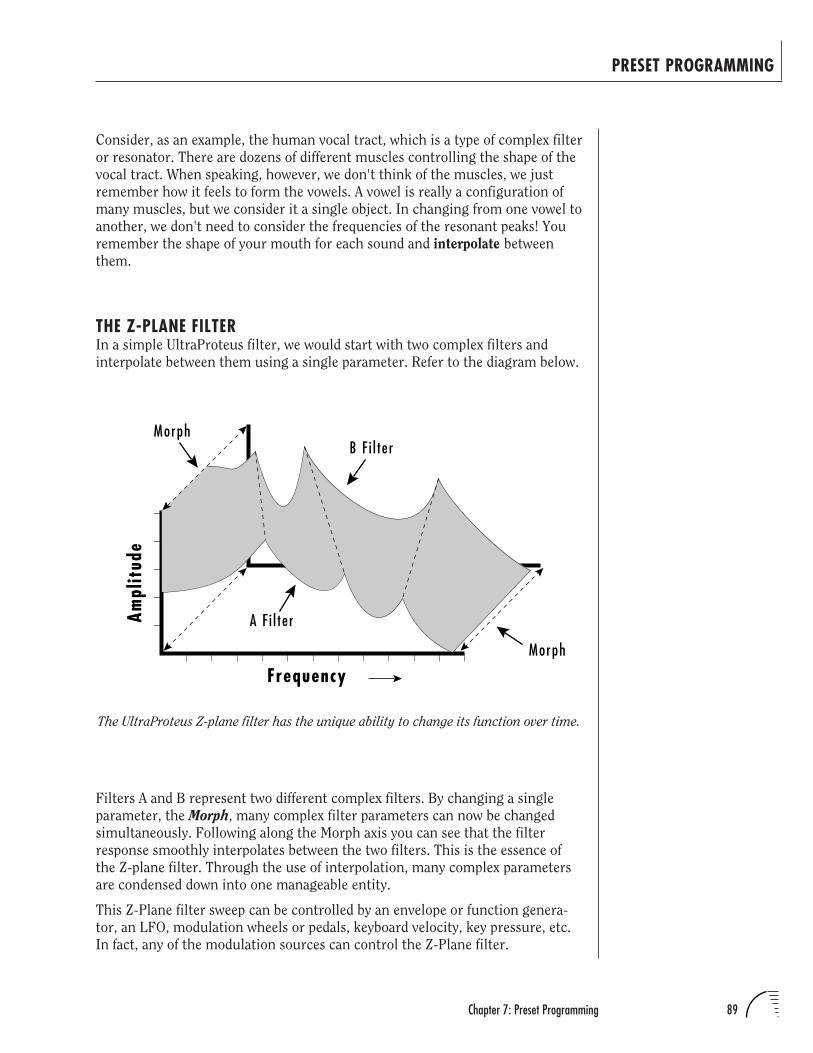
89Chapter 7: Preset Programming
PRESET PROGRAMMING
Consider, as an example, the human vocal tract, which is a type of complex filter
or resonator. There are dozens of different muscles controlling the shape of the
vocal tract. When speaking, however, we don't think of the muscles, we just
remember how it feels to form the vowels. A vowel is really a configuration of
many muscles, but we consider it a single object. In changing from one vowel to
another, we don't need to consider the frequencies of the resonant peaks! You
remember the shape of your mouth for each sound and interpolate between
them.
THE Z-PLANE FILTERIn a simple UltraProteus filter, we would start with two complex filters and
interpolate between them using a single parameter. Refer to the diagram below.
Filters A and B represent two different complex filters. By changing a single
parameter, the Morph, many complex filter parameters can now be changed
simultaneously. Following along the Morph axis you can see that the filter
response smoothly interpolates between the two filters. This is the essence of
the Z-plane filter. Through the use of interpolation, many complex parameters
are condensed down into one manageable entity.
This Z-Plane filter sweep can be controlled by an envelope or function genera-
tor, an LFO, modulation wheels or pedals, keyboard velocity, key pressure, etc.
In fact, any of the modulation sources can control the Z-Plane filter.
Frequency
Ampl
itud
e
Morph
A F i l ter
B F i l ter
Morph
The UltraProteus Z-plane filter has the unique ability to change its function over time.
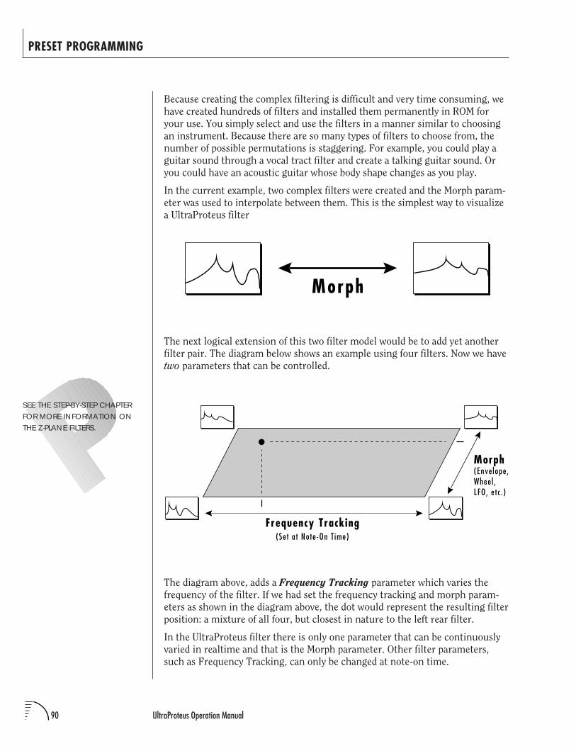
90 UltraProteus Operation Manual
PRESET PROGRAMMING
Because creating the complex filtering is difficult and very time consuming, we
have created hundreds of filters and installed them permanently in ROM for
your use. You simply select and use the filters in a manner similar to choosing
an instrument. Because there are so many types of filters to choose from, the
number of possible permutations is staggering. For example, you could play a
guitar sound through a vocal tract filter and create a talking guitar sound. Or
you could have an acoustic guitar whose body shape changes as you play.
In the current example, two complex filters were created and the Morph param-
eter was used to interpolate between them. This is the simplest way to visualize
a UltraProteus filter
The next logical extension of this two filter model would be to add yet another
filter pair. The diagram below shows an example using four filters. Now we have
two parameters that can be controlled.
SEE THE STEP-BY-STEP CHAPTERFOR MORE INFORMATION ONTHE Z-PLANE FILTERS.
Morph
The diagram above, adds a Frequency Tracking parameter which varies the
frequency of the filter. If we had set the frequency tracking and morph param-
eters as shown in the diagram above, the dot would represent the resulting filter
position: a mixture of all four, but closest in nature to the left rear filter.
In the UltraProteus filter there is only one parameter that can be continuously
varied in realtime and that is the Morph parameter. Other filter parameters,
such as Frequency Tracking, can only be changed at note-on time.
Frequency Tracking
Morph(Envelope,Wheel ,LFO, e tc . )
(Set a t Note-On T ime)
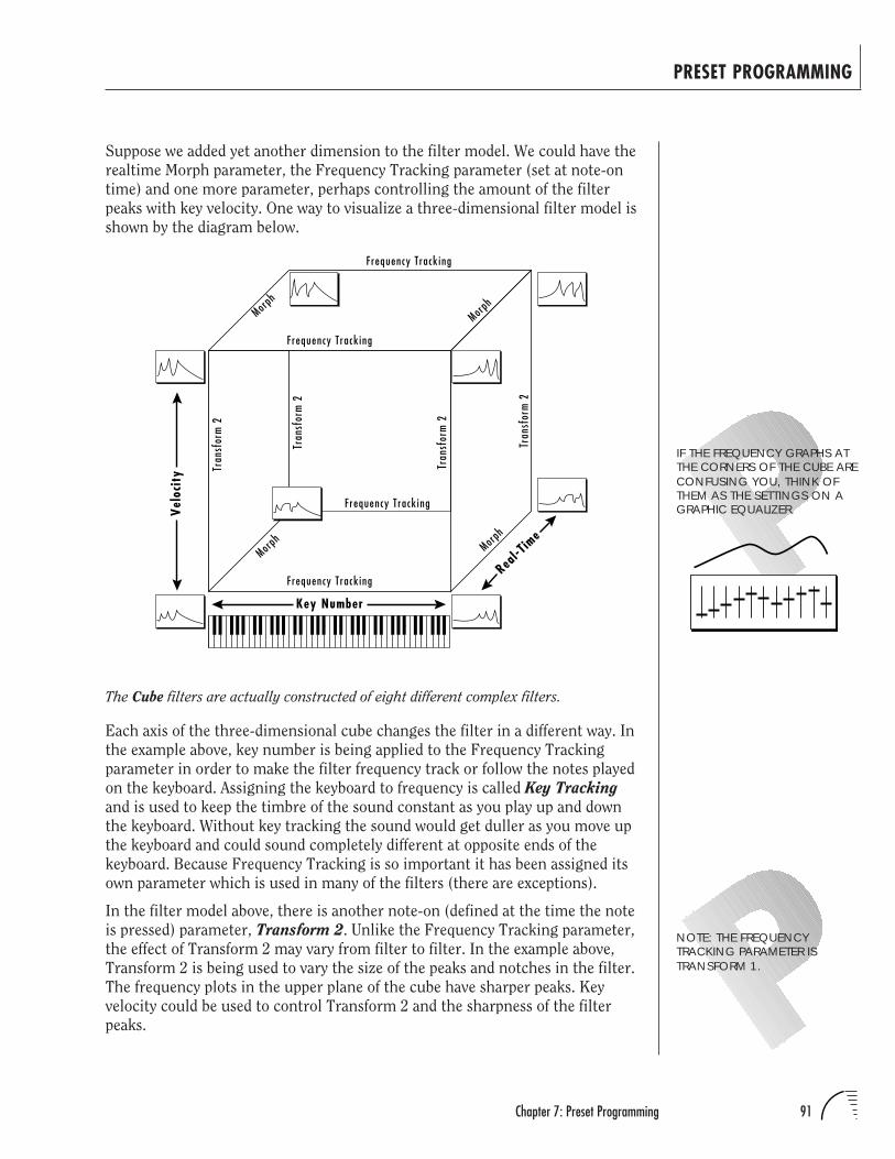
91Chapter 7: Preset Programming
PRESET PROGRAMMING
Suppose we added yet another dimension to the filter model. We could have the
realtime Morph parameter, the Frequency Tracking parameter (set at note-on
time) and one more parameter, perhaps controlling the amount of the filter
peaks with key velocity. One way to visualize a three-dimensional filter model is
shown by the diagram below.
NOTE: THE FREQUENCYTRACKING PARAMETER ISTRANSFORM 1.
Each axis of the three-dimensional cube changes the filter in a different way. In
the example above, key number is being applied to the Frequency Tracking
parameter in order to make the filter frequency track or follow the notes played
on the keyboard. Assigning the keyboard to frequency is called Key Tracking
and is used to keep the timbre of the sound constant as you play up and down
the keyboard. Without key tracking the sound would get duller as you move up
the keyboard and could sound completely different at opposite ends of the
keyboard. Because Frequency Tracking is so important it has been assigned its
own parameter which is used in many of the filters (there are exceptions).
In the filter model above, there is another note-on (defined at the time the note
is pressed) parameter, Transform 2. Unlike the Frequency Tracking parameter,
the effect of Transform 2 may vary from filter to filter. In the example above,
Transform 2 is being used to vary the size of the peaks and notches in the filter.
The frequency plots in the upper plane of the cube have sharper peaks. Key
velocity could be used to control Transform 2 and the sharpness of the filter
peaks.
The Cube filters are actually constructed of eight different complex filters.
Key Number
Frequency Track ing
Tran
sfor
m 2
Vel
ocit
y
Morph
Morph
Tran
sfor
m 2
Tran
sfor
m 2
Morph
Tran
sfor
m 2
Real-T
ime
Morph
Frequency Track ing
Frequency Track ing
Frequency Track ing
IF THE FREQUENCY GRAPHS ATTHE CORNERS OF THE CUBE ARECONFUSING YOU, THINK OFTHEM AS THE SETTINGS ON AGRAPHIC EQUALIZER.
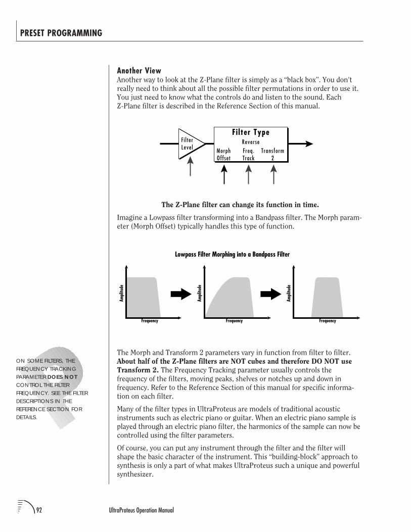
92 UltraProteus Operation Manual
PRESET PROGRAMMING
Another ViewAnother way to look at the Z-Plane filter is simply as a “black box”. You don't
really need to think about all the possible filter permutations in order to use it.
You just need to know what the controls do and listen to the sound. Each
Z-Plane filter is described in the Reference Section of this manual.
The Morph and Transform 2 parameters vary in function from filter to filter.
About half of the Z-Plane filters are NOT cubes and therefore DO NOT use
Transform 2. The Frequency Tracking parameter usually controls the
frequency of the filters, moving peaks, shelves or notches up and down in
frequency. Refer to the Reference Section of this manual for specific informa-
tion on each filter.
Many of the filter types in UltraProteus are models of traditional acoustic
instruments such as electric piano or guitar. When an electric piano sample is
played through an electric piano filter, the harmonics of the sample can now be
controlled using the filter parameters.
Of course, you can put any instrument through the filter and the filter will
shape the basic character of the instrument. This “building-block” approach to
synthesis is only a part of what makes UltraProteus such a unique and powerful
synthesizer.
ON SOME FILTERS, THEFREQUENCY TRACKINGPARAMETER DOES NOTCONTROL THE FILTERFREQUENCY. SEE THE FILTERDESCRIPTIONS IN THEREFERENCE SECTION FORDETAILS.
F i l terLeve l Morph
OffsetFreq.Track
Transform2
ReverseFi lter Type
The Z-Plane filter can change its function in time.
Imagine a Lowpass filter transforming into a Bandpass filter. The Morph param-
eter (Morph Offset) typically handles this type of function.
Lowpass Filter Morphing into a Bandpass Filter
Frequency
Ampl
itude
Frequency
Ampl
itude
Frequency
Ampl
itude
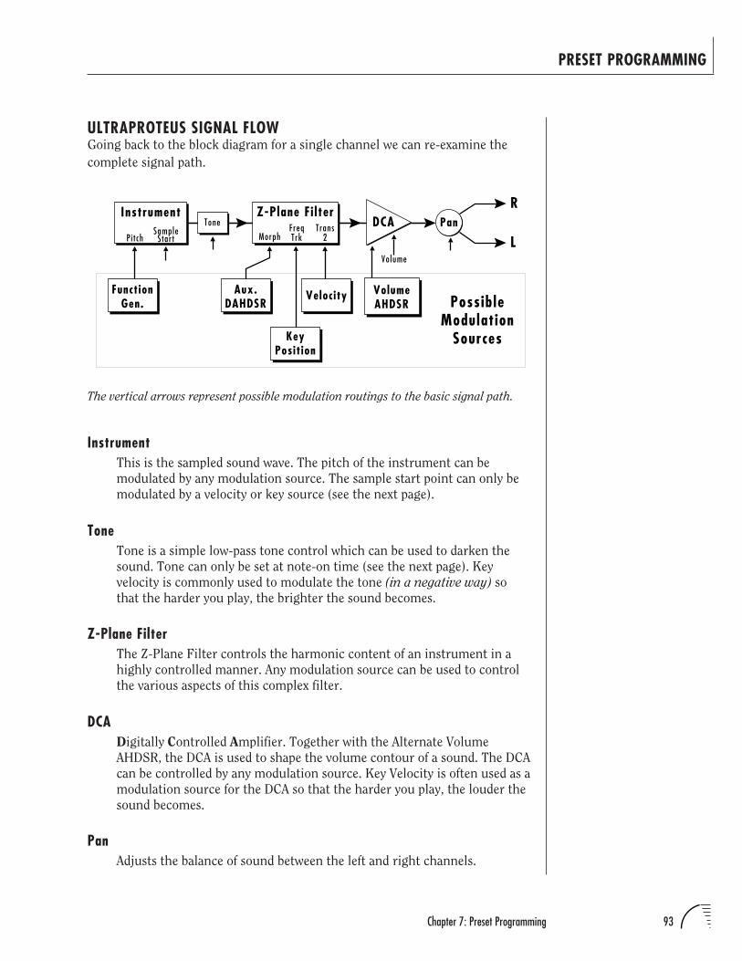
93Chapter 7: Preset Programming
PRESET PROGRAMMING
ULTRAPROTEUS SIGNAL FLOWGoing back to the block diagram for a single channel we can re-examine the
complete signal path.
InstrumentThis is the sampled sound wave. The pitch of the instrument can be
modulated by any modulation source. The sample start point can only be
modulated by a velocity or key source (see the next page).
ToneTone is a simple low-pass tone control which can be used to darken the
sound. Tone can only be set at note-on time (see the next page). Key
velocity is commonly used to modulate the tone (in a negative way) so
that the harder you play, the brighter the sound becomes.
Z-Plane FilterThe Z-Plane Filter controls the harmonic content of an instrument in a
highly controlled manner. Any modulation source can be used to control
the various aspects of this complex filter.
DCADigitally Controlled Amplifier. Together with the Alternate Volume
AHDSR, the DCA is used to shape the volume contour of a sound. The DCA
can be controlled by any modulation source. Key Velocity is often used as a
modulation source for the DCA so that the harder you play, the louder the
sound becomes.
PanAdjusts the balance of sound between the left and right channels.
R
LVolume
Pan
VolumeAHDSR
Instrument
Pi t chSample
Star t
ToneZ-Plane Fi lter
DCA
Aux.DAHDSR
Velocity
MorphFreqTrk
FunctionGen. Possible
ModulationSources
Trans2
KeyPosit ion
The vertical arrows represent possible modulation routings to the basic signal path.
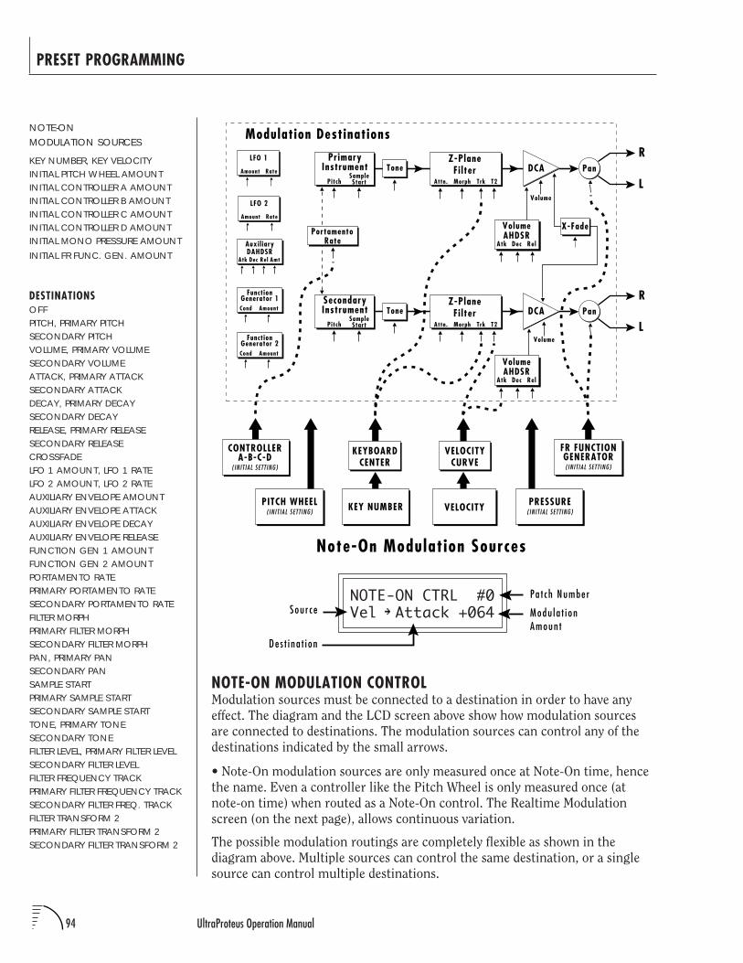
94 UltraProteus Operation Manual
PRESET PROGRAMMING
NOTE-ON CTRL #0Vel Attack +064
NOTE-ON MODULATION CONTROLModulation sources must be connected to a destination in order to have any
effect. The diagram and the LCD screen above show how modulation sources
are connected to destinations. The modulation sources can control any of the
destinations indicated by the small arrows.
• Note-On modulation sources are only measured once at Note-On time, hence
the name. Even a controller like the Pitch Wheel is only measured once (at
note-on time) when routed as a Note-On control. The Realtime Modulation
screen (on the next page), allows continuous variation.
The possible modulation routings are completely flexible as shown in the
diagram above. Multiple sources can control the same destination, or a single
source can control multiple destinations.
NOTE-ONMODULATION SOURCES
KEY NUMBER, KEY VELOCITYINITIAL PITCH WHEEL AMOUNTINITIAL CONTROLLER A AMOUNTINITIAL CONTROLLER B AMOUNTINITIAL CONTROLLER C AMOUNTINITIAL CONTROLLER D AMOUNTINITIAL MONO PRESSURE AMOUNTINITIAL FR FUNC. GEN. AMOUNT
DESTINATIONSOFFPITCH, PRIMARY PITCHSECONDARY PITCHVOLUME, PRIMARY VOLUMESECONDARY VOLUMEATTACK, PRIMARY ATTACKSECONDARY ATTACKDECAY, PRIMARY DECAYSECONDARY DECAYRELEASE, PRIMARY RELEASESECONDARY RELEASECROSSFADELFO 1 AMOUNT, LFO 1 RATELFO 2 AMOUNT, LFO 2 RATEAUXILIARY ENVELOPE AMOUNTAUXILIARY ENVELOPE ATTACKAUXILIARY ENVELOPE DECAYAUXILIARY ENVELOPE RELEASEFUNCTION GEN 1 AMOUNTFUNCTION GEN 2 AMOUNTPORTAMENTO RATEPRIMARY PORTAMENTO RATESECONDARY PORTAMENTO RATEFILTER MORPHPRIMARY FILTER MORPHSECONDARY FILTER MORPHPAN, PRIMARY PANSECONDARY PANSAMPLE STARTPRIMARY SAMPLE STARTSECONDARY SAMPLE STARTTONE, PRIMARY TONESECONDARY TONEFILTER LEVEL, PRIMARY FILTER LEVELSECONDARY FILTER LEVELFILTER FREQUENCY TRACKPRIMARY FILTER FREQUENCY TRACKSECONDARY FILTER FREQ. TRACKFILTER TRANSFORM 2PRIMARY FILTER TRANSFORM 2SECONDARY FILTER TRANSFORM 2
LFO 1
Amount Rate
LFO 2
Amount Rate
R
LVolume
PanPrimary
InstrumentPitch
SampleStart
Tone
VELOCITY
VELOCITYCURVE
KEY NUMBER
KEYBOARDCENTER
Note-On Modulation Sources
X-Fade
Atk Dec Rel
VolumeAHDSR
R
LVolume
PanSecondaryInstrument
PitchSampleStart
Tone
Atk Dec Rel
VolumeAHDSR
PortamentoRate
DCA
DCA
Modulation Destinations
Auxil iaryDAHDSR
AmtAtk Dec Rel
CONTROLLERA-B-C-D
( INIT IAL SETTING)
PRESSURE( INIT IAL SETTING)
FR FUNCTIONGENERATOR( INIT IAL SETTING)
PITCH WHEEL( INIT IAL SETTING)
FunctionGenerator 1
AmountCond
FunctionGenerator 2
AmountCond
Z-PlaneFi lter
T2TrkMorphAttn.
Z-PlaneFi lter
T2TrkMorphAttn.
Sou r c ePa t ch Numbe r
Modu l a t i onAmoun t
De s t i na t i on
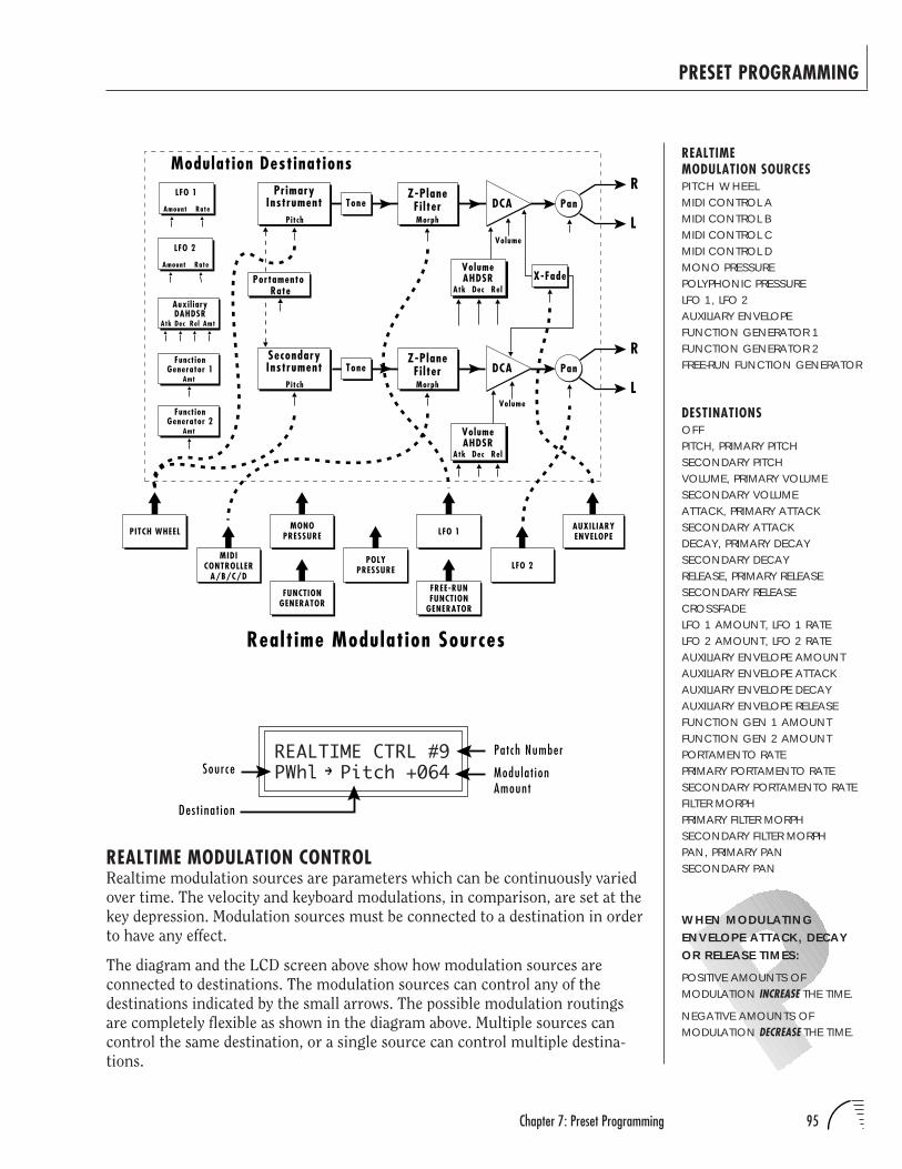
95Chapter 7: Preset Programming
PRESET PROGRAMMING
REALTIMEMODULATION SOURCESPITCH WHEELMIDI CONTROL AMIDI CONTROL BMIDI CONTROL CMIDI CONTROL DMONO PRESSUREPOLYPHONIC PRESSURELFO 1, LFO 2AUXILIARY ENVELOPEFUNCTION GENERATOR 1FUNCTION GENERATOR 2FREE-RUN FUNCTION GENERATOR
DESTINATIONSOFFPITCH, PRIMARY PITCHSECONDARY PITCHVOLUME, PRIMARY VOLUMESECONDARY VOLUMEATTACK, PRIMARY ATTACKSECONDARY ATTACKDECAY, PRIMARY DECAYSECONDARY DECAYRELEASE, PRIMARY RELEASESECONDARY RELEASECROSSFADELFO 1 AMOUNT, LFO 1 RATELFO 2 AMOUNT, LFO 2 RATEAUXILIARY ENVELOPE AMOUNTAUXILIARY ENVELOPE ATTACKAUXILIARY ENVELOPE DECAYAUXILIARY ENVELOPE RELEASEFUNCTION GEN 1 AMOUNTFUNCTION GEN 2 AMOUNTPORTAMENTO RATEPRIMARY PORTAMENTO RATESECONDARY PORTAMENTO RATEFILTER MORPHPRIMARY FILTER MORPHSECONDARY FILTER MORPHPAN, PRIMARY PANSECONDARY PAN
REALTIME CTRL #9PWhl Pitch +064
REALTIME MODULATION CONTROLRealtime modulation sources are parameters which can be continuously varied
over time. The velocity and keyboard modulations, in comparison, are set at the
key depression. Modulation sources must be connected to a destination in order
to have any effect.
The diagram and the LCD screen above show how modulation sources are
connected to destinations. The modulation sources can control any of the
destinations indicated by the small arrows. The possible modulation routings
are completely flexible as shown in the diagram above. Multiple sources can
control the same destination, or a single source can control multiple destina-
tions.
Realt ime Modulation Sources
POLYPRESSURE
MONOPRESSURE
MIDICONTROLLER
A/B/C/DLFO 2
AUXILIARYENVELOPELFO 1PITCH WHEEL
Auxil iaryDAHDSR
AmtAtk Dec Rel
LFO 1
Amount Rate
LFO 2
Amount Rate
Modulation DestinationsR
LVolume
Pan
Atk Dec Rel
VolumeAHDSR
PrimaryInstrument
Pitch
ToneZ-Plane
Fi lter
X-Fade
R
LVolume
Pan
Atk Dec Rel
VolumeAHDSR
SecondaryInstrument
Pitch
ToneZ-Plane
Fi lter
Morph
Morph
PortamentoRate
DCA
DCA
FUNCTIONGENERATOR
FREE-RUNFUNCTION
GENERATOR
FunctionGenerator 1
Amt
FunctionGenerator 2
Amt
WHEN MODULATINGENVELOPE ATTACK, DECAYOR RELEASE TIMES:
POSITIVE AMOUNTS OFMODULATION INCREASE THE TIME.
NEGATIVE AMOUNTS OFMODULATION DECREASE THE TIME.
SourcePatch Number
Modulat ionAmount
Dest inat ion
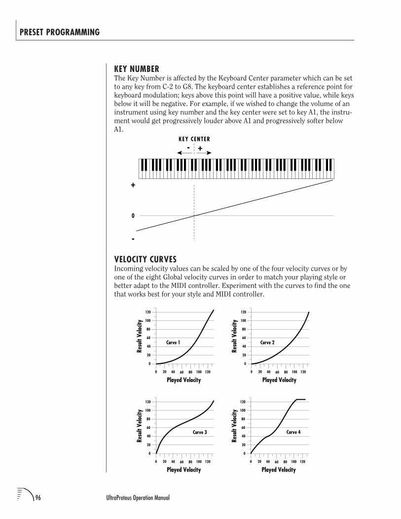
96 UltraProteus Operation Manual
PRESET PROGRAMMING
KEY NUMBERThe Key Number is affected by the Keyboard Center parameter which can be set
to any key from C-2 to G8. The keyboard center establishes a reference point for
keyboard modulation; keys above this point will have a positive value, while keys
below it will be negative. For example, if we wished to change the volume of an
instrument using key number and the key center were set to key A1, the instru-
ment would get progressively louder above A1 and progressively softer below
A1.
VELOCITY CURVESIncoming velocity values can be scaled by one of the four velocity curves or by
one of the eight Global velocity curves in order to match your playing style or
better adapt to the MIDI controller. Experiment with the curves to find the one
that works best for your style and MIDI controller.
Curve 1
0
20
40
60
80
100
120
0 20 40 60 80 100
Played Velocity120
Resu
lt Ve
locit
y
Curve 2
0
20
40
60
80
100
120
0 20 40 60 80 100
Played Velocity120
Resu
lt Ve
locit
y
Curve 3
0
20
40
60
80
100
120
0 20 40 60 80 100
Played Velocity120
Resu
lt Ve
locit
y
0
20
40
60
80
100
120
0 20 40 60 80 100
Played Velocity120
Resu
lt Ve
locit
y
Curve 4
KEY CENTER
+
-
0
-
+
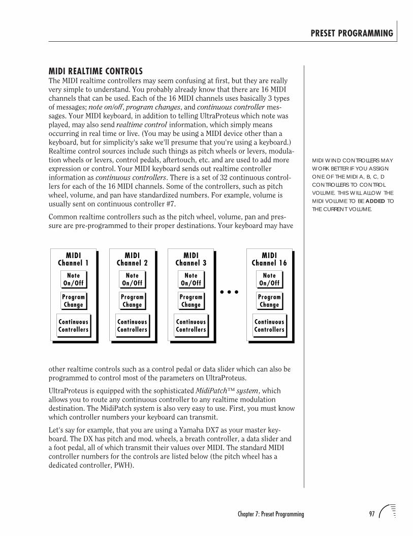
97Chapter 7: Preset Programming
PRESET PROGRAMMING
MIDI REALTIME CONTROLSThe MIDI realtime controllers may seem confusing at first, but they are really
very simple to understand. You probably already know that there are 16 MIDI
channels that can be used. Each of the 16 MIDI channels uses basically 3 types
of messages; note on/off, program changes, and continuous controller mes-
sages. Your MIDI keyboard, in addition to telling UltraProteus which note was
played, may also send realtime control information, which simply means
occurring in real time or live. (You may be using a MIDI device other than a
keyboard, but for simplicity's sake we'll presume that you're using a keyboard.)
Realtime control sources include such things as pitch wheels or levers, modula-
tion wheels or levers, control pedals, aftertouch, etc. and are used to add more
expression or control. Your MIDI keyboard sends out realtime controller
information as continuous controllers. There is a set of 32 continuous control-
lers for each of the 16 MIDI channels. Some of the controllers, such as pitch
wheel, volume, and pan have standardized numbers. For example, volume is
usually sent on continuous controller #7.
Common realtime controllers such as the pitch wheel, volume, pan and pres-
sure are pre-programmed to their proper destinations. Your keyboard may have
MIDI WIND CONTROLLERS MAYWORK BETTER IF YOU ASSIGNONE OF THE MIDI A, B, C, DCONTROLLERS TO CONTROLVOLUME. THIS WILL ALLOW THEMIDI VOLUME TO BE ADDED TOTHE CURRENT VOLUME.
NoteOn/Off
ContinuousControl lers
MIDIChannel 16
ProgramChange
NoteOn/Off
ContinuousControl lers
MIDIChannel 3
ProgramChange
NoteOn/Off
ContinuousControl lers
MIDIChannel 2
ProgramChange
NoteOn/Off
ContinuousControl lers
MIDIChannel 1
ProgramChange
other realtime controls such as a control pedal or data slider which can also be
programmed to control most of the parameters on UltraProteus.
UltraProteus is equipped with the sophisticated MidiPatch™ system, which
allows you to route any continuous controller to any realtime modulation
destination. The MidiPatch system is also very easy to use. First, you must know
which controller numbers your keyboard can transmit.
Let's say for example, that you are using a Yamaha DX7 as your master key-
board. The DX has pitch and mod. wheels, a breath controller, a data slider and
a foot pedal, all of which transmit their values over MIDI. The standard MIDI
controller numbers for the controls are listed below (the pitch wheel has a
dedicated controller, PWH).
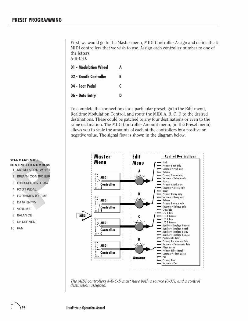
98 UltraProteus Operation Manual
PRESET PROGRAMMING
The MIDI controllers A-B-C-D must have both a source (0-31), and a controldestination assigned.
STANDARD MIDICONTROLLER NUMBERS
1 MODULATION WHEEL
2 BREATH CONTROLLER
3 PRESSURE REV 1 DX7
4 FOOT PEDAL
5 PORTAMENTO TIME
6 DATA ENTRY
7 VOLUME
8 BALANCE
9 UNDEFINED
10 PAN
First, we would go to the Master menu, MIDI Controller Assign and define the 4
MIDI controllers that we wish to use. Assign each controller number to one of
the letters
A-B-C-D.
01 - Modulation Wheel A
02 - Breath Controller B
04 - Foot Pedal C
06 - Data Entry D
To complete the connections for a particular preset, go to the Edit menu,
Realtime Modulation Control, and route the MIDI A, B, C, D to the desired
destinations. These could be patched to any four destinations or even to the
same destination. The MIDI Controller Amount menu, (in the Preset menu)
allows you to scale the amounts of each of the controllers by a positive or
negative value. The signal flow is shown in the diagram below.
0123
31
MIDI
Control lerC
Control Destinations
+-
MasterMenu
EditMenu
A
B
C
D
0123
31
MIDI
Control lerA
0123
31
MIDI
Control lerB
0123
31
MIDI
Control lerD
MIDI
Amount
+-
+-
+-
P i t chPr imary P i t ch onlySecondary P i t ch onlyVolumePr imary Volume onlySecondary Volume onlyAt tackPr imary At tack onlySecondary At tack onlyDecayPr imary Decay onlySecondary Decay onlyReleasePr imary Release onlySecondary Release onlyCrossfadeLFO 1 RateLFO 1 AmountLFO 2 RateLFO 2 AmountAuxi l iary Envelope AmountAuxi l iary Envelope At tackAuxi l iary Envelope DecayAuxi l iary Envelope ReleasePortamento RatePr imary Por tamento RateSecondary Por tamento RateF i l ter MorphPr imary F i l ter MorphSecondary F i l ter MorphPanPr imary PanSecondary Pan
99Chapter 8: Preset Menu
UltraProteus PRESET MENU

100 UltraProteus Operation Manual
101Chapter 8: Preset Menu
PRESET MENU
WHILE THE PRESET MENU ISACTIVATED, INCOMING MIDIPRESET CHANGES AREIGNORED. THIS IS A QUICKAND EASY WAY TOTEMPORARILY TURN MIDIPROGRAM CHANGE OFF.
The Preset menu contains functions that can be modified by the user and then
saved as preset information in one of the user RAM presets. For example, the
LFO speed or other parameter can be edited, then the preset can be saved to a
user RAM location (0-127, bank 0).
WARNINGChanges made in the Preset menu will be forever lost unless thepreset is “saved” using the Save Preset function (page 127)before changing the preset.
To enable the Preset menuPress the Preset button, lighting the LED. The current screen will be the
one most recently selected since powering up the machine. The cursor will
appear underneath the first character of the screen heading on line one.
To select a new screenPress the Home/Enter button or press a cursor button repeatedly until the
cursor is underneath the screen title heading. Rotate the data entry
control to select another screen.
To modify a parameterPress the cursor button repeatedly (or hold the right cursor button while
turning the data entry control) until the cursor is underneath the param-
eter value. Rotate the data entry control to change the value.
To compare an edited preset with the original presetPress the preset button , turning off the LED. The unedited preset is now
active. Changing the preset number will erase the edit. To hear the edited
preset again, press the Preset button, lighting the LED. The stored version
of the preset will be heard whenever you are in the main screen.
To return to the main screenPress the Preset button, turning off the LED.
COMPARE MODE MUST BETURNED ON IN THE MASTERMENU FOR THE COMPAREFEATURE TO WORK.
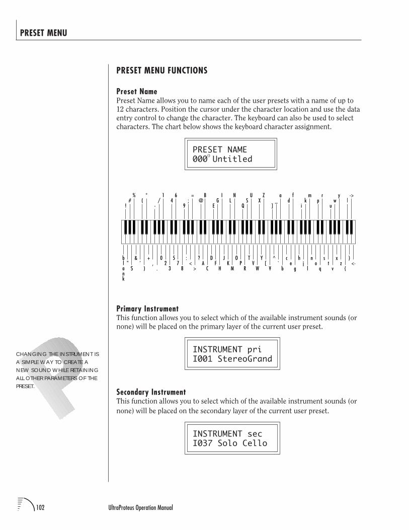
102 UltraProteus Operation Manual
PRESET MENU
PRESET MENU FUNCTIONS
Preset NamePreset Name allows you to name each of the user presets with a name of up to
12 characters. Position the cursor under the character location and use the data
entry control to change the character. The keyboard can also be used to select
characters. The chart below shows the keyboard character assignment.
PRESET NAME000 Untitled
Primary InstrumentThis function allows you to select which of the available instrument sounds (or
none) will be placed on the primary layer of the current user preset.
INSTRUMENT priI001 StereoGrand
Secondary InstrumentThis function allows you to select which of the available instrument sounds (or
none) will be placed on the secondary layer of the current user preset.
INSTRUMENT secI037 Solo Cello
CHANGING THE INSTRUMENT ISA SIMPLE WAY TO CREATE ANEW SOUND WHILE RETAININGALL OTHER PARAMETERS OF THEPRESET.
0
02
3
57
8
:<
>
?A
C
DF
H
JK
M
OP
R
TV
W
Y[
¥
^`
b
ce
g
hj
l
no
q
st
v
xz
<-
+,
.
&'
)
blank
"$
46
9;
=@
B
EG
IL
N
QS
UX
Z
]_
ad
f
ik
mp
r
uw
y|
->
-/
1(
*
!#
%
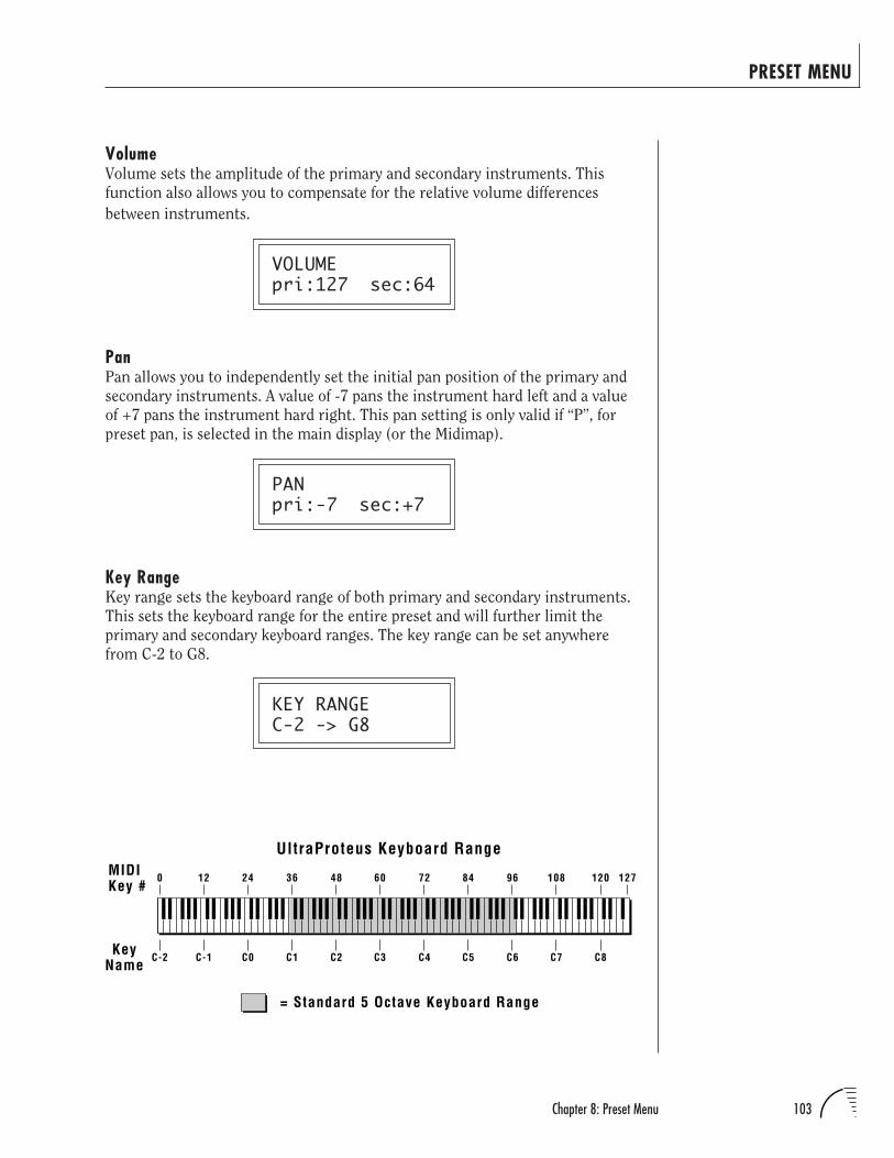
103Chapter 8: Preset Menu
PRESET MENU
VolumeVolume sets the amplitude of the primary and secondary instruments. This
function also allows you to compensate for the relative volume differences
between instruments.
VOLUMEpri:127 sec:64
PanPan allows you to independently set the initial pan position of the primary and
secondary instruments. A value of -7 pans the instrument hard left and a value
of +7 pans the instrument hard right. This pan setting is only valid if “P”, for
preset pan, is selected in the main display (or the Midimap).
PANpri:-7 sec:+7
Key RangeKey range sets the keyboard range of both primary and secondary instruments.
This sets the keyboard range for the entire preset and will further limit the
primary and secondary keyboard ranges. The key range can be set anywhere
from C-2 to G8.
KEY RANGEC-2 -> G8
C-2 C-1 C0 C1 C2 C3 C4 C5 C6 C7 C8
= Standard 5 Octave Keyboard Range
UltraProteus Keyboard RangeMIDIKey #
KeyName
0 12 24 36 48 60 72 84 96 108 120 127
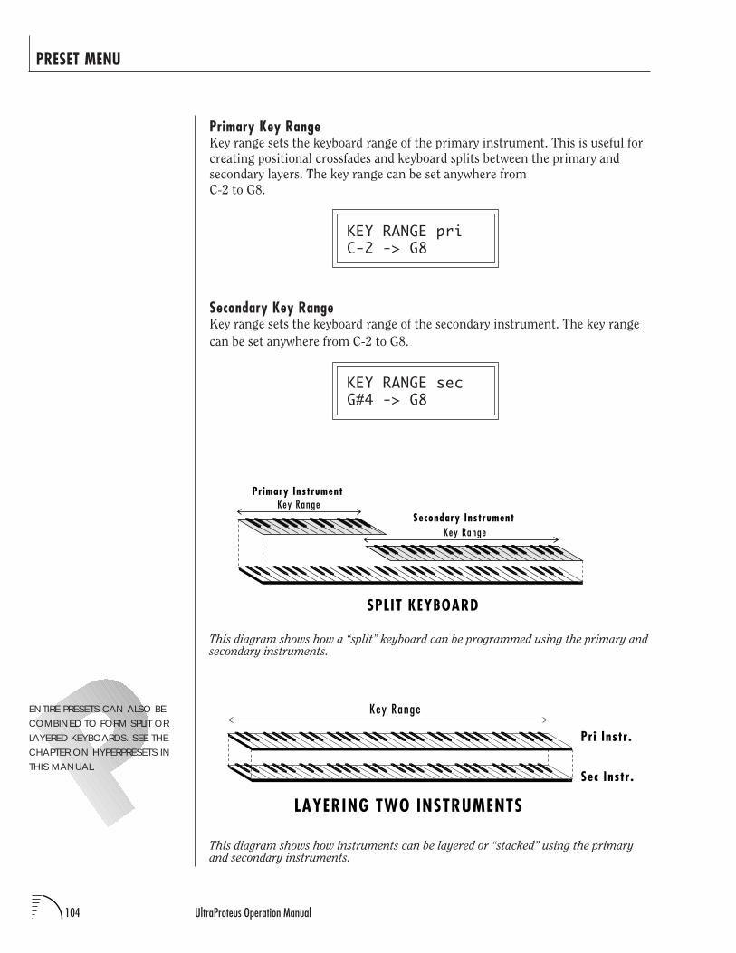
104 UltraProteus Operation Manual
Primary Key RangeKey range sets the keyboard range of the primary instrument. This is useful for
creating positional crossfades and keyboard splits between the primary and
secondary layers. The key range can be set anywhere from
C-2 to G8.
KEY RANGE priC-2 -> G8
Secondary Key RangeKey range sets the keyboard range of the secondary instrument. The key range
can be set anywhere from C-2 to G8.
KEY RANGE secG#4 -> G8
PRESET MENU
This diagram shows how instruments can be layered or “stacked” using the primaryand secondary instruments.
This diagram shows how a “split” keyboard can be programmed using the primary andsecondary instruments.
ENTIRE PRESETS CAN ALSO BECOMBINED TO FORM SPLIT ORLAYERED KEYBOARDS. SEE THECHAPTER ON HYPERPRESETS INTHIS MANUAL.
Pri Instr.
Sec Instr.
LAYERING TWO INSTRUMENTS
Key Range
Primary InstrumentKey Range
Key Range
SPLIT KEYBOARD
Secondary Instrument
105Chapter 8: Preset Menu
PRESET MENU
TransposeThis function allows you to transpose the key of the primary and secondary
instruments in semitone intervals by shifting the keyboard position relative to
middle C. The transpose range is -36 to +36 semitones.
TRANSPOSEpri:+00 sec:+00
Coarse Pitch TuningThis function allows you to change the tuning of the primary and secondary
instruments in semitone intervals. The coarse tuning range is -36 to +36
semitones.
PITCH TUNE crsepri:+00 sec:+00
Fine Pitch TuningThis function allows you to change the tuning of the primary and secondary
instruments in 1/64 semitone intervals (approx. 1.56 cents). The fine tuning
range is ± 1 semitone.
PITCH TUNE finepri:+00 sec:+00
Alternate Volume Envelope On/OffEach instrument has its own factory preset AHDSR volume envelope which is
used if this parameter is set to Off. Turn Alternate Volume Envelope On to use
the user-programmable alternate envelope.
ALT VOL ENVELOPEpri:Off sec:On
USE TRANSPOSE WHEN YOUWANT THE INSTRUMENT'STIMBRE TO REMAIN CONSTANT.
USE COARSE TUNING WHENYOU WANT TO CHANGE THETIMBRE OF THE INSTRUMENT.
USE THE COARSE TUNINGCONTROL TO CHANGE THETUNING OF MULTIPLE DRUMINSTRUMENTS.
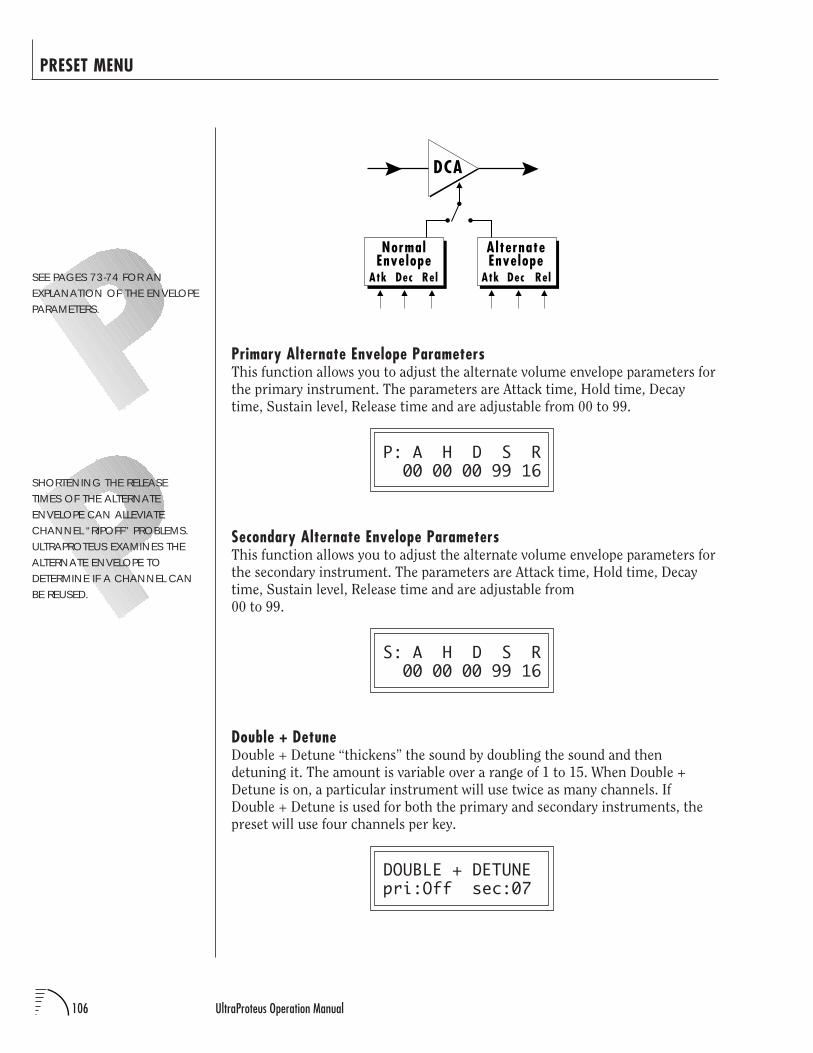
106 UltraProteus Operation Manual
Primary Alternate Envelope ParametersThis function allows you to adjust the alternate volume envelope parameters for
the primary instrument. The parameters are Attack time, Hold time, Decay
time, Sustain level, Release time and are adjustable from 00 to 99.
P: A H D S R 00 00 00 99 16
Secondary Alternate Envelope ParametersThis function allows you to adjust the alternate volume envelope parameters for
the secondary instrument. The parameters are Attack time, Hold time, Decay
time, Sustain level, Release time and are adjustable from
00 to 99.
S: A H D S R 00 00 00 99 16
Double + DetuneDouble + Detune “thickens” the sound by doubling the sound and then
detuning it. The amount is variable over a range of 1 to 15. When Double +
Detune is on, a particular instrument will use twice as many channels. If
Double + Detune is used for both the primary and secondary instruments, the
preset will use four channels per key.
DOUBLE + DETUNEpri:Off sec:07
PRESET MENU
DCA
Atk Dec Rel
NormalEnvelope
Atk Dec Rel
AlternateEnvelope
SEE PAGES 73-74 FOR ANEXPLANATION OF THE ENVELOPEPARAMETERS.
SHORTENING THE RELEASETIMES OF THE ALTERNATEENVELOPE CAN ALLEVIATECHANNEL “RIPOFF” PROBLEMS.ULTRAPROTEUS EXAMINES THEALTERNATE ENVELOPE TODETERMINE IF A CHANNEL CANBE REUSED.
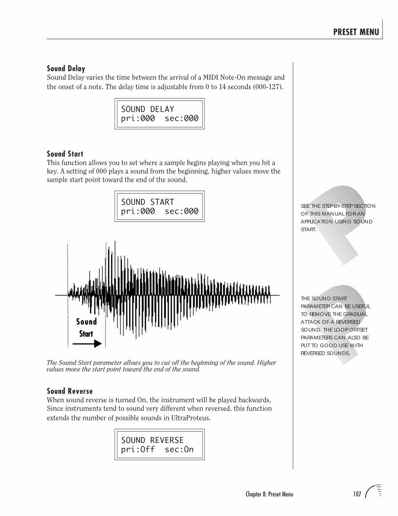
107Chapter 8: Preset Menu
PRESET MENU
Sound DelaySound Delay varies the time between the arrival of a MIDI Note-On message and
the onset of a note. The delay time is adjustable from 0 to 14 seconds (000-127).
SOUND DELAYpri:000 sec:000
Sound StartThis function allows you to set where a sample begins playing when you hit a
key. A setting of 000 plays a sound from the beginning, higher values move the
sample start point toward the end of the sound.
SOUND STARTpri:000 sec:000
The Sound Start parameter allows you to cut off the beginning of the sound. Highervalues move the start point toward the end of the sound.
SEE THE STEP-BY-STEP SECTIONOF THIS MANUAL FOR ANAPPLICATION USING SOUNDSTART.
SoundStart
Sound ReverseWhen sound reverse is turned On, the instrument will be played backwards.
Since instruments tend to sound very different when reversed, this function
extends the number of possible sounds in UltraProteus.
SOUND REVERSEpri:Off sec:On
THE SOUND STARTPARAMETER CAN BE USEFULTO REMOVE THE GRADUALATTACK OF A REVERSEDSOUND. THE LOOP OFFSETPARAMETERS CAN ALSO BEPUT TO GOOD USE WITHREVERSED SOUNDS.
108 UltraProteus Operation Manual
PRESET MENU
NontransposeThis function turns keyboard transposition On or Off for the primary and
secondary instruments. With Nontranspose On, the keyboard will not control
the pitch of the instrument. This is a useful function for drones or “chiffs”,
which you may not want to track the keyboard.
NONTRANSPOSEpri:Off sec:On
Loop EnableThis function allows you to turn the loop in a sound On or Off. Looping is a way
that sounds can be sustained indefinitely. If you want an instrument to play
once, then stop, turn Off the Loop Enable function.
LOOP ENABLEpri:Off sec:On
Loop OffsetAll the UltraProteus instruments have been factory looped for your convenience.
The Loop Offset function allows you to modify the Loop Start Point and the
Loop Size so you can create your own loops.
By looping the sound on the attack portion of an instrument, you can create
new waveforms. The Loop Start and Loop Size parameters can cross sample
boundaries so that more than one instrument will play. Sample boundary
crossing may be useful to create a special effect or background ambience. A
Start and Size Offset of 000,000 returns you to the factory loop setting.
LOOP OFFSET LOOP OFFSETStartP +000,000 SizeP +000,000
LOOP OFFSET LOOP OFFSETStartS +000,000 SizeS +000,000
IN SOME CASES, SUCH ASTHE INDIVIDUAL PERCUSSIONSOUNDS, LOOPING MAYNOT BE DESIRABLE. IF THIS ISTHE CASE, TURN LOOPENABLE OFF.
Primary
Secondary
LOOP OFFSET IDEASLOOP OFFSET CAN BE USED TOCREATE INTERESTING NEWTIMBRES BY LOOPING ON THEATTACK TRANSIENT OF ANINSTRUMENT.
BY TRAVERSING SEVERALINSTRUMENTS YOU MAY FINDINTERESTING POLYRHYTHMS.
EXTREMELY LONG LOOP SIZESCAN CREATE INCREDIBLEBACKGROUND AMBIENCE. USEPITCH-SHIFTING AND MULTIPLEKEYS.
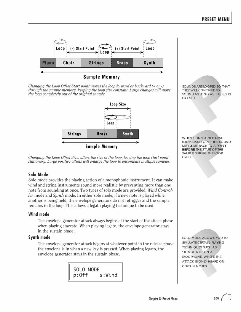
109Chapter 8: Preset Menu
PRESET MENU
Solo ModeSolo mode provides the playing action of a monophonic instrument. It can make
wind and string instruments sound more realistic by preventing more than one
note from sounding at once. Two types of solo mode are provided: Wind Control-
ler mode and Synth mode. In either solo mode, if a new note is played while
another is being held, the envelope generators do not retrigger and the sample
remains in the loop. This allows a legato playing technique to be used.
Wind modeThe envelope generator attack always begins at the start of the attack phase
when playing staccato. When playing legato, the envelope generator stays
in the sustain phase.
Synth modeThe envelope generator attack begins at whatever point in the release phase
the envelope is in when a new key is pressed. When playing legato, the
envelope generator stays in the sustain phase.
SOLO MODEp:Off s:Wind
SOUNDS ARE LOOPED SO THATTHEY WILL CONTINUE TOSOUND AS LONG AS THE KEY ISPRESSED.
Piano Choir Strings Brass Synth
Loop Loop(+) Start PointLoop
Sample Memory
(-) Start Point
Strings
Loop
Loop Size
Brass Synth
Sample Memory
Changing the Loop Offset Start point moves the loop forward or backward (+ or -)through the sample memory, keeping the loop size constant. Large changes will movethe loop completely out of the original sample.
WHEN USING A NEGATIVELOOP START POINT, THE SOUNDMAY JUMP BACK TO A POINTBEFORE THE START OF THESAMPLE DURING THE LOOPCYCLE.Changing the Loop Offset Size, alters the size of the loop, leaving the loop start point
stationary. Large positive offsets will enlarge the loop to encompass multiple samples.
SOLO MODE ALLOWS YOU TOSIMULATE CERTAIN PLAYINGTECHNIQUES SUCH AS“TONGUING” ON ASAXOPHONE, WHERE THEATTACK IS ONLY HEARD ONCERTAIN NOTES.
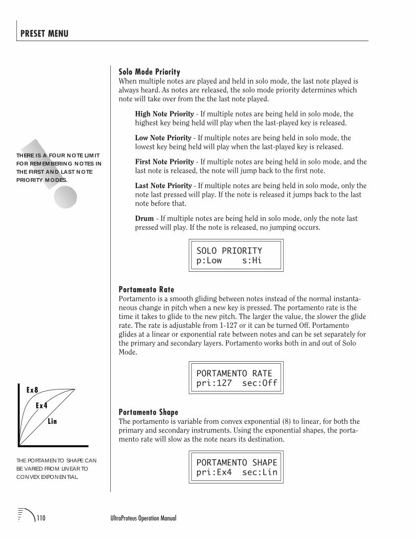
110 UltraProteus Operation Manual
PRESET MENU
Solo Mode PriorityWhen multiple notes are played and held in solo mode, the last note played is
always heard. As notes are released, the solo mode priority determines which
note will take over from the the last note played.
High Note Priority - If multiple notes are being held in solo mode, the
highest key being held will play when the last-played key is released.
Low Note Priority - If multiple notes are being held in solo mode, the
lowest key being held will play when the last-played key is released.
First Note Priority - If multiple notes are being held in solo mode, and the
last note is released, the note will jump back to the first note.
Last Note Priority - If multiple notes are being held in solo mode, only the
note last pressed will play. If the note is released it jumps back to the last
note before that.
Drum - If multiple notes are being held in solo mode, only the note last
pressed will play. If the note is released, no jumping occurs.
SOLO PRIORITYp:Low s:Hi
Portamento RatePortamento is a smooth gliding between notes instead of the normal instanta-
neous change in pitch when a new key is pressed. The portamento rate is the
time it takes to glide to the new pitch. The larger the value, the slower the glide
rate. The rate is adjustable from 1-127 or it can be turned Off. Portamento
glides at a linear or exponential rate between notes and can be set separately for
the primary and secondary layers. Portamento works both in and out of Solo
Mode.
PORTAMENTO RATEpri:127 sec:Off
Portamento ShapeThe portamento is variable from convex exponential (8) to linear, for both the
primary and secondary instruments. Using the exponential shapes, the porta-
mento rate will slow as the note nears its destination.
PORTAMENTO SHAPEpri:Ex4 sec:Lin
THERE IS A FOUR NOTE LIMITFOR REMEMBERING NOTES INTHE FIRST AND LAST NOTEPRIORITY MODES.
THE PORTAMENTO SHAPE CANBE VARIED FROM LINEAR TOCONVEX EXPONENTIAL.
Ex4
Lin
Ex8
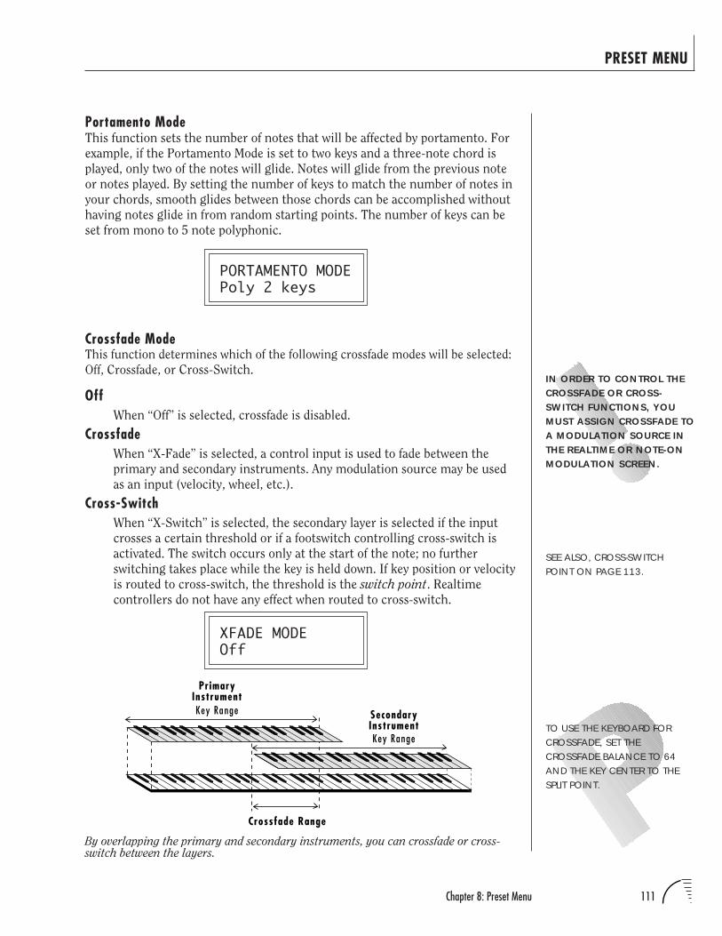
111Chapter 8: Preset Menu
PRESET MENU
IN ORDER TO CONTROL THECROSSFADE OR CROSS-SWITCH FUNCTIONS, YOUMUST ASSIGN CROSSFADE TOA MODULATION SOURCE INTHE REALTIME OR NOTE-ONMODULATION SCREEN.
TO USE THE KEYBOARD FORCROSSFADE, SET THECROSSFADE BALANCE TO 64AND THE KEY CENTER TO THESPLIT POINT.
SEE ALSO, CROSS-SWITCHPOINT ON PAGE 113.
By overlapping the primary and secondary instruments, you can crossfade or cross-switch between the layers.
Portamento ModeThis function sets the number of notes that will be affected by portamento. For
example, if the Portamento Mode is set to two keys and a three-note chord is
played, only two of the notes will glide. Notes will glide from the previous note
or notes played. By setting the number of keys to match the number of notes in
your chords, smooth glides between those chords can be accomplished without
having notes glide in from random starting points. The number of keys can be
set from mono to 5 note polyphonic.
PORTAMENTO MODEPoly 2 keys
Crossfade ModeThis function determines which of the following crossfade modes will be selected:
Off, Crossfade, or Cross-Switch.
OffWhen “Off” is selected, crossfade is disabled.
CrossfadeWhen “X-Fade” is selected, a control input is used to fade between the
primary and secondary instruments. Any modulation source may be used
as an input (velocity, wheel, etc.).
Cross-SwitchWhen “X-Switch” is selected, the secondary layer is selected if the input
crosses a certain threshold or if a footswitch controlling cross-switch is
activated. The switch occurs only at the start of the note; no further
switching takes place while the key is held down. If key position or velocity
is routed to cross-switch, the threshold is the switch point. Realtime
controllers do not have any effect when routed to cross-switch.
XFADE MODEOff
PrimaryInstrumentKey Range
Key Range
SecondaryInstrument
Crossfade Range
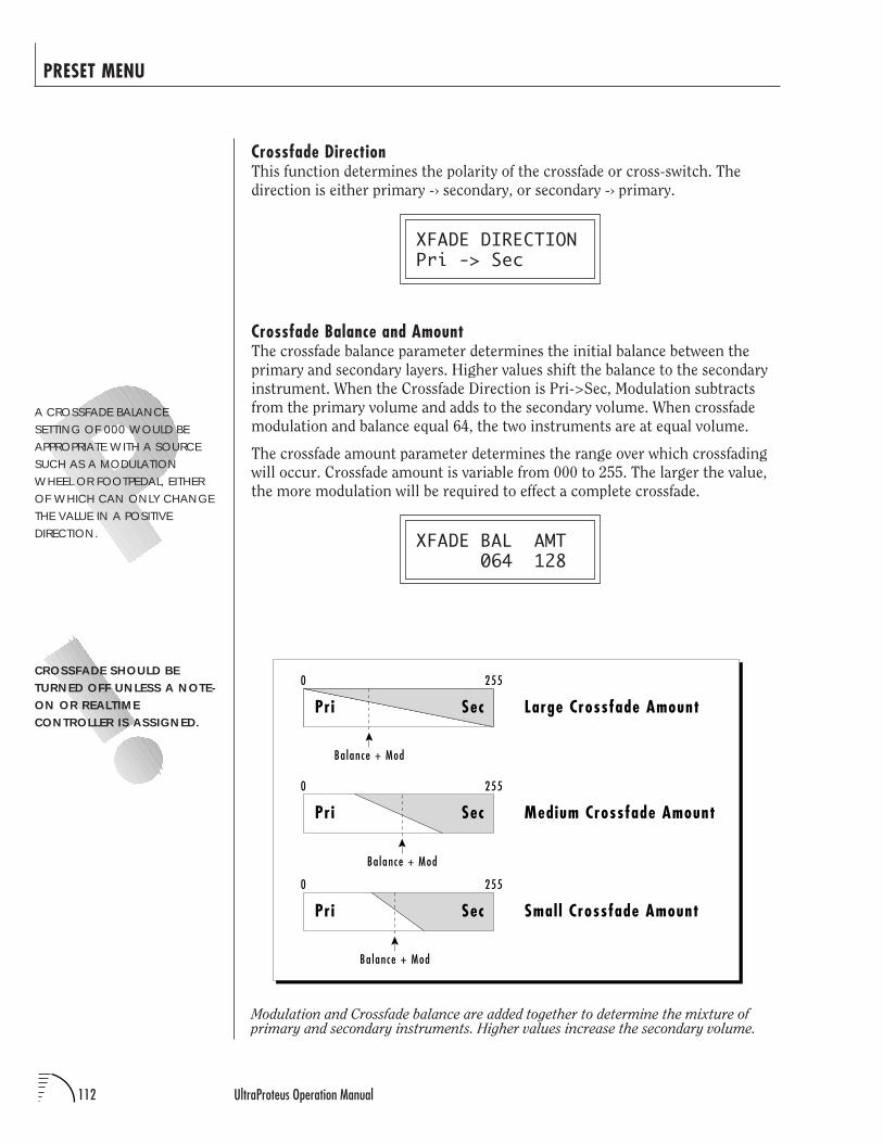
112 UltraProteus Operation Manual
PRESET MENU
A CROSSFADE BALANCESETTING OF 000 WOULD BEAPPROPRIATE WITH A SOURCESUCH AS A MODULATIONWHEEL OR FOOTPEDAL, EITHEROF WHICH CAN ONLY CHANGETHE VALUE IN A POSITIVEDIRECTION.
Crossfade DirectionThis function determines the polarity of the crossfade or cross-switch. The
direction is either primary -› secondary, or secondary -› primary.
XFADE DIRECTIONPri -> Sec
Crossfade Balance and AmountThe crossfade balance parameter determines the initial balance between the
primary and secondary layers. Higher values shift the balance to the secondary
instrument. When the Crossfade Direction is Pri->Sec, Modulation subtracts
from the primary volume and adds to the secondary volume. When crossfade
modulation and balance equal 64, the two instruments are at equal volume.
The crossfade amount parameter determines the range over which crossfading
will occur. Crossfade amount is variable from 000 to 255. The larger the value,
the more modulation will be required to effect a complete crossfade.
XFADE BAL AMT 064 128
Modulation and Crossfade balance are added together to determine the mixture ofprimary and secondary instruments. Higher values increase the secondary volume.
CROSSFADE SHOULD BETURNED OFF UNLESS A NOTE-ON OR REALTIMECONTROLLER IS ASSIGNED.
0 255
Pri Sec Medium Crossfade Amount
0 255
Pri Sec
0 255
Pri Sec
Balance + Mod
Balance + Mod
Balance + Mod
Large Crossfade Amount
Small Crossfade Amount
113Chapter 8: Preset Menu
Cross-Switch PointThe Cross-Switch point determines the point at which cross-switching will
occur when key position or velocity is controlling Cross-Switch.
XSWITCH POINT064 (E3)
Primary Filter TypeThis screen allows you to select one of 288 Z-Plane filter types available in ROM.
These filters include: traditional low-pass filters, flanger simulators, vowel
formants, distortion filters, acoustic instrument models and many, many more.
See the reference section for a complete listing and descriptions of the filters.
FILTER TYPE priF035 Ee-Yi.4
Secondary Filter TypeThis screen allows you to set the filter type for the secondary layer. See Primary
Filter Type.
FILTER TYPE secF269 TensionWire
Filter LevelThis function sets the amount of signal into the filter. This control can be used
to balance the levels between instruments or to control the distortion charac-
teristics of the filter. Depending on the type of instrument and the filter, this
control can have a dramatic effect on the sound. This control differs from the
Volume parameter which adjusts the volume after the filter. The default setting
is 255 (full level).
FILTER LEVELpri:198 sec:255
IN ORDER TO CONTROL THECROSS-SWITCH FUNCTION,YOU MUST ASSIGNCROSSFADE TO AMODULATION SOURCE INTHE NOTE-ON OR REALTIMECONTROL SCREENS.
PRESET MENU
UNDER CERTAIN UNUSUALCIRCUMSTANCES THE FILTERSMAY OVERLOAD,PRODUCING A LOUDOBJECTIONABLE NOISE.TURN DOWN THE FILTERLEVEL VALUE TO ALLEVIATETHE PROBLEM.
Velocity Key
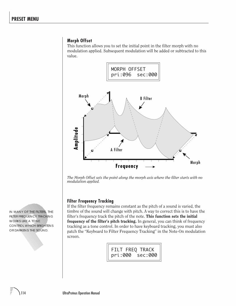
114 UltraProteus Operation Manual
PRESET MENU
Morph OffsetThis function allows you to set the initial point in the filter morph with no
modulation applied. Subsequent modulation will be added or subtracted to this
value.
MORPH OFFSETpri:096 sec:000
The Morph Offset sets the point along the morph axis where the filter starts with nomodulation applied.
Filter Frequency TrackingIf the filter frequency remains constant as the pitch of a sound is varied, the
timbre of the sound will change with pitch. A way to correct this is to have the
filter's frequency track the pitch of the note. This function sets the initial
frequency of the filter's pitch tracking. In general, you can think of frequency
tracking as a tone control. In order to have keyboard tracking, you must also
patch the “Keyboard to Filter Frequency Tracking” in the Note-On modulation
screen.
FILT FREQ TRACKpri:000 sec:000
IN MANY OF THE FILTERS, THEFILTER FREQUENCY TRACKINGWORKS LIKE A TONECONTROL WHICH BRIGHTENSOR DARKENS THE SOUND.
Frequency
Ampl
itud
e
Morph
A F i l ter
B F i l ter
Morph
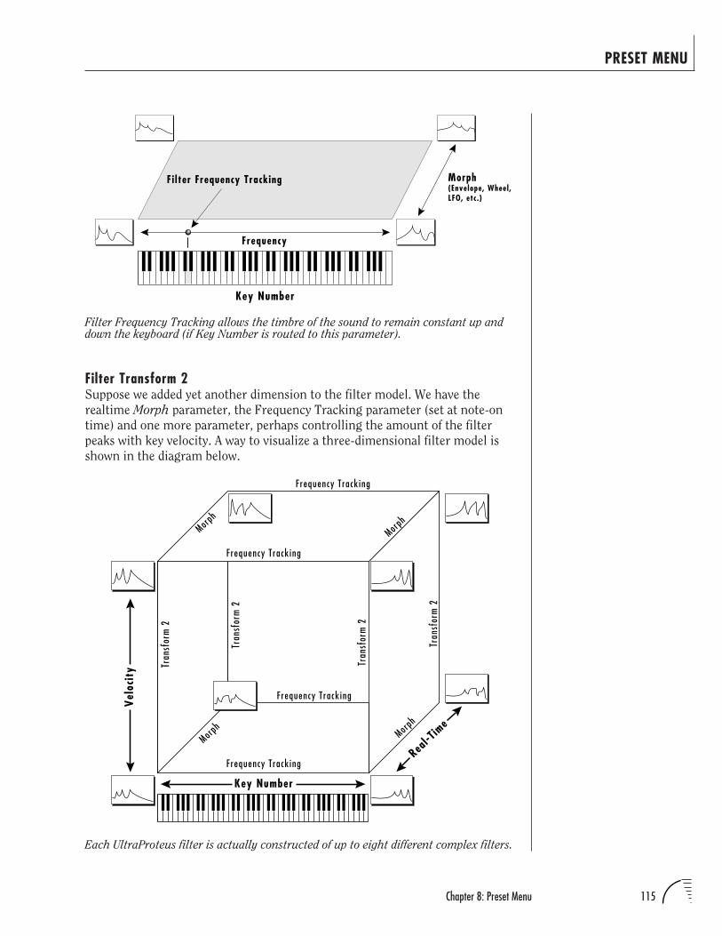
115Chapter 8: Preset Menu
PRESET MENU
Filter Frequency Tracking allows the timbre of the sound to remain constant up anddown the keyboard (if Key Number is routed to this parameter).
Each UltraProteus filter is actually constructed of up to eight different complex filters.
Filter Transform 2Suppose we added yet another dimension to the filter model. We have the
realtime Morph parameter, the Frequency Tracking parameter (set at note-on
time) and one more parameter, perhaps controlling the amount of the filter
peaks with key velocity. A way to visualize a three-dimensional filter model is
shown in the diagram below.
Key Number
Morph(Envelope, Wheel,LFO, etc.)
F i lter Frequency Tracking
Frequency
Key Number
Frequency Track ing
Tran
sfor
m 2
Vel
ocit
y
Morph
Morph
Tran
sfor
m 2
Tran
sfor
m 2
Morph
Tran
sfor
m 2
Real-T
ime
Morph
Frequency Track ing
Frequency Track ing
Frequency Track ing
116 UltraProteus Operation Manual
Each axis of the three-dimensional cube changes the filter in a different way. In
the example above, key number is being applied to the Frequency Tracking
parameter in order to make the filter frequency track or follow the notes played
on the keyboard.
In the 3-D filter model, there is another note-on (defined at the time the note is
pressed) parameter, Transform 2. Unlike the frequency tracking parameter, the
effect of Transform 2 varies from filter to filter. In the example above, Trans-
form 2 is being used to vary the size of the peaks and notches in the filter. The
frequency plots in the upper plane of the cube have sharper peaks. In the
example above, key velocity is being used to control Transform 2 and the
sharpness of the filter peaks.
Filter Transform 2 sets the Initial Point along the Transform 2 axis. Subsequent
modulation (from note-on modulation) adds to this initial setting for the
primary and secondary filters.
FILT TRANSFORM 2pri:000 sec:127
Filter ReverseThis function allows you to reverse the direction of all of the filter controls. Key
Tracking, Transform 2 and the Morph parameters will all operate in reverse.
The Offset points are reversed, as well as the direction of filter modulation.
FILTER REVERSEpri:Off sec:Off
Auxiliary EnvelopeThis is a supplementary, utility envelope that can be routed to any realtime
control destination including the Morph filter. The auxiliary envelope param-
eters are: Envelope Amount, Delay, Attack Time, Hold Time, Decay Time,
Sustain Level, and Release Time. The delay time is variable from 0 to 13 seconds
(000-127). The envelope amount is variable from -128 to +127. Negative values
will produce inverted envelopes.
AUX ENV AMT DLY A: A H D S R +127 000 00 00 00 99 20
PRESET MENU
FOR MORE INFORMATION ONTHE ENVELOPES, SEE THE PRESETPROGRAMMING SECTION OFTHIS MANUAL.
MANY OF THE FILTERS INULTRAPROTEUS DO NOT USETRANSFORM 2.
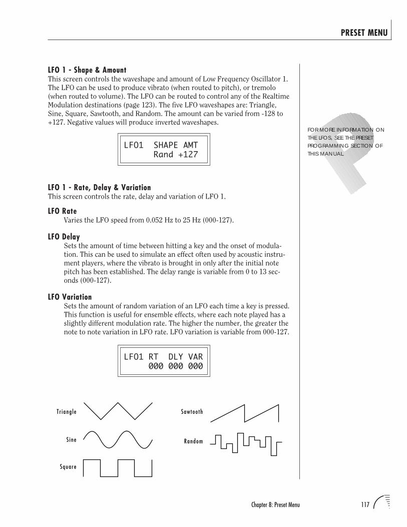
117Chapter 8: Preset Menu
LFO 1 - Shape & AmountThis screen controls the waveshape and amount of Low Frequency Oscillator 1.
The LFO can be used to produce vibrato (when routed to pitch), or tremolo
(when routed to volume). The LFO can be routed to control any of the Realtime
Modulation destinations (page 123). The five LFO waveshapes are: Triangle,
Sine, Square, Sawtooth, and Random. The amount can be varied from -128 to
+127. Negative values will produce inverted waveshapes.
LFO1 SHAPE AMT Rand +127
LFO 1 - Rate, Delay & VariationThis screen controls the rate, delay and variation of LFO 1.
LFO RateVaries the LFO speed from 0.052 Hz to 25 Hz (000-127).
LFO DelaySets the amount of time between hitting a key and the onset of modula-
tion. This can be used to simulate an effect often used by acoustic instru-
ment players, where the vibrato is brought in only after the initial note
pitch has been established. The delay range is variable from 0 to 13 sec-
onds (000-127).
LFO VariationSets the amount of random variation of an LFO each time a key is pressed.
This function is useful for ensemble effects, where each note played has a
slightly different modulation rate. The higher the number, the greater the
note to note variation in LFO rate. LFO variation is variable from 000-127.
LFO1 RT DLY VAR 000 000 000
PRESET MENU
FOR MORE INFORMATION ONTHE LFOS, SEE THE PRESETPROGRAMMING SECTION OFTHIS MANUAL.
T r i ang l e
Squa re
S i ne
Saw too th
Random
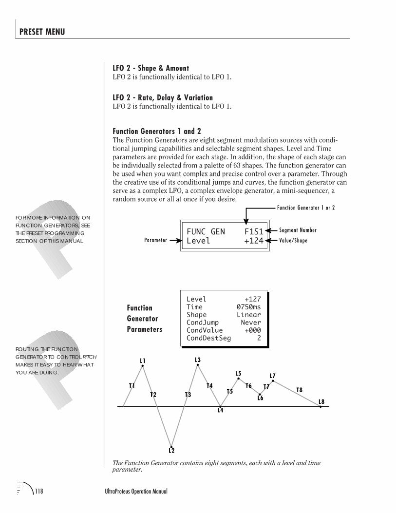
118 UltraProteus Operation Manual
PRESET MENU
The Function Generator contains eight segments, each with a level and timeparameter.
FOR MORE INFORMATION ONFUNCTION GENERATORS, SEETHE PRESET PROGRAMMINGSECTION OF THIS MANUAL.
LFO 2 - Shape & AmountLFO 2 is functionally identical to LFO 1.
LFO 2 - Rate, Delay & VariationLFO 2 is functionally identical to LFO 1.
Function Generators 1 and 2The Function Generators are eight segment modulation sources with condi-
tional jumping capabilities and selectable segment shapes. Level and Time
parameters are provided for each stage. In addition, the shape of each stage can
be individually selected from a palette of 63 shapes. The function generator can
be used when you want complex and precise control over a parameter. Through
the creative use of its conditional jumps and curves, the function generator can
serve as a complex LFO, a complex envelope generator, a mini-sequencer, a
random source or all at once if you desire.
FUNC GEN F1S1Level +124
Level +127Time 0750msShape LinearCondJump NeverCondValue +000CondDestSeg 2
FunctionGeneratorParameters
ROUTING THE FUNCTIONGENERATOR TO CONTROL PITCHMAKES IT EASY TO HEAR WHATYOU ARE DOING.
L1
T1
L2
L3
L4
L5
L6
L7
L8T2 T3
T4T5
T6 T7 T8
Segment Number
Parameter Value/Shape
Funct ion Generator 1 or 2
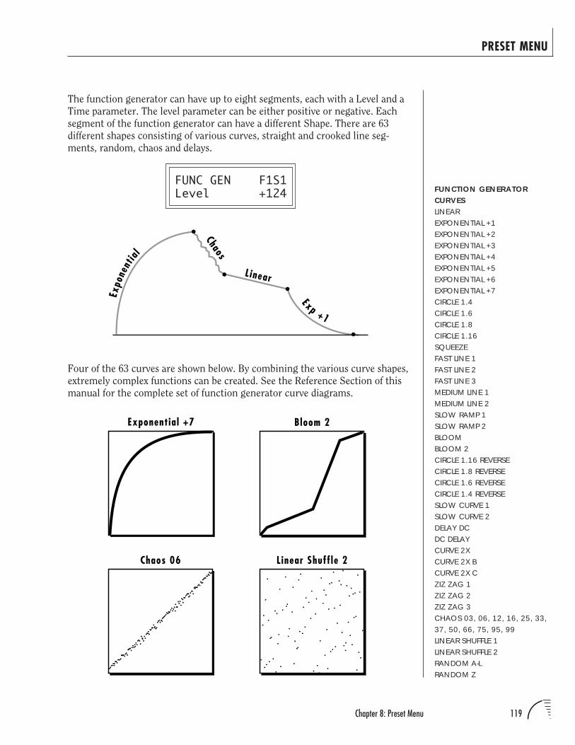
119Chapter 8: Preset Menu
PRESET MENU
The function generator can have up to eight segments, each with a Level and a
Time parameter. The level parameter can be either positive or negative. Each
segment of the function generator can have a different Shape. There are 63
different shapes consisting of various curves, straight and crooked line seg-
ments, random, chaos and delays.
FUNC GEN F1S1Level +124
Four of the 63 curves are shown below. By combining the various curve shapes,
extremely complex functions can be created. See the Reference Section of this
manual for the complete set of function generator curve diagrams.
FUNCTION GENERATORCURVESLINEAREXPONENTIAL +1EXPONENTIAL +2EXPONENTIAL +3EXPONENTIAL +4EXPONENTIAL +5EXPONENTIAL +6EXPONENTIAL +7CIRCLE 1.4CIRCLE 1.6CIRCLE 1.8CIRCLE 1.16SQUEEZEFAST LINE 1FAST LINE 2FAST LINE 3MEDIUM LINE 1MEDIUM LINE 2SLOW RAMP 1SLOW RAMP 2BLOOMBLOOM 2CIRCLE 1.16 REVERSECIRCLE 1.8 REVERSECIRCLE 1.6 REVERSECIRCLE 1.4 REVERSESLOW CURVE 1SLOW CURVE 2DELAY DCDC DELAYCURVE 2XCURVE 2X BCURVE 2X CZIZ ZAG 1ZIZ ZAG 2ZIZ ZAG 3CHAOS 03, 06, 12, 16, 25, 33,37, 50, 66, 75, 95, 99LINEAR SHUFFLE 1LINEAR SHUFFLE 2RANDOM A-LRANDOM Z
Chaos
L inear
Expo
nent
ial
Exp +1
Exponential +7 Bloom 2
Chaos 06 Linear Shuffle 2
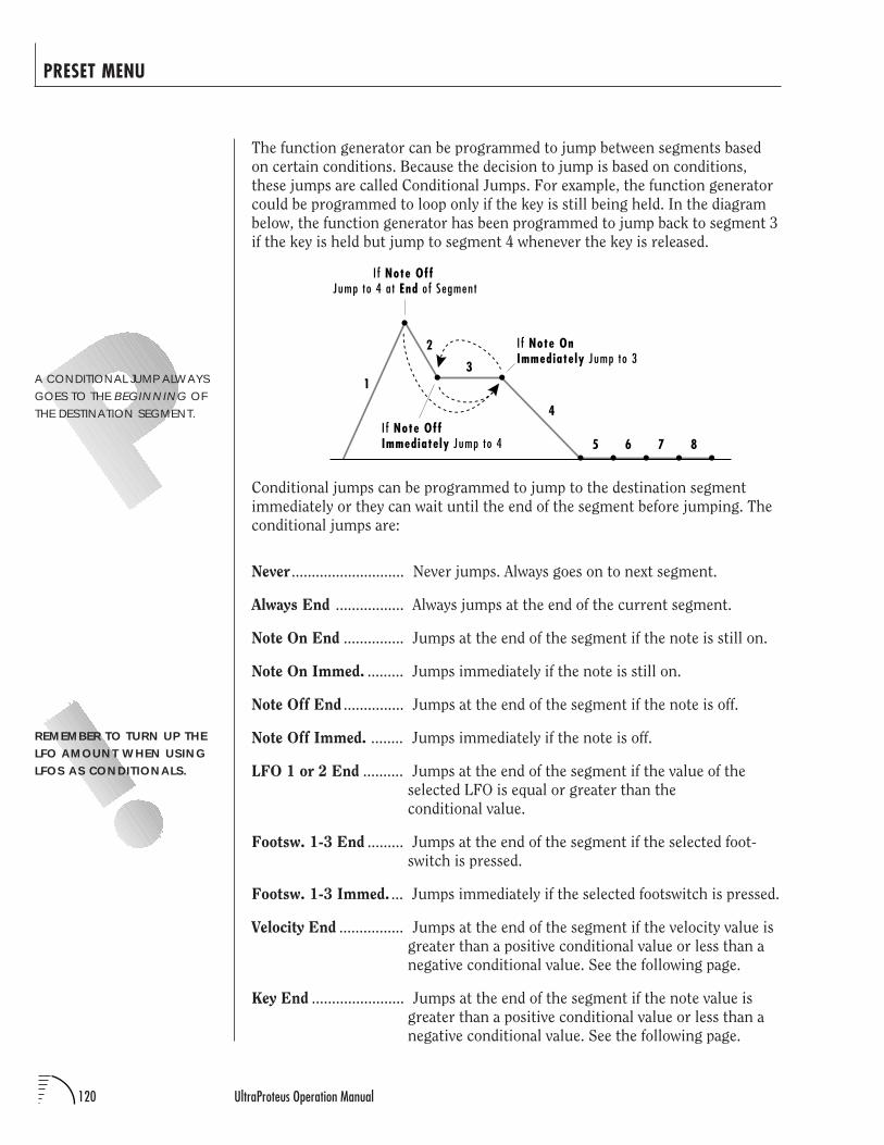
120 UltraProteus Operation Manual
PRESET MENU
The function generator can be programmed to jump between segments based
on certain conditions. Because the decision to jump is based on conditions,
these jumps are called Conditional Jumps. For example, the function generator
could be programmed to loop only if the key is still being held. In the diagram
below, the function generator has been programmed to jump back to segment 3
if the key is held but jump to segment 4 whenever the key is released.
REMEMBER TO TURN UP THELFO AMOUNT WHEN USINGLFOS AS CONDITIONALS.
A CONDITIONAL JUMP ALWAYSGOES TO THE BEGINNING OFTHE DESTINATION SEGMENT.
Conditional jumps can be programmed to jump to the destination segment
immediately or they can wait until the end of the segment before jumping. The
conditional jumps are:
Never ............................ Never jumps. Always goes on to next segment.
Always End ................. Always jumps at the end of the current segment.
Note On End ............... Jumps at the end of the segment if the note is still on.
Note On Immed. ......... Jumps immediately if the note is still on.
Note Off End ............... Jumps at the end of the segment if the note is off.
Note Off Immed. ........ Jumps immediately if the note is off.
LFO 1 or 2 End .......... Jumps at the end of the segment if the value of the
selected LFO is equal or greater than the
conditional value.
Footsw. 1-3 End ......... Jumps at the end of the segment if the selected foot-
switch is pressed.
Footsw. 1-3 Immed. ... Jumps immediately if the selected footswitch is pressed.
Velocity End ................ Jumps at the end of the segment if the velocity value is
greater than a positive conditional value or less than a
negative conditional value. See the following page.
Key End ....................... Jumps at the end of the segment if the note value is
greater than a positive conditional value or less than a
negative conditional value. See the following page.
1
2
3
4
I f Note Off Jump to 4 at End of Segment
5 6 7 8I f Note OffImmediately Jump to 4
I f Note OnImmediately Jump to 3
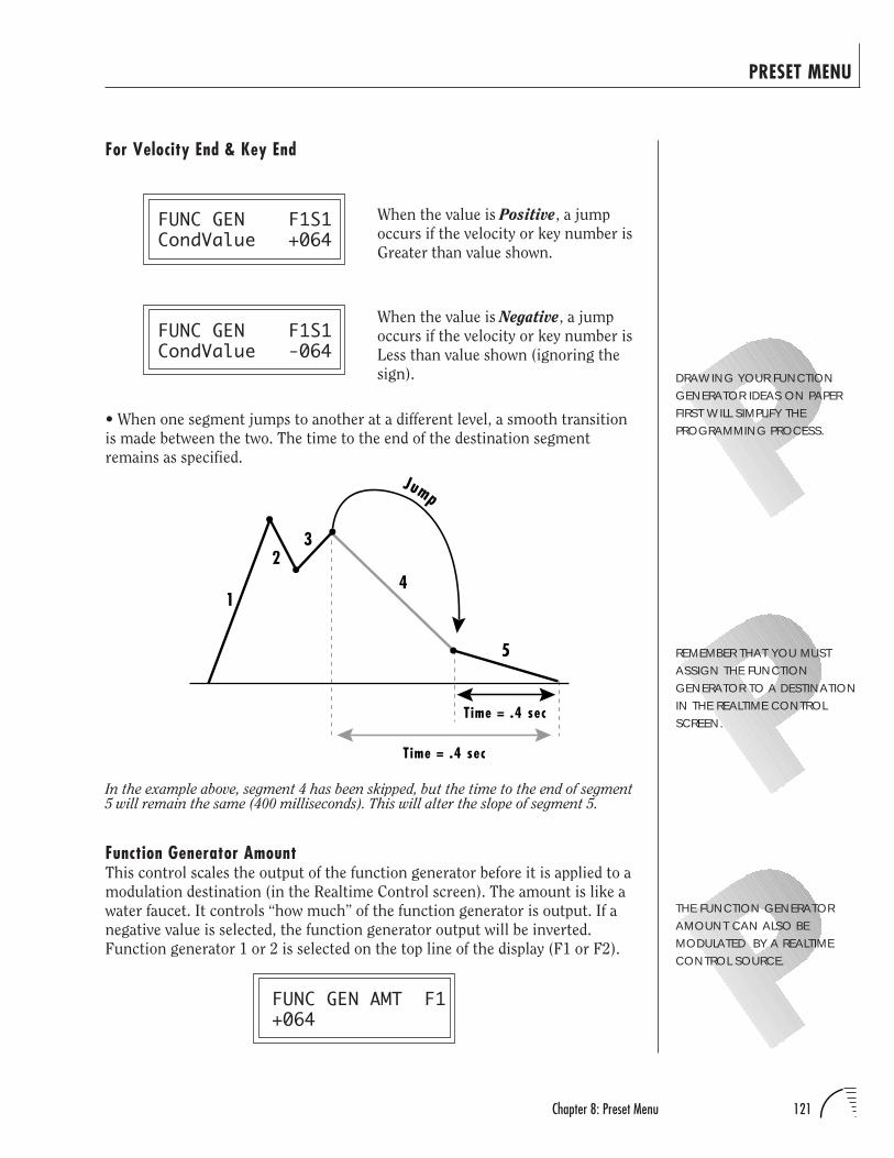
121Chapter 8: Preset Menu
PRESET MENU
For Velocity End & Key End
FUNC GEN F1S1CondValue +064
FUNC GEN F1S1CondValue -064
• When one segment jumps to another at a different level, a smooth transition
is made between the two. The time to the end of the destination segment
remains as specified.
When the value is Negative, a jump
occurs if the velocity or key number is
Less than value shown (ignoring the
sign).
When the value is Positive, a jump
occurs if the velocity or key number is
Greater than value shown.
Function Generator AmountThis control scales the output of the function generator before it is applied to a
modulation destination (in the Realtime Control screen). The amount is like a
water faucet. It controls “how much” of the function generator is output. If a
negative value is selected, the function generator output will be inverted.
Function generator 1 or 2 is selected on the top line of the display (F1 or F2).
FUNC GEN AMT F1+064
1
23
4
5
Time = .4 sec
Jump
Time = .4 sec
In the example above, segment 4 has been skipped, but the time to the end of segment5 will remain the same (400 milliseconds). This will alter the slope of segment 5.
THE FUNCTION GENERATORAMOUNT CAN ALSO BEMODULATED BY A REALTIMECONTROL SOURCE.
DRAWING YOUR FUNCTIONGENERATOR IDEAS ON PAPERFIRST WILL SIMPLIFY THEPROGRAMMING PROCESS.
REMEMBER THAT YOU MUSTASSIGN THE FUNCTIONGENERATOR TO A DESTINATIONIN THE REALTIME CONTROLSCREEN.
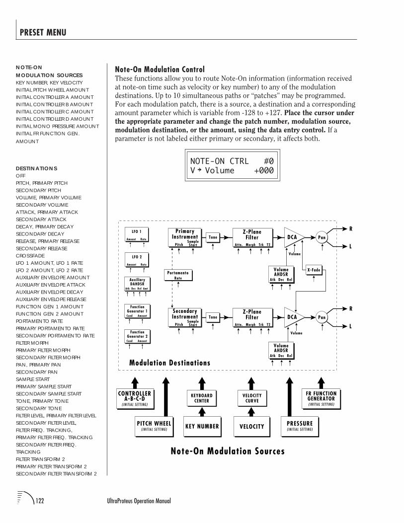
122 UltraProteus Operation Manual
PRESET MENU
Note-On Modulation ControlThese functions allow you to route Note-On information (information received
at note-on time such as velocity or key number) to any of the modulation
destinations. Up to 10 simultaneous paths or “patches” may be programmed.
For each modulation patch, there is a source, a destination and a corresponding
amount parameter which is variable from -128 to +127. Place the cursor under
the appropriate parameter and change the patch number, modulation source,
modulation destination, or the amount, using the data entry control. If a
parameter is not labeled either primary or secondary, it affects both.
NOTE-ON CTRL #0V Volume +000
NOTE-ONMODULATION SOURCESKEY NUMBER, KEY VELOCITYINITIAL PITCH WHEEL AMOUNTINITIAL CONTROLLER A AMOUNTINITIAL CONTROLLER B AMOUNTINITIAL CONTROLLER C AMOUNTINITIAL CONTROLLER D AMOUNTINITIAL MONO PRESSURE AMOUNTINITIAL FR FUNCTION GEN.AMOUNT
DESTINATIONSOFFPITCH, PRIMARY PITCHSECONDARY PITCHVOLUME, PRIMARY VOLUMESECONDARY VOLUMEATTACK, PRIMARY ATTACKSECONDARY ATTACKDECAY, PRIMARY DECAYSECONDARY DECAYRELEASE, PRIMARY RELEASESECONDARY RELEASECROSSFADELFO 1 AMOUNT, LFO 1 RATELFO 2 AMOUNT, LFO 2 RATEAUXILIARY ENVELOPE AMOUNTAUXILIARY ENVELOPE ATTACKAUXILIARY ENVELOPE DECAYAUXILIARY ENVELOPE RELEASEFUNCTION GEN 1 AMOUNTFUNCTION GEN 2 AMOUNTPORTAMENTO RATEPRIMARY PORTAMENTO RATESECONDARY PORTAMENTO RATEFILTER MORPHPRIMARY FILTER MORPHSECONDARY FILTER MORPHPAN, PRIMARY PANSECONDARY PANSAMPLE STARTPRIMARY SAMPLE STARTSECONDARY SAMPLE STARTTONE, PRIMARY TONESECONDARY TONEFILTER LEVEL, PRIMARY FILTER LEVELSECONDARY FILTER LEVEL,FILTER FREQ. TRACKING,PRIMARY FILTER FREQ. TRACKINGSECONDARY FILTER FREQ.TRACKINGFILTER TRANSFORM 2PRIMARY FILTER TRANSFORM 2SECONDARY FILTER TRANSFORM 2
LFO 1
Amount Rate
LFO 2
Amount Rate
R
LVolume
PanPrimary
InstrumentPitch
SampleStart
Tone
VELOCITY
VELOCITYCURVE
KEY NUMBER
KEYBOARDCENTER
Note-On Modulation Sources
X-Fade
Atk Dec Rel
VolumeAHDSR
R
LVolume
PanSecondaryInstrument
PitchSampleStart
Tone
Atk Dec Rel
VolumeAHDSR
PortamentoRate
DCA
DCA
Modulation Destinations
Auxil iaryDAHDSR
AmtAtk Dec Rel
CONTROLLERA-B-C-D
( INIT IAL SETTING)
PRESSURE( INIT IAL SETTING)
FR FUNCTIONGENERATOR( INIT IAL SETTING)
PITCH WHEEL( INIT IAL SETTING)
FunctionGenerator 1
AmountCond
FunctionGenerator 2
AmountCond
Z-PlaneFi lter
T2TrkMorphAttn.
Z-PlaneFi lter
T2TrkMorphAttn.
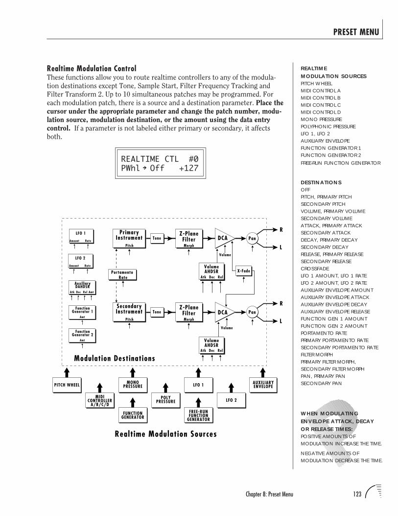
123Chapter 8: Preset Menu
PRESET MENU
Realtime Modulation ControlThese functions allow you to route realtime controllers to any of the modula-
tion destinations except Tone, Sample Start, Filter Frequency Tracking and
Filter Transform 2. Up to 10 simultaneous patches may be programmed. For
each modulation patch, there is a source and a destination parameter. Place the
cursor under the appropriate parameter and change the patch number, modu-
lation source, modulation destination, or the amount using the data entry
control. If a parameter is not labeled either primary or secondary, it affects
both.
REALTIME CTL #0PWhl Off +127
WHEN MODULATINGENVELOPE ATTACK, DECAYOR RELEASE TIMES:POSITIVE AMOUNTS OFMODULATION INCREASE THE TIME.
NEGATIVE AMOUNTS OFMODULATION DECREASE THE TIME.
REALTIMEMODULATION SOURCESPITCH WHEELMIDI CONTROL AMIDI CONTROL BMIDI CONTROL CMIDI CONTROL DMONO PRESSUREPOLYPHONIC PRESSURELFO 1, LFO 2AUXILIARY ENVELOPEFUNCTION GENERATOR 1FUNCTION GENERATOR 2FREE-RUN FUNCTION GENERATOR
DESTINATIONSOFFPITCH, PRIMARY PITCHSECONDARY PITCHVOLUME, PRIMARY VOLUMESECONDARY VOLUMEATTACK, PRIMARY ATTACKSECONDARY ATTACKDECAY, PRIMARY DECAYSECONDARY DECAYRELEASE, PRIMARY RELEASESECONDARY RELEASECROSSFADELFO 1 AMOUNT, LFO 1 RATELFO 2 AMOUNT, LFO 2 RATEAUXILIARY ENVELOPE AMOUNTAUXILIARY ENVELOPE ATTACKAUXILIARY ENVELOPE DECAYAUXILIARY ENVELOPE RELEASEFUNCTION GEN 1 AMOUNTFUNCTION GEN 2 AMOUNTPORTAMENTO RATEPRIMARY PORTAMENTO RATESECONDARY PORTAMENTO RATEFILTER MORPHPRIMARY FILTER MORPH,SECONDARY FILTER MORPHPAN, PRIMARY PANSECONDARY PAN
Realt ime Modulation Sources
POLYPRESSURE
MONOPRESSURE
MIDICONTROLLER
A/B/C/DLFO 2
AUXILIARYENVELOPELFO 1PITCH WHEEL
Auxil iaryDAHDSR
AmtAtk Dec Rel
LFO 1
Amount Rate
LFO 2
Amount Rate
Modulation Destinations
R
LVolume
Pan
Atk Dec Rel
VolumeAHDSR
PrimaryInstrument
Pitch
ToneZ-Plane
Fi lter
X-Fade
R
LVolume
Pan
Atk Dec Rel
VolumeAHDSR
SecondaryInstrument
Pitch
ToneZ-Plane
Fi lter
Morph
Morph
PortamentoRate
DCA
DCA
FUNCTIONGENERATOR
FREE-RUNFUNCTION
GENERATOR
FunctionGenerator 1
Amt
FunctionGenerator 2
Amt
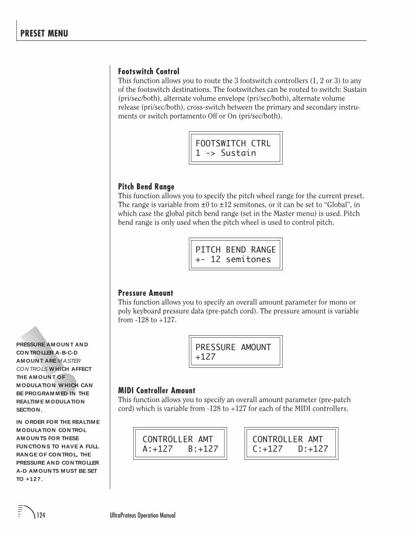
124 UltraProteus Operation Manual
PRESET MENU
Footswitch ControlThis function allows you to route the 3 footswitch controllers (1, 2 or 3) to any
of the footswitch destinations. The footswitches can be routed to switch: Sustain
(pri/sec/both), alternate volume envelope (pri/sec/both), alternate volume
release (pri/sec/both), cross-switch between the primary and secondary instru-
ments or switch portamento Off or On (pri/sec/both).
FOOTSWITCH CTRL1 -> Sustain
Pitch Bend RangeThis function allows you to specify the pitch wheel range for the current preset.
The range is variable from ±0 to ±12 semitones, or it can be set to “Global”, in
which case the global pitch bend range (set in the Master menu) is used. Pitch
bend range is only used when the pitch wheel is used to control pitch.
PITCH BEND RANGE+- 12 semitones
Pressure AmountThis function allows you to specify an overall amount parameter for mono or
poly keyboard pressure data (pre-patch cord). The pressure amount is variable
from -128 to +127.
PRESSURE AMOUNT+127
MIDI Controller AmountThis function allows you to specify an overall amount parameter (pre-patch
cord) which is variable from -128 to +127 for each of the MIDI controllers.
CONTROLLER AMT CONTROLLER AMTA:+127 B:+127 C:+127 D:+127
PRESSURE AMOUNT ANDCONTROLLER A-B-C-DAMOUNT ARE MASTERCONTROLS WHICH AFFECTTHE AMOUNT OFMODULATION WHICH CANBE PROGRAMMED IN THEREALTIME MODULATIONSECTION.
IN ORDER FOR THE REALTIMEMODULATION CONTROLAMOUNTS FOR THESEFUNCTIONS TO HAVE A FULLRANGE OF CONTROL, THEPRESSURE AND CONTROLLERA-D AMOUNTS MUST BE SETTO +127.
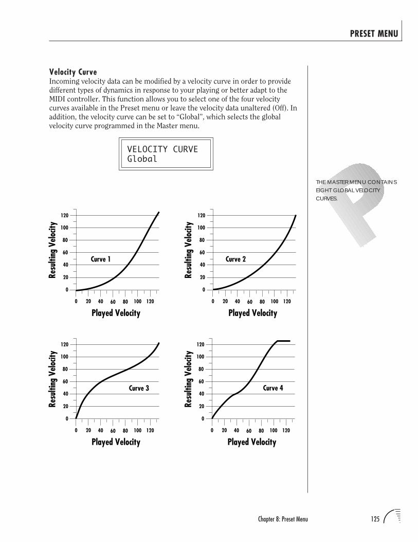
125Chapter 8: Preset Menu
PRESET MENU
Velocity CurveIncoming velocity data can be modified by a velocity curve in order to provide
different types of dynamics in response to your playing or better adapt to the
MIDI controller. This function allows you to select one of the four velocity
curves available in the Preset menu or leave the velocity data unaltered (Off). In
addition, the velocity curve can be set to “Global”, which selects the global
velocity curve programmed in the Master menu.
VELOCITY CURVEGlobal
Curve 1
0
20
40
60
80
100
120
0 20 40 60 80 100
Played Velocity120
Resu
lting
Velo
city
Curve 2
0
20
40
60
80
100
120
0 20 40 60 80 100
Played Velocity120
Resu
lting
Velo
city
Curve 3
0
20
40
60
80
100
120
0 20 40 60 80 100
Played Velocity120
Resu
lting
Velo
city
0
20
40
60
80
100
120
0 20 40 60 80 100
Played Velocity120
Resu
lting
Velo
city
Curve 4
THE MASTER MENU CONTAINSEIGHT GLOBAL VELOCITYCURVES.
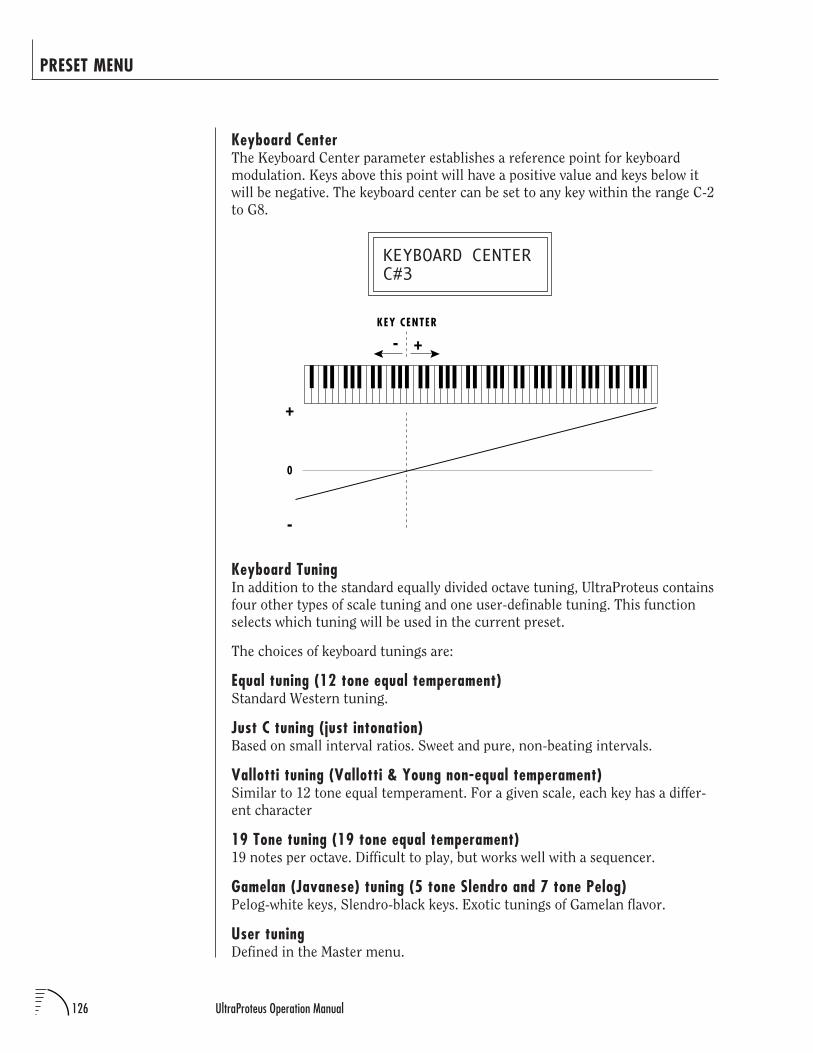
126 UltraProteus Operation Manual
PRESET MENU
Keyboard CenterThe Keyboard Center parameter establishes a reference point for keyboard
modulation. Keys above this point will have a positive value and keys below it
will be negative. The keyboard center can be set to any key within the range C-2
to G8.
KEYBOARD CENTERC#3
Keyboard TuningIn addition to the standard equally divided octave tuning, UltraProteus contains
four other types of scale tuning and one user-definable tuning. This function
selects which tuning will be used in the current preset.
The choices of keyboard tunings are:
Equal tuning (12 tone equal temperament)Standard Western tuning.
Just C tuning (just intonation)Based on small interval ratios. Sweet and pure, non-beating intervals.
Vallotti tuning (Vallotti & Young non-equal temperament)Similar to 12 tone equal temperament. For a given scale, each key has a differ-
ent character
19 Tone tuning (19 tone equal temperament)19 notes per octave. Difficult to play, but works well with a sequencer.
Gamelan (Javanese) tuning (5 tone Slendro and 7 tone Pelog)Pelog-white keys, Slendro-black keys. Exotic tunings of Gamelan flavor.
User tuningDefined in the Master menu.
KEY CENTER
+
-
0
-
+
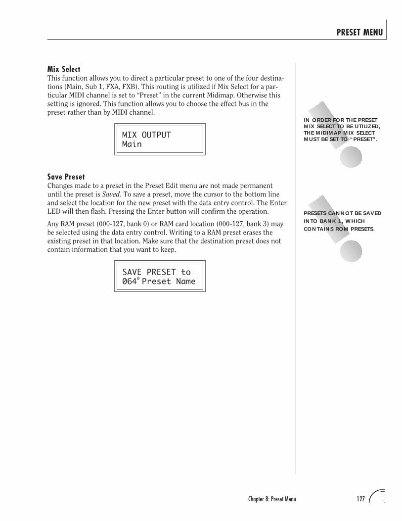
127Chapter 8: Preset Menu
PRESET MENU
Mix SelectThis function allows you to direct a particular preset to one of the four destina-
tions (Main, Sub 1, FXA, FXB). This routing is utilized if Mix Select for a par-
ticular MIDI channel is set to “Preset” in the current Midimap. Otherwise this
setting is ignored. This function allows you to choose the effect bus in the
preset rather than by MIDI channel.
MIX OUTPUTMain
Save PresetChanges made to a preset in the Preset Edit menu are not made permanent
until the preset is Saved. To save a preset, move the cursor to the bottom line
and select the location for the new preset with the data entry control. The Enter
LED will then flash. Pressing the Enter button will confirm the operation.
Any RAM preset (000-127, bank 0) or RAM card location (000-127, bank 3) may
be selected using the data entry control. Writing to a RAM preset erases the
existing preset in that location. Make sure that the destination preset does not
contain information that you want to keep.
SAVE PRESET to064 Preset Name
IN ORDER FOR THE PRESETMIX SELECT TO BE UTILIZED,THE MIDIMAP MIX SELECTMUST BE SET TO “PRESET”.
0
PRESETS CANNOT BE SAVEDINTO BANK 1, WHICHCONTAINS ROM PRESETS.

128 UltraProteus Operation Manual

129Chapter 9: Copy Menu
COPY MENU
UltraProteus COPY MENU

130 UltraProteus Operation Manual
COPY MENU
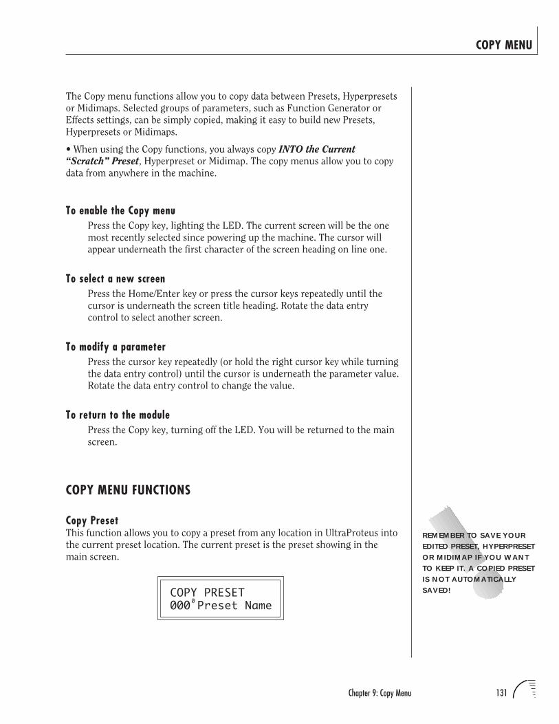
131Chapter 9: Copy Menu
COPY MENU
The Copy menu functions allow you to copy data between Presets, Hyperpresets
or Midimaps. Selected groups of parameters, such as Function Generator or
Effects settings, can be simply copied, making it easy to build new Presets,
Hyperpresets or Midimaps.
• When using the Copy functions, you always copy INTO the Current
“Scratch” Preset, Hyperpreset or Midimap. The copy menus allow you to copy
data from anywhere in the machine.
To enable the Copy menuPress the Copy key, lighting the LED. The current screen will be the one
most recently selected since powering up the machine. The cursor will
appear underneath the first character of the screen heading on line one.
To select a new screenPress the Home/Enter key or press the cursor keys repeatedly until the
cursor is underneath the screen title heading. Rotate the data entry
control to select another screen.
To modify a parameterPress the cursor key repeatedly (or hold the right cursor key while turning
the data entry control) until the cursor is underneath the parameter value.
Rotate the data entry control to change the value.
To return to the modulePress the Copy key, turning off the LED. You will be returned to the main
screen.
COPY MENU FUNCTIONS
Copy PresetThis function allows you to copy a preset from any location in UltraProteus into
the current preset location. The current preset is the preset showing in the
main screen.
COPY PRESET000 Preset Name
REMEMBER TO SAVE YOUREDITED PRESET, HYPERPRESETOR MIDIMAP IF YOU WANTTO KEEP IT. A COPIED PRESETIS NOT AUTOMATICALLYSAVED!
0
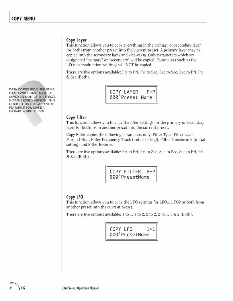
132 UltraProteus Operation Manual
COPY MENU
Copy LayerThis function allows you to copy everything in the primary or secondary layer
(or both) from another preset into the current preset. A primary layer may be
copied into the secondary layer and vice-versa. Only parameters which are
designated “primary” or “secondary” will be copied. Parameters such as the
LFOs or modulation routings will NOT be copied.
There are five options available: Pri to Pri, Pri to Sec, Sec to Sec, Sec to Pri, Pri
& Sec (Both).
COPY LAYER P P000 Preset Name
Copy FilterThis function allows you to copy the filter settings for the primary or secondary
layer (or both) from another preset into the current preset.
Copy Filter copies the following parameters only: Filter Type, Filter Level,
Morph Offset, Filter Frequency Track (initial setting), Filter Transform 2 (initial
setting) and Filter Reverse.
There are five options available: Pri to Pri, Pri to Sec, Sec to Sec, Sec to Pri, Pri
& Sec (Both).
COPY FILTER P P000 PresetName
Copy LFOThis function allows you to copy the LFO settings for LFO1, LFO2 or both from
another preset into the current preset.
There are five options available: 1 to 1, 1 to 2, 2 to 2, 2 to 1, 1 & 2 (Both).
COPY LFO 1 1000 PresetName
DATA COPIED FROM THE SAMEPRESET WILL COME FROM THESAVED VERSION OF THE PRESET,NOT THE EDITED VERSION. THISCOULD BE USED AS A “REVERT”FEATURE IF YOU MAKE AMISTAKE WHILE EDITING.
0
0
0
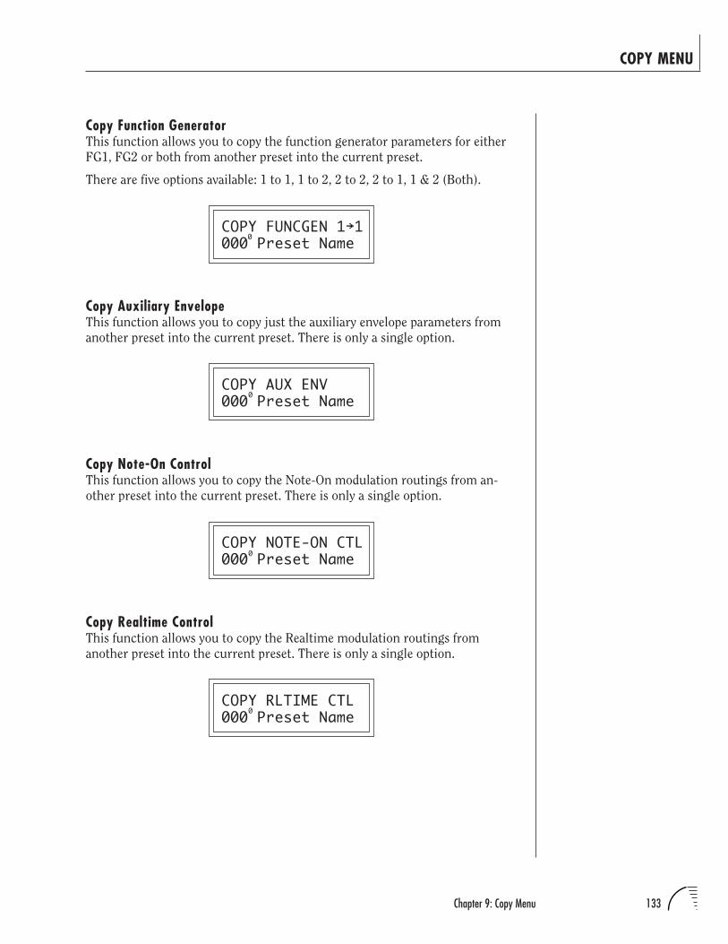
133Chapter 9: Copy Menu
COPY MENU
Copy Function GeneratorThis function allows you to copy the function generator parameters for either
FG1, FG2 or both from another preset into the current preset.
There are five options available: 1 to 1, 1 to 2, 2 to 2, 2 to 1, 1 & 2 (Both).
COPY FUNCGEN 1 1000 Preset Name
Copy Auxiliary EnvelopeThis function allows you to copy just the auxiliary envelope parameters from
another preset into the current preset. There is only a single option.
COPY AUX ENV000 Preset Name
Copy Note-On ControlThis function allows you to copy the Note-On modulation routings from an-
other preset into the current preset. There is only a single option.
COPY NOTE-ON CTL000 Preset Name
Copy Realtime ControlThis function allows you to copy the Realtime modulation routings from
another preset into the current preset. There is only a single option.
COPY RLTIME CTL000 Preset Name
0
0
0
0
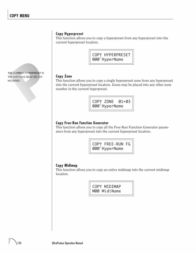
134 UltraProteus Operation Manual
COPY MENU
Copy HyperpresetThis function allows you to copy a hyperpreset from any hyperpreset into the
current hyperpreset location.
COPY HYPERPRESET000 HyperName
Copy ZoneThis function allows you to copy a single hyperpreset zone from any hyperpreset
into the current hyperpreset location. Zones may be placed into any other zone
number in the current hyperpreset.
COPY ZONE 01 03000 HyperName
Copy Free-Run Function GeneratorThis function allows you to copy all the Free-Run Function Generator param-
eters from any hyperpreset into the current hyperpreset location.
COPY FREE-RUN FG000 HyperName
Copy MidimapThis function allows you to copy an entire midimap into the current midimap
location.
COPY MIDIMAPM00 MidiName
THE CURRENT HYPERPRESET ISTHE LAST ONE SELECTED ORMODIFIED.
2
2
2
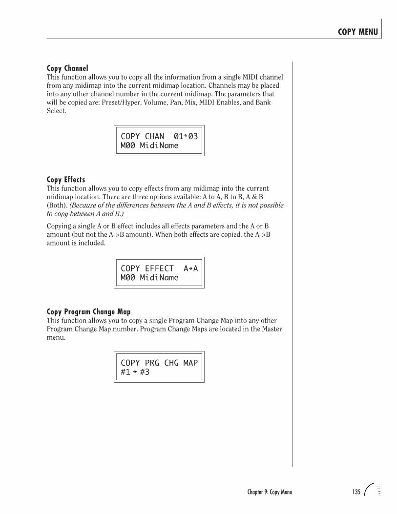
135Chapter 9: Copy Menu
COPY MENU
Copy ChannelThis function allows you to copy all the information from a single MIDI channel
from any midimap into the current midimap location. Channels may be placed
into any other channel number in the current midimap. The parameters that
will be copied are: Preset/Hyper, Volume, Pan, Mix, MIDI Enables, and Bank
Select.
COPY CHAN 01 03M00 MidiName
Copy EffectsThis function allows you to copy effects from any midimap into the current
midimap location. There are three options available: A to A, B to B, A & B
(Both). (Because of the differences between the A and B effects, it is not possible
to copy between A and B.)
Copying a single A or B effect includes all effects parameters and the A or B
amount (but not the A->B amount). When both effects are copied, the A->B
amount is included.
COPY EFFECT A AM00 MidiName
Copy Program Change MapThis function allows you to copy a single Program Change Map into any other
Program Change Map number. Program Change Maps are located in the Master
menu.
COPY PRG CHG MAP#1 #3
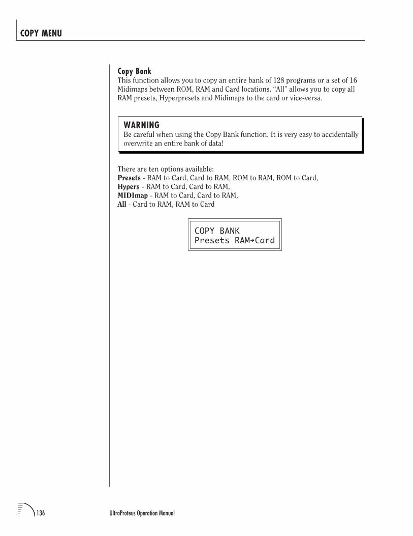
136 UltraProteus Operation Manual
COPY MENU
Copy BankThis function allows you to copy an entire bank of 128 programs or a set of 16
Midimaps between ROM, RAM and Card locations. “All” allows you to copy all
RAM presets, Hyperpresets and Midimaps to the card or vice-versa.
WARNINGBe careful when using the Copy Bank function. It is very easy to accidentally
overwrite an entire bank of data!
There are ten options available:
Presets - RAM to Card, Card to RAM, ROM to RAM, ROM to Card,
Hypers - RAM to Card, Card to RAM,
MIDImap - RAM to Card, Card to RAM,
All - Card to RAM, RAM to Card
COPY BANKPresets RAM Card

137Chapter 10: Step-by-Step
STEP-BY-STEP
UltraProteus STEP-BY-STEP

138 UltraProteus Operation Manual
STEP-BY-STEP
139Chapter 10: Step-by-Step
STEP-BY-STEP
This chapter walks you through UltraProteus in a step-by-step manner. Al-
though it is not possible to cover every detail of programming a synthesizer of
this complexity, these first steps will hopefully get you started in the right
direction. Before starting this chapter, please read the Programming Basics
chapter of this manual. It contains important background information, which
will help you get the most of this chapter.
• If you are new to synthesizers and electronic music, you may need more
background information than this manual provides. There are many books
dedicated to synthesizer basics and MIDI available through your local music
dealer. Magazines such as Keyboard and Electronic Musician, which are avail-
able at most newsstands, contain current information on the subject, as well as
valuable programming tips.
UltraProteus (or any synthesizer for that matter) is not really one instrument
but a collection of modules which can be connected together to create many
different instruments. In programming a synthesizer, you become an instru-
ment builder. The more knowledge you have about music, acoustics, and
electronics, the more success you will have in constructing the sounds of your
dreams.
Learning about sound synthesis will be much easier if you learn to really
LISTEN to the sounds all around you, then try to recreate them. Listen to how
the pitch rises on that bird's chirp, or how the volume changes on that organ.
Soon you'll be hearing sounds in a whole new way. Of course, imitating natural
sounds is only a part of sound synthesis. The real fun happens when you create
a wonderful new sound that no one has ever heard before. Experimentation +
Knowledge = MAGIC!
When playing and programming UltraProteus, you're exploring new territory.
You have to explore to find what's out there! This powerful new technology is
just waiting to be tapped.
EDITING PRESETSA good way to get acquainted with UltraProteus is by examining and editing
existing presets. If you hear an effect or a control you like, take the time to
discover how it was achieved.
Start with a preset you like and try changing it around. If you don't like the
result, simply change the preset momentarily and you'll be back to the original
sound. Changes are not made permanent until you SAVE a preset. Therefore
you can experiment all you want without worrying about losing a sound.
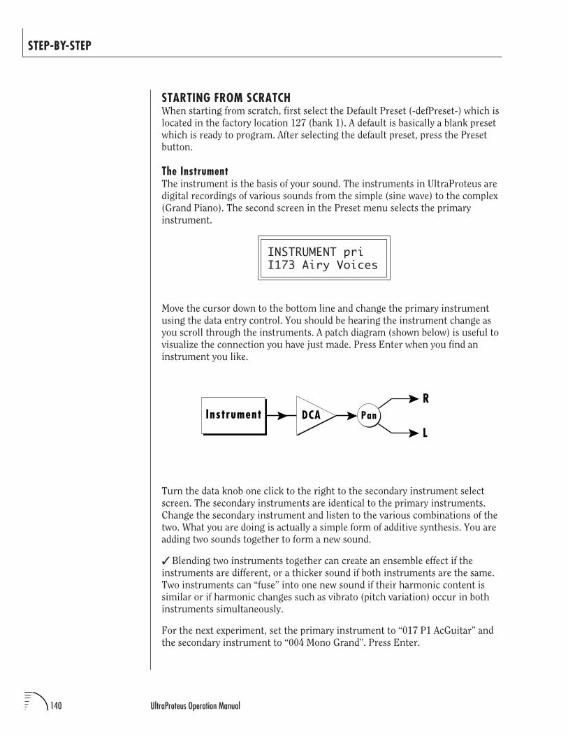
140 UltraProteus Operation Manual
STEP-BY-STEP
STARTING FROM SCRATCHWhen starting from scratch, first select the Default Preset (-defPreset-) which is
located in the factory location 127 (bank 1). A default is basically a blank preset
which is ready to program. After selecting the default preset, press the Preset
button.
The InstrumentThe instrument is the basis of your sound. The instruments in UltraProteus are
digital recordings of various sounds from the simple (sine wave) to the complex
(Grand Piano). The second screen in the Preset menu selects the primary
instrument.
INSTRUMENT priI173 Airy Voices
Move the cursor down to the bottom line and change the primary instrument
using the data entry control. You should be hearing the instrument change as
you scroll through the instruments. A patch diagram (shown below) is useful to
visualize the connection you have just made. Press Enter when you find an
instrument you like.
Turn the data knob one click to the right to the secondary instrument select
screen. The secondary instruments are identical to the primary instruments.
Change the secondary instrument and listen to the various combinations of the
two. What you are doing is actually a simple form of additive synthesis. You are
adding two sounds together to form a new sound.
Blending two instruments together can create an ensemble effect if the
instruments are different, or a thicker sound if both instruments are the same.
Two instruments can “fuse” into one new sound if their harmonic content is
similar or if harmonic changes such as vibrato (pitch variation) occur in both
instruments simultaneously.
For the next experiment, set the primary instrument to “017 P1 AcGuitar” and
the secondary instrument to “004 Mono Grand”. Press Enter.
R
LPanInstrument DCA
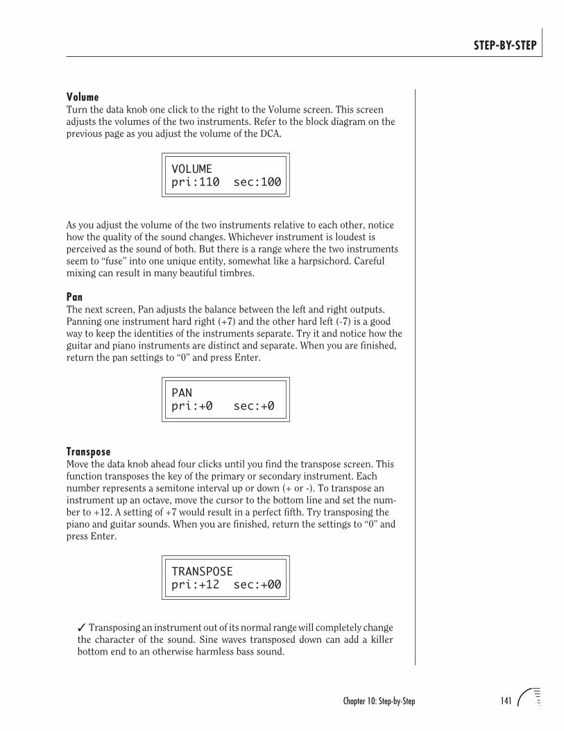
141Chapter 10: Step-by-Step
STEP-BY-STEP
VolumeTurn the data knob one click to the right to the Volume screen. This screen
adjusts the volumes of the two instruments. Refer to the block diagram on the
previous page as you adjust the volume of the DCA.
VOLUMEpri:110 sec:100
As you adjust the volume of the two instruments relative to each other, notice
how the quality of the sound changes. Whichever instrument is loudest is
perceived as the sound of both. But there is a range where the two instruments
seem to “fuse” into one unique entity, somewhat like a harpsichord. Careful
mixing can result in many beautiful timbres.
PanThe next screen, Pan adjusts the balance between the left and right outputs.
Panning one instrument hard right (+7) and the other hard left (-7) is a good
way to keep the identities of the instruments separate. Try it and notice how the
guitar and piano instruments are distinct and separate. When you are finished,
return the pan settings to “0” and press Enter.
PANpri:+0 sec:+0
TransposeMove the data knob ahead four clicks until you find the transpose screen. This
function transposes the key of the primary or secondary instrument. Each
number represents a semitone interval up or down (+ or -). To transpose an
instrument up an octave, move the cursor to the bottom line and set the num-
ber to +12. A setting of +7 would result in a perfect fifth. Try transposing the
piano and guitar sounds. When you are finished, return the settings to “0” and
press Enter.
TRANSPOSEpri:+12 sec:+00
Transposing an instrument out of its normal range will completely change
the character of the sound. Sine waves transposed down can add a killer
bottom end to an otherwise harmless bass sound.
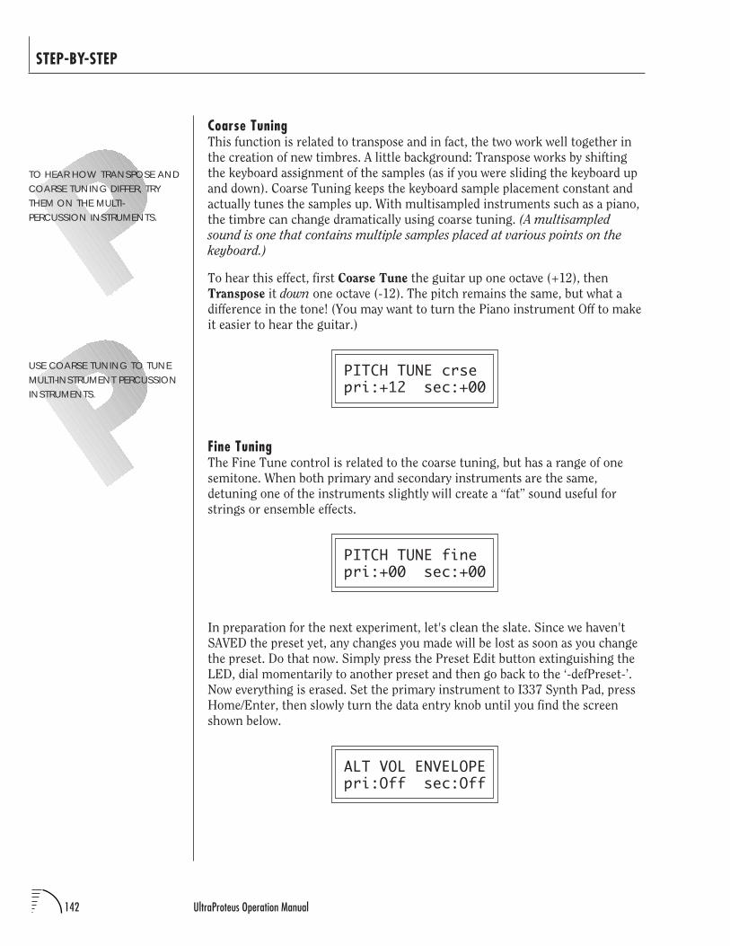
142 UltraProteus Operation Manual
STEP-BY-STEP
Coarse TuningThis function is related to transpose and in fact, the two work well together in
the creation of new timbres. A little background: Transpose works by shifting
the keyboard assignment of the samples (as if you were sliding the keyboard up
and down). Coarse Tuning keeps the keyboard sample placement constant and
actually tunes the samples up. With multisampled instruments such as a piano,
the timbre can change dramatically using coarse tuning. (A multisampled
sound is one that contains multiple samples placed at various points on the
keyboard.)
To hear this effect, first Coarse Tune the guitar up one octave (+12), then
Transpose it down one octave (-12). The pitch remains the same, but what a
difference in the tone! (You may want to turn the Piano instrument Off to make
it easier to hear the guitar.)
PITCH TUNE crsepri:+12 sec:+00
Fine TuningThe Fine Tune control is related to the coarse tuning, but has a range of one
semitone. When both primary and secondary instruments are the same,
detuning one of the instruments slightly will create a “fat” sound useful for
strings or ensemble effects.
PITCH TUNE finepri:+00 sec:+00
In preparation for the next experiment, let's clean the slate. Since we haven't
SAVED the preset yet, any changes you made will be lost as soon as you change
the preset. Do that now. Simply press the Preset Edit button extinguishing the
LED, dial momentarily to another preset and then go back to the ‘-defPreset-’.
Now everything is erased. Set the primary instrument to I337 Synth Pad, press
Home/Enter, then slowly turn the data entry knob until you find the screen
shown below.
ALT VOL ENVELOPEpri:Off sec:Off
TO HEAR HOW TRANSPOSE ANDCOARSE TUNING DIFFER, TRYTHEM ON THE MULTI-PERCUSSION INSTRUMENTS.
USE COARSE TUNING TO TUNEMULTI-INSTRUMENT PERCUSSIONINSTRUMENTS.
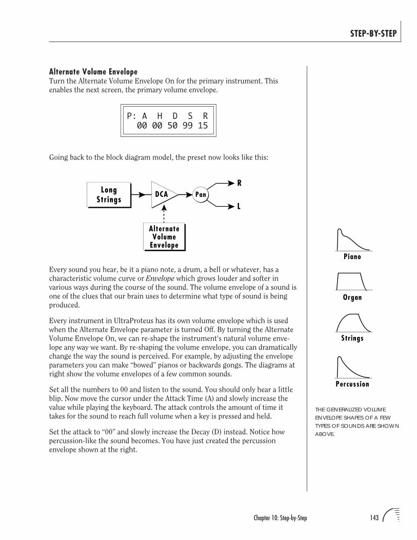
143Chapter 10: Step-by-Step
STEP-BY-STEP
Alternate Volume EnvelopeTurn the Alternate Volume Envelope On for the primary instrument. This
enables the next screen, the primary volume envelope.
P: A H D S R 00 00 50 99 15
Going back to the block diagram model, the preset now looks like this:
THE GENERALIZED VOLUMEENVELOPE SHAPES OF A FEWTYPES OF SOUNDS ARE SHOWNABOVE.
Every sound you hear, be it a piano note, a drum, a bell or whatever, has a
characteristic volume curve or Envelope which grows louder and softer in
various ways during the course of the sound. The volume envelope of a sound is
one of the clues that our brain uses to determine what type of sound is being
produced.
Every instrument in UltraProteus has its own volume envelope which is used
when the Alternate Envelope parameter is turned Off. By turning the Alternate
Volume Envelope On, we can re-shape the instrument's natural volume enve-
lope any way we want. By re-shaping the volume envelope, you can dramatically
change the way the sound is perceived. For example, by adjusting the envelope
parameters you can make “bowed” pianos or backwards gongs. The diagrams at
right show the volume envelopes of a few common sounds.
Set all the numbers to 00 and listen to the sound. You should only hear a little
blip. Now move the cursor under the Attack Time (A) and slowly increase the
value while playing the keyboard. The attack controls the amount of time it
takes for the sound to reach full volume when a key is pressed and held.
Set the attack to “00” and slowly increase the Decay (D) instead. Notice how
percussion-like the sound becomes. You have just created the percussion
envelope shown at the right.
Percussion
Piano
Organ
Strings
R
LPanLong
StringsDCA
AlternateVolume
Envelope
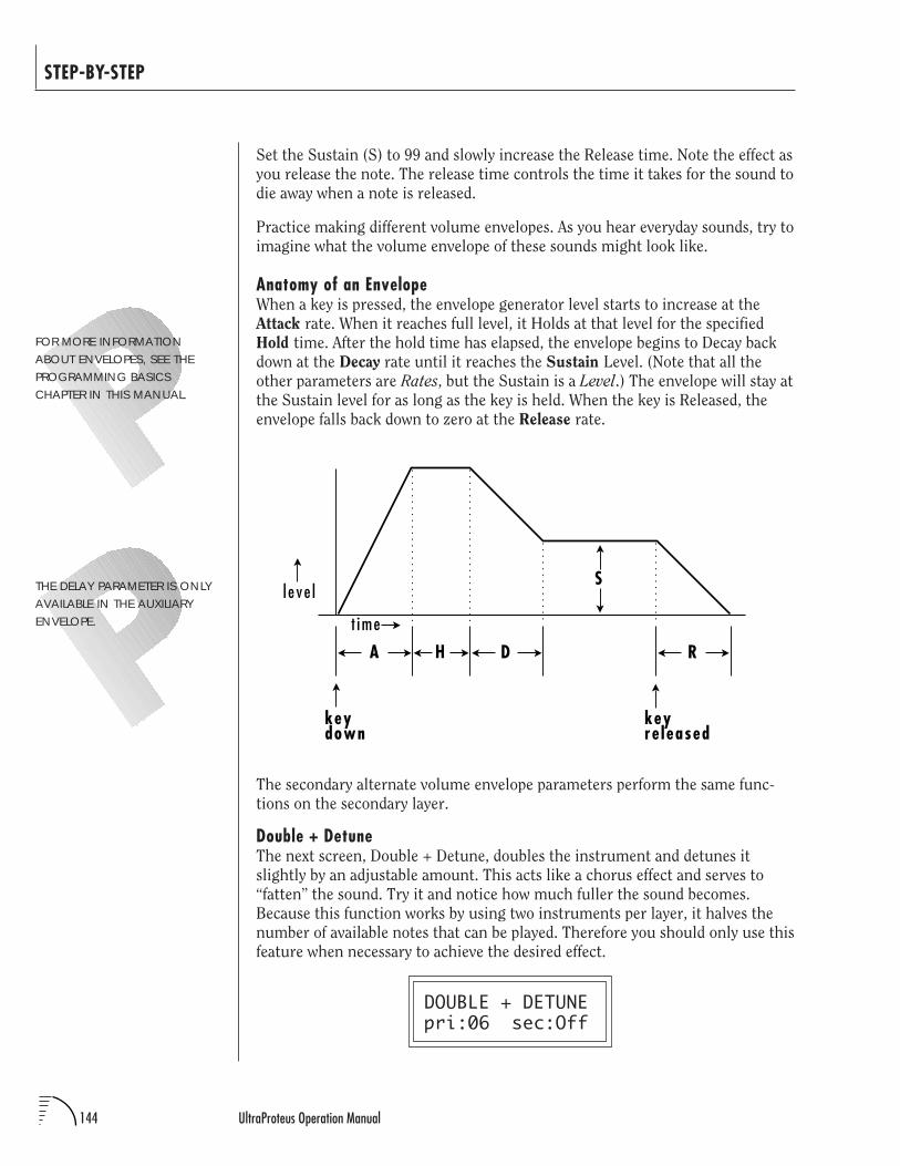
144 UltraProteus Operation Manual
STEP-BY-STEP
Set the Sustain (S) to 99 and slowly increase the Release time. Note the effect as
you release the note. The release time controls the time it takes for the sound to
die away when a note is released.
Practice making different volume envelopes. As you hear everyday sounds, try to
imagine what the volume envelope of these sounds might look like.
Anatomy of an EnvelopeWhen a key is pressed, the envelope generator level starts to increase at the
Attack rate. When it reaches full level, it Holds at that level for the specified
Hold time. After the hold time has elapsed, the envelope begins to Decay back
down at the Decay rate until it reaches the Sustain Level. (Note that all the
other parameters are Rates, but the Sustain is a Level.) The envelope will stay at
the Sustain level for as long as the key is held. When the key is Released, the
envelope falls back down to zero at the Release rate.
FOR MORE INFORMATIONABOUT ENVELOPES, SEE THEPROGRAMMING BASICSCHAPTER IN THIS MANUAL.
THE DELAY PARAMETER IS ONLYAVAILABLE IN THE AUXILIARYENVELOPE.
The secondary alternate volume envelope parameters perform the same func-
tions on the secondary layer.
Double + DetuneThe next screen, Double + Detune, doubles the instrument and detunes it
slightly by an adjustable amount. This acts like a chorus effect and serves to
“fatten” the sound. Try it and notice how much fuller the sound becomes.
Because this function works by using two instruments per layer, it halves the
number of available notes that can be played. Therefore you should only use this
feature when necessary to achieve the desired effect.
DOUBLE + DETUNEpri:06 sec:Off
l e ve l
t ime
keydown
A H D
S
R
keyre leased
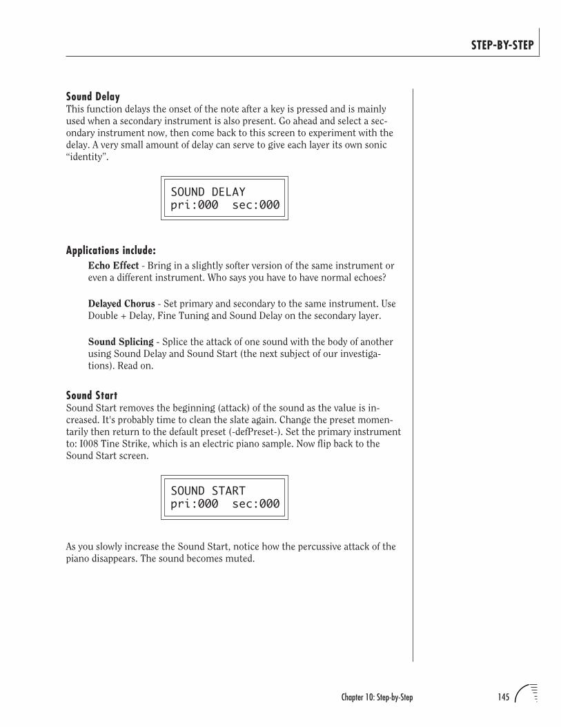
145Chapter 10: Step-by-Step
STEP-BY-STEP
Sound DelayThis function delays the onset of the note after a key is pressed and is mainly
used when a secondary instrument is also present. Go ahead and select a sec-
ondary instrument now, then come back to this screen to experiment with the
delay. A very small amount of delay can serve to give each layer its own sonic
“identity”.
SOUND DELAYpri:000 sec:000
Applications include:Echo Effect - Bring in a slightly softer version of the same instrument or
even a different instrument. Who says you have to have normal echoes?
Delayed Chorus - Set primary and secondary to the same instrument. Use
Double + Delay, Fine Tuning and Sound Delay on the secondary layer.
Sound Splicing - Splice the attack of one sound with the body of another
using Sound Delay and Sound Start (the next subject of our investiga-
tions). Read on.
Sound StartSound Start removes the beginning (attack) of the sound as the value is in-
creased. It's probably time to clean the slate again. Change the preset momen-
tarily then return to the default preset (-defPreset-). Set the primary instrument
to: I008 Tine Strike, which is an electric piano sample. Now flip back to the
Sound Start screen.
SOUND STARTpri:000 sec:000
As you slowly increase the Sound Start, notice how the percussive attack of the
piano disappears. The sound becomes muted.
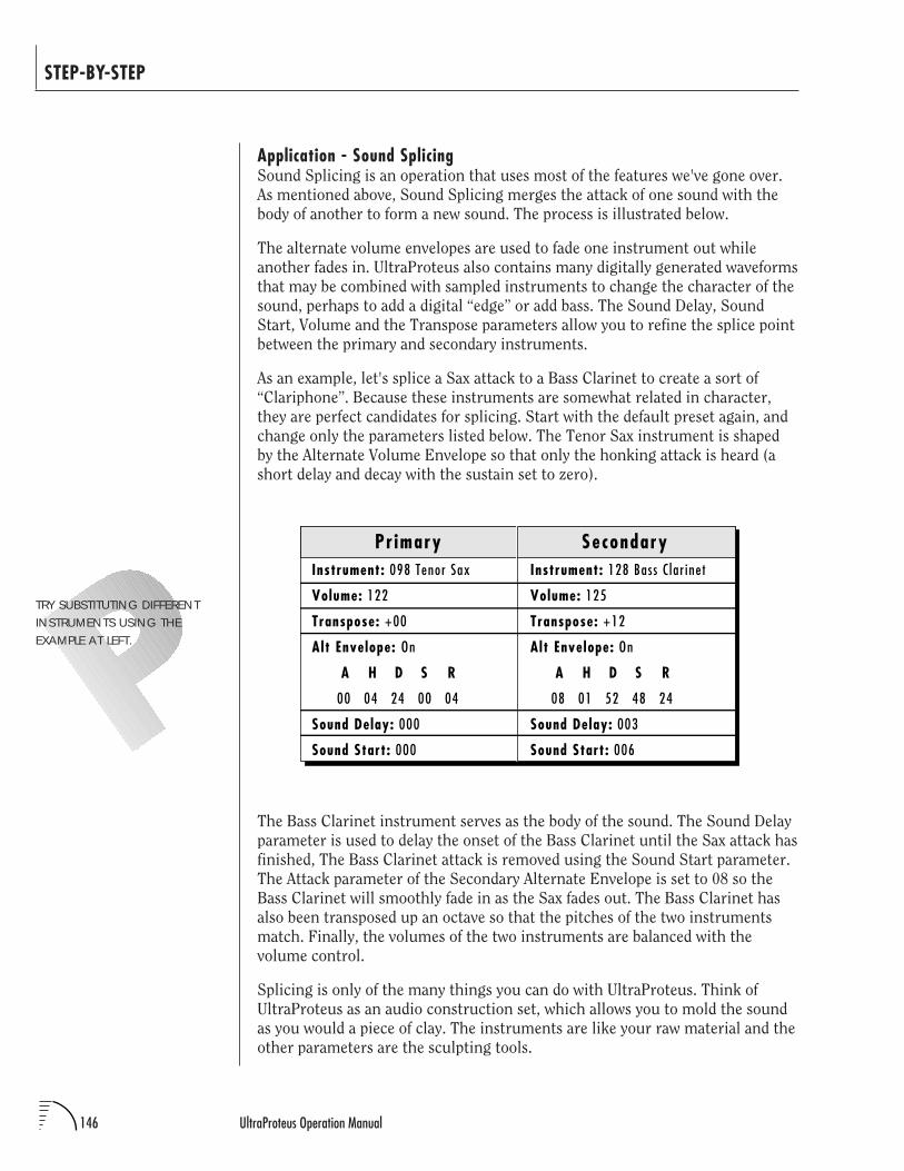
146 UltraProteus Operation Manual
STEP-BY-STEP
Application - Sound SplicingSound Splicing is an operation that uses most of the features we've gone over.
As mentioned above, Sound Splicing merges the attack of one sound with the
body of another to form a new sound. The process is illustrated below.
The alternate volume envelopes are used to fade one instrument out while
another fades in. UltraProteus also contains many digitally generated waveforms
that may be combined with sampled instruments to change the character of the
sound, perhaps to add a digital “edge” or add bass. The Sound Delay, Sound
Start, Volume and the Transpose parameters allow you to refine the splice point
between the primary and secondary instruments.
As an example, let's splice a Sax attack to a Bass Clarinet to create a sort of
“Clariphone”. Because these instruments are somewhat related in character,
they are perfect candidates for splicing. Start with the default preset again, and
change only the parameters listed below. The Tenor Sax instrument is shaped
by the Alternate Volume Envelope so that only the honking attack is heard (a
short delay and decay with the sustain set to zero).
The Bass Clarinet instrument serves as the body of the sound. The Sound Delay
parameter is used to delay the onset of the Bass Clarinet until the Sax attack has
finished, The Bass Clarinet attack is removed using the Sound Start parameter.
The Attack parameter of the Secondary Alternate Envelope is set to 08 so the
Bass Clarinet will smoothly fade in as the Sax fades out. The Bass Clarinet has
also been transposed up an octave so that the pitches of the two instruments
match. Finally, the volumes of the two instruments are balanced with the
volume control.
Splicing is only of the many things you can do with UltraProteus. Think of
UltraProteus as an audio construction set, which allows you to mold the sound
as you would a piece of clay. The instruments are like your raw material and the
other parameters are the sculpting tools.
TRY SUBSTITUTING DIFFERENTINSTRUMENTS USING THEEXAMPLE AT LEFT.
Instrument: 128 Bass C lar inet
Volume: 125
Transpose: +12
Alt Envelope: On
A H D S R
08 01 52 48 24
Sound Delay: 003
Sound Start: 006
Instrument: 098 Tenor Sax
Volume: 122
Transpose: +00
Alt Envelope: On
A H D S R
00 04 24 00 04
Sound Delay: 000
Sound Start: 000
Pr imary Secondary
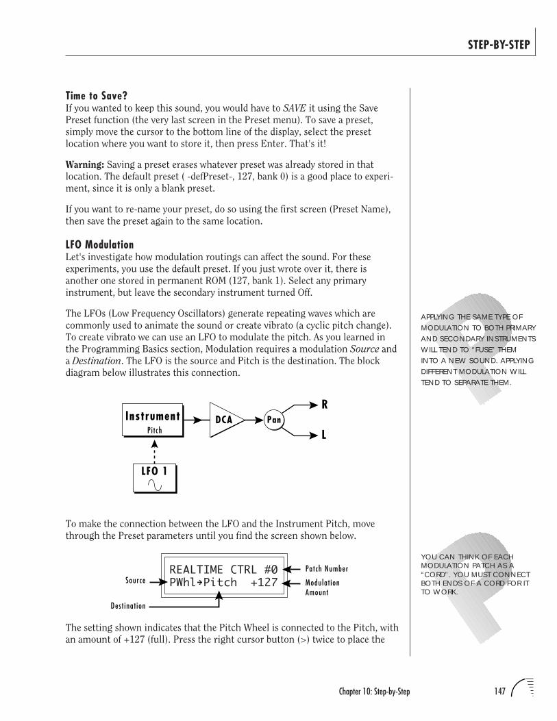
147Chapter 10: Step-by-Step
STEP-BY-STEP
To make the connection between the LFO and the Instrument Pitch, move
through the Preset parameters until you find the screen shown below.
REALTIME CTRL #0PWhl Pitch +127
The setting shown indicates that the Pitch Wheel is connected to the Pitch, with
an amount of +127 (full). Press the right cursor button (>) twice to place the
Time to Save?If you wanted to keep this sound, you would have to SAVE it using the Save
Preset function (the very last screen in the Preset menu). To save a preset,
simply move the cursor to the bottom line of the display, select the preset
location where you want to store it, then press Enter. That's it!
Warning: Saving a preset erases whatever preset was already stored in that
location. The default preset ( -defPreset-, 127, bank 0) is a good place to experi-
ment, since it is only a blank preset.
If you want to re-name your preset, do so using the first screen (Preset Name),
then save the preset again to the same location.
LFO ModulationLet's investigate how modulation routings can affect the sound. For these
experiments, you use the default preset. If you just wrote over it, there is
another one stored in permanent ROM (127, bank 1). Select any primary
instrument, but leave the secondary instrument turned Off.
The LFOs (Low Frequency Oscillators) generate repeating waves which are
commonly used to animate the sound or create vibrato (a cyclic pitch change).
To create vibrato we can use an LFO to modulate the pitch. As you learned in
the Programming Basics section, Modulation requires a modulation Source and
a Destination. The LFO is the source and Pitch is the destination. The block
diagram below illustrates this connection.
YOU CAN THINK OF EACHMODULATION PATCH AS A“CORD”. YOU MUST CONNECTBOTH ENDS OF A CORD FOR ITTO WORK.
R
LPanInstrument DCA
LFO 1
Pi t ch
SourcePatch Number
Modulat ionAmount
Dest inat ion
APPLYING THE SAME TYPE OFMODULATION TO BOTH PRIMARYAND SECONDARY INSTRUMENTSWILL TEND TO “FUSE” THEMINTO A NEW SOUND. APPLYINGDIFFERENT MODULATION WILLTEND TO SEPARATE THEM.
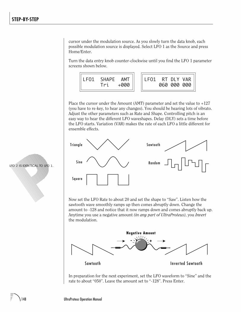
148 UltraProteus Operation Manual
STEP-BY-STEP
cursor under the modulation source. As you slowly turn the data knob, each
possible modulation source is displayed. Select LFO 1 as the Source and press
Home/Enter.
Turn the data entry knob counter-clockwise until you find the LFO 1 parameter
screens shown below.
LFO1 SHAPE AMT LFO1 RT DLY VAR Tri +000 060 000 000
Place the cursor under the Amount (AMT) parameter and set the value to +127
(you have to re-key, to hear any changes). You should be hearing lots of vibrato.
Adjust the other parameters such as Rate and Shape. Controlling pitch is an
easy way to hear the different LFO waveshapes. Delay (DLY) sets a time before
the LFO starts. Variation (VAR) makes the rate of each LFO a little different for
ensemble effects.
Now set the LFO Rate to about 20 and set the shape to “Saw”. Listen how the
sawtooth wave smoothly ramps up then comes abruptly down. Change the
amount to -128 and notice that it now ramps down and comes abruptly back up.
Anytime you use a negative amount (in any part of UltraProteus), you Invert
the modulation.
In preparation for the next experiment, set the LFO waveform to “Sine” and the
rate to about “050”. Leave the amount set to “-128”. Press Enter.
LFO 2 IS IDENTICAL TO LFO 1.
T r i ang l e
Squa re
S i ne
Saw too th
Random
Inve r t ed Saw too th
Negat ive Amount
+-
Saw too th
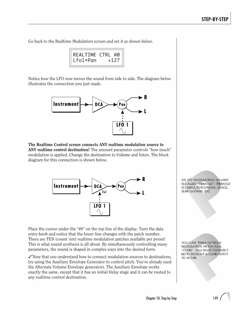
149Chapter 10: Step-by-Step
STEP-BY-STEP
Go back to the Realtime Modulation screen and set it as shown below.
REALTIME CTRL #0Lfo1 Pan +127
Notice how the LFO now moves the sound from side to side. The diagram below
illustrates the connection you just made.
The Realtime Control screen connects ANY realtime modulation source to
ANY realtime control destination! The amount parameter controls “how much”
modulation is applied. Change the destination to Volume and listen. The block
diagram for this connection is shown below.
Place the cursor under the “#0” on the top line of the display. Turn the data
entry knob and notice that the lower line changes with the patch number.
There are TEN (count 'em) realtime modulation patches available per preset!
This is what sound synthesis is all about. By simultaneously controlling many
parameters, the sound is shaped in complex ways into the desired form.
Now that you understand how to connect modulation sources to destinations,
try using the Auxiliary Envelope Generator to control pitch. You've already used
the Alternate Volume Envelope generators. The Auxiliary Envelope works
exactly the same, except that it has an initial Delay stage and it can be routed to
any realtime control destination.
AN LFO MODULATING VOLUMEIS CALLED “TREMOLO”. TREMOLOIS USEFUL FOR ORGAN, VOICE,SURF GUITARS, ETC.
YOU CAN THINK OF EACHMODULATION PATCH AS A“CORD”. YOU MUST CONNECTBOTH ENDS OF A CORD FOR ITTO WORK.
R
LPanInstrument DCA
LFO 1
R
LPanInstrument DCA
LFO 1
Vol
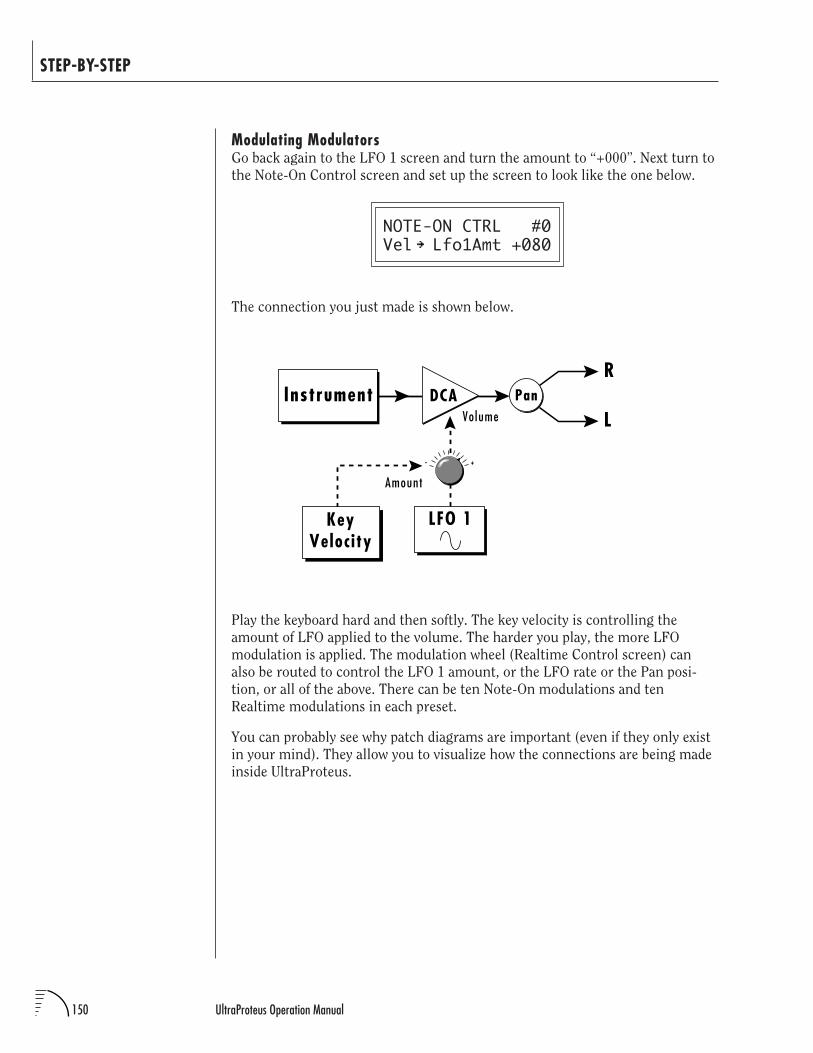
150 UltraProteus Operation Manual
STEP-BY-STEP
Modulating ModulatorsGo back again to the LFO 1 screen and turn the amount to “+000”. Next turn to
the Note-On Control screen and set up the screen to look like the one below.
NOTE-ON CTRL #0Vel Lfo1Amt +080
The connection you just made is shown below.
Play the keyboard hard and then softly. The key velocity is controlling the
amount of LFO applied to the volume. The harder you play, the more LFO
modulation is applied. The modulation wheel (Realtime Control screen) can
also be routed to control the LFO 1 amount, or the LFO rate or the Pan posi-
tion, or all of the above. There can be ten Note-On modulations and ten
Realtime modulations in each preset.
You can probably see why patch diagrams are important (even if they only exist
in your mind). They allow you to visualize how the connections are being made
inside UltraProteus.
R
LPanInstrument DCA
LFO 1KeyVelocity
Volume
Amount
+-
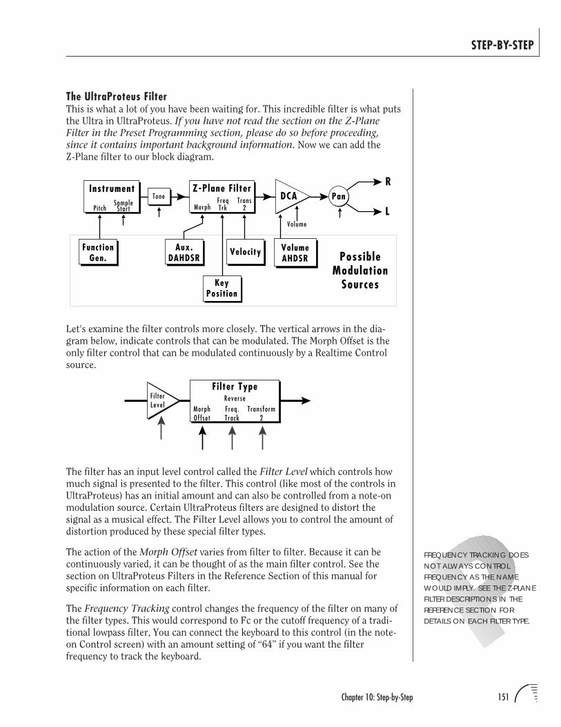
151Chapter 10: Step-by-Step
STEP-BY-STEP
The UltraProteus FilterThis is what a lot of you have been waiting for. This incredible filter is what puts
the Ultra in UltraProteus. If you have not read the section on the Z-PlaneFilter in the Preset Programming section, please do so before proceeding,since it contains important background information. Now we can add the
Z-Plane filter to our block diagram.
The filter has an input level control called the Filter Level which controls how
much signal is presented to the filter. This control (like most of the controls in
UltraProteus) has an initial amount and can also be controlled from a note-on
modulation source. Certain UltraProteus filters are designed to distort the
signal as a musical effect. The Filter Level allows you to control the amount of
distortion produced by these special filter types.
The action of the Morph Offset varies from filter to filter. Because it can be
continuously varied, it can be thought of as the main filter control. See the
section on UltraProteus Filters in the Reference Section of this manual for
specific information on each filter.
The Frequency Tracking control changes the frequency of the filter on many of
the filter types. This would correspond to Fc or the cutoff frequency of a tradi-
tional lowpass filter, You can connect the keyboard to this control (in the note-
on Control screen) with an amount setting of “64” if you want the filter
frequency to track the keyboard.
Let's examine the filter controls more closely. The vertical arrows in the dia-
gram below, indicate controls that can be modulated. The Morph Offset is the
only filter control that can be modulated continuously by a Realtime Control
source.
FREQUENCY TRACKING DOESNOT ALWAYS CONTROLFREQUENCY AS THE NAMEWOULD IMPLY. SEE THE Z-PLANEFILTER DESCRIPTIONS IN THEREFERENCE SECTION FORDETAILS ON EACH FILTER TYPE.
R
LVolume
Pan
VolumeAHDSR
Instrument
Pi t chSample
Star t
ToneZ-Plane Fi lter
DCA
Aux.DAHDSR
Velocity
MorphFreqTrk
FunctionGen. Possible
ModulationSources
Trans2
KeyPosit ion
F i l terLeve l Morph
OffsetFreq.Track
Transform2
ReverseFi lter Type
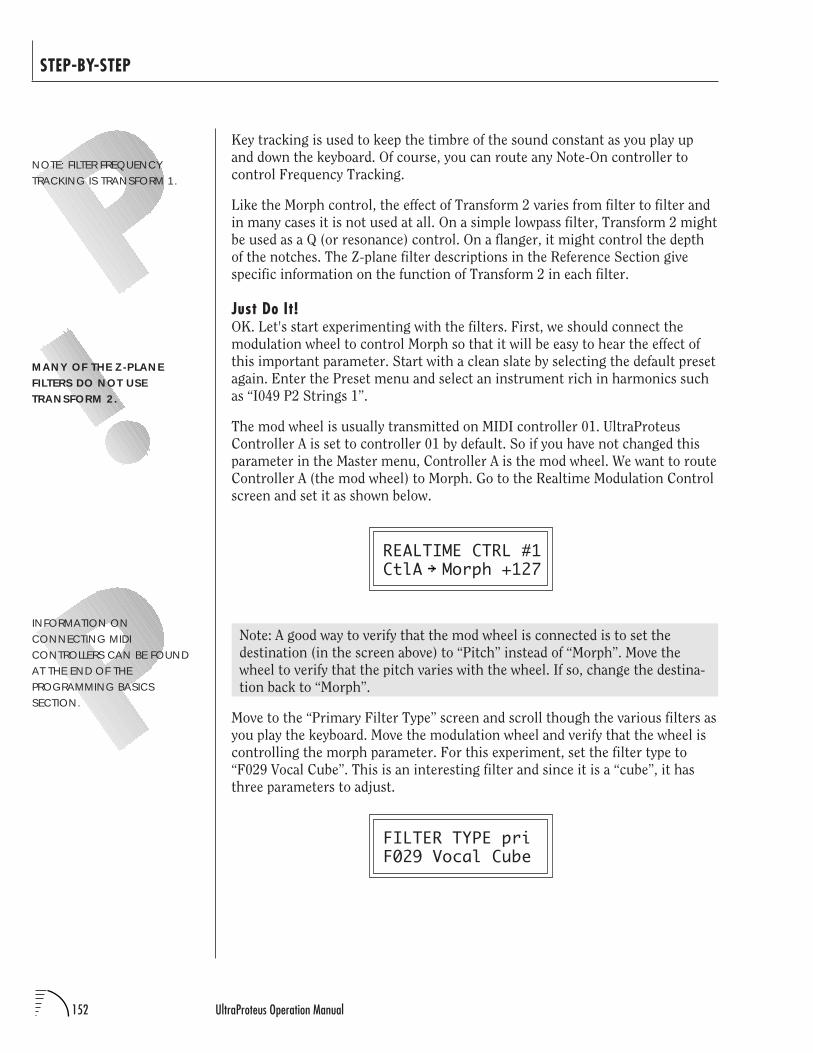
152 UltraProteus Operation Manual
STEP-BY-STEP
Key tracking is used to keep the timbre of the sound constant as you play up
and down the keyboard. Of course, you can route any Note-On controller to
control Frequency Tracking.
Like the Morph control, the effect of Transform 2 varies from filter to filter and
in many cases it is not used at all. On a simple lowpass filter, Transform 2 might
be used as a Q (or resonance) control. On a flanger, it might control the depth
of the notches. The Z-plane filter descriptions in the Reference Section give
specific information on the function of Transform 2 in each filter.
Just Do It!OK. Let's start experimenting with the filters. First, we should connect the
modulation wheel to control Morph so that it will be easy to hear the effect of
this important parameter. Start with a clean slate by selecting the default preset
again. Enter the Preset menu and select an instrument rich in harmonics such
as “I049 P2 Strings 1”.
The mod wheel is usually transmitted on MIDI controller 01. UltraProteus
Controller A is set to controller 01 by default. So if you have not changed this
parameter in the Master menu, Controller A is the mod wheel. We want to route
Controller A (the mod wheel) to Morph. Go to the Realtime Modulation Control
screen and set it as shown below.
REALTIME CTRL #1CtlA Morph +127
Note: A good way to verify that the mod wheel is connected is to set the
destination (in the screen above) to “Pitch” instead of “Morph”. Move the
wheel to verify that the pitch varies with the wheel. If so, change the destina-
tion back to “Morph”.
Move to the “Primary Filter Type” screen and scroll though the various filters as
you play the keyboard. Move the modulation wheel and verify that the wheel is
controlling the morph parameter. For this experiment, set the filter type to
“F029 Vocal Cube”. This is an interesting filter and since it is a “cube”, it has
three parameters to adjust.
FILTER TYPE priF029 Vocal Cube
INFORMATION ONCONNECTING MIDICONTROLLERS CAN BE FOUNDAT THE END OF THEPROGRAMMING BASICSSECTION.
MANY OF THE Z-PLANEFILTERS DO NOT USETRANSFORM 2.
NOTE: FILTER FREQUENCYTRACKING IS TRANSFORM 1.
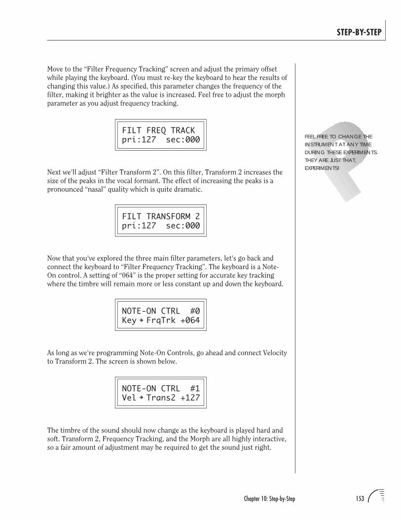
153Chapter 10: Step-by-Step
STEP-BY-STEP
Move to the “Filter Frequency Tracking” screen and adjust the primary offset
while playing the keyboard. (You must re-key the keyboard to hear the results of
changing this value.) As specified, this parameter changes the frequency of the
filter, making it brighter as the value is increased. Feel free to adjust the morph
parameter as you adjust frequency tracking.
FILT FREQ TRACKpri:127 sec:000
Next we'll adjust “Filter Transform 2”. On this filter, Transform 2 increases the
size of the peaks in the vocal formant. The effect of increasing the peaks is a
pronounced “nasal” quality which is quite dramatic.
FILT TRANSFORM 2pri:127 sec:000
Now that you've explored the three main filter parameters, let's go back and
connect the keyboard to “Filter Frequency Tracking”. The keyboard is a Note-
On control. A setting of “064” is the proper setting for accurate key tracking
where the timbre will remain more or less constant up and down the keyboard.
NOTE-ON CTRL #0Key FrqTrk +064
As long as we're programming Note-On Controls, go ahead and connect Velocity
to Transform 2. The screen is shown below.
NOTE-ON CTRL #1Vel Trans2 +127
The timbre of the sound should now change as the keyboard is played hard and
soft. Transform 2, Frequency Tracking, and the Morph are all highly interactive,
so a fair amount of adjustment may be required to get the sound just right.
FEEL FREE TO CHANGE THEINSTRUMENT AT ANY TIMEDURING THESE EXPERIMENTS.THEY ARE JUST THAT,EXPERIMENTS!
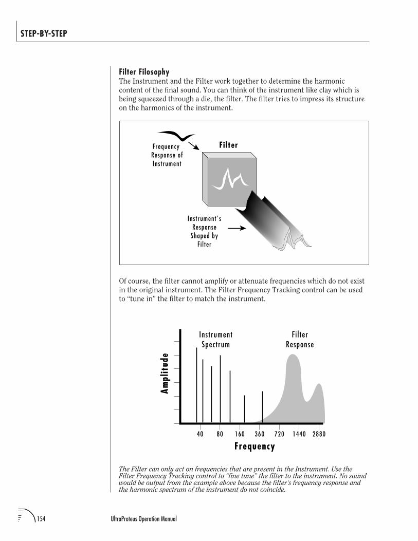
154 UltraProteus Operation Manual
STEP-BY-STEP
Filter FilosophyThe Instrument and the Filter work together to determine the harmonic
content of the final sound. You can think of the instrument like clay which is
being squeezed through a die, the filter. The filter tries to impress its structure
on the harmonics of the instrument.
Of course, the filter cannot amplify or attenuate frequencies which do not exist
in the original instrument. The Filter Frequency Tracking control can be used
to “tune in” the filter to match the instrument.
Frequency Response ofIns t rument
Ins t rument'sResponse
Shaped byF i l ter
Fi lter
The Filter can only act on frequencies that are present in the Instrument. Use theFilter Frequency Tracking control to “fine tune” the filter to the instrument. No soundwould be output from the example above because the filter's frequency response andthe harmonic spectrum of the instrument do not coincide.
Frequency
F i l terResponse
Ins t rumentSpectrum
40 80 160 360 720 1440 2880
Ampl
itud
e
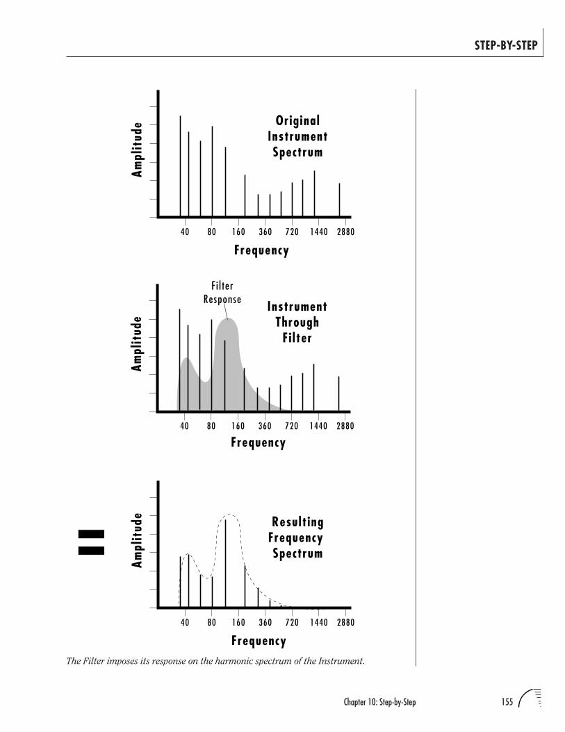
155Chapter 10: Step-by-Step
STEP-BY-STEP
Frequency40 80 160 360 720 1440 2880
Ampl
itud
e Result ingFrequency Spectrum
Frequency
F i l terResponse Instrument
ThroughFi lter
40 80 160 360 720 1440 2880
Ampl
itud
e
40 80 160 360 720 1440 2880
Frequency
OriginalInstrumentSpectrum
Ampl
itud
e
The Filter imposes its response on the harmonic spectrum of the Instrument.
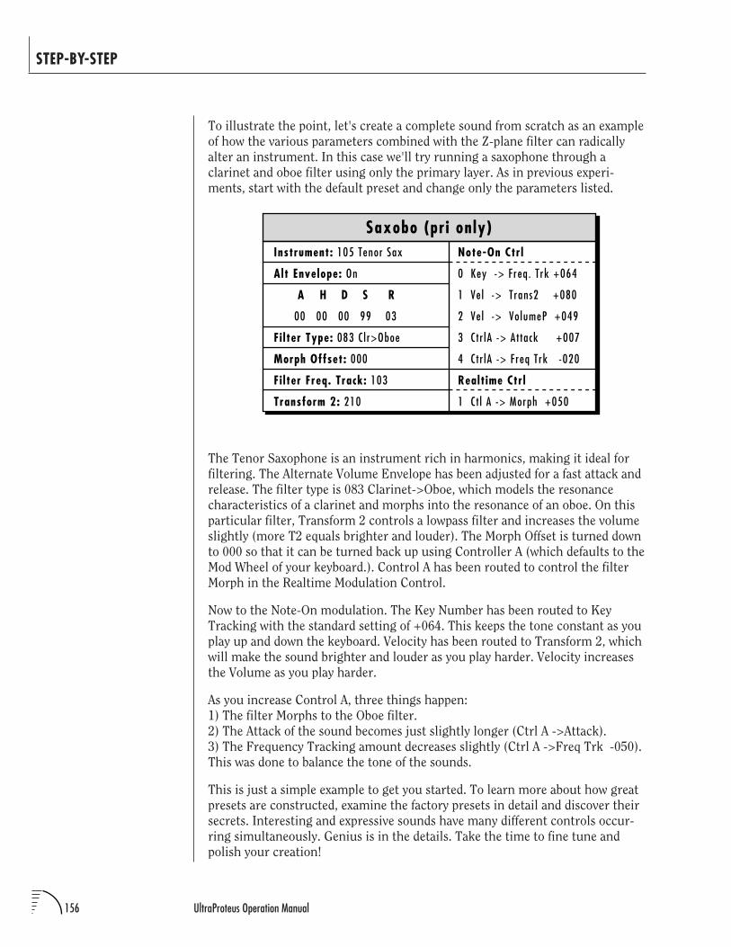
156 UltraProteus Operation Manual
STEP-BY-STEP
To illustrate the point, let's create a complete sound from scratch as an example
of how the various parameters combined with the Z-plane filter can radically
alter an instrument. In this case we'll try running a saxophone through a
clarinet and oboe filter using only the primary layer. As in previous experi-
ments, start with the default preset and change only the parameters listed.
Instrument: 105 Tenor Sax
Alt Envelope: On
A H D S R
00 00 00 99 03
Fi lter Type: 083 C l r>Oboe
Morph Offset: 000
Fi lter Freq. Track: 103
Transform 2: 210
Saxobo (pri only)Note-On Ctrl
0 Key -> Freq. Trk +064
1 Ve l -> Trans2 +080
2 Ve l -> Vo lumeP +049
3 Ctr lA -> At tack +007
4 C tr lA -> Freq Trk -020
Realt ime Ctrl
1 Ct l A -> Morph +050
The Tenor Saxophone is an instrument rich in harmonics, making it ideal for
filtering. The Alternate Volume Envelope has been adjusted for a fast attack and
release. The filter type is 083 Clarinet->Oboe, which models the resonance
characteristics of a clarinet and morphs into the resonance of an oboe. On this
particular filter, Transform 2 controls a lowpass filter and increases the volume
slightly (more T2 equals brighter and louder). The Morph Offset is turned down
to 000 so that it can be turned back up using Controller A (which defaults to the
Mod Wheel of your keyboard.). Control A has been routed to control the filter
Morph in the Realtime Modulation Control.
Now to the Note-On modulation. The Key Number has been routed to Key
Tracking with the standard setting of +064. This keeps the tone constant as you
play up and down the keyboard. Velocity has been routed to Transform 2, which
will make the sound brighter and louder as you play harder. Velocity increases
the Volume as you play harder.
As you increase Control A, three things happen:
1) The filter Morphs to the Oboe filter.
2) The Attack of the sound becomes just slightly longer (Ctrl A ->Attack).
3) The Frequency Tracking amount decreases slightly (Ctrl A ->Freq Trk -050).
This was done to balance the tone of the sounds.
This is just a simple example to get you started. To learn more about how great
presets are constructed, examine the factory presets in detail and discover their
secrets. Interesting and expressive sounds have many different controls occur-
ring simultaneously. Genius is in the details. Take the time to fine tune and
polish your creation!
157Chapter 10: Step-by-Step
STEP-BY-STEP
MorphologyThe best and ultimately the only way to choose filters is to try them out.
UltraProteus is no mere mortal synthesizer with a single filter. UltraProteus has
288 filter types to choose from. Think of the filters as you do instruments:
entities which have a particular sound. As you learn what the instrument and
the filters sound like, you can mix and match them to suit your needs.
A flanger filter (which is a parametric EQ with closely-spaced notches)
sounds like a traditional flanger when swept. If the frequency of the flanger
is controlled by key velocity and not swept, the flanger can simulate
different plucks on a string or strikes on a surface such as a cymbal.
The need for Keyboard Tracking is reduced when using a parametric EQ
since the high frequencies are preserved (unlike a lowpass filter).
Time-variant filter sweeps are good for traditional synthesizer effects such
as resonant sweeps, flanges, phasing, stereo panning, vowels, etc. Time-
invariant filters are useful for distortion, simulating instrument reso-
nances, plucked strings, cymbals strikes, etc.
Correlate the DCA envelope to emphasize or minimize parallel filter
attack and release characteristics.
Try using vibrato (LFO to pitch) with vocal filters for more realistic vocal
simulations.
Velocity and Key Number generally alter the timbre in expressive presets.
Also, Harder (faster) usually equals Brighter.
Natural sounds tend to use low Q filters.
Fixed Formant Filters:Can reduce the unwanted effect of pitch shifting the samples
(munchkinization).
Simulate instrument body resonances
Simulate cymbal strikes, with variation in the stick position
Simulate woodwind instrument resonance
Simulate guitar and string plucks with variation in pick position
Swept Filters:Simulate flangers
Can be used for traditional synthesizer lowpass filter effects
Can pick individual harmonics out of complex sounds
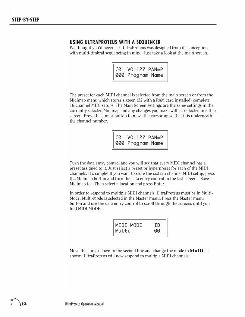
158 UltraProteus Operation Manual
STEP-BY-STEP
USING ULTRAPROTEUS WITH A SEQUENCERWe thought you’d never ask. UltraProteus was designed from its conception
with multi-timbral sequencing in mind. Just take a look at the main screen.
C01 VOL127 PAN=P000 Program Name
The preset for each MIDI channel is selected from the main screen or from the
Midimap menu which stores sixteen (32 with a RAM card installed) complete
16-channel MIDI setups. The Main Screen settings are the same settings in the
currently selected Midimap and any changes you make will be reflected in either
screen. Press the cursor button to move the cursor up so that it is underneath
the channel number.
C01 VOL127 PAN=P000 Program Name
Turn the data entry control and you will see that every MIDI channel has a
preset assigned to it. Just select a preset or hyperpreset for each of the MIDI
channels. It’s simple! If you want to store the sixteen channel MIDI setup, press
the Midimap button and turn the data entry control to the last screen, “Save
Midimap to”. Then select a location and press Enter.
In order to respond to multiple MIDI channels, UltraProteus must be in Multi-
Mode. Multi-Mode is selected in the Master menu. Press the Master menu
button and use the data entry control to scroll through the screens until you
find MIDI MODE.
MIDI MODE IDMulti 00
Move the cursor down to the second line and change the mode to Multi as
shown. UltraProteus will now respond to multiple MIDI channels.
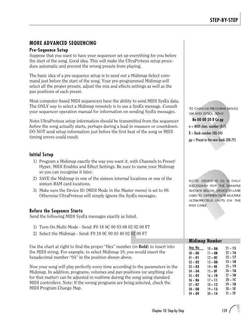
159Chapter 10: Step-by-Step
STEP-BY-STEP
Midimap NumberMap Hx00 = 0001 = 0102 = 0203 = 0304 = 0405 = 0506 = 0607 = 0708 = 0809 = 09
21 = 1522 = 1623 = 1724 = 1825 = 1926 = 1A27 = 1B28 = 1C29 = 1D30 = 1E31 = 1F
10 = 0A11 = 0B12 = 0C13 = 0D14 = 0E15 = 0F16 = 1017 = 1118 = 1219 = 1320 = 14
MORE ADVANCED SEQUENCINGPre-Sequence SetupSuppose that you want to have your sequencer set up everything for you before
the start of the song. Good idea. This will make the UltraProteus setup proce-
dure automatic and prevent the wrong presets from playing.
The basic idea of a pre-sequence setup is to send out a Midimap Select com-
mand just before the start of the song. Your pre-programmed Midimap will
select all the proper presets, adjust the mix and effects settings as well as the
pan positions of each preset.
Most computer-based MIDI sequencers have the ability to send MIDI SysEx data.
The ONLY way to select a Midimap remotely is to use a SysEx message. Consult
your sequencer operation manual for information on sending SysEx messages.
Note: UltraProteus setup information should be transmitted from the sequencer
before the song actually starts, perhaps during a lead-in measure or countdown.
DO NOT send setup information just before the first beat of the song or MIDI
timing errors could result.
Initial Setup1) Program a Midimap exactly the way you want it, with Channels to Preset/
Hyper, MIDI Enables and Effect Settings. Be sure to name your Midimap
so you can recognize it later.
2) SAVE the Midimap in one of the sixteen internal locations or one of the
sixteen RAM card locations.
3) Make sure the Device ID (MIDI Mode in the Master menu) is set to 00.
Otherwise UltraProteus will simply ignore the SysEx messages.
Before the Sequence StartsSend the following MIDI SysEx messages exactly as listed.
1) Turn On Multi-Mode - Send: F0 18 0C 00 03 08 02 02 00 F7
2) Select the Midimap - Send: F0 18 0C 00 03 40 02 02 00 F7
Use the chart at right to find the proper “Hex” number (in Bold) to insert into
the MIDI string. For example, to select Midimap 10, you would insert the
hexadecimal number “0A” in the position shown above.
Now your song will play perfectly every time according to the parameters in the
Midimap. In addition, programs, volumes and pan positions (or anything else
for that matter) can be adjusted in realtime during the song using standard
MIDI controllers. Note: If the wrong programs are being selected, check the
MIDI Program Change Map.
NOTE: DEVICE ID 00 IS ONLYNECESSARY FOR THE EXAMPLESHOWN BELOW. DEVICE ID's AREUSED TO DIFFERENTIATE MULTIPLEULTRAPROTEUS UNITS ON THEMIDI CABLE.
TO CHANGE PROGRAM BANKSVIA MIDI SYSEX, SEND:
Bn 00 00 20 ll Cn pp
n = MIDI chan. number (0-F)
ll = Bank number (00-04)
pp = Preset in the new bank (00-7F)
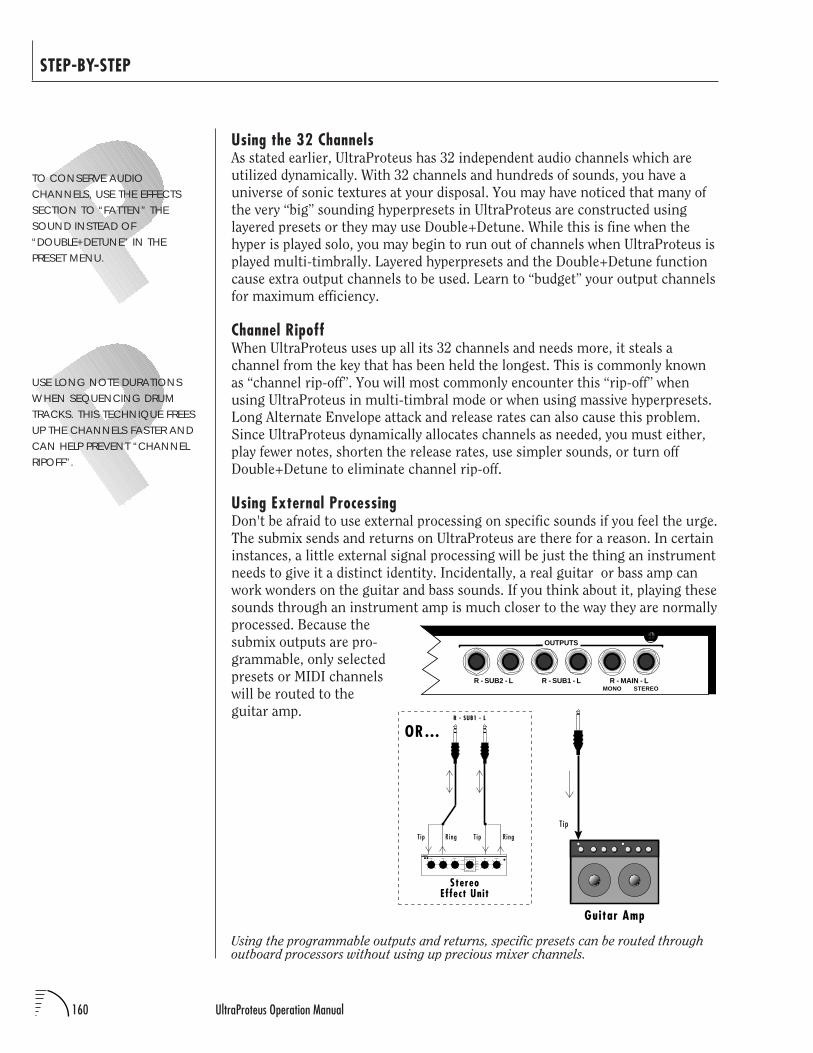
160 UltraProteus Operation Manual
STEP-BY-STEP
Using the programmable outputs and returns, specific presets can be routed throughoutboard processors without using up precious mixer channels.
R - SUB2 - L R - SUB1 - L R - MAIN - LMONO STEREO
OUTPUTS
T ip
Guitar Amp
R - SUB1 - L
RingT ip RingT ip
StereoEffect Unit
OR…
Using the 32 ChannelsAs stated earlier, UltraProteus has 32 independent audio channels which are
utilized dynamically. With 32 channels and hundreds of sounds, you have a
universe of sonic textures at your disposal. You may have noticed that many of
the very “big” sounding hyperpresets in UltraProteus are constructed using
layered presets or they may use Double+Detune. While this is fine when the
hyper is played solo, you may begin to run out of channels when UltraProteus is
played multi-timbrally. Layered hyperpresets and the Double+Detune function
cause extra output channels to be used. Learn to “budget” your output channels
for maximum efficiency.
Channel RipoffWhen UltraProteus uses up all its 32 channels and needs more, it steals a
channel from the key that has been held the longest. This is commonly known
as “channel rip-off”. You will most commonly encounter this “rip-off” when
using UltraProteus in multi-timbral mode or when using massive hyperpresets.
Long Alternate Envelope attack and release rates can also cause this problem.
Since UltraProteus dynamically allocates channels as needed, you must either,
play fewer notes, shorten the release rates, use simpler sounds, or turn off
Double+Detune to eliminate channel rip-off.
Using External ProcessingDon't be afraid to use external processing on specific sounds if you feel the urge.
The submix sends and returns on UltraProteus are there for a reason. In certain
instances, a little external signal processing will be just the thing an instrument
needs to give it a distinct identity. Incidentally, a real guitar or bass amp can
work wonders on the guitar and bass sounds. If you think about it, playing these
sounds through an instrument amp is much closer to the way they are normally
processed. Because the
submix outputs are pro-
grammable, only selected
presets or MIDI channels
will be routed to the
guitar amp.
TO CONSERVE AUDIOCHANNELS, USE THE EFFECTSSECTION TO “FATTEN” THESOUND INSTEAD OF“DOUBLE+DETUNE” IN THEPRESET MENU.
USE LONG NOTE DURATIONSWHEN SEQUENCING DRUMTRACKS. THIS TECHNIQUE FREESUP THE CHANNELS FASTER ANDCAN HELP PREVENT “CHANNELRIPOFF”.
161Chapter 11: Reference Section
UltraProteus REFERENCE SECTION
Preset Listing ..................................................................................... 162Instrument Listing .............................................................................. 164Drawbar Diagrams ............................................................................. 171Instrument Locations .......................................................................... 172Percussion Instrument Locations .......................................................... 173Z-Plane Filter Descriptions .................................................................. 178Loop Offset Sample Locations ............................................................. 235Function Generator Curves .................................................................. 239Func. Gen., LFO & Envelope Specs ....................................................... 247Technical Specifications ....................................................................... 248MIDI Specifications ............................................................................. 249
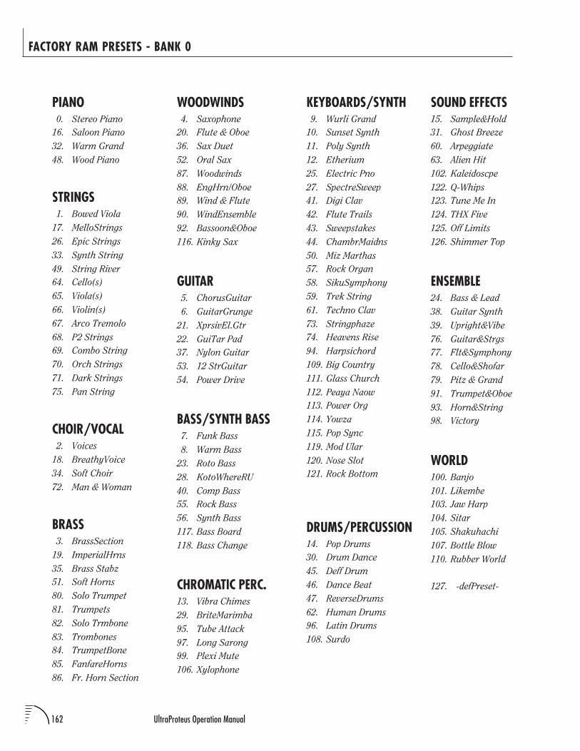
162 UltraProteus Operation Manual
FACTORY RAM PRESETS - BANK 0
WOODWINDS4. Saxophone
20. Flute & Oboe
36. Sax Duet
52. Oral Sax
87. Woodwinds
88. EngHrn/Oboe
89. Wind & Flute
90. WindEnsemble
92. Bassoon&Oboe
116. Kinky Sax
GUITAR5. ChorusGuitar
6. GuitarGrunge
21. XprsivEl.Gtr
22. GuiTar Pad
37. Nylon Guitar
53. 12 StrGuitar
54. Power Drive
BASS/SYNTH BASS7. Funk Bass
8. Warm Bass
23. Roto Bass
28. KotoWhereRU
40. Comp Bass
55. Rock Bass
56. Synth Bass
117. Bass Board
118. Bass Change
CHROMATIC PERC.13. Vibra Chimes
29. BriteMarimba
95. Tube Attack
97. Long Sarong
99. Plexi Mute
106. Xylophone
PIANO0. Stereo Piano
16. Saloon Piano
32. Warm Grand
48. Wood Piano
STRINGS1. Bowed Viola
17. MelloStrings
26. Epic Strings
33. Synth String
49. String River
64. Cello(s)
65. Viola(s)
66. Violin(s)
67. Arco Tremolo
68. P2 Strings
69. Combo String
70. Orch Strings
71. Dark Strings
75. Pan String
CHOIR/VOCAL2. Voices
18. BreathyVoice
34. Soft Choir
72. Man & Woman
BRASS3. BrassSection
19. ImperialHrns
35. Brass Stabz
51. Soft Horns
80. Solo Trumpet
81. Trumpets
82. Solo Trmbone
83. Trombones
84. TrumpetBone
85. FanfareHorns
86. Fr. Horn Section
KEYBOARDS/SYNTH9. Wurli Grand
10. Sunset Synth
11. Poly Synth
12. Etherium
25. Electric Pno
27. SpectreSweep
41. Digi Clav
42. Flute Trails
43. Sweepstakes
44. ChambrMaidns
50. Miz Marthas
57. Rock Organ
58. SikuSymphony
59. Trek String
61. Techno Clav
73. Stringphaze
74. Heavens Rise
94. Harpsichord
109. Big Country
111. Glass Church
112. Peaya Naow
113. Power Org
114. Yowza
115. Pop Sync
119. Mod Ular
120. Nose Slot
121. Rock Bottom
DRUMS/PERCUSSION14. Pop Drums
30. Drum Dance
45. Deff Drum
46. Dance Beat
47. ReverseDrums
62. Human Drums
96. Latin Drums
108. Surdo
SOUND EFFECTS15. Sample&Hold
31. Ghost Breeze
60. Arpeggiate
63. Alien Hit
102. Kaleidoscpe
122. Q-Whips
123. Tune Me In
124. THX Five
125. Off Limits
126. Shimmer Top
ENSEMBLE24. Bass & Lead
38. Guitar Synth
39. Upright&Vibe
76. Guitar&Strgs
77. Flt&Symphony
78. Cello&Shofar
79. Pitz & Grand
91. Trumpet&Oboe
93. Horn&String
98. Victory
WORLD100. Banjo
101. Likembe
103. Jaw Harp
104. Sitar
105. Shakuhachi
107. Bottle Blow
110. Rubber World
127. -defPreset-
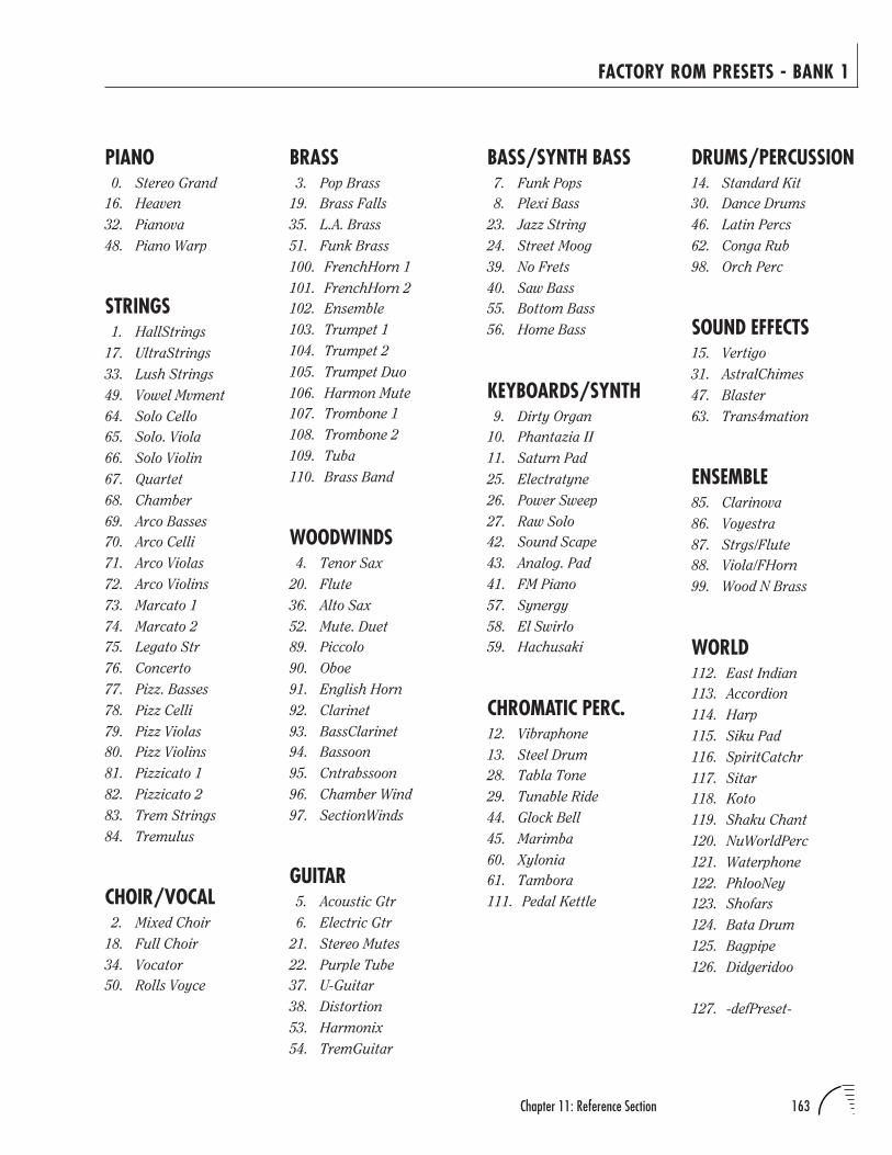
163Chapter 11: Reference Section
FACTORY ROM PRESETS - BANK 1
PIANO0. Stereo Grand
16. Heaven
32. Pianova
48. Piano Warp
STRINGS1. HallStrings
17. UltraStrings
33. Lush Strings
49. Vowel Mvment
64. Solo Cello
65. Solo. Viola
66. Solo Violin
67. Quartet
68. Chamber
69. Arco Basses
70. Arco Celli
71. Arco Violas
72. Arco Violins
73. Marcato 1
74. Marcato 2
75. Legato Str
76. Concerto
77. Pizz. Basses
78. Pizz Celli
79. Pizz Violas
80. Pizz Violins
81. Pizzicato 1
82. Pizzicato 2
83. Trem Strings
84. Tremulus
CHOIR/VOCAL2. Mixed Choir
18. Full Choir
34. Vocator
50. Rolls Voyce
DRUMS/PERCUSSION14. Standard Kit
30. Dance Drums
46. Latin Percs
62. Conga Rub
98. Orch Perc
SOUND EFFECTS15. Vertigo
31. AstralChimes
47. Blaster
63. Trans4mation
ENSEMBLE85. Clarinova
86. Voyestra
87. Strgs/Flute
88. Viola/FHorn
99. Wood N Brass
WORLD112. East Indian
113. Accordion
114. Harp
115. Siku Pad
116. SpiritCatchr
117. Sitar
118. Koto
119. Shaku Chant
120. NuWorldPerc
121. Waterphone
122. PhlooNey
123. Shofars
124. Bata Drum
125. Bagpipe
126. Didgeridoo
127. -defPreset-
BASS/SYNTH BASS7. Funk Pops
8. Plexi Bass
23. Jazz String
24. Street Moog
39. No Frets
40. Saw Bass
55. Bottom Bass
56. Home Bass
KEYBOARDS/SYNTH9. Dirty Organ
10. Phantazia II
11. Saturn Pad
25. Electratyne
26. Power Sweep
27. Raw Solo
42. Sound Scape
43. Analog. Pad
41. FM Piano
57. Synergy
58. El Swirlo
59. Hachusaki
CHROMATIC PERC.12. Vibraphone
13. Steel Drum
28. Tabla Tone
29. Tunable Ride
44. Glock Bell
45. Marimba
60. Xylonia
61. Tambora
111. Pedal Kettle
BRASS3. Pop Brass
19. Brass Falls
35. L.A. Brass
51. Funk Brass
100. FrenchHorn 1
101. FrenchHorn 2
102. Ensemble
103. Trumpet 1
104. Trumpet 2
105. Trumpet Duo
106. Harmon Mute
107. Trombone 1
108. Trombone 2
109. Tuba
110. Brass Band
WOODWINDS4. Tenor Sax
20. Flute
36. Alto Sax
52. Mute. Duet
89. Piccolo
90. Oboe
91. English Horn
92. Clarinet
93. BassClarinet
94. Bassoon
95. Cntrabssoon
96. Chamber Wind
97. SectionWinds
GUITAR5. Acoustic Gtr
6. Electric Gtr
21. Stereo Mutes
22. Purple Tube
37. U-Guitar
38. Distortion
53. Harmonix
54. TremGuitar
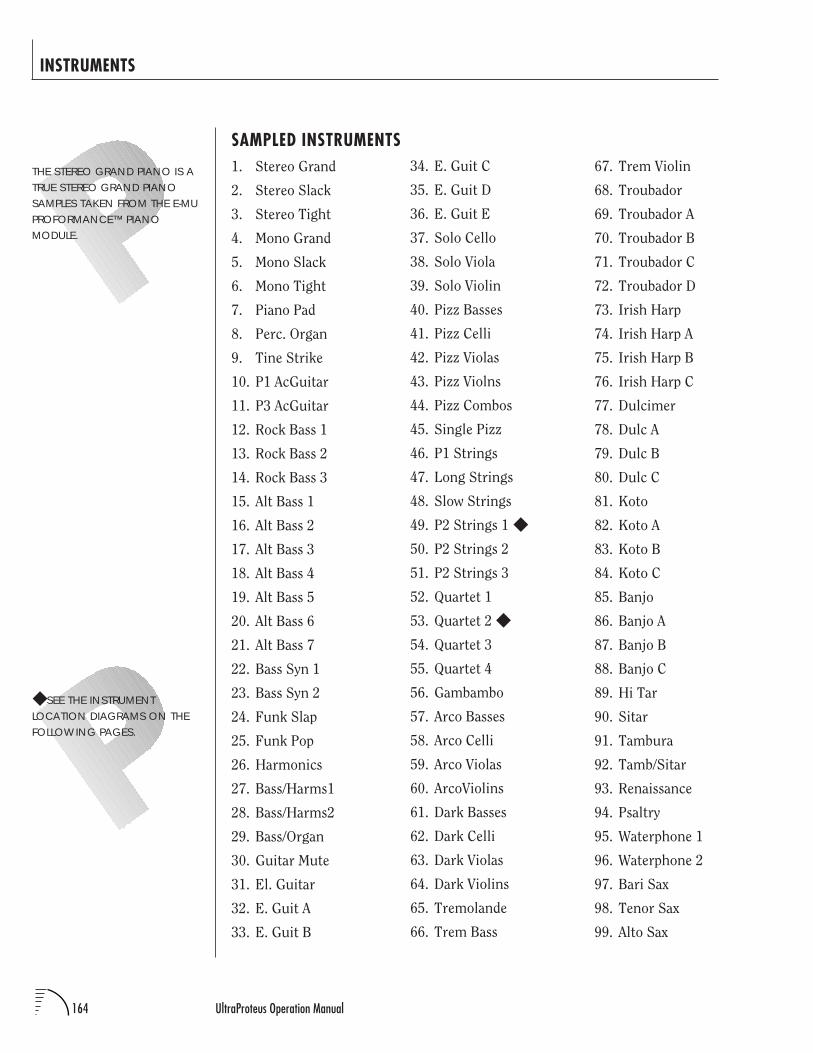
164 UltraProteus Operation Manual
INSTRUMENTS
SAMPLED INSTRUMENTS1. Stereo Grand
2. Stereo Slack
3. Stereo Tight
4. Mono Grand
5. Mono Slack
6. Mono Tight
7. Piano Pad
8. Perc. Organ
9. Tine Strike
10. P1 AcGuitar
11. P3 AcGuitar
12. Rock Bass 1
13. Rock Bass 2
14. Rock Bass 3
15. Alt Bass 1
16. Alt Bass 2
17. Alt Bass 3
18. Alt Bass 4
19. Alt Bass 5
20. Alt Bass 6
21. Alt Bass 7
22. Bass Syn 1
23. Bass Syn 2
24. Funk Slap
25. Funk Pop
26. Harmonics
27. Bass/Harms1
28. Bass/Harms2
29. Bass/Organ
30. Guitar Mute
31. El. Guitar
32. E. Guit A
33. E. Guit B
67. Trem Violin
68. Troubador
69. Troubador A
70. Troubador B
71. Troubador C
72. Troubador D
73. Irish Harp
74. Irish Harp A
75. Irish Harp B
76. Irish Harp C
77. Dulcimer
78. Dulc A
79. Dulc B
80. Dulc C
81. Koto
82. Koto A
83. Koto B
84. Koto C
85. Banjo
86. Banjo A
87. Banjo B
88. Banjo C
89. Hi Tar
90. Sitar
91. Tambura
92. Tamb/Sitar
93. Renaissance
94. Psaltry
95. Waterphone 1
96. Waterphone 2
97. Bari Sax
98. Tenor Sax
99. Alto Sax
34. E. Guit C
35. E. Guit D
36. E. Guit E
37. Solo Cello
38. Solo Viola
39. Solo Violin
40. Pizz Basses
41. Pizz Celli
42. Pizz Violas
43. Pizz Violns
44. Pizz Combos
45. Single Pizz
46. P1 Strings
47. Long Strings
48. Slow Strings
49. P2 Strings 1
50. P2 Strings 2
51. P2 Strings 3
52. Quartet 1
53. Quartet 2
54. Quartet 3
55. Quartet 4
56. Gambambo
57. Arco Basses
58. Arco Celli
59. Arco Violas
60. ArcoViolins
61. Dark Basses
62. Dark Celli
63. Dark Violas
64. Dark Violins
65. Tremolande
66. Trem Bass
THE STEREO GRAND PIANO IS ATRUE STEREO GRAND PIANOSAMPLES TAKEN FROM THE E-MUPROFORMANCE™ PIANOMODULE.
SEE THE INSTRUMENTLOCATION DIAGRAMS ON THEFOLLOWING PAGES.
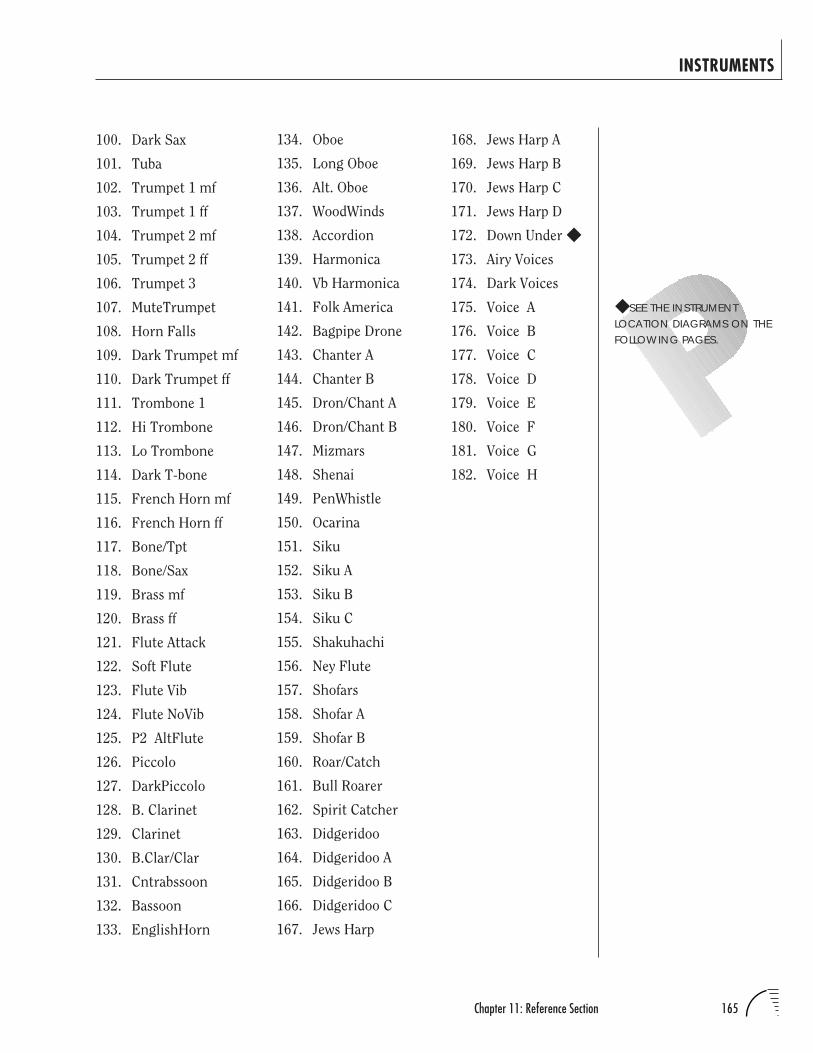
165Chapter 11: Reference Section
INSTRUMENTS
100. Dark Sax
101. Tuba
102. Trumpet 1 mf
103. Trumpet 1 ff
104. Trumpet 2 mf
105. Trumpet 2 ff
106. Trumpet 3
107. MuteTrumpet
108. Horn Falls
109. Dark Trumpet mf
110. Dark Trumpet ff
111. Trombone 1
112. Hi Trombone
113. Lo Trombone
114. Dark T-bone
115. French Horn mf
116. French Horn ff
117. Bone/Tpt
118. Bone/Sax
119. Brass mf
120. Brass ff
121. Flute Attack
122. Soft Flute
123. Flute Vib
124. Flute NoVib
125. P2 AltFlute
126. Piccolo
127. DarkPiccolo
128. B. Clarinet
129. Clarinet
130. B.Clar/Clar
131. Cntrabssoon
132. Bassoon
133. EnglishHorn
168. Jews Harp A
169. Jews Harp B
170. Jews Harp C
171. Jews Harp D
172. Down Under
173. Airy Voices
174. Dark Voices
175. Voice A
176. Voice B
177. Voice C
178. Voice D
179. Voice E
180. Voice F
181. Voice G
182. Voice H
134. Oboe
135. Long Oboe
136. Alt. Oboe
137. WoodWinds
138. Accordion
139. Harmonica
140. Vb Harmonica
141. Folk America
142. Bagpipe Drone
143. Chanter A
144. Chanter B
145. Dron/Chant A
146. Dron/Chant B
147. Mizmars
148. Shenai
149. PenWhistle
150. Ocarina
151. Siku
152. Siku A
153. Siku B
154. Siku C
155. Shakuhachi
156. Ney Flute
157. Shofars
158. Shofar A
159. Shofar B
160. Roar/Catch
161. Bull Roarer
162. Spirit Catcher
163. Didgeridoo
164. Didgeridoo A
165. Didgeridoo B
166. Didgeridoo C
167. Jews Harp
SEE THE INSTRUMENTLOCATION DIAGRAMS ON THEFOLLOWING PAGES.
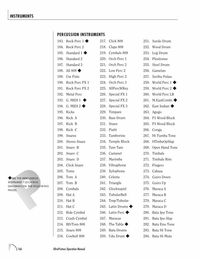
166 UltraProteus Operation Manual
INSTRUMENTS
PERCUSSION INSTRUMENTS183. Rock Perc 1
184. Rock Perc 2
185. Standard 1
186. Standard 2
187. Standard 3
188. All 808
189. Use Fists
190. Rock Perc FX 1
191. Rock Perc FX 2
192. Metal Perc
193. G. MIDI 1
194. G. MIDI 2
195. Kicks
196. Kick A
197. Kick B
198. Kick C
199. Snares
200. Stereo Snare
201. Snare B
202. Snare C
203. Snare D
204. Click Snare
205. Toms
206. Tom A
207. Tom B
208. Cymbals
209. Hat A
210. Hat B
211. Hat C
212. Ride Cymbal
213. Crash Cymbal
214. BD/Tom 808
215. Snare 808
216. Cowbell 808
SEE THE PERCUSSIONINSTRUMENT LOCATIONDIAGRAMS ON THE FOLLOWINGPAGES.
251. Surdo Drum
252. Wood Drum
253. Log Drum
254. Plexitones
255. Steel Drum
256. Gamelan
257. Seribu Pulau
258. World Perc 1
259. World Perc 2
260. World Perc LR
261. M.EastCombi
262. East Indian
263. Agogo
264. P1 Wood Block
265. P3 Wood Block
266. Conga
267. Hi Tumba Tone
268. HTmbaOpSlap
269. Open Hand Tone
270. Timbale
271. Timbale Rim
272. Fingers
273. Cabasa
274. Guiro Down
275. Guiro Up
276. Maraca A
277. Maraca B
278. Maraca C
279. Maraca D
280. Bata Ipu Tone
281. Bata Ipu Slap
282. Bata Enu Tone
283. Bata Hi Tone
284. Bata Hi Mute
217. Click 808
218. Claps 808
219. Cymbals 808
220. Orch Perc 1
221. Orch Perc 2
222. Low Perc 2
223. High Perc 2
224. Orch Perc 3
225. AllPercWKey
226. Special FX 1
227. Special FX 2
228. Special FX 3
229. Timpani
230. Bass Drum
231. Snare
232. Piatti
233. Tamborine
234. Temple Block
235. Tam Tam
236. Castanet
237. Marimba
238. Vibraphone
239. Xylophone
240. Celesta
241. Triangle
242. Glocknspiel
243. TubularBell
244. Tmp/Tubular
245. Latin Drums
246. Latin Perc
247. Maracas
248. The Tabla
249. Bata Drums
250. Udu Drum
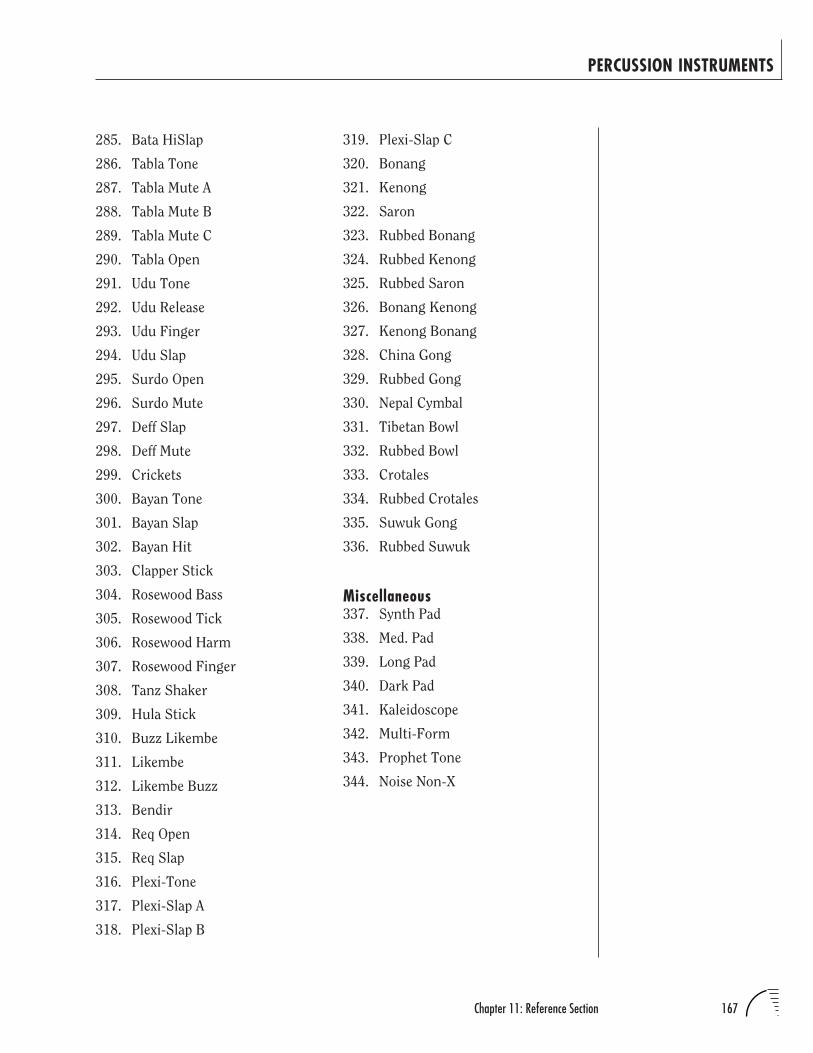
167Chapter 11: Reference Section
PERCUSSION INSTRUMENTS
285. Bata HiSlap
286. Tabla Tone
287. Tabla Mute A
288. Tabla Mute B
289. Tabla Mute C
290. Tabla Open
291. Udu Tone
292. Udu Release
293. Udu Finger
294. Udu Slap
295. Surdo Open
296. Surdo Mute
297. Deff Slap
298. Deff Mute
299. Crickets
300. Bayan Tone
301. Bayan Slap
302. Bayan Hit
303. Clapper Stick
304. Rosewood Bass
305. Rosewood Tick
306. Rosewood Harm
307. Rosewood Finger
308. Tanz Shaker
309. Hula Stick
310. Buzz Likembe
311. Likembe
312. Likembe Buzz
313. Bendir
314. Req Open
315. Req Slap
316. Plexi-Tone
317. Plexi-Slap A
318. Plexi-Slap B
319. Plexi-Slap C
320. Bonang
321. Kenong
322. Saron
323. Rubbed Bonang
324. Rubbed Kenong
325. Rubbed Saron
326. Bonang Kenong
327. Kenong Bonang
328. China Gong
329. Rubbed Gong
330. Nepal Cymbal
331. Tibetan Bowl
332. Rubbed Bowl
333. Crotales
334. Rubbed Crotales
335. Suwuk Gong
336. Rubbed Suwuk
Miscellaneous337. Synth Pad
338. Med. Pad
339. Long Pad
340. Dark Pad
341. Kaleidoscope
342. Multi-Form
343. Prophet Tone
344. Noise Non-X
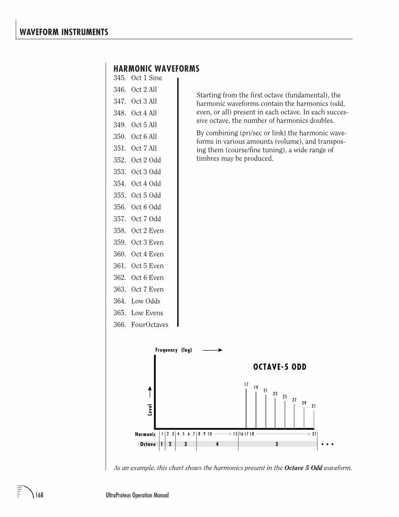
168 UltraProteus Operation Manual
WAVEFORM INSTRUMENTS
HARMONIC WAVEFORMS345. Oct 1 Sine
346. Oct 2 All
347. Oct 3 All
348. Oct 4 All
349. Oct 5 All
350. Oct 6 All
351. Oct 7 All
352. Oct 2 Odd
353. Oct 3 Odd
354. Oct 4 Odd
355. Oct 5 Odd
356. Oct 6 Odd
357. Oct 7 Odd
358. Oct 2 Even
359. Oct 3 Even
360. Oct 4 Even
361. Oct 5 Even
362. Oct 6 Even
363. Oct 7 Even
364. Low Odds
365. Low Evens
366. FourOctaves
Starting from the first octave (fundamental), the
harmonic waveforms contain the harmonics (odd,
even, or all) present in each octave. In each succes-
sive octave, the number of harmonics doubles.
By combining (pri/sec or link) the harmonic wave-
forms in various amounts (volume), and transpos-
ing them (course/fine tuning), a wide range of
timbres may be produced.
As an example, this chart shows the harmonics present in the Octave 5 Odd waveform.
1 2 3 4 5 6 7 8 9 10 15 16 17 3118
1 2 3 4 5
Harmonic
Octave
Frequency ( log)
Leve
l
1719
2123
2527
2931
OCTAVE-5 ODD
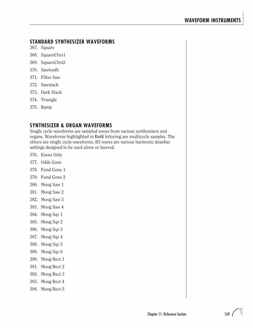
169Chapter 11: Reference Section
WAVEFORM INSTRUMENTS
STANDARD SYNTHESIZER WAVEFORMS367. Square
368. SquareChrs1
369. SquareChrs2
370. Sawtooth
371. Filter Saw
372. Sawstack
373. Dark Stack
374. Triangle
375. Ramp
SYNTHESIZER & ORGAN WAVEFORMSSingle cycle waveforms are sampled waves from various synthesizers and
organs. Waveforms highlighted in Bold lettering are multicycle samples. The
others are single cycle waveforms. B3 waves are various harmonic drawbar
settings designed to be used alone or layered.
376. Evens Only
377. Odds Gone
378. Fund Gone 1
379. Fund Gone 2
380. Moog Saw 1
381. Moog Saw 2
382. Moog Saw 3
383. Moog Saw 4
384. Moog Sqr 1
385. Moog Sqr 2
386. Moog Sqr 3
387. Moog Sqr 4
388. Moog Sqr 5
389. Moog Sqr 6
390. Moog Rect 1
391. Moog Rect 2
392. Moog Rect 3
393. Moog Rect 4
394. Moog Rect 5
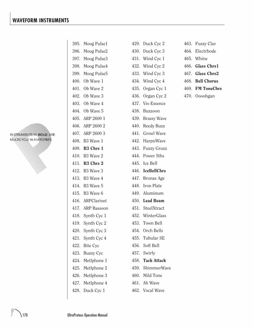
170 UltraProteus Operation Manual
WAVEFORM INSTRUMENTS
395. Moog Pulse1
396. Moog Pulse2
397. Moog Pulse3
398. Moog Pulse4
399. Moog Pulse5
400. Ob Wave 1
401. Ob Wave 2
402. Ob Wave 3
403. Ob Wave 4
404. Ob Wave 5
405. ARP 2600 1
406. ARP 2600 2
407. ARP 2600 3
408. B3 Wave 1
409. B3 Chrs 1
410. B3 Wave 2
411. B3 Chrs 2
412. B3 Wave 3
413. B3 Wave 4
414. B3 Wave 5
415. B3 Wave 6
416. ARPClarinet
417. ARP Bassoon
418. Synth Cyc 1
419. Synth Cyc 2
420. Synth Cyc 3
421. Synth Cyc 4
422. Bite Cyc
423. Buzzy Cyc
424. Metlphone 1
425. Metlphone 2
426. Metlphone 3
427. Metlphone 4
428. Duck Cyc 1
463. Fuzzy Clav
464. Electrhode
465. Whine
466. Glass Chrs1
467. Glass Chrs2
468. Bell Chorus
469. FM ToneChrs
470. Oooohgan
429. Duck Cyc 2
430. Duck Cyc 3
431. Wind Cyc 1
432. Wind Cyc 2
433. Wind Cyc 3
434. Wind Cyc 4
435. Organ Cyc 1
436. Organ Cyc 2
437. Vio Essence
438. Buzzoon
439. Brassy Wave
440. Reedy Buzz
441. Growl Wave
442. HarpsiWave
443. Fuzzy Gruzz
444. Power 5ths
445. Ice Bell
446. IceBellChrs
447. Bronze Age
448. Iron Plate
449. Aluminum
450. Lead Beam
451. SteelXtract
452. WinterGlass
453. Town Bell
454. Orch Bells
455. Tubular SE
456. Soft Bell
457. Swirly
458. Tack Attack
459. ShimmerWave
460. Mild Tone
461. Ah Wave
462. Vocal Wave
INSTRUMENTS IN BOLD AREMULTICYCLE WAVEFORMS.
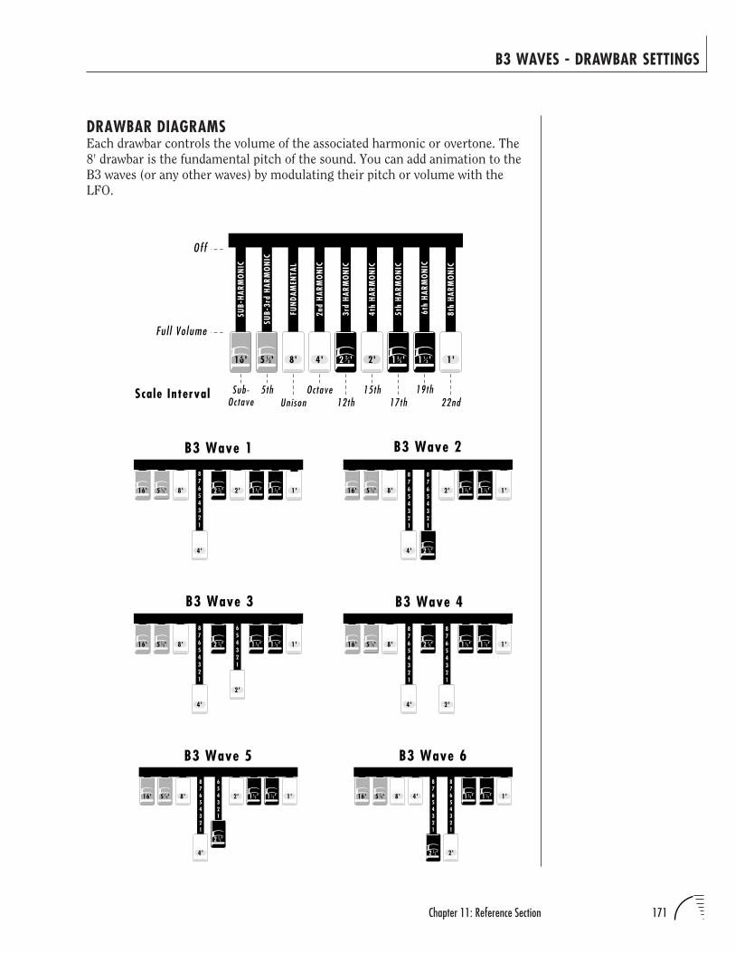
171Chapter 11: Reference Section
B3 WAVES - DRAWBAR SETTINGS
16' 8'
4'
2'
1'
B3 Wave 3
87654321
654321
2 '23 1 '1
31 '355 '1
3
87654321
87654321
16' 8'
4'
2' 1'
B3 Wave 2
5 '13 1 '1
31 '35
2 '23
16' 8'
4'
2' 1'
87654321
B3 Wave 1
5 '13 1 '1
31 '352 '2
3
8'
4' 2'
1'
B3 Wave 4
87654321
87654321
16' 1 '132 '2
3 1 '355 '1
3
16' 8'
4'
2' 1'
B3 Wave 587654321
654321
5 '13 1 '1
31 '35
2 '23
2'
B3 Wave 687654321
87654321
1'16' 8' 4'5 '13 1 '3
5 1 '13
2 '23
Scale Interval
8' 4' 2' 1'1 '132 '2
3 1 '35
SUB-
HARM
ON
IC
SUB-
3rd
HARM
ON
IC
FUN
DAM
ENTA
L
2nd
HARM
ON
IC
3rd
HARM
ON
IC
4th
HARM
ON
IC
5th
HARM
ON
IC
6th
HAR
MO
NIC
8th
HARM
ON
IC
Off
Ful l Vo lume
Sub-Octave
5thUnison
Octave12th
15th17th
19th22nd
5 '1316'
DRAWBAR DIAGRAMSEach drawbar controls the volume of the associated harmonic or overtone. The
8' drawbar is the fundamental pitch of the sound. You can add animation to the
B3 waves (or any other waves) by modulating their pitch or volume with the
LFO.
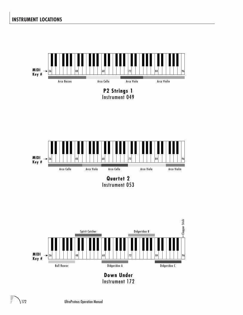
172 UltraProteus Operation Manual
INSTRUMENT LOCATIONS
Ins t rument 049P2 Strings 1
Arco Ce l lo
MIDIKey #
36 48 60 72 84 96
Arco V io laArco Basses Arco V io l in
Ins t rument 172Down Under
Bul l Roarer
MIDIKey #
Clap
per
Stic
k
36 48 60 72 84 96
Spir i t Catcher
Didger idoo A
Didger idoo B
Didger idoo C
Ins t rument 053Quartet 2
Arco Ce l lo
MIDIKey #
36 48 60 72 84 96
Arco V io la Arco Ce l lo Arco V io la Arco V io l in
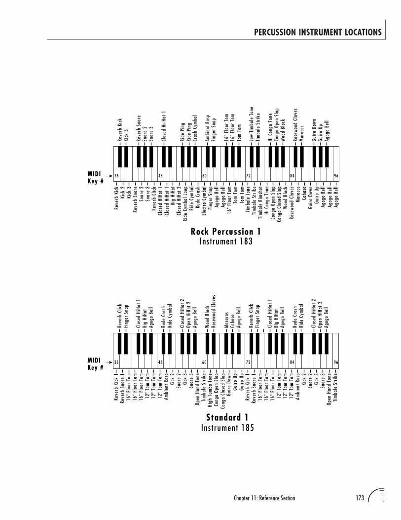
173Chapter 11: Reference Section
PERCUSSION INSTRUMENT LOCATIONS
Reve
rb K
ick
Kick
2Ki
ck 3
Reve
rb S
nare
Snar
e 2
Snar
e 3
Reve
rb C
lick
Clos
ed H
iHat
1Cl
osed
HiH
at 1
Big
HiHa
tCl
osed
HiH
at 2
Ride
Cym
bal L
oop
Ride
Cym
bal
Rud
e Cr
ash
Elec
tro
Cym
bal
Fing
er S
nap
Agog
o Be
llAg
ogo
Bell
Tim
bale
Ton
e
Hi C
onga
Ton
eCo
nga
Open
Sla
p
Woo
d Bl
ock
Mar
acas
Caba
sa
Agog
o Be
ll
16"
Floo
r To
m16
" Fl
oor
Tom
Reve
rb K
ick
Kick
3
Reve
rb S
nare
Snar
e 2
Snar
e 3
Clos
ed H
i-Hat
1
Ride
Pin
gRi
de P
ing
Cras
h Cy
mba
l
Ambi
ent R
asp
Fing
er S
nap
Tom
Tom
Tom
Tom
Tom
Tom
Low
Tim
bale
Ton
eTi
mba
le S
trik
e
Hi C
onga
Ton
eCo
nga
Open
Sla
pW
ood
Bloc
k
Rose
wood
Cla
ves
Mar
acas
Guir
o Do
wnGu
iro
Up
Agog
o Be
llAg
ogo
Bell
Agog
o Be
ll
16"
Floo
r To
m
Tim
bale
Str
ike
Tim
bale
Rim
shot
Cong
a Cl
osed
Sla
p
Rose
wood
Cla
ves
Guir
o Do
wnGu
iro
Up
MIDIKey #
36 48 60 72 84 96
Rock Percussion 1Ins t rument 183
Guir
o Do
wnGu
iro
Up
Cong
a Op
en S
lap
High
Tum
ba T
one
Tim
bale
Str
ike
Open
Han
d To
neSn
are
3Ki
ck 3
Snar
e 2
Kick
2
12"
Tom
Tom
12"
Tom
Tom
12"
Tom
Tom
16"
Floo
r To
m16
" Fl
oor
Tom
Reve
rb S
nare
1Re
verb
Kic
k 1
16"
Floo
r To
m
Reve
rb C
lick
Clos
ed H
iHat
1Bi
g Hi
Hat
Clos
ed H
iHat
2Op
en H
iHat
2
Ride
Cym
bal
Rude
Cra
sh
Agog
o Be
ll
Fing
er S
nap
Woo
d Bl
ock
Mar
acas
Caba
saAg
ogo
Bell
Rose
wood
Cla
ves
Ambi
ent R
asp
Cong
a Cl
osed
Sla
p
Guir
o Up
Agog
o Be
ll
Tim
bale
Str
ike
Open
Han
d To
neSn
are
3Ki
ck 3
Snar
e 2
Kick
2
12"
Tom
Tom
12"
Tom
Tom
12"
Tom
Tom
16"
Floo
r To
m16
" Fl
oor
Tom
Reve
rb S
nare
1Re
verb
Kic
k 1
16"
Floo
r To
m
Ambi
ent R
asp
Reve
rb C
lick
Clos
ed H
iHat
1Bi
g Hi
Hat
Clos
ed H
iHat
2Op
en H
iHat
2
Ride
Cym
bal
Rude
Cra
sh
Agog
o Be
ll
Fing
er S
nap
Agog
o Be
ll
Standard 1
MIDIKey #
36 48 60 72 84 96
Ins t rument 185
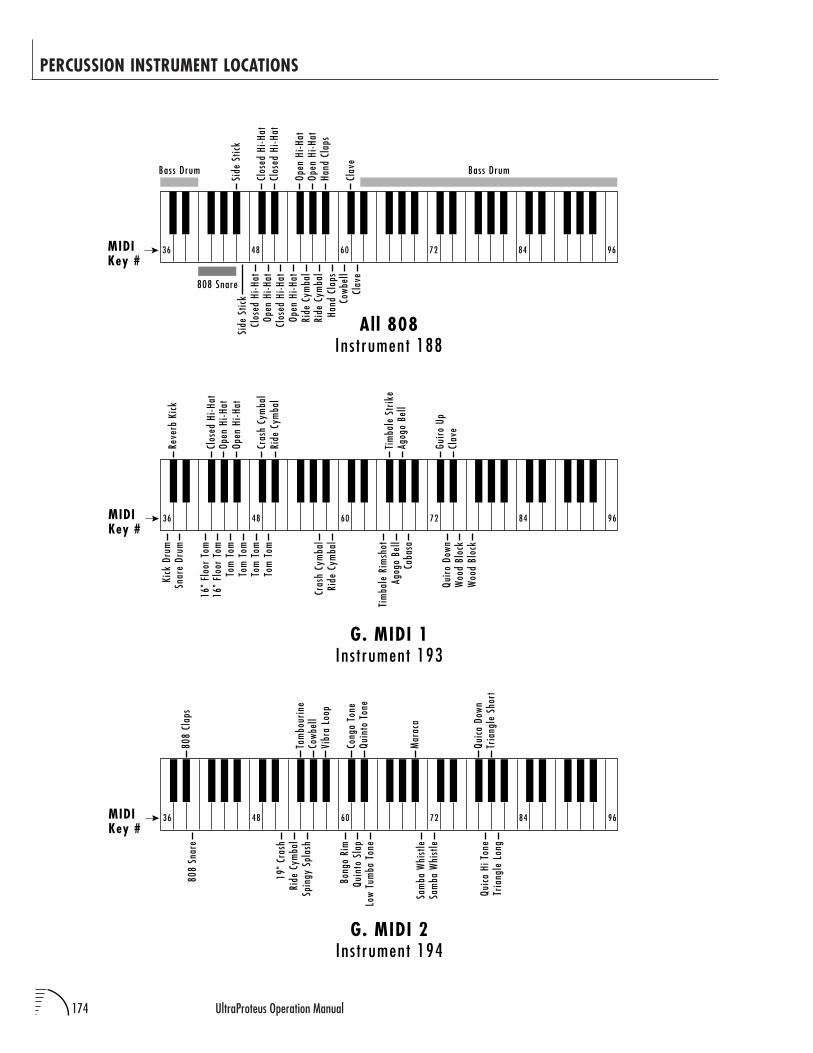
174 UltraProteus Operation Manual
PERCUSSION INSTRUMENT LOCATIONS
Ins t rument 188All 808
Bass Drum Bass Drum
Side
Stic
kCl
osed
Hi-H
at
Clos
ed H
i-Hat
Open
Hi-H
at
Open
Hi-H
atRi
de C
ymba
lRi
de C
ymba
lHa
nd C
laps
Cowb
ell
Clav
e
808 Snare
MIDIKey #
Side
Stic
k
Clos
ed H
i-Hat
Clos
ed H
i-Hat
Open
Hi-H
atOp
en H
i-Hat
Hand
Cla
ps
Clav
e
36 48 60 72 84 96
Ins t rument 194G. MIDI 2
808
Snar
e
19"
Cras
hRi
de C
ymba
lSp
ingy
Spl
ash
Bong
o Ri
mQu
into
Sla
pLo
w Tu
mba
Ton
e
Sam
ba W
hist
leSa
mba
Whi
stle
Quic
a Hi
Ton
eTr
iang
le L
ong
MIDIKey #
808
Clap
s
Tam
bour
ine
Cowb
ell
Vibr
a Lo
op
Cong
a To
neQu
into
Ton
e
Mar
aca
Quic
a Do
wnTr
iang
le S
hort
36 48 60 72 84 96
Ins t rument 193G. MIDI 1
Kick
Dru
mSn
are
Drum
16"
Floo
r To
m16
" Fl
oor
Tom
Tom
Tom
Tom
Tom
Tom
Tom
Tom
Tom
Cras
h Cy
mba
lRi
de C
ymba
l
Tim
bale
Rim
shot
Agog
o Be
llCa
basa
Quir
o Do
wnW
ood
Bloc
kW
ood
Bloc
k
MIDIKey #
Reve
rb K
ick
Clos
ed H
i-Hat
Open
Hi-H
atOp
en H
i-Hat
Cras
h Cy
mba
lRi
de C
ymba
l
Agog
o Be
ll
Guir
o Up
Clav
e
Tim
bale
Str
ike
36 48 60 72 84 96
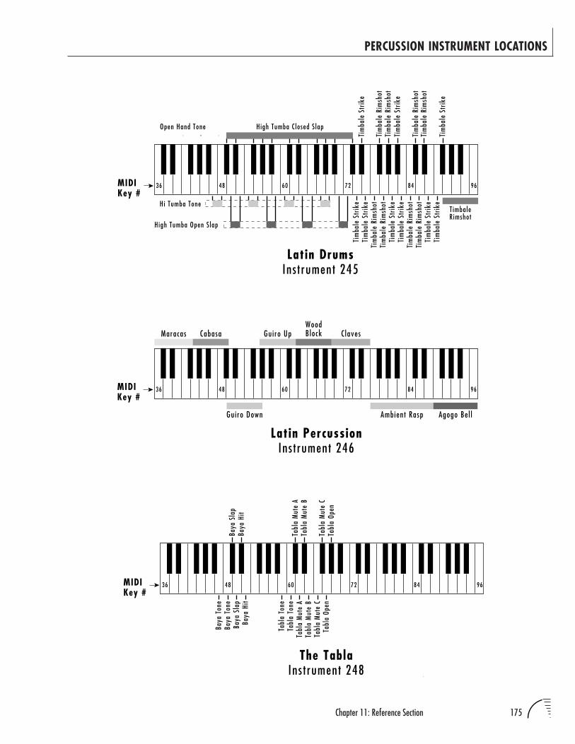
175Chapter 11: Reference Section
PERCUSSION INSTRUMENT LOCATIONS
Ins t rument 245Latin Drums
Tim
bale
Rim
shot
Tim
bale
Str
ike
Tim
bale
Rim
shot
Tim
bale
Str
ike
H igh Tumba C losed S lap
Hi Tumba Tone
High Tumba Open S lap
Tim
bale
Str
ike
Tim
bale
Str
ike
Tim
bale
Rim
shot
Tim
bale
Str
ike
Tim
bale
Str
ike
Tim
bale
Rim
shot
Tim
bale
Str
ike
Tim
bale
Rim
shot
Tim
bale
Rim
shot
Tim
bale
Str
ike
Tim
bale
Rim
shot
Tim
bale
Rim
shot
Tim
bale
Str
ike
T imbaleRimshot
Open Hand Tone
MIDIKey #
36 48 60 72 84 96
Ins t rument 248The Tabla
Baya
Ton
e
MIDIKey #
36 48 60 72 84 96
Baya
Sla
pBa
ya H
it
Tabl
a M
ute
ATa
bla
Tone
Tabl
a M
ute
BTa
bla
Mut
e C
Tabl
a Op
en
Baya
Sla
p
Baya
Ton
e
Baya
Hit
Tabl
a M
ute
ATa
bla
Mut
e B
Tabl
a M
ute
CTa
bla
Open
Tabl
a To
ne
Latin PercussionGuiro Down
Claves
Ambient Rasp Agogo Bel l
WoodBlockGuiro UpCabasaMaracas
MIDIKey #
36 48 60 72 84 96
Ins t rument 246
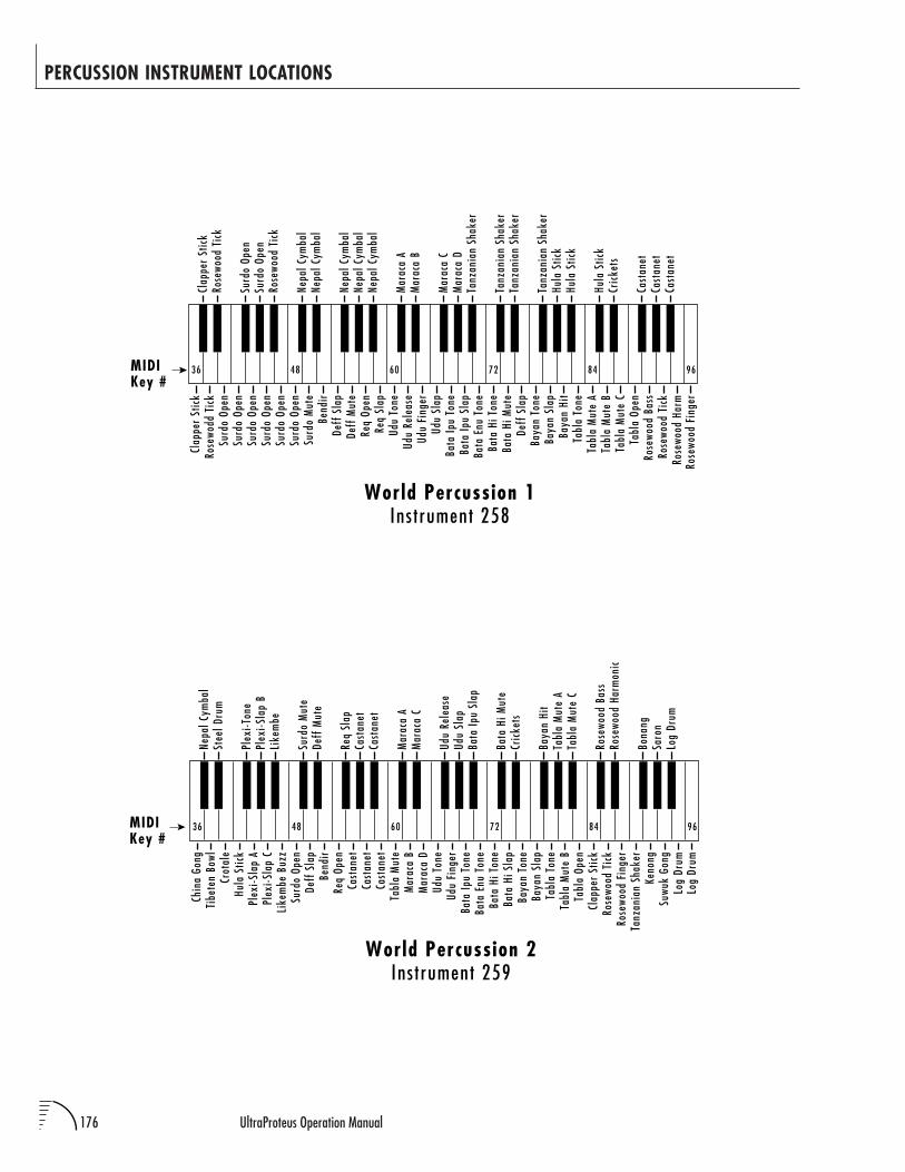
176 UltraProteus Operation Manual
PERCUSSION INSTRUMENT LOCATIONS
Hula
Stic
kPl
exi-S
lap
APl
exi-S
lap
CLi
kem
be B
uzz
Surd
o Op
en
Tanz
ania
n Sh
aker
Clap
per
Stic
k
I n s t rument 259World Percussion 2
Chin
a Go
ng
MIDIKey #
Nepa
l Cym
bal
Tibe
ten
Bowl
Stee
l Dru
m
36 48 60 72 84 96
Plex
i-Ton
ePl
exi-S
lap
BLi
kem
be
Surd
o M
ute
Deff
Mut
e
Req
Slap
Cast
anet
Cast
anet
Deff
Sla
pBe
ndir
Req
Open
Cast
anet
Cast
anet
Cast
anet
Mar
aca
AM
arac
a C
Tabl
a M
ute
Mar
aca
BM
arac
a D
Udu
Tone
Udu
Rele
ase
Udu
Slap
Bata
Ipu
Slap
Udu
Fing
erBa
ta Ip
u To
neBa
ta E
nu T
one
Bata
Hi T
one
Bata
Hi S
lap
Baya
n To
ne
Bata
Hi M
ute
Cric
kets
Baya
n Hi
tBa
yan
Slap
Tabl
a To
neTa
bla
Mut
e B
Tabl
a M
ute
ATa
bla
Mut
e C
Tabl
a Op
en
Rose
wood
Tic
kRo
sewo
od F
inge
r
Keno
ngSu
wuk
Gong
Log
Drum
Log
Drum
Rose
wood
Bas
sRo
sewo
od H
arm
onic
Bona
ngSa
ron
Log
Drum
Crot
ale
Surd
o Op
enSu
rdo
Open
Surd
o Op
enSu
rdo
Open
Surd
o Op
en
Tabl
a Op
en
Tabl
a M
ute
A
I n s t rument 258World Percussion 1
Clap
per
Stic
k
MIDIKey #
Clap
per
Stic
kRo
sewo
dd T
ick
Rose
wood
Tic
k
36 48 60 72 84 96
Surd
o Op
enSu
rdo
Open
Rose
wood
Tic
k
Nepa
l Cym
bal
Nepa
l Cym
bal
Nepa
l Cym
bal
Nepa
l Cym
bal
Nepa
l Cym
bal
Surd
o M
ute
Bend
irDe
ff S
lap
Deff
Mut
eRe
q Op
enRe
q Sl
ap
Mar
aca
AM
arac
a B
Udu
Tone
Udu
Rele
ase
Udu
Fing
erUd
u Sl
apM
arac
a C
Mar
aca
DTa
nzan
ian
Shak
er
Bata
Ipu
Tone
Bata
Ipu
Slap
Bata
Enu
Ton
eBa
ta H
i Ton
eBa
ta H
i Mut
eDe
ff S
lap
Tanz
ania
n Sh
aker
Tanz
ania
n Sh
aker
Tanz
ania
n Sh
aker
Baya
n To
neBa
yan
Slap
Baya
n Hi
tHu
la S
tick
Hula
Stic
kTa
bla
Tone
Tabl
a M
ute
BTa
bla
Mut
e C
Rose
wood
Bas
sRo
sewo
od T
ick
Rose
wood
Har
mRo
sewo
od F
inge
r
Hula
Stic
kCr
icke
ts
Cast
anet
Cast
anet
Cast
anet
Surd
o Op
en
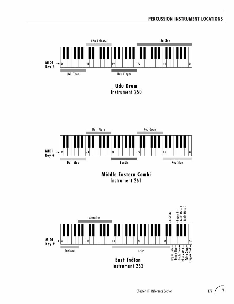
177Chapter 11: Reference Section
PERCUSSION INSTRUMENT LOCATIONS
Udu Drum
Udu Tone Udu F inger
Udu S lapUdu Release
MIDIKey #
36 48 60 72 84 96
Ins t rument 250
Ins trument 262East Indian Ba
yan
ToneTambura
MIDIKey #
Cric
kets
36 48 60 72 84 96
Accord ion
Si tar
Baya
n Hi
tBa
yan
Slap
Tabl
a To
neTa
bla
Mut
e A
Tabl
a M
ute
BTa
bla
Mut
e C
Tabl
a Op
enCl
appe
r St
ick
Middle Eastern Combi
Deff S lap Bendir Req S lap
Req OpenDeff Mute
MIDIKey #
36 48 60 72 84 96
Ins t rument 261
178 UltraProteus Operation Manual
Z-PLANE FILTER DESCRIPTIONS
The Z-Plane filters are categorized into groups of: Flangers, Vowel Filters,
Traditional Filters, Parametric Filters, Instrument Models, etc. A suffix of ‘4’ or
‘.4’ indicates filter is square, not cube and does not contain a Transform 2 axis.
FLANGERSMembers of this filter family contain a series of notches with various depths,
widths and frequencies. The traditional flange effect is created by sweeping
different frequency notches with a real time controller. Another application for
flangers is enhanced dynamic expression at note-on by using velocity to modu-
late the frequencies of the notches and overall cut-off. These filters can simulate
different pick positions on guitar strings and various locations of drum, mallet
and cymbal strikes, etc.
F000 Null Filter
F001 Low Pass Flange .4Morph: Starts with high end roll-off and deep, narrow notches at500Hz, 100Hz, 200Hz, 400Hz and 800Hz and transforms into lessdeep, wider notches at 11799Hz, 13813Hz, 16169Hz, 17495Hz and18928Hz with no roll-off.
Freq. Tracking: Moves the notches in the first frame of the Morph axisup two octaves. The second frame is completely flat. Tracks filter tokeyboard frequencies with Note-on key assignment. Frequency Track-ing controls brightness.
Transform 2: Not used.
F002 Low Pass Flange Bk .4A series of deep notches spaced at octave intervals morphing to less severe,more closely clustered high frequency notches. An additional lowpass filteris at the start of the Morph, opening as the maximum offset is reached.
Morph: Modulate this to create multi-flanging effects.
Freq. Tracking: Tracks flangers across the keyboard. Velocity controlsbrightness.
Transform 2: Not used.
F003 Flange 2 .4This flanger has a series of 6 notches placed at octaves, not linearly. Frame1 starts with notches at 50, 100, 200, 400, 800, and 1600Hz.
Morph: Moves all of the notches up in frequency to above 10kHz, withdecreasing depth. This means that the deepest flanging effect isobtained in the first 1/3 to 1/2 of the Morph parameter range. Notethat deep notches can cut out the fundamental of a sound whichmight decrease the volume of the note.
Freq. Tracking: Moves the notches to 400, 800, 1600, 3200, 6400,12800Hz, which allows key tracking to keep the “sweet spot” of theflanger centered over the harmonics of the note.
Transform 2: Not used.
179Chapter 11: Reference Section
Z-PLANE FILTER DESCRIPTIONS
F004 CubeFlangerA flanging filter featuring deep notches tuned in octaves and a steep roll-offof high frequencies when all axes have no offset. High settings for Trans-form 2 can produce some rather metallic-sounding overtones. Apart fromflanging effects, this filter can be used in much the same way as a standardresonant synth filter.
Morph: Tunes the filter notches.
Freq. Tracking: Controls lowpass filter cutoff point.
Transform 2: Increases resonance and introduces some peaks.
F005 Flange3.4
Notches are spaced at a ratio of 1.61 between notch frequencies, starting at40Hz. This spacing means that notches will not fall on top of all of theharmonics of a sound at once. Instead, they should hit harmonics one at atime as they are swept in frequency. Traditional flangers have notchesspaced linearly, not log spaced.
Morph: Moves all of the notches up above 10kHz, with the relativefrequency spacing decreasing. The deepest flange effect will happen inthe lower 1/3 to 1/5 of the morph parameter range.
Freq. Tracking: Sets the initial tuning of the notches, moving all of thenotches up from 40Hz to 325Hz as the base frequency.
Transform 2: Not used.
F006 Flange 4.4
A highly resonant flanger /filter type. Sweeping the Morph axis producesdramatic effects. The Filter Frequency Track parameter can be used to tunethe flanger; higher values produce more open sounds.
Morph: Increase to raise the cutoff frequency and vary the gain of thevarious peaks and notches.
Freq. Tracking: Tunes the filter.
Transform 2: Not used.
F007 Flange 5
A complex flange possessing some vocal-sounding characteristics. Sweep-ing along the Morph or Freq. Track axes produce flanger-like effects.
Morph: Tunes the notches.
Freq. Tracking: Spreads the notches.
Transform 2: Increase this to move the filter toward a more flat curve.
F008 Flange 6.4
Introduces both peaks and notches which start widely spaced and becomemore tightly distributed as Morph Offset reaches maximum. The centerfrequencies for the various filter bands move towards higher ranges as theMorph or Filter Freq. Track parameters are swept upward; the effect is notunlike a sweeping of multiple resonant band-pass filters.
180 UltraProteus Operation Manual
Z-PLANE FILTER DESCRIPTIONS
F009 Flange 6R.4This is a variation of filter 008, Flange 6.4. It is a bit more resonant-sounding, due in part to higher ‘Q’ settings. Sweeping the Morph axis canproduce the syllable ‘yi’.
Morph: Sweep filter frequency bands up and together when modulatedin a positive direction.
Freq. Tracking: Sweep filter frequency bands up and together whenmodulated in a positive direction.
Transform 2: Not used.
F010 Flanger 7.4
A series of harmonically related notches is moved from the lower-midrangeto the upper-midrange as this filter is moved along the Frequency Trackingaxis. Morphing brings in the flanging effect
Morph: Use this to sweep the notches.
Freq. Tracking: Use this to tune the notches.
Transform 2: Not used.
F011 BriteFlnge.4
A series of notches, tuned in octaves, are swept upward and finally convergeat 19.5kHz as this filter is pushed up along the Morph axis. A small bump atabout 15kHz is introduced to maintain brightness when Morph is atcompletely offset.
Morph: Increasing this value sweeps the filter notches upward andtogether.
Freq. Tracking: Increasing this raises the lowpass filter cutoff point.
Transform 2: Not used.
F012 Flng>Flng1Morph: Sweeps from flange 1 to flange 2
Freq. Tracking: Provides key tracking to maintain spectrum.
Transform 2: Provides volume and brightness control with velocityand/or key position
Comments: Key tracking enhances the depth of the flange. Try addingvelocity to Frequency Tracking for more “Fun”.
F013 0>Flng2Morph: Reveals flat to flange filter
Freq. Tracking: Provides key tracking to maintain spectrum
Transform 2: Adds volume, different flange
Comments: Nice for introducing a subtle flange to a pure sound.Velocity has a natural effect increasing flange depth, volume andbrightness.
181Chapter 11: Reference Section
Z-PLANE FILTER DESCRIPTIONS
F014 Flng>Flng3bMorph: Sweeps from flange 1 to 2
Freq. Tracking: Provides key tracking to enhance flanging
Transform 2: Increases depth of flange
Comments: A gentle sweeper.
F015 Flng>Flng4Morph: Sweeps flange
Freq. Tracking: Provides key tracking to enhance flanging.
Transform 2: Reduces depth of flange effect with Morph offset, other-wise, increases flange depth.
F016 Flng>Flng5Morph: Sweeps from flange 1 to 2
Freq. Tracking: Provides key tracking to enhance flanging.
Transform 2: Increases depth of flange, more bell-like.
Comments: Morphing sweeps gently, but Transform 2 adds more depthand introduces a bell-like quality to the flange.
F017 Flng>Flng6Morph: Sweeps from flange 1 to 2.
Freq. Tracking: Provides key tracking to fix partials.
Transform 2: Provides more brightness and flange.
F018 Flng>FlngTMorph: Sweeps between flat and flange.
Freq. Tracking: Provides key tracking to fix partials.
Transform 2: Provides more brightness and flange.
Comments: A gentle-touch flanger. Low Transform 2 gives a softchorus on morphing. Higher Transform 2 gives exaggerated depth.
F019 Flng>FlngCMorph: Sweeps from open to closed response with all other axes at 0.
Freq. Tracking: Controls brightness.
Transform 2: Adds extra flange.
F020 CO>FlngTMorph: Sweeps from a reveal (almost flat) point to low pass peaks
Freq. Tracking: Raises frequency of peaks.
Transform 2: Increases depth of flange.
182 UltraProteus Operation Manual
Z-PLANE FILTER DESCRIPTIONS
DIPTHONGSImplemented with parametric equalizer subsections, the resonances do not
have the traditional overall lowpass effect that a true vocal resonance would
have. Instead, they are placed at the same frequency as the resonances would be
found in a true vowel, but the response at high frequencies is essentially flat to
allow high frequencies of the samples to get through the filter.
The Morph axis controls movement between vowels. Key tracking is controlled
by Frequency Tracking. Brightness and depth of effect is controlled by Trans-
form 2. In certain filters, brightness is controlled by assigning velocity to
Frequency Tracking. Each paravowel ‘A’ contains peaks at 800 1150, 2800, 3500
and 4950Hz. Each paravowel ‘E’ contains peaks at 400, 1600, 2700, 3300 and
4900Hz. Each ‘O’ has peaks at 450, 800, 2830, 3500 and 4950Hz. Each ‘U’ has
peaks at 325, 700, 2530, 3500 and 4950Hz.
F021 AEParLPVow
This paravowel has a low pass filter to provide additional roll off, whendesired. Otherwise, it behave as the other paravowels.
Morph: Controls movement between vowels. Try setting Transform 2 to255 for additional brightness.
Freq. Tracking: Shifts all of the resonances up in frequency.
Transform 2: Controls volume, depth of effect.
F022 AEParaVowelMorph: Controls movement between vowels. Try setting Transform 2 to255.
Freq. Tracking: Shifts all of the resonances up in frequency.
Transform 2: Controls the amplitude of all of the resonances, with 000providing the lowest resonance amplitude, and 256 providing thehighest resonance amplitude.
F023 AOLpParaVow
This paravowel has a low pass filter to provide additional roll off, whendesired. Otherwise, it behaves as the other paravowels.
Morph: Controls movement between vowels. Try setting Transform 2 to255.
Freq. Tracking: Shifts all of the resonances up in frequency.
Transform 2: Controls the amplitude of all of the resonances.
F024 AOParaVowelMorph: Controls movement between vowels.
Freq. Tracking: Shifts all of the resonances up in frequency.
Transform 2: Controls the amplitude of all of the resonances.
183Chapter 11: Reference Section
Z-PLANE FILTER DESCRIPTIONS
F025 AUParaVow.4Morph: Controls movement between vowels.
Freq. Tracking: Shifts all of the resonances up in frequency.
Transform 2: Controls the amplitude of all of the resonances.
F026 UOParaVow.4Morph: Controls movement between vowels.
Freq. Tracking: Shifts all of the resonances up in frequency.
Transform 2: Controls the amplitude of all of the resonances.
F027 SftEOVowel4Morph: Controls movement between vowels.
Freq. Tracking: Shifts all of the resonances up in frequency.
Transform 2: Controls the amplitude of all of the resonances.
F028 SoftEOAEMorph: Controls movement between vowels.
Freq. Tracking: Shifts all of the resonances up in frequency.
Transform 2: Controls the amplitude of all of the resonances.
F029 Vocal CubeMorph: Sweeps frequencies.
Freq. Tracking: Assign to velocity for brightness control.
Transform 2: Tunes filter.
F030 C1-6 Harms4Morph: Sweeps between a notch at 190Hz to a series of closely spacedpeaks from 120Hz to 640Hz
Freq. Tracking: Tracks filter with keyboard. Try assigning velocity toFrequency Tracking for brightness control.
Transform 2: Not used.
F031 Voce.4Morph: Controls movement between ‘oo’ and ‘ee’.
Freq. Tracking: Designed for velocity control of brightness. (Transformsto frequencies two octaves higher.)
Transform 2: Not used.
F032 ChoralComb4Morph: Sweeps between different frequency notches tuned for vocalformants.
Freq. Tracking: Tracks filter with keyboard range.
Transform 2: Not used.
184 UltraProteus Operation Manual
Z-PLANE FILTER DESCRIPTIONS
F033 Bassutoi.4Morph: Controls movement between ‘yu’ and ‘ee’.
Freq. Tracking: Tracks filter with keyboard range and controlsbrightness with velocity assigned.
Transform 2: Not used.
F034 Be Ye.4
Designed to say ‘Be Ye’.
Morph: Sweeps vocal formants.
Freq. Tracking: Tracks filter with keyboard range and controls bright-ness with velocity assigned.
Transform 2: Not used.
F035 Ee-Yi.4Morph: Controls movement between vowels ‘e’ and ‘i’.
Freq. Tracking: Tracks filter with keyboard range and controls bright-ness with velocity assigned.
Transform 2: Not used.
F036 Ii-Yi.4Morph: Controls movement between vowels.
Freq. Tracking: Tracks filter with keyboard range and controls bright-ness with velocity assigned.
Transform 2: Not used.
F037 Uhrrrah.4Morph: Roars like a lion.
Freq. Tracking: Tracks filter with keyboard range and controls bright-ness with velocity assigned.
Transform 2: Not used.
F038 YeahYeah.4See “What Yeah” preset.
Morph: Moves between ‘ee’ and ‘ya’ sounds.
Freq. Tracking: Tracks filter with keyboard range and controls bright-ness when assigned to velocity.
Transform 2: Not used.
F039 Vow>Vow1Morph: Sweeps between ‘ah’ and ‘oh’.
Freq. Tracking: Provides key tracking to balance keyboard brightness.
Transform 2: Provides volume and brightness control with velocityand/or key position.
Comments: Transform 2 increases volume and depth of vowel effect.
185Chapter 11: Reference Section
Z-PLANE FILTER DESCRIPTIONS
F040 Vow>Vow2Morph: Sweeps between ‘ee’ and ‘oh’.
Freq. Tracking: Provides key tracking to fix partials.
Transform 2: Provides volume and brightness control with velocityand/or key position.
Comments: Morphing sweeps between vowels- slight ‘E’ effect.
F041 YahYahs.4Morph: Sweeps between ‘eeya’ and ‘aa’.
Freq. Tracking: Introduces frequencies two octaves higher for keytracking and brightness control.
Transform 2: Not used.
F042 YoYo.4Morph: Sweeps between ‘ee’ and ‘oh’ sounds.
Freq. Tracking: Introduces frequencies two octaves higher for keytracking and brightness control.
Transform 2: Not used.
F043 VowelSpace
Dr. William Martens developed this filter cube, which allows any vowel tobe approximated with only two parameters.
Morph: Sweeps the first formant of the vowel from 150Hz up to850Hz.
Freq. Tracking: Sweeps the second formant from 500Hz up to 2500Hz.
Transform 2: Changes the vowel “stress.” Low stress means that all ofthe vowel frequencies collapse to a relaxed “schwa” sound. MaximumTransform produces the maximum excursion (stress) for all of thevowel frequencies.
STANDARDThese filters are variations on traditional 2 and 4-pole filter models
F044 BrickWaLP.4
This filter features an extreme rolloff at the cutoff point, which moves from100Hz to 3000Hz. Use this filter to produce low-resonance filter sweeps, orto selectively filter out high frequencies in the source sound.
Morph: Controls filter cutoff.
Freq. Tracking: Controls filter depth and provides gentler roll-offbeginning ≈3000Hz.
Transform 2: Not used.
A “BRICKWALL” FILTER IS ONEWITH AN EXTREMELY STEEPSLOPE.
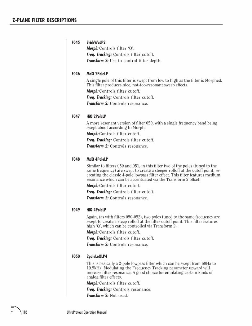
186 UltraProteus Operation Manual
Z-PLANE FILTER DESCRIPTIONS
F045 BrickWaLP2Morph: Controls filter ‘Q’.
Freq. Tracking: Controls filter cutoff.
Transform 2: Use to control filter depth.
F046 MdQ 2PoleLPA single pole of this filter is swept from low to high as the filter is Morphed.This filter produces nice, not-too-resonant sweep effects.
Morph: Controls filter cutoff.
Freq. Tracking: Controls filter cutoff.
Transform 2: Controls resonance.
F047 HiQ 2PoleLPA more resonant version of filter 050, with a single frequency band beingswept about according to Morph.
Morph: Controls filter cutoff.
Freq. Tracking: Controls filter cutoff.
Transform 2: Controls resonance .
F048 MdQ 4PoleLPSimilar to filters 050 and 051, in this filter two of the poles (tuned to thesame frequency) are swept to create a steeper rolloff at the cutoff point, re-creating the classic 4-pole lowpass filter effect. This filter features mediumresonance which can be accentuated via the Transform 2 offset.
Morph: Controls filter cutoff.
Freq. Tracking: Controls filter cutoff.
Transform 2: Controls resonance.
F049 HiQ 4PoleLP
Again, (as with filters 050-052), two poles tuned to the same frequency areswept to create a steep rolloff at the filter cutoff point. This filter featureshigh ‘Q’, which can be controlled via Transform 2.
Morph: Controls filter cutoff.
Freq. Tracking: Controls filter cutoff.
Transform 2: Controls resonance.
F050 2poleLoQLP4
This is basically a 2-pole lowpass filter which can be swept from 60Hz to19.5kHz. Modulating the Frequency Tracking parameter upward willincrease filter resonance. A good choice for emulating certain kinds ofanalog filter effects.
Morph: Controls filter cutoff.
Freq. Tracking: Controls resonance.
Transform 2: Not used.
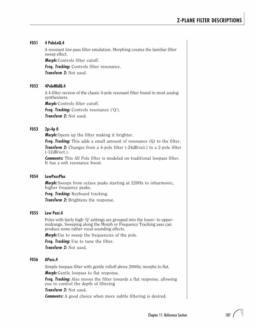
187Chapter 11: Reference Section
Z-PLANE FILTER DESCRIPTIONS
F051 4 PoleLoQ.4A resonant low-pass filter emulation. Morphing creates the familiar filtersweep effect.
Morph: Controls filter cutoff.
Freq. Tracking: Controls filter resonance.
Transform 2: Not used.
F052 4PoleMidQ.4A 4-filter version of the classic 4-pole resonant filter found in most analogsynthesizers.
Morph: Controls filter cutoff.
Freq. Tracking: Controls resonance (‘Q’).
Transform 2: Not used.
F053 2p>4p 0Morph: Opens up the filter making it brighter.
Freq. Tracking: This adds a small amount of resonance (Q) to the filter.
Transform 2: Changes from a 4-pole filter (-24dB/oct.) to a 2-pole filter(-12dB/oct.).
Comments: This All Pole filter is modeled on traditional lowpass filter.It has a soft resonance boost.
F054 LowPassPlusMorph: Sweeps from octave peaks starting at 220Hz to inharmonic,higher frequency peaks.
Freq. Tracking: Keyboard tracking.
Transform 2: Brightens the response.
F055 Low Past.4Poles with fairly high ‘Q’ settings are grouped into the lower- to upper-midrange. Sweeping along the Morph or Frequency Tracking axes canproduce some rather vocal-sounding effects.
Morph: Use to sweep the frequencies of the pole.
Freq. Tracking: Use to tune the filter.
Transform 2: Not used.
F056 APass.4
Simple lowpass filter with gentle rolloff above 200Hz; morphs to flat.
Morph: Gentle lowpass to flat response.
Freq. Tracking: Also moves the filter towards a flat response, allowingyou to control the depth of filtering
Transform 2: Not used.
Comments: A good choice when more subtle filtering is desired.
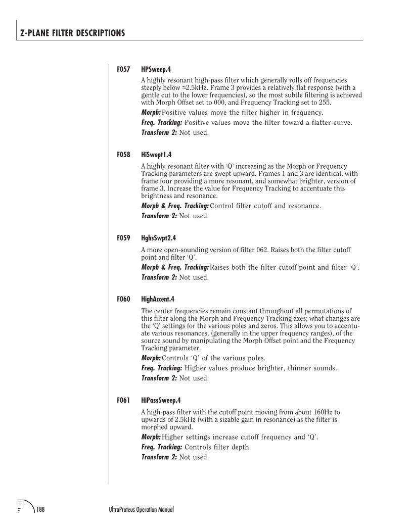
188 UltraProteus Operation Manual
Z-PLANE FILTER DESCRIPTIONS
F057 HPSweep.4A highly resonant high-pass filter which generally rolls off frequenciessteeply below ≈2.5kHz. Frame 3 provides a relatively flat response (with agentle cut to the lower frequencies), so the most subtle filtering is achievedwith Morph Offset set to 000, and Frequency Tracking set to 255.
Morph: Positive values move the filter higher in frequency.
Freq. Tracking: Positive values move the filter toward a flatter curve.
Transform 2: Not used.
F058 HiSwept1.4
A highly resonant filter with ‘Q’ increasing as the Morph or FrequencyTracking parameters are swept upward. Frames 1 and 3 are identical, withframe four providing a more resonant, and somewhat brighter, version offrame 3. Increase the value for Frequency Tracking to accentuate thisbrightness and resonance.
Morph & Freq. Tracking: Control filter cutoff and resonance.
Transform 2: Not used.
F059 HghsSwpt2.4
A more open-sounding version of filter 062. Raises both the filter cutoffpoint and filter ‘Q’.
Morph & Freq. Tracking: Raises both the filter cutoff point and filter ‘Q’.
Transform 2: Not used.
F060 HighAccent.4
The center frequencies remain constant throughout all permutations ofthis filter along the Morph and Frequency Tracking axes; what changes arethe ‘Q’ settings for the various poles and zeros. This allows you to accentu-ate various resonances, (generally in the upper frequency ranges), of thesource sound by manipulating the Morph Offset point and the FrequencyTracking parameter.
Morph: Controls ‘Q’ of the various poles.
Freq. Tracking: Higher values produce brighter, thinner sounds.
Transform 2: Not used.
F061 HiPassSweep.4
A high-pass filter with the cutoff point moving from about 160Hz toupwards of 2.5kHz (with a sizable gain in resonance) as the filter ismorphed upward.
Morph: Higher settings increase cutoff frequency and ‘Q’.
Freq. Tracking: Controls filter depth.
Transform 2: Not used.
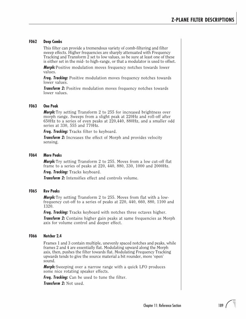
189Chapter 11: Reference Section
Z-PLANE FILTER DESCRIPTIONS
F062 Deep CombsThis filter can provide a tremendous variety of comb-filtering and filtersweep effects. Higher frequencies are sharply attenuated with FrequencyTracking and Transform 2 set to low values, so be sure at least one of theseis either set in the mid- to high-range, or that a modulator is used to offset.
Morph: Positive modulation moves frequency notches towards lowervalues.
Freq. Tracking: Positive modulation moves frequency notches towardslower values.
Transform 2: Positive modulation moves frequency notches towardslower values.
F063 One PeakMorph: Try setting Transform 2 to 255 for increased brightness overmorph range. Sweeps from a slight peak at 220Hz and roll-off after650Hz to a series of even peaks at 220,440, 880Hz, and a smaller oddseries at 330, 555 and 770Hz.
Freq. Tracking: Tracks filter to keyboard.
Transform 2: Increases the effect of Morph and provides velocitysensing.
F064 More PeaksMorph: Try setting Transform 2 to 255. Moves from a low cut-off flatframe to a series of peaks at 220, 440, 880, 330, 1000 and 2000Hz.
Freq. Tracking: Tracks keyboard.
Transform 2: Intensifies effect and controls volume.
F065 Rev PeaksMorph: Try setting Transform 2 to 255. Moves from flat with a low-frequency cut-off to a series of peaks at 220, 440, 660, 880, 1100 and1320.
Freq. Tracking: Tracks keyboard with notches three octaves higher.
Transform 2: Contains higher gain peaks at same frequencies as Morphaxis for volume control and deeper effect.
F066 Notcher 2.4
Frames 1 and 3 contain multiple, unevenly spaced notches and peaks, whileframes 2 and 4 are essentially flat. Modulating upward along the Morphaxis, then, pushes the filter towards flat. Modulating Frequency Trackingupwards tends to give the source material a bit rounder, more ‘open’sound.
Morph: Sweeping over a narrow range with a quick LFO producessome nice rotating speaker effects.
Freq. Tracking: Can be used to tune the filter.
Transform 2: Not used.
190 UltraProteus Operation Manual
Z-PLANE FILTER DESCRIPTIONS
F067 Ntches2Oct4
This filter is composed of a series of notches, tuned in octaves.
Morph & Freq. Tracking: Moves notches lower in frequency.
Transform 2: Not used.
Comments: Maximum shift is two octaves along either axis, for acombined total of four octaves if both axes are modulated.
F068 Odd>+Morph: Changes from odd to even harmonics.
Freq. Tracking: Provides key tracking to maintain spectrum.
Transform 2: Provides volume and brightness control.
Comments: Hints at odd harmonics which are then changed into adifferent shape depending on the position of Transform 2.(Transform 2 mostly respects natural changes in brightness, how-ever.)
F069 VarSlope.4
A low-pass filter in which the rolloff above the cutoff point (400Hz) be-comes steeper as the value for Morph Offset is increased.
Morph: Changes the slope of the rolloff.
Freq. Tracking: Moves the filter toward flat response.
Transform 2: Not used.
Comments: A good choice when more subtle filtering is desired.
EQUALIZATION FILTERSMost of these filters are variations of traditional parametric EQ filters.
F070 BassEQ 1.4Morph: Contains deep notch at 196Hz, morphing to a slight bump at132Hz and a dip at 2600Hz.
Freq. Tracking: Frequency Tracking opens filter completely at maxi-mum offset.
Transform 2: Not used.
F071 B BOOST.4Morph: Boosts frequencies around 60Hz, sweeping to open response.
Freq. Tracking: Provides gentle rise at 320Hz and 5kHz.
Transform 2: Not used.
191Chapter 11: Reference Section
Z-PLANE FILTER DESCRIPTIONS
F072 BssBOOST2.4Morph: Boosts frequencies around 60Hz, sweeping to open response.
Freq. Tracking: Introduces a dip at 320Hz and a peak at 2059Hz. Withaxes offset, a bump at 60Hz and 1200Hz is introduced.
Transform 2: Not used.
F073 BassDrumEQMorph: Adds low end boost.
Freq. Tracking: Tends to smooth out the filter.
Transform 2: This adds high end at the expense of low end.
Comments: This is an EQ filter designed for bass drums, based on alow pass EQ filter. The transforms tailor to different types of bassdrums.
F074 Snare LPEQ2Morph: Controls brightness.
Freq. Tracking: This moves the mid range bump down a bit.
Transform 2: This will smooth the boost (widens the ‘Q’).
Comments: This is an EQ filter designed for snares, based on a lowpass EQ filter. There is a strong boost in the 320Hz to 640Hz rangeand some boost on the low end to give it some punch. The trans-forms tailor to different types of snares.
F075 HiHatLPEQMorph: Controls brightness.
Freq. Tracking: Tends to make the EQ more complex.
Transform 2: Tends to modify the low end.
Comments: This is an EQ filter designed for hi hats, based on a lowpass EQ filter. There is a strong boost in the 5kHz to 18kHz rangeand some cut on the low end. The transforms tailor to different typesof hi-hats.
COMPLEX FILTERSMany of these filters have never existed for musical applications before!
F076 HP LP PZMorph: Sets how open or closed the filter is.
Freq. Tracking: Sets the transition from high pass to low pass.
Transform 2: This sets the sharpness of the cut off.
Comments: This Pole/ Zero filter models both low pass and high passfilters.
192 UltraProteus Operation Manual
Z-PLANE FILTER DESCRIPTIONS
F077 PZ NotchMorph: Sets the notches center frequency.
Freq. Tracking: This deepens the notch (more cut).
Transform 2: This makes the notch wider (widens the ‘Q’).
Comments: This Pole/ Zero filter is a notch that ranges from 80Hz to10kHz.
F078 Band-aidMorph: Sets the amount of cut on the high and low frequencies.
Freq. Tracking: This widens the band.
Transform 2: This softens the amount of cut on the high end.
Comments: This Pole/ Zero filter is a band pass that cuts both the highand low end of the sample.
F079 LowQHiQMorph: Controls brightness.
Freq. Tracking: Changes from a 4-pole filter (-24dB/oct.) to a 2-polefilter (-12dB/oct.)
Transform 2: This adds resonance (‘Q’) to the filter.
Comments: This All Pole filter is modeled on traditional low pass filtertypes. It can emulate most familiar analog sounds.
F080 Wah4Vib.4Morph: Sweeps from slight rise above 1200Hz to a peak at 590Hz withroll-off after. Sounds more mellow and rounded as offset is increased.
Freq. Tracking: Tracks keyboard.
Transform 2: Not used.
F081 WaWa
Multiple resonant peaks flatten, then invert to become notches as the valuefor Morph Offset or Frequency Tracking is increased. Increasing the valuefor Transform 2 can have the effect of sweeping the peaks lower in fre-quency, inverting the peaks, or both, depending on the settings for MorphOffset and Frequency Tracking.
Morph & Freq. Tracking: Controls polarity of filter gain.
Transform 2: Tunes filter and controls polarity of gain.
F082 BrassRez.4
Compelling trumpet mute effect.
Morph: Try assigning Control A or Velocity to Morph as a note-oncontroller. Increasing Morph Offset reveals less muted, more openresponse. Reverse filter for opposite response.
Freq. Tracking: Modulates between a similarly shaped second set ofresonances for additional Note-on control.
Transform 2: Not used.
193Chapter 11: Reference Section
Z-PLANE FILTER DESCRIPTIONS
F083 Clr>OboeMorph: Sweeps from Clarinet to Oboe
Freq. Tracking: Provides key tracking to fix partials.
Transform 2: Provides volume and brightness control with velocityand/or key position.
Comments: Strong morphing effect with this filter. Transform 2 takescare of velocity expressivity.
F084 0>MuterMorph: Introduces ‘Mute’.
Freq. Tracking: Provides key tracking to fix partials.
Transform 2: Selects ‘Mute’ variety.
F085 PZ Syn HornMorph: Controls brightness.
Freq. Tracking: This moves the harmonic modifiers higher in frequency.
Transform 2: This makes a modest change in brightness (fine tuning).
Comments: This filter models the harmonic content of a synth horn,thus will lend a synth horn sound to other samples.
F086 HP Brass
Generally, each frame in this filter cube provides either a steep rolloff oflow frequencies or a sharp boost of high frequencies, with one axis arrivingat flat response. Note that with Transform 2 set to 255, the polarity of thesweep along the Morph axis is reversed. This filter can be a good choicewhen you need a sharp accentuation of high-frequency material.
Morph: Sweeps the highpass filter, with direction dependent on settingof Transform 2.
Freq. Tracking: Higher values produce thinner, brighter sounds.
Transform 2: Sweeps the highpass filter, with direction dependent onsetting of Morph Offset.
F087 BrassyBlast
This filter provides several responses similar to that of a lowpass filter, butwith the addition of a gentle bump in the midrange to upper-midrange.
Morph: Use to sweep the filter.
Freq. Tracking: Adds a resonant bump at about 200Hz, which flattensout as the value is moved upward.
Transform 2: Works similarly to Frequency Tracking, but adds a gentlebump at about 8kHz as the offset is increased.
Comments: A very smooth-sounding filter, great for brass-type filtersweep effects.
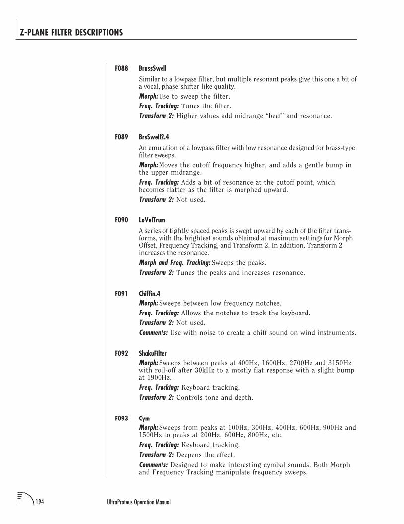
194 UltraProteus Operation Manual
Z-PLANE FILTER DESCRIPTIONS
F088 BrassSwellSimilar to a lowpass filter, but multiple resonant peaks give this one a bit ofa vocal, phase-shifter-like quality.
Morph: Use to sweep the filter.
Freq. Tracking: Tunes the filter.
Transform 2: Higher values add midrange “beef” and resonance.
F089 BrsSwell2.4An emulation of a lowpass filter with low resonance designed for brass-typefilter sweeps.
Morph: Moves the cutoff frequency higher, and adds a gentle bump inthe upper-midrange.
Freq. Tracking: Adds a bit of resonance at the cutoff point, whichbecomes flatter as the filter is morphed upward.
Transform 2: Not used.
F090 LoVelTrumA series of tightly spaced peaks is swept upward by each of the filter trans-forms, with the brightest sounds obtained at maximum settings for MorphOffset, Frequency Tracking, and Transform 2. In addition, Transform 2increases the resonance.
Morph and Freq. Tracking: Sweeps the peaks.
Transform 2: Tunes the peaks and increases resonance.
F091 Chiffin.4Morph: Sweeps between low frequency notches.
Freq. Tracking: Allows the notches to track the keyboard.
Transform 2: Not used.
Comments: Use with noise to create a chiff sound on wind instruments.
F092 ShakuFilterMorph: Sweeps between peaks at 400Hz, 1600Hz, 2700Hz and 3150Hzwith roll-off after 30kHz to a mostly flat response with a slight bumpat 1900Hz.
Freq. Tracking: Keyboard tracking.
Transform 2: Controls tone and depth.
F093 CymMorph: Sweeps from peaks at 100Hz, 300Hz, 400Hz, 600Hz, 900Hz and1500Hz to peaks at 200Hz, 600Hz, 800Hz, etc.
Freq. Tracking: Keyboard tracking.
Transform 2: Deepens the effect.
Comments: Designed to make interesting cymbal sounds. Both Morphand Frequency Tracking manipulate frequency sweeps.
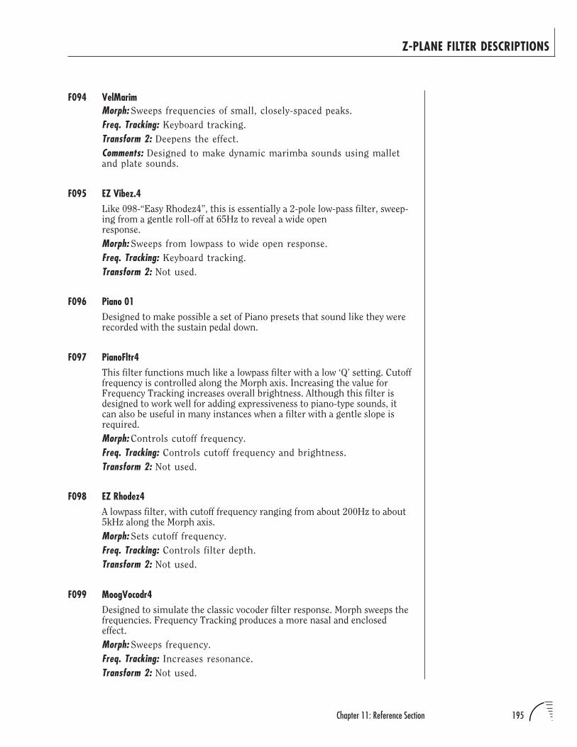
195Chapter 11: Reference Section
Z-PLANE FILTER DESCRIPTIONS
F094 VelMarimMorph: Sweeps frequencies of small, closely-spaced peaks.
Freq. Tracking: Keyboard tracking.
Transform 2: Deepens the effect.
Comments: Designed to make dynamic marimba sounds using malletand plate sounds.
F095 EZ Vibez.4Like 098-“Easy Rhodez4”, this is essentially a 2-pole low-pass filter, sweep-ing from a gentle roll-off at 65Hz to reveal a wide openresponse.
Morph: Sweeps from lowpass to wide open response.
Freq. Tracking: Keyboard tracking.
Transform 2: Not used.
F096 Piano 01Designed to make possible a set of Piano presets that sound like they wererecorded with the sustain pedal down.
F097 PianoFltr4This filter functions much like a lowpass filter with a low ‘Q’ setting. Cutofffrequency is controlled along the Morph axis. Increasing the value forFrequency Tracking increases overall brightness. Although this filter isdesigned to work well for adding expressiveness to piano-type sounds, itcan also be useful in many instances when a filter with a gentle slope isrequired.
Morph: Controls cutoff frequency.
Freq. Tracking: Controls cutoff frequency and brightness.
Transform 2: Not used.
F098 EZ Rhodez4A lowpass filter, with cutoff frequency ranging from about 200Hz to about5kHz along the Morph axis.
Morph: Sets cutoff frequency.
Freq. Tracking: Controls filter depth.
Transform 2: Not used.
F099 MoogVocodr4Designed to simulate the classic vocoder filter response. Morph sweeps thefrequencies. Frequency Tracking produces a more nasal and enclosedeffect.
Morph: Sweeps frequency.
Freq. Tracking: Increases resonance.
Transform 2: Not used.
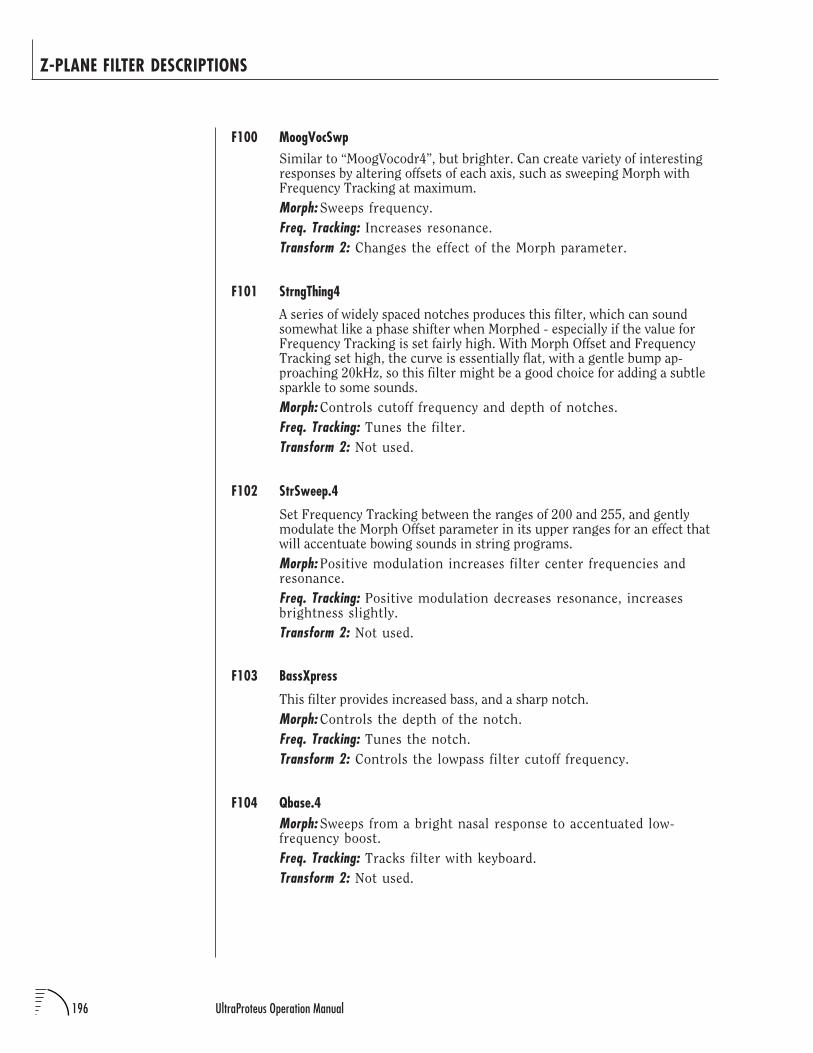
196 UltraProteus Operation Manual
Z-PLANE FILTER DESCRIPTIONS
F100 MoogVocSwpSimilar to “MoogVocodr4”, but brighter. Can create variety of interestingresponses by altering offsets of each axis, such as sweeping Morph withFrequency Tracking at maximum.
Morph: Sweeps frequency.
Freq. Tracking: Increases resonance.
Transform 2: Changes the effect of the Morph parameter.
F101 StrngThing4
A series of widely spaced notches produces this filter, which can soundsomewhat like a phase shifter when Morphed - especially if the value forFrequency Tracking is set fairly high. With Morph Offset and FrequencyTracking set high, the curve is essentially flat, with a gentle bump ap-proaching 20kHz, so this filter might be a good choice for adding a subtlesparkle to some sounds.
Morph: Controls cutoff frequency and depth of notches.
Freq. Tracking: Tunes the filter.
Transform 2: Not used.
F102 StrSweep.4
Set Frequency Tracking between the ranges of 200 and 255, and gentlymodulate the Morph Offset parameter in its upper ranges for an effect thatwill accentuate bowing sounds in string programs.
Morph: Positive modulation increases filter center frequencies andresonance.
Freq. Tracking: Positive modulation decreases resonance, increasesbrightness slightly.
Transform 2: Not used.
F103 BassXpress
This filter provides increased bass, and a sharp notch.
Morph: Controls the depth of the notch.
Freq. Tracking: Tunes the notch.
Transform 2: Controls the lowpass filter cutoff frequency.
F104 Qbase.4Morph: Sweeps from a bright nasal response to accentuated low-frequency boost.
Freq. Tracking: Tracks filter with keyboard.
Transform 2: Not used.
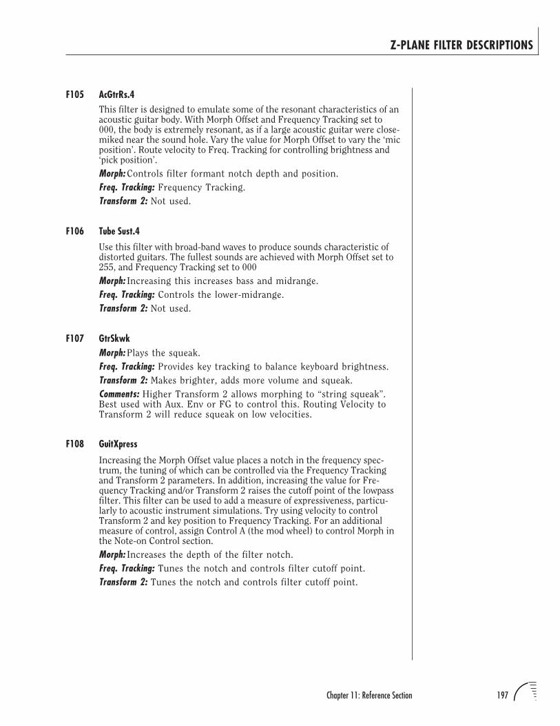
197Chapter 11: Reference Section
Z-PLANE FILTER DESCRIPTIONS
F105 AcGtrRs.4This filter is designed to emulate some of the resonant characteristics of anacoustic guitar body. With Morph Offset and Frequency Tracking set to000, the body is extremely resonant, as if a large acoustic guitar were close-miked near the sound hole. Vary the value for Morph Offset to vary the ‘micposition’. Route velocity to Freq. Tracking for controlling brightness and‘pick position’.
Morph: Controls filter formant notch depth and position.
Freq. Tracking: Frequency Tracking.
Transform 2: Not used.
F106 Tube Sust.4
Use this filter with broad-band waves to produce sounds characteristic ofdistorted guitars. The fullest sounds are achieved with Morph Offset set to255, and Frequency Tracking set to 000
Morph: Increasing this increases bass and midrange.
Freq. Tracking: Controls the lower-midrange.
Transform 2: Not used.
F107 GtrSkwkMorph: Plays the squeak.
Freq. Tracking: Provides key tracking to balance keyboard brightness.
Transform 2: Makes brighter, adds more volume and squeak.
Comments: Higher Transform 2 allows morphing to “string squeak”.Best used with Aux. Env or FG to control this. Routing Velocity toTransform 2 will reduce squeak on low velocities.
F108 GuitXpress
Increasing the Morph Offset value places a notch in the frequency spec-trum, the tuning of which can be controlled via the Frequency Trackingand Transform 2 parameters. In addition, increasing the value for Fre-quency Tracking and/or Transform 2 raises the cutoff point of the lowpassfilter. This filter can be used to add a measure of expressiveness, particu-larly to acoustic instrument simulations. Try using velocity to controlTransform 2 and key position to Frequency Tracking. For an additionalmeasure of control, assign Control A (the mod wheel) to control Morph inthe Note-on Control section.
Morph: Increases the depth of the filter notch.
Freq. Tracking: Tunes the notch and controls filter cutoff point.
Transform 2: Tunes the notch and controls filter cutoff point.
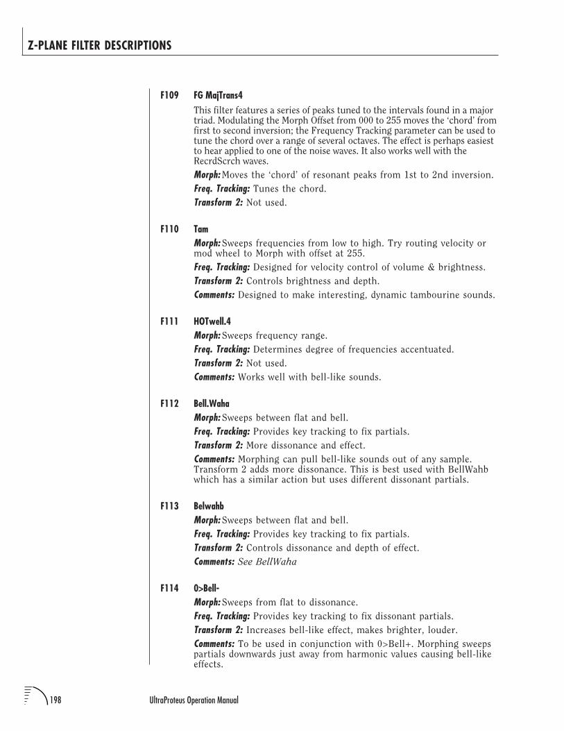
198 UltraProteus Operation Manual
Z-PLANE FILTER DESCRIPTIONS
F109 FG MajTrans4This filter features a series of peaks tuned to the intervals found in a majortriad. Modulating the Morph Offset from 000 to 255 moves the ‘chord’ fromfirst to second inversion; the Frequency Tracking parameter can be used totune the chord over a range of several octaves. The effect is perhaps easiestto hear applied to one of the noise waves. It also works well with theRecrdScrch waves.
Morph: Moves the ‘chord’ of resonant peaks from 1st to 2nd inversion.
Freq. Tracking: Tunes the chord.
Transform 2: Not used.
F110 TamMorph: Sweeps frequencies from low to high. Try routing velocity ormod wheel to Morph with offset at 255.
Freq. Tracking: Designed for velocity control of volume & brightness.
Transform 2: Controls brightness and depth.
Comments: Designed to make interesting, dynamic tambourine sounds.
F111 HOTwell.4Morph: Sweeps frequency range.
Freq. Tracking: Determines degree of frequencies accentuated.
Transform 2: Not used.
Comments: Works well with bell-like sounds.
F112 Bell.WahaMorph: Sweeps between flat and bell.
Freq. Tracking: Provides key tracking to fix partials.
Transform 2: More dissonance and effect.
Comments: Morphing can pull bell-like sounds out of any sample.Transform 2 adds more dissonance. This is best used with BellWahbwhich has a similar action but uses different dissonant partials.
F113 BelwahbMorph: Sweeps between flat and bell.
Freq. Tracking: Provides key tracking to fix partials.
Transform 2: Controls dissonance and depth of effect.
Comments: See BellWaha
F114 0>Bell-Morph: Sweeps from flat to dissonance.
Freq. Tracking: Provides key tracking to fix dissonant partials.
Transform 2: Increases bell-like effect, makes brighter, louder.
Comments: To be used in conjunction with 0>Bell+. Morphing sweepspartials downwards just away from harmonic values causing bell-likeeffects.
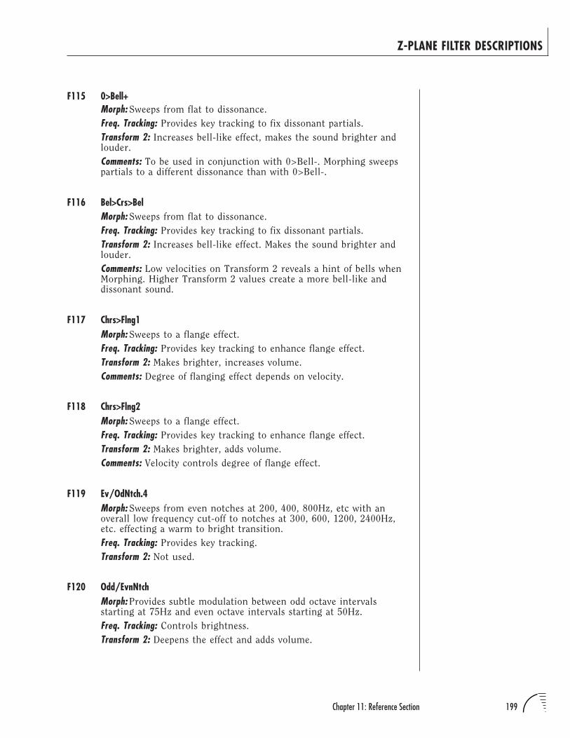
199Chapter 11: Reference Section
Z-PLANE FILTER DESCRIPTIONS
F115 0>Bell+Morph: Sweeps from flat to dissonance.
Freq. Tracking: Provides key tracking to fix dissonant partials.
Transform 2: Increases bell-like effect, makes the sound brighter andlouder.
Comments: To be used in conjunction with 0>Bell-. Morphing sweepspartials to a different dissonance than with 0>Bell-.
F116 Bel>Crs>BelMorph: Sweeps from flat to dissonance.
Freq. Tracking: Provides key tracking to fix dissonant partials.
Transform 2: Increases bell-like effect. Makes the sound brighter andlouder.
Comments: Low velocities on Transform 2 reveals a hint of bells whenMorphing. Higher Transform 2 values create a more bell-like anddissonant sound.
F117 Chrs>Flng1Morph: Sweeps to a flange effect.
Freq. Tracking: Provides key tracking to enhance flange effect.
Transform 2: Makes brighter, increases volume.
Comments: Degree of flanging effect depends on velocity.
F118 Chrs>Flng2Morph: Sweeps to a flange effect.
Freq. Tracking: Provides key tracking to enhance flange effect.
Transform 2: Makes brighter, adds volume.
Comments: Velocity controls degree of flange effect.
F119 Ev/OdNtch.4Morph: Sweeps from even notches at 200, 400, 800Hz, etc with anoverall low frequency cut-off to notches at 300, 600, 1200, 2400Hz,etc. effecting a warm to bright transition.
Freq. Tracking: Provides key tracking.
Transform 2: Not used.
F120 Odd/EvnNtchMorph: Provides subtle modulation between odd octave intervalsstarting at 75Hz and even octave intervals starting at 50Hz.
Freq. Tracking: Controls brightness.
Transform 2: Deepens the effect and adds volume.
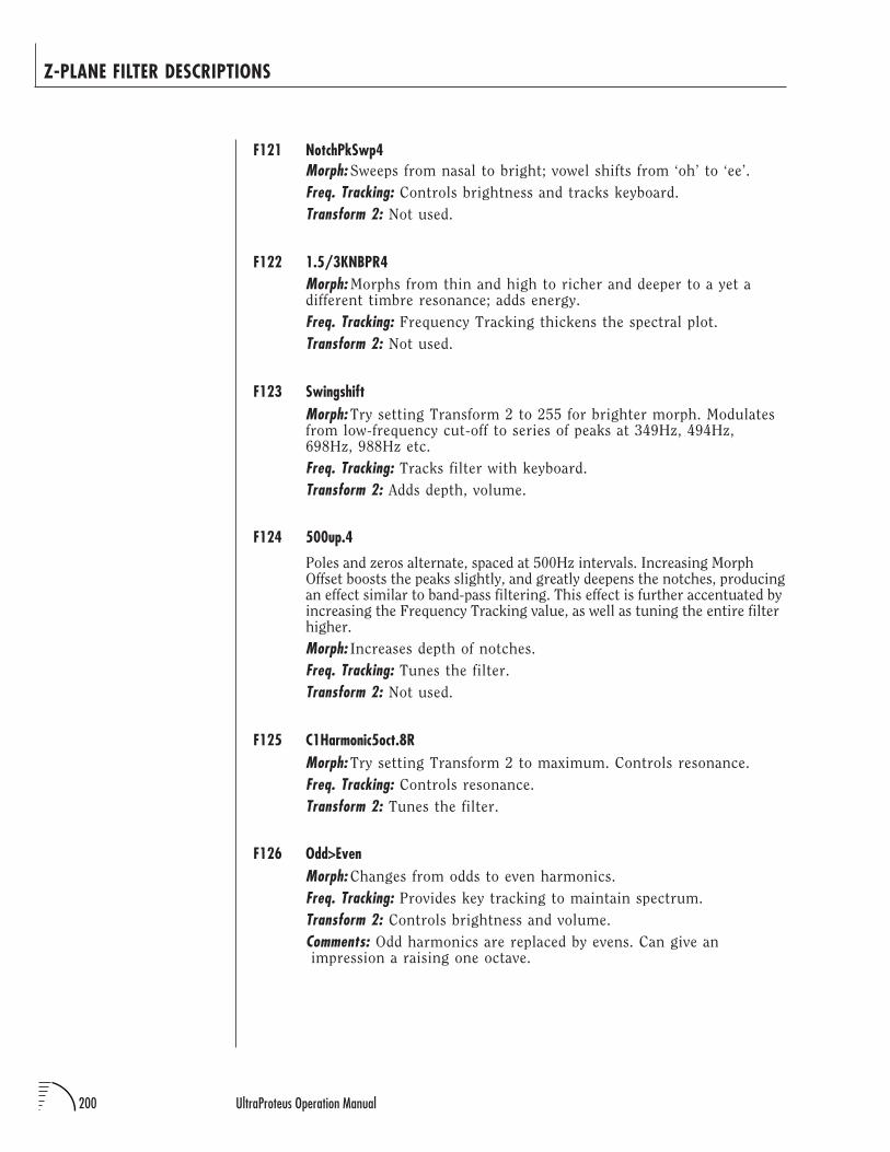
200 UltraProteus Operation Manual
Z-PLANE FILTER DESCRIPTIONS
F121 NotchPkSwp4Morph: Sweeps from nasal to bright; vowel shifts from ‘oh’ to ‘ee’.
Freq. Tracking: Controls brightness and tracks keyboard.
Transform 2: Not used.
F122 1.5/3KNBPR4Morph: Morphs from thin and high to richer and deeper to a yet adifferent timbre resonance; adds energy.
Freq. Tracking: Frequency Tracking thickens the spectral plot.
Transform 2: Not used.
F123 SwingshiftMorph: Try setting Transform 2 to 255 for brighter morph. Modulatesfrom low-frequency cut-off to series of peaks at 349Hz, 494Hz,698Hz, 988Hz etc.
Freq. Tracking: Tracks filter with keyboard.
Transform 2: Adds depth, volume.
F124 500up.4
Poles and zeros alternate, spaced at 500Hz intervals. Increasing MorphOffset boosts the peaks slightly, and greatly deepens the notches, producingan effect similar to band-pass filtering. This effect is further accentuated byincreasing the Frequency Tracking value, as well as tuning the entire filterhigher.
Morph: Increases depth of notches.
Freq. Tracking: Tunes the filter.
Transform 2: Not used.
F125 C1Harmonic5oct.8RMorph: Try setting Transform 2 to maximum. Controls resonance.
Freq. Tracking: Controls resonance.
Transform 2: Tunes the filter.
F126 Odd>EvenMorph: Changes from odds to even harmonics.
Freq. Tracking: Provides key tracking to maintain spectrum.
Transform 2: Controls brightness and volume.
Comments: Odd harmonics are replaced by evens. Can give an impression a raising one octave.
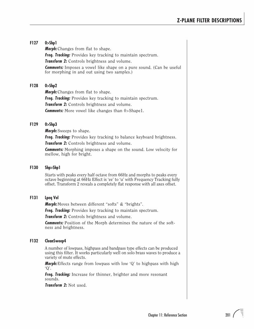
201Chapter 11: Reference Section
Z-PLANE FILTER DESCRIPTIONS
F127 0>Shp1Morph: Changes from flat to shape.
Freq. Tracking: Provides key tracking to maintain spectrum.
Transform 2: Controls brightness and volume.
Comments: Imposes a vowel like shape on a pure sound. (Can be usefulfor morphing in and out using two samples.)
F128 0>Shp2Morph: Changes from flat to shape.
Freq. Tracking: Provides key tracking to maintain spectrum.
Transform 2: Controls brightness and volume.
Comments: More vowel like changes than 0>Shape1.
F129 0>Shp3Morph: Sweeps to shape.
Freq. Tracking: Provides key tracking to balance keyboard brightness.
Transform 2: Controls brightness and volume.
Comments: Morphing imposes a shape on the sound. Low velocity formellow, high for bright.
F130 Shp>Shp1
Starts with peaks every half octave from 66Hz and morphs to peaks everyoctave beginning at 66Hz Effect is ‘ee’ to ‘u’ with Frequency Tracking fullyoffset. Transform 2 reveals a completely flat response with all axes offset.
F131 Lpeq VelMorph: Moves between different “softs” & “brights”.
Freq. Tracking: Provides key tracking to maintain spectrum.
Transform 2: Controls brightness and volume.
Comments: Position of the Morph determines the nature of the soft-ness and brightness.
F132 CleanSweep4
A number of lowpass, highpass and bandpass type effects can be producedusing this filter. It works particularly well on solo brass waves to produce avariety of mute effects.
Morph: Effects range from lowpass with low ‘Q’ to highpass with high‘Q’.
Freq. Tracking: Increase for thinner, brighter and more resonantsounds.
Transform 2: Not used.
202 UltraProteus Operation Manual
Z-PLANE FILTER DESCRIPTIONS
F133 PowerSweepsAlternating resonant peaks and notches, spaced at approximately half-octave intervals can be used to produce a number of flanging and vocaleffects. The direction of Morph depends on the Freq. Tracking setting.
Morph: Modulating this sweeps the peaks/notches up and/or down.
Freq. Tracking: Tunes the filter; determines polarity of Morph.
Transform 2: Can also be used to tune the filter.
F134 TSweep.4
A grouping of inharmonically related peaks gives this filter something of ametallic quality, although it can also produce voice-like sounds. IncreasingMorph Offset increases overall filter resonance and raises the cutoff point ofthe lowpass filter. Frequency Tracking can be used to tune the filter.
Morph: Controls ‘Q’; controls lowpass cutoff.
Freq. Tracking: Tunes the filter.
Transform 2: Not used.
F135 SweepHiQ1.4Morph: Sweeps from peaks at 150Hz, 430Hz, 870Hz , 1500Hz, 3000Hzand 7000Hz to peaks an octave higher.
Freq. Tracking: Introduces high Q peaks at 1.2kHz and 3.4kHz tonarrowly spaced peaks at 1500Hz to 15kHz.
Transform 2: Not used.
F136 V>FcQuad.4
Designed for velocity to control filter cut-off. Each frame has an octavehigher cut-off than the one before it.
Morph: Moves from a bump at 320Hz then a brickwall cut-off up anoctave.
Freq. Tracking: Tracks keyboard.
Transform 2: Not used.
F137 Nexus.4Morph: Moves from a brickwall low pass to higher frequency, relaxedslope response.
Freq. Tracking: Frequency Tracking at maximum inverts effect ofmorph.
Transform 2: Not used.
Comments: Designed for Frequency Tracking to control brightness withvelocity.
A “BRICKWALL” FILTER IS ONEWITH AN EXTREMELY STEEPSLOPE.
203Chapter 11: Reference Section
Z-PLANE FILTER DESCRIPTIONS
F138 Krators.4Morph: Provides resonant peaks at low-frequencies, morphing fromlower to higher frequency.
Freq. Tracking: Controls brightness.
Transform 2: Not used.
Comments: Designed to control brightness by assigning Velocity toFrequency Tracking.
F139 Harmonix.4Morph: Morphs between complex responses sweeping mid frequencyresonances while leaving edges untouched.
Freq. Tracking: Controls brightness and tracks keyboard.
Transform 2: Not used.
F140 GreenWorld4Morph: A mellow low-frequency sweeper designed for piano applica-tions.
Freq. Tracking: Controls brightness and tracks keyboard.
Transform 2: Not used.
F141 Comb/Swap.4Morph: Controls a series of notches moving from 160Hz to 10kHz.
Freq. Tracking: Controls brightness and tracks keyboard.
Transform 2: Not used.
F142 Comb/HP.4Morph: Sweeps between a series of low frequency notches to a highpass response.
Freq. Tracking: Keyboard Tracking and brightness control.
Transform 2: Not used.
Comments: Control the brightness by assigning Velocity to FrequencyTracking.
F143 SwirlyMorph: Moves from series of notches to fewer notches.
Freq. Tracking: Tracks keyboard.
Transform 2: Alters timbre of effect and adds dynamics.
Comments: Try a Transform 2 setting of 255 for a brighter Morph.
F144 Cavatate.4
Emphasizes frequencies from 160Hz to 2kHz.
Morph: Morphs to a modified high pass response.
Freq. Tracking: Brightness control.
Transform 2: Not used.
204 UltraProteus Operation Manual
Z-PLANE FILTER DESCRIPTIONS
F145 GentleRZ4A series of unevenly spaced resonant peaks converge to a single peak asMorph Offset is increased. The Frequency Tracking offset provides asomewhat muted sound (with several gentle bumps in the mid-frequencyrange), moving toward a flat response. Sweeping this filter produces somevery smooth wa-wa effects. Using this filter with the trumpet waves canproduce sounds suggestive of French Horns.
Morph: Modulating this sweeps filter peaks.
Freq. Tracking: Use this to control filter depth and cutoff.
Transform 2: Not used.
F146 Bendup/Swap
This complex filter features several series of tuned resonant peaks andnotches which can seem to bend up or down in pitch depending on thesettings for the various Morph, Frequency Tracking, andTransform 2 parameters.
Morph: Use to tune the filter.
Freq. Tracking: Low values make upward filter sweeps appear to bendpitch up. High values make pitch bend appear to go down.
Transform 2: Higher values make the filter sound more open.
F147 Bendup
This is similar to filter number 160, except that the bend is always in anupward direction (if the Morph axis is swept in a positive direction).Frequency Tracking can be used to tune the filter over a nearly 2-octaverange. Transform 2 is used to set the cutoff point of the lowpass filter;higher values raise the cutoff point.
Morph: Sweeps harmonic peaks.
Freq. Tracking: Tunes the filter.
Transform 2: Increase for a brighter effect.
F148 SKWEEZIT
This filter features a complex series of peaks and notches. Varying theMorph parameter varies the ‘Q’ settings for most of the peaks and notches,while sweeping the frequency and Q of the first pole.
Morph: Sweeps one of the resonant peaks and varies ‘Q’.
Freq. Tracking: Tunes the filter.
Transform 2: Controls resonance.
205Chapter 11: Reference Section
Z-PLANE FILTER DESCRIPTIONS
F149 Lo/High4A scattering of poles and zeros with fairly high Q settings produces thisvery resonant filter. Sweeping the Morph axis produces quite pronouncedwa-wa effects in which multiple resonances are clearly audible. MorphOffset and Frequency Tracking can be used to tune the filter, although withMorph Offset set to 255, the filter is essentially flat.
Morph: Positive values increase pole/zero frequencies and decrease ‘Q’,opening the filter entirely.
Freq. Tracking: Similar to the Morph axis, but a bit higher in pitch.
Transform 2: Not used.
F150 SbtleMvmnt4
Morphing this filter to reverse the polarity of a series of more-or-less evenlyspaced peaks and notches produces an effect more subdued than sometypes of filter sweeps. Using velocity or a mod wheel (assigned through theNote-on Control section) to control the Morph parameter can be usefulwhen developing responsive plucked-string instrument sounds, such asguitar.
Morph: Controls polarity of poles.
Freq. Tracking: Tunes the filter.
Transform 2: Not used.
F151 Buzzy Pad.4
This filter produces a bump at 65Hz and a rolloff above 250Hz at lowMorph values. Increasing the Morph value pushes the bump up to about2kHz, and the cutoff of the lowpass filter up to 20kHz. Increasing the valueof Frequency Tracking sends the bump higher yet — up to about 8400Hz atmaximum offset. The effect of sweeping the Morph axis is similar to that ofa classic 2-pole lowpass filter with medium resonance.
Morph: Tunes the filter.
Freq. Tracking: Tunes the filter.
Transform 2: Not used.
F152 Bw5kHz+6.4
Lowpass cutoff is set to 400Hz with ‘0’ Morph Offset. In addition, there is a6 dB bump at 5kHz. The bandwidth of this “bump” is controlled by theMorph parameter. Sweeping the Morph Offset upwards moves the band-width setting from very narrow to very wide. Frequency Tracking movesthe cutoff frequency of the lowpass filter up to a maximum of 20kHz. Therange of effects available is from fairly dramatic to quite subtle.
Morph: Controls filter bandwidth.
Freq. Tracking: Controls filter cutoff.
Transform 2: Not used.
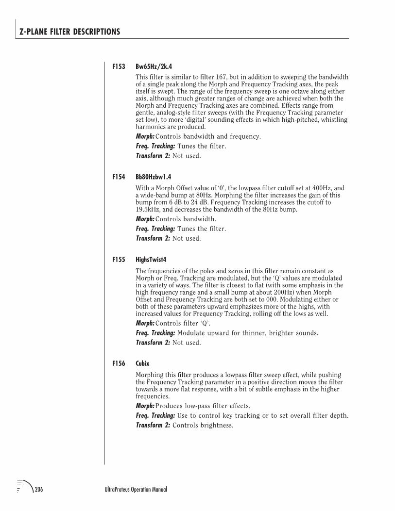
206 UltraProteus Operation Manual
Z-PLANE FILTER DESCRIPTIONS
F153 Bw65Hz/2k.4This filter is similar to filter 167, but in addition to sweeping the bandwidthof a single peak along the Morph and Frequency Tracking axes, the peakitself is swept. The range of the frequency sweep is one octave along eitheraxis, although much greater ranges of change are achieved when both theMorph and Frequency Tracking axes are combined. Effects range fromgentle, analog-style filter sweeps (with the Frequency Tracking parameterset low), to more ‘digital’ sounding effects in which high-pitched, whistlingharmonics are produced.
Morph: Controls bandwidth and frequency.
Freq. Tracking: Tunes the filter.
Transform 2: Not used.
F154 Bb80Hzbw1.4
With a Morph Offset value of ‘0’, the lowpass filter cutoff set at 400Hz, anda wide-band bump at 80Hz. Morphing the filter increases the gain of thisbump from 6 dB to 24 dB. Frequency Tracking increases the cutoff to19.5kHz, and decreases the bandwidth of the 80Hz bump.
Morph: Controls bandwidth.
Freq. Tracking: Tunes the filter.
Transform 2: Not used.
F155 HighsTwist4
The frequencies of the poles and zeros in this filter remain constant asMorph or Freq. Tracking are modulated, but the ‘Q’ values are modulatedin a variety of ways. The filter is closest to flat (with some emphasis in thehigh frequency range and a small bump at about 200Hz) when MorphOffset and Frequency Tracking are both set to 000. Modulating either orboth of these parameters upward emphasizes more of the highs, withincreased values for Frequency Tracking, rolling off the lows as well.
Morph: Controls filter ‘Q’.
Freq. Tracking: Modulate upward for thinner, brighter sounds.
Transform 2: Not used.
F156 Cubix
Morphing this filter produces a lowpass filter sweep effect, while pushingthe Frequency Tracking parameter in a positive direction moves the filtertowards a more flat response, with a bit of subtle emphasis in the higherfrequencies.
Morph: Produces low-pass filter effects.
Freq. Tracking: Use to control key tracking or to set overall filter depth.
Transform 2: Controls brightness.
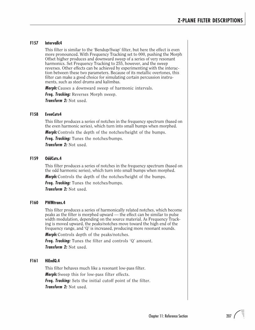
207Chapter 11: Reference Section
Z-PLANE FILTER DESCRIPTIONS
F157 Intervallc4This filter is similar to the ‘Bendup/Swap’ filter, but here the effect is evenmore pronounced. With Frequency Tracking set to 000, pushing the MorphOffset higher produces and downward sweep of a series of very resonantharmonics. Set Frequency Tracking to 255, however, and the sweepreverses. Other effects can be achieved by experimenting with the interac-tion between these two parameters. Because of its metallic overtones, thisfilter can make a good choice for simulating certain percussion instru-ments, such as steel drums and kalimbas.
Morph: Causes a downward sweep of harmonic intervals.
Freq. Tracking: Reverses Morph sweep.
Transform 2: Not used.
F158 EvenCuts4
This filter produces a series of notches in the frequency spectrum (based onthe even harmonic series), which turn into small bumps when morphed.
Morph: Controls the depth of the notches/height of the bumps.
Freq. Tracking: Tunes the notches/bumps.
Transform 2: Not used.
F159 OddCuts.4
This filter produces a series of notches in the frequency spectrum (based onthe odd harmonic series), which turn into small bumps when morphed.
Morph: Controls the depth of the notches/height of the bumps.
Freq. Tracking: Tunes the notches/bumps.
Transform 2: Not used.
F160 PWMtrans.4
This filter produces a series of harmonically related notches, which becomepeaks as the filter is morphed upward — the effect can be similar to pulsewidth modulation, depending on the source material. As Frequency Track-ing is moved upward, the peaks/notches move toward the high end of thefrequency range, and ‘Q’ is increased, producing more resonant sounds.
Morph: Controls depth of the peaks/notches.
Freq. Tracking: Tunes the filter and controls ‘Q’ amount.
Transform 2: Not used.
F161 HiEndQ.4
This filter behaves much like a resonant low-pass filter.
Morph: Sweep this for low-pass filter effects.
Freq. Tracking: Sets the initial cutoff point of the filter.
Transform 2: Not used.
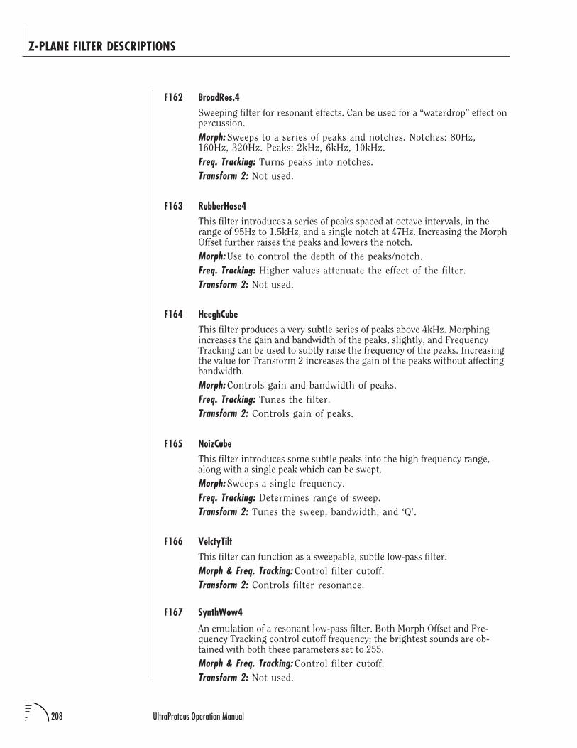
208 UltraProteus Operation Manual
Z-PLANE FILTER DESCRIPTIONS
F162 BroadRes.4Sweeping filter for resonant effects. Can be used for a “waterdrop” effect onpercussion.
Morph: Sweeps to a series of peaks and notches. Notches: 80Hz,160Hz, 320Hz. Peaks: 2kHz, 6kHz, 10kHz.
Freq. Tracking: Turns peaks into notches.
Transform 2: Not used.
F163 RubberHose4This filter introduces a series of peaks spaced at octave intervals, in therange of 95Hz to 1.5kHz, and a single notch at 47Hz. Increasing the MorphOffset further raises the peaks and lowers the notch.
Morph: Use to control the depth of the peaks/notch.
Freq. Tracking: Higher values attenuate the effect of the filter.
Transform 2: Not used.
F164 HeeghCubeThis filter produces a very subtle series of peaks above 4kHz. Morphingincreases the gain and bandwidth of the peaks, slightly, and FrequencyTracking can be used to subtly raise the frequency of the peaks. Increasingthe value for Transform 2 increases the gain of the peaks without affectingbandwidth.
Morph: Controls gain and bandwidth of peaks.
Freq. Tracking: Tunes the filter.
Transform 2: Controls gain of peaks.
F165 NoizCubeThis filter introduces some subtle peaks into the high frequency range,along with a single peak which can be swept.
Morph: Sweeps a single frequency.
Freq. Tracking: Determines range of sweep.
Transform 2: Tunes the sweep, bandwidth, and ‘Q’.
F166 VelctyTiltThis filter can function as a sweepable, subtle low-pass filter.
Morph & Freq. Tracking: Control filter cutoff.
Transform 2: Controls filter resonance.
F167 SynthWow4
An emulation of a resonant low-pass filter. Both Morph Offset and Fre-quency Tracking control cutoff frequency; the brightest sounds are ob-tained with both these parameters set to 255.
Morph & Freq. Tracking: Control filter cutoff.
Transform 2: Not used.
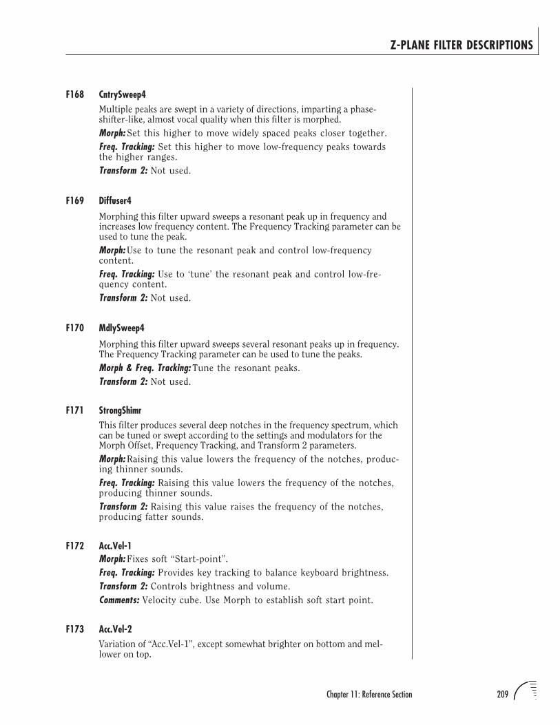
209Chapter 11: Reference Section
F168 CntrySweep4Multiple peaks are swept in a variety of directions, imparting a phase-shifter-like, almost vocal quality when this filter is morphed.
Morph: Set this higher to move widely spaced peaks closer together.
Freq. Tracking: Set this higher to move low-frequency peaks towardsthe higher ranges.
Transform 2: Not used.
F169 Diffuser4
Morphing this filter upward sweeps a resonant peak up in frequency andincreases low frequency content. The Frequency Tracking parameter can beused to tune the peak.
Morph: Use to tune the resonant peak and control low-frequencycontent.
Freq. Tracking: Use to ‘tune’ the resonant peak and control low-fre-quency content.
Transform 2: Not used.
F170 MdlySweep4
Morphing this filter upward sweeps several resonant peaks up in frequency.The Frequency Tracking parameter can be used to tune the peaks.
Morph & Freq. Tracking: Tune the resonant peaks.
Transform 2: Not used.
F171 StrongShimrThis filter produces several deep notches in the frequency spectrum, whichcan be tuned or swept according to the settings and modulators for theMorph Offset, Frequency Tracking, and Transform 2 parameters.
Morph: Raising this value lowers the frequency of the notches, produc-ing thinner sounds.
Freq. Tracking: Raising this value lowers the frequency of the notches,producing thinner sounds.
Transform 2: Raising this value raises the frequency of the notches,producing fatter sounds.
F172 Acc.Vel-1Morph: Fixes soft “Start-point”.
Freq. Tracking: Provides key tracking to balance keyboard brightness.
Transform 2: Controls brightness and volume.
Comments: Velocity cube. Use Morph to establish soft start point.
F173 Acc.Vel-2Variation of “Acc.Vel-1”, except somewhat brighter on bottom and mel-lower on top.
Z-PLANE FILTER DESCRIPTIONS
210 UltraProteus Operation Manual
F174 Vel2-WindMorph: Fixes soft “Start-point”.
Freq. Tracking: Provides key tracking to balance keyboard brightness.
Transform 2: Controls brightness and volume.
Comments: Velocity cube. Use morph to establish soft start point. Goodfor wind instruments as more morph gives a “hollower” soft sound.
F175 HarmoMorph: Changes from “peaky” lowpass response to smooth lowpass.
Freq. Tracking: Provides key tracking to balance keyboard brightness.
Transform 2: Controls volume, brightness and dissonance.
Comments: Cube construction - Use the Aux. Envelope to provideattack transient which then fades off to rear frames.
F176 Start>EndAMorph: Complex peak at 80Hz to a very gentle lowpass response.
Freq. Tracking: Provides key tracking to balance keyboard brightness.
Transform 2: Brighter, more volume, more harmonics.
Comments: Cube construction - Use the Aux. Envelope to provide attacktransient which then fades off to rear frames. Softer version than“HarmoEP”. Volume changes for sensitivity are maintained in thecube.
F177 Start>EndBMorph: Flat response to gentle lowpass.
Freq. Tracking: Key tracking to balance keyboard brightness.
Transform 2: Controls volume, brightness and harmonic content.
Comments: Same model as Start>EndA but more bright and dissonant.
F178 MovingPick1Morph: Tight<>Hollow
Freq. Tracking: Provides key tracking to balance keyboard brightness.
Transform 2: Controls brightness and volume.
Comments: Uses Morph to simulate acoustic versus electric typeresponse to velocity: plucking closer or further from the bridge of aguitar for example.
F179 MovingPick2
A variation on “MovingPick1” to simulate different pick positions, forexample. Morph moves closer to neck, further from bridge.
Z-PLANE FILTER DESCRIPTIONS
211Chapter 11: Reference Section
F180 Mph+Trns1Morph: Makes vowel like changes.
Freq. Tracking: Provides key tracking to enhance vowel.
Transform 2: Controls vowels, brightness, volume.
Comments: Uses Morph to sweep from one vowel to another. Transform2 takes care of velocity expression.
F181 0>OddsMorph: Sweeps from flat to odds only.
Freq. Tracking: Provides key tracking to fix partials.
Transform 2: Controls brightness and volume.
Comments: Strong odds only spectrum with morphing. Transform 2takes care of brightness.
F182 Comb Voices
Center frequencies of the poles and zeros in this filter can move in oppositedirections as the filter is modulated along any of its axes, producing anamazing variety of possible curves. Sweeping the Morph axis producessome lovely phase-shifter/flanger-type effects, especially with the value forTransform 2 set fairly high.
Morph: Use this to animate the comb-filtering effect.
Freq. Tracking: Generally, this can be used to tune the filter.
Transform 2: Moves the filter toward more open sounds.
F183 Odd-Ev Hrm
A series of peaks and notches based on the odd and even harmonic series.Sweeping the Morph axis produces some lovely comb filtering effects,which can be either subtle or dramatic depending on other settings(especially that of Transform 2).
Morph: Use this to sweep the peaks/notches.
Freq. Tracking: Tunes the filter.
Transform 2: Tunes the filter and controls resonance.
F184 OddHrm+rez
This filter cube, based on the odd harmonic series, provides a number ofcomb-filtering effects. Use the Morph Offset to control filter ‘Q’, andFrequency Tracking and Transform 2 to tune the filter.
Morph: Increasing this parameter pushes the filter towards a flatcurve.
Freq. Tracking: Tunes the filter.
Transform 2: Tunes the filter. Higher values add a high-frequencybump.
Z-PLANE FILTER DESCRIPTIONS
212 UltraProteus Operation Manual
F185 EvnHrm+rezThis filter cube is nearly identical to the ‘OddHrm+rez’ filter, but it’s basedon the even harmonic series. The overall effect is quite similar, thoughsomewhat less ‘hollow’ sound at certain settings.
Morph: Increasing this parameter pushes the filter towards a flat curveand reduced ‘Q’.
Freq. Tracking: Tunes the filter.
Transform 2: Tunes the filter. Higher values add a high-frequencybump.
F186 MellowPeaksThis filter provides two or three mildly resonant poles which can be sweptthrough the frequency spectrum in a number of ways, depending on thesettings for the various parameters. With lower settings for FrequencyTracking , the filter takes on a distinctly vocal quality on most sourcematerial.
Morph: Positive values generally move the poles upward in frequency.
Freq. Tracking: Positive values generally move the poles upward infrequency.
Transform 2: Positive values generally move the poles upward infrequency.
F187 AHmBnd.4The Morph Offset can be swept to sweep a cluster of resonant peaks,producing a pitch-bend effect. The effect is generally most pronouncedwith Frequency Tracking set to a fairly low value.
Morph: Sweeping produces ‘pitch-bend’ effect.
Freq. Tracking: Tunes the filter.
Transform 2: Not used.
F188 VintageFeatures an accentuated low end, and a series of notches which can beswept via morphing. The most dramatic resonant sweeps are produced withFrequency Tracking set to minimum and Transform 2 set to maximum,producing the classic analog filter sweep sound.
Morph: Use to sweep the filter.
Freq. Tracking: Tunes the filter.
Transform 2: Controls filter resonance.
F189 MildQPoleMorph: Sweeps between a shallow roll-off low-pass to almost flatresponse.
Freq. Tracking: Tracks keyboard.
Transform 2: At maximum, inverts morph effect.
Z-PLANE FILTER DESCRIPTIONS
213Chapter 11: Reference Section
F190 Bonk>COA series of highly resonant peaks alternating with notches are spaced atintervals of about an octave. The Morph Offset parameter is used to control‘Q’ — modulating the Morph Offset upward causes the curve to flatten out.Frequency Tracking can be used to tune the peaks/notches; higher valuesmove the peaks/notches into higher frequency ranges. Transform 2 alsotunes the filter, but higher values cause the notches to move down infrequency, slightly. The overall effect of the filter can be very vocal, depend-ing on the source material.
Morph: Controls resonance.
Freq. Tracking: Tunes the filter.
Transform 2: Subtly tunes the filter.
F191 Speaker
Groups of unevenly spaced bumps and dips in the frequency spectrum areused to simulate a number of speaker cabinet responses. Use Morph Offset,Frequency Tracking, and Transform 2 to vary the tuning and depth of thebumps and dips to simulate different speaker cabinet types.
All Axes: Vary center frequency and amount of boost/cut for thevarious filter bands.
F192 Expander
Frequency Tracking and Transform 2 provide a range of fairly broad-bandboosts and cuts at various frequencies, with higher values generally provid-ing thinner, brighter sounds. These can be used to add a measure ofexpressiveness to the source material — route ‘Key’ to control FrequencyTracking, for example, and ‘Vel’ to control Transform 2. Increasing thevalue for Morph Offset has the effect of flattening the curve, providing youwith a filter depth control.
Morph: Use to control filter depth.
Freq. Tracking: Higher values produce thinner, brighter sounds.
Transform 2: Higher values produce thinner, brighter sounds.
F193 Separator
This filter features three inharmonically related resonant peaks, which canbe swept via the Morph parameter, producing a metallic set of overtones.Applied to the noise waves, this can sound like whistling wind; applied topitch sounds, it can produce anything from a hollow, metallic resonancesto accentuated high-frequency attack transients.
Morph: Use to sweep the resonant peaks.
Freq. Tracking: Tunes the filter.
Transform 2: Controls filter resonance.
Z-PLANE FILTER DESCRIPTIONS
214 UltraProteus Operation Manual
Z-PLANE FILTER DESCRIPTIONS
F194 MildPolSwapBasically, a variable cut-off low pass filter.
Morph: Tunes the filter.
Freq. Tracking: Tunes the filter.
Transform 2: Adds extra brightness to high morph.
DISTORTIONSJump Back! The Filter Level is useful to control the distortion filters.
F195 PoleCross.4Crossing poles produces certain “hot” or “sweet” spots wherefrequencies correlate.
Morph: Crosses filter “poles” to create hot (distortion) or sweet spots.
Freq. Tracking: Adds extra bite to Morph.
Transform 2: Not used.
F196 ApDistB6.4Reducing the Filter Level parameter in the preset will not only reduce thevolume level, it will also reduce the amount of distortion effect. Therefore,routing velocity, mod wheel, pressure, pedal, etc to Filter Level controlsthe distortion’s depth as well as volume.
F197 TubeJam.4All rules are broken here. Peaks are intentionally clipped, yet outputvolume is within tolerance....barely! Only the morph axis is active.
Freq. Tracking: Not used.
Transform 2: Not used.
215Chapter 11: Reference Section
VARI-POLE FILTERSThis group of lowpass filters all have a variable slope. Variable slope filters are
very rare in synthesizers, but the effect of the variable slope occurs in natural
sounds. The number of poles relates to the maximum steepness of the filter.
F198 Poles 1-7Morph: Controls filter cut-off (Fc); range is from approx 20Hz-20kHz.
Freq. Tracking: Low values produce 1 pole filter; high values produce 7
pole version.
Transform 2: Higher values increase Q. For best keyboard tracking,
route key tracking to Morph +088, and set Keyboard Center to C1.
F199 2 PolesMorph: Controls Fc; range is from approx 20Hz-20kHz.
Freq. Tracking: Higher values increase Q for a single pole.
Transform 2: Higher values increase Q for both poles. For best key-board tracking, route key tracking to Morph +088, and set KeyboardCenter to C1. Note that Freq. Track has no effect with Transform 2set to 255 and that distortion can be produced.
F200 4 Poles AA useful filter for bass sounds. Set Morph and Freq. Track to 255 andTransform 2 to 000 for flat response.
Morph: Controls Fc; range is from approx 20Hz - 320Hz.
Freq. Tracking:: Controls Fc; range is from approx 320Hz-20kHz.
Transform 2: Higher values increase Q.
F201 4 Poles BMorph: Controls Fc; range is from approx 20Hz-20kHz.
Freq. Tracking: Higher values flatten response.
Transform 2: Higher values increase Q. For best keyboard tracking,route key tracking to Morph +088, and set Keyboard Center to C1.
F202 4 Poles CMorph: Controls Fc; range is from approx 20Hz-20kHz.
Freq. Tracking: Higher values decrease filter range.
Transform 2: Higher values increase Q.
F203 6 PolesMorph: Controls Fc; range is from approx 20Hz-20kHz.
Freq. Tracking: Higher values produce flatter curve.
Transform 2: Higher values increase Q. For best keyboard tracking,route key tracking to Morph +088, and set Keyboard Center to C1.
Z-PLANE FILTER DESCRIPTIONS
216 UltraProteus Operation Manual
Z-PLANE FILTER DESCRIPTIONS
F204 MultipoleMorph: Controls Fc in lower ranges.
Freq. Tracking: Controls Fc in higher ranges.
Transform 2: Higher values increase Q and re-order some poles. Peakstuned to octaves are swept along the Morph axis.
TRACKING FILTERSThese filters range from lowpass to resonant peaking filters. The Frequency
Tracking parameter allows the filter to “track” specific harmonics as you play up
and down the keyboard.
F205 Tracker
Simple lowpass filter. For best keyboard tracking, route key tracking toMorph +088, and set Keyboard Center to C1. Set both Filt. Freq. Track andTransform 2 to 255 for ‘Ultra Q’ lowpass.
Morph: Controls Fc; range is from approx 20Hz-20kHz.
Freq. Tracking: Higher values increase Q.
Transform 2: Higher values increase multi-band Q.
F206 Tracker 2Morph: Tunes the peak.
Freq. Tracking: Tunes the peak.
Transform 2: Higher values increase the gain of the peak. A singleresonant peak can be added and moved around via Morphing andFreq. Tracking. Best tracking is achieved with Key to Freq. Track+117.
F207 Tracker 3Morph: Tunes the “chord”.
Freq. Tracking: Controls LP Fc.
Transform 2: Higher values produce flatter filter. Filter bands tuned toa suspended chord can be pushed along the Morph axis. For mostaccurate key tracking, set Key to Morph +127.
F208 Tracker5thsMorph: Increases filter peak gains.
Freq. Tracking: Tunes the filter.
Transform 2: Use as LP filter (lower values = darker). Harmonic peakstuned to fifths. For most accurate key tracking, set Key to Freq.Track +127.
Fc STANDS FOR THE CENTERFREQUENCY OF A FILTER.
217Chapter 11: Reference Section
Z-PLANE FILTER DESCRIPTIONS
F209 InFifths.4The filter thins and mellows out almost any sound. Morphing has the effectof adding low end warmth. Nice with cellos, hip with trombones. All filtersare scaled for Keyboard Center C1.
Morph: Starts with the fundamental, and the 5th and their multiplesfrom 65Hz through 16.64kHz attenuated by 18dB. Results in thefundamental, 5th and their multiples from 65Hz through 16.64kHzboosted by 18dB.
Freq. Tracking: Tunes the filter.
Transform 2: Not Used.
F210 HarmTrackerLots of harmonically related peaks in this one. Best tracking is obtainedwith Key Center C1, and Key to Filt. Freq. Track +127.
Morph: Increases gain of peaks.
Freq. Tracking: Tunes the filter.
Transform 2: Shifts balance from lower filter bands to upper.
PARAMETRIC TRACKING FILTERSThese filters are set up with various interesting combinations of peaks and
notches. The Frequency Tracking parameter controls various functions such as
bandwidth, amount and Fc.
F211 1BndPrmtrcAMorph: Controls Fc; range is from approx 20Hz-20kHz.
Freq. Tracking: Higher values increase bandwidth.
Transform 2: Values below 127 produce notches; above produce peaks.Set Transform 2 to 127 for closest to flat response.
F212 1BndPrmtrcBFor best keyboard tracking, route Key to Morph +092, and set KeyboardCenter to C1. Set Transform 2 to 127 for closest to flat response.
Morph: Controls Fc; range is from approx 80Hz-18kHz.
Freq. Tracking: Values below 127 produce notches; above producepeaks.
Transform 2: Higher values increase bandwidth.
F213 1BndPrmtrcCIdentical to F212 1BndPrmtrcB, except that Morph can be used to controlamount of boost or cut, rather than Fc.
Morph: Values below 127 produce notches; above produce peaks.
Freq. Tracking: Controls Fc; range is from approx 80Hz-18kHz.
Transform 2: Higher values increase bandwidth.
218 UltraProteus Operation Manual
Z-PLANE FILTER DESCRIPTIONS
F214 1BndPrmtrcD
Very similar to F212 1BndPrmtrcB, but with bigger boosts and cuts.
Morph: Controls Fc; range is from approx 80Hz-18kHz.
Freq. Tracking: Values below 127 produce notches; above producepeaks.
Transform 2: Higher values increase bandwidth.
F215 MultiMetricA
A series of adjustable peaks and notches tuned to octaves. For best key-board tracking, route Key to Morph +127, and set Keyboard Center to C1.
Morph: Controls Fc; range is from approx 40Hz-20kHz.
Freq. Tracking: Values below 127 produce notches, above producepeaks.
Transform 2: Higher values increase bandwidth.
F216 MultiMetricB
A series of adjustable peaks and notches tuned to even harmonics. For bestkeyboard tracking, route Key to Morph +127, and set Keyboard Center toC1.
Morph: Controls Fc; range is from approx 80Hz-18kHz.
Freq. Tracking: Values below 127 produce notches, above producepeaks.
Transform 2: Higher values increase bandwidth.
F217 MultiMetricC
A series of adjustable peaks and notches tuned to odd harmonics. For bestkeyboard tracking, route Key to Morph +127, and set Keyboard Center toC1. Set Transform 2 to 127 for closest to flat response.
Morph: Controls Fc; range is from approx 80Hz-18kHz.
Freq. Tracking: Values below 127 produce notches, above producepeaks.
Transform 2: Higher values increase bandwidth.
F218 Omni Metric
Use Filt. Freq. Track to control whether filter produces peaks or notches(higher values produce peaks), and use Morph to tune them (higher valuesmove them lower in frequency). Increasing Transform 2 flattens response.
Morph: Tunes the filter.
Freq. Tracking: Controls polarity.
Transform 2: Controls overall filter depth.
219Chapter 11: Reference Section
Z-PLANE FILTER DESCRIPTIONS
HARMONIC SHIFTERSThese filters are are designed to alter the normal harmonic relationships of
instruments by radically shifting the resonant frequency bands using the Morph
parameter. The Frequency Tracking parameter allows the filter to “track”
specific harmonics as you play up and down the keyboard.
F219 HrmncPeaks
Filter bands can be tuned using Freq. Track; Morph simply controls whichbands produce peaks. Note that if Transform 2 and Freq. Track are both setto 000, probably no sound will be heard.
Morph: At 000, even numbered filter bands produce peaks. At 255,peaks are all odd frequencies.
Freq. Tracking: Tunes the filters.
Transform 2: Lowpass effect; higher values open the filter.
F220 HrmncPeaks2
Filter bands can be tuned using Freq. Track; Morph simply controls whichbands produce peaks.
Morph: At 000, peaks are even harmonics. At 255, peaks are oddharmonics.
Freq. Tracking: Tunes the filters.
Transform 2: Higher values raise Fc of lowpass filter.
F221 InHarMetric
The peaks and notches in this filter are spaced evenly, though not necessar-ily harmonically, through approximately a four-octave range.
Morph: Controls bandwidth.
Freq. Tracking: Tunes the filter.
Transform 2: Controls polarity; low values produce peaks, high valuesproduce notches.
F222 HarmShifterMorph: Shifts emphasis from lower filters to higher.
Freq. Tracking: Tunes the filter.
Transform 2: Higher values increase filter bandwidth.
F223 HarmShiftr2Morph: Shifts emphasis from lower filters to higher.
Freq. Tracking: Tunes the filter.
Transform 2: 000=peaks, 255=notches, 127=flat.
220 UltraProteus Operation Manual
Z-PLANE FILTER DESCRIPTIONS
F224 HarmShiftr3
Harmonically related filter bands can be moved around by adjusting Filt.Freq. Track. Higher values for Transform 2 increase overall filter effect.
Morph: Higher values decrease bandwidth.
Freq. Tracking: Tunes the filters.
Transform 2: Increases depth of peaks and notches.
F225 PhaserMorph: Spreads all the filters from a single frequency to multiplefrequencies.
Freq. Tracking: Controls polarity of the filters; below 127 yieldsnotches, above, peaks.
Transform 2: Controls filter bandwidth; higher values are wider bands.
F226 HrmncPhaser
The effect of Morph and Freq. Track used together is cumulative; thehighest-band effects are found with both set to 255.
Morph: Higher values tune the filters higher.
Freq. Tracking: Higher values tune the filters higher.
Transform 2: Notches if set below 127, peaks if above.
F227 HrmncPhsr2
Peaks and notches cross one another to produce a variety of phase shifter-like sweeps.
Morph: Increasing values move peaks lower, notches higher.
Freq. Tracking: Higher values increase depth of peaks and notches (at000, filter is flat).
Transform 2: Higher values increase filter bandwidth.
F228 Wide Bands
With Transform 2 set low, Morphing produces a series of widely spacednotches over several octaves. Higher Transform 2 values result in widelyspaced peaks.
Morph: Increases depth of notches and peaks.
Freq. Tracking: Tunes the filter.
Transform 2: Controls polarity.
F229 New Boost
An attempt to make a more versatile version of the popular F71 B Boost.4filter.
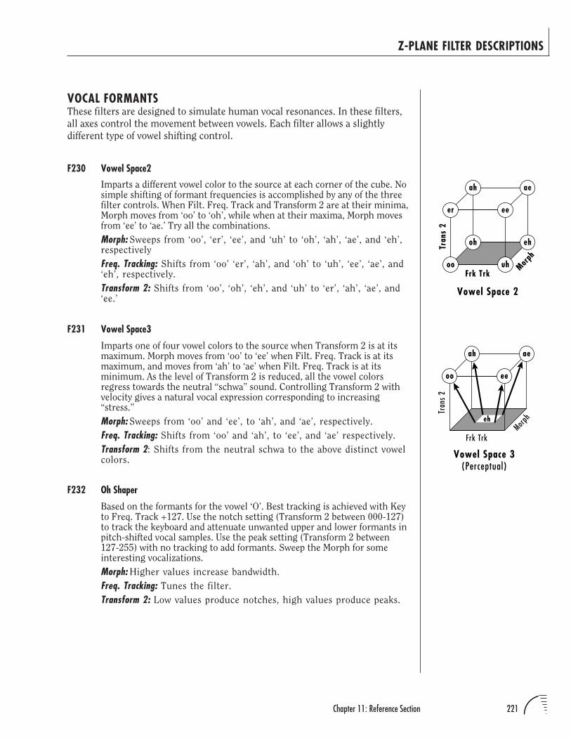
221Chapter 11: Reference Section
ah ae
Tran
s 2Frk Trk
Morph
eeoo
eh
Vowel Space 3(Perceptual)
Z-PLANE FILTER DESCRIPTIONS
VOCAL FORMANTSThese filters are designed to simulate human vocal resonances. In these filters,
all axes control the movement between vowels. Each filter allows a slightly
different type of vowel shifting control.
F230 Vowel Space2
Imparts a different vowel color to the source at each corner of the cube. Nosimple shifting of formant frequencies is accomplished by any of the threefilter controls. When Filt. Freq. Track and Transform 2 are at their minima,Morph moves from ‘oo’ to ‘oh’, while when at their maxima, Morph movesfrom ‘ee’ to ‘ae.’ Try all the combinations.
Morph: Sweeps from ‘oo’, ‘er’, ‘ee’, and ‘uh’ to ‘oh’, ‘ah’, ‘ae’, and ‘eh’,respectively
Freq. Tracking: Shifts from ‘oo’ ‘er’, ‘ah’, and ‘oh’ to ‘uh’, ‘ee’, ‘ae’, and‘eh’, respectively.
Transform 2: Shifts from ‘oo’, ‘oh’, ‘eh’, and ‘uh’ to ‘er’, ‘ah’, ‘ae’, and‘ee.’
F231 Vowel Space3
Imparts one of four vowel colors to the source when Transform 2 is at itsmaximum. Morph moves from ‘oo’ to ‘ee’ when Filt. Freq. Track is at itsmaximum, and moves from ‘ah’ to ‘ae’ when Filt. Freq. Track is at itsminimum. As the level of Transform 2 is reduced, all the vowel colorsregress towards the neutral “schwa” sound. Controlling Transform 2 withvelocity gives a natural vocal expression corresponding to increasing“stress.”
Morph: Sweeps from ‘oo’ and ‘ee’, to ‘ah’, and ‘ae’, respectively.
Freq. Tracking: Shifts from ‘oo’ and ‘ah’, to ‘ee’, and ‘ae’ respectively.
Transform 2: Shifts from the neutral schwa to the above distinct vowelcolors.
F232 Oh Shaper
Based on the formants for the vowel ‘O’. Best tracking is achieved with Keyto Freq. Track +127. Use the notch setting (Transform 2 between 000-127)to track the keyboard and attenuate unwanted upper and lower formants inpitch-shifted vocal samples. Use the peak setting (Transform 2 between127-255) with no tracking to add formants. Sweep the Morph for someinteresting vocalizations.
Morph: Higher values increase bandwidth.
Freq. Tracking: Tunes the filter.
Transform 2: Low values produce notches, high values produce peaks.
ehoh
ah ae
Tran
s 2
Frk Trk
Morph
uhoo
eeer
Vowel Space 2
222 UltraProteus Operation Manual
Z-PLANE FILTER DESCRIPTIONS
F233 Ah ShaperBased on the formants for the vowel ‘Ah’. Best tracking is achieved withKey to Freq. Track +127. Use the notch setting (Transform 2 between 000-127) to track the keyboard and attenuate unwanted upper and lowerformants in pitch-shifted vocal samples. Use the peak setting (Transform 2between 127-255) with no tracking to add formants.
Morph: Higher values increase bandwidth of filters.
Freq. Tracking: Tunes the filters.
Transform 2: Low values produce notches, high values produce peaks.
F234 Oo ShaperBased on the formants for the vowel ‘Oo’. Best tracking is achieved withKey to Freq. Track +127. Use the notch setting (Transform 2 between 000-127) to track the keyboard and attenuate unwanted upper and lowerformants in pitch-shifted vocal samples. Use the peak setting (Transform 2between 127-255) with no tracking to add formants.
Morph: Higher values increase bandwidth of filters.
Freq. Tracking: Tunes the filters.
Transform 2: Low values produce notches, high values produce peaks.
INSTRUMENT FORMANT FILTERSThese filters are to simulate the resonant characteristics of various types of
instruments. The Frequency Tracking parameter sometimes allows the filter to
track specific harmonics, although this may not normally occur on real
acousticinstruments. The subcategories of instrument formant filters are in the
following order: Keyboards, Strings, Plucked, Wind, Brass, Percussion.
F235 FrmntShaperFilter bands are based on formants.
Morph: Controls bandwidth.
Freq. Tracking: Controls gain and tuning.
Transform 2: Controls overall brightness.
F236 Piano LP.4Designed to work a little better than a simple low pass for enhancingsampled piano velocity response.
Morph: Controls the height and width of the subtle peaks at resonantfrequencies.
Freq. Tracking: Tracks filter frequency response with keyboard. Thisfilter works best with Velocity assigned to Morph ≈+150 (use twopatch cords) and no key to Filt. Freq. Track assigned.
Transform 2: Not Used.
223Chapter 11: Reference Section
Z-PLANE FILTER DESCRIPTIONS
F237 PianoSndBrd
Designed for use with the Stereo Grand Piano, the filters in this cube createa variety of resonances designed to imitate the resonances of both the pianosoundboard, the surrounding wood, and various mic placements. All filtersin this cube are scaled for Keyboard Center, Minimum Morph, MinimumTransform 2. Provides fat, bass-heavy resonances, somewhat like miking apiano from the bottom. Contains lots of wood knock.
Max. Morph, Min. Transform 2: Pronounced mid-range resonances, asthough the soundboard was close-miked near its center without anydirect string sound being picked up.
Min. Morph, Max. Transform 2: Lots of mid and high frequency energy,as though the soundboard was being miked by a contact pickup.Exhibits a pronounced electronic sound.
Max. Morph, Max.Transform 2: Almost pure piano sound, with only a bitof high boost starting at about 8kHz. This is the closest to the soundof the raw sample.
F238 Strike Cube
Designed for use with Aux Envelope or Func. Gen. patched to Morph togive struck or plucked tones. Front of Cube gives max brightness, back ofcube gives sine wave if Frequency Tracking is used. Transform 2 controlsthe amount of this effect and can therefore be used for velocity informa-tion.
Set-Up Instructions: Set Envelope Generator to Morph in RealtimeControllers. Set velocity to Transform 2 in Note-On Controllers forgood velocity response. Set Key Center to C1 and Filt. Freq. Track+64 in order to maintain appropriate pitch tracking. Can also be usedfor upper register brightness.
Morph: Controls brightness and volume.
Freq. Tracking: Provides slight increase in upper register brightness,maintains some harmonic filter tracking.
Transform 2: Controls brightness and volume.
F239 Clav CurvesMorph: At no offset, starts 24dB down at 20Hz and increases gain to 0at ≈800Hz then decreases again until reaching -70dB at 20kHz. Atfull offset, resolves into a series of closely space peaks between 67and 284Hz.
Freq. Tracking: Tracks filter over keyboard range.
Transform 2: Keeps the same frequencies but inverts the lowest fre-quency peak to a notch; higher values produce brighter sounds.
224 UltraProteus Operation Manual
Z-PLANE FILTER DESCRIPTIONS
F240 Symphony
A controlled flanging filter which still allows a simple mellow to brighteffect with velocity.
Set-Up Instructions: Set Ctrl A and Pedal to Morph in Realtime Control-lers. Set Velocity to Transform 2 in Note-On Controllers for timbrechoice. Filt. Freq. Track can be used for upper register brightness orflanging response depending on Morph amount.
Morph: Moves between straight velocity to a flanging effect.
Freq. Tracking: Provides choice of flanging region or response.
Transform 2: Provides straightforward mellow/bright and volumevelocity control.
F241 String Cube
For a good overbright response through velocity on Transform 2, but withthe added possibility of emphasising the 2nd harmonic (first overtone) bymorphing, à la strings.
Set-Up Instructions: Set Wheel to Morph in Realtime Controllers. SetVelocity to Transform 2 in Note-On Controllers for good velocityresponse. Set Key Center to C1 and Key to Filt. Freq. Track +64 inorder to maintain appropriate pitch tracking.
Morph: Controls timbre change; picks out first overtone.
Freq. Tracking: Maintains harmonic filter tracking.
Transform 2: Determines brightness and volume.
F242 Swell Cube
An easy cube for making swell-like pads controlled by wheel (Ctrl A) orpedal (Ctrl D). Ideal for strings or choirs brought in by pedal. Morphcontrols a balanced increase in brightness and volume and Transform 2offers a choice of timbres (vaguely aah to ooh).
Set-Up Instructions: Set Ctrl A and Pedal (Ctrl D) to Morph in RealtimeControllers. Set another controller to Transform 2 in Note-On Con-trollers for timbre choice. Set Key Center to C1 and Key to Filt.Freq. Track +64 in order to maintain appropriate pitch tracking.
Morph: Controls swell in effect. A mixture of brightness and volume.
Freq. Tracking: Maintains harmonic filter tracking.
Transform 2: Controls timbre choice. (aah <> oohish on choir-likeinstruments.)
F243 Quartet.4Morph: Widens bump around 1.6kHz while reducing steepness of low-pass slope.
Freq. Tracking: Tracks filter over 5 octaves.
Transform 2: Not Used.
225Chapter 11: Reference Section
F244 Mellotron.4
Designed for use with strings, voices, flutes, and synth pads, this filterattenuates certain lows and low mids while boosting upper midrangefrequencies to give that unnatural, tweaked Mellotron sound. All filters arescaled for Keyboard Center C1.
Morph: Opens filter to allow the natural sample to come throughunprocessed.
Freq. Tracking: Tunes the filter.
Transform 2: Not Used.
F245 Cello
Designed for certain types of bowed string sounds. Try using Velocity todrive Morph and/or Transform 2 axes.
Morph: Increasing values turn notches into peaks.
Freq. Tracking: Tunes the filter.
Transform 2: Increase for additional brightness.
F246 Key SqueakMorph: At low values, contains a fairly mild low pass slope with slightpeaks at 400, 1200, 4000, 5200, 8800Hz opening to a flat repsonsewith slight peaks at 360, 1280, 4400, 5120 and 8620Hz.
Freq. Tracking: Tracks filter over five octaves of keyboard.
Transform 2: Higher values reduce filtering effect until response is flatat 255.
F247 Pluck.4Morph: Low Pass with steep slope and two bumps at ≈120Hz and≈600Hz which opens to a flat response at higher values.
Freq. Tracking: Tracks filter with keyboard.
Transform 2: Not Used.
F248 Pick It
Designed for acoustic guitar. Assign the wheel to Morph (in the Note-OnControllers) to control pick placement. Assign velocity to Transform 2 fordynamics, and key number to Freq. Track for balance across the guitar’srange.
Morph: Controls filter Q.
Freq. Tracking: Tunes the filter.
Transform 2: Gentle lowpass - higher values open the filter.
Z-PLANE FILTER DESCRIPTIONS
226 UltraProteus Operation Manual
F249 El Pick It
Designed for electric guitar. Assign Ctrl A to Morph (in the Note-OnControllers) to control pick placement. Assign velocity to Transform 2 fordynamics, and key number to Freq. Track for balance across the guitar’srange.
Morph: Controls filter Q.
Freq. Tracking: Tunes the filter.
Transform 2: Gentle lowpass; higher values open the filter.
F250 ElGuit Cube
Designed like the Breath Control cubes to give a complete cutoff of soundin the base position. Transform 2 gives an overbright response for loudplaying. Ideal for constructing brass envelopes with the Function Genera-tor or Aux. Envelopes.
Set-Up Instructions: Set Ctrl A/Pedal to Morph in Realtime Controllers.Set Velocity or Controller to Transform 2 in Note-On Controllers foroverbrightness. Filter Freq. Track must be used for best effect.
Morph: Moves between no-sound to bright.
Freq. Tracking: Maintains cutoff frequency just above fundamental.
Transform 2: Adds overbrightness.
F251 ElGuit Pick
Designed for use with electric guitar, this filter mimics the effect of pickposition on timbre. All 8 filters in this cube are scaled for Keyboard CenterC1. Filter Freq. Track is used to track the filter.
Minimum Morph, Min Transform 2: Represent the pick position very closeto the bridge with the bridge position pickup used. Timbre is sharpand trebly, with very little body in the tone.
Maximum Morph, Min. Transform 2: Represent the pick position far upthe neck (over the fretboard). Timbre is both bassy and trebly, butthere is very little body in the overall tone; sounds as though neckposition pickup is being used.
Minimum Morph, Max. Transform 2: Represent the pick position midwaybetween the bridge and the neck. Tone is more even and has morebody; sounds as though bridge position pickup is being used.
Maximum Morph, Max. Transform 2: Represent the pick position nearerthe base of the neck. Tone has body, but also has some high-end“singing.” Determines neck position pickup used.
Z-PLANE FILTER DESCRIPTIONS
227Chapter 11: Reference Section
F252 Breather 1An easy to adjust filter suitable for using breath control for the simulationof wind and brass instruments etc. Also for keyboard use with breathcontrollers connected. Full effort blow gives more brightness and volume,soft playing gives mellower, quieter sound with optional timbre changewith velocity.
Set-Up Instructions: Set Breath Control (Ctrl B) to Morph in RealtimeControllers. Set Velocity to Transform 2 in Note-On Controllers. SetKey Center to C1 and Key to Filt. Freq. Track +64 in order to main-tain the softplay timbre difference with velocity.
Morph: Controls brightness and volume representing effort of “blow”.
Freq. Tracking: Controls slight increase in upper register brightnessand maintains some harmonic filter tracking.
Transform 2: Changes the timbre colour with soft playing.
F253 Breather 2Like F252 Breather 1 with more exaggerated volume change, less timbrechange with velocity. Full effort blow gives more brightness and volume,soft playing gives mellower, quieter sound.
Set-Up Instructions: Set breath control to Morph in Realtime Control-lers. Set velocity to Transform 2 in Note-On Controllers. Set KeyCenter to C1 and Filt. Freq. Track +64 in order to maintain thesoftplay timbre difference with velocity.
Morph: Determines brightness and volume representing effort of“blow”.
Freq. Tracking: Provides slight increase in upper register brightness,maintains some harmonic filter tracking.
Transform 2: Determines change in timbre density on mid-powerblowing.
F254 WindNoise 1Allows simple tuning and tracking of white noise suitable for mixing/layering with wind instruments. Designed for use with Instrument 344Noise Non-X.
Set-Up Instructions: Set Key Center to C1 & Key to Filt. Tracking +64.
Morph: Controls brightness and volume of noise.
Freq. Tracking: Maintains tuning over pitch.
Transform 2: Provides tuning adjustment.
F255 WindNoise 2Like F254 WindNoise 1 but with a broader less harmonic effect. Designedfor use with Instrument 344 Noise Non-X.
Set-Up Instructions: Set Key Center to C1 & Key to Filter Tracking +64.
Morph: Determines brightness and volume of noise.
Freq. Tracking: Maintains a hint of tuning over pitch.
Transform 2: Controls high end brightness.
Z-PLANE FILTER DESCRIPTIONS
228 UltraProteus Operation Manual
F256 Blow CubeDesigned for use without Aux Envelop or Func Gen patched to Morph.Transform 2 controls the volume and brightness and Morph controls thetimbral character at all velocity levels.
Set-Up Instructions: Set Wheel to Morph in Realtime Controllers. SetVelocity to Transform 2 in Note-On Controllers for good velocityresponse. Key Center must be set to C1 and Key to Filt. Freq. Track+64 in order to maintain appropriate pitch tracking.
Morph: Controls timbre change.
Freq. Tracking: Maintains harmonic filter tracking.
Transform 2: Controls brightness and volume.
F257 OverblowDesigned to simulate overblown woodwind effects.
Morph: Higher values accentuate upper harmonics, attenuate lowerones.
Freq. Tracking: Tunes the filter.
Transform 2: Higher values produce subtler effects.
F258 Wind FilterMorph: At no offset, has a lowpass response with select notches at≈3,5,6,9 and 12kHz and a peak at 1kHz. At 255, has a flatter responsewith notches at ≈200, 300, 550, 800 and 870Hz and peak at 1kHz.
Freq. Tracking: Tracks keyboard.
Transform 2: Larger values reduce filter effect and flatten response.
F259 FlutBreth.4Morph: Peaks at ≈100Hz and ≈1200Hz with a notch at ≈700Hz trans-form into flat response with higher values.
Freq. Tracking: Tracks keyboard.
Transform 2: Not Used.
F260 VClarinet.4Designed to turn any sound into a clarinet, or at least simulate its velocityresponse.
Morph: Controls heights and widths of resonances.
Freq. Tracking: Controls the frequencies of the resonances. AssignVelocity to Morph and Key to Filt. Freq. Track.
Transform 2: Not Used.
F261 New Mute.4Morph: Higher values flatten filter response.
Freq. Tracking: Tunes the filter. Works well for brass muting.
Transform 2: Not Used.
Z-PLANE FILTER DESCRIPTIONS
229Chapter 11: Reference Section
F262 Trempeto.4Morph: At 0 offset, response is a lowpass with bump at ≈50Hz and cut-off before 1000Hz. At 255, filter is flat.
Freq. Tracking: Tracks keyboard.
Transform 2: Not Used.
F263 SfBrzando.4Morph: Starts with a 12dB overall boost except for a dip at ≈140Hz. Athigher values, dip is reduced and boost increased after dip untilflattening at 5kHz.
Freq. Tracking:Transform 2: Not Used.
F264 UduFilter.4
Designed to enhance the velocity response of percussion sounds, especiallythe Udu.
Morph: Contains a single peak at 240Hz with mild roll-off of higherfrequencies at low Morph offsets, becoming flatter with higher Morphoffsets.
Freq. Tracking: Tracks five octaves.
Transform 2: Not Used.
F265 Hip KickMorph: Adjusts slope of low-pass response.
Freq. Tracking: Tunes filters.
Transform 2: Reduces overall lowpass effect.
F266 Cymbal Cube
Useful for simulating the response of a cymbal to changes in drumsticklocation.
Morph: Positions drumstick on cymbal.
Freq. Tracking: Tunes the filter.
Transform 2: Larger values reduce filter effect.
F267 ChimeFlangeMorph and Freq. Tracking: Provide two different sets of peaks andnotches (Filt. Freq. Track uses higher frequencies overall) which bothraise in frequency as values are increased. Cool with Gamelan andvarious bells.
Transform 2: Reduces filter effect.
Z-PLANE FILTER DESCRIPTIONS
230 UltraProteus Operation Manual
MISCELLANEOUS FILTERSA potpourri of unique filters that don't fit in any other category.
F268 CableRing.4
All 4 formants are scaled for Keyboard Center C1. When used with theStereo Grand Piano, the Morph parameter results in a resonant sweep thatultimately goes high enough above the piano’s main frequency range thatthe body of the piano tone comes back though; the filter simply adds aglass-like shimmer to the overall sound; a very resonant, ringing filter. Tryputting the Morph Offset at maximum and assigning negative velocity(about -60) to Morph.
Morph: Sweeps resonant peaks.
Freq. Tracking: Tunes the filter.
Transform 2: Not Used.
F269 TensionWireMorph: Accentuates lower frequencies as values increase.
Freq. Tracking: Eliminates low frequencies as values increased.
Transform 2: Reduces overall filter effect and flattens response.
F270 Auto Clang
Morphing this one puts a couple of very pronounced (and harmonicallyunrelated) peaks and a notch (or vice-versa, depending on setting forTransform 2) into the mix. Good for adding extra overtones to bell patches,but works with a variety of sounds.
Morph: Controls gain.
Freq. Tracking: Tunes the filter.
Transform 2: Controls polarity.
F271 Dragon Claw
Useful for making adjustable horn mutes. Also works well with electricbasses.
Morph: Tracks one set of unevenly-spaced notches from medium tomedium high frequencies.
Freq. Tracking: Tracks another, lower frequency set of unevenly-spacednotches to higher frequency notches.
Transform 2: Reduces overall effect of filter as amount is increased.
Z-PLANE FILTER DESCRIPTIONS
231Chapter 11: Reference Section
F272 Spectra
This filter can produce some fairly metallic sounds when Morph is set highand can result in distortion. Use velocity to control Morph for clangorouseffects. Some interesting digital chiffs can be produced as well. Besttracking is obtained with Key Center C1, and Key to Filt. Freq. Track +127.
Morph: Relatively wide notches become narrow peaks as amount isincreased.
Freq. Tracking: Tunes the filter.
Transform 2: Higher values increase bandwidth.
F273 RippleSheetMorph: Opens low pass response.
Freq. Tracking: Accentuates higher frequencies as values increase.
Transform 2: Reduces overall filter effect. Provides good velocityresponse with the acoustic guitar.
F274 Clear Water
Provides a high frequency sheen to any sound. Transforms perform verysubtly. Transform 2 reduces shimmer effect.
Morph: Modulates high frequency accents.
Freq. Tracking: Tracks Keyboard
Transform 2: Reduces filter effect.
F275 InvisibleMorph: As Morph offset increases, boosts at 70 and 269Hz and cuts at167, 560, and 810Hz reverse polarity; peaks become notches, and viceversa.
Freq. Tracking: Raises frequencies two octaves.
Transform 2: Reduces effect of filter.
F276 Wine GlassMorph: At 0 offset, provides gentle roll-off to 1kHz with peaks at2.5kHz and 18kHz. At 255 offset, provides a cut at 82Hz and a boostat 398Hz with a gradual boost from 5 to 18kHz.
Freq. Tracking: Tracks filter to keyboard.
Transform 2: Reduces overall morph effect.
F277 SnakeCros.4Morph: At 0 offset, provides gentle lowpass cutting frequencies at 431and 810Hz and boosting 640Hz. At full offset, response is flat withcuts at 2.6kHz and 4kHz and a slight boost at 6.7kHz.
Freq. Tracking: Flattens response.
Transform 2: Not Used
Z-PLANE FILTER DESCRIPTIONS
232 UltraProteus Operation Manual
F278 Analog.4Morph: At 0 offset, provides a lowpass rolling off at 2.5kHz with asingle peak at 44Hz. At full offset, provides a flat response with an11.5kHz boost.
Freq. Tracking: Same as Morph.
Transform 2: Not Used
F279 Skrtch Cube
Like F241 String Cube, a good overbright response through velocity onTransform 2, In this filter, Morph offers a choice of “soft play” effects. Inzero position, soft play is very mellow as normally expected. In full Morphposition, soft play is scratchy and bright, like fingernails on a guitar stringor drum.
Set-Up Instructions: Set Wheel to Morphing in Realtime Controllers. SetVelocity to Transform 2 in Note-On Controllers for good response.Set Key Center to C1 and Key to Filt. Freq. Track +64 in order tomaintain appropriate pitch tracking. Should be used to get correctfilter effect but can be used for upper register brightness.
Morph: Controls timbre change, from mellow to scratchy.
Freq. Tracking: Maintains harmonic filter tracking.
Transform 2: Determines brightness and volume.
F280 KitchenSinkMorph: Starts as a mild all-pass boost and results in a large peak at≈130Hz.
Freq. Tracking: Tunes the filter.
Transform 2: Controls polarity and intensity of filter effect. Well-suitedfor sweep effects.
F281 Head Pan 1
Should be used on the primary instrument in conjunction with Head Pan 2on the secondary instrument. Together, these two filter cubes mimic thedirectionally-dependent filtering of the head and pinna (external ear). Incontrast to a conventional pan, the headphone image starts above the head(when the Morph control is at its maximum) and moves lower as it movesto either side. When the Morph control is at its minimum, however, theFilt. Freq. Track control pans between left and right at ear level.
Set-up Instructions: Try assigning velocity to Transform 2 +127, andCtrl D (pedal) to Filt. Freq. Track +127 in Note-On Controllers.Assign Ctrl A to Morph +127 in Real Time Controllers. Initial Pansettings: Primary -7, Secondary +7. Re-trigger notes as controllersare modulated. (Use headphones for maximum effect.)
Morph: Sweeps transform peak and notches from high to very highfrequency.
Freq. Tracking: Reverses left and right filters, regardless of morphinglevel.
Transform 2: Gradually increases brightness and volume.
Z-PLANE FILTER DESCRIPTIONS
TRY THE HEAD PAN FILTERS WITHPERCUSSION INSTRUMENTS.THEY REALLY WORK.
233Chapter 11: Reference Section
F282 Head Pan 2
The same as F281 Head Pan 1 with the Frequency Tracking filters reversedfor the opposite ear.
Morph: Sweeps apparent elevation angle from low to high.
Freq. Tracking: Shifts apparent azimuth from left to right.
Transform 2: Shifts apparent distance from far to near.
F283 Arpeggio
Several peaks are tuned to a series of notes. Increasing the Morph offsetdecreases the gain of lower frequencies, while increasing the gain of higherfrequencies. Best tracking is obtained with Key Center set to C1, and Key toFilt. Freq. Track +127.
Morph: Controls gain of the various peaks.
Freq. Tracking: Tunes the filter.
Transform 2: Higher values increase overall gain of the various peaks.
F284 HeavyFilt.4Morph: Starts (at 0 offset) as a high shelving filter with a boost at2.5kHz and resolves (at 255) to a flat response with dips at 6 and14kHz.
Freq. Tracking: Starts flat until a dip at 4kHz and tracks it up infrequency as offset is increased.
Transform 2: Not Used.
F285 Noiz Cube 2
A series of non-harmonically related filter bands. Can impart a woodyquality to some sounds; nice for organs.
Morph: Controls bandwidth and gain.
Freq. Tracking: Tunes the filter.
Transform 2: Controls polarity.
DISTORTION FILTERSNew and improved distortion filters which allow better control over harmonic
content. Grunge, beautiful grunge!
F286 FeedbackMorph: Increases gain of the overtone; higher values distort.
Freq. Tracking: Tunes the filter.
Transform 2: Adjusts low pass Fc. Use this to add feedback, or a pro-nounced harmonic to an instrument. Best tracking is achieved withKey to Filt. Freq. Track +127.
Z-PLANE FILTER DESCRIPTIONS
234 UltraProteus Operation Manual
F287 AllPoleDist
Maximum shred is obtained with both Morph and Transform 2 set to 255.Use Morph to control character of the distortion, and Transform 2 to adjustamount. Best tracking is obtained with Key Center set to C1, and Key toFilt. Freq. Track +127.
Morph: Higher values increase Q.
Freq. Tracking: Tunes the filter.
Transform 2: Sweeps a single pole.
F288 AllPoleDst2
Warning: This filter can easily overload.
Morph: Sweeps the frequency of a single zero.
Freq. Tracking: Lower settings rolloff highs, higher settings rollofflows.
Transform 2: Higher values increase overall Q.
Z-PLANE FILTER DESCRIPTIONS
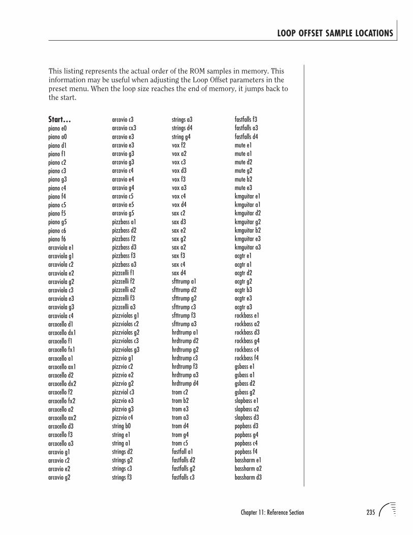
235Chapter 11: Reference Section
LOOP OFFSET SAMPLE LOCATIONS
This listing represents the actual order of the ROM samples in memory. This
information may be useful when adjusting the Loop Offset parameters in the
preset menu. When the loop size reaches the end of memory, it jumps back to
the start.
Start…piano e0piano a0piano d1piano f1piano c2piano c3piano g3piano c4piano f4piano c5piano f5piano g5piano c6piano f6arcoviola e1arcoviola g1arcoviola c2arcoviola e2arcoviola g2arcoviola c3arcoviola e3arcoviola g3arcoviola c4arcocello d1arcocello dx1arcocello f1arcocello fx1arcocello a1arcocello ax1arcocello d2arcocello dx2arcocello f2arcocello fx2arcocello a2arcocello ax2arcocello d3arcocello f3arcocello a3arcovio g1arcovio c2arcovio e2arcovio g2
arcovio c3arcovio cx3arcovio e3arcovio e3arcovio g3arcovio g3arcovio c4arcovio e4arcovio g4arcovio c5arcovio e5arcovio g5pizzbass a1pizzbass d2pizzbass f2pizzbass d3pizzbass f3pizzbass a3pizzcelli f1pizzcelli f2pizzcelli a2pizzcelli f3pizzcelli a3pizzviolas g1pizzviolas c2pizzviolas g2pizzviolas c3pizzviolas g3pizzvio g1pizzvio c2pizzvio e2pizzvio g2pizzviol c3pizzvio e3pizzvio g3pizzvio c4string b0string e1string a1strings d2strings g2strings c3strings f3
strings a3strings d4string g4vox f2vox a2vox c3vox d3vox f3vox a3vox c4vox d4sax c2sax d3sax e2sax g2sax a2sax f3sax c4sax d4sfttrump a1sfttrump d2sfttrump g2sfttrump c3sfttrump f3sfttrump a3hrdtrump a1hrdtrump d2hrdtrump g2hrdtrump c3hrdtrump f3hrdtrump a3hrdtrump d4trom c2trom b2trom e3trom a3trom d4trom g4trom c5fastfall a1fastfalls d2fastfalls g2fastfalls c3
fastfalls f3fastfalls a3fastfalls d4mute e1mute a1mute d2mute g2mute b2mute e3kmguitar e1kmguitar a1kmguitar d2kmguitar g2kmguitar b2kmguitar e3kmguitar a3acgtr e1acgtr a1acgtr d2acgtr g2acgtr b3acgtr e3acgtr a3rockbass e1rockbass a2rockbass d3rockbass g4rockbass c4rockbass f4gsbass e1gsbass a1gsbass d2gsbass g2slapbass e1slapbass a2slapbass d3popbass d3popbass g4popbass c4popbass f4bassharm e1bassharm a2bassharm d3
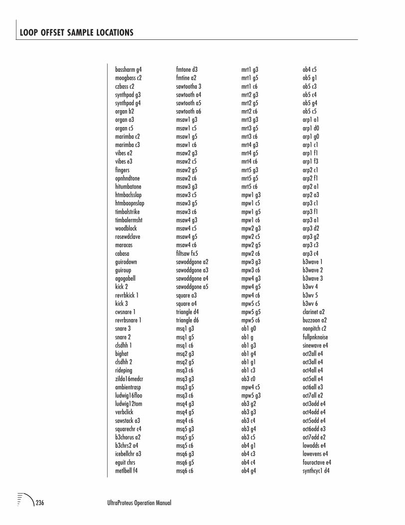
236 UltraProteus Operation Manual
LOOP OFFSET SAMPLE LOCATIONS
bassharm g4moogbass c2czbass c2synthpad g3synthpad g4organ b2organ a3organ c5marimba c2marimba c3vibes e2vibes e3fingersopnhndtonehitumbatonehtmbaclsslaphtmbaopnslaptimbalstriketimbalermshtwoodblockrosewdclavemaracascabasaguirodownguiroupagogobellkick 2revrbkick 1kick 3cwsnare 1revrbsnare 1snare 3snare 2clsdhh 1bighatclsdhh 2ridepingzilda16medcrambientraspludwig16flooludwig12tomverbclicksawstack a3squarechr c4b3chorus a2b3chrs2 a4icebellchr a3eguit chrsmetlbell f4
fmtone d3fmtine a2sawtootha 3sawtooth a4sawtooth a5sawtooth a6msaw1 g3msaw1 c5msaw1 g5msaw1 c6msaw2 g3msaw2 c5msaw2 g5msaw2 c6msaw3 g3msaw3 c5msaw3 g5msaw3 c6msaw4 g3msaw4 c5msaw4 g5msaw4 c6filtsaw fx5sawoddgone a2sawoddgone a3sawoddgone a4sawoddgone a5square a3square a4triangle d4triangle d6msq1 g3msq1 g5msq1 c6msq2 g3msq2 g5msq3 c6msq3 g3msq3 g5msq3 c6msq4 g3msq4 g5msq4 c6msq5 g3msq5 g5msq5 c6msq6 g3msq6 g5msq6 c6
mrt1 g3mrt1 g5mrt1 c6mrt2 g3mrt2 g5mrt2 c6mrt3 g3mrt3 g5mrt3 c6mrt4 g3mrt4 g5mrt4 c6mrt5 g3mrt5 g5mrt5 c6mpw1 g3mpw1 c5mpw1 g5mpw1 c6mpw2 g3mpw2 c5mpw2 g5mpw2 c6mpw3 g3mpw3 c6mpw4 g3mpw4 g5mpw4 c6mpw5 c5mpw5 g5mpw5 c6ob1 g0ob1 gob1 g3ob1 g4ob1 g1ob1 c3ob3 c0mpw4 c5mpw5 g3ob3 g2ob3 g3ob3 c4ob3 g4ob3 c5ob4 g1ob4 c3ob4 c4ob4 g4
ob4 c5ob5 g1ob5 c3ob5 c4ob5 g4ob5 c5arp1 a1arp1 d0arp1 g0arp1 c1arp1 f1arp1 f3arp2 c1arp2 f1arp2 a1arp2 a3arp3 c1arp3 f1arp3 a1arp3 d2arp3 g2arp3 c3arp3 c4b3wave 1b3wave 2b3wave 3b3wv 4b3wv 5b3wv 6clarinet a2buzzoon a2nonpitch c2fullpnknoisesinewave e4oct2all e4oct3all e4oct4all e4oct5all e4oct6all e3oct7all e2oct3odd e4oct4odd e4oct5odd e4oct6odd e3oct7odd e2lowodds e4lowevens e4fouroctave e4synthcyc1 d4
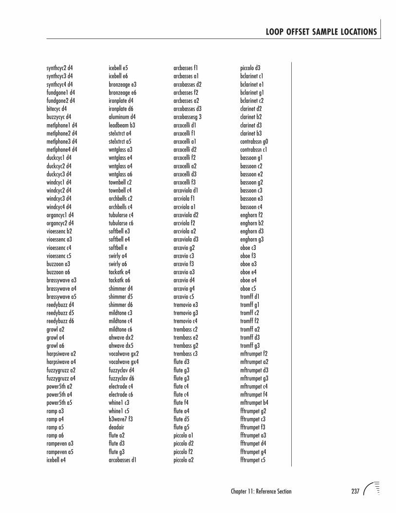
237Chapter 11: Reference Section
LOOP OFFSET SAMPLE LOCATIONS
synthcyc2 d4synthcyc3 d4synthcyc4 d4fundgone1 d4fundgone2 d4bitecyc d4buzzycyc d4metlphone1 d4metlphone2 d4metlphone3 d4metlphone4 d4duckcyc1 d4duckcyc2 d4duckcyc3 d4windcyc1 d4windcyc2 d4windcyc3 d4windcyc4 d4organcyc1 d4organcyc2 d4vioessenc b2vioessenc a3vioessenc c4vioessenc c5buzzoon a3buzzoon a6brassywave a3brassywave a4brassywave a5reedybuzz d4reedybuzz d5reedybuzz d6growl a2growl a4growl a6harpsiwave a2harpsiwave a4fuzzygruzz a2fuzzygruzz a4power5th a2power5th a4power5th a5ramp a3ramp a4ramp a5ramp a6rampeven a3rampeven a5icebell e4
piccolo d3bclarinet c1bclarinet e1bclarinet g1bclarinet c2clarinet d2clarinet b2clarinet d3clarinet b3contrabssn g0contrabssn c1bassoon g1bassoon c2bassoon e2bassoon g2bassoon c3bassoon e3bassoon c4enghorn f2enghorn b2enghorn d3enghorn g3oboe c3oboe f3oboe a3oboe e4oboe a4oboe c5tromff d1tromff g1tromff c2tromff f2tromff a2tromff d3tromff g3mftrumpet f2mftrumpet a2mftrumpet d3mftrumpet g3mftrumpet c4mftrumpet f4mftrumpet b4fftrumpet g2fftrumpet c3fftrumpet f3fftrumpet a3fftrumpet d4fftrumpet g4fftrumpet c5
icebell e5icebell e6bronzeage e3bronzeage e6ironplate d4ironplate d6aluminum d4leadbeam b3stelxtrct a4stelxtrct a5wntglass a3wntglass e4wntglass a4wntglass a6townbell c2townbell c4orchbells c2orchbells c4tubularse c4tubularse c6softbell e3softbell e4softbell eswirly a4swirly a6tackatk a4tackatk a6shimmer d4shimmer d5shimmer d6mildtone c3mildtone c4mildtone c6ahwave dx2ahwave dx5vocalwave gx2vocalwave gx4fuzzyclav d4fuzzyclav d6electrode c4electrode c6whine1 c3whine1 c5b3wave7 f3deadairflute a2flute d3flute g3arcobasses d1
arcbasses f1arcbasses a1arcobasses d2arcbasses f2arcbasses a2arcobasses d3arcobassesg 3arcocelli d1arcocelli f1arcocelli a1arcocelli d2arcocelli f2arcocelli a2arcocelli d3arcocelli f3arcoviola d1arcviola f1arcviola a1arcoviola d2arcviola f2arcviola a2arcoviola d3arcovio g2arcovio c3arcovio f3arcovio a3arcovio d4arcovio g4arcovio c5tremovio e3tremovio g3tremovio c4trembass c2trembass e2trembass g2trembass c3flute d3flute g3flute g3flute c4flute c4flute f4flute a4flute d5flute g5piccolo a1piccolo d2piccolo f2piccolo a2

238 UltraProteus Operation Manual
harmmute g2harmonmute c3harmonmute e3harmmute g3harmmute c4harmmute e4harmmute a4frhornmf d2frhornmf g2frhornmf c3frhornmf f3frhornmf a3frhornmf d4frenchhorn d2frenchhorn f2frenchhorn c3frenchhorn f3frenchhrn a3frenchhrn d4tuba f0tuba d1tuba f1tuba a1xylo e4xylo g4xylo e5celeste e5triangle ax3bassdrum g1snaresnarerollrimshotrimclicktimpani a1piatti f3brasstambtamtam c4tempblock e4glock g4tubbell d4templeblck b4troubharp e2troubharp c3troubharp f3troubhrp a3irishharp c3irishharp f3irishharp a3dlcmr c2
LOOP OFFSET SAMPLE LOCATIONS
banyatonebanyaslapbanyahittablatonetablamuteatablamutebtablamutectablaopenclapprstikrosewdbassrosewdtickrosewdharmrosewdfngrtanzshakerbonangkenonglowtumbatonequintclsdslpquintotonequicadwnstrkquicahitonecowbellbongo rimbongo tonevibraloopsprngysplashridebellkmzildjian19chsambawhistleclave808snare808bd808sidestick808cowbell808clsdhat808openhat808claps808ridecym808deadairdeadairdeadairmultfrm1ckaleidoscope…End
chanter a1chanter g1bullroarersprtcatchrdigeridoodigeritonedigeriscrmjewsharp ajewsharp bjewsharp cjewsharp dplexislap cbronzesaronsuwukgongchinagongnepalcymbltibetbowlsteeldrumcrotales d5hulastickplexitoneplexislapaplexislapbsurdoopenlikembe f3likembebuz d3log drumsurdomutedeffslapdeffmutebendiropenreqopenreqslapcastanetmaraca amaraca bmaraca cmaraca dudutoneudureleaseudufingeruduslapiputoneipuslapenutonebatatonebatamutebataslapcrickets
dlcmr c3dlcmr b3koto g2koto c3koto g3banjo g2banjo d3banjo g3banjo d4tar d2guitar g1guitar c2guitar f2guitar b2guitar e3sitar d4tamboura c2bwdpsaltry e3waterphone 1waterphone 2accord f2accord a2accord f3harmonica d2harmonica a2harmonica vb d2harmonica vb a2harmonica vb c3harmonica vb f3harmonica vb a3harmonica vb c3harmonica vb d3harmonica vb a4harmonica vb c5mizmars a3shenai g4penwhistl g1ocarina f2shofarloopshofarrlsesiku e2siku b2siku f3charmerloopneyflute b2neyflute f3neyflute b3neyflute a4bagpipedrn a
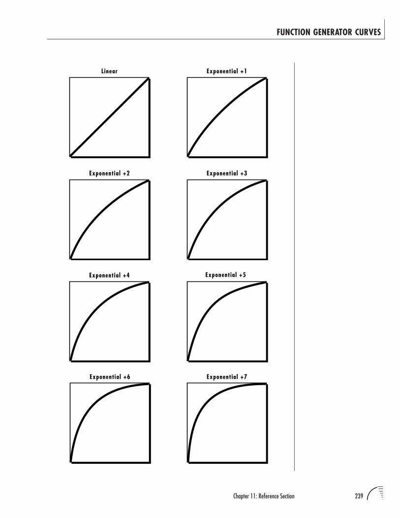
239Chapter 11: Reference Section
FUNCTION GENERATOR CURVES
Linear Exponential +1
Exponential +2 Exponential +3
Exponential +4 Exponential +5
Exponential +6 Exponential +7
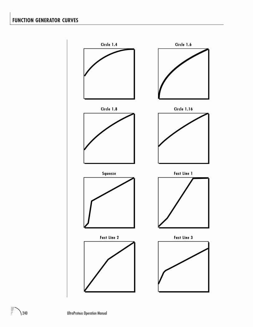
240 UltraProteus Operation Manual
FUNCTION GENERATOR CURVES
Circ le 1.4 Circ le 1.6
Circ le 1.8 Circ le 1.16
Squeeze Fast Line 1
Fast Line 2 Fast Line 3
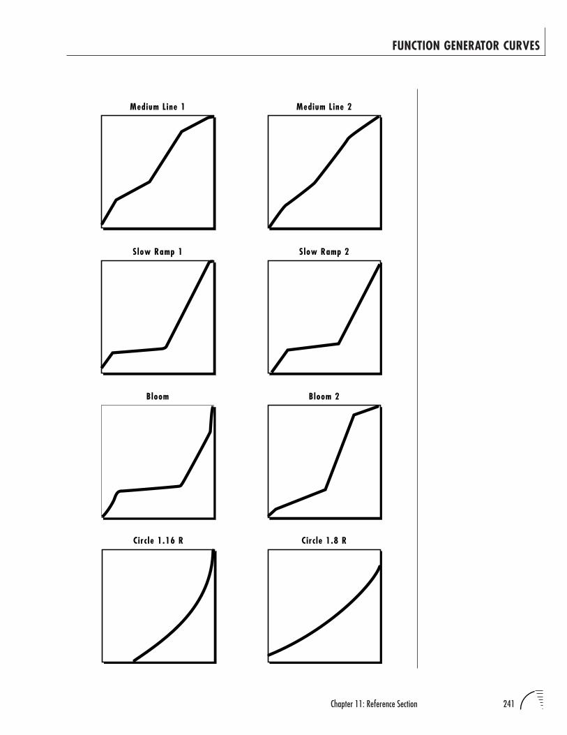
241Chapter 11: Reference Section
FUNCTION GENERATOR CURVES
Medium Line 1 Medium Line 2
Slow Ramp 1 Slow Ramp 2
Bloom Bloom 2
Circ le 1.16 R Circ le 1.8 R
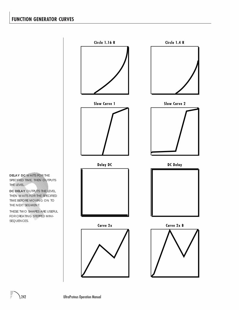
242 UltraProteus Operation Manual
FUNCTION GENERATOR CURVES
Circ le 1.16 R Circ le 1.4 R
Slow Curve 1 Slow Curve 2
DC DelayDelay DC
Curve 2x Curve 2x B
DELAY DC WAITS FOR THESPECIFIED TIME, THEN OUTPUTSTHE LEVEL.
DC DELAY OUTPUTS THE LEVEL,THEN WAITS FOR THE SPECIFIEDTIME BEFORE MOVING ON TOTHE NEXT SEGMENT.
THESE TWO SHAPES ARE USEFULFOR CREATING STEPPED MINI-SEQUENCES.
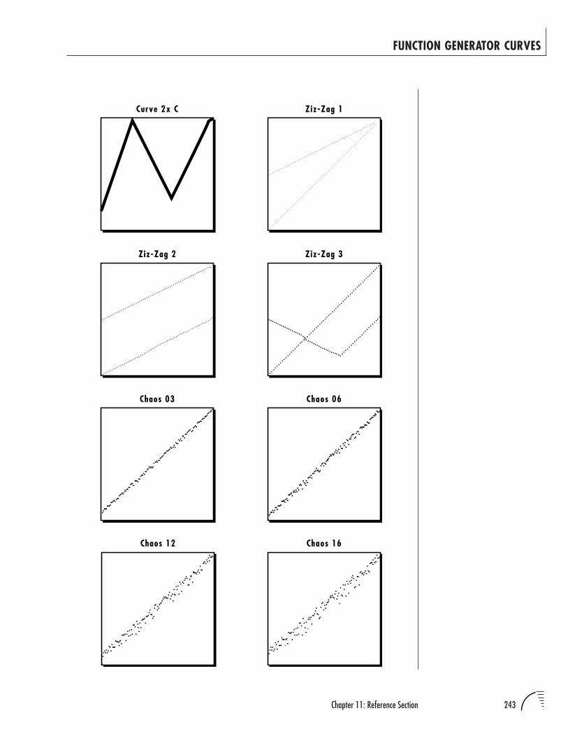
243Chapter 11: Reference Section
FUNCTION GENERATOR CURVES
Curve 2x C Ziz-Zag 1
Ziz-Zag 2 Ziz-Zag 3
Chaos 03 Chaos 06
Chaos 12 Chaos 16
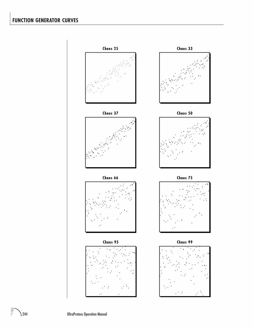
244 UltraProteus Operation Manual
FUNCTION GENERATOR CURVES
Chaos 25 Chaos 33
Chaos 37 Chaos 50
Chaos 66 Chaos 75
Chaos 95 Chaos 99
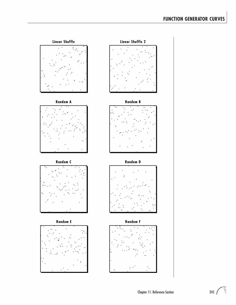
245Chapter 11: Reference Section
FUNCTION GENERATOR CURVES
Linear Shuffle Linear Shuffle 2
Random BRandom A
Random C Random D
Random E Random F
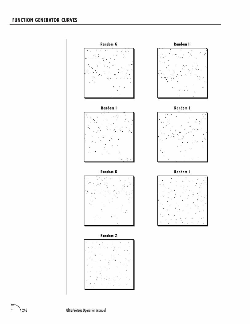
246 UltraProteus Operation Manual
FUNCTION GENERATOR CURVES
Random G Random H
Random I Random J
Random K
Random Z
Random L
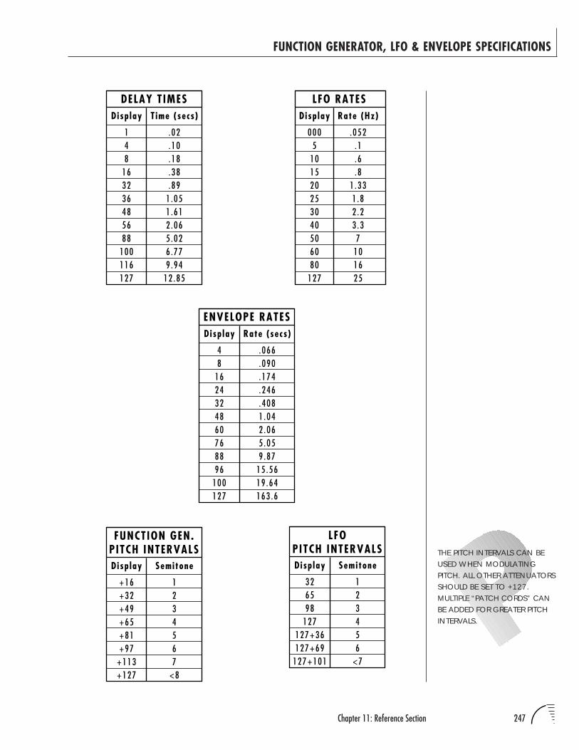
247Chapter 11: Reference Section
FUNCTION GENERATOR, LFO & ENVELOPE SPECIFICATIONS
DELAY T IMES
148
163236485688
100116127
.02
.10
.18
.38
.891 .051 .612 .065 .026 .779 .94
12 .85
Disp lay T ime (secs )
FUNCTION GEN.PITCH INTERVALS
+16+32+49+65+81+97
+113+127
1234567
<8
Disp lay Semitone
LFOPITCH INTERVALS
326598
127127+36127+69
127+101
123456
<7
Disp lay Semitone
LFO RATES
0005
101520253040506080
127
.052.1.6.8
1 .331 .82 .23 .37
101625
Disp lay Rate (Hz)
THE PITCH INTERVALS CAN BEUSED WHEN MODULATINGPITCH. ALL OTHER ATTENUATORSSHOULD BE SET TO +127.MULTIPLE “PATCH CORDS” CANBE ADDED FOR GREATER PITCHINTERVALS.
ENVELOPE RATES
48
1624324860768896
100127
.066
.090
.174
.246
.4081 .042 .065 .059 .87
15 .5619 .64163 .6
Disp lay Rate (secs )
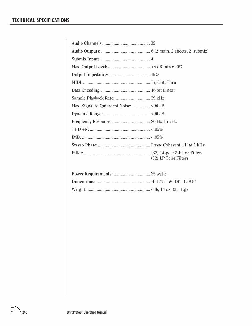
248 UltraProteus Operation Manual
TECHNICAL SPECIFICATIONS
Audio Channels: ......................................... 32
Audio Outputs: ........................................... 6 (2 main, 2 effects, 2 submix)
Submix Inputs: ........................................... 4
Max. Output Level: ..................................... +4 dB into 600Ω
Output Impedance: .................................... 1kΩ
MIDI: ........................................................... In, Out, Thru
Data Encoding: ........................................... 16 bit Linear
Sample Playback Rate: .............................. 39 kHz
Max. Signal to Quiescent Noise: ................ >90 dB
Dynamic Range: ......................................... >90 dB
Frequency Response: ................................. 20 Hz-15 kHz
THD +N: ..................................................... <.05%
IMD: ............................................................ <.05%
Stereo Phase: .............................................. Phase Coherent ±1˚ at 1 kHz
Filter: .......................................................... (32) 14-pole Z-Plane Filters
(32) LP Tone Filters
Power Requirements: ................................ 25 watts
Dimensions: ............................................... H: 1.75" W: 19" L: 8.5"
Weight: ....................................................... 6 lb, 14 oz (3.1 Kg)
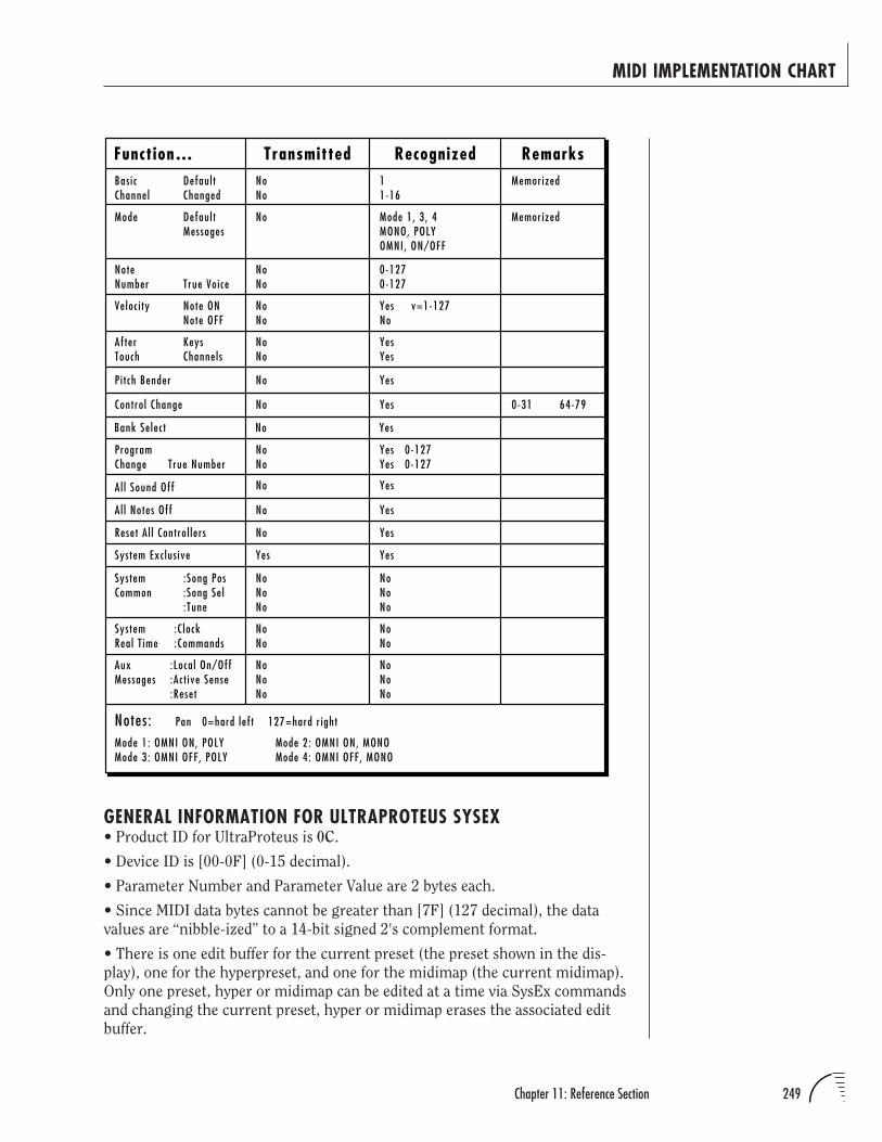
249Chapter 11: Reference Section
MIDI IMPLEMENTATION CHART
GENERAL INFORMATION FOR ULTRAPROTEUS SYSEX• Product ID for UltraProteus is 0C.
• Device ID is [00-0F] (0-15 decimal).
• Parameter Number and Parameter Value are 2 bytes each.
• Since MIDI data bytes cannot be greater than [7F] (127 decimal), the data
values are “nibble-ized” to a 14-bit signed 2's complement format.
• There is one edit buffer for the current preset (the preset shown in the dis-
play), one for the hyperpreset, and one for the midimap (the current midimap).
Only one preset, hyper or midimap can be edited at a time via SysEx commands
and changing the current preset, hyper or midimap erases the associated edit
buffer.
Transmitted Recognized RemarksBas icChannel
Defaul tChanged
Mode Defaul tMessages
NoteNumber True Voice
Veloc i ty Note ONNote OFF
AfterTouch
KeysChannels
P i t ch Bender
Contro l Change
ProgramChange True Number
System Exc lus ive
SystemCommon
:Song Pos:Song Se l:Tune
SystemReal T ime
:C lock:Commands
AuxMessages
:Loca l On/Off:Ac t ive Sense:Reset
NoNo
11-16
Memorized
No Mode 1, 3 , 4MONO, POLYOMNI, ON/OFF
Memorized
NoNo
0-1270-127
NoNo
YesNo
v=1-127
NoNo
YesYes
No Yes
No Yes
NoNo
Yes 0-127Yes 0-127
Yes Yes
NoNoNo
NoNoNo
NoNo
NoNo
NoNoNo
NoNoNo
Notes : Pan 0=hard lef t 127=hard r ight
Function…
Mode 1: OMNI ON, POLYMode 3: OMNI OFF, POLY
Mode 2: OMNI ON, MONOMode 4: OMNI OFF, MONO
0-31
Bank Se lec t No Yes
64-79
Al l Sound Off
Reset A l l Contro l lers
No Yes
No Yes
Al l Notes Off No Yes
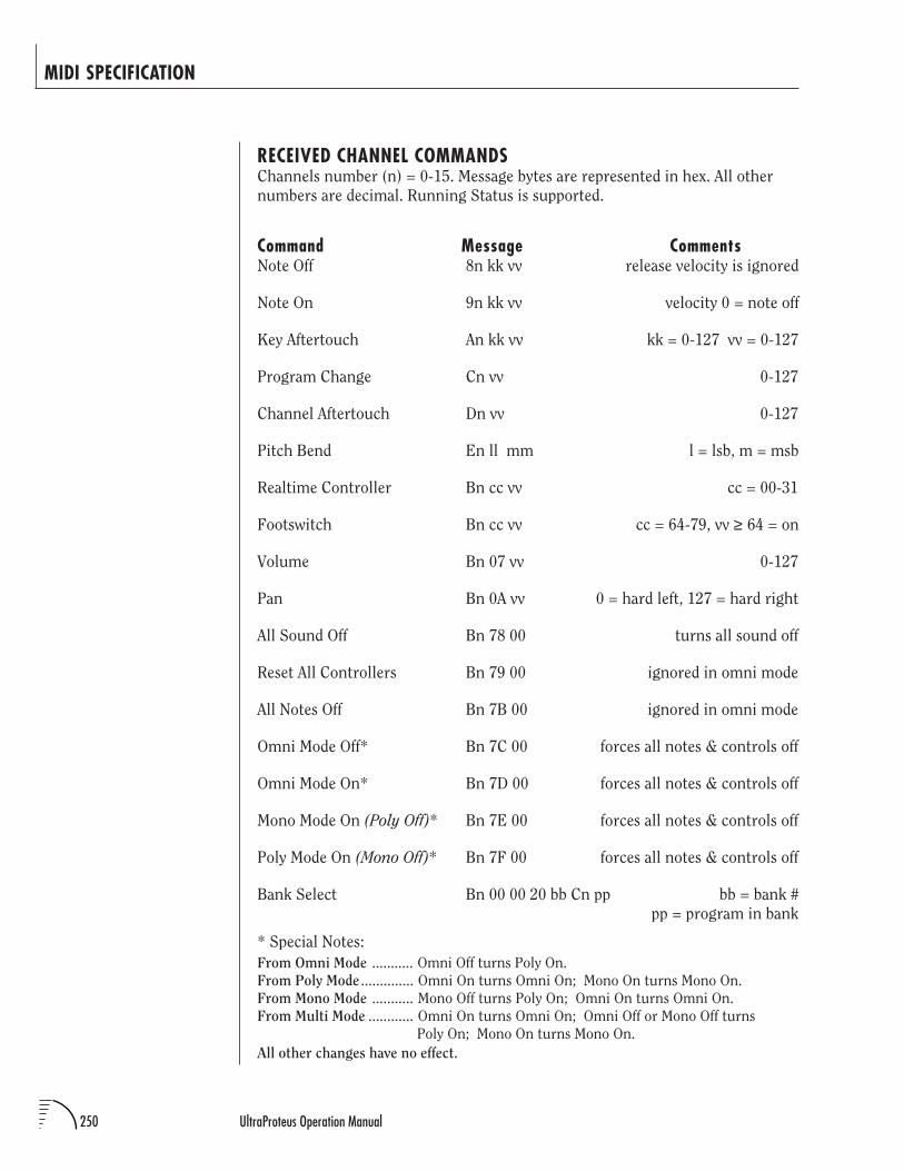
250 UltraProteus Operation Manual
RECEIVED CHANNEL COMMANDSChannels number (n) = 0-15. Message bytes are represented in hex. All other
numbers are decimal. Running Status is supported.
Command Message CommentsNote Off 8n kk vv release velocity is ignored
Note On 9n kk vv velocity 0 = note off
Key Aftertouch An kk vv kk = 0-127 vv = 0-127
Program Change Cn vv 0-127
Channel Aftertouch Dn vv 0-127
Pitch Bend En ll mm l = lsb, m = msb
Realtime Controller Bn cc vv cc = 00-31
Footswitch Bn cc vv cc = 64-79, vv ≥ 64 = on
Volume Bn 07 vv 0-127
Pan Bn 0A vv 0 = hard left, 127 = hard right
All Sound Off Bn 78 00 turns all sound off
Reset All Controllers Bn 79 00 ignored in omni mode
All Notes Off Bn 7B 00 ignored in omni mode
Omni Mode Off* Bn 7C 00 forces all notes & controls off
Omni Mode On* Bn 7D 00 forces all notes & controls off
Mono Mode On (Poly Off)* Bn 7E 00 forces all notes & controls off
Poly Mode On (Mono Off)* Bn 7F 00 forces all notes & controls off
Bank Select Bn 00 00 20 bb Cn pp bb = bank #
pp = program in bank
* Special Notes:
From Omni Mode ........... Omni Off turns Poly On.
From Poly Mode .............. Omni On turns Omni On; Mono On turns Mono On.
From Mono Mode ........... Mono Off turns Poly On; Omni On turns Omni On.
From Multi Mode ............ Omni On turns Omni On; Omni Off or Mono Off turns
Poly On; Mono On turns Mono On.
All other changes have no effect.
MIDI SPECIFICATION
251Chapter 11: Reference Section
MIDI SPECIFICATION
MIDI SYSEX COMMANDSFor system exclusive commands, the following format is used:
F0 System Exclusive Status Byte
18 E-mu ID Byte
0C Product ID Byte (will also respond to ID 04 - Proteus)
dd Device ID Byte
cc Command Byte
... Data Bytes
F7 EOX
SysEx EditingPreset and setup parameters may be edited individually using system exclusive
commands. The preset being edited is the active preset (the preset on the basic
or global channel and the one which is shown in the LCD). The value of a given
parameter may be changed by sending a parameter value command. The value
of a parameter may be read by sending a parameter value request, to which the
machine will respond by sending back the parameter value. Please note that
there is only one edit buffer
All SysEx bytes are displayed in Hex, unless specified otherwise. All comment
numbers are displayed in decimal, unless specified otherwise.
Two MIDI bytes (lsb, msb) are required for each 14 bit data word. Bits 0-6 are
sent first, followed by bits 7-13 in the next MIDI byte. All data words are signed
2's complement values with sign-extension out to the most significant bit (bit
13). This convention applies to all data words, regardless of the parameter's
value range.
Preset data may also be transmitted or received in a single block (one complete
preset) using system exclusive commands. A preset data request may be issued
by a host computer, to which the machine will respond sending the data block
for the requested preset. Conversely, the computer may send new preset data
which will replace the specified preset currently in the machine. Additionally, a
front panel command will transmit one or all user presets for backup onto an
external sequencer. These presets may be restored by simply playing back the
sequence into the machine.
Warning: When transferring preset banks and tuning table data back and forth
from UltraProteus to a computer, the data should be recorded as you would a
regular sequence. Sending the data in one huge chunk will clog the input buffer
on UltraProteus unless a time period of approximately 100 mS is inserted
between each preset. The SysEx Packet Delay feature in the Master menu can be
used to slow down the data rate when the computer's input buffer is being
clogged.
ULTRAPROTEUS WILL RECEIVEPROTEUS 1/2/3 PRESETS (IFENABLED IN THE MASTERMENU). IT WILL FILL IN THE EXTRAPARAMETERS WITH DEFAULTVALUES AND MATCHINSTRUMENT NUMBERS TOEITHER THE EXACT INSTRUMENTOR TO THE ULTRAPROTEUSEQUIVALENT. PRESET LINKS WILLNOT BE TRANSFERRED.
THERE IS ONLY ONE EDITBUFFER EACH FOR THECURRENT PRESET, THECURRENT HYPERPRESET, ANDTHE CURRENT MIDIMAP.
ONLY ONE PRESET,HYPERPRESET OR MIDIMAPCAN BE EDITED AT A TIME VIASYSEX COMMANDS ANDCHANGING THE CURRENTPRESET, HYPER OR MIDIMAPERASES THE ASSOCIATED EDITBUFFER.
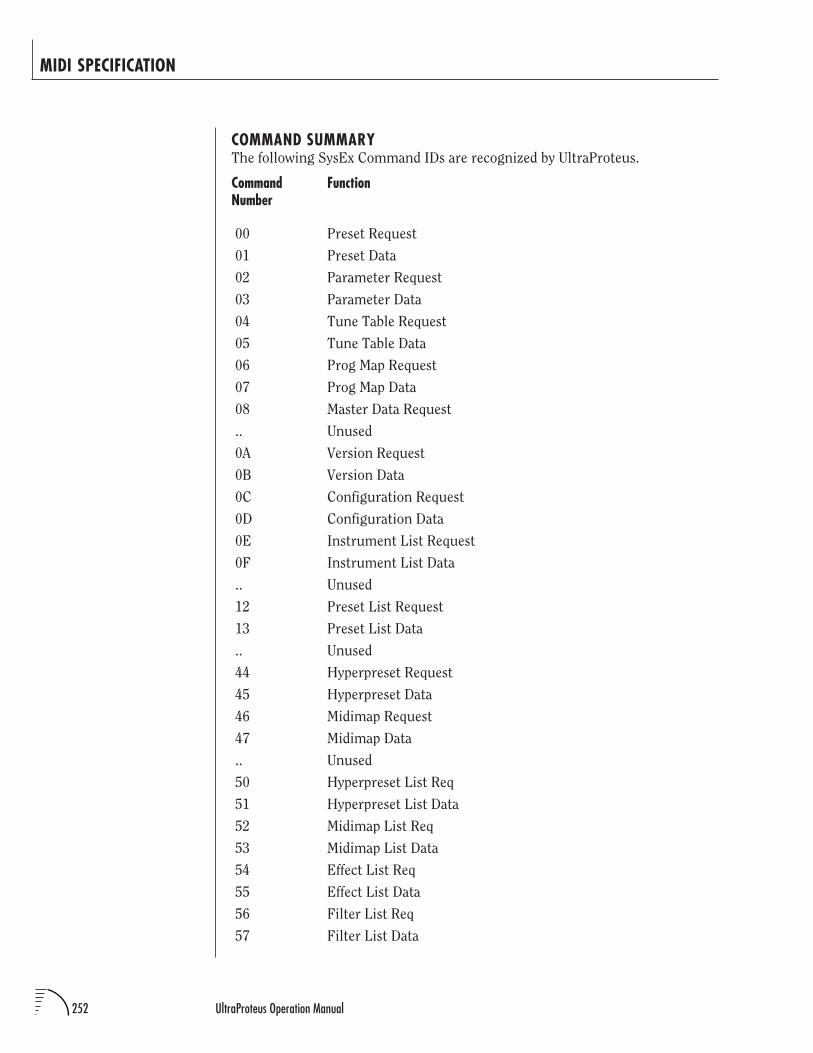
252 UltraProteus Operation Manual
COMMAND SUMMARYThe following SysEx Command IDs are recognized by UltraProteus.
Command FunctionNumber
00 Preset Request
01 Preset Data
02 Parameter Request
03 Parameter Data
04 Tune Table Request
05 Tune Table Data
06 Prog Map Request
07 Prog Map Data
08 Master Data Request
.. Unused
0A Version Request
0B Version Data
0C Configuration Request
0D Configuration Data
0E Instrument List Request
0F Instrument List Data
.. Unused
12 Preset List Request
13 Preset List Data
.. Unused
44 Hyperpreset Request
45 Hyperpreset Data
46 Midimap Request
47 Midimap Data
.. Unused
50 Hyperpreset List Req
51 Hyperpreset List Data
52 Midimap List Req
53 Midimap List Data
54 Effect List Req
55 Effect List Data
56 Filter List Req
57 Filter List Data
MIDI SPECIFICATION
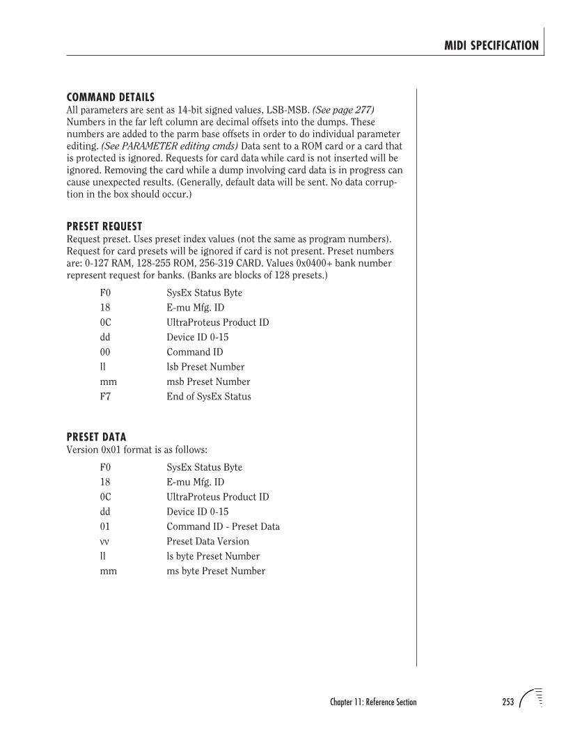
253Chapter 11: Reference Section
COMMAND DETAILSAll parameters are sent as 14-bit signed values, LSB-MSB. (See page 277)
Numbers in the far left column are decimal offsets into the dumps. These
numbers are added to the parm base offsets in order to do individual parameter
editing. (See PARAMETER editing cmds) Data sent to a ROM card or a card that
is protected is ignored. Requests for card data while card is not inserted will be
ignored. Removing the card while a dump involving card data is in progress can
cause unexpected results. (Generally, default data will be sent. No data corrup-
tion in the box should occur.)
PRESET REQUESTRequest preset. Uses preset index values (not the same as program numbers).
Request for card presets will be ignored if card is not present. Preset numbers
are: 0-127 RAM, 128-255 ROM, 256-319 CARD. Values 0x0400+ bank number
represent request for banks. (Banks are blocks of 128 presets.)
F0 SysEx Status Byte
18 E-mu Mfg. ID
0C UltraProteus Product ID
dd Device ID 0-15
00 Command ID
ll lsb Preset Number
mm msb Preset Number
F7 End of SysEx Status
PRESET DATAVersion 0x01 format is as follows:
F0 SysEx Status Byte
18 E-mu Mfg. ID
0C UltraProteus Product ID
dd Device ID 0-15
01 Command ID - Preset Data
vv Preset Data Version
ll ls byte Preset Number
mm ms byte Preset Number
MIDI SPECIFICATION
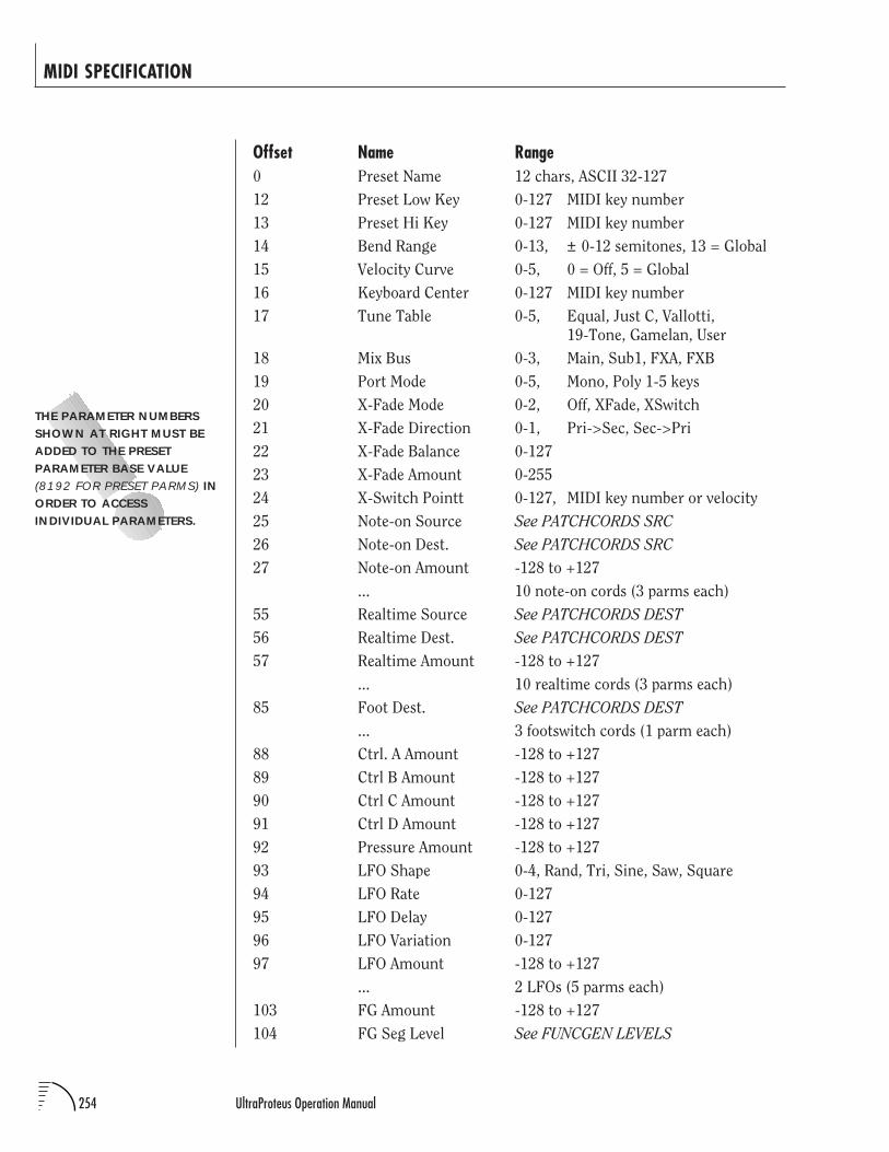
254 UltraProteus Operation Manual
MIDI SPECIFICATION
Offset Name Range0 Preset Name 12 chars, ASCII 32-127
12 Preset Low Key 0-127 MIDI key number
13 Preset Hi Key 0-127 MIDI key number
14 Bend Range 0-13, ± 0-12 semitones, 13 = Global
15 Velocity Curve 0-5, 0 = Off, 5 = Global
16 Keyboard Center 0-127 MIDI key number
17 Tune Table 0-5, Equal, Just C, Vallotti,
19-Tone, Gamelan, User
18 Mix Bus 0-3, Main, Sub1, FXA, FXB
19 Port Mode 0-5, Mono, Poly 1-5 keys
20 X-Fade Mode 0-2, Off, XFade, XSwitch
21 X-Fade Direction 0-1, Pri->Sec, Sec->Pri
22 X-Fade Balance 0-127
23 X-Fade Amount 0-255
24 X-Switch Pointt 0-127, MIDI key number or velocity
25 Note-on Source See PATCHCORDS SRC
26 Note-on Dest. See PATCHCORDS SRC
27 Note-on Amount -128 to +127
... 10 note-on cords (3 parms each)
55 Realtime Source See PATCHCORDS DEST
56 Realtime Dest. See PATCHCORDS DEST
57 Realtime Amount -128 to +127
... 10 realtime cords (3 parms each)
85 Foot Dest. See PATCHCORDS DEST
... 3 footswitch cords (1 parm each)
88 Ctrl. A Amount -128 to +127
89 Ctrl B Amount -128 to +127
90 Ctrl C Amount -128 to +127
91 Ctrl D Amount -128 to +127
92 Pressure Amount -128 to +127
93 LFO Shape 0-4, Rand, Tri, Sine, Saw, Square
94 LFO Rate 0-127
95 LFO Delay 0-127
96 LFO Variation 0-127
97 LFO Amount -128 to +127
... 2 LFOs (5 parms each)
103 FG Amount -128 to +127
104 FG Seg Level See FUNCGEN LEVELS
THE PARAMETER NUMBERSSHOWN AT RIGHT MUST BEADDED TO THE PRESETPARAMETER BASE VALUE(8192 FOR PRESET PARMS) INORDER TO ACCESSINDIVIDUAL PARAMETERS.
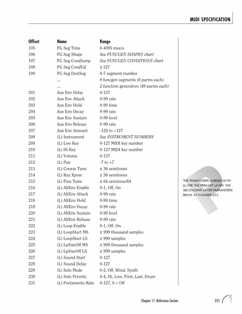
255Chapter 11: Reference Section
MIDI SPECIFICATION
Offset Name Range105 FG Seg Time 0-4095 msecs
106 FG Seg Shape See FUNCGEN SHAPES chart
107 FG Seg CondJump See FUNCGEN CONDITIONS chart
108 FG Seg CondVal ± 127
109 FG Seg DestSeg 0-7 segment number
... 8 funcgen segments (6 parms each)
... 2 function generators (49 parms each)
201 Aux Env Delay 0-127
202 Aux Env Attack 0-99 rate
203 Aux Env Hold 0-99 time
204 Aux Env Decay 0-99 rate
205 Aux Env Sustain 0-99 level
206 Aux Env Release 0-99 rate
207 Aux Env Amount -128 to +127
208 (L) Instrument See INSTRUMENT NUMBERS
209 (L) Low Key 0-127 MIDI key number
210 (L) Hi Key 0-127 MIDI key number
211 (L) Volume 0-127
212 (L) Pan -7 to +7
213 (L) Course Tune ± 36 semitones
214 (L) Key Xpose ± 36 semitones
215 (L) Fine Tune ± 64 semitone/64
216 (L) AltEnv Enable 0-1, Off, On
217 (L) AltEnv Attack 0-99 rate
218 (L) AltEnv Hold 0-99 time
219 (L) AltEnv Decay 0-99 rate
220 (L) AltEnv Sustain 0-99 level
221 (L) AltEnv Release 0-99 rate
222 (L) Loop Enable 0-1, Off, On
223 (L) LoopStart MS ± 999 thousand samples
224 (L) LoopStart LS ± 999 samples
225 (L) LpSizeOff MS ± 999 thousand samples
226 (L) LpSizeOff LS ± 999 samples
227 (L) Sound Start 0-127
228 (L) Sound Delay 0-127
229 (L) Solo Mode 0-2, Off, Wind, Synth
230 (L) Solo Priority 0-4, Hi, Low, First, Last, Drum
231 (L) Portamento Rate 0-127, 0 = Off
THE PARAMETERS LABELED WITH(L) ARE THE PRIMARY LAYER. THESECONDARY LAYER PARAMETERSBEGIN AT NUMBER 243.
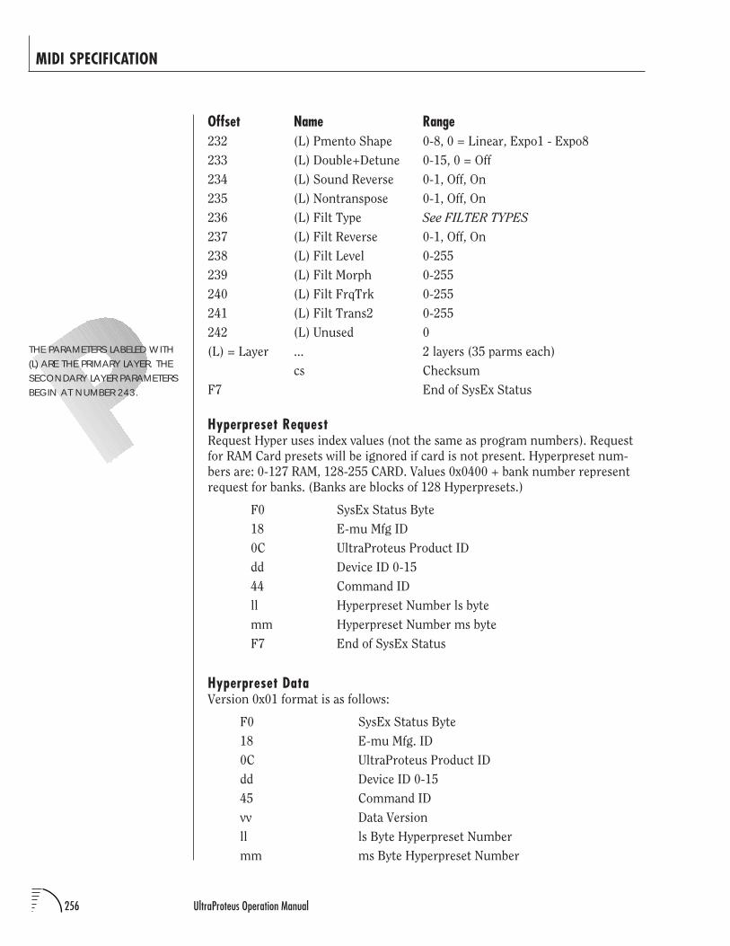
256 UltraProteus Operation Manual
MIDI SPECIFICATION
Offset Name Range232 (L) Pmento Shape 0-8, 0 = Linear, Expo1 - Expo8
233 (L) Double+Detune 0-15, 0 = Off
234 (L) Sound Reverse 0-1, Off, On
235 (L) Nontranspose 0-1, Off, On
236 (L) Filt Type See FILTER TYPES
237 (L) Filt Reverse 0-1, Off, On
238 (L) Filt Level 0-255
239 (L) Filt Morph 0-255
240 (L) Filt FrqTrk 0-255
241 (L) Filt Trans2 0-255
242 (L) Unused 0
(L) = Layer ... 2 layers (35 parms each)
cs Checksum
F7 End of SysEx Status
Hyperpreset RequestRequest Hyper uses index values (not the same as program numbers). Request
for RAM Card presets will be ignored if card is not present. Hyperpreset num-
bers are: 0-127 RAM, 128-255 CARD. Values 0x0400 + bank number represent
request for banks. (Banks are blocks of 128 Hyperpresets.)
F0 SysEx Status Byte
18 E-mu Mfg ID
0C UltraProteus Product ID
dd Device ID 0-15
44 Command ID
ll Hyperpreset Number ls byte
mm Hyperpreset Number ms byte
F7 End of SysEx Status
Hyperpreset DataVersion 0x01 format is as follows:
F0 SysEx Status Byte
18 E-mu Mfg. ID
0C UltraProteus Product ID
dd Device ID 0-15
45 Command ID
vv Data Version
ll ls Byte Hyperpreset Number
mm ms Byte Hyperpreset Number
THE PARAMETERS LABELED WITH(L) ARE THE PRIMARY LAYER. THESECONDARY LAYER PARAMETERSBEGIN AT NUMBER 243.
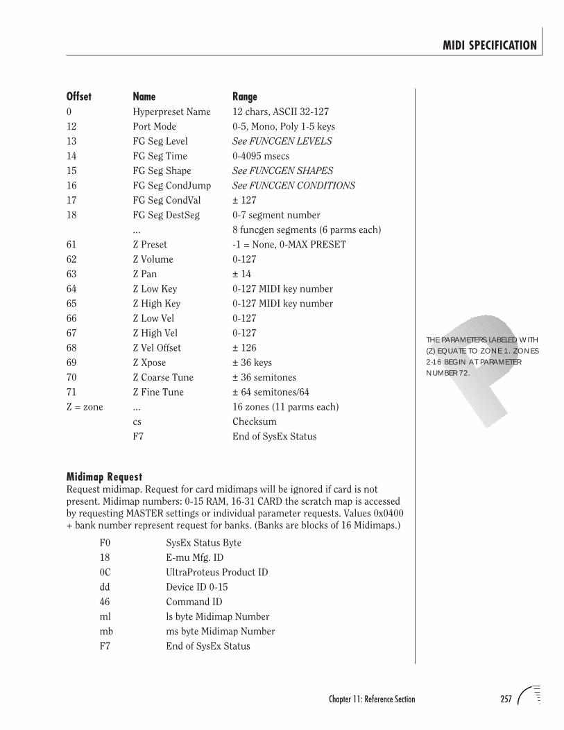
257Chapter 11: Reference Section
MIDI SPECIFICATION
Offset Name Range0 Hyperpreset Name 12 chars, ASCII 32-127
12 Port Mode 0-5, Mono, Poly 1-5 keys
13 FG Seg Level See FUNCGEN LEVELS
14 FG Seg Time 0-4095 msecs
15 FG Seg Shape See FUNCGEN SHAPES
16 FG Seg CondJump See FUNCGEN CONDITIONS
17 FG Seg CondVal ± 127
18 FG Seg DestSeg 0-7 segment number
... 8 funcgen segments (6 parms each)
61 Z Preset -1 = None, 0-MAX PRESET
62 Z Volume 0-127
63 Z Pan ± 14
64 Z Low Key 0-127 MIDI key number
65 Z High Key 0-127 MIDI key number
66 Z Low Vel 0-127
67 Z High Vel 0-127
68 Z Vel Offset ± 126
69 Z Xpose ± 36 keys
70 Z Coarse Tune ± 36 semitones
71 Z Fine Tune ± 64 semitones/64
Z = zone ... 16 zones (11 parms each)
cs Checksum
F7 End of SysEx Status
Midimap RequestRequest midimap. Request for card midimaps will be ignored if card is not
present. Midimap numbers: 0-15 RAM, 16-31 CARD the scratch map is accessed
by requesting MASTER settings or individual parameter requests. Values 0x0400
+ bank number represent request for banks. (Banks are blocks of 16 Midimaps.)
F0 SysEx Status Byte
18 E-mu Mfg. ID
0C UltraProteus Product ID
dd Device ID 0-15
46 Command ID
ml ls byte Midimap Number
mb ms byte Midimap Number
F7 End of SysEx Status
THE PARAMETERS LABELED WITH(Z) EQUATE TO ZONE 1. ZONES2-16 BEGIN AT PARAMETERNUMBER 72.
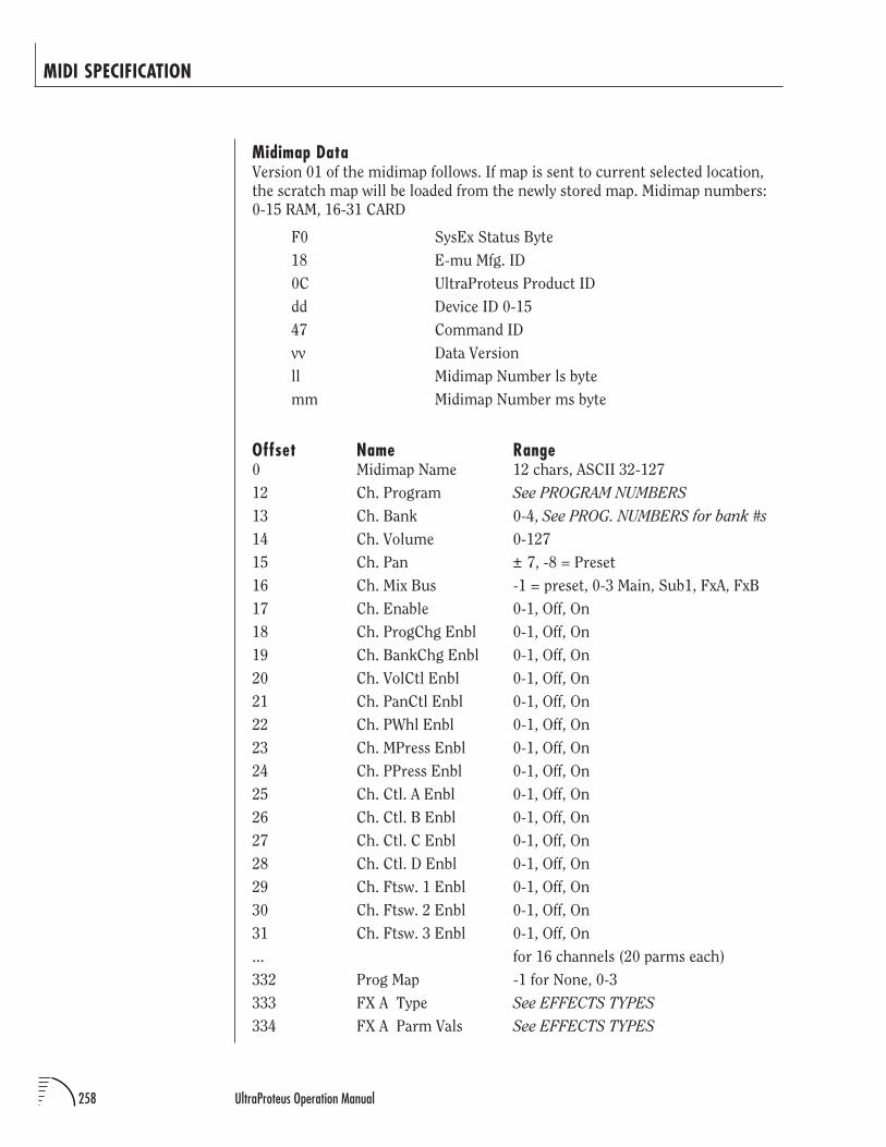
258 UltraProteus Operation Manual
MIDI SPECIFICATION
Midimap DataVersion 01 of the midimap follows. If map is sent to current selected location,
the scratch map will be loaded from the newly stored map. Midimap numbers:
0-15 RAM, 16-31 CARD
F0 SysEx Status Byte
18 E-mu Mfg. ID
0C UltraProteus Product ID
dd Device ID 0-15
47 Command ID
vv Data Version
ll Midimap Number ls byte
mm Midimap Number ms byte
Offset Name Range0 Midimap Name 12 chars, ASCII 32-127
12 Ch. Program See PROGRAM NUMBERS
13 Ch. Bank 0-4, See PROG. NUMBERS for bank #s
14 Ch. Volume 0-127
15 Ch. Pan ± 7, -8 = Preset
16 Ch. Mix Bus -1 = preset, 0-3 Main, Sub1, FxA, FxB
17 Ch. Enable 0-1, Off, On
18 Ch. ProgChg Enbl 0-1, Off, On
19 Ch. BankChg Enbl 0-1, Off, On
20 Ch. VolCtl Enbl 0-1, Off, On
21 Ch. PanCtl Enbl 0-1, Off, On
22 Ch. PWhl Enbl 0-1, Off, On
23 Ch. MPress Enbl 0-1, Off, On
24 Ch. PPress Enbl 0-1, Off, On
25 Ch. Ctl. A Enbl 0-1, Off, On
26 Ch. Ctl. B Enbl 0-1, Off, On
27 Ch. Ctl. C Enbl 0-1, Off, On
28 Ch. Ctl. D Enbl 0-1, Off, On
29 Ch. Ftsw. 1 Enbl 0-1, Off, On
30 Ch. Ftsw. 2 Enbl 0-1, Off, On
31 Ch. Ftsw. 3 Enbl 0-1, Off, On
... for 16 channels (20 parms each)
332 Prog Map -1 for None, 0-3
333 FX A Type See EFFECTS TYPES
334 FX A Parm Vals See EFFECTS TYPES
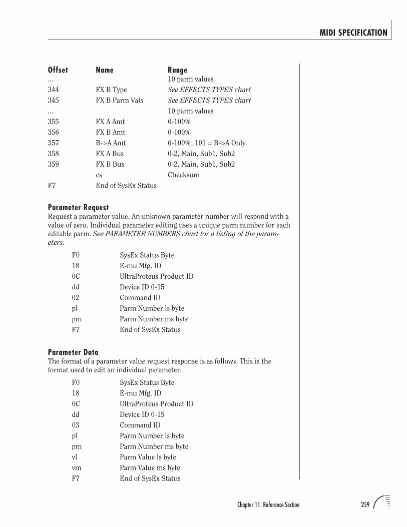
259Chapter 11: Reference Section
MIDI SPECIFICATION
Offset Name Range... 10 parm values
344 FX B Type See EFFECTS TYPES chart
345 FX B Parm Vals See EFFECTS TYPES chart
... 10 parm values
355 FX A Amt 0-100%
356 FX B Amt 0-100%
357 B->A Amt 0-100%, 101 = B->A Only
358 FX A Bus 0-2, Main, Sub1, Sub2
359 FX B Bus 0-2, Main, Sub1, Sub2
cs Checksum
F7 End of SysEx Status
Parameter RequestRequest a parameter value. An unknown parameter number will respond with a
value of zero. Individual parameter editing uses a unique parm number for each
editable parm. See PARAMETER NUMBERS chart for a listing of the param-
eters.
F0 SysEx Status Byte
18 E-mu Mfg. ID
0C UltraProteus Product ID
dd Device ID 0-15
02 Command ID
pl Parm Number ls byte
pm Parm Number ms byte
F7 End of SysEx Status
Parameter DataThe format of a parameter value request response is as follows. This is the
format used to edit an individual parameter.
F0 SysEx Status Byte
18 E-mu Mfg. ID
0C UltraProteus Product ID
dd Device ID 0-15
03 Command ID
pl Parm Number ls byte
pm Parm Number ms byte
vl Parm Value ls byte
vm Parm Value ms byte
F7 End of SysEx Status
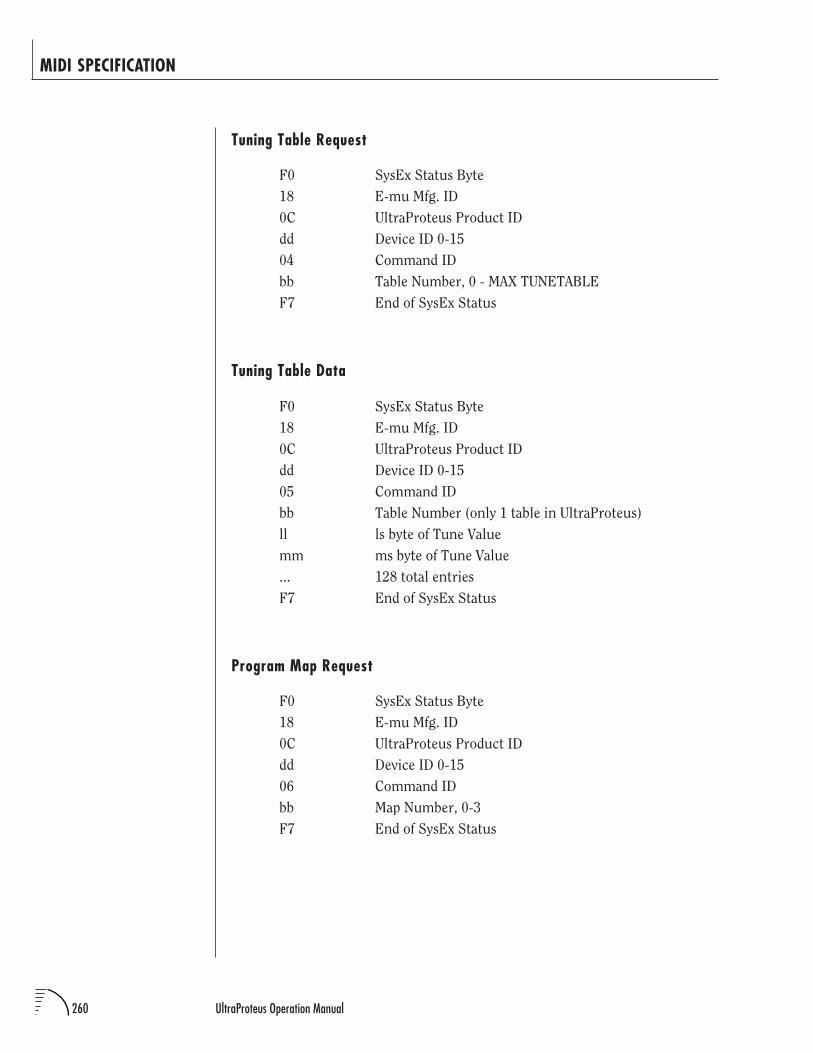
260 UltraProteus Operation Manual
MIDI SPECIFICATION
Tuning Table Request
F0 SysEx Status Byte
18 E-mu Mfg. ID
0C UltraProteus Product ID
dd Device ID 0-15
04 Command ID
bb Table Number, 0 - MAX TUNETABLE
F7 End of SysEx Status
Tuning Table Data
F0 SysEx Status Byte
18 E-mu Mfg. ID
0C UltraProteus Product ID
dd Device ID 0-15
05 Command ID
bb Table Number (only 1 table in UltraProteus)
ll ls byte of Tune Value
mm ms byte of Tune Value
... 128 total entries
F7 End of SysEx Status
Program Map Request
F0 SysEx Status Byte
18 E-mu Mfg. ID
0C UltraProteus Product ID
dd Device ID 0-15
06 Command ID
bb Map Number, 0-3
F7 End of SysEx Status
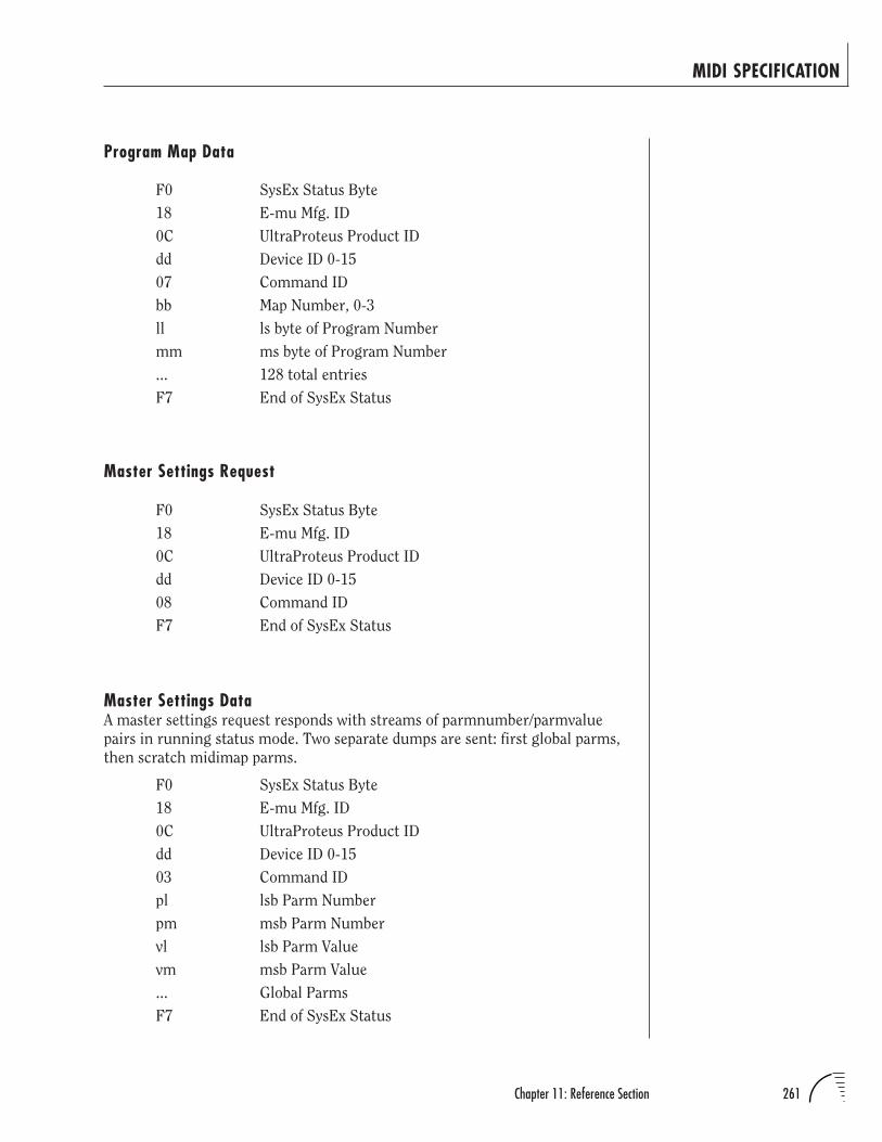
261Chapter 11: Reference Section
Program Map Data
F0 SysEx Status Byte
18 E-mu Mfg. ID
0C UltraProteus Product ID
dd Device ID 0-15
07 Command ID
bb Map Number, 0-3
ll ls byte of Program Number
mm ms byte of Program Number
... 128 total entries
F7 End of SysEx Status
Master Settings Request
F0 SysEx Status Byte
18 E-mu Mfg. ID
0C UltraProteus Product ID
dd Device ID 0-15
08 Command ID
F7 End of SysEx Status
Master Settings DataA master settings request responds with streams of parmnumber/parmvalue
pairs in running status mode. Two separate dumps are sent: first global parms,
then scratch midimap parms.
F0 SysEx Status Byte
18 E-mu Mfg. ID
0C UltraProteus Product ID
dd Device ID 0-15
03 Command ID
pl lsb Parm Number
pm msb Parm Number
vl lsb Parm Value
vm msb Parm Value
... Global Parms
F7 End of SysEx Status
MIDI SPECIFICATION
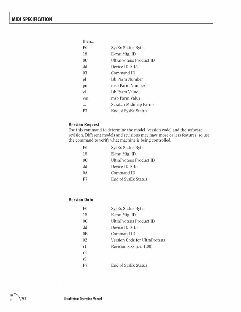
262 UltraProteus Operation Manual
then...
F0 SysEx Status Byte
18 E-mu Mfg. ID
0C UltraProteus Product ID
dd Device ID 0-15
03 Command ID
pl lsb Parm Number
pm msb Parm Number
vl lsb Parm Value
vm msb Parm Value
... Scratch Midimap Parms
F7 End of SysEx Status
Version RequestUse this command to determine the model (version code) and the software
revision. Different models and revisions may have more or less features, so use
the command to verify what machine is being controlled.
F0 SysEx Status Byte
18 E-mu Mfg. ID
0C UltraProteus Product ID
dd Device ID 0-15
0A Command ID
F7 End of SysEx Status
Version Data
F0 SysEx Status Byte
18 E-mu Mfg. ID
0C UltraProteus Product ID
dd Device ID 0-15
0B Command ID
02 Version Code for UltraProteus
r1 Revision x.xx (i.e. 1.00)
r2
r2
F7 End of SysEx Status
MIDI SPECIFICATION
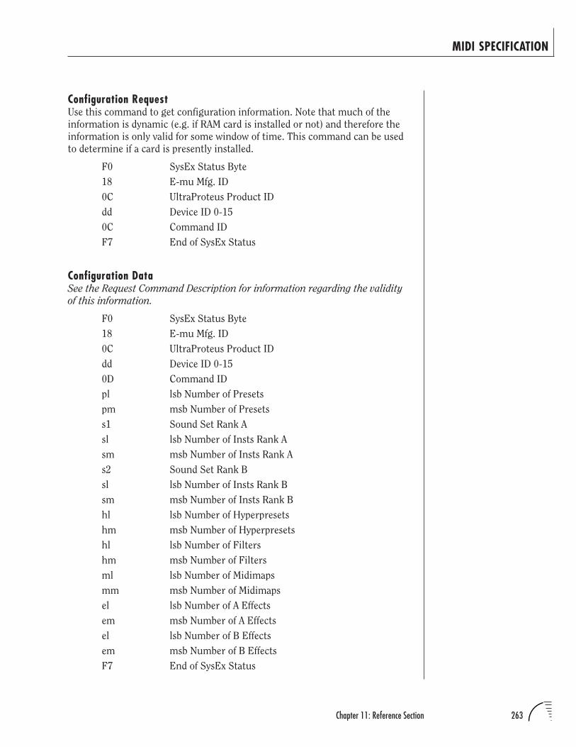
263Chapter 11: Reference Section
Configuration RequestUse this command to get configuration information. Note that much of the
information is dynamic (e.g. if RAM card is installed or not) and therefore the
information is only valid for some window of time. This command can be used
to determine if a card is presently installed.
F0 SysEx Status Byte
18 E-mu Mfg. ID
0C UltraProteus Product ID
dd Device ID 0-15
0C Command ID
F7 End of SysEx Status
Configuration DataSee the Request Command Description for information regarding the validity
of this information.
F0 SysEx Status Byte
18 E-mu Mfg. ID
0C UltraProteus Product ID
dd Device ID 0-15
0D Command ID
pl lsb Number of Presets
pm msb Number of Presets
s1 Sound Set Rank A
sl lsb Number of Insts Rank A
sm msb Number of Insts Rank A
s2 Sound Set Rank B
sl lsb Number of Insts Rank B
sm msb Number of Insts Rank B
hl lsb Number of Hyperpresets
hm msb Number of Hyperpresets
hl lsb Number of Filters
hm msb Number of Filters
ml lsb Number of Midimaps
mm msb Number of Midimaps
el lsb Number of A Effects
em msb Number of A Effects
el lsb Number of B Effects
em msb Number of B Effects
F7 End of SysEx Status
MIDI SPECIFICATION
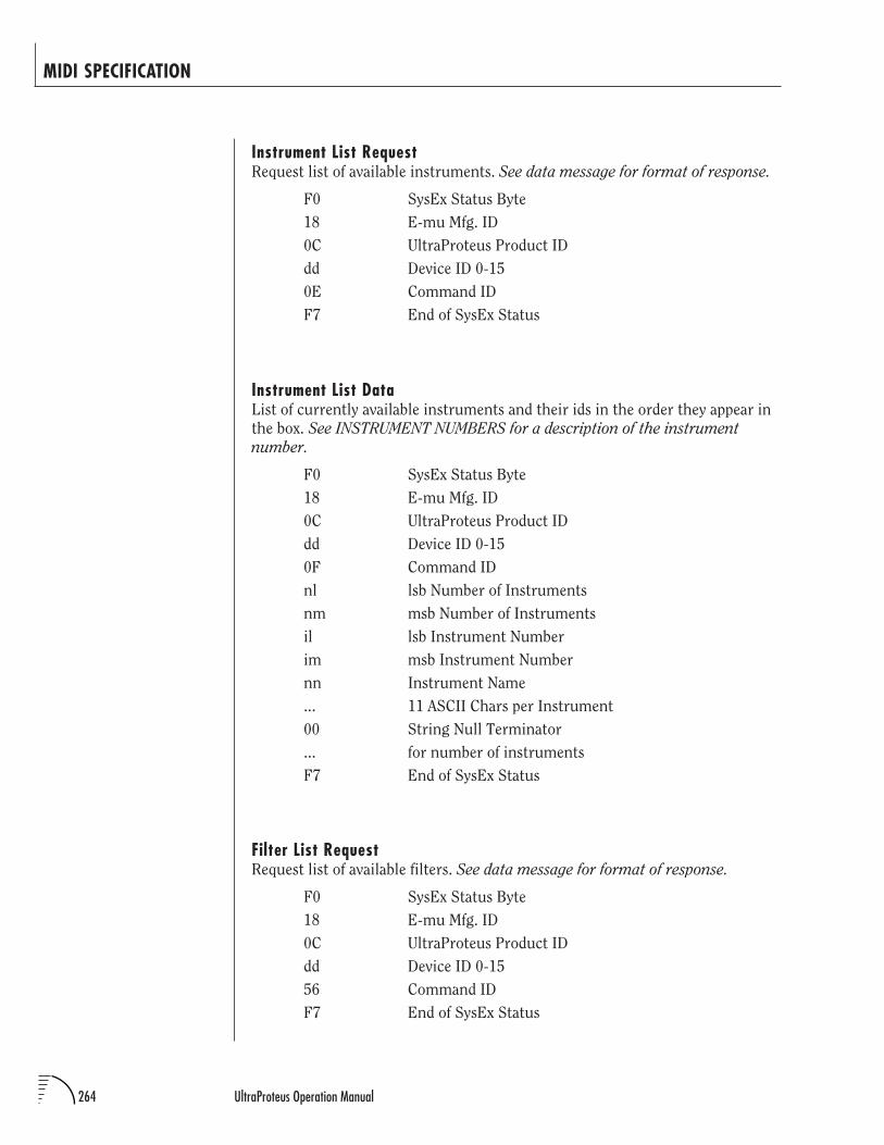
264 UltraProteus Operation Manual
Instrument List RequestRequest list of available instruments. See data message for format of response.
F0 SysEx Status Byte
18 E-mu Mfg. ID
0C UltraProteus Product ID
dd Device ID 0-15
0E Command ID
F7 End of SysEx Status
Instrument List DataList of currently available instruments and their ids in the order they appear in
the box. See INSTRUMENT NUMBERS for a description of the instrument
number.
F0 SysEx Status Byte
18 E-mu Mfg. ID
0C UltraProteus Product ID
dd Device ID 0-15
0F Command ID
nl lsb Number of Instruments
nm msb Number of Instruments
il lsb Instrument Number
im msb Instrument Number
nn Instrument Name
... 11 ASCII Chars per Instrument
00 String Null Terminator
... for number of instruments
F7 End of SysEx Status
Filter List RequestRequest list of available filters. See data message for format of response.
F0 SysEx Status Byte
18 E-mu Mfg. ID
0C UltraProteus Product ID
dd Device ID 0-15
56 Command ID
F7 End of SysEx Status
MIDI SPECIFICATION
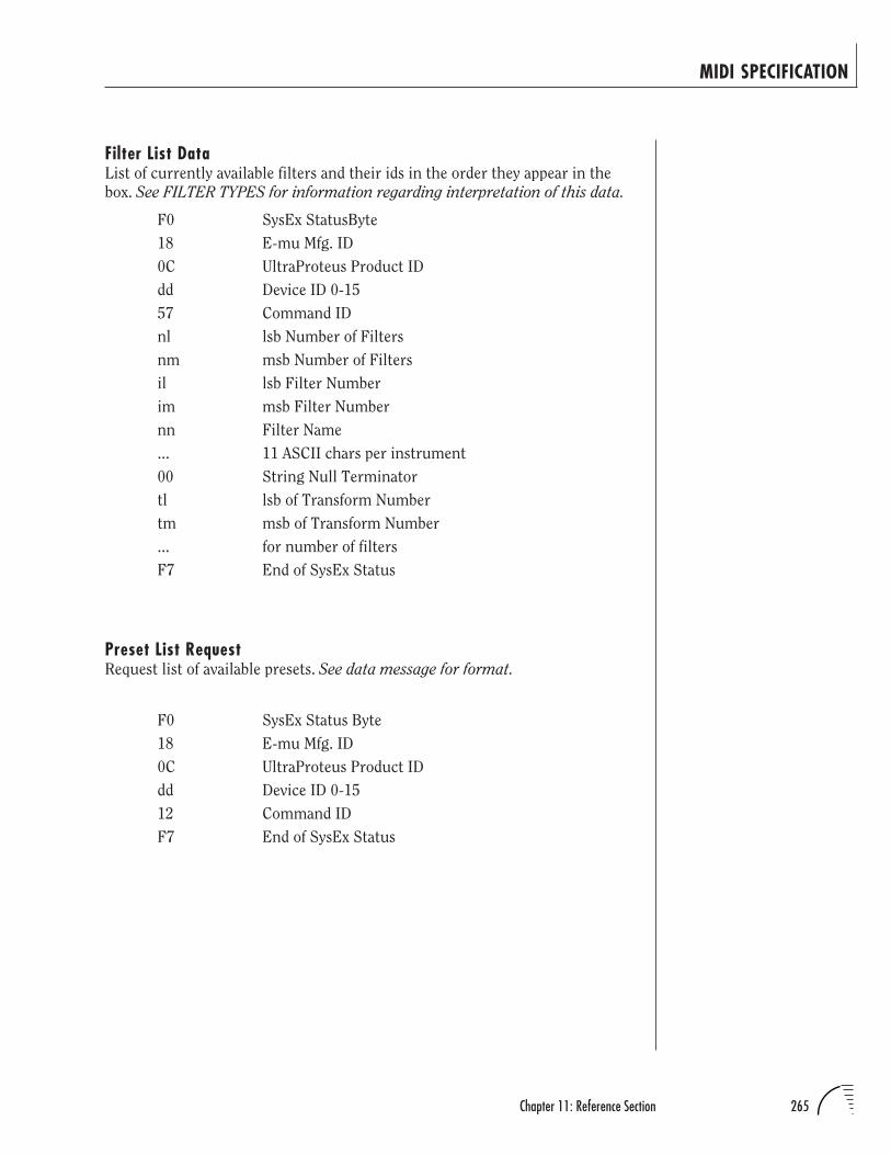
265Chapter 11: Reference Section
Filter List DataList of currently available filters and their ids in the order they appear in the
box. See FILTER TYPES for information regarding interpretation of this data.
F0 SysEx StatusByte
18 E-mu Mfg. ID
0C UltraProteus Product ID
dd Device ID 0-15
57 Command ID
nl lsb Number of Filters
nm msb Number of Filters
il lsb Filter Number
im msb Filter Number
nn Filter Name
... 11 ASCII chars per instrument
00 String Null Terminator
tl lsb of Transform Number
tm msb of Transform Number
... for number of filters
F7 End of SysEx Status
Preset List RequestRequest list of available presets. See data message for format.
F0 SysEx Status Byte
18 E-mu Mfg. ID
0C UltraProteus Product ID
dd Device ID 0-15
12 Command ID
F7 End of SysEx Status
MIDI SPECIFICATION
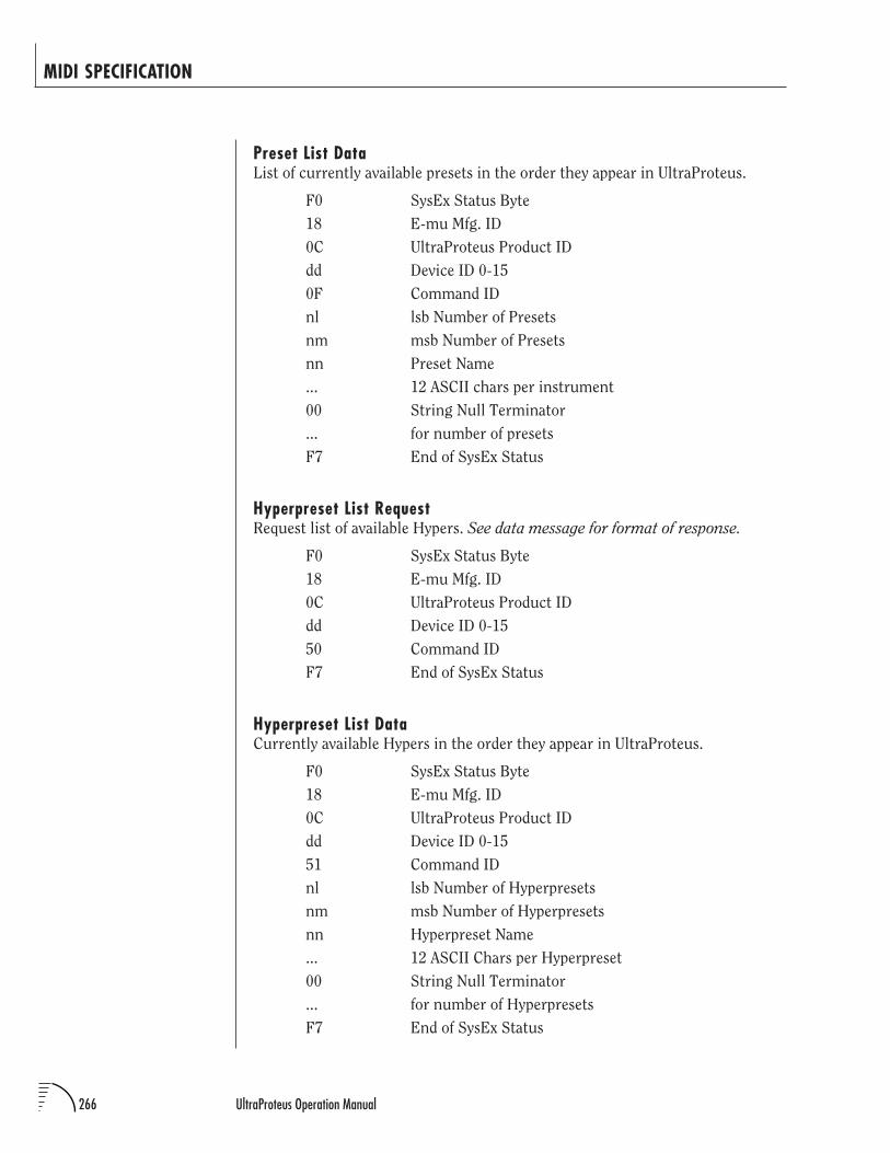
266 UltraProteus Operation Manual
Preset List DataList of currently available presets in the order they appear in UltraProteus.
F0 SysEx Status Byte
18 E-mu Mfg. ID
0C UltraProteus Product ID
dd Device ID 0-15
0F Command ID
nl lsb Number of Presets
nm msb Number of Presets
nn Preset Name
... 12 ASCII chars per instrument
00 String Null Terminator
... for number of presets
F7 End of SysEx Status
Hyperpreset List RequestRequest list of available Hypers. See data message for format of response.
F0 SysEx Status Byte
18 E-mu Mfg. ID
0C UltraProteus Product ID
dd Device ID 0-15
50 Command ID
F7 End of SysEx Status
Hyperpreset List DataCurrently available Hypers in the order they appear in UltraProteus.
F0 SysEx Status Byte
18 E-mu Mfg. ID
0C UltraProteus Product ID
dd Device ID 0-15
51 Command ID
nl lsb Number of Hyperpresets
nm msb Number of Hyperpresets
nn Hyperpreset Name
... 12 ASCII Chars per Hyperpreset
00 String Null Terminator
... for number of Hyperpresets
F7 End of SysEx Status
MIDI SPECIFICATION
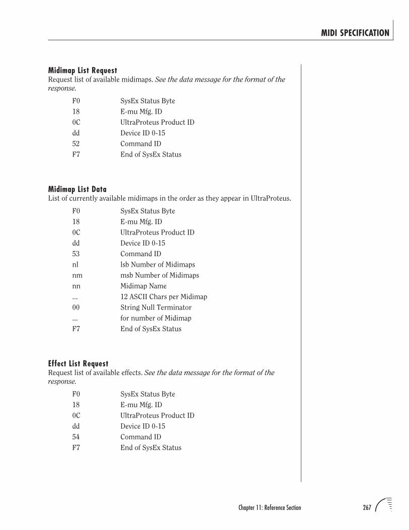
267Chapter 11: Reference Section
Midimap List RequestRequest list of available midimaps. See the data message for the format of the
response.
F0 SysEx Status Byte
18 E-mu Mfg. ID
0C UltraProteus Product ID
dd Device ID 0-15
52 Command ID
F7 End of SysEx Status
Midimap List DataList of currently available midimaps in the order as they appear in UltraProteus.
F0 SysEx Status Byte
18 E-mu Mfg. ID
0C UltraProteus Product ID
dd Device ID 0-15
53 Command ID
nl lsb Number of Midimaps
nm msb Number of Midimaps
nn Midimap Name
... 12 ASCII Chars per Midimap
00 String Null Terminator
... for number of Midimap
F7 End of SysEx Status
Effect List RequestRequest list of available effects. See the data message for the format of the
response.
F0 SysEx Status Byte
18 E-mu Mfg. ID
0C UltraProteus Product ID
dd Device ID 0-15
54 Command ID
F7 End of SysEx Status
MIDI SPECIFICATION
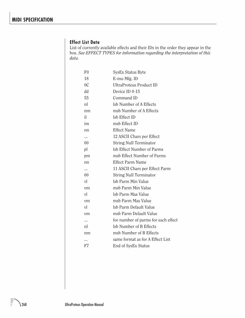
268 UltraProteus Operation Manual
Effect List DataList of currently available effects and their IDs in the order they appear in the
box. See EFFECT TYPES for information regarding the interpretation of this
data.
F0 SysEx Status Byte
18 E-mu Mfg. ID
0C UltraProteus Product ID
dd Device ID 0-15
55 Command ID
nl lsb Number of A Effects
nm msb Number of A Effects
il lsb Effect ID
im msb Effect ID
nn Effect Name
... 12 ASCII Chars per Effect
00 String Null Terminator
pl lsb Effect Number of Parms
pm msb Effect Number of Parms
nn Effect Parm Name
... 11 ASCII Chars per Effect Parm
00 String Null Terminator
vl lsb Parm Min Value
vm msb Parm Min Value
vl lsb Parm Max Value
vm msb Parm Max Value
vl lsb Parm Default Value
vm msb Parm Default Value
... for number of parms for each effect
nl lsb Number of B Effects
nm msb Number of B Effects
... same format as for A Effect List
F7 End of SysEx Status
MIDI SPECIFICATION
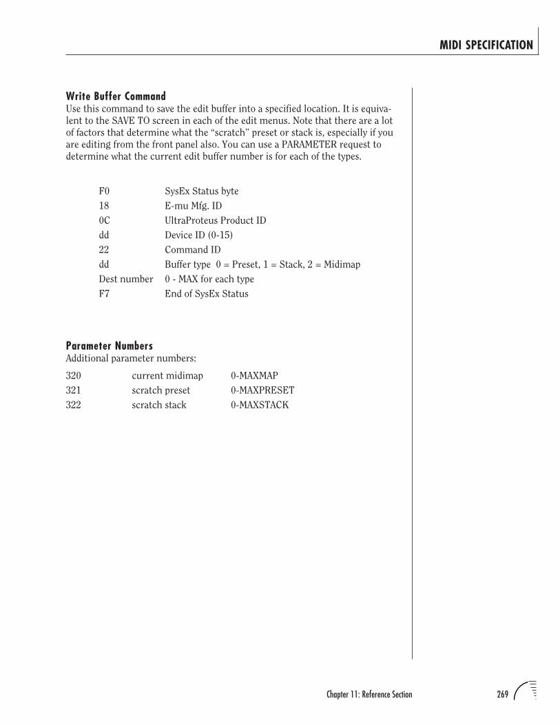
269Chapter 11: Reference Section
Write Buffer CommandUse this command to save the edit buffer into a specified location. It is equiva-
lent to the SAVE TO screen in each of the edit menus. Note that there are a lot
of factors that determine what the “scratch” preset or stack is, especially if you
are editing from the front panel also. You can use a PARAMETER request to
determine what the current edit buffer number is for each of the types.
F0 SysEx Status byte
18 E-mu Mfg. ID
0C UltraProteus Product ID
dd Device ID (0-15)
22 Command ID
dd Buffer type 0 = Preset, 1 = Stack, 2 = Midimap
Dest number 0 - MAX for each type
F7 End of SysEx Status
Parameter NumbersAdditional parameter numbers:
320 current midimap 0-MAXMAP
321 scratch preset 0-MAXPRESET
322 scratch stack 0-MAXSTACK
MIDI SPECIFICATION
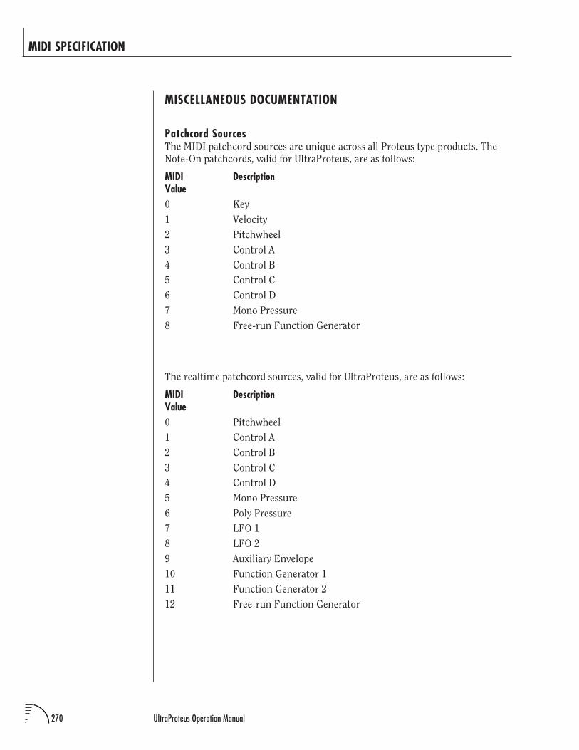
270 UltraProteus Operation Manual
MIDI SPECIFICATION
MISCELLANEOUS DOCUMENTATION
Patchcord SourcesThe MIDI patchcord sources are unique across all Proteus type products. The
Note-On patchcords, valid for UltraProteus, are as follows:
MIDI DescriptionValue0 Key
1 Velocity
2 Pitchwheel
3 Control A
4 Control B
5 Control C
6 Control D
7 Mono Pressure
8 Free-run Function Generator
The realtime patchcord sources, valid for UltraProteus, are as follows:
MIDI DescriptionValue0 Pitchwheel
1 Control A
2 Control B
3 Control C
4 Control D
5 Mono Pressure
6 Poly Pressure
7 LFO 1
8 LFO 2
9 Auxiliary Envelope
10 Function Generator 1
11 Function Generator 2
12 Free-run Function Generator
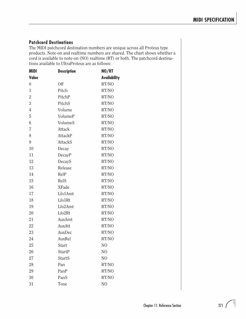
271Chapter 11: Reference Section
MIDI SPECIFICATION
Patchcord DestinationsThe MIDI patchcord destination numbers are unique across all Proteus type
products. Note-on and realtime numbers are shared. The chart shows whether a
cord is available to note-on (NO) realtime (RT) or both. The patchcord destina-
tions available to UltraProteus are as follows:
MIDI Description NO/RTValue Availability0 Off RT/NO
1 Pitch RT/NO
2 PitchP RT/NO
3 PitchS RT/NO
4 Volume RT/NO
5 VolumeP RT/NO
6 VolumeS RT/NO
7 Attack RT/NO
8 AttackP RT/NO
9 AttackS RT/NO
10 Decay RT/NO
11 DecayP RT/NO
12 DecayS RT/NO
13 Release RT/NO
14 RelP RT/NO
15 RelS RT/NO
16 XFade RT/NO
17 Lfo1Amt RT/NO
18 Lfo1Rt RT/NO
19 Lfo2Amt RT/NO
20 Lfo2Rt RT/NO
21 AuxAmt RT/NO
22 AuxAtt RT/NO
23 AuxDec RT/NO
24 AuxRel RT/NO
25 Start NO
26 StartP NO
27 StartS NO
28 Pan RT/NO
29 PanP RT/NO
30 PanS RT/NO
31 Tone NO
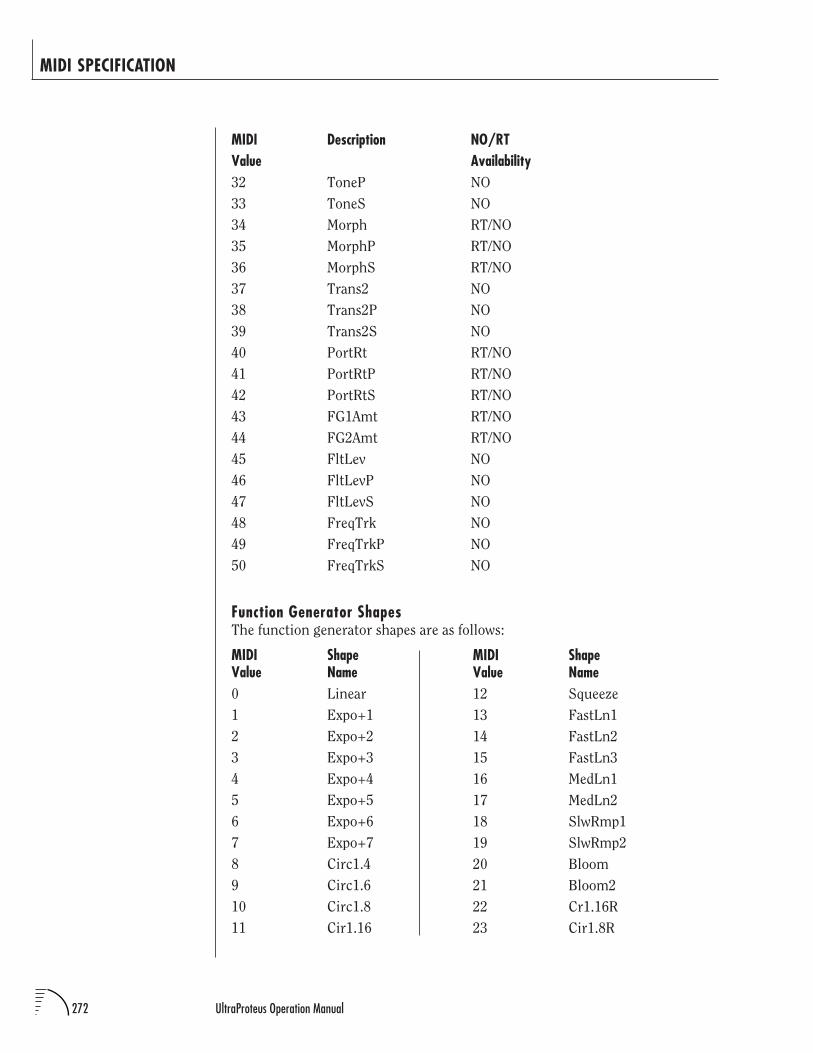
272 UltraProteus Operation Manual
MIDI SPECIFICATION
MIDI Description NO/RTValue Availability32 ToneP NO
33 ToneS NO
34 Morph RT/NO
35 MorphP RT/NO
36 MorphS RT/NO
37 Trans2 NO
38 Trans2P NO
39 Trans2S NO
40 PortRt RT/NO
41 PortRtP RT/NO
42 PortRtS RT/NO
43 FG1Amt RT/NO
44 FG2Amt RT/NO
45 FltLev NO
46 FltLevP NO
47 FltLevS NO
48 FreqTrk NO
49 FreqTrkP NO
50 FreqTrkS NO
Function Generator ShapesThe function generator shapes are as follows:
MIDI ShapeValue Name0 Linear
1 Expo+1
2 Expo+2
3 Expo+3
4 Expo+4
5 Expo+5
6 Expo+6
7 Expo+7
8 Circ1.4
9 Circ1.6
10 Circ1.8
11 Cir1.16
MIDI ShapeValue Name12 Squeeze
13 FastLn1
14 FastLn2
15 FastLn3
16 MedLn1
17 MedLn2
18 SlwRmp1
19 SlwRmp2
20 Bloom
21 Bloom2
22 Cr1.16R
23 Cir1.8R
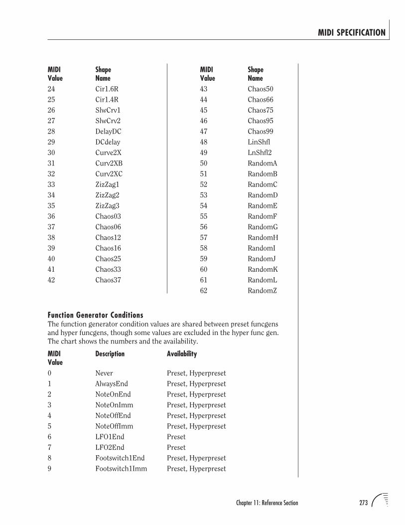
273Chapter 11: Reference Section
MIDI SPECIFICATION
MIDI ShapeValue Name43 Chaos50
44 Chaos66
45 Chaos75
46 Chaos95
47 Chaos99
48 LinShfl
49 LnShfl2
50 RandomA
51 RandomB
52 RandomC
53 RandomD
54 RandomE
55 RandomF
56 RandomG
57 RandomH
58 RandomI
59 RandomJ
60 RandomK
61 RandomL
62 RandomZ
MIDI ShapeValue Name24 Cir1.6R
25 Cir1.4R
26 SlwCrv1
27 SlwCrv2
28 DelayDC
29 DCdelay
30 Curve2X
31 Curv2XB
32 Curv2XC
33 ZizZag1
34 ZizZag2
35 ZizZag3
36 Chaos03
37 Chaos06
38 Chaos12
39 Chaos16
40 Chaos25
41 Chaos33
42 Chaos37
Function Generator ConditionsThe function generator condition values are shared between preset funcgens
and hyper funcgens, though some values are excluded in the hyper func gen.
The chart shows the numbers and the availability.
MIDI Description AvailabilityValue0 Never Preset, Hyperpreset
1 AlwaysEnd Preset, Hyperpreset
2 NoteOnEnd Preset, Hyperpreset
3 NoteOnImm Preset, Hyperpreset
4 NoteOffEnd Preset, Hyperpreset
5 NoteOffImm Preset, Hyperpreset
6 LFO1End Preset
7 LFO2End Preset
8 Footswitch1End Preset, Hyperpreset
9 Footswitch1Imm Preset, Hyperpreset
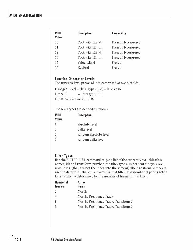
274 UltraProteus Operation Manual
MIDI SPECIFICATION
MIDI Description AvailabilityValue10 Footswitch2End Preset, Hyperpreset
11 Footswitch2Imm Preset, Hyperpreset
12 Footswitch3End Preset, Hyperpreset
13 Footswitch3Imm Preset, Hyperpreset
14 VelocityEnd Preset
15 KeyEnd Preset
Function Generator LevelsThe funcgen level parm value is comprised of two bitfields.
Funcgen Level = (levelType << 8) + levelValue
bits 8-13 = level type, 0-3
bits 0-7 = level value, +-127
The level types are defined as follows:
MIDI DescriptionValue0 absolute level
1 delta level
2 random absolute level
3 random delta level
Filter TypesUse the FILTER LIST command to get a list of the currently available filter
names, ids and transform number. the filter type number sent via sysex are
unique ids. (they are not the index into the screens) The transform number is
used to determine the active parms for that filter. The number of parms active
for any filter is determined by the number of frames in the filter.
Number of ActiveFrames Parms2 Morph
4 Morph, Frequency Track
6 Morph, Frequency Track, Transform 2
8 Morph, Frequency Track, Transform 2
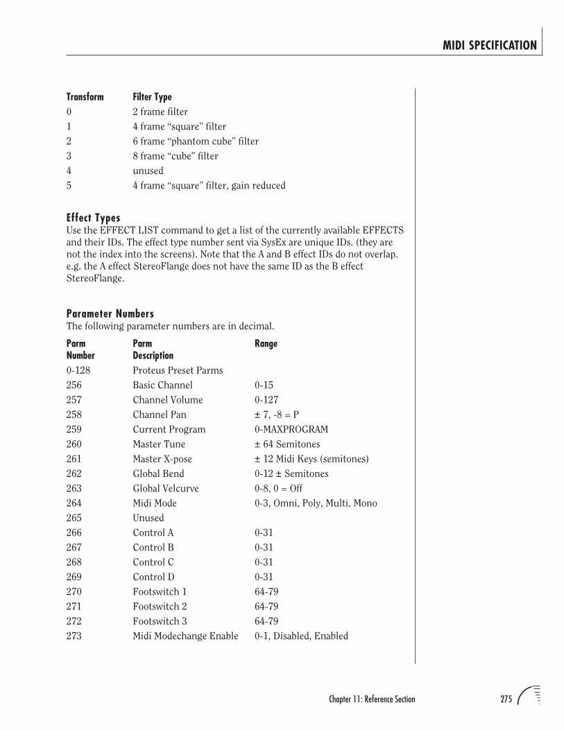
275Chapter 11: Reference Section
MIDI SPECIFICATION
Transform Filter Type0 2 frame filter
1 4 frame “square” filter
2 6 frame “phantom cube” filter
3 8 frame “cube” filter
4 unused
5 4 frame “square” filter, gain reduced
Effect TypesUse the EFFECT LIST command to get a list of the currently available EFFECTS
and their IDs. The effect type number sent via SysEx are unique IDs. (they are
not the index into the screens). Note that the A and B effect IDs do not overlap.
e.g. the A effect StereoFlange does not have the same ID as the B effect
StereoFlange.
Parameter NumbersThe following parameter numbers are in decimal.
Parm Parm RangeNumber Description0-128 Proteus Preset Parms
256 Basic Channel 0-15
257 Channel Volume 0-127
258 Channel Pan ± 7, -8 = P
259 Current Program 0-MAXPROGRAM
260 Master Tune ± 64 Semitones
261 Master X-pose ± 12 Midi Keys (semitones)
262 Global Bend 0-12 ± Semitones
263 Global Velcurve 0-8, 0 = Off
264 Midi Mode 0-3, Omni, Poly, Multi, Mono
265 Unused
266 Control A 0-31
267 Control B 0-31
268 Control C 0-31
269 Control D 0-31
270 Footswitch 1 64-79
271 Footswitch 2 64-79
272 Footswitch 3 64-79
273 Midi Modechange Enable 0-1, Disabled, Enabled
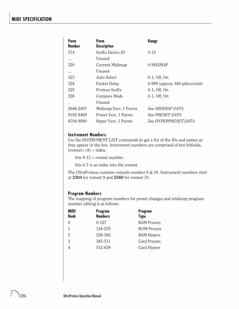
276 UltraProteus Operation Manual
MIDI SPECIFICATION
Parm Parm RangeNumber Description274 SysEx Device ID 0-15
... Unused
320 Current Midimap 0-MAXMAP
... Unused
323 Auto Select 0-1, Off, On
324 Packet Delay 0-999 (approx. 600 µSecs/unit)
325 Proteus SysEx 0-1, Off, On
326 Compare Mode 0-1, Off, On
.. Unused
2048-2407 Midimap Vers. 1 Parms See MIDIMAP DATA
8192-8469 Preset Vers. 1 Parms See PRESET DATA
8704-8940 Hyper Vers. 1 Parms See HYPERPRESET DATA
Instrument NumbersUse the INSTRUMENT LIST commands to get a list of the IDs and names as
they appear in the box. Instrument numbers are comprised of two bitfields.
(romset<<8) + index.
bits 8-13 = romset number.
bits 0-7 is an index into the romset.
The UltraProteus contains romsets number 9 & 10. Instrument numbers start
at 2304 for romset 9 and 2560 for romset 10.
Program NumbersThe mapping of program numbers for preset changes and midimap program
number editing is as follows:
MIDI Program ProgramBank Numbers Type0 0-127 RAM Presets
1 128-255 ROM Presets
2 256-383 RAM Hypers
3 383-511 Card Presets
4 512-639 Card Hypers
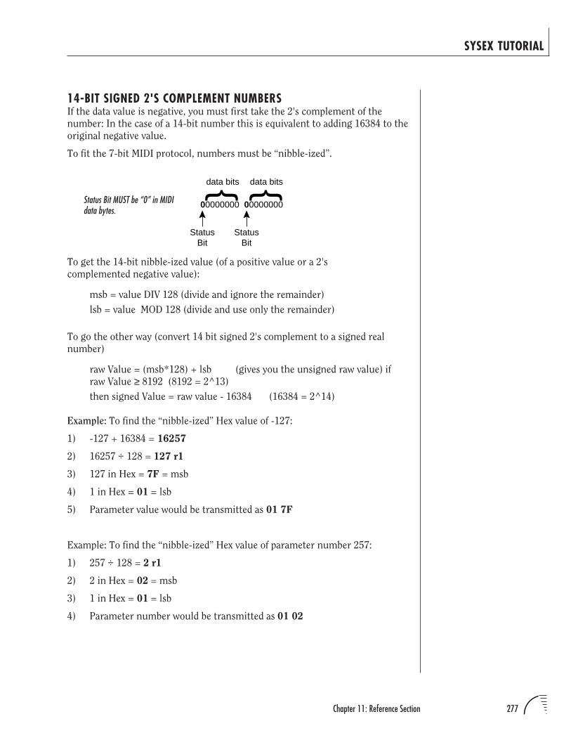
277Chapter 11: Reference Section
SYSEX TUTORIAL
14-BIT SIGNED 2'S COMPLEMENT NUMBERSIf the data value is negative, you must first take the 2's complement of the
number: In the case of a 14-bit number this is equivalent to adding 16384 to the
original negative value.
To fit the 7-bit MIDI protocol, numbers must be “nibble-ized”.
To get the 14-bit nibble-ized value (of a positive value or a 2's
complemented negative value):
msb = value DIV 128 (divide and ignore the remainder)
lsb = value MOD 128 (divide and use only the remainder)
To go the other way (convert 14 bit signed 2's complement to a signed real
number)
raw Value = (msb*128) + lsb (gives you the unsigned raw value) if
raw Value ≥ 8192 (8192 = 2^13)
then signed Value = raw value - 16384 (16384 = 2^14)
Example: To find the “nibble-ized” Hex value of -127:
1) -127 + 16384 = 16257
2) 16257 ÷ 128 = 127 r1
3) 127 in Hex = 7F = msb
4) 1 in Hex = 01 = lsb
5) Parameter value would be transmitted as 01 7F
Example: To find the “nibble-ized” Hex value of parameter number 257:
1) 257 ÷ 128 = 2 r1
2) 2 in Hex = 02 = msb
3) 1 in Hex = 01 = lsb
4) Parameter number would be transmitted as 01 02
00000000 00000000
data bits data bits
StatusBit
StatusBit
Status Bit MUST be “0” in MIDIdata bytes.
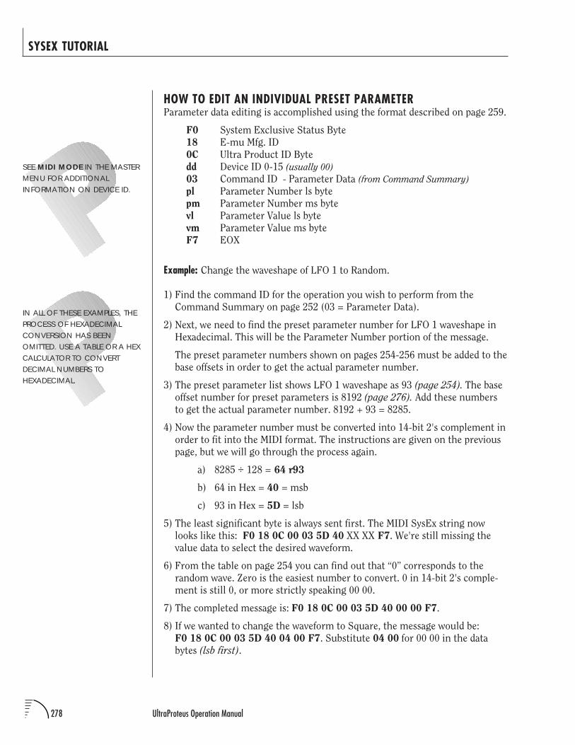
278 UltraProteus Operation Manual
SYSEX TUTORIAL
HOW TO EDIT AN INDIVIDUAL PRESET PARAMETERParameter data editing is accomplished using the format described on page 259.
F0 System Exclusive Status Byte
18 E-mu Mfg. ID
0C Ultra Product ID Byte
dd Device ID 0-15 (usually 00)
03 Command ID - Parameter Data (from Command Summary)
pl Parameter Number ls byte
pm Parameter Number ms byte
vl Parameter Value ls byte
vm Parameter Value ms byte
F7 EOX
Example: Change the waveshape of LFO 1 to Random.
1) Find the command ID for the operation you wish to perform from the
Command Summary on page 252 (03 = Parameter Data).
2) Next, we need to find the preset parameter number for LFO 1 waveshape in
Hexadecimal. This will be the Parameter Number portion of the message.
The preset parameter numbers shown on pages 254-256 must be added to the
base offsets in order to get the actual parameter number.
3) The preset parameter list shows LFO 1 waveshape as 93 (page 254). The base
offset number for preset parameters is 8192 (page 276). Add these numbers
to get the actual parameter number. 8192 + 93 = 8285.
4) Now the parameter number must be converted into 14-bit 2's complement in
order to fit into the MIDI format. The instructions are given on the previous
page, but we will go through the process again.
a) 8285 ÷ 128 = 64 r93
b) 64 in Hex = 40 = msb
c) 93 in Hex = 5D = lsb
5) The least significant byte is always sent first. The MIDI SysEx string now
looks like this: F0 18 0C 00 03 5D 40 XX XX F7. We're still missing the
value data to select the desired waveform.
6) From the table on page 254 you can find out that “0” corresponds to the
random wave. Zero is the easiest number to convert. 0 in 14-bit 2's comple-
ment is still 0, or more strictly speaking 00 00.
7) The completed message is: F0 18 0C 00 03 5D 40 00 00 F7.
8) If we wanted to change the waveform to Square, the message would be:
F0 18 0C 00 03 5D 40 04 00 F7. Substitute 04 00 for 00 00 in the data
bytes (lsb first).
IN ALL OF THESE EXAMPLES, THEPROCESS OF HEXADECIMALCONVERSION HAS BEENOMITTED. USE A TABLE OR A HEXCALCULATOR TO CONVERTDECIMAL NUMBERS TOHEXADECIMAL.
SEE MIDI MODE IN THE MASTERMENU FOR ADDITIONALINFORMATION ON DEVICE ID.
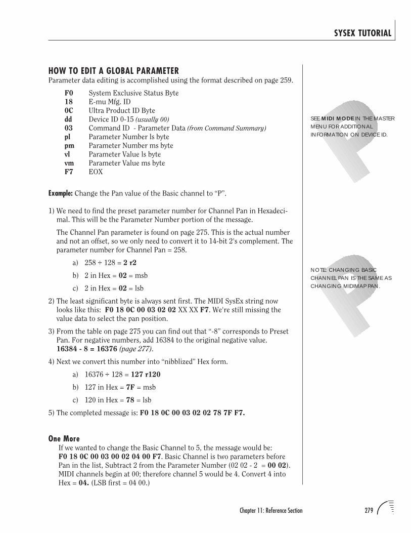
279Chapter 11: Reference Section
SYSEX TUTORIAL
HOW TO EDIT A GLOBAL PARAMETERParameter data editing is accomplished using the format described on page 259.
F0 System Exclusive Status Byte
18 E-mu Mfg. ID
0C Ultra Product ID Byte
dd Device ID 0-15 (usually 00)
03 Command ID - Parameter Data (from Command Summary)
pl Parameter Number ls byte
pm Parameter Number ms byte
vl Parameter Value ls byte
vm Parameter Value ms byte
F7 EOX
Example: Change the Pan value of the Basic channel to “P”.
1) We need to find the preset parameter number for Channel Pan in Hexadeci-
mal. This will be the Parameter Number portion of the message.
The Channel Pan parameter is found on page 275. This is the actual number
and not an offset, so we only need to convert it to 14-bit 2's complement. The
parameter number for Channel Pan = 258.
a) 258 ÷ 128 = 2 r2
b) 2 in Hex = 02 = msb
c) 2 in Hex = 02 = lsb
2) The least significant byte is always sent first. The MIDI SysEx string now
looks like this: F0 18 0C 00 03 02 02 XX XX F7. We're still missing the
value data to select the pan position.
3) From the table on page 275 you can find out that “-8” corresponds to Preset
Pan. For negative numbers, add 16384 to the original negative value.
16384 - 8 = 16376 (page 277).
4) Next we convert this number into “nibblized” Hex form.
a) 16376 ÷ 128 = 127 r120
b) 127 in Hex = 7F = msb
c) 120 in Hex = 78 = lsb
5) The completed message is: F0 18 0C 00 03 02 02 78 7F F7.
One MoreIf we wanted to change the Basic Channel to 5, the message would be:
F0 18 0C 00 03 00 02 04 00 F7. Basic Channel is two parameters before
Pan in the list, Subtract 2 from the Parameter Number (02 02 - 2 = 00 02).
MIDI channels begin at 00; therefore channel 5 would be 4. Convert 4 into
Hex = 04. (LSB first = 04 00.)
SEE MIDI MODE IN THE MASTERMENU FOR ADDITIONALINFORMATION ON DEVICE ID.
NOTE: CHANGING BASICCHANNEL PAN IS THE SAME ASCHANGING MIDIMAP PAN.
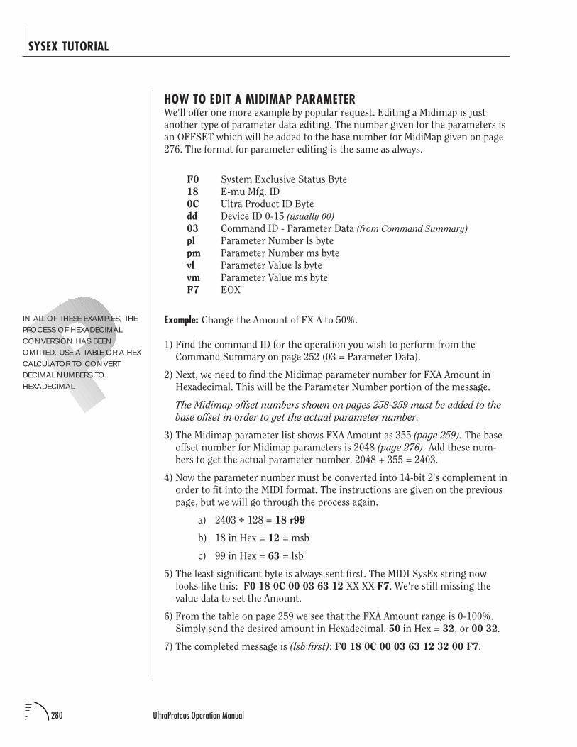
280 UltraProteus Operation Manual
SYSEX TUTORIAL
HOW TO EDIT A MIDIMAP PARAMETERWe'll offer one more example by popular request. Editing a Midimap is just
another type of parameter data editing. The number given for the parameters is
an OFFSET which will be added to the base number for MidiMap given on page
276. The format for parameter editing is the same as always.
F0 System Exclusive Status Byte
18 E-mu Mfg. ID
0C Ultra Product ID Byte
dd Device ID 0-15 (usually 00)
03 Command ID - Parameter Data (from Command Summary)
pl Parameter Number ls byte
pm Parameter Number ms byte
vl Parameter Value ls byte
vm Parameter Value ms byte
F7 EOX
Example: Change the Amount of FX A to 50%.
1) Find the command ID for the operation you wish to perform from the
Command Summary on page 252 (03 = Parameter Data).
2) Next, we need to find the Midimap parameter number for FXA Amount in
Hexadecimal. This will be the Parameter Number portion of the message.
The Midimap offset numbers shown on pages 258-259 must be added to the
base offset in order to get the actual parameter number.
3) The Midimap parameter list shows FXA Amount as 355 (page 259). The base
offset number for Midimap parameters is 2048 (page 276). Add these num-
bers to get the actual parameter number. 2048 + 355 = 2403.
4) Now the parameter number must be converted into 14-bit 2's complement in
order to fit into the MIDI format. The instructions are given on the previous
page, but we will go through the process again.
a) 2403 ÷ 128 = 18 r99
b) 18 in Hex = 12 = msb
c) 99 in Hex = 63 = lsb
5) The least significant byte is always sent first. The MIDI SysEx string now
looks like this: F0 18 0C 00 03 63 12 XX XX F7. We're still missing the
value data to set the Amount.
6) From the table on page 259 we see that the FXA Amount range is 0-100%.
Simply send the desired amount in Hexadecimal. 50 in Hex = 32, or 00 32.
7) The completed message is (lsb first): F0 18 0C 00 03 63 12 32 00 F7.
IN ALL OF THESE EXAMPLES, THEPROCESS OF HEXADECIMALCONVERSION HAS BEENOMITTED. USE A TABLE OR A HEXCALCULATOR TO CONVERTDECIMAL NUMBERS TOHEXADECIMAL.
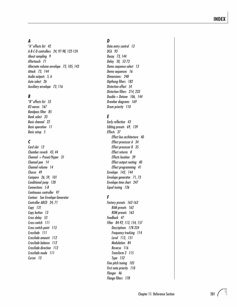
281Chapter 11: Reference Section
INDEX
A“A” effects list 42A-B-C-D controllers 24, 97-98, 122-124About sampling 9Aftertouch 71Alternate volume envelope 73, 105, 143Attack 73, 144Audio outputs 5, 6Auto select 26Auxiliary envelope 73, 116
B“B” effects list 53B3 waves 167Bandpass filter 85Bank select 33Basic channel 22Basic operation 11Basic setup 5
CCard slot 12Chamber reverb 43, 44Channel -> Preset/Hyper 31Channel pan 14Channel volume 14Chorus 49Compare 26, 59, 101Conditional jump 120Connections 5-8Continuous controller 97Contour See Envelope GeneratorController ABCD 24, 71Copy 131Copy button 13Cross delay 53Cross-switch 111Cross-switch point 113Crossfade 111Crossfade amount 112Crossfade balance 112Crossfade direction 112Crossfade mode 111Cursor 13
DData entry control 13DCA 93Decay 73, 144Delay 50, 53 73Demo sequence select 13Demo sequences 16Dimensions: 248Dipthong filters 182Distortion effect 54Distortion filters 214, 233Double + Detune 106, 144Drawbar diagrams 169Drum priority 110
EEarly reflection 43Editing presets 69, 139Effects 37
Effect bus architecture 40Effect processor A 34Effect processor B 35Effect returns 8Effects location 39Effect output routing 40Effect programming 41
Envelope 143, 144Envelope generator 71, 73Envelope time chart 247Equal tuning 126
FFactory presets 162-163
RAM presets 162ROM presets 163
Feedback 47Filter 84-92, 113, 154, 157
Descriptions 178-234Frequency tracking 114Level 113, 151Modulation 84Reverse 116Transform 2 115Type 152
Fine pitch tuning 105First note priority 110Flanger 46Flange filters 178
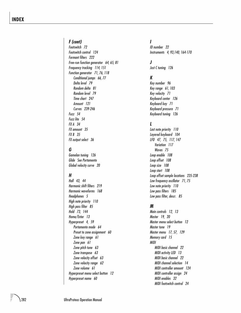
282 UltraProteus Operation Manual
INDEX
F (cont)Footswitch 72Footswitch control 124Formant filters 222Free-run function generator 64, 65, 81Frequency tracking 114, 151Function generator 71, 76, 118
Conditional jumps 66, 77Delta level 79Random delta 81Random level 79Time chart 247Amount 121Curves 239-246
Fuzz 54Fuzz lite 54FX A 34FX amount 35FX B 35FX output select 36
GGamelan tuning 126Glide See PortamentoGlobal velocity curve 20
HHall 43, 44Harmonic shift filters 219Harmonic waveforms 168Headphones 5High note priority 110High pass filter 85Hold 73, 144Home/Enter 13Hyperpreset 4, 59
Portamento mode 64Preset to zone assignment 60Zone key range 61Zone pan 61Zone pitch tune 63Zone transpose 63Zone velocity offset 63Zone velocity range 62Zone volume 61
Hyperpreset menu select button 12Hyperpreset name 60
IID number 22Instruments 4, 93,140, 164-170
JJust C tuning 126
KKey number 96Key range 61, 103Key velocity 71Keyboard center 126Keyboard key 71Keyboard pressure 71Keyboard tuning 126
LLast note priority 110Layered keyboard 104LFO 47, 75, 117, 147
Variation 117Waves 75
Loop enable 108Loop offset 108Loop size 108Loop start 108Loop offset sample locations 235-238Low frequency oscillator 71, 75Low note priority 110Low pass filters 185Low pass filter, descr. 85
MMain controls 12, 13Master 19, 20Master menu select button 12Master tune 19Master menu 17, 57, 129Memory card 15MIDI
MIDI basic channel 22MIDI activity LED 13MIDI basic channel 22MIDI channel selection 14MIDI controller amount 124MIDI controller assign 24MIDI enables 32MIDI footswitch control 24
283Chapter 11: Reference Section
INDEX
M (cont)MIDI implementation chart 249MIDI in 5, 6, 7MIDI mode 22MIDI mode change 22MIDI modes 22MIDI out 6MIDI program change map 23MIDI realtime controls 97MIDI specifications 249-280MIDI sysex tutorial 277-280MIDI sysex packet delay 25
Midimap 29Midimap pan 31Midimap volume 31Menu select button 12Name 31Select 15, 30
Midipatch 72, 97Mix select 127Modulation 70Modulation sources 71, 95, 123Mono mode 22Morph 89-92, 114, 151Morph offset 114, 151Multi mode 22Multi-timbral operation 16
NNontranspose 108Notch filters 185Notch filter, descr. 86Note-on modulation control 71, 94, 122
OOrgan waveforms 171Omni mode 22Only, effect mode 35Output impedance: 248Output level: 214Output mix 31
PPan 61, 93Parametric filters 87, 217Percussion instrument locations 173-177Percussion instruments 166-167Performance setup 7
Phaser 48Pitch tune 63Pitch wheel 124Pitch bend range 124Pitch wheel 71Plates, reverb 43Poles 86Poly mode 22Polyphonic key pressure 71Portamento 110Portamento mode 64, 111Portamento rate 110Portamento shape 110Power 8Power requirements: 248Power switch 13Preset 4Preset menu 101Preset menu select button 12Preset name 102Presets 160Pressure amount 124Primary alternate envelope 106Primary key range 104Primary filter type 113Primary instrument 102Program map select 34Program selection 14Programming basics 67Proteus sysex 26
QQ 86
RRain effect 43Random LFO wave 75Realtime control 97Realtime modulation 71, 95, 123, 149Reference section 161Release 73, 144Reverb 42, 43Reverse sound 107Ring modulator 55
284 UltraProteus Operation Manual
INDEX
SSample rate 248Sampled sounds listing 164Sampling 9Save 147
Save hyperpreset 66Save midimap 36Save preset 127
Sawtooth, LFO wave 75Secondary alternate envelope 106Secondary filter type 113Secondary key range 104Secondary instrument 102Send, MIDI data 24Setup, UltraProteus 5Sequencer, using UltraProteus 158-159Shimmer effect 43Sine, LFO wave 75Solo mode 109Solo mode priority 110Sound delay 107, 145Sound reverse 107Sound splicing 146Sound start 107, 145Split keyboard 104Square, LFO wave 75Studio setup 6Sub 1 & 2 8Sustain 73, 144Synth mode 109Synthesizer waves 169Sysex 24, 251-280
TTap level 50Technical specifications 248Tone 84, 93Tone filter 84, 93Tracking, filter freq. 90, 114Tracking filters 216Transform 2 152Transpose 19, 63, 105Tremolo 75Triangle, LFO wave 75Tuning
Coarse & fine tuning 63, 105Tuning to other instruments 19User key tuning 20, 126
UUser key tuning 20
VVallotti tuning 126Variable slope filters 190, 215Variation, LFO 117Velocity curve 96, 125Velocity offset 63Velocity range 62Vibrato 75Viewing angle 26Vocal filters 221Volume 61, 103, 141Volume Control 12
WWeight: 248Wind mode 109
ZZ-plane filter 84, 89, 93, 151Z-plane filter descriptions 178-234Zone 4, 59
110/220 819-tone tuning 126
285Chapter 11: Reference Section
WARRANTY
Please read this warranty, as it gives you specific legal rights.
Length of WarrantyThis warranty covers all defects in materials and workmanship for a period of one year from thedate of purchase by the original owner, provided that the Warranty Registration Card is filled outand returned to E-mu Systems within 14 days from the date of purchase. Cases may arise whereE-mu's Service Department or one of E-mu's authorized service centers will ask for a copy ofyour sales receipt to facilitate warranty service. Please keep your purchase receipt in a safe place.
E-mu Systems does not cover:• Damages due to improper or inadequate maintenance, accident, abuse, misuse, alteration,
unauthorized repairs, tampering, or failure to follow normal operating procedures as outlinedin the owner's manual.
• Deterioration or damage of the cabinet.
• Damages occurring during any shipment of the product for any reason.
• An E-mu product that has in any way been modified by anyone other than E-mu Systems, Inc.
Limitation of Implied WarrantiesNo warranty is expressed or implied. E-mu Systems specifically disclaims the implied warrantiesof merchantability and fitness for a particular purpose.
Exclusion of Certain DamagesE-mu Systems' liability for a product found defective is limited to repair or replacement of theunit, at E-mu's option. In no event shall E-mu Systems be liable for damages based on inconven-ience, whether incidental or consequential, loss of use of the unit, loss of time, interruptedoperation or commercial loss, or any other consequential damages.
Some states do not allow limitation of the duration of implied warranties or the exclusion orlimitation of incidental or consequential damages, so the above limitations and exclusions maynot apply to you.
How To Obtain Warranty ServiceAll E-mu products are manufactured with the highest standards of quality. If you find that yourinstrument does require service, it may be done by an authorized E-mu service center. If you areunable to locate a service center in your area, please contact E-mu Systems Service Departmentat (408) 438-1921. They will either refer you to an authorized service center or ask that youreturn your instrument to the factory. When returning an instrument to the factory, you will beissued a Return Authorization number (RA). Please label all cartons, shipping documents andcorrespondence with this number. E-mu suggests you carefully and securely pack your instru-ment for return to the factory. Mark the outside of the shipping carton clearly with your RAnumber. Send to E-mu Systems, Inc. 1600 Green Hills Road, Scotts Valley, California, 95066.You must pre-pay shipping charges to the service location. E-mu Systems will pay returnshipping fees. You will be responsible for any damage or loss sustained during shipment in anydirection.
11/92

286 UltraProteus Operation Manual
NOTES