Embed Size (px)
Citation preview
JOURNAL OF LIGHTWAVE TECHNOLOGY, VOL. 19, NO. 4, APRIL 2001 471
Ultralong Lightwave Systems with IncompleteDispersion Compensations
Senfar Wen and Tsung-Kun Lin
Abstract—Ultralong nonreturn-to-zero optical transmissionsystems with incomplete dispersion compensations are studied.The dispersion of transmission fiber is periodically under- or over-compensated. Postdispersion compensation (PDC) at the receiveris used to compensate for the residual dispersion caused by incom-plete compensation and to tailor the signal pulse shape. Formulasestimating the change of pulse width in the absence of amplifiernoise during signal transmission and after PDC are given. Duringsignal transmission, pulse width may be compressed or broadenedby the combined effect of the dispersion and self-phase modulation(SPM). The change of pulse width nearly increases with the squareof the distance during signal transmission. With amplifier noise,system performance evaluated by factor is studied. Severaltypes of transmission fibers are considered. The factor can besignificantly improved by proper PDC. Signal pulse is compressedwhen PDC is optimized. The characteristics of the maximumfactor and the residual dispersion are studied, in which PDCis optimized. The results show that to achieve the best systemperformance, fiber dispersion should be undercompensated forpositive dispersion parameter and overcompensated for negativedispersion parameter. The optimal fiber dispersion lies in therange from 4 to 10 ps/km/nm for the considered systems, and theoptimal ratio of residual dispersion and fiber dispersion is about1%.
Index Terms—Fiber dispersion compensation, fiber nonlin-earity, optical communication, self-phase modulation (SPM).
I. INTRODUCTION
NOWADAYS, dispersion compensation is typically usedin the design of high-speed and long-distance lightwave
communication system to restore the signal distortion causedby fiber dispersion [1]–[8]. The dispersion compensation can beaccomplished by arranging the dispersion of the transmissionfiber [1]–[4], [6] or by the use of dispersive elements in whichtheir signs of dispersions are opposite to the transmissionfiber [5]–[8]. For a single-channel system, complete dispersioncompensation can be achieved [1], [2]. For a wavelengthdivision multiplexing (WDM) system, all the channels arehard to completely compensate [7], [8]. However, it is shownthat because of the self-phase modulation (SPM) effect, thedispersion should be slightly undercompensated [5]. In [5], a360-km standard (1.3-m zero dispersion) fiber transmissionsystem with 1.55-m wavelength is considered. In addition, tosuppress the four-wave mixing (FWM) among signal channelsfor a WDM system, fiber dispersion must not be completely
Manuscript received April 18, 2000; revised December 12, 2001. This workwas supported by National Science Council, R.O.C., under Contract NSC89-2215-E-216-001.
The authors are with the Department of Electrical Engineering, Chung HuaUniversity, Hsinchu, Taiwan, R.O.C.
Publisher Item Identifier S 0733-8724(01)02763-3.
compensated [9], [10]. In this paper, we will explicitly studythe ultralong single-channel systems in which fiber dispersionsare not completely compensated. For an ultralong system,dispersion-shifted fiber (DSF) is usually used [2], [3], [5],in which fiber dispersion is low in the 1.55-m wavelengthregime. Recently, high-dispersion fibers have been consideredfor WDM systems [7], [8] because the FWM and cross-phasemodulation (XPM) effects among different wavelength chan-nels can be reduced [9]–[12]. The single-channel systems withhigh dispersion fibers are also considered in this paper. Asthe nonlinear effects among different wavelength channels arereduced for the WDM systems with high dispersion fibers,the results for the single-channel systems shown in this papershould be helpful for designing the WDM systems.
Without fiber nonlinearities, the effect of incomplete disper-sion compensation on the signal pulse width can be analyticallyand exactly evaluated. However, since fiber nonlinearities im-pair the signal restoration even when dispersion is completelycompensated, the combined effect of the fiber nonlinearities andthe residual dispersion owing to incomplete dispersion com-pensation is complicated. The most significant nonlinear effectis Kerr nonlinearity, which causes signal-noise FWM [13] andSPM. Because there are no analytic solutions for the wave equa-tion including Kerr effect, numerical simulation is required toobtain the exact behavior of the pulse along the nonlinear fiber[3]. There are attempts to analytically and approximately eval-uate the signal pulse width along the nonlinear fiber for a single-channel system. In the lossless case, the root-mean-square (rms)width of the pulse along the fiber of uniform dispersion andwithout dispersion compensation can be derived [14], [15]. In-cluding fiber loss and nonuniform dispersion, an-parameterapproximation can be used to analytically evaluate the systemperformance under the condition that the pulse shape is slightlydistorted [16]. Recently, a simple method is used to estimatethe pulse width by considering the average delay time withinhalf a pulse width caused by the velocity change due to thefrequency chirping induced by SPM [17]. Though slight pulseshape distortion is also assumed in this method, the approxi-mate results agree to numerical results well even when this as-sumption is invalid. In [17], bi-end compensation configuration(BECC) is considered, where two dispersive elements are placedat the input and output ends of the transmission fiber, respec-tively, for every compensation period. The total dispersion ofthe two dispersive elements is chosen to completely compen-sate for the accumulated second-order fiber dispersion withina compensation period. It is found that by tailoring the pulsecompressibility owing to the combined effect of SPM and dis-persion, the system performance can be improved. We will use
0733–8724/01$10.00 ©2001 IEEE
472 JOURNAL OF LIGHTWAVE TECHNOLOGY, VOL. 19, NO. 4, APRIL 2001
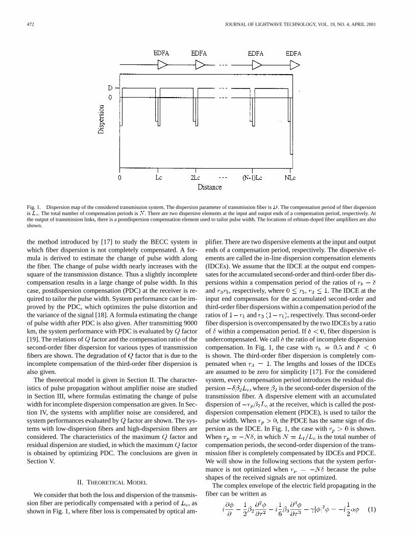
Fig. 1. Dispersion map of the considered transmission system. The dispersion parameter of transmission fiber isD. The compensation period of fiber dispersionisL . The total number of compensation periods isN . There are two dispersive elements at the input and output ends of a compensation period, respectively. Atthe output of transmission links, there is a postdispersion compensation element used to tailor pulse width. The locations of erbium-doped fiber amplifiers are alsoshown.
the method introduced by [17] to study the BECC system inwhich fiber dispersion is not completely compensated. A for-mula is derived to estimate the change of pulse width alongthe fiber. The change of pulse width nearly increases with thesquare of the transmission distance. Thus a slightly incompletecompensation results in a large change of pulse width. In thiscase, postdispersion compensation (PDC) at the receiver is re-quired to tailor the pulse width. System performance can be im-proved by the PDC, which optimizes the pulse distortion andthe variance of the signal [18]. A formula estimating the changeof pulse width after PDC is also given. After transmitting 9000km, the system performance with PDC is evaluated byfactor[19]. The relations of factor and the compensation ratio of thesecond-order fiber dispersion for various types of transmissionfibers are shown. The degradation offactor that is due to theincomplete compensation of the third-order fiber dispersion isalso given.
The theoretical model is given in Section II. The character-istics of pulse propagation without amplifier noise are studiedin Section III, where formulas estimating the change of pulsewidth for incomplete dispersion compensation are given. In Sec-tion IV, the systems with amplifier noise are considered, andsystem performances evaluated byfactor are shown. The sys-tems with low-dispersion fibers and high-dispersion fibers areconsidered. The characteristics of the maximumfactor andresidual dispersion are studied, in which the maximumfactoris obtained by optimizing PDC. The conclusions are given inSection V.
II. THEORETICAL MODEL
We consider that both the loss and dispersion of the transmis-sion fiber are periodically compensated with a period of, asshown in Fig. 1, where fiber loss is compensated by optical am-
plifier. There are two dispersive elements at the input and outputends of a compensation period, respectively. The dispersive el-ements are called the in-line dispersion compensation elements(IDCEs). We assume that the IDCE at the output end compen-sates for the accumulated second-order and third-order fiber dis-persions within a compensation period of the ratios ofand , respectively, where , . The IDCE at theinput end compensates for the accumulated second-order andthird-order fiber dispersions within a compensation period of theratios of and , respectively. Thus second-orderfiber dispersion is overcompensated by the two IDCEs by a ratioof within a compensation period. If , fiber dispersion isundercompensated. We callthe ratio of incomplete dispersioncompensation. In Fig. 1, the case with andis shown. The third-order fiber dispersion is completely com-pensated when . The lengths and losses of the IDCEsare assumed to be zero for simplicity [17]. For the consideredsystem, every compensation period introduces the residual dis-persion , where is the second-order dispersion of thetransmission fiber. A dispersive element with an accumulateddispersion of at the receiver, which is called the post-dispersion compensation element (PDCE), is used to tailor thepulse width. When , the PDCE has the same sign of dis-persion as the IDCE. In Fig. 1, the case with is shown.When , in which is the total number ofcompensation periods, the second-order dispersion of the trans-mission fiber is completely compensated by IDCEs and PDCE.We will show in the following sections that the system perfor-mance is not optimized when because the pulseshapes of the received signals are not optimized.
The complex envelope of the electric field propagating in thefiber can be written as
(1)
WEN AND LIN: ULTRALONG LIGHTWAVE SYSTEMS WITH INCOMPLETE DISPERSION COMPENSATIONS 473
wherethird-order dispersion of the transmission fiber;nonlinear coefficient that is responsible for SPM andsignal-noise FWM;fiber loss.
The dispersion parameter . The electric fieldenvelope of an input pulse is taken to be
(2)
wherepeak power;relates to pulse width;parameter relating to pulse shape.
In this paper, we consider nonreturn-to-zero (NRZ) signalformat and take . Thus, , where is bitrate. With such a choice, the pulse width (full-width half-max-imum) and the average power of the NRZ pulsetrain is 0.5 . In the following, we take the signal wavelength
m, bit rate , compensation periodkm, total transmission distance km,
mW, and . In this paper, various fiber disper-sions are considered. Since the effect of incomplete dispersioncompensation on system performance is interested, we willonly change the value of and keep the other fiber parametersthe same for simplicity. We take the fiber loss dB/km,third-order dispersion ps km, and nonlinearcoefficient W km for all the transmissionfibers considered below. Equation (1) is numerically solved bysplit-step Fourier method [20].
III. N OISELESSCASE
When the pulse shape distortion caused by the residual dis-persion contributed from all the compensation periods is neg-ligible, we can follow the procedures given in [17] to derivethe change of pulse width at the output of the transmission andafter PDC. For the considered pulse given by (2), the root-mean-square (rms) pulse width along the fiber without nonlinearitiescan be analytically derived [21]. In this linear case, for ,the change of rms pulse width at the output of theth compen-sation period is given by
(3)
where is the initial rms pulse width. For negli-gible pulse distortion, it requires that , and we have
(4)
When (4) is valid, half the change of pulse width at the outputof the th compensation period owing to the combined effect ofSPM and dispersion can be derived as
(5)
where ,, and
(6)
for . In (5), the first term represents thechange of pulse width when fiber dispersion of every compensa-tion period is completely compensated; the second term comesfrom the combined effect of SPM and the residual dispersion ofevery compensation period. For the numerical parameters givenabove, in (5), the value of the first term is much less than thesecond term and, therefore, the change of pulse width nearly in-creases with the square of transmission distance. After signaltransmission, half the change of pulse width at the output ofPDCE is given by (5) except that is replaced by and isreplaced by
(7)
Proper pulse compression improves system performance. Thepulse is compressed when . It was found that closelyrelates to the change of rms pulse width [17]. We define thechange ratios of pulse width as
(8)
(9)
where is the rms pulse width obtained by numerically solvingwave equation by the split-step Fourier method.
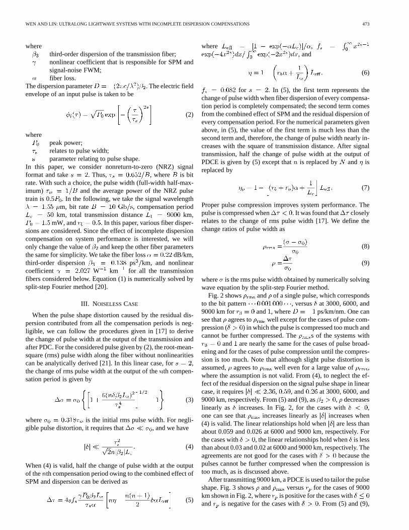
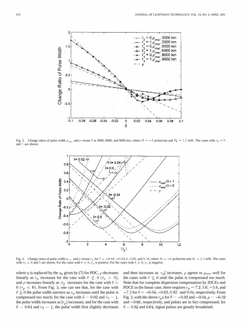
Fig. 2 shows and of a single pulse, which correspondsto the bit pattern , versus at 3000, 6000, and9000 km for and , where ps/km/nm. One cansee that agrees to well except for the cases of pulse com-pression ( ) in which the pulse is compressed too much andcannot be further compressed. The s of the systems with
and are nearly the same for the cases of pulse broad-ening and for the cases of pulse compression until the compres-sion is too much. Note that although slight pulse distortion isassumed, agrees to well even for a large value of ,where the assumption is not valid. From (4), to neglect the ef-fect of the residual dispersion on the signal pulse shape in linearcase, it requires , , and at 3000, 6000, and9000 km, respectively. From (5) and (9), as , decreaseslinearly as increases. In Fig. 2, for the cases with ,one can see that increases linearly as increases when(4) is valid. The linear relationships hold when are less thanabout 0.059 and 0.026 at 6000 and 9000 km, respectively. Forthe cases with , the linear relationships hold whenis lessthan about 0.03 and 0.02 at 6000 and 9000 km, respectively. Theagreements are not good for the cases with because thepulses cannot be further compressed when the compression istoo much, as is discussed above.
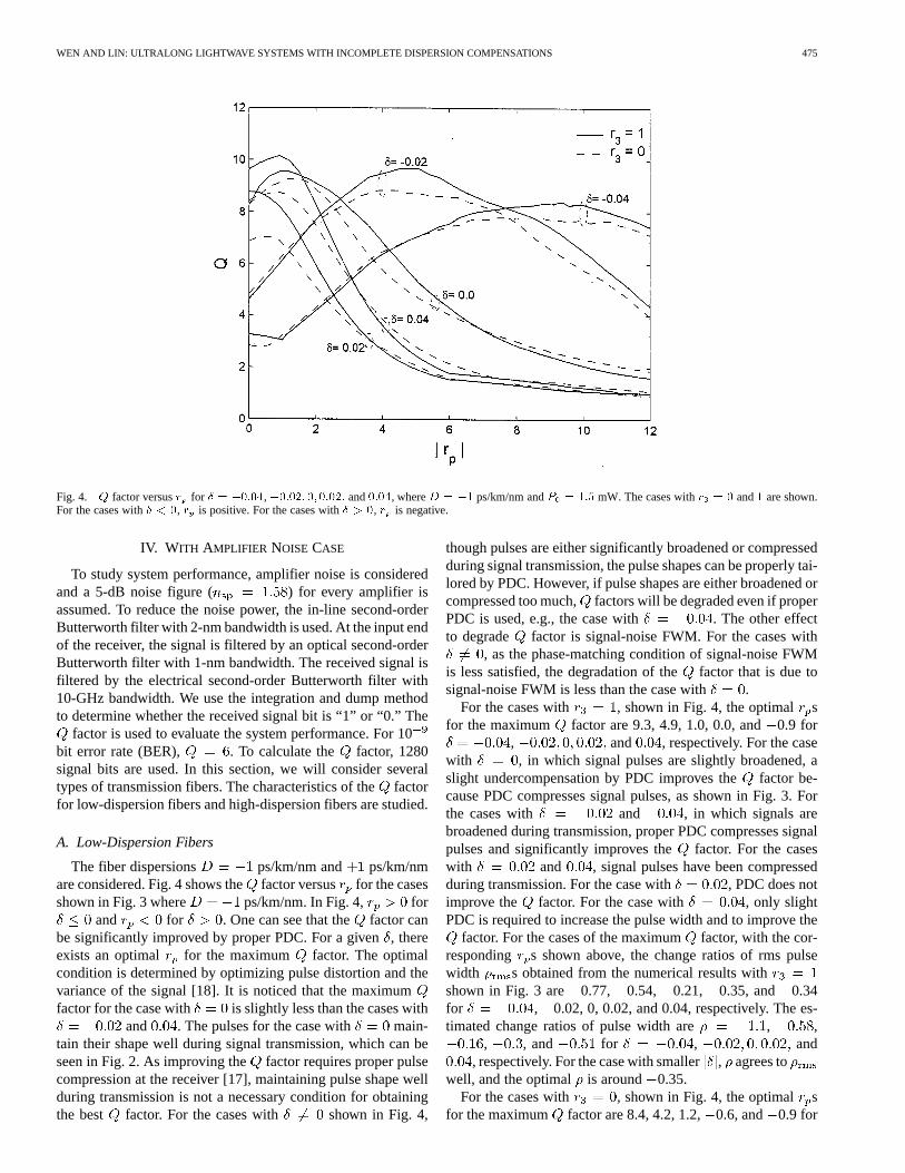
After transmitting 9000 km, a PDCE is used to tailor the pulseshape. Fig. 3 showsand versus for the cases of 9000km shown in Fig. 2, where is positive for the cases withand is negative for the cases with . From (5) and (9),
474 JOURNAL OF LIGHTWAVE TECHNOLOGY, VOL. 19, NO. 4, APRIL 2001
Fig. 2. Change ratios of pulse width� and� versus� at 3000, 6000, and 9000 km, whereD = �1 ps/km/nm andP = 1:5 mW. The cases withr = 0
and1 are shown.
Fig. 3. Change ratios of pulse width� and� versusr for � = �0:04,�0:02; 0; 0:02; and0:04, whereD = �1 ps/km/nm andP = 1:5 mW. The caseswith r = 0 and1 are shown. For the cases with� < 0, r is positive. For the cases with� > 0, r is negative.
where is replaced by the given by (7) for PDC, decreaseslinearly as increases for the case with ;and increases linearly as increases for the case with
. From Fig. 3, one can see that, for the case withthe pulse width narrows as increases until the pulse is
compressed too much; for the case with and ,the pulse width increases as increases; and for the case with
and , the pulse width first slightly decreases
and then increases as increases. agrees to well forthe cases with until the pulse is compressed too much.Note that for complete dispersion compensation by IDCEs andPDCE in the linear case, there requires , and
for , and respectively. FromFig. 3, with the above s for and ,and , respectively, and pulses are in fact compressed; for
and , signal pulses are greatly broadened.
WEN AND LIN: ULTRALONG LIGHTWAVE SYSTEMS WITH INCOMPLETE DISPERSION COMPENSATIONS 475
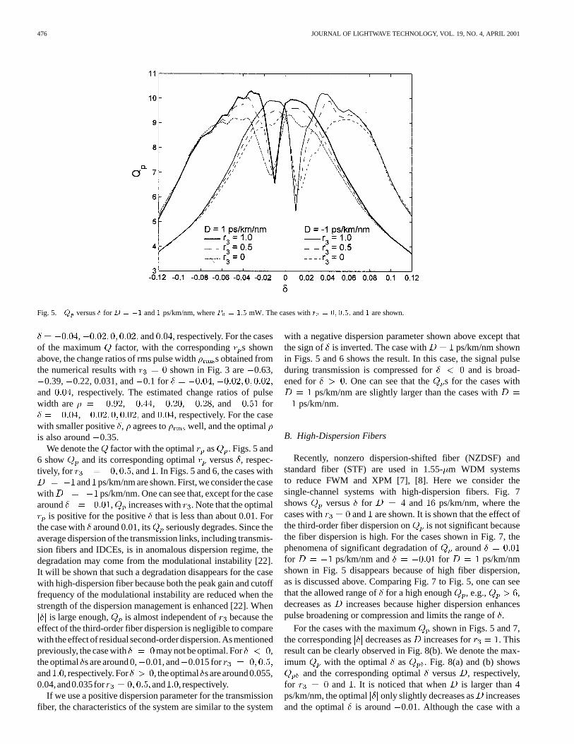
Fig. 4. Q factor versusr for � = �0:04,�0:02; 0; 0:02; and0:04, whereD = �1 ps/km/nm andP = 1:5 mW. The cases withr = 0 and1 are shown.For the cases with� < 0, r is positive. For the cases with� > 0, r is negative.
IV. WITH AMPLIFIER NOISE CASE
To study system performance, amplifier noise is consideredand a 5-dB noise figure ( ) for every amplifier isassumed. To reduce the noise power, the in-line second-orderButterworth filter with 2-nm bandwidth is used. At the input endof the receiver, the signal is filtered by an optical second-orderButterworth filter with 1-nm bandwidth. The received signal isfiltered by the electrical second-order Butterworth filter with10-GHz bandwidth. We use the integration and dump methodto determine whether the received signal bit is “1” or “0.” The
factor is used to evaluate the system performance. For 10bit error rate (BER), . To calculate the factor, 1280signal bits are used. In this section, we will consider severaltypes of transmission fibers. The characteristics of thefactorfor low-dispersion fibers and high-dispersion fibers are studied.
A. Low-Dispersion Fibers
The fiber dispersions ps/km/nm and ps/km/nmare considered. Fig. 4 shows thefactor versus for the casesshown in Fig. 3 where ps/km/nm. In Fig. 4, for
and for . One can see that the factor canbe significantly improved by proper PDC. For a given, thereexists an optimal for the maximum factor. The optimalcondition is determined by optimizing pulse distortion and thevariance of the signal [18]. It is noticed that the maximumfactor for the case with is slightly less than the cases with
and . The pulses for the case with main-tain their shape well during signal transmission, which can beseen in Fig. 2. As improving the factor requires proper pulsecompression at the receiver [17], maintaining pulse shape wellduring transmission is not a necessary condition for obtainingthe best factor. For the cases with shown in Fig. 4,
though pulses are either significantly broadened or compressedduring signal transmission, the pulse shapes can be properly tai-lored by PDC. However, if pulse shapes are either broadened orcompressed too much, factors will be degraded even if properPDC is used, e.g., the case with . The other effectto degrade factor is signal-noise FWM. For the cases with
, as the phase-matching condition of signal-noise FWMis less satisfied, the degradation of thefactor that is due tosignal-noise FWM is less than the case with .
For the cases with , shown in Fig. 4, the optimal sfor the maximum factor are 9.3, 4.9, 1.0, 0.0, and0.9 for
, and , respectively. For the casewith , in which signal pulses are slightly broadened, aslight undercompensation by PDC improves thefactor be-cause PDC compresses signal pulses, as shown in Fig. 3. Forthe cases with and , in which signals arebroadened during transmission, proper PDC compresses signalpulses and significantly improves the factor. For the caseswith and , signal pulses have been compressedduring transmission. For the case with , PDC does notimprove the factor. For the case with , only slightPDC is required to increase the pulse width and to improve the
factor. For the cases of the maximumfactor, with the cor-responding s shown above, the change ratios of rms pulsewidth s obtained from the numerical results withshown in Fig. 3 are 0.77, 0.54, 0.21, 0.35, and 0.34for , 0.02, 0, 0.02, and 0.04, respectively. The es-timated change ratios of pulse width are , ,
, , and for , and, respectively. For the case with smaller, agrees to
well, and the optimal is around 0.35.For the cases with , shown in Fig. 4, the optimal s
for the maximum factor are 8.4, 4.2, 1.2,0.6, and 0.9 for
476 JOURNAL OF LIGHTWAVE TECHNOLOGY, VOL. 19, NO. 4, APRIL 2001
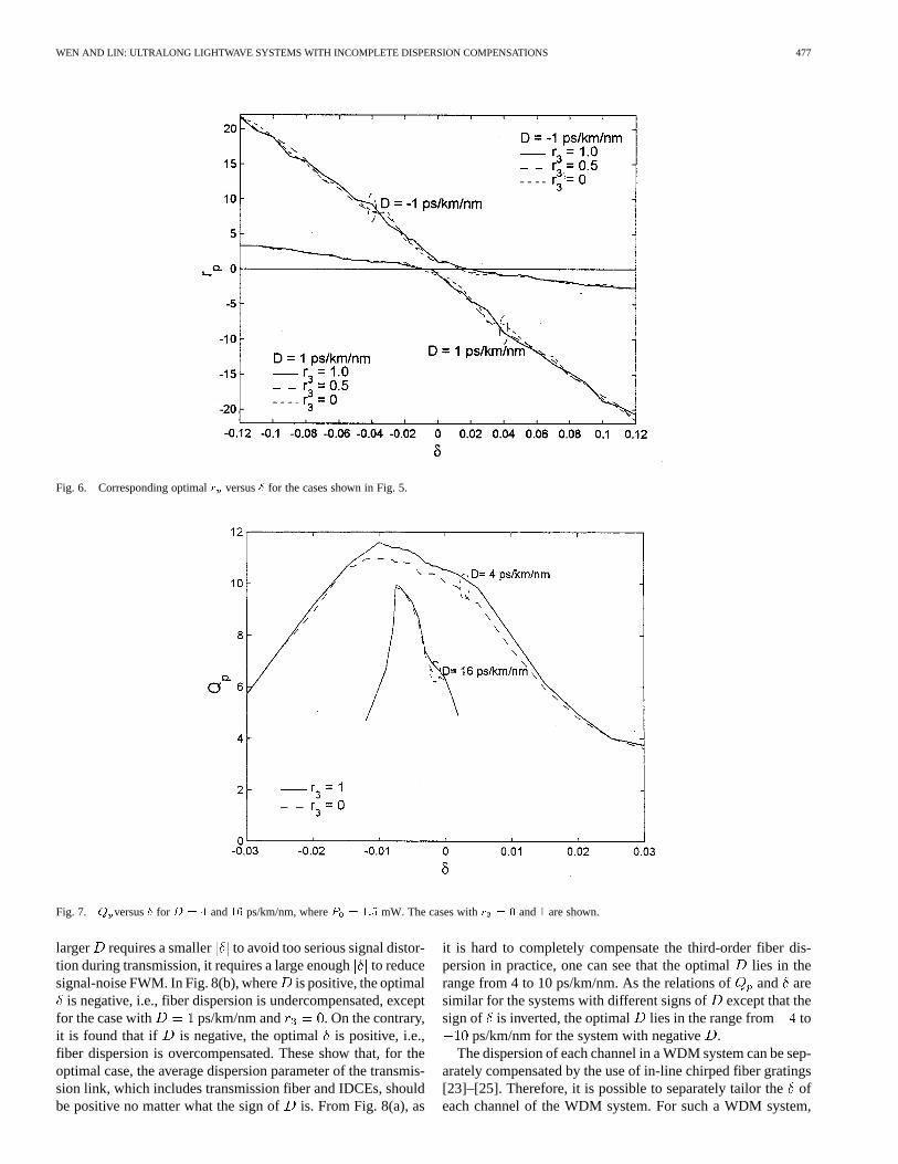
Fig. 5. Q versus� for D = �1 and1 ps/km/nm, whereP = 1:5 mW. The cases withr = 0; 0:5; and1 are shown.
, and , respectively. For the casesof the maximum factor, with the corresponding s shownabove, the change ratios of rms pulse width s obtained fromthe numerical results with shown in Fig. 3 are 0.63,
0.39, 0.22, 0.031, and 0.1 for ,and , respectively. The estimated change ratios of pulsewidth are , , , , and for
, and , respectively. For the casewith smaller positive , agrees to well, and the optimalis also around 0.35.
We denote the factor with the optimal as . Figs. 5 and6 show and its corresponding optimal versus , respec-tively, for and . In Figs. 5 and 6, the cases with
and ps/km/nm are shown. First, we consider the casewith ps/km/nm. One can see that, except for the casearound , increases with . Note that the optimal
is positive for the positive that is less than about 0.01. Forthe case with around 0.01, its seriously degrades. Since theaverage dispersion of the transmission links, including transmis-sion fibers and IDCEs, is in anomalous dispersion regime, thedegradation may come from the modulational instability [22].It will be shown that such a degradation disappears for the casewith high-dispersion fiber because both the peak gain and cutofffrequency of the modulational instability are reduced when thestrength of the dispersion management is enhanced [22]. When
is large enough, is almost independent of because theeffect of the third-order fiber dispersion is negligible to comparewith theeffectof residual second-orderdispersion.Asmentionedpreviously, the case with may not be optimal. For ,the optimal s are around 0, 0.01, and 0.015 forand , respectively. For , theoptimal sarearound0.055,0.04,and0.035for and , respectively.
If we use a positive dispersion parameter for the transmissionfiber, the characteristics of the system are similar to the system
with a negative dispersion parameter shown above except thatthe sign of is inverted. The case with ps/km/nm shownin Figs. 5 and 6 shows the result. In this case, the signal pulseduring transmission is compressed for and is broad-ened for . One can see that the s for the cases with
ps/km/nm are slightly larger than the cases withps/km/nm.
B. High-Dispersion Fibers
Recently, nonzero dispersion-shifted fiber (NZDSF) andstandard fiber (STF) are used in 1.55-m WDM systemsto reduce FWM and XPM [7], [8]. Here we consider thesingle-channel systems with high-dispersion fibers. Fig. 7shows versus for and ps/km/nm, where thecases with and are shown. It is shown that the effect ofthe third-order fiber dispersion on is not significant becausethe fiber dispersion is high. For the cases shown in Fig. 7, thephenomena of significant degradation of aroundfor ps/km/nm and for ps/km/nmshown in Fig. 5 disappears because of high fiber dispersion,as is discussed above. Comparing Fig. 7 to Fig. 5, one can seethat the allowed range offor a high enough , e.g., ,decreases as increases because higher dispersion enhancespulse broadening or compression and limits the range of.
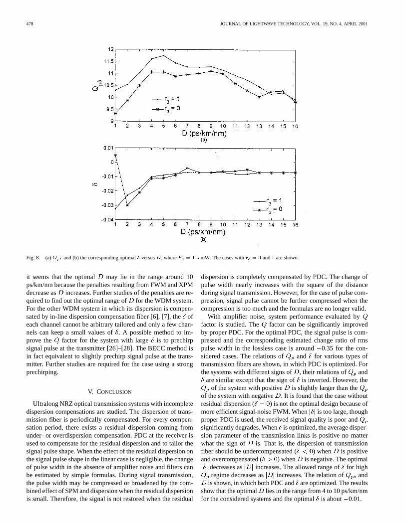
For the cases with the maximum shown in Figs. 5 and 7,the corresponding decreases as increases for . Thisresult can be clearly observed in Fig. 8(b). We denote the max-imum with the optimal as . Fig. 8(a) and (b) shows
and the corresponding optimalversus , respectively,for and . It is noticed that when is larger than 4ps/km/nm, the optimal only slightly decreases as increasesand the optimal is around 0.01. Although the case with a
WEN AND LIN: ULTRALONG LIGHTWAVE SYSTEMS WITH INCOMPLETE DISPERSION COMPENSATIONS 477
Fig. 6. Corresponding optimalr versus� for the cases shown in Fig. 5.
Fig. 7. Q versus� for D = 4 and16 ps/km/nm, whereP = 1:5 mW. The cases withr = 0 and1 are shown.
larger requires a smaller to avoid too serious signal distor-tion during transmission, it requires a large enoughto reducesignal-noise FWM. In Fig. 8(b), where is positive, the optimal
is negative, i.e., fiber dispersion is undercompensated, exceptfor the case with ps/km/nm and . On the contrary,it is found that if is negative, the optimal is positive, i.e.,fiber dispersion is overcompensated. These show that, for theoptimal case, the average dispersion parameter of the transmis-sion link, which includes transmission fiber and IDCEs, shouldbe positive no matter what the sign of is. From Fig. 8(a), as
it is hard to completely compensate the third-order fiber dis-persion in practice, one can see that the optimallies in therange from 4 to 10 ps/km/nm. As the relations of and aresimilar for the systems with different signs ofexcept that thesign of is inverted, the optimal lies in the range from to
ps/km/nm for the system with negative.The dispersion of each channel in a WDM system can be sep-
arately compensated by the use of in-line chirped fiber gratings[23]–[25]. Therefore, it is possible to separately tailor theofeach channel of the WDM system. For such a WDM system,
478 JOURNAL OF LIGHTWAVE TECHNOLOGY, VOL. 19, NO. 4, APRIL 2001
Fig. 8. (a)Q and (b) the corresponding optimal� versusD, whereP = 1:5 mW. The cases withr = 0 and1 are shown.
it seems that the optimal may lie in the range around 10ps/km/nm because the penalties resulting from FWM and XPMdecrease as increases. Further studies of the penalties are re-quired to find out the optimal range of for the WDM system.For the other WDM system in which its dispersion is compen-sated by in-line dispersion compensation fiber [6], [7], theofeach channel cannot be arbitrary tailored and only a few chan-nels can keep a small values of. A possible method to im-prove the factor for the system with large is to prechirpsignal pulse at the transmitter [26]–[28]. The BECC method isin fact equivalent to slightly prechirp signal pulse at the trans-mitter. Further studies are required for the case using a strongprechirping.
V. CONCLUSION
Ultralong NRZ optical transmission systems with incompletedispersion compensations are studied. The dispersion of trans-mission fiber is periodically compensated. For every compen-sation period, there exists a residual dispersion coming fromunder- or overdispersion compensation. PDC at the receiver isused to compensate for the residual dispersion and to tailor thesignal pulse shape. When the effect of the residual dispersion onthe signal pulse shape in the linear case is negligible, the changeof pulse width in the absence of amplifier noise and filters canbe estimated by simple formulas. During signal transmission,the pulse width may be compressed or broadened by the com-bined effect of SPM and dispersion when the residual dispersionis small. Therefore, the signal is not restored when the residual
dispersion is completely compensated by PDC. The change ofpulse width nearly increases with the square of the distanceduring signal transmission. However, for the case of pulse com-pression, signal pulse cannot be further compressed when thecompression is too much and the formulas are no longer valid.
With amplifier noise, system performance evaluated byfactor is studied. The factor can be significantly improvedby proper PDC. For the optimal PDC, the signal pulse is com-pressed and the corresponding estimated change ratio of rmspulse width in the lossless case is around0.35 for the con-sidered cases. The relations of and for various types oftransmission fibers are shown, in which PDC is optimized. Forthe systems with different signs of, their relations of and
are similar except that the sign ofis inverted. However, theof the system with positive is slightly larger than the
of the system with negative . It is found that the case withoutresidual dispersion ( ) is not the optimal design because ofmore efficient signal-noise FWM. When is too large, thoughproper PDC is used, the received signal quality is poor andsignificantly degrades. Whenis optimized, the average disper-sion parameter of the transmission links is positive no matterwhat the sign of is. That is, the dispersion of transmissionfiber should be undercompensated ( ) when is positiveand overcompensated ( ) when is negative. The optimal
decreases as increases. The allowed range offor highregime decreases as increases. The relation of and
is shown, in which both PDC andare optimized. The resultsshow that the optimal lies in the range from 4 to 10 ps/km/nmfor the considered systems and the optimalis about 0.01.
WEN AND LIN: ULTRALONG LIGHTWAVE SYSTEMS WITH INCOMPLETE DISPERSION COMPENSATIONS 479
REFERENCES
[1] N. Henmi, T. Saito, and S. Nakaya, “An arrangement of transmission-fiber dispersions for increasing the spacing between optical amplifiersin lumped repeater systems,”IEEE Photon. Technol. Lett., vol. 5, pp.1337–1340, 1993.
[2] H. Taga, S. Yamamoto, N. Edagawa, Y. Yoshida, S. Akiba, and H. Wak-abayashi, “The experimental study of the effect of fiber chromatic dis-persion upon IM-DD ultra-long distance optical communication systemswith Er-doped fiber amplifiers using a 1000 km fiber loop,”J. LightwaveTechnol., vol. 12, pp. 1455–1461, 1994.
[3] F. Metera and M. Settembre, “Comparison of the performance of opti-cally amplified transmission systems,”J. Lightwave Technol., vol. 14,pp. 1–12, 1996.
[4] J. M. Jacob, E. A. Golovchenko, A. N. Pilipetskii, G. M. Carter, andC. R. Menyuk, “10-Gb/s transmission of NRZ over 10 000 km and soli-tons over 13 500 km error-free in the same dispersion-managed system,”IEEE Photon. Technol. Lett., vol. 9, pp. 1412–1414, 1997.
[5] R. J. Nuyts, Y. K. Park, and P. Gallion, “Dispersion equalization of a10 Gb/s repeatered transmission system using dispersion compensatingfibers,” J. Lightwave Technol., vol. 15, pp. 31–42, 1997.
[6] A. R. Chraplyvy and R. W. Tkach, “Terabit/second transmission exper-iments,”IEEE J. Quantum Electron., vol. 34, pp. 2103–2108, 1998.
[7] S. Bigo and A. Bertaina, “WDM transmission experiments at32 � 10 Gb=s over nonzero dispersion-shifted fiber and stan-dard single-mode fiber,”IEEE Photon. Technol. Lett., vol. 11, pp.1316–1318, 1999.
[8] A. H. Gnauck, J. M. Wiesenfeld, L. D. Garrett, M. Eiselt, F. Forghieri, L.Arcangeli, B. Agogliata, V. Gusmeroli, and D. Scarano, “16�20-Gb=s,400-km WDM transmission over NZDSF using a slope-compensatingfiber-grating module,” IEEE Photon. Technol. Lett., vol. 12, pp.437–439, 2000.
[9] R. W. Tkach, A. R. Chraplyvy, F. Forghieri, A. H. Gnauck, and R.M. Derosier, “Four-photon mixing and high-speed WDM systems,”J.Lightwave Technol., vol. 13, pp. 841–849, 1995.
[10] W. Zeiler, F. D. Pasquale, P. Bayvel, and J. E. Midwinter, “Modelingof four-wave mixing and gain peaking in amplified WDM optical com-munication systems and networks,”J. Lightwave Technol., vol. 14, pp.1933–1942, 1996.
[11] H. J. Thiele, R. I. Killey, and P. Bayvel, “Influence of fiber dispersionand bit rate on cross-phase-modulation-induced distortion in amplifiedoptical fiber links,”Electron. Lett., vol. 34, pp. 2050–2051, 1998.
[12] M. Shtaif, M. Eiselt, and L. D. Garrett, “Cross-phase modulation distor-tion measurements in multispan WDM systems,”IEEE Photon. Technol.Lett., vol. 12, pp. 437–439, 2000.
[13] D. Marcuse, “Single-channel operation in very long nonlinear fiberswith optical amplifiers at zero dispersion,”J. Lightwave Technol., vol.9, pp. 356–361, 1991.
[14] , “RMS width of pulses in nonlinear dispersive fibers,”J. LightwaveTechnol., vol. 10, pp. 17–21, 1992.
[15] M. Florjanczyk and R. Tremblay, “RMS width of pulses in nonlineardispersive fibers: pulses of arbitrary initial form with chirp,”J. Light-wave Technol., vol. 13, pp. 1801–1806, 1995.
[16] N. Kikuchi and S. Sasaki, “Analytical evaluation technique ofself-phase-modulation effect on the performance of cascaded opticalamplifier systems,”J. Lightwave Technol., vol. 13, pp. 868–878, 1995.
[17] S. Wen, “Bi-end dispersion compensation for ultralong optical commu-nication system,”J. Lightwave Technol., vol. 17, pp. 792–798, 1999.
[18] A. N. Pilipetskii, V. J. Mazurczyk, and C. J. Chen, “The effect of dis-persion compensation on system performance when nonlinearities areimportant,”IEEE Photon. Technol. Lett., vol. 11, pp. 284–286, 1999.
[19] C. D. Anderson and J. A. Lyle, “Technique for evaluating system per-formance usingQ in numerical simulations exhibiting intersymbol in-terference,”Electron. Lett., vol. 30, pp. 71–72, 1994.
[20] G. P. Agrawal,Nonlinear Fiber Optics, 2nd ed. New York: Wiley,1995, ch. 2.
[21] , Nonlinear Fiber Optics, 2nd ed. New York: Wiley, 1995, ch. 3.[22] N. J. Smith and N. J. Doran, “Modulational instabilities in fibers with pe-
riodic dispersion management,”Opt. Lett., vol. 21, pp. 570–572, 1996.[23] K. O. Hill, F. Bilodeau, B. Malo, T. Kitagawa, S. Theriault, D. C.
Johnson, and J. Albert, “Chirped in-fiber Bragg gratings for compen-sation of optical-fiber dispersion,”Opt. Lett., vol. 19, pp. 1314–1316,1994.
[24] R. Kashyap, A. D. Ellis, D. J. Malyon, J. P. Hueting, H.-G. Froelich, A.Swanton, and D. J. Armes, “Four wavelength dispersion compensationover 125 km of single mode optical fiber at 10 Gb/s using multiple in-linestep-chirped grating,” inProc. ECOC’96, 1996, paper MoB.4.3.
[25] J.-C. Dung and S. Chi, “Dispersion compensation and gain flattened fora wavelength division multiplexing system by using chirped fiber grat-ings in an erbium-doped fiber amplifier,”Opt. Commun., vol. 162, pp.219–222, 1999.
[26] Y. Kodama and S. Wabnitz, “Compensation of NRZ signal distortion byinitial frequency shifting,”Electron. Lett., vol. 31, pp. 1761–1762, 1995.
[27] M. Murakami, H. Maeda, T. Takahashi, N. Ohkawa, and T. Imai,“Transoceanic twelve 10 Gb/s WDM signal transmission experi-ment with individual channel dispersion-and-gain compensation andprechirped RZ pulse format,”Electron. Lett., vol. 33, pp. 2145–2146,1997.
[28] J. Jeong, Y. K. Park, S. K. Kim, T. V. Nguyen, O. Mizuhara, andT.-W. Oh, “10-Gb/s transmission performance for positive- and nega-tive-chirped transmitters with the self-phase modulation effect,”IEEEPhoton. Technol. Lett., vol. 10, pp. 1307–1309, 1998.
Senfar Wenwas born in Fengyuan, Taiwan, R.O.C.,on July 29, 1961. He received the B.S. degree inelectrophysics and the M.S. and Ph.D. degrees inelectrooptical engineering from National ChiaoTung University, Taiwan, in 1983, 1985, and 1989,respectively.
In 1991, he joined the Faculty of Chung Hua Uni-versity, where he is currently a Professor of electricalengineering. His research interests are in the area offiber and nonlinear optics.
Tsung-Kun Lin was born in Ilan, Taiwan, R.O.C.,on June 15, 1973. He received the M.S. degree inelectrical engineering from Chung Hua University,Taiwan, in 2000.
His research interests include theory and applica-tion of numerical simulation technique for lightwavesystem.