Embed Size (px)
Citation preview
WIRELESS COMMUNICATIONS AND MOBILE COMPUTINGWirel. Commun. Mob. Comput. 2003; 3:663–685 (DOI: 10.1002/wcm.149)
Ultra-wideband wireless communications
Weihua Zhuang1,*,y, Xuemin (Sherman) Shen1 and Qi Bi2
1Centre for Wireless Communications (CWC), Department of Electrical and Computer Engineering, University
of Waterloo, Waterloo, Ontario N2L 3G1, Canada2Lucent Technologies Inc., 67 Whippany Road, Whippany, New Jersey 07981, USA
Summary
Ultra-wideband (UWB) communication techniques have attracted a great interest in both academia and industry in
the past few years for applications in short-range wireless mobile systems. This is due to the potential advantages
of UWB transmissions such as low power, high rate, immunity to multipath propagation, less complex transceiver
hardware, and low interference. However, tremendous R&D efforts are required to face various technical
challenges in developing UWB wireless systems, including UWB channel characterization, transceiver design,
coexistence and interworking with other narrowband wireless systems, design of the link and network layers to
benefit from UWB transmission characteristics. This paper is to provide an overview of UWB communications,
summarize the previous research results, and identify further research issues that need to be tackled. The emphasis
is placed on the commercial wireless communications. Copyright # 2003 John Wiley & Sons, Ltd.
KEY WORDS: call admission control (CAC); channel characterization; coexistence; medium access control
(MAC); monocycle waveform; interworking; transceiver structure; ultra wideband (UWB)
transmission
1. Introduction
Ultra-wideband (UWB) transmission is a widely used
technology in radar and remote sensing applications
[3] and has recently received great attention in both
academia and industry for applications in wireless
communications [5,37,38,41,75,79,94,97,116,117]. A
UWB system is defined as any radio system that has a
10-dB bandwidth larger than 25 percent of its center
frequency, or has a 10-dB bandwidth equal to or larger
than 1.5 GHz if the center frequency is greater than
6 GHz [32]. The trends that drive recent R&D activ-
ities carried out for UWB transmission for commer-
cial communication applications include [66]: (a)
increasing demand for low-cost portable devices pro-
viding high-rate transmission capability at lower
power than currently available, (b) lack of available
frequencies, and crowding in currently assigned un-
licensed frequency bands, (c) increasing availability
of wireline high-speed Internet access in enterprises,
homes and public places, and (d) decreasing semi-
conductor cost and power consumption for signal
processing. Preliminary results demonstrate that
UWB radio is a viable candidate for short-range
multiple access communications in dense multipath
environments. The preliminary approval of UWB
*Correspondence to: Weihua Zhuang, Centre for Wireless Communications (CWC), Department of Electrical and ComputerEngineering, University of Waterloo, Waterloo, Ontario N2L 3G1, Canada.yE-mail: [email protected]/grant sponsor: Natural Science and Engineering Research Council (NSERC) of Canada; contract/grant numbers:RGPIN155131 and RGPIN203560.
Copyright # 2003 John Wiley & Sons, Ltd.

technology made by Federal Communications Com-
mission (FCC) of the United States reserves the
frequency band between 3.1 and 10.6 GHz for indoor
UWB communication systems [32]; however, most of
the works reported in the open literature so far were
carried out before the FCC approval. As a result, the
frequency bands of some UWB transmission schemes
presented in this paper go beyond the FCC limits. In
general, UWB technology has many benefits due to its
ultra-wideband nature, which include the following:
1. High data rate—UWB technology is likely to pro-
vide high data rates in short- and medium-range
(such as 20 m, 50 m) wireless communications [75];
2. Less path loss and better immunity to multipath
propagation—As UWB spans over a very wide
frequency range (from very low to very high), it
has relatively low material penetration losses. On
the other hand, UWB channels exhibit extremely
frequency-selective fading, and each received sig-
nal contains a large number of resolvable multipath
components [115,118]. The fine-time resolution of
UWB signals facilitates the receiver to coherently
combine multipath signal components with path
length differentials down to about 30 cm [70].1 The
carrier-less nature of UWB signals results in less
fading, even when pulses overlap. This reduces
fade margin in link budgets [111,118];
3. Availability of low-cost transceivers—The trans-
ceiver structure may be very simple due to the
absence of the carrier. The techniques for generat-
ing UWB signals have existed for more than three
decades [90]. Recent advances in silicon process
and switching speeds make commercial low-cost
UWB systems possible [35,38,46,64,65,102].
4. Low transmit power and low interference—For a
short-range operation, the average transmit power
of pulses of duration on the order of one nanose-
cond with a low duty cycle is very low. With an
ultra-wideband spectrum bandwidth, the power
spectral density of UWB signals is extremely
low. This gives rise to the potential that UWB
systems can coexist with narrowband radio sys-
tems operating in the same spectrum without
causing undue interference. Also, UWB operates
with emission levels commensurate with common
digital devices such as laptop computers, palm
Pilots, and pocket calculators. It may further utilize
the frequency spectrum used by existing services.
On the other hand, there exist many technical
challenges in UWB deployment. These include: (a)
distortion of the received waveform from each distinct
delayed propagation path, which makes it difficult to
explore path diversity inherent in the received signal
[17]; (b) synchronization of very short pulses at the
receiver; (c) performance degradation due to multiple
access interference and narrowband jamming; (d)
employing higher order modulation schemes to im-
prove capacity or throughput; (e) development of link
and network layers to take advantage of the UWB
transmission benefits at the physical layer.
UWB technology has potentials for applications in
communications, radar and location [1,37,39,40,97].
In recent years, R&D efforts have resulted in advances
of UWB technology in areas such as antennas
[31,52,92,102], power amplifiers [60], timing chips
and synchronizers [33,59]. For wireless communica-
tions in particular, the applications and hardware that
have been developed and demonstrated in the past few
years include the following [37,97,109]: (a) For short
range operation up to 5 m, data rates up to 600 Mbps
are possible within the limits specified in the Code of
Federal Regulations for intentional radiators [107]
while introducing only negligible interference to co-
existing users; (b) At a range of 10 m with an effective
average output power of 50 mW, a simplex 2.0 GHz
data link can support a data rate of 5 Mbps at less than
10�8 bit error rate without forward error correction;
(c) At a range of 1–2 km, a full duplex 1.5 GHz hand-
held radio unit provides a data rate of up to 128 kbps
with an average output power of 640 mW; (d) At a
range beyond 16 km, a full duplex 1.3 GHz radio
system has a variable data rate of either 39 kbps or
156 kbps with an average output power of 250 mW. In
addition, a highly mobile, multimode, ad hoc wireless
communication network based on UWB technology is
under development to provide a secure, low probabil-
ity of intercept and detection, and to support en-
crypted voice/data (up to 128 kbps) and high-rate
1This approach to mitigating channel impairments is totallydifferent from some techniques used in narrowband systems.For example, a basic approach to combating frequency-selective fading in high-rate narrowband systems is topartition the signal into contiguous frequency bands, eachof which is narrow compared with the coherence bandwidthof the channel. Each of the signal components is thenmodulated onto a different subcarrier and the signal com-ponents are sent over the channel in parallel. In this way,each of the signal components experiences frequency flatfading. This can be achieved by converting the high rateserial data sequence into a number of lower rate parallelsequences and then modulating each onto a subcarrier. Aneffective method to achieve this is orthogonal frequencydivision multiplexing (OFDM).
664 W. ZHUANG, X. SHEN AND Q. BI
Copyright # 2003 John Wiley & Sons, Ltd. Wirel. Commun. Mob. Comput. 2003; 3:663–685

video (1.544 Mbps T1) transmissions. In general,
there is a tradeoff between the average power (and
correspondingly the distance) and data rate. For short
distance transmission, such as in an indoor wireless
system or a home entertainment network [124], UWB
technology has the potential to enable simple, low-
cost and high-rate applications such as digital video;
as the distance increases, UWB wireless systems are
likely to support a data rate such as 20 Mbps in local
area and wide area networks (LAN/WANs).
Even though R&D results so far have demonstrated
that UWB radio is a promising solution for high-rate
short-range wireless communications, further exten-
sive investigation, experiment, and development are
necessary towards developing effective and efficient
UWB communication systems and developing UWB
technology. This paper is to make a contribution to the
development of UWB systems.2 It provides an over-
view of UWB communications, summarizes the pre-
vious research results, and identifies further work that
should be looked into. The emphasis is placed on the
commercial wireless communications. This paper is
organized as follows: Section 2 describes the princi-
ples of UWB transmission, including impulse radio
(IR) using pulse position modulation (PPM) and pulse
amplitude modulation (PAM). In Section 3, we pre-
sent some existing models for the UWB radio channel
based on preliminary experiments. Receiver structures
and their performance are discussed in Section 4.
Section 5 is devoted to resource allocation issues at
the link layer (for medium access control) and net-
work layer for quality-of-service (QoS) provisioning,
followed by conclusions in Section 6.
2. UWB Transmission
UWB usually refers to impulse based waveforms that
can be used with different modulation schemes. The
transmitted signal consists of a train of very narrow
pulses at baseband, normally on the order of a nano-
second. Each transmitted pulse is referred to as a
monocycle. The information can be carried by the
position or amplitude of the pulses. In general, nar-
rower pulses in the time domain correspond to elec-
tromagnetic radiation of wider spectrum in the
frequency domain. Thus, the baseband train of nano-
second impulses can have a frequency spectrum
spanning from zero to several GHz, resulting in the
so called UWB transmission.
2.1. Monocycle Waveforms
The frequency-domain spectral content of a UWB
signal depends on the pulse waveform shape and the
pulse width. Typical pulse waveforms used in research
include rectangular, Gaussian, Gaussian doublet, and
Rayleigh monocycles, etc. [11,17,44,93,125]. A mono-
cycle should have zero DC component to allow it to
radiate effectively. In fact, to satisfy the UWB emission
constraint specified in FCC regulation 47 CFR Section
15.5(d), the desired frequency spectrum of the mono-
cycle waveform should be flat over a target bandwidth
not including the zero frequency.
A rectangular monocycle with width Tp and unity
energy can be represented byffiffiffiffi1Tp
q½UðtÞ � Uðt � TpÞ�,
where Uð�Þ denotes the unit step function. The rec-
tangular pulse has a large DC component, which is not
a desired property. Even so, the rectangular mono-
cycle has often been used in academic research
because of its simplicity.
A generic Gaussian pulse is given by
pgðtÞ ¼1ffiffiffiffiffiffi2�
p�
exp � 1
2
t � �
�
� �2� �
ð1Þ
where � defines the center of the pulse and � deter-
mines the width of the pulse. Some popular mono-
cycles are derived from the Gaussian pulse. The
Gaussian monocycle is the second derivative of a
Gaussian pulse, and is given by
pGðtÞ ¼ AG 1 � t � �
�
� �2� �
exp � 1
2
t � �
�
� �2� �
ð2Þ
where the parameter � determines the monocycle
width Tp. The effective time duration of the waveform
that contains 99.99% of the total monocycle energy is
Tp ¼ 7� centered at � ¼ 3:5�. The factor AG is
introduced so that the total energy of the monocycle
is normalized to unity, i.e.Rp2GðtÞdt ¼ 1. The fre-
quency spectrum of the Gaussian monocycle is
PGð f Þ ¼ AG
ffiffiffiffiffiffi2�
p�ð2��f Þ2
exp � 1
2ð2��f Þ2
� �� exp �j2�f�ð Þ
2In this paper, narrowband transmission refers to non-UWBtransmission, which includes conventional wideband trans-mission such as wideband code-division multiple access(CDMA) transmission in the third-generation cellular sys-tems.
ULTRA-WIDEBAND WIRELESS COMMUNICATIONS 665
Copyright # 2003 John Wiley & Sons, Ltd. Wirel. Commun. Mob. Comput. 2003; 3:663–685

The Gaussian doublet is a bipolar signal, consisting
of two amplitude reversed Gaussian pulses with a time
gap of Tw between the two pulses. The mathematical
expression for the monocycle is
pGDðtÞ ¼ AGD
�exp
�� 1
2
�t � �
�
�2�
� exp
�� 1
2
�t � �� Tw
�
�2� ð3Þ
which has a Fourier transform given by
PGDð f Þ ¼ 2AGD
ffiffiffiffiffiffi2�
p� sinð�f TwÞ exp � 1
2ð2��f Þ2
� �� exp
� j½2�f ð�þ 0:5TwÞ � 0:5��
�The pulse width is determined by the parameters �, �,
and Tw. The truncated pulse with Tp ¼ 14� for
Tw ¼ 7� contains 99.99% of the total monocycle
energy.
The Rayleigh monocycle is derived from the first
derivative of the Gaussian pulse and is given by
pRðtÞ ¼ AR
t � �
�2
h iexp � 1
2
t � �
�
� �2� �
ð4Þ
with the Fourier transform
PRð f Þ ¼ AR
ffiffiffiffiffiffi2�
pð2��f Þ exp
�� 1
2ð2��f Þ2
�� exp
�� jð2�f�þ 0:5�Þ
The effective time duration of the waveform that
contains 99.99% of the total monocycle energy is
Tp ¼ 7� centered at � ¼ 3:5 �, which is the same as
that of the Gaussian monocycle.
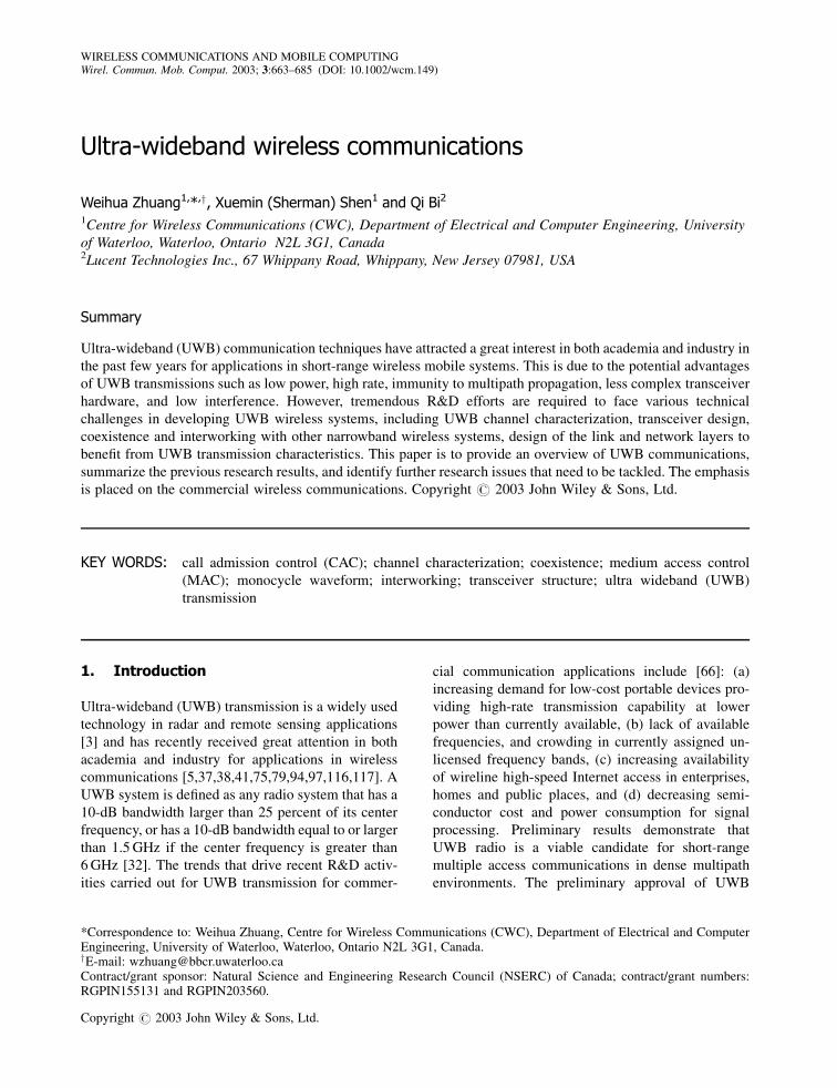
Different from the rectangular waveform, an im-
portant feature of the above monocycles is that they do
not have a DC component, which makes the radiation
of the monocycles more efficient. Figure 1 shows the
UWB monocycles and their frequency spectra in dB,
where the maximum magnitudes of the monocycles
and spectra are normalized to unity and 0 dB respec-
tively. Define the 10-dB bandwidth of the monocycles
as B10dB ¼ fH � fL, where fH and fL are the frequencies
at which the magnitude spectrum attains 1=ffiffiffiffiffi10
pof its
peak value, and the nominal center frequency as
fc ¼ ð fH þ fLÞ=2. Table I lists the 10-dB bandwidth
and center frequency for the monocycles, where
Fig. 1. The waveforms and magnitude spectra of Gaussian monocycle, Rayleigh monocycle, and Gaussian doublet withTp ¼ 1 ns and Tw ¼ 0:5 ns; (a) Monocycle waveforms; (b) Magnitude spectra.
666 W. ZHUANG, X. SHEN AND Q. BI
Copyright # 2003 John Wiley & Sons, Ltd. Wirel. Commun. Mob. Comput. 2003; 3:663–685

Tw ¼ Tp=2 for the Gaussian doublet. Note that the
Gaussian doublet has a larger out-band radiation than
the other two monocycles, even though it has a
smaller 10-dB bandwidth.
Important criteria in designing the monocycle wa-
veform include (a) simplicity of the monocycle gen-
erator and (b) minimal interference between the UWB
system and other narrowband systems coexisting in
the same frequency band (as to be discussed later in
this section).
2.2. Modulation
The two most popular UWB transmission models are
based on the concepts of time hopping spread spec-
trum (TH-SS) and direct sequence spread spectrum
(DS-SS) respectively. Data information can be modu-
lated to the UWB impulse train using pulse position
modulation (PPM) or pulse amplitude modulation
(PAM).3 For simplicity, consider binary modulation.
In both TH-SS and DS-SS UWB models, one infor-
mation bit is spread over multiple monocycles to
achieve a processing gain in reception.
In order to represent the transmitted signals, the
following mathematical symbols are introduced:
Tf —the nominal pulse repetition interval
Tc—chip interval
Ns—the number of monocycles modulated by each
information bit, referred to as spreading factor
Td —bit interval, equal to NsTf in TH-SS and to NsTcin DS-SS
fcdg—a binary pseudorandom noise (PN) code se-
quence of length Ns in DS-SS, cd 2 f�1;þ1g
Fig. 1. Continued
Table I. The 10-dB bandwidth and center frequency of the mono-cycles.
Monocycle B10 dB fc
Gaussian 1.11/Tp 1.61/TpRayleigh 1.11/Tp 1.16/TpGaussian doublet 0.83/Tp 0.94/Tp
3Here we consider binary antipodal PAM. Note that phasemodulation in general is not applicable to UWB transmis-sion due to its carrier-less nature.
ULTRA-WIDEBAND WIRELESS COMMUNICATIONS 667
Copyright # 2003 John Wiley & Sons, Ltd. Wirel. Commun. Mob. Comput. 2003; 3:663–685

fctg—a binary PN code sequence for TH, which
defines unique code phases in the interval
0; Nt�½ where NtTc < Tf and ct 2 f0; 1gj—chip index of the PN sequence
fdng—information data sequence, dn ¼ 0 for symbol
‘‘1’’ and dn ¼ 1 for symbol ‘‘0’’ in PPM, and
dn ¼ 1 for symbol ‘‘1’’ and dn ¼ �1 for
symbol ‘‘0’’ in PAM
�—an extra delay of monocycles for symbol ‘‘0’’ in
PPM
n—information bit index
pðtÞ—monocycle waveform, examples including
those given in Equations (2), (3) and (4)
Ep—monocycle energy
The transmitted signal in TH-SS using PPM is
given by
xðtÞ ¼ffiffiffiffiffiEp
p X1n¼1
XNs�1
j¼0
p½ðt � nTd � jTf � ðctÞjTc � �dnÞ�
ð5Þ
with the energy of the pulse pðtÞ being unity. On a
large scale, the time is partitioned to frames of bit
interval Td. Within each frame, there are Ns mono-
cycles. Each monocycle experiences a distinct extra
delay ðctÞjTc different from the rest of the monocycles
within the frame in order to avoid catastrophic colli-
sions in multiple access. Depending on the informa-
tion bit, all the monocycles in the frame experience an
extra common delay �ð> 0Þ for information symbol
‘0’. The ratio NtTc=Tf represents the percentage of
time in each frame over which TH is allowed. The
ratio should not be too small in order to avoid
catastrophic collisions. Similarly, the transmitted
signal in DS-SS using PPM is given by
xðtÞ ¼ffiffiffiffiffiEp
p X1n¼1
XNs�1
j¼0
ðcdÞjpðt � nTd � jTf � �dnÞ
ð6ÞThe DS-SS PPM is also referred to as hybrid DS-TH
UWB [56]. Here, we consider orthogonal PPM where
all the monocycles do not overlap, i.e. � � Tp in
Equations (5) and (6).
Correspondingly, using PAM, the transmitted signal
is
xðtÞ ¼ffiffiffiffiffiEp
p X1n¼1
XNs�1
j¼0
p½t � nTd � jTf � ðctÞjTc�dn
ð7Þ
in TH-SS and is
xðtÞ ¼ffiffiffiffiffiEp
p X1n¼1
XNs�1
j¼0
ðcdÞjpðt � nTd � jTf Þdn ð8Þ
in DS-SS. In summary, the transmitted signal can be
represented as
xðtÞ ¼ffiffiffiffiffiEp
p X1n¼1
XNs�1
j¼0
ptðt � nTd � jTf Þ ð9Þ
where the modulated monocycle ptðtÞ is a function of j
and n, and is given by
ptðtÞ ¼
p½t � ðctÞjTc � �dn� ðTH-SS PPMÞðcdÞjpðt � �dnÞ ðDS-SSP PMÞp½t � ðctÞjTc�dn ðTH-SS PAMÞðcdÞjpðtÞdn ðDS-SS PAMÞ
8>>><>>>:
ð10Þ
The transmission data rate Rs in bps is equal to
1=ðNsTf Þ in TH-SS and to 1=ðNsTcÞ in DS-SS. Given
the spreading factor Ns, the information data rate Rs
depends on the pulse repetition interval Tf or the chip
interval Tc.
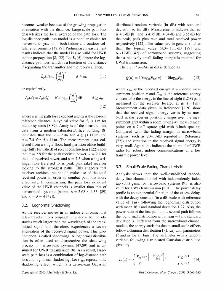
Figure 2 shows the difference between TH-SS and
DS-SS [44], where PAM is used for illustration clarity.
A similar illustration can be drawn for PPM. From the
figure, the following observations can be made:
1. In DS-SS PAM, we have Tc ¼ Tp ¼ Tf , leading to
a duty cycle of 100%. The DS-SS PAM is basically
DS-CDMA using BPSK (binary phase shift key-
ing) except that the carrier frequency is zero and
the chip pulse is the UWB monocycle. Within each
frame, the information bit is to modulate Ns evenly
distributed (in the time axis) monocycles and each
PN code chip is to determine the polarity (positive
or negative) of the corresponding monocycle after
the data modulation. Signals for different users are
to be separated through PN code correlation as in
DS-CDMA;
2. The power spectral density (psd) of the above
UWB signals can be calculated using the mathe-
matical expressions given in Reference [114]. In
DS-SS PAM, with a constant Tf , line spectrum
appears in the frequency domain and the separation
between the adjacent lines is proportional to 1=Tf .The spectrum lines are not desired as they can
introduce noticeable interference to other radio
668 W. ZHUANG, X. SHEN AND Q. BI
Copyright # 2003 John Wiley & Sons, Ltd. Wirel. Commun. Mob. Comput. 2003; 3:663–685

systems in the same frequency spectrum. This is a
drawback of DS-SS PAM as compared with the
other three schemes where the monocycles are not
evenly distributed in each frame;
3. In the other three schemes (TH-SS PPM, DS-SS
PPM, and TH-SS PAM), Tf � NtTc and Tc � Tp,
leading to a very small duty cycle (i.e.,
Tp=Tf � 1). Given the same monocycle width
Tp, Tf in DS-SS PAM is much smaller than that
in the other three schemes. As a result, the infor-
mation rate Rs in DS-SS PAM is much higher than
that in the other cases when the Tp and Ns values
are the same for all the four schemes;
4. For the same spreading factor Ns and information
data rate Rs, the repetition interval Tf and the
number of monocycles within each frame (bit
interval) are the same among all the four schemes.
However, the DS-SS PAM scheme has a much
larger monocycle width Tp (with a duty cycle of 1)
than that in the other schemes (with a duty cycle
much smaller than 1), leading to a small ratio of
peak power to average power and an overall
smaller bandwidth;
5. The psd mainly depends on the width and wave-
form of the monocycle and on whether TH-SS or
DS-SS is used. Based on the application, the
monocycle waveform can be designed for mini-
mum interference at certain frequency bands;
6. In TH-SS PPM, all the monocycles have the same
polarity and the modulation is achieved completely
by time shifting of monocycles, which is not the
case in the other schemes. Therefore, early re-
search on UWB for wireless communications fo-
cused on TH-SS PPM due to its implementation
advantage of not requiring pulse inversion
[93,116,117].
In Equations (5), (7) and (8), it is assumed that the
PN sequences are periodic with period Ns for simpli-
city of presentation. Also, higher order modulation
(such as M-ary PPM and other M-ary orthogonal
modulation) is possible [28,86,123], which achieves
a higher throughput at the expense of implementation
complexity and transmission accuracy.
In addition to using UWB monocycles in the con-
ventional UWB transmission, UWB systems using
narrowband signals have been explored as a design
alternative [24,121]. In Reference [121], UWB based
on the well-known family of frequency-hopping (FH)-
SS multiple access technique is proposed, where
multistage FH multiple access, the associated spec-
trum assignment and the residue number system
(RNS) based FH strategy are investigated and pro-
posed. The UWB based on the conventional narrow-
band signalling has the advantages of exploring
numerous well-understood and spectral-efficient tech-
niques originally developed for narrowband signalling
in order to achieve high transmission efficiency, in
addition to using elements of the existing standards. In
Reference [24] multi-bands UWB is proposed, where
Fig. 2. Comparison of TH-SS PAM and DS-SS PAM waveforms [#2002 IEEE. Reproduced from Hamalainen M, et al. Onthe UWB system coexistence with GSM 900, UMTS/WCDMA and GPS. IEEE Journal on Selected Areas in Communications
2002; 20(9): 1712–1721. DOI: 10.1109/JSAC.2002.805242, by permission of the IEEE.]
ULTRA-WIDEBAND WIRELESS COMMUNICATIONS 669
Copyright # 2003 John Wiley & Sons, Ltd. Wirel. Commun. Mob. Comput. 2003; 3:663–685

each UWB signal occupies 500 MHz of spectrum and
does not have to be an impulse train. The approach is
adaptive and scalable, and is flexible in accommodat-
ing various transmission rate requirements. Interfer-
ence mitigation techniques should be developed to
protect existing narrowband systems in UWB inter-
fering with narrowband and to ensure that UWB is
robust in narrowband interfering with UWB.
2.3. UWB Coexistence
As UWB systems will coexist with other existing
narrowband systems/standards in the same frequency
spectrum, how UWB transmission and narrowband
transmission interfere with each other is an important
issue to ensure that both these systems operate prop-
erly in the mutual interference. The information will
help to design UWB systems for a minimum mutual
interference. Initial investigation has been carried out
and reported in References [44,45,125] for a correla-
tor receiver in an additive Gaussian white noise
(AWGN) channel. The coexistence issue of UWB
systems using TH-SS PAM and DS-SS PAM (with
the same bit energy and spreading factor) has been
investigated via computer simulations [44,45], where
the narrowband systems include GSM900, UMTS/
WCDMA and GPS.4 It is concluded that the mutual
interference can be reduced by properly designing the
monocycle waveform and properly choosing its width.
In terms of the interference from UWB systems to the
narrowband systems, it is observed that: (a) UWB
systems cause less interference to the frequency
spectra of the narrowband systems when higher order
Gaussian waveforms are used (up to the third deriva-
tive of the Gaussian pulse is considered); (b) in the
GPS L1 and L2 channels, DS-SS UWB introduces
less interference than TH-SS UWB; (c) both TH-SS
and DS-SS UWB systems generate a similar level of
interference in GSM900 and UMTS/WCDMA bands.
As to the UWB transmission performance degradation
due to jamming from the narrowband systems, it is
observed that: (a) the UWB transmission performance
suffers most when the interferer spectrum overlaps
with the nominal center frequency of the UWB
systems. Thus, the UWB monocycle waveform and
bandwidth should be designed carefully to reduce
interference from a given band; (b) TH-SS UWB
outperforms DS-SS UWB at a low interference level;
(c) both TH-SS and DS-SS UWB systems have
similar performance at a high jamming power level.
In Reference [125], the effect of narrowband jamming
on TH-SS PPM systems using rectangular pulse,
Gaussian and Rayleigh monocycles is analyzed. It is
demonstrated that, comparing with narrowband DS-
SS with Gaussian chip waveform, the UWB system
using Gaussian monocycle has a significant advantage
in suppressing both narrowband and wideband inter-
ference.
Further investigation on the interference for UWB
system coexistence is necessary for more practical
UWB channels using a rake receiver, and in the
presence of multiple access interference using an
optimal or suboptimal receiver (see Section 4 for
more details of the receivers). Also, the effect of
narrowband jamming at multiple bands on UWB
transmission performance should be studied.
3. Channel Characterization
Accurate channel characterization is vital for UWB
transceiver design and for efficient utilization of the
system resources (such as frequency spectrum and
transmit power), as the propagation channel sets
fundamental limits on the performance of UWB
communication systems. Due to reflection, refraction
and scattering, wireless signals usually experience
multipath propagation. In a narrowband system, this
phenomenon leads to multipath fading, while in UWB
systems the monocycles often do not overlap because
the pulse width is often smaller than the channel
propagation delays. Extensive work has been done
in the characterization of the narrowband indoor
propagation channel [47]. Given the wideband nature
of UWB transmission, the conventional channel
models developed for narrowband transmissions are
not adequate for UWB transmission. So far, only
very limited measurement results and preliminary
investigation on the channel modelling are available
in the open literature for UWB transmission [8,21,29,
53,84,113,115,117,119,122]. In the following, we
first discuss UWB channel statistics and models
based on the measurements, and then present some
attempts to model the UWB channel using theoretical
tools.
3.1. Large-Scale Path Loss
In wireless systems, as the distance between the
transmitter and receiver increases, the received signal
4GSM stands for Global System for Mobile Communica-tions, UMTS for Universal Mobile TelecommunicationsService, and GPS for Global Positioning System
670 W. ZHUANG, X. SHEN AND Q. BI
Copyright # 2003 John Wiley & Sons, Ltd. Wirel. Commun. Mob. Comput. 2003; 3:663–685
becomes weaker because of the growing propagation
attenuation with the distance. Large-scale path loss
characterizes the local average of the path loss. The
log-distance path loss model is a popular choice for
narrowband systems in both indoor and outdoor cel-
lular environments [47,89]. Preliminary measurement
results indicate that the model is also valid for UWB
indoor propagation [8,122]. Let �LLpðdÞ denote the log-
distance path loss, which is a function of the distance
d separating the transmitter and the receiver. Then,
�LLpðdÞ /d
d0
� ��
; d � d0 ð11Þ
or equivalently,
�LLpðdÞ ¼ �LLpðd0Þ þ 10�log10
d
d0
� �dB; d � d0
ð12Þ
where � is the path loss exponent and d0 is the close-in
reference distance. A typical value for d0 is 1 m for
indoor systems [8,89]. Analysis of the measurement
data from a modern laboratory/office building [8]
indicates that the � ¼ 2:04 for d 2 [1,11] m and
� ¼ 7:4 for d> 11 m. The measurement data col-
lected from a single-floor, hard-partition office build-
ing (fully furnished) of recent construction [122] show
that � ¼ 2:9 for the peak received power, � ¼ 2:1 for
the total received power, and � ¼ 2:5 when using a 4-
finger rake (referred to as peak plus rake) receiver
locking to the strongest paths. This suggests that
receiver architectures should make use of the total
received power in order to combat path loss more
effectively. In comparison, the path loss exponent
value of the UWB channels is smaller than that of
narrowband systems (where � ¼ 2:68 � 4:33 [89]
and � ¼ 3 � 4 [42]).
3.2. Lognormal Shadowing
As the receiver moves in an indoor environment, it
often travels into a propagation shadow behind ob-
stacles much larger than the wavelength of the trans-
mitted signal and therefore, experiences a severe
attenuation of the received signal power. This phe-
nomenon is called shadowing. A lognormal distribu-
tion is often used to characterize the shadowing
process in narrowband systems [47,89] and is as-
sumed for UWB transmission [8]. As a result, large-
scale path loss is a combination of log-distance path
loss and lognormal shadowing. Let �ðdBÞ represent the
shadowing effect, which is a zero-mean Gaussian
distributed random variable (in dB) with standard
deviation �� (in dB). Measurements indicate that ��
is 4.3 dB [8], and is 4.75 dB, 4.04 dB and 3.55 dB for
the peak, peak plus rake and total received power
respectively [122]. The values are in general smaller
than the typical value (4.3�13.3 dB [89] and
6�12 dB [42]) of narrowband systems, suggesting
that a relatively small fading margin is required for
UWB transmission.
The signal quality in dB is defined as
QðuÞ ¼ 10log10EtotðuÞ � 10log10Eref ð13Þ
where Etot is the received energy at a specific mea-
surement position u and Eref is the reference energy
chosen to be the energy in the line-of-sight (LOS) path
measured by the receiver located at d0 (¼ 1 m).
Measurement data given in Reference [119] show
that the received signal energy varies by at most
5 dB as the receiver position changes over the mea-
surement grid within a room having 49 measurement
points on a 7� 7 square grid with 6-inch spacing.
Compared with the fading margin in narrowband
systems (such as 20–30 dB reported in Reference
[72]), the variation in the received signal energy is
very small. Again, this indicates the potential of UWB
radio for robust indoor communications at a low
transmit power level.
3.3. Small-Scale Fading Characteristics
Analysis shows that the well-established tapped-
delay-line channel model with independently faded
tap (bin) gains for narrowband systems [91] is also
valid for UWB transmission [8,20]. The power delay
profile is an exponential function of the excess delay,
with the decay constant (in a dB scale with reference
value of 1 ns) following the lognormal distribution
with mean 16.1 and standard deviation 1.27. Also, the
power ratio of the first path to the second path follows
the lognormal distribution with mean �4 and standard
deviation 3. Different from the narrowband channel
models, the energy statistics due to small-scale effects
follow a Gamma distribution �ð�;mÞ with parameters
� and m for all bins. The parameter m is a random
variable following a truncated Gaussian distribution
given by
fmðxÞ ¼Km exp � ðx��mÞ2
2�2m
h i; x � 0:5
0; x < 0:5
(ð14Þ
ULTRA-WIDEBAND WIRELESS COMMUNICATIONS 671
Copyright # 2003 John Wiley & Sons, Ltd. Wirel. Commun. Mob. Comput. 2003; 3:663–685

denoted by m � T N ð�m; �2mÞ, where Km is chosen so
thatR1�1 fmðxÞdx ¼ 1. Let �l ¼ 2ðl� 1Þ ns, denoting
the excess delay of the lth bin, then the parameters �m
and �2m as a function of �l are given by
�mð�lÞ ¼ 3:5 � ð�l=73Þ�2mð�lÞ ¼ 1:84 � ð�l=160Þ
The linear tapped-delay-line model is also used in
the data post-processing reported in [53], where the
Rician fading model is assumed for each tap gain.
Each complex tap gain contains a deterministic com-
ponent (s2dB) from the LOS path and a random com-
ponent (�2dB) from NLOS paths, and the k-factor in
logarithmic scale of the Rician distribution is denoted
by k (¼ s2dB � �2
dB). The k-factor is a function of the
propagation delay � and the transmitter-receiver
distance d. A linear regression line
kð�; dÞ ¼ að�Þd þ bð�Þ¼ ½asð�Þ � a�ð�Þ�d þ ½bsð�Þ � b�ð�Þ�
can be fitted to the k-factor normalized to the average
power level, where d is the logarithmic antenna
separation, and subscripts s and � are associated
with s2dB and �2
dB respectively. At � ¼ 0, að�Þ � 0
and, at � ¼ 5 ns, að�Þ ¼ �1:67. Piecewise linear re-
gression lines also apply to the parameters as, a�, bs,
and b�, given by
asð�Þ ¼ 0s� þ s
a�ð�Þ ¼ 0�� þ �
bsð�Þ ¼ 0s� þ s
b�ð�Þ ¼ 0�� þ �
Table II lists the values for the exponential
decay coefficients extracted from the measurement
data.
The root-mean-square (rms) delay spread increases
with the distance between the transmitter and receiver,
because the propagation paths become more nonuni-
form as the distance increases [122]. Also, the rms
delay increases with the path loss, likely due to the
earliest arriving multipath components being attenu-
ated and not dominating the delay spread over the
later arriving components. The rms delay spread is
5.72 ns and 4.26 ns versus distance (ranging approxi-
mately from 1 to 20 m) and path loss (ranging
approximately from 0 to 50 dB) respectively. In com-
parison, in narrowband indoor systems, the rms value
is 19 � 49 ns [78], and increases with the propagation
distance [42,47] and with the path loss [47].
3.4. Deterministic Channel Modelling
In addition to channel measurements, preliminary
research efforts have been devoted to characterizing
the UWB channel based on theoretical approaches
[81–84,106]. One important characteristic of UWB
propagation is that each path has its own impulse
response or frequency transfer function that is fre-
quency dependent [104], which is different from
narrowband transmission where the frequency inde-
pendence assumption is implied [105] and widely
adopted. One approach is based on the geometrical
theory of diffraction (GTD) which has been used in
UWB radar identification [73]. Due to the similarity
between the radar objects and the wireless channel
obstacles, the approach can be applied to UWB
channel modelling with multiple-edge scatterers and
the corresponding time-domain resolutions to lower
frequencies by including the higher-order multiple
diffractions in terms of wave number. All the multiple
diffractions are treated together and the total field is
decomposed into several leading terms, using the
scattering center model. The scattering center model
is generalized to include the scattering and diffraction
mechanisms, by introducing a frequency dependence
factor to the channel gain of each scattered signal
component. The multiple diffractions distort the UWB
signal waveform significantly and therefore, degrade
the signal-to-noise ratio at the correlator output. This
suggests that the frequency-dependent effects on the
received waveform should be taken into account in the
transceiver design, even though the effects are usually
negligible in narrowband systems. Another theoretical
approach is based on the uniform theory of diffraction
(UTD). The received waveform is modelled as a
superposition of channel significant rays, taking into
Table II. Parameters for exponential decay coefficients and [53].
� (ns) 0s (dB) s (dB) � (ns) 0
� (dB) � (dB)
0 � 6 �0.095 �1.20 0 � 28 0.0 �0.426 � 60 0.035 �1.98 28 � 60 0.015 �0.84
� (ns) 0s (dB) s (dB) � (ns) 0
� (dB) � (dB)
0 � 10 �0.00 �15.2 0 � 28 0.00 �42.710 � 60 �0.47 �10.6 28 � 60 �0.15 �38.5
672 W. ZHUANG, X. SHEN AND Q. BI
Copyright # 2003 John Wiley & Sons, Ltd. Wirel. Commun. Mob. Comput. 2003; 3:663–685

account the effects of the transmitter antenna, multi-
path propagation, and receiver antenna. For the lth
significant ray, the channel is modelled as the tandem
of three filters with the transmitter antenna impulse
response in the emission direction of the lth ray. The
lth channel impulse response takes into account not
only the attenuation but also the dispersion due to
interaction, and the receiver antenna impulse response
in the arrival direction of the lth ray, respectively. The
channel for each ray modifies the shape and amplitude
of the corresponding impulse in a realistic way. The
significant rays and their associated delays between
the transmitter and receiver are to be determined by
ray tracing. The channel transfer function associated
with each ray is determined based on UTD. Based on
the delay associated with each ray, the contribution of
each ray to the received waveform in the time domain
can be obtained from the frequency domain channel
function.
In summary, preliminary studies of UWB propaga-
tion have confirmed that the well-developed narrow-
band indoor wireless channel models or parameter
values are not appropriate for UWB propagation.
Measurement results given in [53,119,122] demon-
strate the potential of UWB radio for robust indoor
communications at a low transmit power level, which
is also confirmed by the measurements reported in
[29,113]. However, multiple diffractions are expected
to distort UWB signal waveform significantly and
therefore, degrade the transmission performance
[87]. Extensive field measurements and analysis for
various propagation environments, together with more
comprehensive theoretical modelling, are required in
order to obtain more insights of UWB channel beha-
viours and, thus, to design the transmitter and receiver
to mitigate channel impairments.
4. Receiver Techniques and TransmissionPerformance
The UWB channel introduces large-scale path loss,
shadowing, small-scale fading, and propagation delay
dispersion to the transmitted monocycle train. The
distorted waveforms arriving at the receiver are
further corrupted by multiple access interference,
narrowband jamming, and background noise. The
function of the receiver is to extract the information
bit sequence modulated on the monocycle train from
the distorted and corrupted receiving waveforms with
a high accuracy. In general, the receiver consists of a
detector and a decision device. The detector is differ-
ent from the demodulator in narrowband systems, due
to the fact that UWB transmission is carrier-less.
However, many receiver techniques of narrowband
systems for forming the decision variable can be
directly applied to UWB receivers.
The most common UWB receiver implementations
include threshold detectors, autocorrelation receivers,
and correlation or rake receivers. The threshold de-
tectors are simple to implement and are suitable for
UWB radar systems [3]. An autocorrelation receiver
correlates the received waveform with a previously
received waveform [16,50,103,104,108], which is
similar to the suboptimal differential detector for
differential phase shift keying (DPSK) in narrowband
systems. It can capture the entire received waveform
energy for a slowly varying channel without requiring
channel estimation, as the transmitter transmits a pilot
(reference) waveform to generate side information
about the channel. The receiver suffers from the
noise-on-noise effect and 3 dB loss for transmitting
the reference waveform [16]. Most research on the
receiver focuses on the correlator receiver [9,16,34,
36,85,86,101,116–118,123], which can achieve the
optimal performance. As a result, we mainly discuss
the correlator receiver in the following.
4.1. Optimum Receiver for AWGN Channel
Consider an AWGN channel in the absence of multiple
access interference. The received signal is given by
rðtÞ ¼ xðtÞ þ nðtÞ
where xðtÞ is the transmitted monocycle train given in
Equations (9) and (10), depending on the modulation
scheme used, and nðtÞ is zero-mean white Gaussian
noise with two-sided psd of N0=2. Here it is assumed
that the effects of the transmitter and receiver anten-
nas on monocycles have been compensated by the
pulse generation at the transmitter and receiver re-
spectively. The optimum receiver for the channel is a
correlator (i.e. matched filter) receiver. The receiver
block diagram is shown in Figure 3, where the
receiver locally generated monocycle signal xrðtÞ is
synchronized with the incoming monocycle train and
is given by
xrðtÞ ¼1ffiffiffiffiffiNs
pX1n¼1
XNs�1
j¼0
prðt � nTd � jTf Þ ð15Þ
ULTRA-WIDEBAND WIRELESS COMMUNICATIONS 673
Copyright # 2003 John Wiley & Sons, Ltd. Wirel. Commun. Mob. Comput. 2003; 3:663–685
where prðtÞ is a function of j and has unity energy,
given by
At the end of the nth information symbol interval,
t ¼ nTd, the decision variable is
yðnTdÞ ¼Z nTd
ðn�1ÞTdrðtÞxrðtÞdt
¼XNs�1
j¼0
Z ðn�1ÞTdþð jþ1ÞTf
ðn�1ÞTdþjTf
rðtÞxrðtÞdt
¼ ffiffiffiffiffiffiffiffiffiffiffiffiffiffiffiffiffiffiffiffiffiffiffiffið1 � �ÞNsEp
2
rþ Nn
where the ‘‘þ’’ sign is for the case that information bit
‘‘1’’ was sent and the ‘‘�’’ sign for the case that ‘‘0’’
was sent, and � (equal to 0 for PPM and to �1 for
PAM) is the correlation coefficient between the two
signals for symbols ‘‘1’’ and ‘‘0’’, respectively, NsEp
is the bit energy, and Nn ¼R nTdðn�1ÞTd nðtÞxrðtÞdt is a
Gaussian random variable with zero mean and var-
iance N0=2. Let dndn denote the detected nth transmitted
information symbol. Then, the maximum likelihood
(ML) decision rule is that: if yðnTdÞ � 0, then dndn is
‘‘1’’; otherwise, dndn is ‘‘0’’. The probability of bit error,
or bit error rate (BER), is given by [48]
Pb ¼ Q
ffiffiffiffiffiffiffiffiffiffiffiffiffiffiffiffiffiffiffiffiffiffiffiffið1 � �ÞNsEp
pN0
!ð17Þ
4.2. Rake Receiver for Frequency-SelectiveFading Channel
As discussed in Section 3, the UWB channel intro-
duces frequency-selective fading and the channel can
be modelled by a linear tapped-delay-line. Consider a
linear tapped-delay-line channel model with the max-
imum excess delay �mð>> TpÞ. For presentation
clarity, assume that Tf � Tp þ NtTc þ � þ �m and
that j�l � �l0 j � Tp for l 6¼ l0 in PPM so that there is
no inter-symbol and inter-monocycle interference.
Assume that the channel is time invariant over the
duration of a few symbol (bit) intervals. Let hðtÞdenote the channel impulse response over the time
interval. The received signal is then
where the sign ‘‘?’’ denotes convolution, and
qðtÞ ¼ pðtÞ ? hðtÞ with a duration Tq ¼ Tp þ �m. As
the channel exhibits frequency-selective fading due to
the extremely wideband nature of the transmitted
signal, the received signal rðtÞ is inherent with path
diversity. A rake receiver [80] can be used to exploit
the diversity by constructively combining the separ-
able monocycles from distinguishable propagation
paths for improving transmission performance. Con-
sider a rake receiver with L fingers to collect received
signal energy from the L strongest paths having
excess delays f�lgjL�1l¼0 , where 0 �0 < �1 < � � �
< �L�1 �m. Figure 4 shows the receiver block dia-
gram, which consists of L correlators (excluding the
decision device shown in Figure 3). The lth correlator
(finger), l ¼ 0; 1; 2; . . . ; L� 1, is to correlate the re-
ceived signal rðtÞ with the receiver locally generated
reference signal delayed by �l, xrðt � �lÞ. Without loss
of generality, consider the detection of the nth infor-
mation symbol, n ¼ 1; 2; . . . . The output of the lth
correlator is
prðtÞ ¼
fp½t � ðctÞjTc� � p½t � ðctÞjTc � ��g=ffiffiffi2
pðTH-SS PPMÞ
ðcdÞj½ pðtÞ � pðt � �Þ�=ffiffiffi2
pðDS-SS PPMÞ
p½t � ðctÞjTc� ðTH-SS PAMÞðcdÞjpðtÞ ðDS-SS PAMÞ
8>>><>>>:
ð16Þ
rðtÞ ¼ xðtÞ ? hðtÞ þ nðtÞ
¼ffiffiffiffiffiEp
p X1n¼1
XNs�1
j¼0
½ ptðt � nTd � jTf Þ ? hðtÞ� þ nðtÞ
¼ nðtÞ þffiffiffiffiffiEp
p X1n¼1
XNs�1
j¼0
q½t � nTd � jTf � ðctÞjTc � �dn� ðTH-SS PPMÞðcdÞjqðt � nTd � jTf � �dnÞ ðDS-SS PPMÞq½t � nTd � jTf � ðctÞjTc�dn ðTH-SS PAMÞðcdÞjqðt � nTd � jTf Þdn ðDS-SS PAMÞ
8>>><>>>:
674 W. ZHUANG, X. SHEN AND Q. BI
Copyright # 2003 John Wiley & Sons, Ltd. Wirel. Commun. Mob. Comput. 2003; 3:663–685

ylðnTdÞ ¼Z nTd
ðn�1ÞTdrðtÞxrðt � �lÞdt
¼ ffiffiffiffiffiffiffiffiffiffiNsEp
pnð�lÞ þ Nl;n
where the ‘‘þ’’ sign is for symbol ‘‘1’’ and the ‘‘�’’
sign is for symbol ‘‘0’’,
nð�lÞ ¼Z nTd
ðn�1ÞTdqðtÞprðt � �lÞdt
����������
represents the cross-correlation in magnitude between
qðtÞ and prðt � �lÞ, and
Nl;n ¼Z nTd
ðn�1ÞTdnðtÞxrðt � �lÞdt
is a zero-mean Gaussian random variable with var-
iance N0=2 and is independent of nl0;n0 for l 6¼ l0 and/or
n 6¼ n0.The output of the correlators can be linearly com-
bined in different ways to form the decision variable
yðnTdÞ [80], among which the maximal ratio combin-
ing approach, with gl;n ¼ffiffiffiffiffiffiffiffiffiffiNsEp
pnð�lÞ, provides the
optimal performance [6]. The performance is
achieved at the cost that the channel information
hðtÞ is required at the receiver. The output of the
maximum ratio combiner is given by
yðnTdÞ ¼XL�1
l¼0
ffiffiffiffiffiffiffiffiffiffiNsEp
pnð�lÞylðnTdÞ
¼ NsEp
XL�1
l¼0
2nð�lÞ þ Nn
ð18Þ
where Nn ¼ffiffiffiffiffiffiffiffiffiffiNsEp
p PL�1l¼0 nð�lÞNl;n follows the
Gaussian distribution with zero mean and variance
equal to ½NsEp
PL�1l¼0 2
nð�lÞ�ðN0=2Þ. Derivation of the
transmission bit error probability in general is very
complex as the decision variables for symbol ‘‘1’’ and
symbol ‘‘0’’ are not independent. For PPM, under
the simplified assumptions that nð�Þ ¼ 0 for � Tpor � � Tq, and that
R1�1 prðtÞprðt � �Þdt ¼ 0 for
Figure 3. Block diagram of the correlator receiver.
Fig. 4. Block diagram of the rake receiver.
ULTRA-WIDEBAND WIRELESS COMMUNICATIONS 675
Copyright # 2003 John Wiley & Sons, Ltd. Wirel. Commun. Mob. Comput. 2003; 3:663–685

j� j > Tp, the probability of bit error can be derived as
[16]
Pb ¼ Q
ffiffiffiffiffiffiffiffiffiffiffiffiffiffiffiffiffiffiffiffiffiffiffiffiffiffiffiffiffiffiffiffiffiffiffiNsEp
PL�1l¼0 2
nð�lÞq
N0
0@
1A ð19Þ
Note that Eq. (19) includes Eq. (17) as a special case
for PPM with � ¼ 0, L ¼ 1, and nð�0Þ ¼ 1.
4.3. Detection in the Presence of Multiple AccessInterference
Consider a multiple-access system with K active
users. Let superscript (k) indicate the functions and
variables associated with user k. The transmitting
signals are fxðkÞðtðkÞÞgjKk¼1, where the clocks of the
transmitters are not synchronized and tðkÞ denotes the
kth user transmitter clock time. The composite re-
ceived signal in a frequency-selective fading environ-
ment is
rðtÞ ¼XKk¼1
xðkÞðt � �ðkÞÞ ? hðkÞðt � �ðkÞÞ þ nðtÞ ð20Þ
where t is the receiver clock time, �ðkÞ is the difference
between the receiver clock and the kth transmitter
clock (i.e., �ðkÞ ¼ tðkÞ � t), and hðkÞðtðkÞÞ is the channel
impulse response experienced by the kth transmitted
signal. Without loss of generality, consider the detec-
tion of the first ðk ¼ 1Þ user’s signal using the rake
receiver with maximal ratio combining and assume
that the receiver clock is synchronized with the
transmitter clock (i.e., �ð1Þ ¼ 0). The system block
diagram is shown in Figure 5. The decision variable is
given by
yðnTdÞ ¼ NsEð1Þp
XL�1
l¼0
ð1Þn ð�lÞ
h i2
þ Nn þ In ð21Þ
which is the same as Equation (18) except the third
term In representing the multiple access interference
(MAI). The MAI is given by
In ¼XKk¼2
ffiffiffiffiffiffiffiffiffiffiffiffiffiffiffiEðkÞp E
ð1ÞP
q XL�1
l¼0
ð1Þn ð�lÞ
Z nTd
ðn�1ÞTd
�(X1
n1¼1
XNs�1
j1¼0
hpðkÞt ðt � �ðkÞ � n1Td � j1Tf Þ?
hðkÞðt � �ðkÞÞi)
�X1n2¼1
XNs�1
j2¼0
pð1Þr ðt � n2Td � j2Tf Þ" #
dt
Statistics of the MAI are difficult to compute in
general due to the large number of variables involved
and the correlation among the variables. As a result,
the probability of bit error versus K (the number of
Fig. 5. Block diagram of the multiple-access transmission system.
676 W. ZHUANG, X. SHEN AND Q. BI
Copyright # 2003 John Wiley & Sons, Ltd. Wirel. Commun. Mob. Comput. 2003; 3:663–685

users) is obtained via computer simulation and re-
ported in [101] for TH-SS PPM for flat fading channel
and exponentially decaying frequency-selective fad-
ing channels.
In TH-SS PPM, with a sufficiently large ratio
NsTc=Tf and properly designed TH sequences, the
MAI in an AWGN channel can be approximated by a
Gaussian random process [93]. Under the assumption
of Gaussian distributed interference, the performance
in terms of achievable transmission rate and multiple-
access capability is estimated and presented in [116].
The rake receiver shown in Figure 5 is the conven-
tional signal-user detector. For PPM, when the re-
ceived monocycle positions between any two users do
not overlap, the rake receiver with a large number of
taps is approximately optimum. In general, MAI is not
Gaussian and therefore, the receiver is non-optimal
for all the four UWB schemes.
The optimum receiver in the presence of MAI is
one that performs maximum-likelihood sequence de-
tection jointly across all users’ sequences [25,110].
Many multi-user detection techniques [110] devel-
oped for narrowband systems can be applied to multi-
ple access UWB systems to combat MAI and to
improve the system performance, at the cost of
much more complex receiver design [68,76,123].
4.4. Challenges in Receiver Design
One advantage of UWB systems is the availability of
low-cost transceivers, as mentioned in Section I.
However, current embodiments of UWB receivers
sacrifice performance for low-complexity operation.
A large discrepancy in performance exists between
the implementations and the theoretically optimal
receiver [16]. Extensive R&D activities are required
to improve the transmission performance and, at the
same time, to reduce the receiver complexity. Issues
that should be addressed include the following:
(1) In the above study of correlator receivers, it is
assumed that the receiver locally generated mono-
cycles are synchronized with the target input
signals. Indeed, high synchronization accuracy
is required, because UWB system performance
is very sensitive to the timing jitter due to the
extreme short monocycle width [71]. Rapid and
accurate time synchronization techniques need to
be investigated and developed;
(2) In addition to amplitude fading and propagation
delay spread, the UWB channel introduces mono-
cycle waveform distortion, due to the fact that
each propagation path experiences frequency-
dependent fading. The distortion results in recei-
ver performance degradation [84]. The distortion
should be characterized and the transceiver
should be designed to compensate for the channel
effect;
(3) Further research is necessary to compare the four
UWB schemes given in Equations (9) and (10)
and to investigate higher-order modulation for
UWB transmission in terms of the tradeoff be-
tween the implementation cost and performance
(such as transmission accuracy and system capa-
city or throughput over a multipath propagation
channel in the presence of multiple access
interference);
(4) Channel estimation (in terms of amplitude at-
tenuation and propagation delay) is necessary
for the operation of the rake receiver and multiu-
ser detection. Errors in the channel estimation can
significantly degrade the transmission perfor-
mance, especially when the number of active
users is relatively large [70]. Furthermore, the
application of multiuser detection techniques to
UWB receivers deserves more attention. A good
compromise between performance improvement
and receiver complexity should be reached for a
practical UWB transmission system.
5. Resource Management for QoSProvisioning
In the past few years, first-generation multimedia
capabilities have become available on portable PCs,
reflecting the increasing mainstream role of multi-
media in computer applications. As multimedia fea-
tures continue their inevitable migration to portable
devices such as laptop PCs, personal digital assistants
(PDAs), and personal information assistants (PIAs),
wireless extensions to wireline broadband networks
will have to support an integrated mixture of multi-
media traffic (such as voice, high-rate data, and
streaming video) with guaranteed quality of service
(QoS). With the potential high transmission rates,
UWB systems are expected to provide multimedia
services in a wide set of applications, from wireless
personal area networks (PAN) to wireless ad hoc
networks.
The multimedia services can be of any nature,
including the constant-rate traffic for uncompressed
voice and video, variable-rate traffic for compressed
voice and video, and available-rate traffic for data.
ULTRA-WIDEBAND WIRELESS COMMUNICATIONS 677
Copyright # 2003 John Wiley & Sons, Ltd. Wirel. Commun. Mob. Comput. 2003; 3:663–685

The information sources can exhibit highly bursty
traffic rates. Packetized transmission over UWB links
makes it possible to achieve a high statistical multi-
plexing gain. Depending on the application, the QoS
requirements of each connection can be specified by
physical layer parameters such as BER, link layer
parameters such as packet loss rate, packet delay and
delay jitter, and network layer parameters such as new
call-blocking probability and handoff call-dropping
probability. As a result, effective and efficient re-
source and mobility management at both link and
network layers are essential to UWB multimedia
services to achieve service quality satisfaction, in
addition to transmission technologies at the physical
layer.
Up to now, most of the R&D efforts on UWB
systems have been devoted to the transmission issues
at the physical layer. Resource and mobility manage-
ment at the link and network layers is still embryonic,
but its important role has started to be recognized
[2,23,35,62,77,100,112]. As far as the resource and
mobility management is concerned, there are many
open issues. Special network mechanisms are needed
in order to efficiently accommodate a large variety
of mobile users with different service rates in a
band width-on-demand fair-sharing manner. A defin-
ing characteristic of wireless mobile networks is that
the point of attachment to the network changes. The
expected provision of flexible high-rate services in the
mobile environment leads to increased complexity in
resource control and management because of the
variable and unpredictable bandwidth requirements
of multimedia applications. Heterogeneity is another
dimension induced by different behaviours of the
coexisting networks.
5.1. Network Architecture
In recent years, the proliferation and universal adop-
tion of the Internet as the information transport plat-
form have escalated it as the key wireline network for
supporting fixed terminals. As a result, the next-gen-
eration wireless networks are evolving toward a ver-
satile IP (Internet Protocol) based network that can
provide various real-time multimedia services to mo-
bile users [74]. Various mechanisms have been pro-
posed for QoS provisioning in the IP networks, among
which the integrated services (IntServ) approach and
the differentiated services (DiffServ) approach [4] are
the two main architectures. The IntServ approach uses
the Resource Reservation Protocol (RSVP) to expli-
citly signal and dynamically allocate resources at each
intermediate node along the path for each traffic flow.
In this model, every change in a mobile host5 (MH)
attachment point requires new RSVP signalling to
reserve resources along the new path. Also, the heavy
signalling overhead reduces the utilization efficiency
of the wireless bandwidth. On the other hand, the
‘DiffServ’ approach uses a much coarser differentia-
tion model to obviate the above disadvantages, where
packets are classified into a small number of service
classes at the network edge. The packets of each class
are marked and traffic conditioned by the edge router,
according to the resource commitment negotiated in
the service level agreement (SLA). In each core router,
QoS for different classes is differentiated by different
per-hop behaviours. Resource allocation is performed
by the bandwidth broker in a centralized manner,
without dynamic resource reservation signalling and
reservation status maintaining in the core routers.
Figure 6 shows a generic hybrid UWB wireless/IP
network architecture based on the DiffServ approach,
where the wireless segment includes both infrastruc-
ture-based pico-cellular subnets and infrastructureless
ad hoc subnets. Some of the pico-cellular subnets are
based on UWB technologies, depending on the system
design performance criteria and application environ-
ment. In the ad hoc subnets, each MH assumes a
double role of terminal and router; an MH is connected
to the wireline domain probably via a multiple-hop
link. An important design strategy for the network
architecture is to have a generic IP network layer
which is compatible with the network layer of the
Internet and other narrowband wireless systems, and to
design a link layer which adapts to and utilizes the
particular properties of the physical-layer UWB trans-
mission. How to solve the backward compatibility is a
key issue and needs further research.
5.2. Domain-Based Call Admission Control
In the network architecture, all the registration do-
mains are DiffServ administrative domains in which
all the routers are DiffServ IP routers. The gateway
and base stations are edge routers, and they are
connected through core routers. The gateway is the
interface connecting to the DiffServ Internet back-
bone, where an SLA is negotiated to specify the
resources allocated by the Internet service provider
5Here, the terms mobile user and mobile host are usedinterchangeably, as these terms are being used quite freelyin the literature.
678 W. ZHUANG, X. SHEN AND Q. BI
Copyright # 2003 John Wiley & Sons, Ltd. Wirel. Commun. Mob. Comput. 2003; 3:663–685

to serve the aggregate traffic flowing from/into the
gateway. The gateway conditions the aggregate traffic
for each class according to the SLA resource commit-
ments. All the MHs in the same registration domain
are connected to the same gateway router. All Diff-
Serv routers use three separate queues to provide the
premium service, the assured service and the best-
effort service respectively [12]. The three buffers are
served under priority scheduling or weighted fair
queue (WFQ) scheduling. The traffic classes provided
by the UWB wireless subnets can be mapped to these
three DiffServ classes. For example, the conversa-
tional class and the streaming class can be mapped to
the premium service and the assured service, respec-
tively, while the interactive class or the background
traffic can be mapped to the best effort class. The
advanced two-tier resource management (ATTRM)
model [14] can be applied for efficient resource
allocation in the DiffServ network, where the multi-
protocol label switching (MPLS) technique is used to
establish a path-oriented environment in a DiffServ
domain. By proper boundary SLA arrangements, per-
flow explicit admission control and routing, the band-
width broker can configure the core routers accurately.
End-to-end QoS support is achieved through the
concatenation of QoS support in each and every
domain along the connection path. The domain under
consideration has a general architecture, and can
deploy IP based micromobility protocols (such as
Cellular IP [7], MCIP [69] and HAWAII [88]) which
complement the Mobile IP by providing fast, seamless
and local handoff control.
An important issue to maintain satisfactory service
quality is call admission control (CAC) which limits
the number of concurrent users. For each connection
request, the CAC routine is to check whether there are
sufficient resources available to serve the new call and
the rest on-going calls with guaranteed QoS. If the
answer is yes, the new call is admitted; otherwise,
rejected. The objective of CAC is to simultaneously
guarantee QoS and achieve high resource utilization.
A significant amount of research on CAC has been
done for packet-switching wireline networks [96], and
more recently for circuit-switching wireless commu-
nications [30,49,120]. In the research for wireline
networks, QoS of interest is mainly at the network
layer as there is no handoff in the network and
wireline links provide reliable transmission. Due to
its complex nature, most previous works on CAC
for wireless mobile systems are limited to circuit-
switching voice services, and the performance criteria
are specified at the network and physical layers, under
the assumptions that the interval between call arrivals,
cell residence time and call duration are indepen-
dently and exponentially distributed [15]. For packet-
switching UWB systems, CAC needs to ensure QoS
provisioning at all the three (network, link, and
physical) layers. The capacity calculation in the pre-
vious work for continuous transmission [100] needs
to be extended to discrete packetized transmission,
Fig. 6. A conceptual model of DiffServ registration-domain-based UWB wireless network architecture.
ULTRA-WIDEBAND WIRELESS COMMUNICATIONS 679
Copyright # 2003 John Wiley & Sons, Ltd. Wirel. Commun. Mob. Comput. 2003; 3:663–685

taking into account the packet data traffic character-
istics. Moreover, performance of a CAC algorithm
depends on user mobility. Even though simplified
assumption of Poisson new and handoff call arrivals
and exponential channel holding time could facilitate
initial investigation of CAC, more practical user
traffic models and user mobility models should be
developed for CAC in the UWB environment.
One approach to represent the amount of resources
required by each traffic flow from a mobile or fixed
host is to use the effective bandwidth concept
[13,26,27,43,55,58,61]. Effective bandwidth is de-
fined as the minimum link capacity required to satisfy
the physical-layer and link-layer QoS requirements,
taking into account the packet flow statistics, the user
mobility pattern, and possibly the statistical multi-
plexing among all the users sharing the common
resources. In this way, the call-level QoS provisioning
at the network layer can be decoupled from that at the
physical and link layers [67,126]. The resource com-
mitments specified in the SLA can then be represented
in terms of number of calls of each class is allowed in
the registration domain. As a result, the admission
control procedure can be straightforward: whenever a
new MH requests admission to a registration domain,
the bandwidth broker determines whether to admit or
reject the new call, based on the number of the calls
currently in service and the SLA allocation for the
service class to which the new call subscribes. The
new call has to be dropped if all the SLA allocation
has been occupied. This procedure requires very
simple communications between the edge router (the
base station) and the bandwidth broker (in the gate-
way router) and can be executed instantly. Further-
more, once an MH is admitted to a registration
domain, it can hand off to other cells within the
domain without the involvement of further call admis-
sion control in the bandwidth broker.
5.3. Resource Allocation and MediumAccess Control
In the network architecture, as the layers of the
protocol stack cannot operate independently of each
other, vertical coupling between layers is critical to
high resource utilization and QoS provisioning. In this
vein, resource allocation at both link and network
layers should be adaptive to network conditions (i.e.
‘network-aware’) and specific user application char-
acteristics (i.e. ‘application-aware’). For each mobile
connection, the network conditions include UWB link
quality (such as fading status, propagation path loss,
multiple access interference, narrowband jamming,
and noise disturbance), power constraint in UWB
transmission, available bandwidth in each node along
the connection path, and user mobility information.
User application characteristics include service prior-
ity/class, transmission delay and delay jitter require-
ments, required transmission accuracy (in terms of
BER and packet loss rate), and peak/average trans-
mission rates. For example, the quality of real-time
applications such as video depends very heavily on
packet loss and/or jitter due to fading and handoff,
whereas application requirements are met for best-
effort (data) traffic as long as the network provides
some reasonable throughput. Therefore, real-time
applications that require more stringent guarantees
are more susceptible to such QoS fluctuations. Also,
applications that consist of many components (e.g.
Web browsing) with temporal dependency among
these components need to have certain guarantees
which are a combination of non-real-time and real-
time requirements. In order to balance the QoS
rendered to individual users and the efficient use of
the available network resources, adaptive mobility
and resource management should allow a tradeoff
between different objectives, for example, taking
into account the cost of a call dropping and the cost
of using link capacity.
Medium access control (MAC) is a link-layer
resource management function for QoS provisioning
at both the physical layer and link layer. Given the
statistics of the UWB channel, spread spectrum and
modulation scheme, rake receiver structure and diver-
sity combining technique, the required BER can be
mapped one-to-one to the required ratio of signal
energy per bit to interference plus noise density at
the receiver. The BER requirement can then be
satisfied by proper transmit power allocation (prob-
ably via power control for a given estimate of the
propagation path loss, MAI and background noise)
and error control such as using automatic retransmis-
sion request (ARQ) techniques. The packet loss rate,
delay, and delay jitter requirements can be guaranteed
by proper packet scheduling at the link layer [54]. In
particular, characteristics of UWB physical layer
transmission should be exploited in the link-layer
resource allocation. These include the following:
(1) UWB transmission has the flexibility in reconfi-
guring data rate and power, due to the availability
of a number of transmission parameters as given
in Section 2, which can be tuned to better match
different signalling/information data transmission
680 W. ZHUANG, X. SHEN AND Q. BI
Copyright # 2003 John Wiley & Sons, Ltd. Wirel. Commun. Mob. Comput. 2003; 3:663–685

requirements on a per-packet and/or per-link
basis. The flexibility facilitates joint power and
rate allocation at the link layer for maximal
resource utilization under the QoS constraint
[99];
(2) UWB transmission offers the potential of accurate
user location. The location information can be
used for transmission synchronization, power and
rate allocation, and for traffic routing in an ad hoc
environment. QoS provision in ad hoc networks
involves QoS support in MAC protocols [98] and
QoS routing [57]. QoS support in wireless ad hoc
networks is a new but growing area of research
[10]. The availability of accurate MH position in
UWB systems can greatly simplify traffic routing
and improve throughput in ad hoc systems. In
addition, UWB transmission requires the syn-
chronization of each transmitting-receiving pair
(communicating through a link), but works effi-
ciently even though different links in the network
are asynchronous. This feature is particularly
suitable for the ad hoc subnet, where the absence
of a fixed infrastructure implies a highly complex
synchronization of all the network terminals;
(3) UWB systems will coexist with other wireless
systems in the same coverage area. Interference
from/to other systems will limit the UWB
throughput and should be monitored in the link
layer resource allocation;
(4) Handoff from/to other wireless systems (in the
same or different coverage areas) will occur to
provide ubiquitous coverage. In such a heteroge-
neous networking environment, a distributed
MAC mechanism is a preferred choice to a cen-
tralized one, even though the distributed solution
introduces complexity in the resource allocation.
Distributed MAC that allows flexible, fast, and
efficient resource sharing for QoS satisfaction is a
desired solution [18,23]. The inherent spread
spectrum in UWB transmission can facilitate
multiple access by proper PN code design and
CAC; furthermore, time-division multiple access
can be implemented for packetized transmission,
which adds more design choices and control flex-
ibility in the link-layer resource allocation [54].
Physical layer state information needs to be identi-
fied and defined, and techniques to estimate the state
information/parameters need be developed. A flexible
resource allocation scheme for medium access control
and for packet transmission scheduling based on the
physical layer state information is required to effi-
ciently accommodate multimedia traffic flows in
UWB transmission.
In summary, the perspective of today’s information
society calls for a multiplicity of devices, including
IP-enabled home appliances, personal computers,
sensors, and so on, to be globally connected. To
cope with these complex connectivity requirements,
current mobile and wireless systems and architectural
concepts must evolve. This evolution has far reaching
implications, with users and information devices cap-
able of roaming across a variety of heterogeneous
network and service environments, operating in var-
ious frequency bands, and employing adapted air
interfaces for optimal use of radio resources. In this
context, the key issue is how to achieve cooperation
and seamless interworking at service and control
planes of multiple pervasive-access wireless technol-
ogies (including cellular, personal area, local area,
fixed wireless, ad hoc wireless, etc.) over a common
IP-based platform, supporting a variety of service
requirements. Among these, seamless interworking
between UWB wireless systems and the Internet is a
key research area in order to unleash the full potential
of UWB applications and services. Further research
on network architectures, mobility management pro-
tocols, and resource allocation algorithms are required
for providing multimedia services with QoS support
using UWB technologies.
6. Conclusions
UWB transmission systems have advantages including
high data rate, robust to multipath fading, potential
low-cost transceiver implementations, accurate mobile
user location, and coexistence with narrowband wire-
less systems. However, development of UWB technol-
ogy to live up to its full potential still poses significant
technical challenges. These include accurate channel
characterization, transceiver design with high perfor-
mance at low implementation complexity, narrowband
interference suppression and, in particular, resource
allocation at the link and network layers to support
multimedia services with QoS provisioning.
This paper provides an overview of the fundamen-
tals of UWB wireless high-rate short-range commu-
nications. It studies the details of impulse radio
transmission techniques, channel models and statis-
tics, and reception techniques. It also discusses some
important issues in resource allocation at the link and
network layers for multimedia services with QoS
support, such as the UWB/IP interworking architec-
ture, call admission control, and medium access
ULTRA-WIDEBAND WIRELESS COMMUNICATIONS 681
Copyright # 2003 John Wiley & Sons, Ltd. Wirel. Commun. Mob. Comput. 2003; 3:663–685
control. The previous research results are presented,
and further research topics are identified.
Acknowledgement
Weihua Zhuang, Xuemin (Sherman) Shen wish to
thank their Ph.D. students (J. Cai, Y. Cheng, and L.
Xu) at the Centre for Wireless Communications,
University of Waterloo, for collecting previous pub-
lications on UWB which helped this research.
References
1. Adams JC, Gregorwich W, Capots L, Liccardo D. Ultra-wideband for navigation and communications. Proceedingsof IEEE Aerospace Conference 2001; 2: 785–791.
2. Baldi P, Nardis LD, Benedetto MD. Modeling and optimiza-tion of UWB communication networks through a flexible costfunction. IEEE Journal on Selected Areas in Communica-tions 2002; 20(9): 1733–1744.
3. Bennett CL, Ross GF. Time-domain electromagnetics and itsapplications. Proceedings of the IEEE 1978; 66(3): 299–318.
4. Blake S, Black D, Carlson M, Davies E, Wang Z, Weiss W.An Architecture for Differentiated Services, IETF RFC 2475,Dec. 1998.
5. Blefari-Melazzi N, Benedetto MGD, Gerla M, Luediger H,Win MZ, Withington P. Guest editorial ultra-wideband radioin multi-access wireless communication. IEEE Journal onSelected Areas in Communications 2002; 20(9): 1609–1611.
6. Brennan DG. Linear diversity combining techniques. Pro-ceedings of the IRE 1959; 47: 1075–1102.
7. Campbell AT, Gomez J, Kim S, Valko AG, Wan C,Turanyi ZR. Design, implementation and evaluation of Cel-lular IP. IEEE Personal Communications 2000; 7(4): 42–49.
8. Cassioli D, Win MZ, Molisch AF. The ultra-wide bandwidthindoor channel: from statistical model to simulations. IEEEJournal on Selected Areas in Communications 2002; 20(6):1247–1257.
9. Cassioli D, et al. Performance of low-complexity rake recep-tion in a realistic UWB channel. Proceedings of IEEE ICC2002; 763–767.
10. Chakrabarti S, Mishra A. QoS issues in ad hoc wirelessnetworks. IEEE Communications Magagine 2001; 39(2):142–148.
11. Chen X, Kiaei S. Monocycle shapes for ultra-wideband sys-tem. Proceedings of IEEE ISCAS 2002; 1: I-597–I-600.
12. Cheng Y, Zhuang W. Optimal buffer partitioning for multi-class Markovian traffic sources. Proceedings of IEEE Globe-com 2001; 1852–1856.
13. Cheng Y, Zhuang W. Effective bandwidth of multiclass Mar-kovian traffic sources and admission control with dynamicbuffer partitioning. IEEE Transactions on Communications(to appear), also in Proceedings of IEEE Globecom 2002;2548–2552.
14. Cheng Y, Zhuang W. Efficient resource allocation over MPLSdifferentiated services networks. Proceedings of 3Gwireless2002; 749–754.
15. Leong CW, Zhuang W. Call admission control for wirelesspersonal communications. Computer Communications2003; 26(6): 522–541.
16. Choi JD, Stark WE. Performance of ultra-wideband commu-nications with suboptimal receivers in multipath channels.IEEE Journal on Selected Areas in Communications 2002;20(9): 1754–1766.
17. Conroy JT, LoCicero JL, Ucci DR. Communication techni-ques using monopulse waveforms. Proceedings of MILCOM1999; 2: 1181–1185.
18. Corson MS, Loroia R, O’Neill A, Park V, Tsirtsis G. A newparadigm for IP-based cellular networks. IEEE IT Proceed-ings Nov/Dec. 2001; 20–29.
19. Cramer RJ, Scholtz RA, Win MZ. Evaluation of an ultra-wideband propagation channel. IEEE Transactions of Anten-nas Propagations 2002; 50(5): 561–570.
20. Cramer RJ. An evaluation of ultra-wideband propagationchannels. PhD Dissertation, Univ. of Southern California,Dec. 2000.
21. Cramer RJ, Scholtz RA, Win MZ. On the analysis of UWBcommunication channels. Proceedings of IEEE MILCOM1999; 1191–1195.
22. Cramer RJ, Scholtz RA, Win MZ. Spatio-temporal diversityin ultra-wideband radio. Proceedings of IEEE WCNC 1999;2: 888–892.
23. Cuomo F, Martello C, Baiocchi A, Capriotti F. Radioresource sharing for ad hoc networking with UWB. IEEEJournal on Selected Areas in Communications 2002; 20(9):1722–1732.
24. Discrete Time Communications. ‘‘New’’ ultra-widebandtechnology. White Paper, Oct. 2002.
25. Duel-Hallen A, Holtzman J, Zvonar Z. Multiuser detectionfor CDMA systems. IEEE Personal Communications 1995;2(2): 46–58.
26. Elwalid AI, Mitra. Effective bandwidth of general Markoviantraffic sources and admission control of high speed networks.IEEE/ACM Transactions Networking 1993; 1(3): 329–343.
27. Evans JS, Everitt D. Effective bandwidth-based admissioncontrol for multiservice CDMA cellular networks. IEEETransactions on Vehicular Technology 1999; 48(1): 36–46.
28. Eshima K, Hase Y, Oomori S, Takahashi F, Kohno R. M-aryUWB system using Walsh codes. Proceedings of IEEEConference Ultra-Wideband Systems and Technologiesogies2002: 37–40.
29. Estes DRJ, Welch TB, Sarkady AA, Whitesel H. Shipboardradio frequency propagation measurements for wireless net-works. Proceedings of IEEE MILCOM 2001; 1: 247–251.
30. Fang Y, Zhang Y. Call admission control schemes and perfor-mance analysis in wireless mobile networks. IEEE Transac-tions Vehicle Technologies 2002: 51(2): 371–382.
31. Farr EG, Bowen LH. Recent progresses in impulse radiatingantennas. Proceedings of IEEE Conference Ultra-WidebandSystems and Technologies, Baltimore, USA 2002; 337–340.
32. First Report and Order in the Matter of Revision of Part 15 ofthe Commission’s Rules Regarding Ultra-Wideband Trans-mission Systems. ET Docket 98–153, Federal Communica-tions Commission, FCC 02–48, April 22, 2002.
33. Fleming R, Kushner C, Roberts G, Nandiwada. Rapid acqui-sition for ultra-wideband localizers. Proceedings of IEEEConference Ultra-Wideband Systems and Technologiesogies2002: 245–250.
34. Foerster JR. The performance of a direct sequence spread‘ul-tra wideband system in the presence of multipath, narrow-band interference, and multiuser interference. Proceedingsof IEEE Conference Ultra-Wideband Systems and Technolo-giesogies 2002: 87–92.
35. Foerster J, Green E, Somayazalu S, Leeper D. Ultra-widebandtechnologiesogy for short- or medium-range wireless commu-nications. Intel Technologiesogy Journal 2001; Q2: 1–11.
36. Foerster JR. The effect of multipath interference on the per-formance of UWB systems in an indoor wireless channel.Proceedings of IEEE VTC Spring 2001: 1176–1180.
37. Fontana RJ. Recent applications of ultra wideband radar andcommunications systems. Ultra-Wideband, Short-PulseElectromagnetics, Kluwer Academic/Plenum Publishers,2000.
682 W. ZHUANG, X. SHEN AND Q. BI
Copyright # 2003 John Wiley & Sons, Ltd. Wirel. Commun. Mob. Comput. 2003; 3:663–685

38. Fontana RJ, Ameti A, Richley E, Beard L, Guy D. Recentadvances in ultra wideband communications systems. Pro-ceedings IEEE Conference Ultra-Wideband Systems andTechnologies 2002; 129–133.
39. Fontana RJ, Richley EA, Marzullo AJ, Beard LC, MulloyRWT, Knight EJ. An ultra-wideband radar for micro air vehi-cle applications. Proceedings IEEE Conference Ultra-Wide-band Systems and Technologies 2002; 187–192.
40. Fontana RJ, Gunderson SJ. Ultra-wideband precision assetlocation system. Proceedings of IEEE Conference Ultra-Wideband Systems and Technologies 2002; 147–150.
41. Fullerton L. UWB waveforms and coding for communica-tions and radar. Proceedings IEEE Telesystems Conference1991; 139–141.
42. Greenstein LJ. A new path-gain/delay-spread propagationmodel for digital cellular channels. IEEE Transactions onVehicular Technology 1997; 46(2): 477–485.
43. Guerin R, Ahmadi H, Naghshineh M. Equivalent capacityand its application to bandwidth allocation in high-speed net-works. IEEE Journal on Selected Areas in Communications1991; 9(7): 968–981.
44. Hamalainen M, Hovinen V, Tesi R, Iinatti JHJ, Latva-aho M.On the UWB system coexistence with GSM900, UMTS/WCDMA, and GPS. IEEE Journal on Selected Areas in Com-munications 2002; 20(9): 1712–1721.
45. Hamalainen M, Tesi R, Iinatti J. On the UWB system perfor-mance studies in AWGN channel with interference in UWTSband. Proceedings of IEEE Conference on Ultra-WidebandSystems and Technologies 2002; 321–325.
46. Han J, Nguyen C. A new ultra-wideband, ultra-short mono-cycle pulse generator with reduced ringing. IEEE Microwaveand Wireless Component Letter 2002; 12(6): 206–208.
47. Hashemin H. The indoor radio propagation channel. Pro-ceedings of IEEE 1993; 81(7): 943–968.
48. Haykin S. Communication Systems, 4th edn. John Wiley &Sons: New York, 2001.
49. HO C-J, Copeland JA, Lea C-T, Stuber GL. On call admis-sion control in DS/CDMA cellular networks. IEEE Transac-tions on Vehicular Technology 2001; 50(1): 59–66.
50. Hoctor RT, Tomlinson TW. Delay-hopped transmitted-referenceRF communications. Proceedings of IEEE Conference Ultra-Wideband Systems and Technologies 2002; 265–270.
51. Hogbom JA. Aperture synthesis with a non-regular distribu-tion og interferometer baselines. Astronmy And AstrophysisSupplementary Series 1974; 15.
52. Holzheimer T. The low dispersion coaxial cavity as an ultrawideband antenna. Proceedings of IEEE Conference on Ultra-Wideband Systems and Technologies 2002; 333–336.
53. Hovinen V, Hamalainen M, Patsi T. Ultra wideband indoorradio channel models: preliminary results. Proceedings ofIEEE Conference Ultra-Wideband Systems and Technologies2002: 75–79.
54. Huang V, Zhuang W. QoS-oriented access control for 4Gmobile multimedia CDMA communications. IEEE Commu-nication Magazine 2002; 40(3): 118–125.
55. Hui JY. Resource allocation for broadband networks. IEEEJournal on Selected Areas in Communications 1988; 6(9):1598–1608.
56. Hussain MGM. Principles of space-time array processing forultrawide-band impulse radar and radio communications.IEEE Transactions on Vehicular Technology 2002; 51(3):393–403.
57. Iwata A, Chiang C, Pei G, Gerla M, Chen T. Scalable routingstrategies for ad hoc wireless networks. IEEE Journal onSelected Areas in Communications 1999; 17(8): 1369–1379.
58. Kelly FP. Effective bandwidths at multi-class queues. Queue-ing Systems 1991; 9(1): 5–16.
59. Kelly D, Reinhardt S, Stanley R, Einhorn M. PulsON secondgeneration timing chip: enabling UWB through precise tim-
ing. Proceedings of IEEE Conference Ultra-Wideband Sys-tems and Technologies 2002; 117–121.
60. Kenington PB, Gillard SJ, New AE. An ultra-broadbandpower amplifier using dynamically controlled linearisation.IEEE MTT-S Digest 1999; 355–357.
61. Kesidis G, Walrand J, Chang C. Effective bandwidths formulticlass Markov fluids and other ATM sources. IEEE/ACM Transactions on Networking 1993; 1(4): 424–428.
62. Kolenchery S, Townsend JK, Freebersyser JA. Anovel impulse radio network for tactical military wirelesscommunications. Proceedings of IEEE MILCOM 1998; 1:59–65.
63. Kouyoumjian R, Pathack PH. A uniform geometrical theoryof diffraction for an edge of perfectly conducting surface.Proceedings of the IEEE 1974; 62(11): 1448–1461.
64. Larrick JF, Jr, Fontana RJ. Waveform adaptive ultra-wide-band transmitter. U.S. Patent 6,026,125, Feb. 2000.
65. Lee JS, Nguyen C. Novel low-cost ultra-wideband, ultra-short-pulse transmitter with MESFET impulse-shaping cir-cuitry for reduced distortion and improved pulse repetitionrate. IEEE Microwave and Wireless Component Letters.2001; 11(5): 208–210.
66. Leeper D. A long-term view of short-range wireless. IEEEComputer 2001; 34(6): 39–44.
67. Levine DA, Akyildiz AF, Naghshineh M. A resource estima-tion and call admission algorithm for wireless multimedianetworks using the shadow cluster concept. IEEE/ACMTransactions on Networking 1997; 5(1): 1–12.
68. Li Q, Rusch LA. Multiuser detection for DS-CDMA UWB inthe home environment. Journal on Selected Areas in Commu-nications 2002; 20(9): 1701–1711.
69. Liu X. Inter-Cluster Soft Handoff in 3G/IP Interworking.MASc Thesis, University of Waterloo, 2002.
70. Lottici V, D’Andrea A, Mengali U. Channel estimation forultra-wideband communications. IEEE Journal on SelectedAreas in Communications 2002; 20(9): 1638–1645.
71. Lovelace WM, Townsend JK. The effects of timing jitterand tracking on the performance of impulse radio. IEEEJournal on Selected Areas in Communications 2002; 20(9):1646–1651.
72. Loyka S, Kouki A. Using two ray multipath model for micro-wave link budget analysis. IEEE Antennas and Propagation2001; 43(5): 31–36.
73. Luebbers RJ, Foose WA, Reyner G. Comparison of GTDpropagation model wide-band path loss simulation withmeasurements. IEEE Transactions on Antennas Propagation1988; 37(4): 499–505.
74. Mark JW, Zhuang W. Wireless Communications and Net-working. Prentice-Hall: Upper Saddle River, NJ. 2003.
75. Mitchell T. Broad is the way. IEE Review Jan. 2001; 35–39.76. Muqaibel A, Woerner B, Riad S. Application of multi-user
detection techniques to impulse radio time hopping multipleaccess systems. Proceedings of IEEE Conference Ultra-Wideband Systems and Technologies 2002; 169–173.
77. Nardis LD, Baldi P, Benedetto MD. UWB ad-hoc networks.Proceedings of IEEE Conference Ultra Wideband Systemsand Technologies 2002; 219–223.
78. Pahlavan K, Levesque AH. Wireless Information Networks.John Wiley & Sons: New York, 1995.
79. Proceedings of 2002 IEEE Conference on Ultra-WidebandSystems and Technologies, Baltimore, May 2002.
80. Proakis JG. Digital Communications. McGraw-Hill: NewYork, 1995.
81. Qiu RC, Lu I-T. A novel high-resolution algorithm for raypath resolving and wireless channel modelling. Proceedingsof IEEE Princeton Sarnoff Symposium 1995; 0: 59–63.
82. Qiu RC. A theoretical study of the ultra-wideband wirelesspropagation channel based on the scattering centers. Pro-ceedings of IEEE VTC 1998; 308–312.
ULTRA-WIDEBAND WIRELESS COMMUNICATIONS 683
Copyright # 2003 John Wiley & Sons, Ltd. Wirel. Commun. Mob. Comput. 2003; 3:663–685

83. Qiu RC, Lu I-T. Multipath resolving with frequency depen-dence for wide-band wireless channel modeling. IEEE Trans-actions on Vehicular Technology 1999; 48(1): 273–285.
84. Qiu RC. A study of the ultra-wideband wireless propagationchannel and optimum UWB receiver design. IEEE Journalon Selected Areas in Communications 2002; 20(9): 1628–1637.
85. Ramirez-Mireles F. On performance of ultra-wideband sig-nals in Gaussian noise and dense multipath. IEEE Transac-tions on Vehicular Technology 2001; 50(1): 244–249.
86. Ramirez-Mireles F. Performance of ultra wideband SSMAusing time hopping and M-ary PPM. IEEE Journalon Selected Areas in Communications 2001; 19(6): 1186-1196.
87. Ramirez-Mireles F. Signal design for ultra-wide-band com-munications in dense multipath. IEEE Transactions on Vehi-cular Technology 2002; 51(6): 1517–1521.
88. Ramjee R, La Porta T, Thuel S, Varadhan K, Wang SY.HAWAII: a domain-based approach for supporting mobilityin wide-area wireless networks. IEEE/ACM Transactions onNetworking 2002; 10(3): 396–410.
89. Rappaport TS. Wireless Communications: Principles andPractices, Prentice-Hall, 1996.
90. Ross GF. The transient analysis of certain TEM mode four-post networks. IEEE Transactions on Microwave TheoryTechnologies 1966; 14: 528.
91. Saleh AA, Valenzuela RA. A statistical model for indoormultipath propagation. IEEE Journal on Selected Areas inCommunications 1987; 5(2): 128–137.
92. Schantz HG. Radiation efficiency of UWB antennas. Pro-ceedings of IEEE Conference Ultra-Wideband Systems andTechnologies 2002; 351–355.
93. Scholtz RA. Multiple access with time-hopping impulsemodulation. Proceedings of IEEE MILCOM 1993; 2: 447–450.
94. Scholtz RA. Answers to questions posed by Bob Lucky,Chairman of the FCC’s Technical Advisory Committee(e-mail correspondence). http: //ultra:usc:edu/ulab June1999.
95. Scholtz RA, Win MZ, Cramer RJ. Evaluation of the character-istics of the ultra-wideband propagation channel. ProceedingAntennas and Propagation Society International Symposium1998; 2: 626–630.
96. Schwartz M. Broadband Integrated Networks. Prentice-Hall:Upper Saddle River, New Jersey, 1996.
97. Siwiak K. Ultra-wide band radio: introducing a new technol-ogy. Proceedings of IEEE VTC 2001; 1088–1093.
98. Sobrinho JL, Krishnakumar AS. Quality-of-service in ad hoccarrier sense multiple access wireless networks. IEEE Jour-nal on Selected Areas in Communications 1999; 17(8): 1353–1368.
99. Soleimanipour M, Zhuang W, Freeman GH. Optimalresource management in wireless multimedia widebandCDMA systems. IEEE Transactions on Mobile Computing2002; 1(2): 143–160.
100. Dorte DD, Femminella M, Reali G, Zeisberg S. Network ser-vice provisioning in UWB open mobile access networks.IEEE Journal on Selected Areas in Communications 2002;20(9): 1745–1753.
101. Taha A, Chugg K. Multipath diversity reception of wirelessmultiple access time-hopping digital impulse radio. Proceed-ings of IEEE Conference on Ultra-Wideband Systems andTechnologies 2002; 283–288.
102. Taniguchi T, Kobayashi T. An omnidirectional and lowVSWR antenna for ultra-wideband wireless systems. Pro-ceedings of IEEE RAWCON 2002; 145–148.
103. Taylor JD. Ultra-Wideband Radar Technology. CRC Press:New York, 2001.
104. Taylor JD. An Introduction to Ultra-Wideband Radar Tech-nology. CRC Press: Boca Raton, FL, 1995.
105. Turin GL, et al. A statistical model for urban multipath pro-pagation. IEEE Transactions on Vehicular Technology 1972;21(1): 1–9.
106. Uguen B, Plouhinec E, Lostanlen Y, Chassay G. A determi-nistic ultra wideband channel modeling. Proceedings of IEEEConference on Ultra-Wideband Systems and Technologies2002; 1–5.
107. United States Code of Federal Regulations, Title 47,Part 15, Subpart 209, U.S. Government Printing Office,http : //www:access:gpo:gov/nara/cfr/index:html.
108. van Stralen N, Dentinger A, Welles K, II, Gaus R, Jr,Hoctor R, Tomlinson H. Delay hopped transmitted referenceexperimental results. Proceedings of IEEE Conference onUltra-Wideband Systems and Technologies 2002; 93–98.
109. Van’t Hof JP, Stancil DD. Ultra-wideband high data rate shortrange wireless links. Proceeding of IEEE VTC 2002; 85–89.
110. Verdu S. Multiuser Detection. Cambridge University Press:New York, 1998.
111. Welborn M, McCorkle J. The importance of fractional band-width in ultra-wideband pulse design. Proceedings of IEEEICC 2002; 2: 753–757.
112. Welborn M, Miller T, Lynch J, McCorkle J. Multi-use per-spectives in UWB communications networks. Proceedingsof IEEE UWBST 2002; 271–275.
113. Welch TB, Musselman RL, Emessiene BA, Gift PD,Choudhury DK, Cassadine DN, Yano SM. The effects ofthe human body on UWB signal propagation in an indoorenvironment. IEEE Journal on Selected Areas in Communi-cations 2002; 20(9): 1778–1782.
114. Win MZ. A unified spectral analysis of generalized time-hop-ping spread-spectrum signals in the presence of timing jitter.IEEE Journal on Selected Areas in Communications 2002;20(9): 1664–1676.
115. Win MZ, Scholtz RA. Characterization of ultra-wide band-width wireless indoor channels: a communication-theoreticview. IEEE Journal on Selected Areas in Communications2002; 20(9): 1613–1627.
116. Win MZ, Scholtz RA. Ultra-wide bandwidth time-hoppingspread-spectrum impulse radio for wireless-access communi-cations. IEEE Transactions on Communications 2000; 48(4):679–691.
117. Win MZ, Scholtz RA. Impulse radio: how it works. IEEECommunications Letters 1998; 2(2): 36–38.
118. Win MZ, Scholtz RA. On the robustness of ultra-wide band-width signals in dense multipath environments. IEEE Com-munications Letters 1998; 2(2): 51–53.
119. Win MZ, Scholtz RA, Barnes MA. Ultra-wide bandwidthsignal propagation for indoor wireless communications.Proceedings of IEEE ICC 1997; 1: 56–60.
120. Wu S, Wong KYM, Li B. A dynamic call admission policywith precise QoS guarantee using stochastic control formobile wireless networks. IEEE Transactions on Networking2002; 10(2): 257–271.
121. Yang L, Hanzo L. Residue number system assisted fast fre-quency-hopped synchronous ultra-wideband spread-spec-trum multiple access: a design alternative to impulse radio.IEEE Journal on Selected Areas in Communications 2002;20(9): 1652–1663.
122. Yano SM. Investigating the ultra-wideband indoor wirelesschannel. Proceeding of IEEE VTC 2002; 1200–1204.
123. Yoon YC, Kohno R. Optimum multi-user detection in ultra-wideband (UWB) multiple access communications systems.Proceedings of IEEE ICC 2002; 2: 812–816.
124. Zhang H, Udagawa T, Arita T, Nakagawa M. Home entertain-ment network: combination of IEEE 1394 and ultra widebandsolutions. Proceedings of IEEE Conference Ultra-WidebandSystems and Technologies 2002; 141–145.
125. Zhao L, Haimovich AM. Performance of ultra-widebandcommunications in the presence of interference. IEEE Journal
684 W. ZHUANG, X. SHEN AND Q. BI
Copyright # 2003 John Wiley & Sons, Ltd. Wirel. Commun. Mob. Comput. 2003; 3:663–685

on Selected Areas in Communications 2002; 20(9): 1684–1691.
126. Zhao D, Shen X, Mark JW. Radio resource management forcellular CDMA systems supporting heterogeous services.IEEE Transactions on Mobile Computing (to appear).
Authors’ Biographies
Weihua Zhuang received the B.Sc.and M.Sc. degrees from DalianMarine University, China, in 1982and 1985, respectively, and wasawarded Ph.D. from the Universityof New Brunswick, Canada, in1993, in Electrical Engineering.Since October 1993, she has beenwith the Department of Electricaland Computer Engineering, Uni-versity of Waterloo, Ontario,
Canada, as a professor. She is a co-author of the textbookWireless Communications and Networking (Prentice-Hall,Upper Saddle River, New Jersey, USA, 2003). Her currentresearch interests include multimedia wireless communica-tions, wireless networks and radio positioning. Dr. Zhuang isa senior member of the IEEE, and a licensed professionalengineer in the Province of Ontario, Canada. She receivedthe Premier’s Research Excellence Award (PREA) in 2001from the Ontario Government for demonstrated excellenceof scientific and academic contributions.
Xuemin (Sherman) Shen receivedthe B.Sc. (1982) degree fromDalian Marine University (China)and the M.Sc. (1987) and wasawarded Ph.D. (1990) from Rut-gers University, New Jersey(USA), in Electrical Engineering.From September 1990 to Septem-ber 1993. He was first with HowardUniversity, Washington DC andthen University of Alberta, Edmon-
ton (Canada). Since October 1993, he has been with theDepartment of Electrical and Computer Engineering, Uni-versity of Waterloo, Canada, where he is a full professor. Dr.Shen’s research focuses on mobility and resource manage-ment in interconnected wireless/wireline networks, stochas-tic process and control. He is a co-author of two books andhas publications in communications networks, control andfiltering. Dr. Shen received the Premier’s Research Excel-lence Award (PREA) in 2003 from the Province of Ontariofor demonstrated excellence of scientific and academiccontributions, and the Distinguished Performance Awardin 2002 from the Faculty of Engineering, University ofWaterloo, for outstanding contribution in teaching, scholar-
ship and service. He serves as the Technical Vice Chair,IEEE Globecom’03 Symposium on Next Generation Net-works and Internet; the Editor, Dynamics of Continuous,Discrete and Impulse Systems, Series B: Application andAlgorithm—an International Journal; and the TechnicalProgram Vice Chair, International Symposium on ParallelArchitectures, Algorithms, and Networks. Dr. Shen is asenior member of the IEEE, and a registered professionalengineer of Ontario, Canada.
Qi Bi received his B.S. and M.S.from the Shanghai Jiao Tong Uni-versity in 1978 and 1981, and wasawarded Ph.D. from the Pennsyl-vania State University in 1986. Hejoined the Bell Labs as a memberof technical staff in 1988, wasawarded the Distinguished Mem-ber of Technical Staff in 1995 andbecame a technical manager in1997. Dr. Qi Bi was the recipient
of numerous honours including the Advanced Technologies-ogy Laboratory Award of 1995, the Advanced Technolo-giesogy Laboratory Awards of 1996, the Bell LabsPresident’s Gold Award 2000, guest Professor of ShanghaiJiao Tong University in 2000 and the Bell Labs President’sGold Award 2002. In 2002, he was awarded the prestigiousBell Labs Fellow ‘for his pioneering contributions in ana-lysis, design and optimization of CDMA systems thatresulted in Lucent Technologiesogies’ global success indigital wireless communications’.
Dr. Bi is also an active leader in his areas of expertise. Heserved as either the technical chair or the vice chair in manyinternational conferences including: 3G Wireless Sympo-sium 2003, IEEE Wireless Communications and NetworkConference 2003, Wireless Symposium of IEEE Globecom2002, 3G Wireless 2002, Wireless Symposium of IEEEGlobecom 2001, International Conference on WirelessInternet Technologies 2001, 3G Wireless Conference2001, International Conference on Broadband WirelessAccess 2001, Wireless Broadband Symposium of IEEEGlobecom 2000, 3G Wireless Conference 2000, Organizerof The 2nd Lucent IS-95 & UMTS Technical Conference in2000, Organizer of The 1st Lucent IS-95 & UMTS Techni-cal Conference in 1999, Wireless Mobile ATM Conference1999, and Wireless Mobile ATM Conference 1998. He alsoserved or is serving as the guest editor of Wireless Commu-nications and Mobile Computing from Wiley, Feature Editorof IEEE Communications Magazine, 2001, Editor of IEEEJournal on Selected Areas in Communications and theEditor of IEEE Transaction on Wireless Communications.Dr. Bi holds more than 20 US patents, and has publishedmany Journal and Conference papers. He was listed inWho’s who in America, and featured in Bund Magazine in8 November 2002.
ULTRA-WIDEBAND WIRELESS COMMUNICATIONS 685
Copyright # 2003 John Wiley & Sons, Ltd. Wirel. Commun. Mob. Comput. 2003; 3:663–685