Embed Size (px)
DESCRIPTION
Ultimaker 2 - User Manual v1.13
Citation preview
7/17/2019 Ultimaker 2 - User Manual v1.13
http://slidepdf.com/reader/full/ultimaker-2-user-manual-v113 1/50
User manualThe fast, easy to use, Open-source 3D printer
English Version 1.13

7/17/2019 Ultimaker 2 - User Manual v1.13
http://slidepdf.com/reader/full/ultimaker-2-user-manual-v113 2/50
7/17/2019 Ultimaker 2 - User Manual v1.13
http://slidepdf.com/reader/full/ultimaker-2-user-manual-v113 3/50
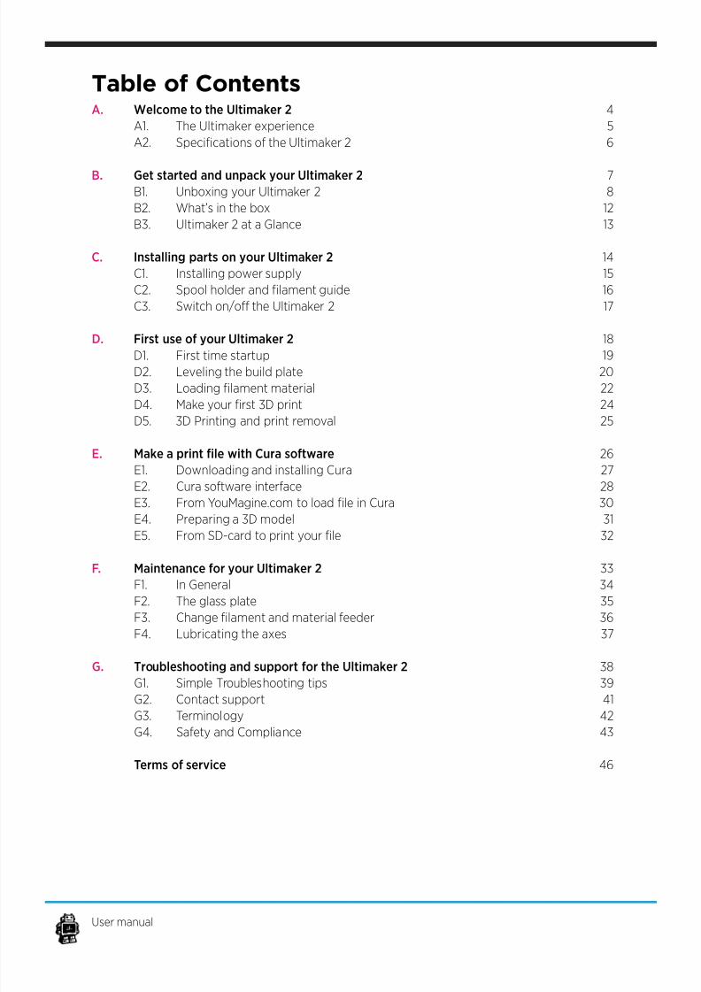
Table of ContentsA. Welcome to the Ultimaker 2
A1. The Ultimaker experience
A2. Specications of the Ultimaker 2
B. Get started and unpack your Ultimaker 2 B1. Unboxing your Ultimaker 2
B2. What’s in the box
B3. Ultimaker 2 at a Glance
C. Installing parts on your Ultimaker 2
C1. Installing power supply
C2. Spool holder and lament guide
C3. Switch on/o the Ultimaker 2
D. First use of your Ultimaker 2
D1. First time startup
D2. Leveling the build plate
D3. Loading lament material
D4. Make your rst 3D print
D5. 3D Printing and print removal
E. Make a print le with Cura software
E1. Downloading and installing Cura
E2. Cura software interface
E3. From YouMagine.com to load le in Cura
E4. Preparing a 3D model E5. From SD-card to print your le
F. Maintenance for your Ultimaker 2
F1. In General
F2. The glass plate
F3. Change lament and material feeder
F4. Lubricating the axes
G. Troubleshooting and support for the Ultimaker 2
G1. Simple Troubleshooting tips
G2. Contact support G3. Terminology
G4. Safety and Compliance
Terms of service
4
5
6
78
12
13
14
15
16
17
18
19
20
22
24
25
26
27
28
30
3132
33
34
35
36
37
38
39
41
42
43
46
User manual

7/17/2019 Ultimaker 2 - User Manual v1.13
http://slidepdf.com/reader/full/ultimaker-2-user-manual-v113 4/50
WELCOMETO THE
ULTIMAKER 2
4
7/17/2019 Ultimaker 2 - User Manual v1.13
http://slidepdf.com/reader/full/ultimaker-2-user-manual-v113 5/50
This User manual is designed to help you start your
experience with Ultimaker 2. Within these pages, we
want to show you how simple and easy it is to pro-duce great prints.
You might be familiar with earlier types of Ultimakers
or other 3D-printers. It is essential that your read this
manual carefully as there are a lot of new procedures
with Ultimaker 2.
For a more personal guidance towards your
Ultimaker 2 you can also watch the “Unboxing” and
”First time startup” video’s under the following links:http://vimeo.com/ultimaker/ 2-unboxing http://vimeo.com/ultimaker/ 2-frsttimestartup
A1. The Ultimaker Experience
A. Welcome to the Ultimaker 2 5
7/17/2019 Ultimaker 2 - User Manual v1.13
http://slidepdf.com/reader/full/ultimaker-2-user-manual-v113 6/50
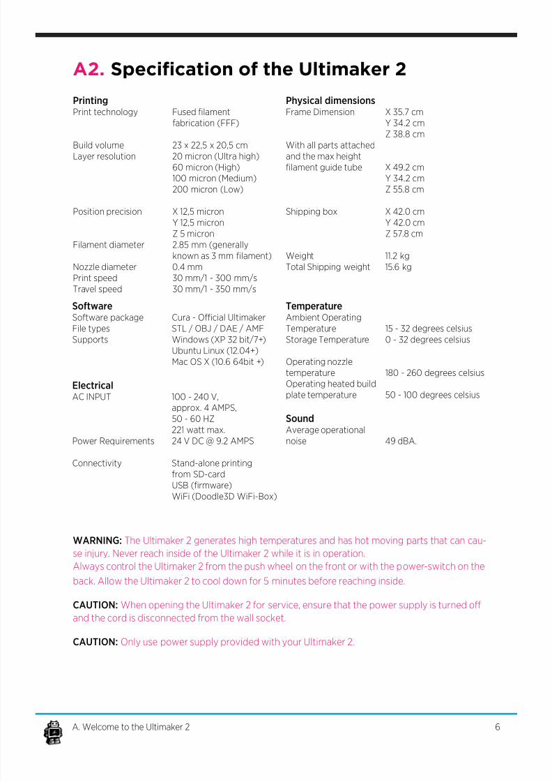
A2. Specication of the Ultimaker 2
PrintingPrint technology Fused lament
fabrication (FFF)
Build volume 23 x 22,5 x 20,5 cm
Layer resolution 20 micron (Ultra high)
60 micron (High)
100 micron (Medium)
200 micron (Low)
Position precision X 12,5 micron
Y 12,5 micron
Z 5 micron
Filament diameter 2.85 mm (generally
known as 3 mm lament)
Nozzle diameter 0.4 mm
Print speed 30 mm/1 - 300 mm/sTravel speed 30 mm/1 - 350 mm/s
SoftwareSoftware package Cura - Ocial Ultimaker
File types STL / OBJ / DAE / AMF
Supports Windows (XP 32 bit/7+)
Ubuntu Linux (12.04+)
Mac OS X (10.6 64bit +)
ElectricalAC INPUT 100 - 240 V,
approx. 4 AMPS,50 - 60 HZ
221 watt max.
Power Requirements 24 V DC @ 9.2 AMPS
Connectivity Stand-alone printing
from SD-card
USB (rmware)
WiFi (Doodle3D WiFi-Box)
WARNING: The Ultimaker 2 generates high temperatures and has hot moving parts that can cau-
se injury. Never reach inside of the Ultimaker 2 while it is in operation.
Always control the Ultimaker 2 from the push wheel on the front or with the power-switch on the
back. Allow the Ultimaker 2 to cool down for 5 minutes before reaching inside.
CAUTION: When opening the Ultimaker 2 for service, ensure that the power supply is turned o
and the cord is disconnected from the wall socket.
CAUTION: Only use power supply provided with your Ultimaker 2.
6A. Welcome to the Ultimaker 2
Physical dimensionsFrame Dimension X 35.7 cm
Y 34.2 cm
Z 38.8 cmWith all parts attached
and the max height
lament guide tube X 49.2 cm
Y 34.2 cm
Z 55.8 cm
Shipping box X 42.0 cm
Y 42.0 cm
Z 57.8 cm
Weight 11.2 kg
Total Shipping weight 15.6 kg
TemperatureAmbient Operating
Temperature 15 - 32 degrees celsius
Storage Temperature 0 - 32 degrees celsius
Operating nozzle
temperature 180 - 260 degrees celsius
Operating heated build
plate temperature 50 - 100 degrees celsius
SoundAverage operational
noise 49 dBA.

7/17/2019 Ultimaker 2 - User Manual v1.13
http://slidepdf.com/reader/full/ultimaker-2-user-manual-v113 7/50
GET STARTED &
UNPACK YOUR
ULTIMAKER 2
7
7/17/2019 Ultimaker 2 - User Manual v1.13
http://slidepdf.com/reader/full/ultimaker-2-user-manual-v113 8/50
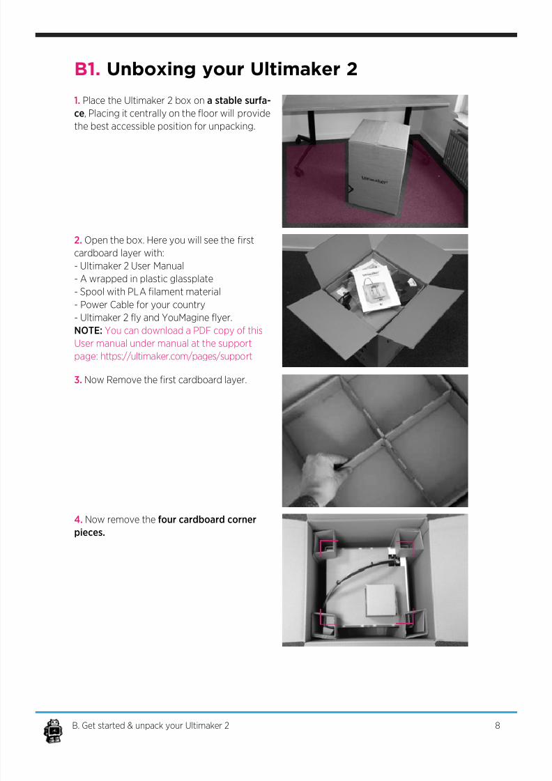
B1. Unboxing your Ultimaker 2
1. Place the Ultimaker 2 box on a stable surfa-
ce, Placing it centrally on the oor will provide
the best accessible position for unpacking.
2. Open the box. Here you will see the rst
cardboard layer with:
- Ultimaker 2 User Manual
- A wrapped in plastic glassplate
- Spool with PLA lament material
- Power Cable for your country
- Ultimaker 2 y and YouMagine yer.
NOTE: You can download a PDF copy of this
User manual under manual at the support
page: h t t p s : / / u l t i m a k e r . c o m / p a g e s / s u p p o r t
3. Now Remove the rst cardboard layer.
4. Now remove the four cardboard corner
pieces.
8B. Get started & unpack your Ultimaker 2
7/17/2019 Ultimaker 2 - User Manual v1.13
http://slidepdf.com/reader/full/ultimaker-2-user-manual-v113 9/50
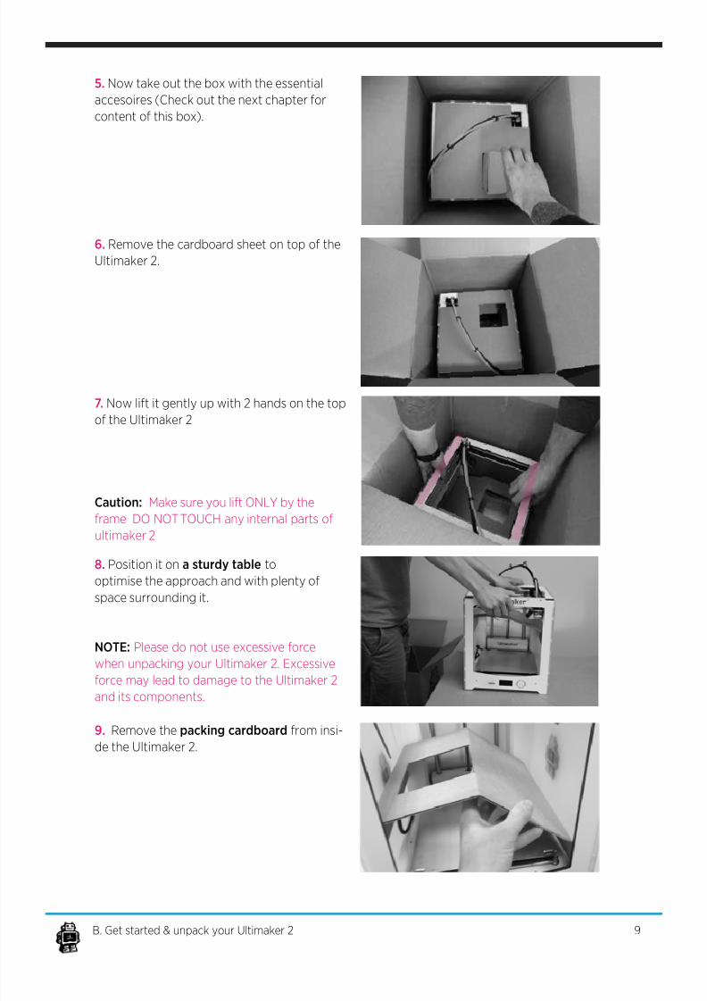
5. Now take out the box with the essential
accesoires (Check out the next chapter for
content of this box).
6. Remove the cardboard sheet on top of the
Ultimaker 2.
7. Now lift it gently up with 2 hands on the top
of the Ultimaker 2
Caution: Make sure you lift ONLY by the
frame DO NOT TOUCH any internal parts of
ultimaker 2
8. Position it on a sturdy table to
optimise the approach and with plenty of
space surrounding it.
NOTE: Please do not use excessive force
when unpacking your Ultimaker 2. Excessive
force may lead to damage to the Ultimaker 2
and its components.
9B. Get started & unpack your Ultimaker 2
9. Remove the packing cardboard from insi-
de the Ultimaker 2.
7/17/2019 Ultimaker 2 - User Manual v1.13
http://slidepdf.com/reader/full/ultimaker-2-user-manual-v113 10/50
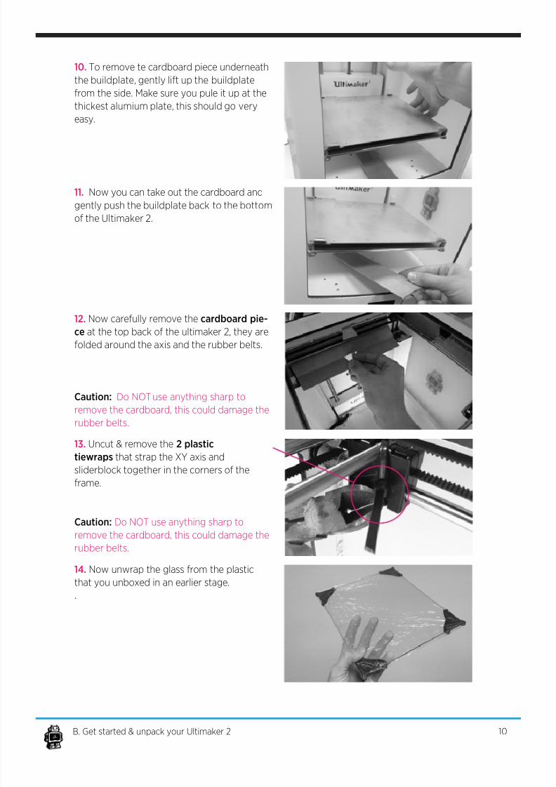
10. To remove te cardboard piece underneath
the buildplate, gently lift up the buildplate
from the side. Make sure you pule it up at the
thickest alumium plate, this should go very
easy.
11. Now you can take out the cardboard and
gently push the buildplate back to the bottom
of the Ultimaker 2.
12. Now carefully remove the cardboard pie-
ce at the top back of the ultimaker 2, they are
folded around the axis and the rubber belts.
Caution: Do NOT use anything sharp to
remove the cardboard, this could damage therubber belts.
13. Uncut & remove the 2 plastic
tiewraps that strap the XY axis and
sliderblock together in the corners of the
frame.
Caution: Do NOT use anything sharp to
remove the cardboard, this could damage the
rubber belts.
10B. Get started & unpack your Ultimaker 2
14. Now unwrap the glass from the plastic
that you unboxed in an earlier stage.
.
7/17/2019 Ultimaker 2 - User Manual v1.13
http://slidepdf.com/reader/full/ultimaker-2-user-manual-v113 11/50
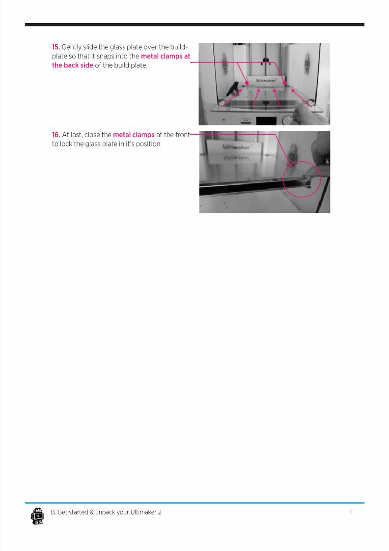
15. Gently slide the glass plate over the build-
plate so that it snaps into the metal clamps at
the back side of the build plate.
16. At last, close the metal clamps at the front
to lock the glass plate in it’s position.
11B. Get started & unpack your Ultimaker 2
7/17/2019 Ultimaker 2 - User Manual v1.13
http://slidepdf.com/reader/full/ultimaker-2-user-manual-v113 12/50
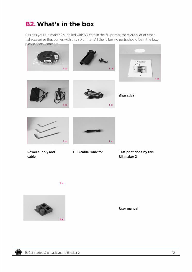
B2. What’s in the box
Spool holder & lamentguide
Filament spool
USB cable (only for
rmware update)
Glue stick
Hex wrenches Grease User manual
Power supply and
cable
Test print done by this
Ultimaker 2
Besides your Ultimaker 2 supplied with SD card in the 3D printer, there are a lot of essen-
tial accesoires that comes with this 3D printer. All the following parts should be in the box,
please check contents.
12B. Get started & unpack your Ultimaker 2
7/17/2019 Ultimaker 2 - User Manual v1.13
http://slidepdf.com/reader/full/ultimaker-2-user-manual-v113 13/50
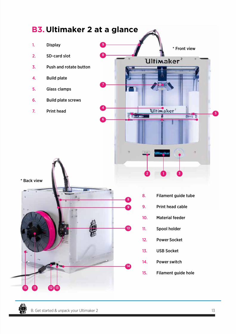
B3. Ultimaker 2 at a glance
* Front view
* Back view
13B. Get started & unpack your Ultimaker 2
1. Display
2. SD-card slot
3. Push and rotate button
4. Build plate
5. Glass clamps
6. Build plate screws
7. Print head
8. Filament guide tube
9. Print head cable
10. Material feeder
11. Spool holder
12. Power Socket
13. USB Socket
14. Power switch
15. Filament guide hole
7/17/2019 Ultimaker 2 - User Manual v1.13
http://slidepdf.com/reader/full/ultimaker-2-user-manual-v113 14/50
INSTALLING
PARTS
ON YOUR
ULTIMAKER 2
14
7/17/2019 Ultimaker 2 - User Manual v1.13
http://slidepdf.com/reader/full/ultimaker-2-user-manual-v113 15/50
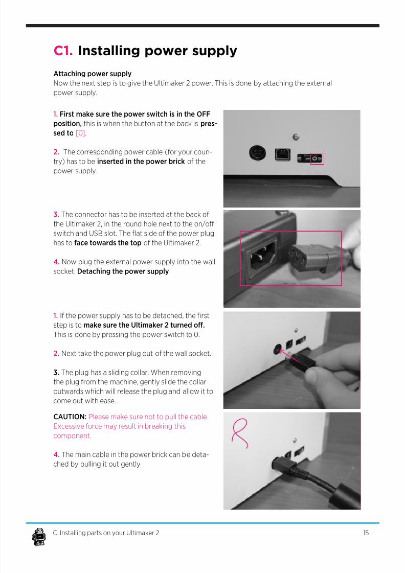
C1. Installing power supply
Attaching power supply
Now the next step is to give the Ultimaker 2 power. This is done by attaching the external
power supply.
3. The connector has to be inserted at the back of
the Ultimaker 2, in the round hole next to the on/o
switch and USB slot. The at side of the power plug
has to face towards the top of the Ultimaker 2.
4. Now plug the external power supply into the wall
socket. Detaching the power supply
1. First make sure the power switch is in the OFF
position, this is when the button at the back is pres-
sed to [0].
2. The corresponding power cable (for your coun-
try) has to be inserted in the power brick of the
power supply.
15C. Installing parts on your Ultimaker 2
1. If the power supply has to be detached, the rst
step is to make sure the Ultimaker 2 turned o.
This is done by pressing the power switch to 0.
2. Next take the power plug out of the wall socket.
3. The plug has a sliding collar. When removing
the plug from the machine, gently slide the collar
outwards which will release the plug and allow it to
come out with ease.
CAUTION: Please make sure not to pull the cable.
Excessive force may result in breaking this
component.
4. The main cable in the power brick can be deta-
ched by pulling it out gently.
7/17/2019 Ultimaker 2 - User Manual v1.13
http://slidepdf.com/reader/full/ultimaker-2-user-manual-v113 16/50
C2. Spool holder and lament guide
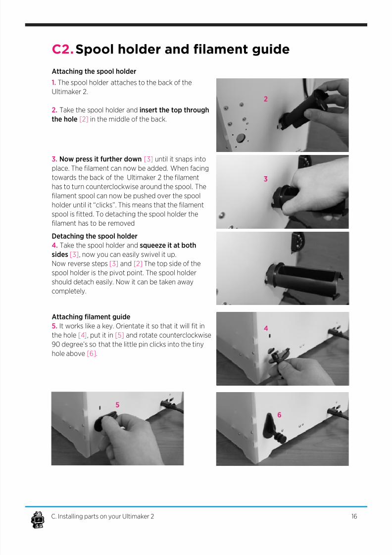
Attaching the spool holder
1. The spool holder attaches to the back of the
Ultimaker 2.
2. Take the spool holder and insert the top through
the hole [2] in the middle of the back.
3. Now press it further down [3] until it snaps into
place. The lament can now be added. When facing
towards the back of the Ultimaker 2 the lament
has to turn counterclockwise around the spool. The
lament spool can now be pushed over the spoolholder until it “clicks”. This means that the lament
spool is tted. To detaching the spool holder the
lament has to be removed
Detaching the spool holder
4. Take the spool holder and squeeze it at both
sides [3], now you can easily swivel it up.
Now reverse steps [3] and [2] The top side of the
spool holder is the pivot point. The spool holder
should detach easily. Now it can be taken away
completely.
Attaching lament guide
5. It works like a key. Orientate it so that it will t in
the hole [4], put it in [5] and rotate counterclockwise
90 degree’s so that the little pin clicks into the tiny
hole above [6].
16C. Installing parts on your Ultimaker 2
7/17/2019 Ultimaker 2 - User Manual v1.13
http://slidepdf.com/reader/full/ultimaker-2-user-manual-v113 17/50
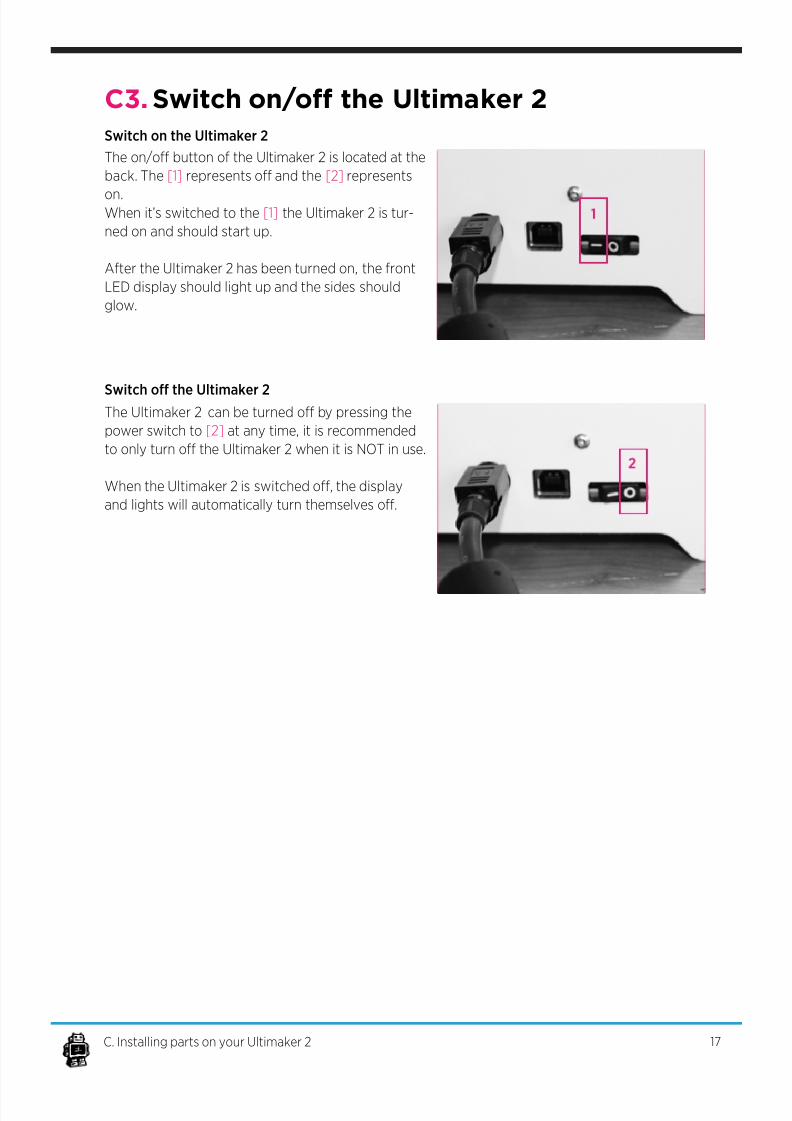
C3. Switch on/o the Ultimaker 2
Switch on the Ultimaker 2
The Ultimaker 2 can be turned o by pressing the
power switch to [2] at any time, it is recommended
to only turn o the Ultimaker 2 when it is NOT in use.
When the Ultimaker 2 is switched o, the display
and lights will automatically turn themselves o.
The on/o button of the Ultimaker 2 is located at the
back. The [1] represents o and the [2] represents
on.When it’s switched to the [1] the Ultimaker 2 is tur-
ned on and should start up.
After the Ultimaker 2 has been turned on, the front
LED display should light up and the sides should
glow.
Switch o the Ultimaker 2
17C. Installing parts on your Ultimaker 2

7/17/2019 Ultimaker 2 - User Manual v1.13
http://slidepdf.com/reader/full/ultimaker-2-user-manual-v113 18/50
FIRST USE
OF YOUR
ULTIMAKER 2
18
7/17/2019 Ultimaker 2 - User Manual v1.13
http://slidepdf.com/reader/full/ultimaker-2-user-manual-v113 19/50
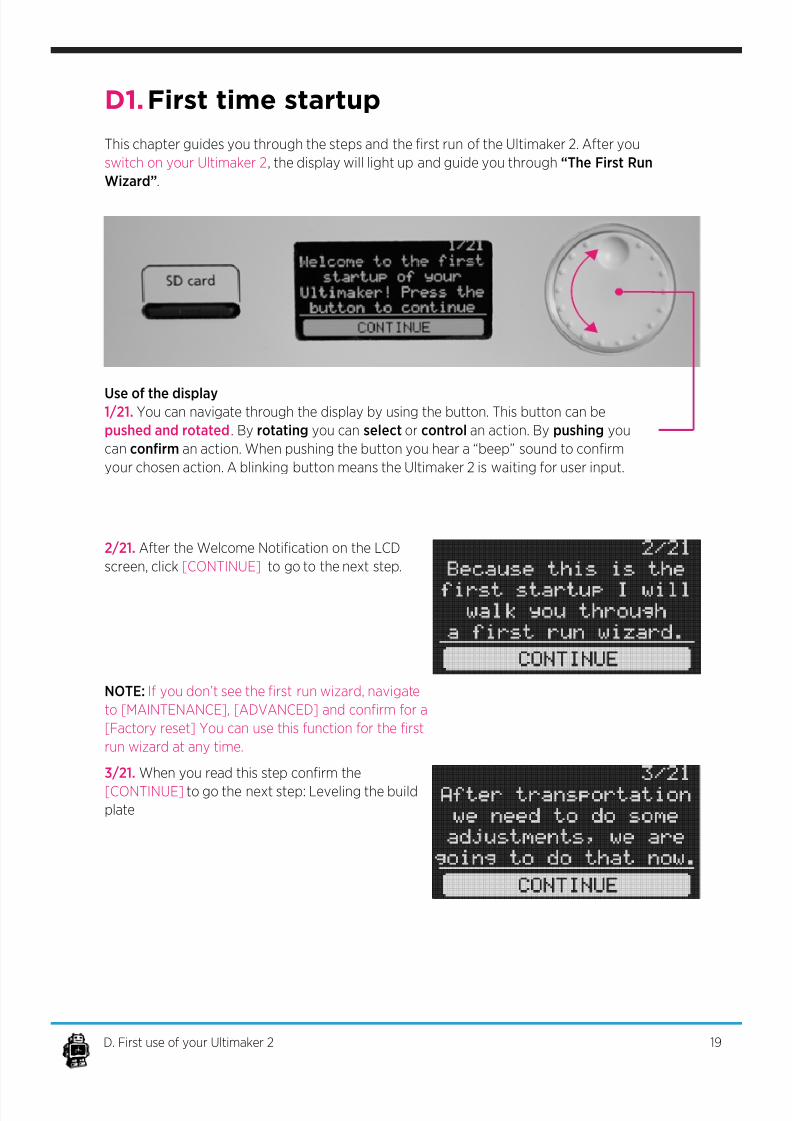
D1. First time startup
2/21. After the Welcome Notication on the LCD
screen, click [CONTINUE] to go to the next step.
3/21. When you read this step conrm the
[CONTINUE] to go the next step: Leveling the build
plate
NOTE: If you don’t see the rst run wizard, navigate
to [MAINTENANCE], [ADVANCED] and conrm for a
[Factory reset] You can use this function for the rst
run wizard at any time.
This chapter guides you through the steps and the rst run of the Ultimaker 2. After you
switch on your Ultimaker 2, the display will light up and guide you through “The First Run
Wizard”.
Use of the display1/21. You can navigate through the display by using the button. This button can be
pushed and rotated. By rotating you can select or control an action. By pushing you
can conrm an action. When pushing the button you hear a “beep” sound to conrm
your chosen action. A blinking button means the Ultimaker 2 is waiting for user input.
19D. First use of your Ultimaker 2
7/17/2019 Ultimaker 2 - User Manual v1.13
http://slidepdf.com/reader/full/ultimaker-2-user-manual-v113 20/50
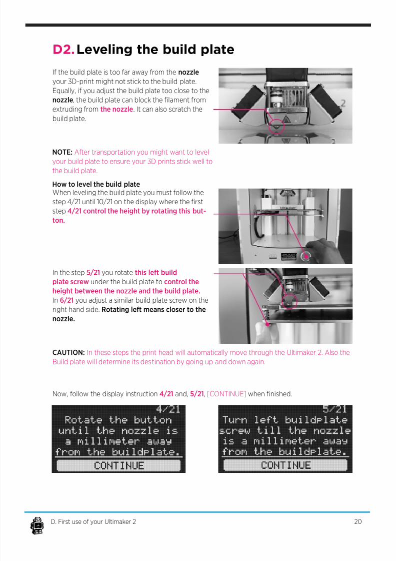
If the build plate is too far away from the nozzle
your 3D-print might not stick to the build plate.
Equally, if you adjust the build plate too close to the
nozzle, the build plate can block the lament fromextruding from the nozzle. It can also scratch the
build plate.
When leveling the build plate you must follow the
step 4/21 until 10/21 on the display where the rst
step 4/21 control the height by rotating this but-
ton.
In the step 5/21 you rotate this left build
plate screw under the build plate to control the
height between the nozzle and the build plate.
In 6/21 you adjust a similar build plate screw on the
right hand side. Rotating left means closer to the
nozzle.
Now, follow the display instruction 4/21 and, 5/21, [CONTINUE] when nished.
How to level the build plate
NOTE: After transportation you might want to level
your build plate to ensure your 3D prints stick well to
the build plate.
CAUTION: In these steps the print head will automatically move through the Ultimaker 2. Also the
Build plate will determine its destination by going up and down again.
D2. Leveling the build plate
20D. First use of your Ultimaker 2
7/17/2019 Ultimaker 2 - User Manual v1.13
http://slidepdf.com/reader/full/ultimaker-2-user-manual-v113 21/50
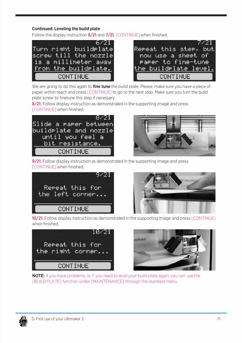
Continued: Leveling the build plate
Follow the display instruction 6/21 and 7/21, [CONTINUE] when nished.
We are going to do this again to ne tune the build plate. Please, make sure you have a piece of
paper within reach and press [CONTINUE] to go to the next step. Make sure you turn the build
plate screw to netune this step if necessary.
8/21. Follow display instruction as demonstrated in the supporting image and press
[CONTINUE] when nished.
9/21. Follow display instruction as demonstrated in the supporting image and press
[CONTINUE] when nished.
10/21. Follow display instruction as demonstrated in the supporting image and press [CONTINUE]
when nished.
NOTE: If you have problems, or if you need to level your build plate again, you can use the
[BUILD PLATE] function under [MAINTENANCE] through the standard menu.
21D. First use of your Ultimaker 2
7/17/2019 Ultimaker 2 - User Manual v1.13
http://slidepdf.com/reader/full/ultimaker-2-user-manual-v113 22/50
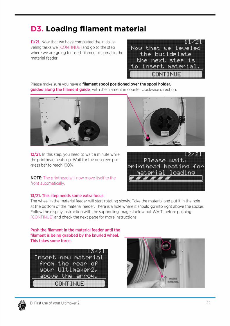
12/21. In this step, you need to wait a minute while
the printhead heats up. Wait for the onscreen pro-
gress bar to reach 100%
Please make sure you have a lament spool positioned over the spool holder,
guided along the lament guide, with the lament in counter clockwise direction.
13/21. This step needs some extra focus.
The wheel in the material feeder will start rotating slowly. Take the material and put it in the hole
at the bottom of the material feeder. There is a hole where it should go into right above the sticker.
Follow the display instruction with the supporting images below but WAIT! before pushing
[CONTINUE] and check the next page for more instructions.
11/21. Now that we have completed the initial le-
veling tasks we [CONTINUE] and go to the step
where we are going to insert lament material in the
material feeder.
NOTE: The printhead will now move itself to the
front automatically.
Push the lament in the material feeder until thelament is being grabbed by the knurled wheel.
This takes some force.
D3. Loading lament material
22D. First use of your Ultimaker 2
7/17/2019 Ultimaker 2 - User Manual v1.13
http://slidepdf.com/reader/full/ultimaker-2-user-manual-v113 23/50
You can [CONTINUE] this step, 13/21, when the
material is loaded until it reaches the rst
bowden tube clip.
14/21. The lament is being pulled through the
transparent bowden-tube more quickly. Wait until
the progress bar is full.
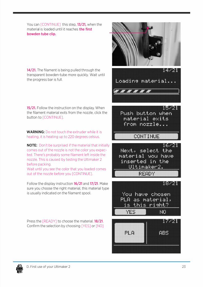
15/21. Follow the instruction on the display. When
the lament material exits from the nozzle, click the
button to [CONTINUE].
Follow the display instruction 16/21 and 17/21. Make
sure you choose the right material, this material type
is usually indicated on the lament spool.
Press the [READY] to choose the material. 18/21.
Conrm the selection by choosing [YES] or [NO]
WARNING: Do not touch the extruder while it is
heating, it is heating up to 220 degrees celsius.
NOTE: Don’t be surprised if the material that initially
comes out of the nozzle is not the color you expec-ted. There’s probably some lament left inside the
nozzle. This is caused by testing the Ultimaker 2
before packing.
Wait until you see the color that you loaded comes
out of the nozzle before you [CONTINUE].
23D. First use of your Ultimaker 2
7/17/2019 Ultimaker 2 - User Manual v1.13
http://slidepdf.com/reader/full/ultimaker-2-user-manual-v113 24/50
D4. Make your rst 3D print
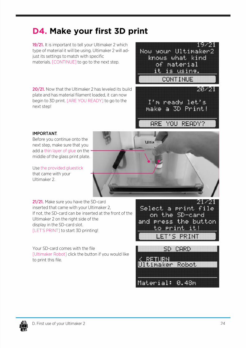
19/21. It is important to tell your Ultimaker 2 which
type of material it will be using. Ultimaker 2 will ad-
just its settings to match with specic
materials. [CONTINUE] to go to the next step.
20/21. Now that the Ultimaker 2 has leveled its build
plate and has material lament loaded, it can now
begin to 3D print. [ARE YOU READY] to go to the
next step!
21/21. Make sure you have the SD-card
inserted that came with your Ultimaker 2,
If not, the SD-card can be inserted at the front of the
Ultimaker 2 on the right side of the
display in the SD-card slot.
[LET’S PRINT] to start 3D printing!
Your SD-card comes with the le
[Ultimaker Robot] click the button if you would like
to print this le.
IMPORTANT.
Before you continue onto the
next step, make sure that you
add a thin layer of glue on the
middle of the glass print plate.
Use the provided gluestick
that came with your
Ultimaker 2.
24D. First use of your Ultimaker 2
7/17/2019 Ultimaker 2 - User Manual v1.13
http://slidepdf.com/reader/full/ultimaker-2-user-manual-v113 25/50
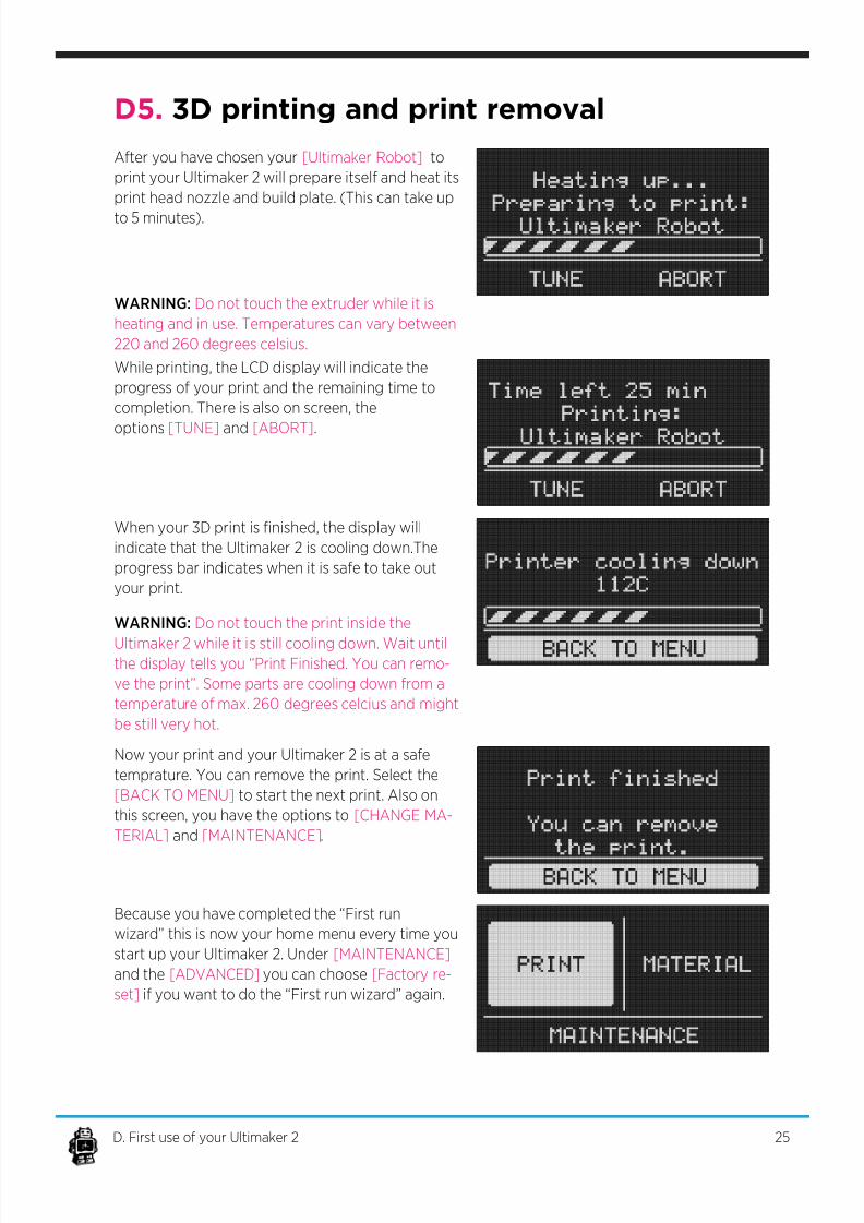
While printing, the LCD display will indicate the
progress of your print and the remaining time to
completion. There is also on screen, the
options [TUNE] and [ABORT].
When your 3D print is nished, the display will
indicate that the Ultimaker 2 is cooling down.The
progress bar indicates when it is safe to take out
your print.
Now your print and your Ultimaker 2 is at a safe
temprature. You can remove the print. Select the
[BACK TO MENU] to start the next print. Also on
this screen, you have the options to [CHANGE MA-
TERIAL] and [MAINTENANCE].
Because you have completed the “First run
wizard” this is now your home menu every time you
start up your Ultimaker 2. Under [MAINTENANCE]
and the [ADVANCED] you can choose [Factory re-
set] if you want to do the “First run wizard” again.
WARNING: Do not touch the print inside the
Ultimaker 2 while it is still cooling down. Wait untilthe display tells you “Print Finished. You can remo-
ve the print”. Some parts are cooling down from a
temperature of max. 260 degrees celcius and might
be still very hot.
After you have chosen your [Ultimaker Robot] to
print your Ultimaker 2 will prepare itself and heat its
print head nozzle and build plate. (This can take up
to 5 minutes).
WARNING: Do not touch the extruder while it is
heating and in use. Temperatures can vary between
220 and 260 degrees celsius.
D5. 3D printing and print removal
25D. First use of your Ultimaker 2
7/17/2019 Ultimaker 2 - User Manual v1.13
http://slidepdf.com/reader/full/ultimaker-2-user-manual-v113 26/50
MAKE A
PRINTFILE WITH
CURA SOFTWARE
26
7/17/2019 Ultimaker 2 - User Manual v1.13
http://slidepdf.com/reader/full/ultimaker-2-user-manual-v113 27/50
E1. Downloading and installing Cura
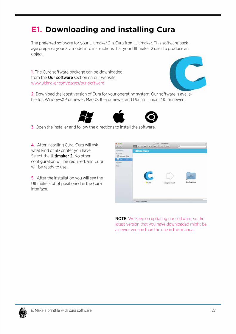
The preferred software for your Ultimaker 2 is Cura from Ultimaker. This software pack-
age prepares your 3D model into instructions that your Ultimaker 2 uses to produce an
object.
1. The Cura software package can be downloaded
from the Our software section on our website:
w w w . u l t i m a k e r . c o m /pages/our-software
2. Download the latest version of Cura for your operating system. Our software is availa-
ble for, WindowsXP or newer, MacOS 10.6 or newer and Ubuntu Linux 12.10 or newer.
3. Open the installer and follow the directions to install the software.
4. After installing Cura, Cura will ask
what kind of 3D printer you have.
Select the Ultimaker 2. No other
conguration will be required, and Cura
will be ready to use.
5. After the installation you will see the
Ultimaker-robot positioned in the Cura
interface.
NOTE: We keep on updating our software, so the
latest version that you have downloaded might be
a newer version than the one in this manual.
27E. Make a printle with cura software
7/17/2019 Ultimaker 2 - User Manual v1.13
http://slidepdf.com/reader/full/ultimaker-2-user-manual-v113 28/50
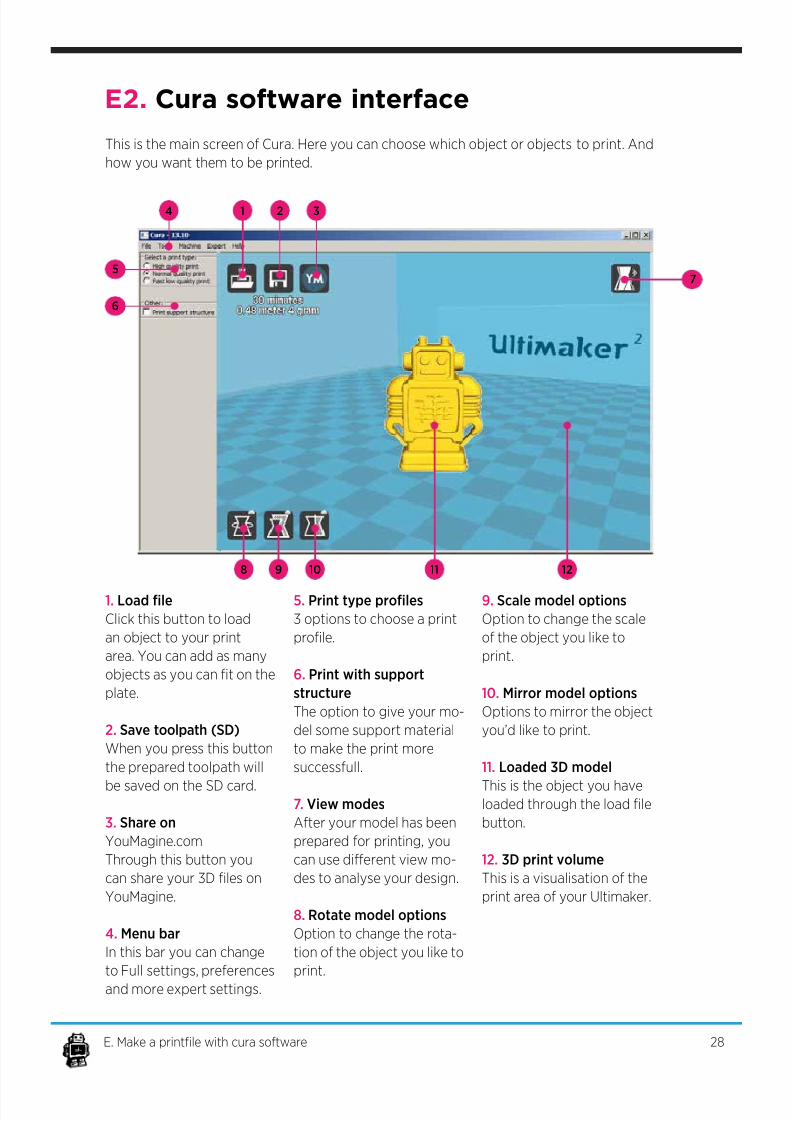
This is the main screen of Cura. Here you can choose which object or objects to print. And
how you want them to be printed.
1. Load le
Click this button to load
an object to your print
area. You can add as many
objects as you can t on the
plate.
2. Save toolpath (SD)
When you press this button
the prepared toolpath will
be saved on the SD card.
3. Share on
YouMagine.com
Through this button you
can share your 3D les on
YouMagine.
4. Menu bar
In this bar you can change
to Full settings, preferences
and more expert settings.
5. Print type proles
3 options to choose a print
prole.
6. Print with support
structure
The option to give your mo-
del some support material
to make the print more
successfull.
7. View modes
After your model has been
prepared for printing, you
can use dierent view mo-
des to analyse your design.
8. Rotate model options
Option to change the rota-
tion of the object you like to
print.
9. Scale model options
Option to change the scale
of the object you like to
print.
10. Mirror model options
Options to mirror the object
you’d like to print.
11. Loaded 3D model
This is the object you haveloaded through the load le
button.
12. 3D print volume
This is a visualisation of the
print area of your Ultimaker.
14 2 3
5
6
7
8 9 10 11 12
E2. Cura software interface
28E. Make a printle with cura software
7/17/2019 Ultimaker 2 - User Manual v1.13
http://slidepdf.com/reader/full/ultimaker-2-user-manual-v113 29/50
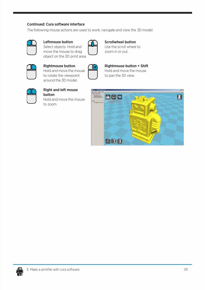
Continued: Cura software interface
The following mouse actions are used to work, navigate and view the 3D model:
Leftmouse button
Select objects. Hold and
move the mouse to dragobject on the 3D print area.
Rightmouse button
Hold and move the mouse
to rotate the viewpoint
around the 3D model.
Right and left mouse
button
Hold and move the mouse
to zoom.
Scrollwheel button
Use the scroll wheel to
zoom in or out.
Rightmouse button + Shift
Hold and move the mouse
to pan the 3D view.
29E. Make a printle with cura software
7/17/2019 Ultimaker 2 - User Manual v1.13
http://slidepdf.com/reader/full/ultimaker-2-user-manual-v113 30/50
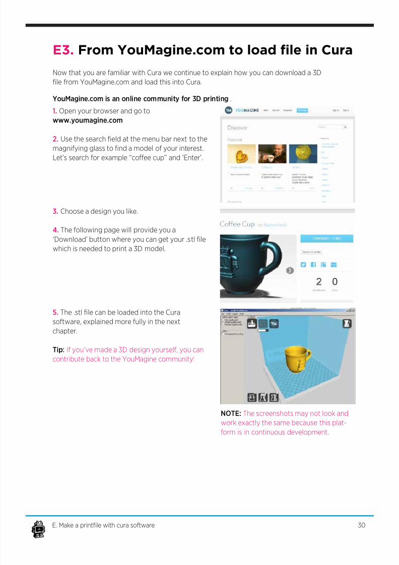
E3. From YouMagine.com to load le in Cura
Y o u M a g i n e . c o m is an online community for 3D printing.
1. Open your browser and go to
www.youmagine.com
2. Use the search eld at the menu bar next to the
magnifying glass to nd a model of your interest.
Let’s search for example “coee cup” and ‘Enter’.
3. Choose a design you like.
4. The following page will provide you a
‘Download’ button where you can get your .stl le
which is needed to print a 3D model.
5. The .stl le can be loaded into the Cura
software, explained more fully in the next
chapter.
Tip: If you’ve made a 3D design yourself, you can
contribute back to the YouMagine community!
Now that you are familiar with Cura we continue to explain how you can download a 3D
le from YouMagine.com and load this into Cura.
NOTE: The screenshots may not look and
work exactly the same because this plat-
form is in continuous development.
30E. Make a printle with cura software
7/17/2019 Ultimaker 2 - User Manual v1.13
http://slidepdf.com/reader/full/ultimaker-2-user-manual-v113 31/50
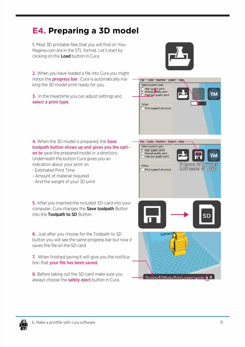
E4. Preparing a 3D model
1. Most 3D printable les that you will nd on You-
Magine.com are in the STL format. Let’s start by
clicking on the Load button in Cura.
2. When you have loaded a le into Cura you might
notice the progress bar. Cura is automatically ma-
king the 3D model print ready for you.
3. In the meantime you can adjust settings and
select a print type.
4. When the 3D model is prepared, the Save
toolpath button shows up and gives you the opti-
on to save the prepared model in a directory.
Underneath the button Cura gives you an
indication about your print on
- Estimated Print Time
- Amount of material required
- And the weight of your 3D print
5. After you inserted the included SD-card into your
computer, Cura changes the Save toolpath Button
into the Toolpath to SD Button.
6. Just after you choose for the Toolpath to SD
button you will see the same progress bar but now it
saves the le on the SD card.
7. When nished saving It will give you the notica-
tion that your le has been saved.
8. Before taking out the SD-card make sure you
always choose the safely eject button in Cura.
31E. Make a printle with cura software
7/17/2019 Ultimaker 2 - User Manual v1.13
http://slidepdf.com/reader/full/ultimaker-2-user-manual-v113 32/50
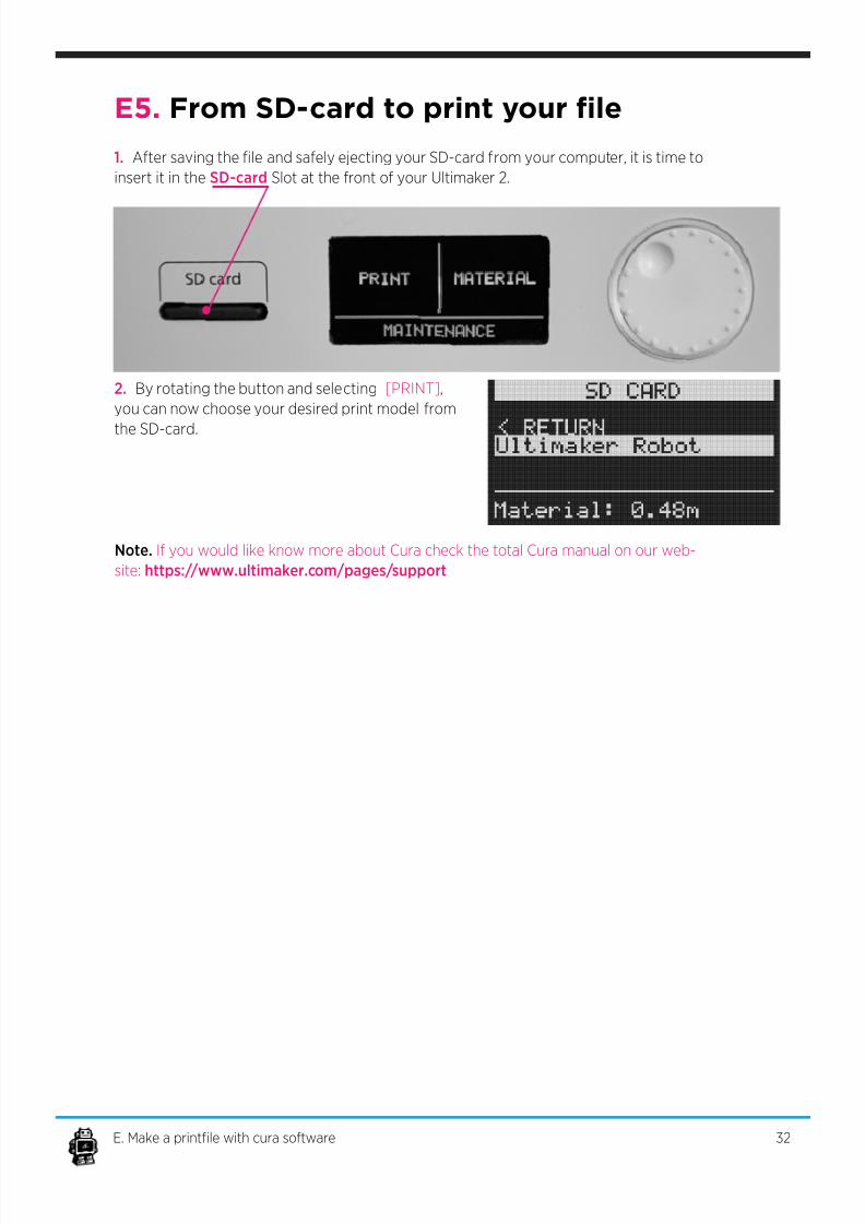
E5. From SD-card to print your le
1. After saving the le and safely ejecting your SD-card from your computer, it is time to
insert it in the SD-card Slot at the front of your Ultimaker 2.
2. By rotating the button and selecting [PRINT],
you can now choose your desired print model from
the SD-card.
32E. Make a printle with cura software
Note. If you would like know more about Cura check the total Cura manual on our web-
site: https://www.ultimaker.com/pages/support

7/17/2019 Ultimaker 2 - User Manual v1.13
http://slidepdf.com/reader/full/ultimaker-2-user-manual-v113 33/50
MAINTENANCE
FOR YOUR ULTIMAKER 2
33

7/17/2019 Ultimaker 2 - User Manual v1.13
http://slidepdf.com/reader/full/ultimaker-2-user-manual-v113 34/50
F1. In General
To achieve the best possible results from your Ultimaker 2, some basic annual mainte-
nance is recommended. This chapter contains tips which helps you to keep the Ultimaker
2 running at it’s best.
Before you make a print a quick check is advised. A visual check is
recommended to see if there is not any:
- old prints/objects on the build plate.
- make sure no one can possibly walk over, damage or pull out the power supply cable.
Updating rmware with USB cable
Once a while Cura will give you a mention that new rmware available. New rmware
means that we have optimize the control of the electronics which will gives better print
results and user experience. If you see this mention, connect the USB cable between your
computer and your Ultimaker 2 and follow the instructions in Cura.
34F. Maintenance for your Ultimaker 2
7/17/2019 Ultimaker 2 - User Manual v1.13
http://slidepdf.com/reader/full/ultimaker-2-user-manual-v113 35/50
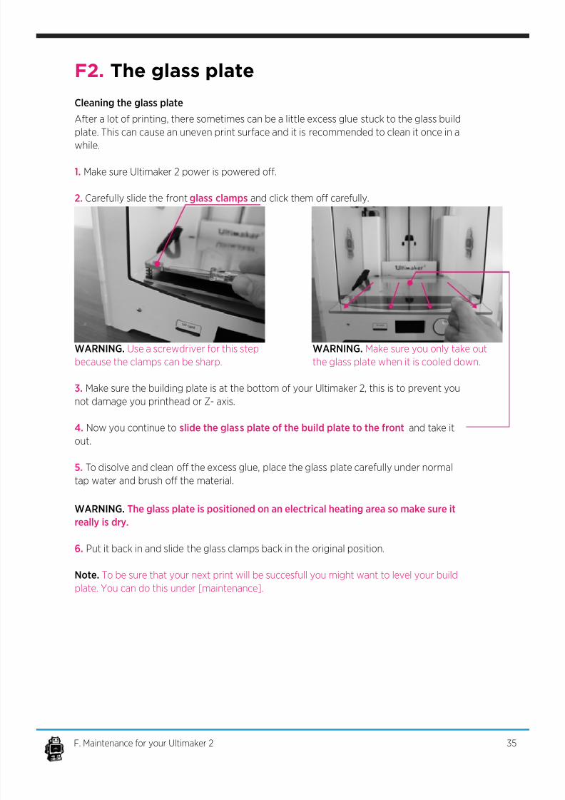
F2. The glass plate
After a lot of printing, there sometimes can be a little excess glue stuck to the glass build
plate. This can cause an uneven print surface and it is recommended to clean it once in a
while.
1. Make sure Ultimaker 2 power is powered o.
2. Carefully slide the front glass clamps and click them o carefully.
3. Make sure the building plate is at the bottom of your Ultimaker 2, this is to prevent you
not damage you printhead or Z- axis.
4. Now you continue to slide the glass plate of the build plate to the front and take it
out.
5. To disolve and clean o the excess glue, place the glass plate carefully under normal
tap water and brush o the material.
WARNING. The glass plate is positioned on an electrical heating area so make sure it
really is dry.
6. Put it back in and slide the glass clamps back in the original position.
Note. To be sure that your next print will be succesfull you might want to level your build
plate. You can do this under [maintenance].
WARNING. Use a screwdriver for this step
because the clamps can be sharp.
WARNING. Make sure you only take out
the glass plate when it is cooled down.
Cleaning the glass plate
35F. Maintenance for your Ultimaker 2
7/17/2019 Ultimaker 2 - User Manual v1.13
http://slidepdf.com/reader/full/ultimaker-2-user-manual-v113 36/50
F3. Change lament and material feeder
Removing lament
Feeding material
Clean material feeder
In the Ultimaker 2 the lament material can be changed. As you have learned in previous
steps there is no need to do this all by yourself because the Ultimaker 2 helps you with
that.
1. Go to the [MATERIAL] tab on the main menu of the display. Press the button: next go
to [CHANGE], this can be done by turning the wheel next to the screen. Press the button.
Note: rmware updates in the future may use a dierent terminology.
2. Your Ultimaker 2 will heat up so the material can be removed later. When the required
temperature is met, the feeder will turn by itself and retract the lament.
3. Rewind the lament on the lament spool and make sure it cannot uncoil at a later
moment (secure with hole in spool, tape or anything that works).
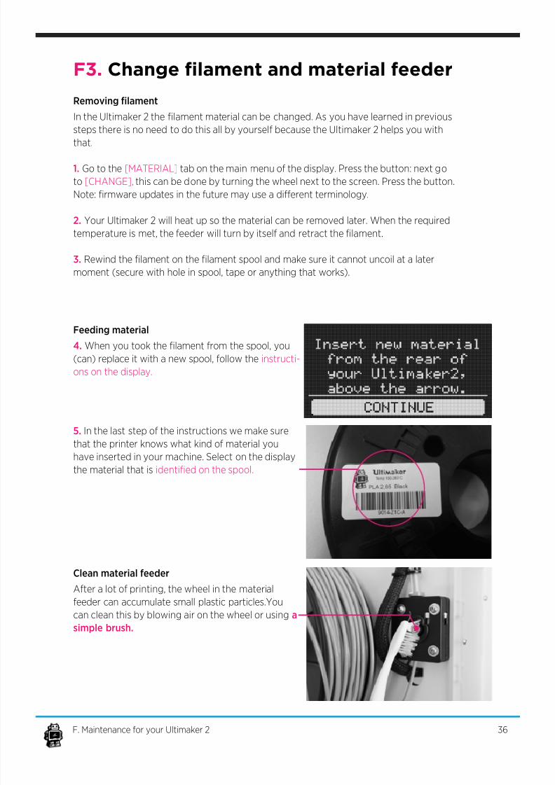
4. When you took the lament from the spool, you
(can) replace it with a new spool, follow the instructi-
ons on the display.
5. In the last step of the instructions we make sure
that the printer knows what kind of material you
have inserted in your machine. Select on the display
the material that is identied on the spool.
After a lot of printing, the wheel in the material
feeder can accumulate small plastic particles.You
can clean this by blowing air on the wheel or using a
simple brush.
36F. Maintenance for your Ultimaker 2
7/17/2019 Ultimaker 2 - User Manual v1.13
http://slidepdf.com/reader/full/ultimaker-2-user-manual-v113 37/50
F4. Lubricating the axes
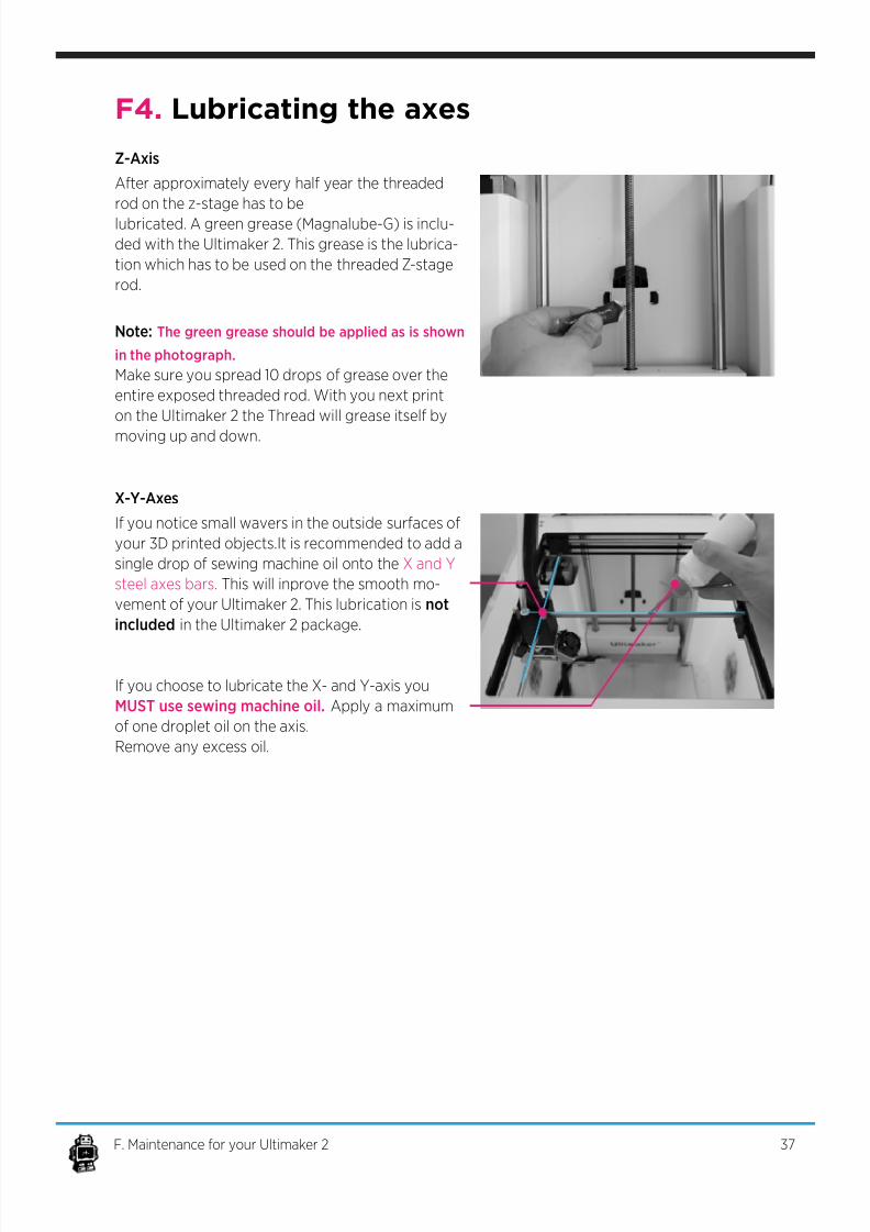
Z-Axis
X-Y-Axes
After approximately every half year the threaded
rod on the z-stage has to be
lubricated. A green grease (Magnalube-G) is inclu-
ded with the Ultimaker 2. This grease is the lubrica-
tion which has to be used on the threaded Z-stage
rod.
Note: The green grease should be applied as is shown
in the photograph.
Make sure you spread 10 drops of grease over the
entire exposed threaded rod. With you next print
on the Ultimaker 2 the Thread will grease itself by
moving up and down.
If you notice small wavers in the outside surfaces of
your 3D printed objects.It is recommended to add a
single drop of sewing machine oil onto the X and Y
steel axes bars. This will inprove the smooth mo-
vement of your Ultimaker 2. This lubrication is not
included in the Ultimaker 2 package.
If you choose to lubricate the X- and Y-axis you
MUST use sewing machine oil. Apply a maximum
of one droplet oil on the axis.
Remove any excess oil.
37F. Maintenance for your Ultimaker 2

7/17/2019 Ultimaker 2 - User Manual v1.13
http://slidepdf.com/reader/full/ultimaker-2-user-manual-v113 38/50
TROUBLEHOOTING
AND SUPPORT
FOR THE
ULTIMAKER 2
38
7/17/2019 Ultimaker 2 - User Manual v1.13
http://slidepdf.com/reader/full/ultimaker-2-user-manual-v113 39/50
G1. Simple Troubleshooting tips
In case something goes wrong with your Ultimaker 2, the following chapter will help you.
From diagnosing and xing the problem yourself to contacting support.
Print detaches during printing or print does not
stick at all.
Cause
Build plate is not properly leveled.
Solution
Follow the instructions under [MAINTENANCE] and
then [BUILD-PLATE]
Second cause
Material is not adhering to the build plate.
Solution
Using a thin layer of the supplied glue-stick as discus-
sed in chapter D4.
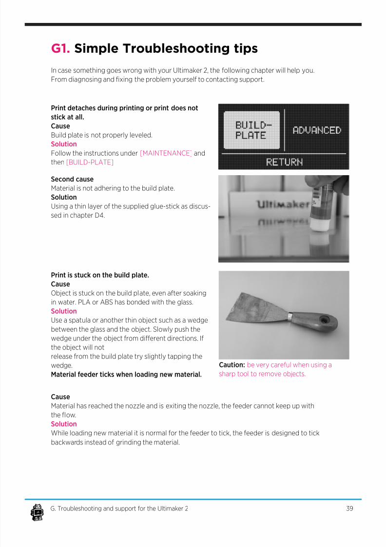
Print is stuck on the build plate.
Cause
Object is stuck on the build plate, even after soaking
in water. PLA or ABS has bonded with the glass.
Solution
Use a spatula or another thin object such as a wedge
between the glass and the object. Slowly push the
wedge under the object from dierent directions. If
the object will not
release from the build plate try slightly tapping the
wedge.
Material feeder ticks when loading new material.
Cause
Material has reached the nozzle and is exiting the nozzle, the feeder cannot keep up with
the ow.
Solution
While loading new material it is normal for the feeder to tick, the feeder is designed to tick
backwards instead of grinding the material.
Caution: be very careful when using a
sharp tool to remove objects.
39G. Troubleshooting and support for the Ultimaker 2
7/17/2019 Ultimaker 2 - User Manual v1.13
http://slidepdf.com/reader/full/ultimaker-2-user-manual-v113 40/50
Not enough material is released from the nozzle.
Cause
Material feeder on the back of the Ultimaker 2 is ticking while printing. Nozzle is blocked or
partially blocked by dirt or burned material.
SolutionIncreasing the print temperature to 260C while printing in an attempt to clear the blockage.
If the blockage is removed keep printing at 260C for at least 10 minutes to clean out any
residue.
Second cause
Printing at 260C does not solve the blockage.
Solution
Something larger than 0.4mm could be blocking the nozzle. Cleaning the nozzle or repla-
cing it is recommended. Contact support: [email protected] who will assist in xing
your Ultimaker 2.
Material ow stops and material is ground down by the feeder.
Cause
Nozzle could be blocked or partially blocked.
Solution
See ìNot enough material is released from the nozzle.î for causes and solutions.
Second cause
Too much pressure is put on the material by the feeder.
Solution
Release the pressure on the feeder a bit by adjusting the build plate screw clockwise.
Third cause
Too little pressure is put on the material by the feeder, causing the material to slip.Solution
Put more pressure on the feeder a bit by adjusting the pressure screw counter clockwise.
Ultimaker 2 display only shows: ERROR - STOPPED, Temp Sensor
Cause
A problem with the temperature measurement has been detected, the printer has been
switched o for safety reasons.
Solution
It indicates an electronics problem. Contact support: [email protected] who will assist
in xing your Ultimaker 2.
40G. Troubleshooting and support for the Ultimaker 2
Continued: Simple Troubleshooting tips

7/17/2019 Ultimaker 2 - User Manual v1.13
http://slidepdf.com/reader/full/ultimaker-2-user-manual-v113 41/50
In case you run into diculty not addressed in this manual, please feel free to contact our
support sta through email, phone and of course our support ticket system.
See w w w . u l t i m a k e r . c o m / p a g e s / s u p p o r t for details.
There is also a wealth of information, tips and amazing Ultimaker printed objects on our
busy online forum community. These forums can be reached online at
h t t p : / / u m f o r u m . u l t i m a k e r . c o m /
Drop by and say hello !
If you need any help resolving an issue you can always email our
support department at:
s u p p o r t @ u l t i m a k e r . c o m
G2. Contact support
41G. Troubleshooting and support for the Ultimaker 2
7/17/2019 Ultimaker 2 - User Manual v1.13
http://slidepdf.com/reader/full/ultimaker-2-user-manual-v113 42/50
ABS lament: This is a well-known plastic
known for its strength and industrial properties.
Active cooling fan: The fan that cools the print
head as it is printing.Build plate: The frame that supports the glass
print plate.
Cura: Open Source Software that allows you to
turn your 3D model into a printable le.
Display: The OLED display provides the menu
for controlling the Ultimaker 2.
Filament guide tube: The plastic tube that gui-
des the lament from the material feeder to the
print head.
Firmware: The software that runs on the elec-
tronic board.
Gantry: The construction of metal rods that
allow movements on the x- y- and z-axis.
G-code: The code that comes out of the slicing
process of a 3D model in Cura. It describes the
movements of your print head.
Glue: The glue can be used as an adhesive bet-
ween your build plate and your model.
Knurled wheel: Gives grip to push the lament in
the lament guide tube.
LED strip: It is a strip which contains severalsmall lights (Light Emitting Diodes) to light the
Ultimaker 2.
Material feeder: The feeder that drives the
lament through the lament guide tube into the
heater.
Material feeder tensioner: The tension with
which the lament is pushed through material
feeder can be adjusted by tuning this tensioner.
Nozzle: The opening at the end of the print
head. The lament is being pushed through the
opening and will put down on your build plate.
PLA lament: This is a hard bioplastic that has
a low environmental impact. It is derived from
renewable, starch-based resources. It has a very
low shrinkage which is helpful for great prints.
Build plate screws: These screws can adjust the
leveling of the build plate.
Power supply: The A/C power supply. It con-
sists of a block and a power cable. The cable can
have dierent power plugs (US, EU,AU,UK). It
depends on what kind of electric outlet is used in
a country.
Power switch: Turns the Ultimaker on or o.Print head: The assembly that melts the lament
and pushes it through the nozzle onto the build
plate.
Print head fans: The fans which cool the la-
ment as soon as it is put onto the build plate.
Push button: By rotating and pushing the but-
ton in front of the Ultimaker 2, you can access
the control panel.
SD-card: Secure Digital memory card that can
store digital data. The card that can be used with
the Ultimaker has to be an SD-card and not an
SDHC card. It has to be formatted with FAT16 or
FAT32 with a maximum capacity of 2GB.
Slicing: The process that turns a 3D model into
code that can be used with 3D printers.
Slider blocks: The slider blocks maintain the
connection between the gantry axes.
Spool holder: The plastic piece attached to the
back of the Ultimaker 2. It can hold dierent
kinds of lament spools.
.stl: A widely used le format for 3D models.Threaded rod: The long rod behind the build
plate which is threaded. This rod makes the build
move up and down.
USB cable: The cable that allows direct commu-
nication between the Ultimaker and a computer,
using the USB interface on the computer.
YouMagine.com: A website where you can share
your models and download (3D) models from
the people within the youmagine communnity.
G3. Terminology
42G. Troubleshooting and support for the Ultimaker 2
7/17/2019 Ultimaker 2 - User Manual v1.13
http://slidepdf.com/reader/full/ultimaker-2-user-manual-v113 43/50
G4. Safety and Compliance
43G. Troubleshooting and support for the Ultimaker 2
Electromagnetic compatibility (EMC)
This is a class A product. In a domestic environment this product may cause radio interference
in which case the user may be required to take adequate measures.
The Ultimaker 2 can in very rare cases temporarily lose display function caused by ESD. Dis-
play function can be fully restored by turning the machine o and then on again.
The EMC test report of the Ultimaker 2 is available on request at [email protected]
Electrical safety
The Ultimaker 2 operates on 24 volts (Extra-low-voltage) and is therefore outside the scope
of the low-voltage directive. The power supply meets all CE mark regulations and is protected
against short-circuit, overload, over voltage and over temperature. For more information con-
cerning electrical safety aspects we refer you to the Mean Well EC-Conformity Declaration for
the GS220AX power adaptors.
Only use the Ultimaker 2 with power supplies and cables supplied bij Ultimaker B.V..
Always unplug the printer before maintenance or modications.
Mechanical safety
The Ultimaker 2 contains many moving parts, but the stepper motors do not have enough
power to cause serious injuries and moving gears have been covered. Still, it is advised to only
reach in the machine when it is turned o.
Always unplug the printer before maintenance or modications.
Risk of burns
There is a potential risk of burns, as the print-head can reach temperatures of up to 260°C and
the heated bed of up to 120°C. The nozzle of the print-head is mostly surrounded by an alu-
minum cover to prevent contact, but still we advise against reaching in the machine when the
print-head and/or heated bed are hot.
Always let the printer cool down for at least 30 minutes before maintenance or
modications.
Health
The Ultimaker 2 is designed to print with PLA and ABS laments. The use of other materials is
at your own risk.
When printing ABS, small concentrations of Styrene vapor can be released. This can (in some
cases) cause headaches, fatigue, dizziness, confusion, drowsiness, malaise, diculty in con-
centrating, and a feeling of intoxication. Therefore good ventilation is required, and long term
exposure should be avoided. It is advisable to use a fume hood (with active carbon ltering for
ductless extraction). Fume extraction is mandatory for use in oces, classrooms and alike.
!
!
!

7/17/2019 Ultimaker 2 - User Manual v1.13
http://slidepdf.com/reader/full/ultimaker-2-user-manual-v113 44/50
Printing pure PLA is considered safe, although good ventilation is still advised for possible
unknown vapors released from coloring dyes in colored PLA.
Only use your printer in a well-ventilated area.
General safety information
The Ultimaker 2 is not intended for use by persons (including children) with reduced physical
and/or mental capabilities, or lack of experience and knowledge, unless they have been given
supervision or instruction concerning the use of the appliance by a person responsible for their
safety.
Children should be under constant supervision when using the printer.
The above information is believed to be correct but does not purport to be all inclusive and
shall be used only as a guide.
The conditions or methods used for assembling, handling, storage, use or disposal of thedevice are beyond our control and may be beyond our knowledge. For this and other reasons,
we do not assume responsibility and expressly disclaim liability for loss, injuries, damage, or
expense arising out of or in any way connected with the assembly, handling, storage, use or
disposal of the product.
The information in this document was obtained from sources which we believe are reliable.
However, the information is provided without any warranty, express or implied, regarding its
correctness.
44G. Troubleshooting and support for the Ultimaker 2
!

7/17/2019 Ultimaker 2 - User Manual v1.13
http://slidepdf.com/reader/full/ultimaker-2-user-manual-v113 45/50
7/17/2019 Ultimaker 2 - User Manual v1.13
http://slidepdf.com/reader/full/ultimaker-2-user-manual-v113 46/50
TERMS OF SERVICE 1/2
Returning Purchased Items. ** LIMITED **
Ultimaker accepts returns on a very limited basis: for any electronic items, the Company ac-
cepts returns only on unaected devices within 14 calendar days from the date of receipt of
merchandise. “Unaected” means a device has never been assembled, powered up, program-med, or otherwise changed. Similarly, for non-electronic items, the Company accepts returns
only on unopened items within 14 calendar days from the date of receipt of merchandise. After
14 days, all sales are considered nal.
Warranty**LIMITED**
Ultimaker products are warranted only to the original purchaser for a period of three
months from the original purchase date, under normal use and service, against defective work-
manship and material.
This warranty is void if the product has been damaged by accident or unreasonable use, im-mersion in water, neglect, abuse, battery leakage or improper installation, improper service, or
other causes not arising out of defects in workmanship or materials of the product. All warran-
ty claims are subject to:
Ultimaker being notied of the warranty claim within the warranty period Ultimaker
verifying the existence of a defect in the productReceipt of valid proof of your purchase date.
Note: Please make sure that you have a valid proof of purchase (Receipt) before
contacting Customer Service.
Note: Please make sure to retain your original packaging in case of warranty service.
In the event that you experience any problems with your Ultimaker product and before return-
ing a product for any reason, it is necessary to contact the Ultimaker Support team to determi-
ne and diagnose the issues you are experiencing prior to taking any other course of action. To
communicate with Ultimaker Support, you can open a support ticket at:
h t t p s : / / w w w . u l t i m a k e r . c o m / p a g e s / s u p p o r t or email s u p p o r t @ u l t i m a k e r. c o m
If the service representative is unable to solve the problem, you will be provided with instructi-
ons as to how to go about having the unit repaired or replaced if it is under warranty. Return of
a product under warranty is governed by the following rules -- you must return your product,
shipping prepaid and with proof of purchase date, as instructed by a Ultimaker service repre-sentative.
46TERMS OF SERVICE

7/17/2019 Ultimaker 2 - User Manual v1.13
http://slidepdf.com/reader/full/ultimaker-2-user-manual-v113 47/50
TERMS OF SERVICE 2/2
In the event that a product under warranty is repaired or replaced, the replacement will be
covered under the original warranty or for 30 days, whichever is longer. Repair or replacement
is your exclusive remedy, and Ultimaker’s exclusive liability, under this warranty.
Replacement may consist of replacing the product with the same product or with a dierent
product of the same value. Ultimaker shall not be liable for any incidental or consequential da-
mages for the breach of any warranty on this product. Any implied warranty of merchantability
or tness for a particular purpose on this product is limited to the duration of this warranty.
47TERMS OF SERVICE

7/17/2019 Ultimaker 2 - User Manual v1.13
http://slidepdf.com/reader/full/ultimaker-2-user-manual-v113 48/50
48
Notes

7/17/2019 Ultimaker 2 - User Manual v1.13
http://slidepdf.com/reader/full/ultimaker-2-user-manual-v113 49/50

7/17/2019 Ultimaker 2 - User Manual v1.13
http://slidepdf.com/reader/full/ultimaker-2-user-manual-v113 50/50


![Vkbd3i Manual v1.13[1]](https://img.pdfslide.us/doc/110x75/552085894979598e2f8b4b28/vkbd3i-manual-v1131.jpg)
![Manuale Cura Ultimaker [ ITA ] by StudioSBAM](https://img.pdfslide.us/doc/110x75/568c56441a28ab4916c5f34a/manuale-cura-ultimaker-ita-by-studiosbam.jpg)