Embed Size (px)
Citation preview
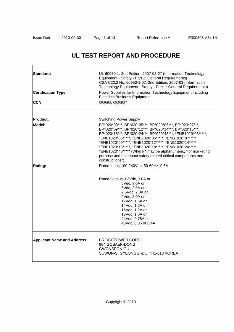
Issue Date: 2010-09-30 Page 1 of 14 Report Reference # E300305-A54-UL
Copyright © 2010
UL TEST REPORT AND PROCEDURE
Standard: UL 60950-1, 2nd Edition, 2007-03-27 (Information Technology Equipment - Safety - Part 1: General Requirements) CSA C22.2 No. 60950-1-07, 2nd Edition, 2007-03 (Information Technology Equipment - Safety - Part 1: General Requirements)
Certification Type: Power Supplies for Information Technology Equipment Including Electrical Business Equipment
CCN: QQGQ, QQGQ7
Product: Switching Power Supply
Model: BP*020*03***, BP*020*05***, BP*020*06***, BP*020*07***, BP*020*09***, BP*020*12***, BP*020*14***, BP*020*15***, BP*020*18***, BP*020*24***, BP*020*48***, *ENB1020*03*****, *ENB1020*05*****, *ENB1020*06*****, *ENB1020*07*****, *ENB1020*09*****, *ENB1020*12*****, *ENB1020*14*****, *ENB1020*15*****, *ENB1020*18*****, *ENB1020*24*****, *ENB1020*48***** (Where * may be alphanumeric, "for marketing purpose and no impact safety related critical components and constructions")
Rating: Rated Input; 100-240Vac, 50-60Hz, 0.5A Rated Output; 3.3Vdc, 3.0A or 5Vdc, 3.0A or 6Vdc, 2.5A or 7.5Vdc, 2.0A or 9Vdc, 2.0A or 12Vdc, 1.5A or 14Vdc, 1.2A or 15Vdc, 1.2A or 18Vdc, 1.0A or 24Vdc, 0.75A or 48Vdc, 0.35 or 0.4A
Applicant Name and Address: BRIDGEPOWER CORP 964 GOSAEK-DONG GWONSEON-GU SUWON-SI GYEONGGI-DO 441-813 KOREA

Issue Date: 2010-09-30 Page 2 of 14 Report Reference # E300305-A54-UL
Copyright © 2010
This is to certify that representative samples of the products covered by this Test Report have been investigated in accordance with the above referenced Standards. The products have been found to comply with the requirements covering the category and the products are judged to be eligible for Follow-Up Service under the indicated Test Procedure. The manufacturer is authorized to use the UL Mark on such products which comply with this Test Report and any other applicable requirements of Underwriters Laboratories Inc. ('UL') in accordance with the Follow-Up Service Agreement. Only those products which properly bear the UL Mark are considered as being covered by UL's Follow-Up Service under the indicated Test Procedure. The applicant is authorized to reproduce the referenced Test Report provided it is reproduced in its entirety. Any information and documentation involving UL Mark services are provided on behalf of Underwriters Laboratories Inc. (UL) or any authorized licensee of UL.
Prepared by: In-Young Hwang
Underwriters Laboratories Inc.
Reviewed by: HackSoo Song
Underwriters Laboratories Inc.
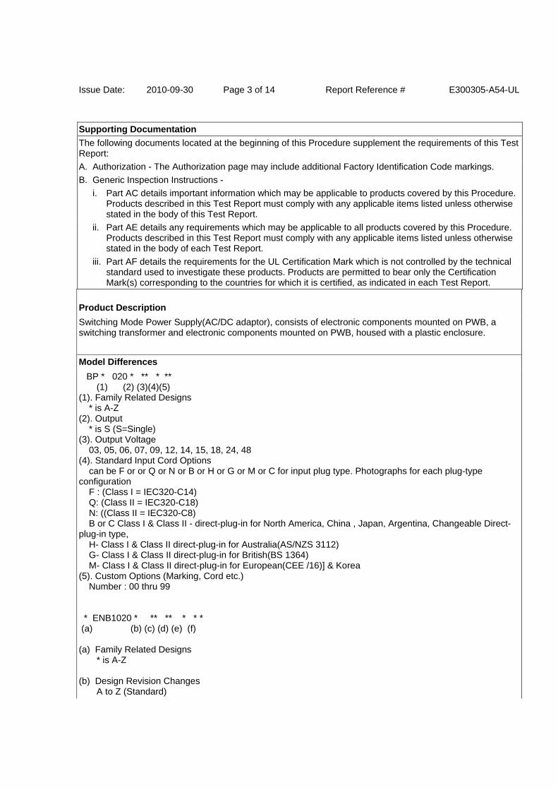
Issue Date: 2010-09-30 Page 3 of 14 Report Reference # E300305-A54-UL
Supporting Documentation
The following documents located at the beginning of this Procedure supplement the requirements of this Test Report:
A. Authorization - The Authorization page may include additional Factory Identification Code markings.
B. Generic Inspection Instructions -
i. Part AC details important information which may be applicable to products covered by this Procedure. Products described in this Test Report must comply with any applicable items listed unless otherwise stated in the body of this Test Report.
ii. Part AE details any requirements which may be applicable to all products covered by this Procedure. Products described in this Test Report must comply with any applicable items listed unless otherwise stated in the body of each Test Report.
iii. Part AF details the requirements for the UL Certification Mark which is not controlled by the technical standard used to investigate these products. Products are permitted to bear only the Certification Mark(s) corresponding to the countries for which it is certified, as indicated in each Test Report.
Product Description
Switching Mode Power Supply(AC/DC adaptor), consists of electronic components mounted on PWB, a switching transformer and electronic components mounted on PWB, housed with a plastic enclosure.
Model Differences
BP * 020 * ** * ** (1) (2) (3)(4)(5) (1). Family Related Designs * is A-Z (2). Output * is S (S=Single) (3). Output Voltage 03, 05, 06, 07, 09, 12, 14, 15, 18, 24, 48 (4). Standard Input Cord Options can be F or or Q or N or B or H or G or M or C for input plug type. Photographs for each plug-type configuration F : (Class I = IEC320-C14) Q: (Class II = IEC320-C18) N: ((Class II = IEC320-C8) B or C Class I & Class II - direct-plug-in for North America, China , Japan, Argentina, Changeable Direct-plug-in type, H- Class I & Class II direct-plug-in for Australia(AS/NZS 3112) G- Class I & Class II direct-plug-in for British(BS 1364) M- Class I & Class II direct-plug-in for European(CEE /16)] & Korea (5). Custom Options (Marking, Cord etc.) Number : 00 thru 99 * ENB1020 * ** ** * * * (a) (b) (c) (d) (e) (f) (a) Family Related Designs * is A-Z (b) Design Revision Changes A to Z (Standard)
Issue Date: 2010-09-30 Page 4 of 14 Report Reference # E300305-A54-UL
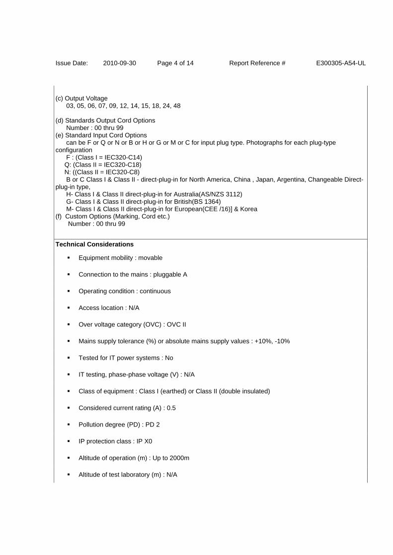
(c) Output Voltage 03, 05, 06, 07, 09, 12, 14, 15, 18, 24, 48 (d) Standards Output Cord Options Number : 00 thru 99 (e) Standard Input Cord Options can be F or Q or N or B or H or G or M or C for input plug type. Photographs for each plug-type configuration F : (Class I = IEC320-C14) Q: (Class II = IEC320-C18) N: ((Class II = IEC320-C8) B or C Class I & Class II - direct-plug-in for North America, China , Japan, Argentina, Changeable Direct-plug-in type, H- Class I & Class II direct-plug-in for Australia(AS/NZS 3112) G- Class I & Class II direct-plug-in for British(BS 1364) M- Class I & Class II direct-plug-in for European(CEE /16)] & Korea (f) Custom Options (Marking, Cord etc.) Number : 00 thru 99
Technical Considerations
Equipment mobility : movable
Connection to the mains : pluggable A
Operating condition : continuous
Access location : N/A
Over voltage category (OVC) : OVC II
Mains supply tolerance (%) or absolute mains supply values : +10%, -10%
Tested for IT power systems : No
IT testing, phase-phase voltage (V) : N/A
Class of equipment : Class I (earthed) or Class II (double insulated)
Considered current rating (A) : 0.5
Pollution degree (PD) : PD 2
IP protection class : IP X0
Altitude of operation (m) : Up to 2000m
Altitude of test laboratory (m) : N/A
Issue Date: 2010-09-30 Page 5 of 14 Report Reference # E300305-A54-UL
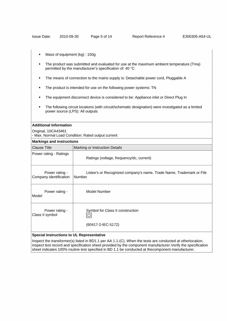
Mass of equipment (kg) : 150g
The product was submitted and evaluated for use at the maximum ambient temperature (Tma) permitted by the manufacturer’s specification of: 40 °C
The means of connection to the mains supply is: Detachable power cord, Pluggable A
The product is intended for use on the following power systems: TN
The equipment disconnect device is considered to be: Appliance inlet or Direct Plug In
The following circuit locations (with circuit/schematic designation) were investigated as a limited power source (LPS): All outputs
Additional Information
Original, 10CA43461 - Max. Normal Load Condition: Rated output current
Markings and instructions
Clause Title Marking or Instruction Details
Power rating - Ratings Ratings (voltage, frequency/dc, current)
Power rating - Company identification
Listee's or Recognized company's name, Trade Name, Trademark or File Number
Power rating - Model
Model Number
Power rating - Class II symbol
Symbol for Class II construction
(60417-2-IEC-5172)
Special Instructions to UL Representative
Inspect the transformer(s) listed in BD1.1 per AA 1.1-(C). When the tests are conducted at otherlocation, inspect test record and specification sheet provided by the component manufacturer.Verify the specification sheet indicates 100% routine test specified in BD 1.1 be conducted at thecomponent manufacturer.
Issue Date: 2010-09-30 Page 6 of 14 Report Reference # E300305-A54-UL
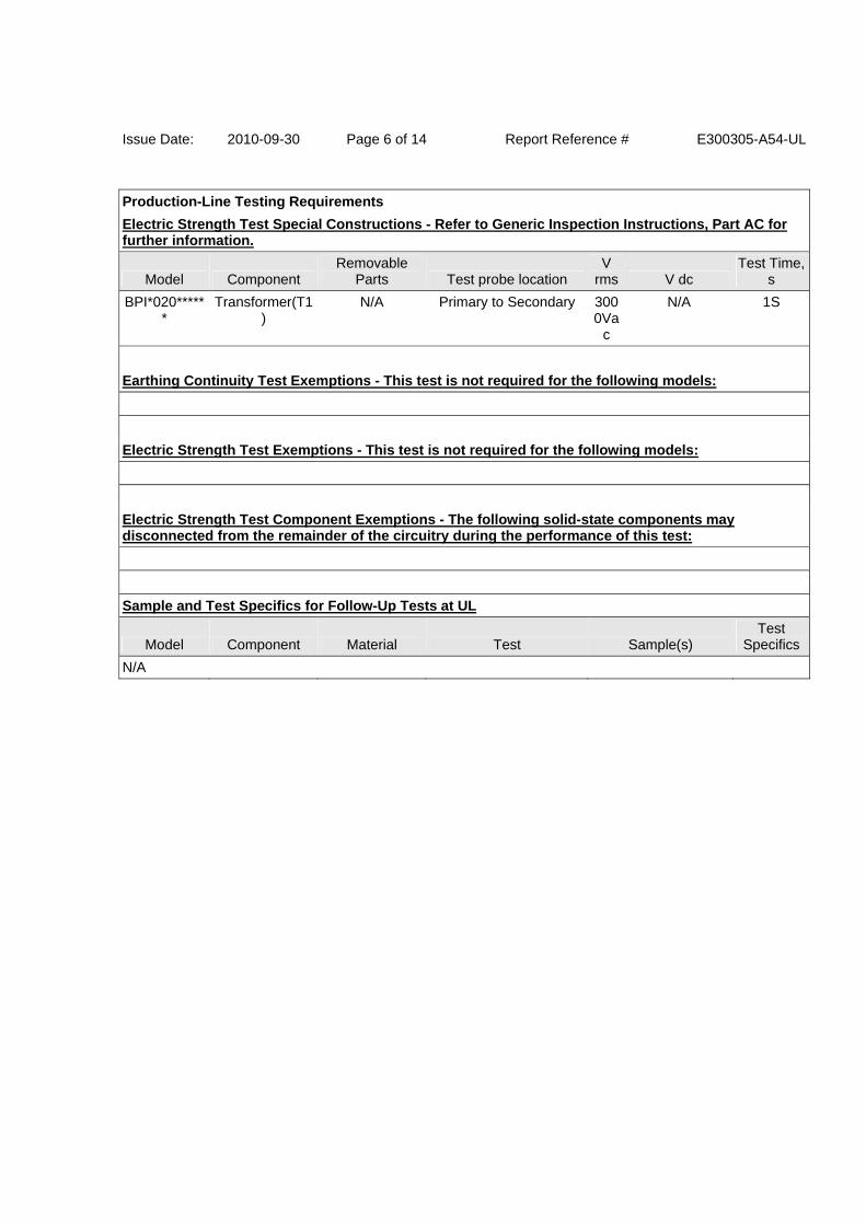
Production-Line Testing Requirements
Electric Strength Test Special Constructions - Refer to Generic Inspection Instructions, Part AC for further information.
Model Component Removable
Parts Test probe location V
rms V dc Test Time,
s
BPI*020******
Transformer(T1)
N/A Primary to Secondary 3000Va
c
N/A 1S
Earthing Continuity Test Exemptions - This test is not required for the following models:
Electric Strength Test Exemptions - This test is not required for the following models:
Electric Strength Test Component Exemptions - The following solid-state components may disconnected from the remainder of the circuitry during the performance of this test:
Sample and Test Specifics for Follow-Up Tests at UL
Model Component Material Test Sample(s) Test
Specifics
N/A
Issue Date: 2010-09-30 Page 7 of 14 Report Reference # E300305-A54-UL
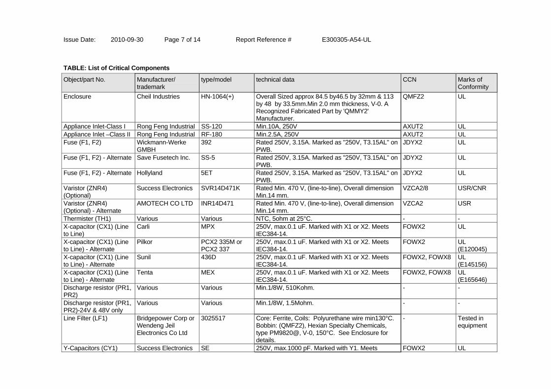
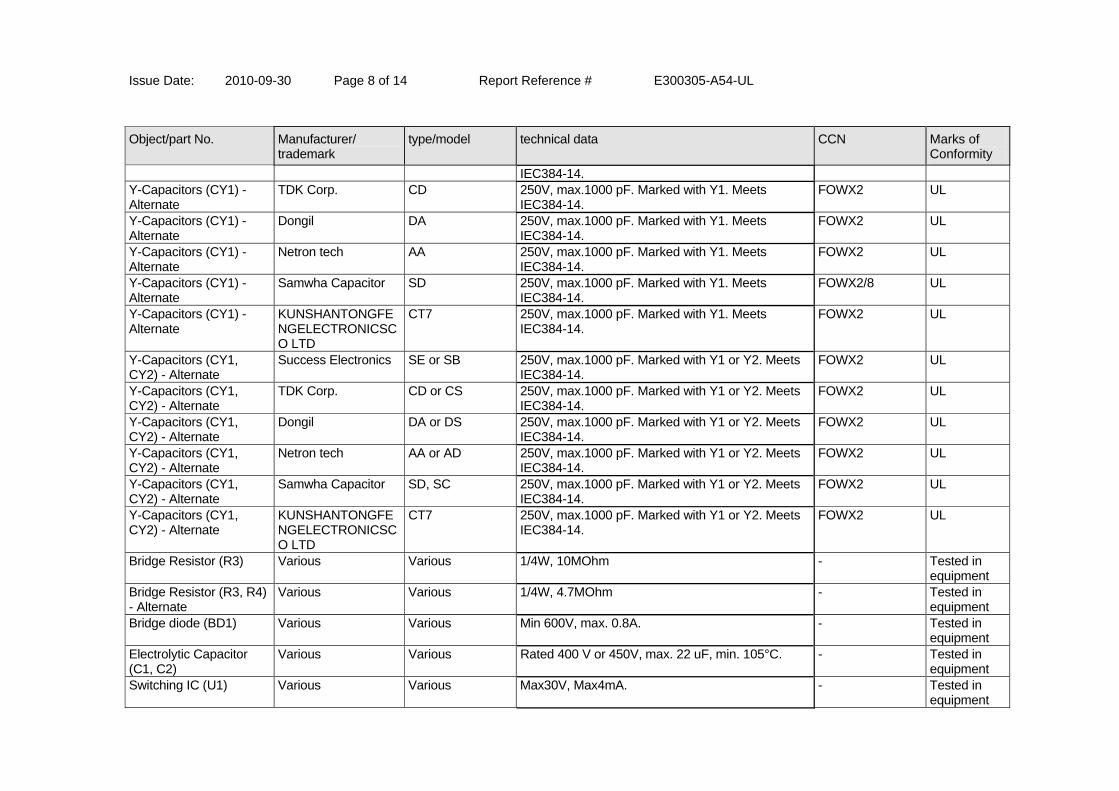
TABLE: List of Critical Components
Object/part No. Manufacturer/ trademark
type/model technical data CCN Marks of Conformity
Enclosure Cheil Industries HN-1064(+) Overall Sized approx 84.5 by46.5 by 32mm & 113 by 48 by 33.5mm.Min 2.0 mm thickness, V-0. A Recognized Fabricated Part by 'QMMY2' Manufacturer.
QMFZ2 UL
Appliance Inlet-Class I Rong Feng Industrial SS-120 Min.10A, 250V AXUT2 UL Appliance Inlet –Class II Rong Feng Industrial RF-180 Min.2.5A, 250V AXUT2 UL Fuse (F1, F2) Wickmann-Werke
GMBH 392 Rated 250V, 3.15A. Marked as "250V, T3.15AL" on
PWB. JDYX2 UL
Fuse (F1, F2) - Alternate Save Fusetech Inc. SS-5 Rated 250V, 3.15A. Marked as "250V, T3.15AL" on PWB.
JDYX2 UL
Fuse (F1, F2) - Alternate Hollyland 5ET Rated 250V, 3.15A. Marked as "250V, T3.15AL" on PWB.
JDYX2 UL
Varistor (ZNR4) (Optional)
Success Electronics SVR14D471K Rated Min. 470 V, (line-to-line), Overall dimension Min.14 mm.
VZCA2/8 USR/CNR
Varistor (ZNR4) (Optional) - Alternate
AMOTECH CO LTD INR14D471 Rated Min. 470 V, (line-to-line), Overall dimension Min.14 mm.
VZCA2 USR
Thermister (TH1) Various Various NTC, 5ohm at 25°C. - - X-capacitor (CX1) (Line to Line)
Carli MPX 250V, max.0.1 uF. Marked with X1 or X2. Meets IEC384-14.
FOWX2 UL
X-capacitor (CX1) (Line to Line) - Alternate
Pilkor PCX2 335M or PCX2 337
250V, max.0.1 uF. Marked with X1 or X2. Meets IEC384-14.
FOWX2 UL (E120045)
X-capacitor (CX1) (Line to Line) - Alternate
Sunil 436D 250V, max.0.1 uF. Marked with X1 or X2. Meets IEC384-14.
FOWX2, FOWX8 UL (E145156)
X-capacitor (CX1) (Line to Line) - Alternate
Tenta MEX 250V, max.0.1 uF. Marked with X1 or X2. Meets IEC384-14.
FOWX2, FOWX8 UL (E165646)
Discharge resistor (PR1, PR2)
Various Various Min.1/8W, 510Kohm. - -
Discharge resistor (PR1, PR2)-24V & 48V only
Various Various Min.1/8W, 1.5Mohm. - -
Line Filter (LF1) Bridgepower Corp or Wendeng Jeil Electronics Co Ltd
3025517 Core: Ferrite, Coils: Polyurethane wire min130°C. Bobbin: (QMFZ2), Hexian Specialty Chemicals, type PM9820@, V-0, 150°C. See Enclosure for details.
- Tested in equipment
Y-Capacitors (CY1) Success Electronics SE 250V, max.1000 pF. Marked with Y1. Meets FOWX2 UL
Issue Date: 2010-09-30 Page 8 of 14 Report Reference # E300305-A54-UL
Object/part No. Manufacturer/ trademark
type/model technical data CCN Marks of Conformity
IEC384-14. Y-Capacitors (CY1) - Alternate
TDK Corp. CD 250V, max.1000 pF. Marked with Y1. Meets IEC384-14.
FOWX2 UL
Y-Capacitors (CY1) - Alternate
Dongil DA 250V, max.1000 pF. Marked with Y1. Meets IEC384-14.
FOWX2 UL
Y-Capacitors (CY1) - Alternate
Netron tech AA 250V, max.1000 pF. Marked with Y1. Meets IEC384-14.
FOWX2 UL
Y-Capacitors (CY1) - Alternate
Samwha Capacitor SD 250V, max.1000 pF. Marked with Y1. Meets IEC384-14.
FOWX2/8 UL
Y-Capacitors (CY1) - Alternate
KUNSHANTONGFENGELECTRONICSCO LTD
CT7 250V, max.1000 pF. Marked with Y1. Meets IEC384-14.
FOWX2 UL
Y-Capacitors (CY1, CY2) - Alternate
Success Electronics SE or SB 250V, max.1000 pF. Marked with Y1 or Y2. Meets IEC384-14.
FOWX2 UL
Y-Capacitors (CY1, CY2) - Alternate
TDK Corp. CD or CS 250V, max.1000 pF. Marked with Y1 or Y2. Meets IEC384-14.
FOWX2 UL
Y-Capacitors (CY1, CY2) - Alternate
Dongil DA or DS 250V, max.1000 pF. Marked with Y1 or Y2. Meets IEC384-14.
FOWX2 UL
Y-Capacitors (CY1, CY2) - Alternate
Netron tech AA or AD 250V, max.1000 pF. Marked with Y1 or Y2. Meets IEC384-14.
FOWX2 UL
Y-Capacitors (CY1, CY2) - Alternate
Samwha Capacitor SD, SC 250V, max.1000 pF. Marked with Y1 or Y2. Meets IEC384-14.
FOWX2 UL
Y-Capacitors (CY1, CY2) - Alternate
KUNSHANTONGFENGELECTRONICSCO LTD
CT7 250V, max.1000 pF. Marked with Y1 or Y2. Meets IEC384-14.
FOWX2 UL
Bridge Resistor (R3) Various Various 1/4W, 10MOhm - Tested in equipment
Bridge Resistor (R3, R4) - Alternate
Various Various 1/4W, 4.7MOhm - Tested in equipment
Bridge diode (BD1) Various Various Min 600V, max. 0.8A. - Tested in equipment
Electrolytic Capacitor (C1, C2)
Various Various Rated 400 V or 450V, max. 22 uF, min. 105°C. - Tested in equipment
Switching IC (U1) Various Various Max30V, Max4mA. - Tested in equipment
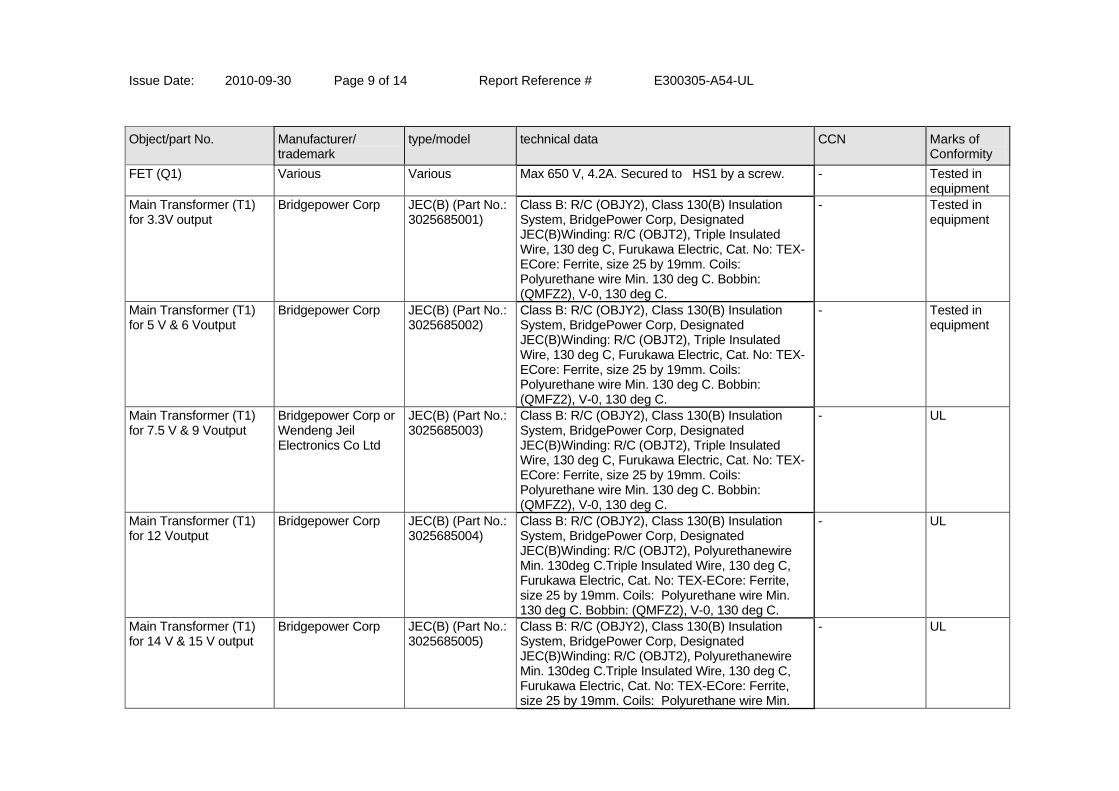
Issue Date: 2010-09-30 Page 9 of 14 Report Reference # E300305-A54-UL
Object/part No. Manufacturer/ trademark
type/model technical data CCN Marks of Conformity
FET (Q1) Various Various Max 650 V, 4.2A. Secured to HS1 by a screw. - Tested in equipment
Main Transformer (T1) for 3.3V output
Bridgepower Corp JEC(B) (Part No.: 3025685001)
Class B: R/C (OBJY2), Class 130(B) Insulation System, BridgePower Corp, Designated JEC(B)Winding: R/C (OBJT2), Triple Insulated Wire, 130 deg C, Furukawa Electric, Cat. No: TEX-ECore: Ferrite, size 25 by 19mm. Coils: Polyurethane wire Min. 130 deg C. Bobbin: (QMFZ2), V-0, 130 deg C.
- Tested in equipment
Main Transformer (T1) for 5 V & 6 Voutput
Bridgepower Corp JEC(B) (Part No.: 3025685002)
Class B: R/C (OBJY2), Class 130(B) Insulation System, BridgePower Corp, Designated JEC(B)Winding: R/C (OBJT2), Triple Insulated Wire, 130 deg C, Furukawa Electric, Cat. No: TEX-ECore: Ferrite, size 25 by 19mm. Coils: Polyurethane wire Min. 130 deg C. Bobbin: (QMFZ2), V-0, 130 deg C.
- Tested in equipment
Main Transformer (T1) for 7.5 V & 9 Voutput
Bridgepower Corp or Wendeng Jeil Electronics Co Ltd
JEC(B) (Part No.: 3025685003)
Class B: R/C (OBJY2), Class 130(B) Insulation System, BridgePower Corp, Designated JEC(B)Winding: R/C (OBJT2), Triple Insulated Wire, 130 deg C, Furukawa Electric, Cat. No: TEX-ECore: Ferrite, size 25 by 19mm. Coils: Polyurethane wire Min. 130 deg C. Bobbin: (QMFZ2), V-0, 130 deg C.
- UL
Main Transformer (T1) for 12 Voutput
Bridgepower Corp JEC(B) (Part No.: 3025685004)
Class B: R/C (OBJY2), Class 130(B) Insulation System, BridgePower Corp, Designated JEC(B)Winding: R/C (OBJT2), Polyurethanewire Min. 130deg C.Triple Insulated Wire, 130 deg C, Furukawa Electric, Cat. No: TEX-ECore: Ferrite, size 25 by 19mm. Coils: Polyurethane wire Min. 130 deg C. Bobbin: (QMFZ2), V-0, 130 deg C.
- UL
Main Transformer (T1) for 14 V & 15 V output
Bridgepower Corp JEC(B) (Part No.: 3025685005)
Class B: R/C (OBJY2), Class 130(B) Insulation System, BridgePower Corp, Designated JEC(B)Winding: R/C (OBJT2), Polyurethanewire Min. 130deg C.Triple Insulated Wire, 130 deg C, Furukawa Electric, Cat. No: TEX-ECore: Ferrite, size 25 by 19mm. Coils: Polyurethane wire Min.
- UL
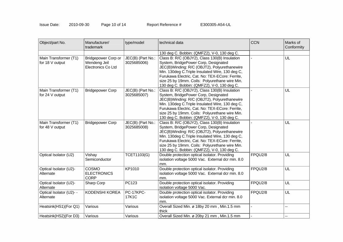
Issue Date: 2010-09-30 Page 10 of 14 Report Reference # E300305-A54-UL
Object/part No. Manufacturer/ trademark
type/model technical data CCN Marks of Conformity
130 deg C. Bobbin: (QMFZ2), V-0, 130 deg C. Main Transformer (T1) for 18 V output
Bridgepower Corp or Wendeng Jeil Electronics Co Ltd
JEC(B) (Part No.: 3025685006)
Class B: R/C (OBJY2), Class 130(B) Insulation System, BridgePower Corp, Designated JEC(B)Winding: R/C (OBJT2), Polyurethanewire Min. 130deg C.Triple Insulated Wire, 130 deg C, Furukawa Electric, Cat. No: TEX-ECore: Ferrite, size 25 by 19mm. Coils: Polyurethane wire Min. 130 deg C. Bobbin: (QMFZ2), V-0, 130 deg C.
- UL
Main Transformer (T1) for 24 V output
Bridgepower Corp JEC(B) (Part No.: 3025685007)
Class B: R/C (OBJY2), Class 130(B) Insulation System, BridgePower Corp, Designated JEC(B)Winding: R/C (OBJT2), Polyurethanewire Min. 130deg C.Triple Insulated Wire, 130 deg C, Furukawa Electric, Cat. No: TEX-ECore: Ferrite, size 25 by 19mm. Coils: Polyurethane wire Min. 130 deg C. Bobbin: (QMFZ2), V-0, 130 deg C.
- UL
Main Transformer (T1) for 48 V output
Bridgepower Corp JEC(B) (Part No.: 3025685008)
Class B: R/C (OBJY2), Class 130(B) Insulation System, BridgePower Corp, Designated JEC(B)Winding: R/C (OBJT2), Polyurethanewire Min. 130deg C.Triple Insulated Wire, 130 deg C, Furukawa Electric, Cat. No: TEX-ECore: Ferrite, size 25 by 19mm. Coils: Polyurethane wire Min. 130 deg C. Bobbin: (QMFZ2), V-0, 130 deg C.
- UL
Optical Isolator (U2) Vishay Semiconductor
TCET1103(G) Double protection optical isolator. Providing isolation voltage 5000 Vac. External dcr min. 8.0 mm.
FPQU2/8 UL
Optical Isolator (U2)- Alternate
COSMO ELECTRONICS CORP
KP1010 Double protection optical isolator. Providing isolation voltage 5000 Vac. External dcr min. 8.0 mm.
FPQU2/8 UL
Optical Isolator (U2)- Alternate
Sharp Corp PC123 Double protection optical isolator. Providing isolation voltage 5000 Vac.
FPQU2/8 UL
Optical Isolator (U2)- - Alternate
KODENSHI KOREA PC-17KPC-17K1C
Double protection optical isolator. Providing isolation voltage 5000 Vac. External dcr min. 8.0 mm.
FPQU2/8 UL
Heatsink(HS1)(For Q1) Various Various Overall Sized Min. ø 18by 20 mm , Min.1.5 mm thick
- --
Heatsink(HS2)(For D3) Various Various Overall Sized Min. ø 20by 21 mm , Min.1.5 mm - --
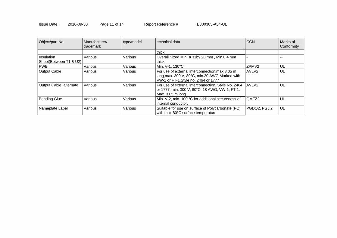
Issue Date: 2010-09-30 Page 11 of 14 Report Reference # E300305-A54-UL
Object/part No. Manufacturer/ trademark
type/model technical data CCN Marks of Conformity
thick Insulation Sheet(Between T1 & U2)
Various Various Overall Sized Min. ø 31by 20 mm , Min.0.4 mm thick
- --
PWB Various Various Min. V-1, 130°C. ZPMV2 UL Output Cable Various Various For use of external interconnection,max 3.05 m
long,max. 300 V, 80°C, min.20 AWG,Marked with VW-1 or FT-1.Style no. 2464 or 1777
AVLV2 UL
Output Cable_alternate Various Various For use of external interconnection, Style No. 2464 or 1777, min. 300 V, 80°C, 18 AWG, VW-1, FT-1. Max. 3.05 m long
AVLV2 UL
Bonding Glue Various Various Min. V-2, min. 100 °C for additional secureness of internal conductor.
QMFZ2 UL
Nameplate Label Various Various Suitable for use on surface of Polycarbonate (PC) with max.80°C surface temperature
PGDQ2, PGJI2 UL
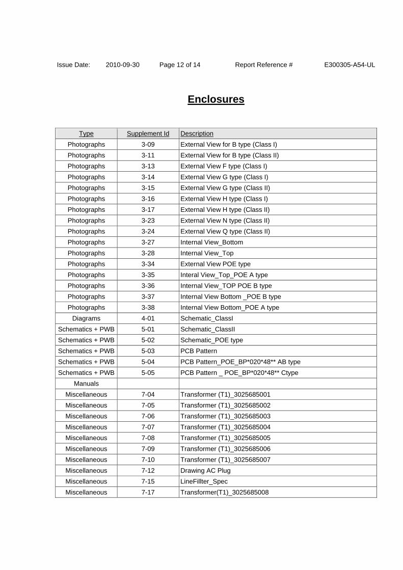
Issue Date: 2010-09-30 Page 12 of 14 Report Reference # E300305-A54-UL
Enclosures
Type Supplement Id Description
Photographs 3-09 External View for B type (Class I)
Photographs 3-11 External View for B type (Class II)
Photographs 3-13 External View F type (Class I)
Photographs 3-14 External View G type (Class I)
Photographs 3-15 External View G type (Class II)
Photographs 3-16 External View H type (Class I)
Photographs 3-17 External View H type (Class II)
Photographs 3-23 External View N type (Class II)
Photographs 3-24 External View Q type (Class II)
Photographs 3-27 Internal View_Bottom
Photographs 3-28 Internal View_Top
Photographs 3-34 External View POE type
Photographs 3-35 Interal View_Top_POE A type
Photographs 3-36 Internal View_TOP POE B type
Photographs 3-37 Internal View Bottom _POE B type
Photographs 3-38 Internal View Bottom_POE A type
Diagrams 4-01 Schematic_ClassI
Schematics + PWB 5-01 Schematic_ClassII
Schematics + PWB 5-02 Schematic_POE type
Schematics + PWB 5-03 PCB Pattern
Schematics + PWB 5-04 PCB Pattern_POE_BP*020*48** AB type
Schematics + PWB 5-05 PCB Pattern _ POE_BP*020*48** Ctype
Manuals
Miscellaneous 7-04 Transformer (T1)_3025685001
Miscellaneous 7-05 Transformer (T1)_3025685002
Miscellaneous 7-06 Transformer (T1)_3025685003
Miscellaneous 7-07 Transformer (T1)_3025685004
Miscellaneous 7-08 Transformer (T1)_3025685005
Miscellaneous 7-09 Transformer (T1)_3025685006
Miscellaneous 7-10 Transformer (T1)_3025685007
Miscellaneous 7-12 Drawing AC Plug
Miscellaneous 7-15 LineFillter_Spec
Miscellaneous 7-17 Transformer(T1)_3025685008
Issue Date: 2010-09-30 Page 13 of 14 Report Reference # E300305-A54-UL
Miscellaneous 7-18 Label_BP*020*03***_ClassI
Miscellaneous 7-19 Label_BP*020*03***_ClassII
Miscellaneous 7-20 Label_BP*020*05***_ClassII
Miscellaneous 7-21 Label_BP*020*05***_ClassI
Miscellaneous 7-22 Label_BP*020*06***_ClassI
Miscellaneous 7-23 Label_BP*020*06***_ClassII
Miscellaneous 7-24 Label_BP*020*07***_ClassI
Miscellaneous 7-25 Label_BP*020*07***_ClassII
Miscellaneous 7-26 Label_BP*020*09***_ClassI
Miscellaneous 7-27 Label_BP*020*09***_ClassII
Miscellaneous 7-28 Label_BP*020*12***_ClassI
Miscellaneous 7-29 Label_BP*020*12***_ClassII
Miscellaneous 7-30 Label_BP*020*14***_ClassI
Miscellaneous 7-31 Label_BP*020*14***_ClassII
Miscellaneous 7-32 Label_BP*020*15***_ClassI
Miscellaneous 7-33 Label_BP*020*15***_ClassII
Miscellaneous 7-34 Label_BP*020*18***_ClassI
Miscellaneous 7-35 Label_BP*020*18***_ClassII
Miscellaneous 7-36 Label_BP*020*24***_ClassI
Miscellaneous 7-37 Label_BP*020*24***_ClassII
Miscellaneous 7-38 Label_BP*020*48***_ClassI
Miscellaneous 7-39 Label_BP*020*48***_ClassII
Miscellaneous 7-40 Label_BP*020*48***_0.35A_ClassI
Miscellaneous 7-41 Label_BP*020*48***_0.35A_ClassII
Miscellaneous 7-42 Label_*ENB1020*03*****_ClassI
Miscellaneous 7-43 Label_*ENB1020*03*****_ClassII
Miscellaneous 7-44 Label_*ENB1020*05*****_ClassI
Miscellaneous 7-45 Label_*ENB1020*05*****_ClassII
Miscellaneous 7-46 Label_*ENB1020*06*****_ClassI
Miscellaneous 7-47 Label_*ENB1020*06*****_ClassII
Miscellaneous 7-48 Label_*ENB1020*07*****_ClassI
Miscellaneous 7-49 Label_*ENB1020*07*****_ClassII
Miscellaneous 7-50 Label_*ENB1020*09*****_ClassI
Miscellaneous 7-51 Label_*ENB1020*09*****_ClassII
Miscellaneous 7-52 Label_*ENB1020*12*****_ClassI
Miscellaneous 7-53 Label_*ENB1020*12*****_ClassII
Miscellaneous 7-54 Label_*ENB1020*14*****_ClassI
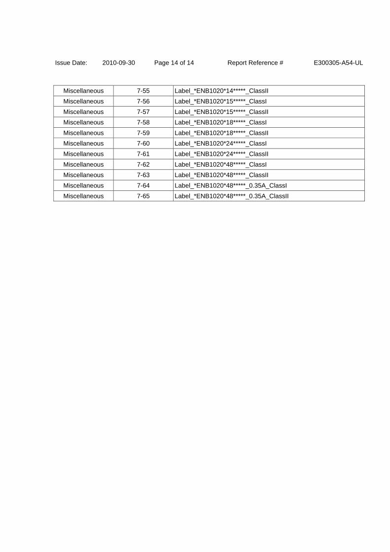
Issue Date: 2010-09-30 Page 14 of 14 Report Reference # E300305-A54-UL
Miscellaneous 7-55 Label_*ENB1020*14*****_ClassII
Miscellaneous 7-56 Label_*ENB1020*15*****_ClassI
Miscellaneous 7-57 Label_*ENB1020*15*****_ClassII
Miscellaneous 7-58 Label_*ENB1020*18*****_ClassI
Miscellaneous 7-59 Label_*ENB1020*18*****_ClassII
Miscellaneous 7-60 Label_*ENB1020*24*****_ClassI
Miscellaneous 7-61 Label_*ENB1020*24*****_ClassII
Miscellaneous 7-62 Label_*ENB1020*48*****_ClassI
Miscellaneous 7-63 Label_*ENB1020*48*****_ClassII
Miscellaneous 7-64 Label_*ENB1020*48*****_0.35A_ClassI
Miscellaneous 7-65 Label_*ENB1020*48*****_0.35A_ClassII
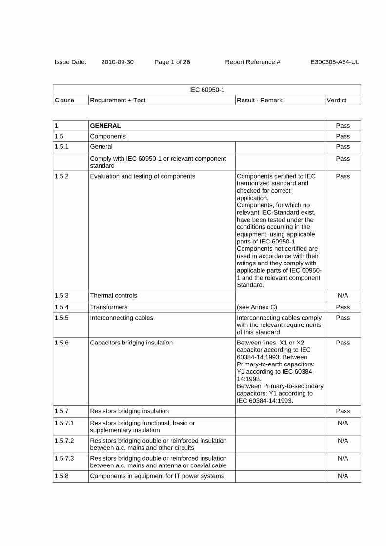
Issue Date: 2010-09-30 Page 1 of 26 Report Reference # E300305-A54-UL
IEC 60950-1
Clause Requirement + Test Result - Remark Verdict
1 GENERAL Pass
1.5 Components Pass
1.5.1 General Pass
Comply with IEC 60950-1 or relevant component standard
Pass
1.5.2 Evaluation and testing of components Components certified to IEC harmonized standard and checked for correct application. Components, for which no relevant IEC-Standard exist, have been tested under the conditions occurring in the equipment, using applicable parts of IEC 60950-1. Components not certified are used in accordance with their ratings and they comply with applicable parts of IEC 60950-1 and the relevant component Standard.
Pass
1.5.3 Thermal controls N/A
1.5.4 Transformers (see Annex C) Pass
1.5.5 Interconnecting cables Interconnecting cables comply with the relevant requirements of this standard.
Pass
1.5.6 Capacitors bridging insulation Between lines; X1 or X2 capacitor according to IEC 60384-14;1993. Between Primary-to-earth capacitors: Y1 according to IEC 60384-14:1993. Between Primary-to-secondary capacitors: Y1 according to IEC 60384-14:1993.
Pass
1.5.7 Resistors bridging insulation Pass
1.5.7.1 Resistors bridging functional, basic or supplementary insulation
N/A
1.5.7.2 Resistors bridging double or reinforced insulation between a.c. mains and other circuits
N/A
1.5.7.3 Resistors bridging double or reinforced insulation between a.c. mains and antenna or coaxial cable
N/A
1.5.8 Components in equipment for IT power systems N/A
Issue Date: 2010-09-30 Page 2 of 26 Report Reference # E300305-A54-UL
IEC 60950-1
Clause Requirement + Test Result - Remark Verdict
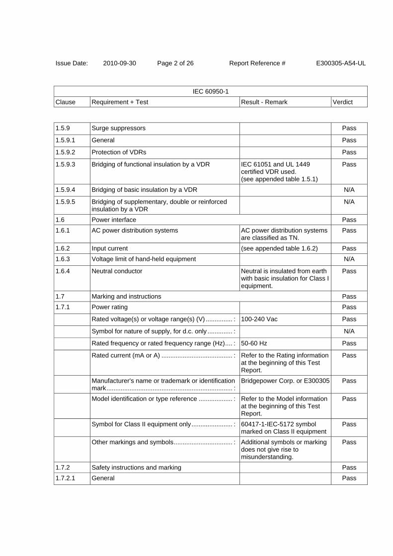
1.5.9 Surge suppressors Pass
1.5.9.1 General Pass
1.5.9.2 Protection of VDRs Pass
1.5.9.3 Bridging of functional insulation by a VDR IEC 61051 and UL 1449 certified VDR used. (see appended table 1.5.1)
Pass
1.5.9.4 Bridging of basic insulation by a VDR N/A
1.5.9.5 Bridging of supplementary, double or reinforced insulation by a VDR
N/A
1.6 Power interface Pass
1.6.1 AC power distribution systems AC power distribution systems are classified as TN.
Pass
1.6.2 Input current (see appended table 1.6.2) Pass
1.6.3 Voltage limit of hand-held equipment N/A
1.6.4 Neutral conductor Neutral is insulated from earth with basic insulation for Class I equipment.
Pass
1.7 Marking and instructions Pass
1.7.1 Power rating Pass
Rated voltage(s) or voltage range(s) (V) ............... : 100-240 Vac Pass
Symbol for nature of supply, for d.c. only .............. : N/A
Rated frequency or rated frequency range (Hz) .... : 50-60 Hz Pass
Rated current (mA or A) ........................................ : Refer to the Rating information at the beginning of this Test Report.
Pass
Manufacturer's name or trademark or identification mark ....................................................................... :
Bridgepower Corp. or E300305 Pass
Model identification or type reference ................... : Refer to the Model information at the beginning of this Test Report.
Pass
Symbol for Class II equipment only ....................... : 60417-1-IEC-5172 symbol marked on Class II equipment
Pass
Other markings and symbols ................................. : Additional symbols or marking does not give rise to misunderstanding.
Pass
1.7.2 Safety instructions and marking Pass
1.7.2.1 General Pass
Issue Date: 2010-09-30 Page 3 of 26 Report Reference # E300305-A54-UL
IEC 60950-1
Clause Requirement + Test Result - Remark Verdict
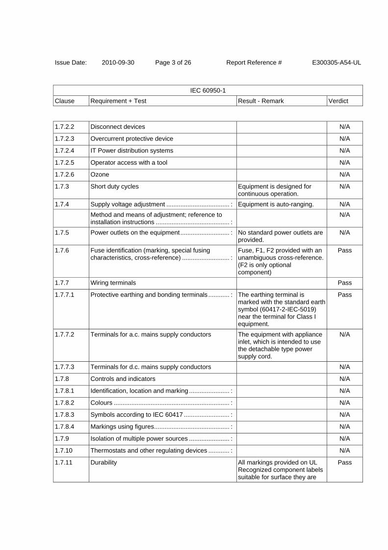
1.7.2.2 Disconnect devices N/A
1.7.2.3 Overcurrent protective device N/A
1.7.2.4 IT Power distribution systems N/A
1.7.2.5 Operator access with a tool N/A
1.7.2.6 Ozone N/A
1.7.3 Short duty cycles Equipment is designed for continuous operation.
N/A
1.7.4 Supply voltage adjustment .................................... : Equipment is auto-ranging. N/A
Method and means of adjustment; reference to installation instructions .......................................... :
N/A
1.7.5 Power outlets on the equipment ............................ : No standard power outlets are provided.
N/A
1.7.6 Fuse identification (marking, special fusing characteristics, cross-reference) ........................... :
Fuse, F1, F2 provided with an unambiguous cross-reference. (F2 is only optional component)
Pass
1.7.7 Wiring terminals Pass
1.7.7.1 Protective earthing and bonding terminals ............ : The earthing terminal is marked with the standard earth symbol (60417-2-IEC-5019) near the terminal for Class I equipment.
Pass
1.7.7.2 Terminals for a.c. mains supply conductors The equipment with appliance inlet, which is intended to use the detachable type power supply cord.
N/A
1.7.7.3 Terminals for d.c. mains supply conductors N/A
1.7.8 Controls and indicators N/A
1.7.8.1 Identification, location and marking ....................... : N/A
1.7.8.2 Colours .................................................................. : N/A
1.7.8.3 Symbols according to IEC 60417 .......................... : N/A
1.7.8.4 Markings using figures ........................................... : N/A
1.7.9 Isolation of multiple power sources ....................... : N/A
1.7.10 Thermostats and other regulating devices ............ : N/A
1.7.11 Durability All markings provided on UL Recognized component labels suitable for surface they are
Pass
Issue Date: 2010-09-30 Page 4 of 26 Report Reference # E300305-A54-UL
IEC 60950-1
Clause Requirement + Test Result - Remark Verdict
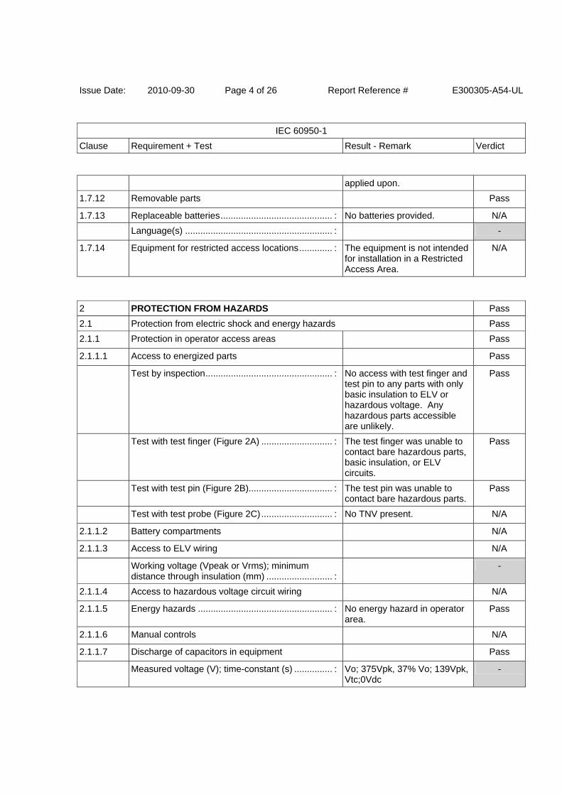
applied upon.
1.7.12 Removable parts Pass
1.7.13 Replaceable batteries ............................................ : No batteries provided. N/A
Language(s) .......................................................... : -
1.7.14 Equipment for restricted access locations ............. : The equipment is not intended for installation in a Restricted Access Area.
N/A
2 PROTECTION FROM HAZARDS Pass
2.1 Protection from electric shock and energy hazards Pass
2.1.1 Protection in operator access areas Pass
2.1.1.1 Access to energized parts Pass
Test by inspection .................................................. : No access with test finger and test pin to any parts with only basic insulation to ELV or hazardous voltage. Any hazardous parts accessible are unlikely.
Pass
Test with test finger (Figure 2A) ............................ : The test finger was unable to contact bare hazardous parts, basic insulation, or ELV circuits.
Pass
Test with test pin (Figure 2B)................................. : The test pin was unable to contact bare hazardous parts.
Pass
Test with test probe (Figure 2C) ............................ : No TNV present. N/A
2.1.1.2 Battery compartments N/A
2.1.1.3 Access to ELV wiring N/A
Working voltage (Vpeak or Vrms); minimum distance through insulation (mm) .......................... :
-
2.1.1.4 Access to hazardous voltage circuit wiring N/A
2.1.1.5 Energy hazards ..................................................... : No energy hazard in operator area.
Pass
2.1.1.6 Manual controls N/A
2.1.1.7 Discharge of capacitors in equipment Pass
Measured voltage (V); time-constant (s) ............... : Vo; 375Vpk, 37% Vo; 139Vpk, Vtc;0Vdc
-
Issue Date: 2010-09-30 Page 5 of 26 Report Reference # E300305-A54-UL
IEC 60950-1
Clause Requirement + Test Result - Remark Verdict
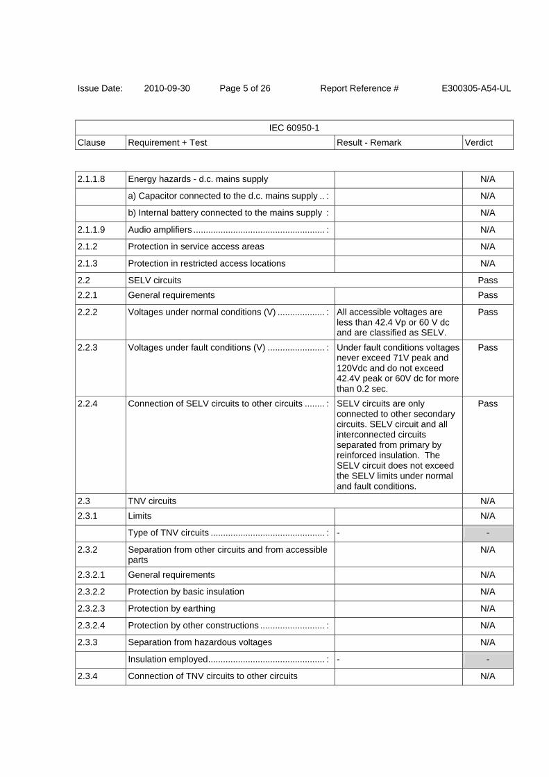
2.1.1.8 Energy hazards - d.c. mains supply N/A
a) Capacitor connected to the d.c. mains supply .. : N/A
b) Internal battery connected to the mains supply : N/A
2.1.1.9 Audio amplifiers ..................................................... : N/A
2.1.2 Protection in service access areas N/A
2.1.3 Protection in restricted access locations N/A
2.2 SELV circuits Pass
2.2.1 General requirements Pass
2.2.2 Voltages under normal conditions (V) ................... : All accessible voltages are less than 42.4 Vp or 60 V dc and are classified as SELV.
Pass
2.2.3 Voltages under fault conditions (V) ....................... : Under fault conditions voltages never exceed 71V peak and 120Vdc and do not exceed 42.4V peak or 60V dc for more than 0.2 sec.
Pass
2.2.4 Connection of SELV circuits to other circuits ........ : SELV circuits are only connected to other secondary circuits. SELV circuit and all interconnected circuits separated from primary by reinforced insulation. The SELV circuit does not exceed the SELV limits under normal and fault conditions.
Pass
2.3 TNV circuits N/A
2.3.1 Limits N/A
Type of TNV circuits .............................................. : - -
2.3.2 Separation from other circuits and from accessible parts
N/A
2.3.2.1 General requirements N/A
2.3.2.2 Protection by basic insulation N/A
2.3.2.3 Protection by earthing N/A
2.3.2.4 Protection by other constructions .......................... : N/A
2.3.3 Separation from hazardous voltages N/A
Insulation employed ............................................... : - -
2.3.4 Connection of TNV circuits to other circuits N/A
Issue Date: 2010-09-30 Page 6 of 26 Report Reference # E300305-A54-UL
IEC 60950-1
Clause Requirement + Test Result - Remark Verdict
Insulation employed ............................................... : - -
2.3.5 Test for operating voltages generated externally N/A
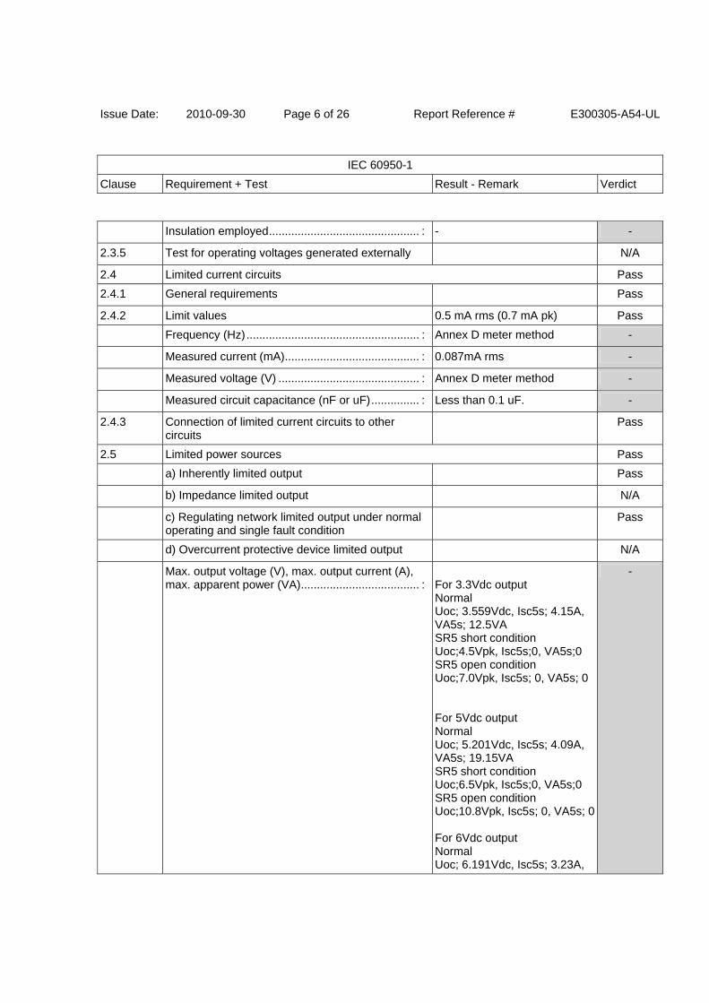
2.4 Limited current circuits Pass
2.4.1 General requirements Pass
2.4.2 Limit values 0.5 mA rms (0.7 mA pk) Pass
Frequency (Hz) ...................................................... : Annex D meter method -
Measured current (mA) .......................................... : 0.087mA rms -
Measured voltage (V) ............................................ : Annex D meter method -
Measured circuit capacitance (nF or uF) ............... : Less than 0.1 uF. -
2.4.3 Connection of limited current circuits to other circuits
Pass
2.5 Limited power sources Pass
a) Inherently limited output Pass
b) Impedance limited output N/A
c) Regulating network limited output under normal operating and single fault condition
Pass
d) Overcurrent protective device limited output N/A
Max. output voltage (V), max. output current (A), max. apparent power (VA) ..................................... :
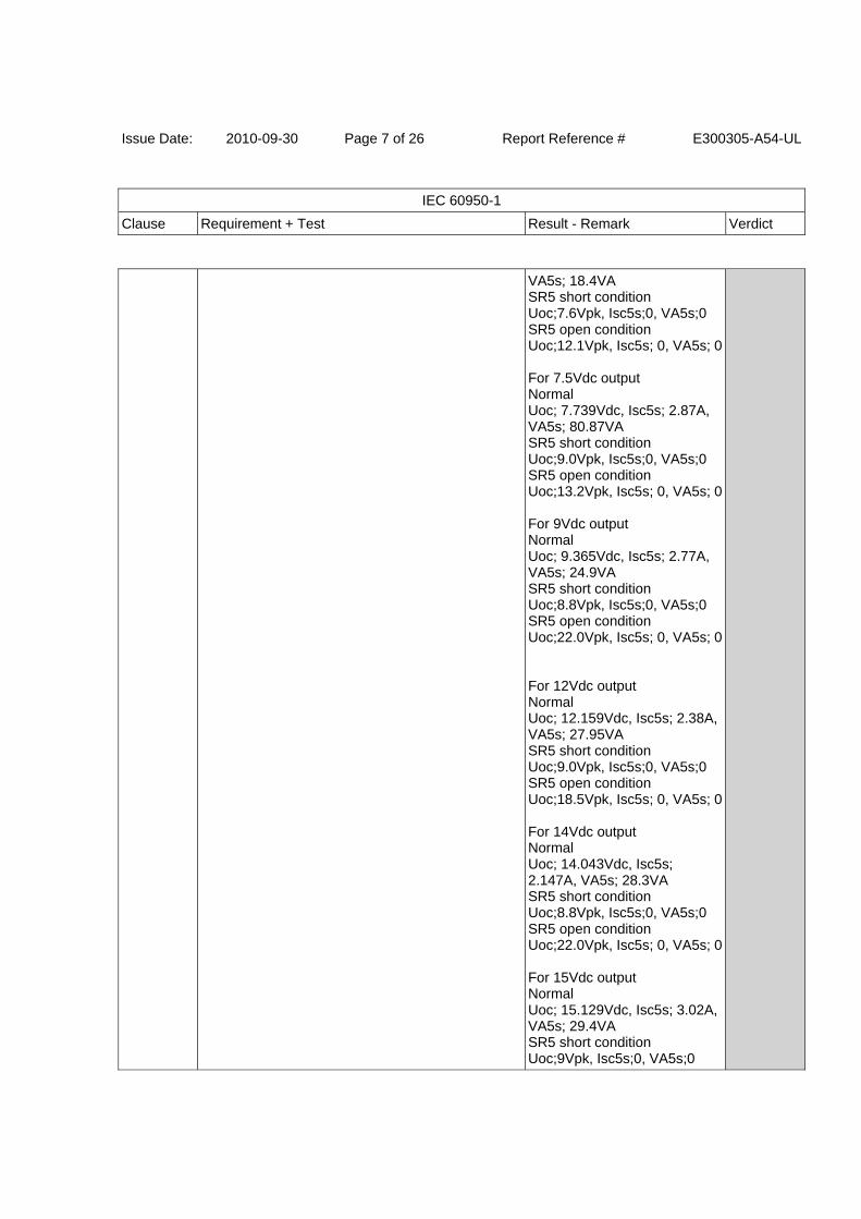
For 3.3Vdc output Normal Uoc; 3.559Vdc, Isc5s; 4.15A, VA5s; 12.5VA SR5 short condition Uoc;4.5Vpk, Isc5s;0, VA5s;0 SR5 open condition Uoc;7.0Vpk, Isc5s; 0, VA5s; 0 For 5Vdc output Normal Uoc; 5.201Vdc, Isc5s; 4.09A, VA5s; 19.15VA SR5 short condition Uoc;6.5Vpk, Isc5s;0, VA5s;0 SR5 open condition Uoc;10.8Vpk, Isc5s; 0, VA5s; 0 For 6Vdc output Normal Uoc; 6.191Vdc, Isc5s; 3.23A,
-
Issue Date: 2010-09-30 Page 7 of 26 Report Reference # E300305-A54-UL
IEC 60950-1
Clause Requirement + Test Result - Remark Verdict
VA5s; 18.4VA SR5 short condition Uoc;7.6Vpk, Isc5s;0, VA5s;0 SR5 open condition Uoc;12.1Vpk, Isc5s; 0, VA5s; 0 For 7.5Vdc output Normal Uoc; 7.739Vdc, Isc5s; 2.87A, VA5s; 80.87VA SR5 short condition Uoc;9.0Vpk, Isc5s;0, VA5s;0 SR5 open condition Uoc;13.2Vpk, Isc5s; 0, VA5s; 0 For 9Vdc output Normal Uoc; 9.365Vdc, Isc5s; 2.77A, VA5s; 24.9VA SR5 short condition Uoc;8.8Vpk, Isc5s;0, VA5s;0 SR5 open condition Uoc;22.0Vpk, Isc5s; 0, VA5s; 0 For 12Vdc output Normal Uoc; 12.159Vdc, Isc5s; 2.38A, VA5s; 27.95VA SR5 short condition Uoc;9.0Vpk, Isc5s;0, VA5s;0 SR5 open condition Uoc;18.5Vpk, Isc5s; 0, VA5s; 0 For 14Vdc output Normal Uoc; 14.043Vdc, Isc5s; 2.147A, VA5s; 28.3VA SR5 short condition Uoc;8.8Vpk, Isc5s;0, VA5s;0 SR5 open condition Uoc;22.0Vpk, Isc5s; 0, VA5s; 0 For 15Vdc output Normal Uoc; 15.129Vdc, Isc5s; 3.02A, VA5s; 29.4VA SR5 short condition Uoc;9Vpk, Isc5s;0, VA5s;0
Issue Date: 2010-09-30 Page 8 of 26 Report Reference # E300305-A54-UL
IEC 60950-1
Clause Requirement + Test Result - Remark Verdict
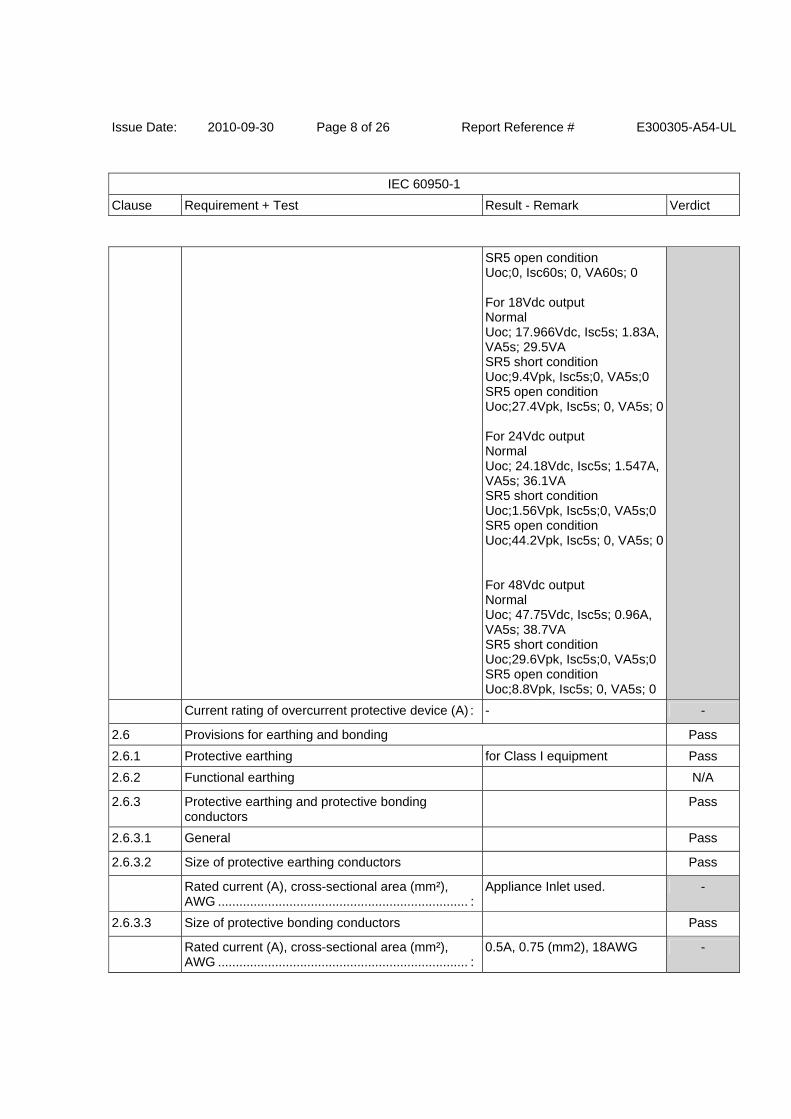
SR5 open condition Uoc;0, Isc60s; 0, VA60s; 0 For 18Vdc output Normal Uoc; 17.966Vdc, Isc5s; 1.83A, VA5s; 29.5VA SR5 short condition Uoc;9.4Vpk, Isc5s;0, VA5s;0 SR5 open condition Uoc;27.4Vpk, Isc5s; 0, VA5s; 0 For 24Vdc output Normal Uoc; 24.18Vdc, Isc5s; 1.547A, VA5s; 36.1VA SR5 short condition Uoc;1.56Vpk, Isc5s;0, VA5s;0SR5 open condition Uoc;44.2Vpk, Isc5s; 0, VA5s; 0 For 48Vdc output Normal Uoc; 47.75Vdc, Isc5s; 0.96A, VA5s; 38.7VA SR5 short condition Uoc;29.6Vpk, Isc5s;0, VA5s;0SR5 open condition Uoc;8.8Vpk, Isc5s; 0, VA5s; 0
Current rating of overcurrent protective device (A) : - -
2.6 Provisions for earthing and bonding Pass
2.6.1 Protective earthing for Class I equipment Pass
2.6.2 Functional earthing N/A
2.6.3 Protective earthing and protective bonding conductors
Pass
2.6.3.1 General Pass
2.6.3.2 Size of protective earthing conductors Pass
Rated current (A), cross-sectional area (mm²), AWG ...................................................................... :
Appliance Inlet used. -
2.6.3.3 Size of protective bonding conductors Pass
Rated current (A), cross-sectional area (mm²), AWG ...................................................................... :
0.5A, 0.75 (mm2), 18AWG -

Issue Date: 2010-09-30 Page 9 of 26 Report Reference # E300305-A54-UL
IEC 60950-1
Clause Requirement + Test Result - Remark Verdict
Protective current rating (A), cross-sectional area (mm²), AWG........................................................... :
- -
2.6.3.4 Resistance of earthing conductors and their terminations; resistance (ohm), voltage drop (V), test current (A), duration (min) ............................... :
0.016 ohm, 0.63 Vdrop(Appliance inlet GND pin to Molded Ground on PWB), 40 A, 2 minute.(for Class I equipment)
Pass
2.6.3.5 Colour of insulation ................................................ : Protective bonding conductor is green with yellow stripe.(for Class I equipment)
Pass
2.6.4 Terminals Pass
2.6.4.1 General Pass
2.6.4.2 Protective earthing and bonding terminals Pass
Rated current (A), type, nominal thread diameter (mm) ...................................................................... :
Appliance Inlet used. -
2.6.4.3 Separation of the protective earthing conductor from protective bonding conductors
N/A
2.6.5 Integrity of protective earthing Pass
2.6.5.1 Interconnection of equipment N/A
2.6.5.2 Components in protective earthing conductors and protective bonding conductors
No switches or fuses in earthing conductors.
Pass
2.6.5.3 Disconnection of protective earth Disconnection of the protective earth at one assembly removes connection of HAZARDOUS VOLTAGES from the other assemblies at the same time.(for Class I equipment)
Pass
2.6.5.4 Parts that can be removed by an operator It is not possible to disconnect earth without disconnecting mains.
Pass
2.6.5.5 Parts removed during servicing Connections to protective earthing cannot be removed unless hazardous voltage is removed from the part simultaneously.
Pass
2.6.5.6 Corrosion resistance N/A
2.6.5.7 Screws for protective bonding N/A
2.6.5.8 Reliance on telecommunication network or cable distribution system
N/A
Issue Date: 2010-09-30 Page 10 of 26 Report Reference # E300305-A54-UL
IEC 60950-1
Clause Requirement + Test Result - Remark Verdict
2.7 Overcurrent and earth fault protection in primary circuits Pass
2.7.1 Basic requirements Pass
Instructions when protection relies on building installation
N/A
2.7.2 Faults not covered in 5.3.7 N/A
2.7.3 Short-circuit backup protection Pass
2.7.4 Number and location of protective devices ........... : Two protective devices used. One for "LIVE" phase, the other for "Neutral" phase (optional).
Pass
2.7.5 Protection by several devices Pass
2.7.6 Warning to service personnel ................................ : No Service area N/A
2.8 Safety interlocks N/A
2.8.1 General principles N/A
2.8.2 Protection requirements N/A
2.8.3 Inadvertent reactivation N/A
2.8.4 Fail-safe operation N/A
2.8.5 Moving parts N/A
2.8.6 Overriding N/A
2.8.7 Switches and relays N/A
2.8.7.1 Contact gaps (mm) ................................................ : N/A
2.8.7.2 Overload test N/A
2.8.7.3 Endurance test N/A
2.8.7.4 Electric strength test N/A
2.8.8 Mechanical actuators N/A
2.9 Electrical insulation Pass
2.9.1 Properties of insulating materials Natural rubber, asbestos or hygroscopic material is not used.
Pass
2.9.2 Humidity conditioning Pass
Relative humidity (%), temperature (°C) ................ : 93%, 30 degree C. -
2.9.3 Grade of insulation Insulation materials comply with sub-clauses 2.10, 4.5 and 5.2.
Pass
Issue Date: 2010-09-30 Page 11 of 26 Report Reference # E300305-A54-UL
IEC 60950-1
Clause Requirement + Test Result - Remark Verdict
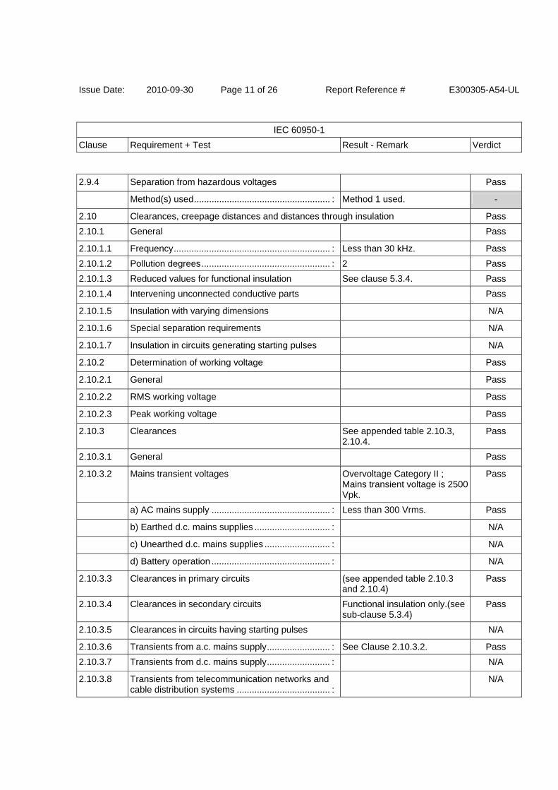
2.9.4 Separation from hazardous voltages Pass
Method(s) used ...................................................... : Method 1 used. -
2.10 Clearances, creepage distances and distances through insulation Pass
2.10.1 General Pass
2.10.1.1 Frequency .............................................................. : Less than 30 kHz. Pass
2.10.1.2 Pollution degrees ................................................... : 2 Pass
2.10.1.3 Reduced values for functional insulation See clause 5.3.4. Pass
2.10.1.4 Intervening unconnected conductive parts Pass
2.10.1.5 Insulation with varying dimensions N/A
2.10.1.6 Special separation requirements N/A
2.10.1.7 Insulation in circuits generating starting pulses N/A
2.10.2 Determination of working voltage Pass
2.10.2.1 General Pass
2.10.2.2 RMS working voltage Pass
2.10.2.3 Peak working voltage Pass
2.10.3 Clearances See appended table 2.10.3, 2.10.4.
Pass
2.10.3.1 General Pass
2.10.3.2 Mains transient voltages Overvoltage Category II ; Mains transient voltage is 2500 Vpk.
Pass
a) AC mains supply ............................................... : Less than 300 Vrms. Pass
b) Earthed d.c. mains supplies .............................. : N/A
c) Unearthed d.c. mains supplies .......................... : N/A
d) Battery operation ............................................... : N/A
2.10.3.3 Clearances in primary circuits (see appended table 2.10.3 and 2.10.4)
Pass
2.10.3.4 Clearances in secondary circuits Functional insulation only.(see sub-clause 5.3.4)
Pass
2.10.3.5 Clearances in circuits having starting pulses N/A
2.10.3.6 Transients from a.c. mains supply ......................... : See Clause 2.10.3.2. Pass
2.10.3.7 Transients from d.c. mains supply ......................... : N/A
2.10.3.8 Transients from telecommunication networks and cable distribution systems ..................................... :
N/A
Issue Date: 2010-09-30 Page 12 of 26 Report Reference # E300305-A54-UL
IEC 60950-1
Clause Requirement + Test Result - Remark Verdict
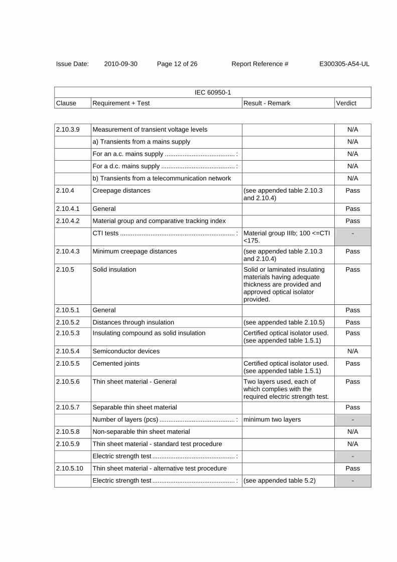
2.10.3.9 Measurement of transient voltage levels N/A
a) Transients from a mains supply N/A
For an a.c. mains supply ....................................... : N/A
For a d.c. mains supply ......................................... : N/A
b) Transients from a telecommunication network N/A
2.10.4 Creepage distances (see appended table 2.10.3 and 2.10.4)
Pass
2.10.4.1 General Pass
2.10.4.2 Material group and comparative tracking index Pass
CTI tests ................................................................ : Material group IIIb; 100 <=CTI <175.
-
2.10.4.3 Minimum creepage distances (see appended table 2.10.3 and 2.10.4)
Pass
2.10.5 Solid insulation Solid or laminated insulating materials having adequate thickness are provided and approved optical isolator provided.
Pass
2.10.5.1 General Pass
2.10.5.2 Distances through insulation (see appended table 2.10.5) Pass
2.10.5.3 Insulating compound as solid insulation Certified optical isolator used.(see appended table 1.5.1)
Pass
2.10.5.4 Semiconductor devices N/A
2.10.5.5 Cemented joints Certified optical isolator used.(see appended table 1.5.1)
Pass
2.10.5.6 Thin sheet material - General Two layers used, each of which complies with the required electric strength test.
Pass
2.10.5.7 Separable thin sheet material Pass
Number of layers (pcs) .......................................... : minimum two layers -
2.10.5.8 Non-separable thin sheet material N/A
2.10.5.9 Thin sheet material - standard test procedure N/A
Electric strength test .............................................. : -
2.10.5.10 Thin sheet material - alternative test procedure Pass
Electric strength test .............................................. : (see appended table 5.2) -
Issue Date: 2010-09-30 Page 13 of 26 Report Reference # E300305-A54-UL
IEC 60950-1
Clause Requirement + Test Result - Remark Verdict
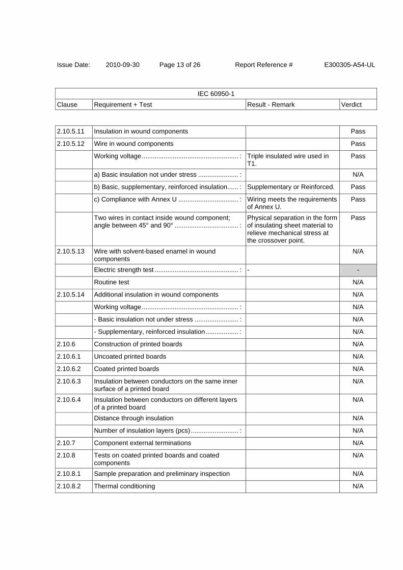
2.10.5.11 Insulation in wound components Pass
2.10.5.12 Wire in wound components Pass
Working voltage ..................................................... : Triple insulated wire used in T1.
Pass
a) Basic insulation not under stress ...................... : N/A
b) Basic, supplementary, reinforced insulation ...... : Supplementary or Reinforced. Pass
c) Compliance with Annex U ................................. : Wiring meets the requirements of Annex U.
Pass
Two wires in contact inside wound component; angle between 45° and 90° ................................... :
Physical separation in the form of insulating sheet material to relieve mechanical stress at the crossover point.
Pass
2.10.5.13 Wire with solvent-based enamel in wound components
N/A
Electric strength test .............................................. : - -
Routine test N/A
2.10.5.14 Additional insulation in wound components N/A
Working voltage ..................................................... : N/A
- Basic insulation not under stress ........................ : N/A
- Supplementary, reinforced insulation .................. : N/A
2.10.6 Construction of printed boards N/A
2.10.6.1 Uncoated printed boards N/A
2.10.6.2 Coated printed boards N/A
2.10.6.3 Insulation between conductors on the same inner surface of a printed board
N/A
2.10.6.4 Insulation between conductors on different layers of a printed board
N/A
Distance through insulation N/A
Number of insulation layers (pcs) .......................... : N/A
2.10.7 Component external terminations N/A
2.10.8 Tests on coated printed boards and coated components
N/A
2.10.8.1 Sample preparation and preliminary inspection N/A
2.10.8.2 Thermal conditioning N/A
Issue Date: 2010-09-30 Page 14 of 26 Report Reference # E300305-A54-UL
IEC 60950-1
Clause Requirement + Test Result - Remark Verdict
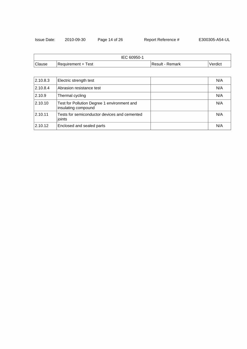
2.10.8.3 Electric strength test N/A
2.10.8.4 Abrasion resistance test N/A
2.10.9 Thermal cycling N/A
2.10.10 Test for Pollution Degree 1 environment and insulating compound
N/A
2.10.11 Tests for semiconductor devices and cemented joints
N/A
2.10.12 Enclosed and sealed parts N/A
Issue Date: 2010-09-30 Page 15 of 26 Report Reference # E300305-A54-UL
IEC 60950-1
Clause Requirement + Test Result - Remark Verdict
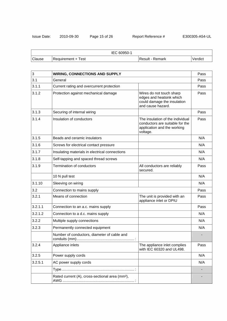
3 WIRING, CONNECTIONS AND SUPPLY Pass
3.1 General Pass
3.1.1 Current rating and overcurrent protection Pass
3.1.2 Protection against mechanical damage Wires do not touch sharp edges and heatsink which could damage the insulation and cause hazard.
Pass
3.1.3 Securing of internal wiring Pass
3.1.4 Insulation of conductors The insulation of the individual conductors are suitable for the application and the working voltage.
Pass
3.1.5 Beads and ceramic insulators N/A
3.1.6 Screws for electrical contact pressure N/A
3.1.7 Insulating materials in electrical connections N/A
3.1.8 Self-tapping and spaced thread screws N/A
3.1.9 Termination of conductors All conductors are reliably secured.
Pass
10 N pull test N/A
3.1.10 Sleeving on wiring N/A
3.2 Connection to mains supply Pass
3.2.1 Means of connection The unit is provided with an appliance inlet or DPIU
Pass
3.2.1.1 Connection to an a.c. mains supply Pass
3.2.1.2 Connection to a d.c. mains supply N/A
3.2.2 Multiple supply connections N/A
3.2.3 Permanently connected equipment N/A
Number of conductors, diameter of cable and conduits (mm) ........................................................ :
-
3.2.4 Appliance inlets The appliance inlet complies with IEC 60320 and UL498.
Pass
3.2.5 Power supply cords N/A
3.2.5.1 AC power supply cords N/A
Type ....................................................................... : -
Rated current (A), cross-sectional area (mm²), AWG ...................................................................... :
-
Issue Date: 2010-09-30 Page 16 of 26 Report Reference # E300305-A54-UL
IEC 60950-1
Clause Requirement + Test Result - Remark Verdict
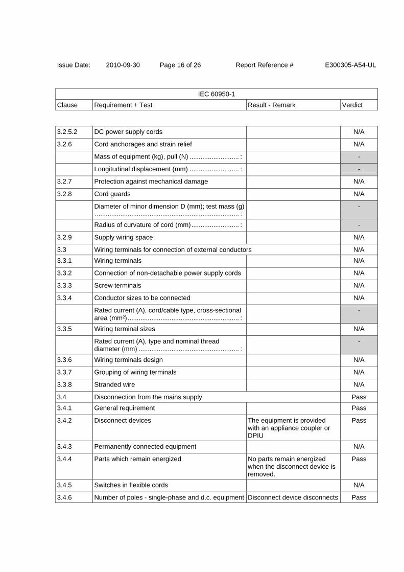
3.2.5.2 DC power supply cords N/A
3.2.6 Cord anchorages and strain relief N/A
Mass of equipment (kg), pull (N) ........................... : -
Longitudinal displacement (mm) ........................... : -
3.2.7 Protection against mechanical damage N/A
3.2.8 Cord guards N/A
Diameter of minor dimension D (mm); test mass (g) ............................................................................... :
-
Radius of curvature of cord (mm) .......................... : -
3.2.9 Supply wiring space N/A
3.3 Wiring terminals for connection of external conductors N/A
3.3.1 Wiring terminals N/A
3.3.2 Connection of non-detachable power supply cords N/A
3.3.3 Screw terminals N/A
3.3.4 Conductor sizes to be connected N/A
Rated current (A), cord/cable type, cross-sectional area (mm²) ............................................................. :
-
3.3.5 Wiring terminal sizes N/A
Rated current (A), type and nominal thread diameter (mm) ....................................................... :
-
3.3.6 Wiring terminals design N/A
3.3.7 Grouping of wiring terminals N/A
3.3.8 Stranded wire N/A
3.4 Disconnection from the mains supply Pass
3.4.1 General requirement Pass
3.4.2 Disconnect devices The equipment is provided with an appliance coupler or DPIU
Pass
3.4.3 Permanently connected equipment N/A
3.4.4 Parts which remain energized No parts remain energized when the disconnect device is removed.
Pass
3.4.5 Switches in flexible cords N/A
3.4.6 Number of poles - single-phase and d.c. equipment Disconnect device disconnects Pass
Issue Date: 2010-09-30 Page 17 of 26 Report Reference # E300305-A54-UL
IEC 60950-1
Clause Requirement + Test Result - Remark Verdict
all poles simultaneously.
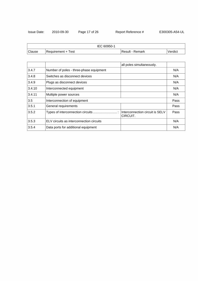
3.4.7 Number of poles - three-phase equipment N/A
3.4.8 Switches as disconnect devices N/A
3.4.9 Plugs as disconnect devices N/A
3.4.10 Interconnected equipment N/A
3.4.11 Multiple power sources N/A
3.5 Interconnection of equipment Pass
3.5.1 General requirements Pass
3.5.2 Types of interconnection circuits ........................... : Interconnection circuit is SELV CIRCUIT.
Pass
3.5.3 ELV circuits as interconnection circuits N/A
3.5.4 Data ports for additional equipment N/A
Issue Date: 2010-09-30 Page 18 of 26 Report Reference # E300305-A54-UL
IEC 60950-1
Clause Requirement + Test Result - Remark Verdict
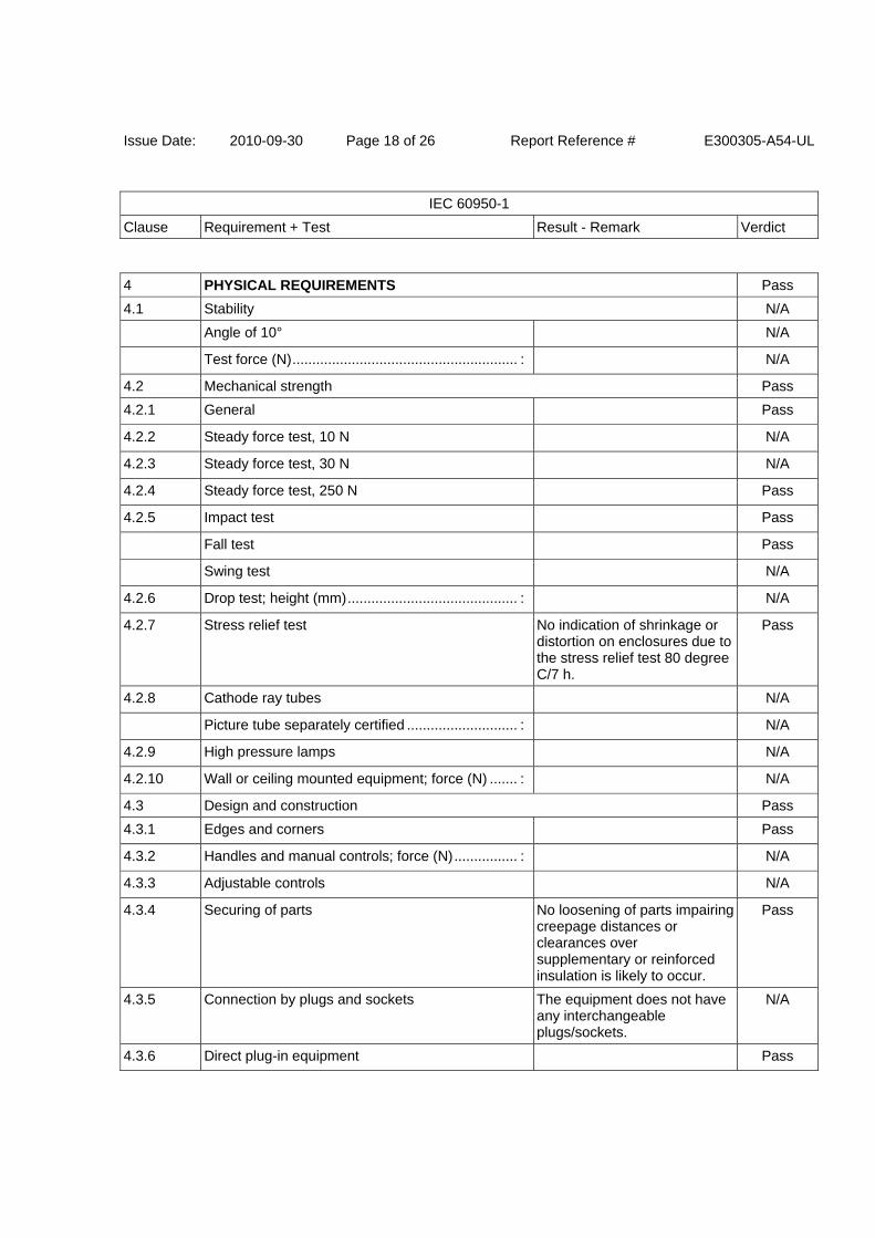
4 PHYSICAL REQUIREMENTS Pass
4.1 Stability N/A
Angle of 10° N/A
Test force (N) ......................................................... : N/A
4.2 Mechanical strength Pass
4.2.1 General Pass
4.2.2 Steady force test, 10 N N/A
4.2.3 Steady force test, 30 N N/A
4.2.4 Steady force test, 250 N Pass
4.2.5 Impact test Pass
Fall test Pass
Swing test N/A
4.2.6 Drop test; height (mm) ........................................... : N/A
4.2.7 Stress relief test No indication of shrinkage or distortion on enclosures due to the stress relief test 80 degree C/7 h.
Pass
4.2.8 Cathode ray tubes N/A
Picture tube separately certified ............................ : N/A
4.2.9 High pressure lamps N/A
4.2.10 Wall or ceiling mounted equipment; force (N) ....... : N/A
4.3 Design and construction Pass
4.3.1 Edges and corners Pass
4.3.2 Handles and manual controls; force (N) ................ : N/A
4.3.3 Adjustable controls N/A
4.3.4 Securing of parts No loosening of parts impairing creepage distances or clearances over supplementary or reinforced insulation is likely to occur.
Pass
4.3.5 Connection by plugs and sockets The equipment does not have any interchangeable plugs/sockets.
N/A
4.3.6 Direct plug-in equipment Pass
Issue Date: 2010-09-30 Page 19 of 26 Report Reference # E300305-A54-UL
IEC 60950-1
Clause Requirement + Test Result - Remark Verdict
Torque ................................................................... : - Pass
Compliance with the relevant mains plug standard: - Pass
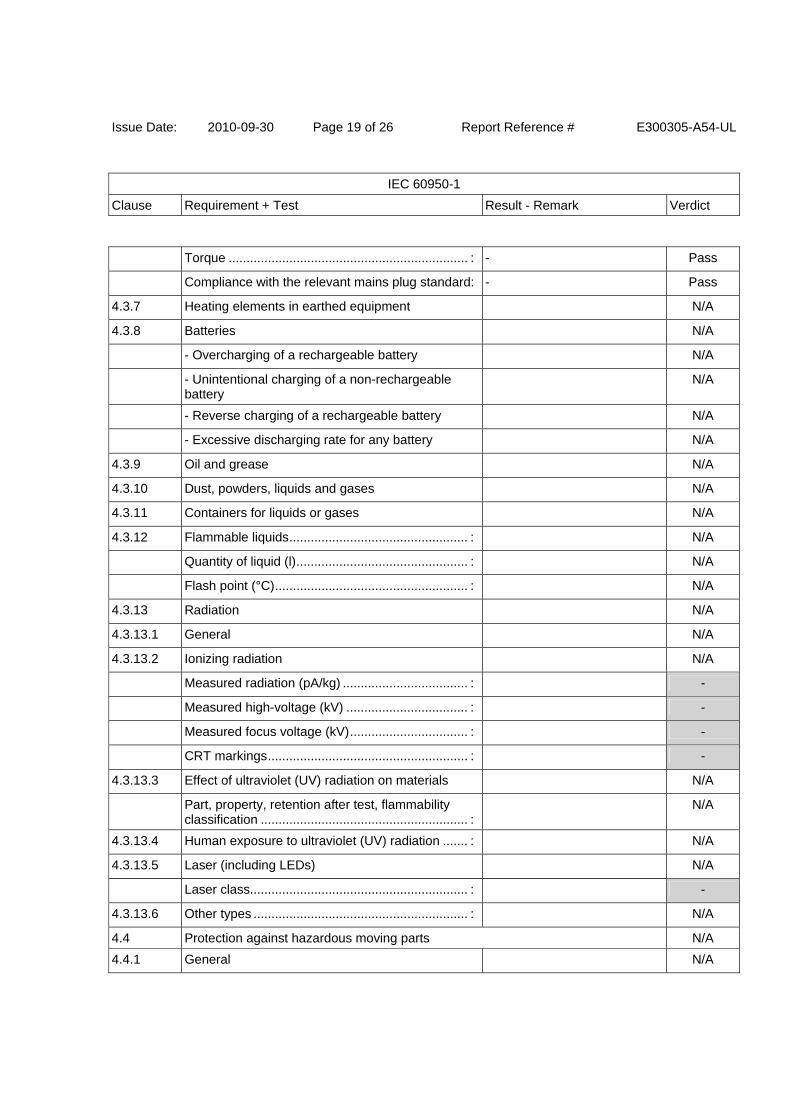
4.3.7 Heating elements in earthed equipment N/A
4.3.8 Batteries N/A
- Overcharging of a rechargeable battery N/A
- Unintentional charging of a non-rechargeable battery
N/A
- Reverse charging of a rechargeable battery N/A
- Excessive discharging rate for any battery N/A
4.3.9 Oil and grease N/A
4.3.10 Dust, powders, liquids and gases N/A
4.3.11 Containers for liquids or gases N/A
4.3.12 Flammable liquids .................................................. : N/A
Quantity of liquid (l) ................................................ : N/A
Flash point (°C) ...................................................... : N/A
4.3.13 Radiation N/A
4.3.13.1 General N/A
4.3.13.2 Ionizing radiation N/A
Measured radiation (pA/kg) ................................... : -
Measured high-voltage (kV) .................................. : -
Measured focus voltage (kV) ................................. : -
CRT markings ........................................................ : -
4.3.13.3 Effect of ultraviolet (UV) radiation on materials N/A
Part, property, retention after test, flammability classification .......................................................... :
N/A
4.3.13.4 Human exposure to ultraviolet (UV) radiation ....... : N/A
4.3.13.5 Laser (including LEDs) N/A
Laser class............................................................. : -
4.3.13.6 Other types ............................................................ : N/A
4.4 Protection against hazardous moving parts N/A
4.4.1 General N/A
Issue Date: 2010-09-30 Page 20 of 26 Report Reference # E300305-A54-UL
IEC 60950-1
Clause Requirement + Test Result - Remark Verdict
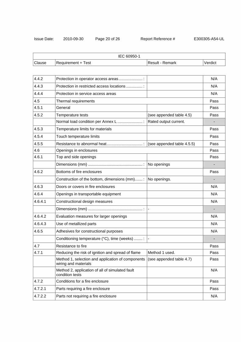
4.4.2 Protection in operator access areas ...................... : N/A
4.4.3 Protection in restricted access locations ............... : N/A
4.4.4 Protection in service access areas N/A
4.5 Thermal requirements Pass
4.5.1 General Pass
4.5.2 Temperature tests (see appended table 4.5) Pass
Normal load condition per Annex L ....................... : Rated output current. -
4.5.3 Temperature limits for materials Pass
4.5.4 Touch temperature limits Pass
4.5.5 Resistance to abnormal heat ................................. : (see appended table 4.5.5) Pass
4.6 Openings in enclosures Pass
4.6.1 Top and side openings Pass
Dimensions (mm) .................................................. : No openings -
4.6.2 Bottoms of fire enclosures Pass
Construction of the bottom, dimensions (mm) ....... : No openings. -
4.6.3 Doors or covers in fire enclosures N/A
4.6.4 Openings in transportable equipment N/A
4.6.4.1 Constructional design measures N/A
Dimensions (mm) .................................................. : - -
4.6.4.2 Evaluation measures for larger openings N/A
4.6.4.3 Use of metallized parts N/A
4.6.5 Adhesives for constructional purposes N/A
Conditioning temperature (°C), time (weeks) ........ : - -
4.7 Resistance to fire Pass
4.7.1 Reducing the risk of ignition and spread of flame Method 1 used. Pass
Method 1, selection and application of components wiring and materials
(see appended table 4.7) Pass
Method 2, application of all of simulated fault condition tests
N/A
4.7.2 Conditions for a fire enclosure Pass
4.7.2.1 Parts requiring a fire enclosure Pass
4.7.2.2 Parts not requiring a fire enclosure N/A
Issue Date: 2010-09-30 Page 21 of 26 Report Reference # E300305-A54-UL
IEC 60950-1
Clause Requirement + Test Result - Remark Verdict
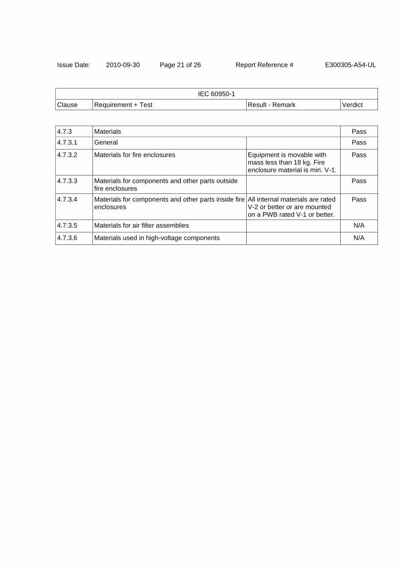
4.7.3 Materials Pass
4.7.3.1 General Pass
4.7.3.2 Materials for fire enclosures Equipment is movable with mass less than 18 kg. Fire enclosure material is min. V-1.
Pass
4.7.3.3 Materials for components and other parts outside fire enclosures
Pass
4.7.3.4 Materials for components and other parts inside fire enclosures
All internal materials are rated V-2 or better or are mounted on a PWB rated V-1 or better.
Pass
4.7.3.5 Materials for air filter assemblies N/A
4.7.3.6 Materials used in high-voltage components N/A
Issue Date: 2010-09-30 Page 22 of 26 Report Reference # E300305-A54-UL
IEC 60950-1
Clause Requirement + Test Result - Remark Verdict
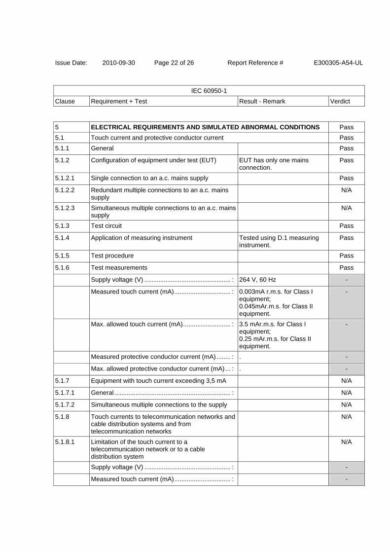
5 ELECTRICAL REQUIREMENTS AND SIMULATED ABNORMAL CONDITIONS Pass
5.1 Touch current and protective conductor current Pass
5.1.1 General Pass
5.1.2 Configuration of equipment under test (EUT) EUT has only one mains connection.
Pass
5.1.2.1 Single connection to an a.c. mains supply Pass
5.1.2.2 Redundant multiple connections to an a.c. mains supply
N/A
5.1.2.3 Simultaneous multiple connections to an a.c. mains supply
N/A
5.1.3 Test circuit Pass
5.1.4 Application of measuring instrument Tested using D.1 measuring instrument.
Pass
5.1.5 Test procedure Pass
5.1.6 Test measurements Pass
Supply voltage (V) ................................................. : 264 V, 60 Hz -
Measured touch current (mA) ................................ : 0.003mA r.m.s. for Class I equipment; 0.045mAr.m.s. for Class II equipment.
-
Max. allowed touch current (mA) ........................... : 3.5 mAr.m.s. for Class I equipment; 0.25 mAr.m.s. for Class II equipment.
-
Measured protective conductor current (mA) ........ : . -
Max. allowed protective conductor current (mA) ... : . -
5.1.7 Equipment with touch current exceeding 3,5 mA N/A
5.1.7.1 General .................................................................. : N/A
5.1.7.2 Simultaneous multiple connections to the supply N/A
5.1.8 Touch currents to telecommunication networks and cable distribution systems and from telecommunication networks
N/A
5.1.8.1 Limitation of the touch current to a telecommunication network or to a cable distribution system
N/A
Supply voltage (V) ................................................. : -
Measured touch current (mA) ................................ : -
Issue Date: 2010-09-30 Page 23 of 26 Report Reference # E300305-A54-UL
IEC 60950-1
Clause Requirement + Test Result - Remark Verdict
Max. allowed touch current (mA) ........................... : -
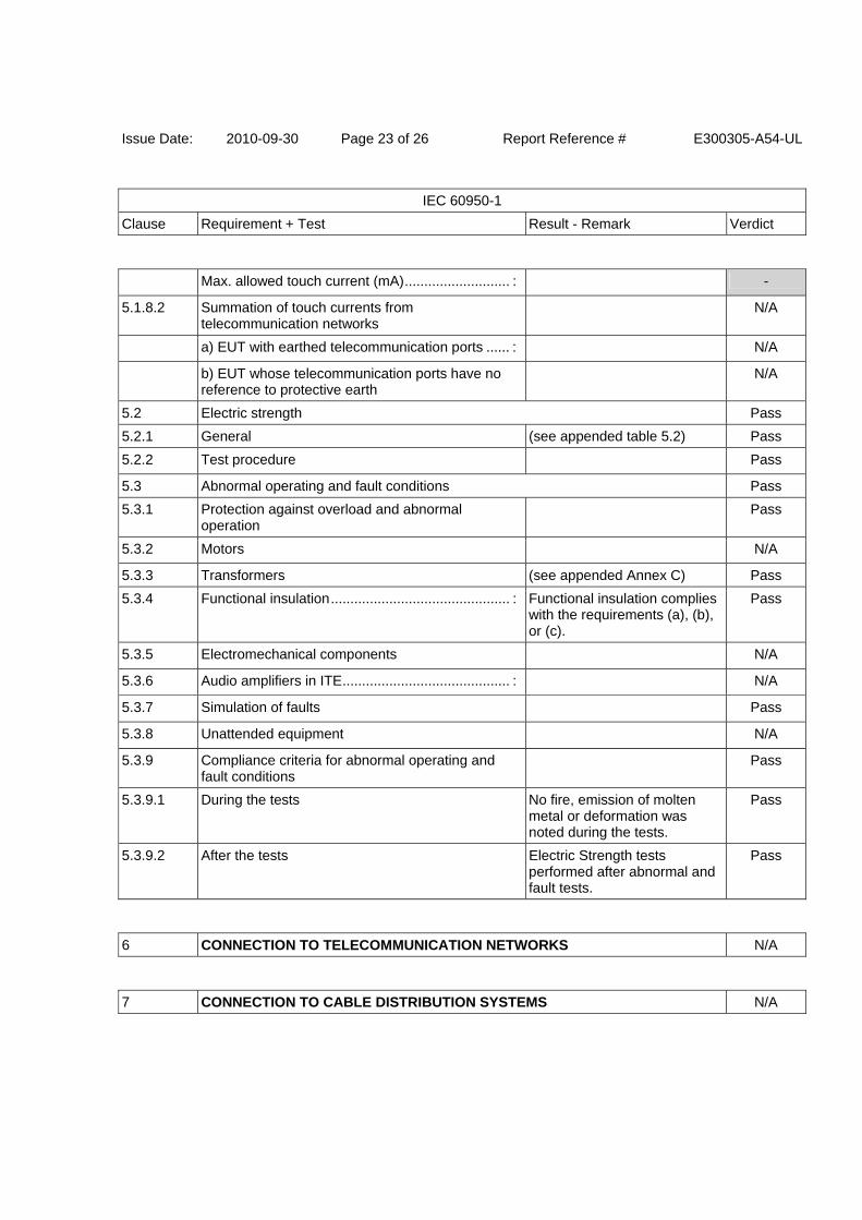
5.1.8.2 Summation of touch currents from telecommunication networks
N/A
a) EUT with earthed telecommunication ports ...... : N/A
b) EUT whose telecommunication ports have no reference to protective earth
N/A
5.2 Electric strength Pass
5.2.1 General (see appended table 5.2) Pass
5.2.2 Test procedure Pass
5.3 Abnormal operating and fault conditions Pass
5.3.1 Protection against overload and abnormal operation
Pass
5.3.2 Motors N/A
5.3.3 Transformers (see appended Annex C) Pass
5.3.4 Functional insulation .............................................. : Functional insulation complies with the requirements (a), (b), or (c).
Pass
5.3.5 Electromechanical components N/A
5.3.6 Audio amplifiers in ITE ........................................... : N/A
5.3.7 Simulation of faults Pass
5.3.8 Unattended equipment N/A
5.3.9 Compliance criteria for abnormal operating and fault conditions
Pass
5.3.9.1 During the tests No fire, emission of molten metal or deformation was noted during the tests.
Pass
5.3.9.2 After the tests Electric Strength tests performed after abnormal and fault tests.
Pass
6 CONNECTION TO TELECOMMUNICATION NETWORKS N/A
7 CONNECTION TO CABLE DISTRIBUTION SYSTEMS N/A
Issue Date: 2010-09-30 Page 24 of 26 Report Reference # E300305-A54-UL
IEC 60950-1
Clause Requirement + Test Result - Remark Verdict
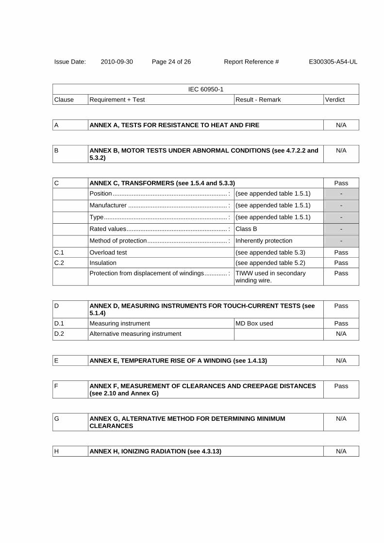
A ANNEX A, TESTS FOR RESISTANCE TO HEAT AND FIRE N/A
B ANNEX B, MOTOR TESTS UNDER ABNORMAL CONDITIONS (see 4.7.2.2 and 5.3.2)
N/A
C ANNEX C, TRANSFORMERS (see 1.5.4 and 5.3.3) Pass
Position .................................................................. : (see appended table 1.5.1) -
Manufacturer ......................................................... : (see appended table 1.5.1) -
Type ....................................................................... : (see appended table 1.5.1) -
Rated values .......................................................... : Class B -
Method of protection .............................................. : Inherently protection -
C.1 Overload test (see appended table 5.3) Pass
C.2 Insulation (see appended table 5.2) Pass
Protection from displacement of windings ............. : TIWW used in secondary winding wire.
Pass
D ANNEX D, MEASURING INSTRUMENTS FOR TOUCH-CURRENT TESTS (see 5.1.4)
Pass
D.1 Measuring instrument MD Box used Pass
D.2 Alternative measuring instrument N/A
E ANNEX E, TEMPERATURE RISE OF A WINDING (see 1.4.13) N/A
F ANNEX F, MEASUREMENT OF CLEARANCES AND CREEPAGE DISTANCES (see 2.10 and Annex G)
Pass
G ANNEX G, ALTERNATIVE METHOD FOR DETERMINING MINIMUM CLEARANCES
N/A
H ANNEX H, IONIZING RADIATION (see 4.3.13) N/A

Issue Date: 2010-09-30 Page 25 of 26 Report Reference # E300305-A54-UL
IEC 60950-1
Clause Requirement + Test Result - Remark Verdict
J ANNEX J, TABLE OF ELECTROCHEMICAL POTENTIALS (see 2.6.5.6) N/A
K ANNEX K, THERMAL CONTROLS (see 1.5.3 and 5.3.8) N/A
L ANNEX L, NORMAL LOAD CONDITIONS FOR SOME TYPES OF ELECTRICAL BUSINESS EQUIPMENT (see 1.2.2.1 and 4.5.2)
Pass
L.1 Typewriters N/A
L.2 Adding machines and cash registers N/A
L.3 Erasers N/A
L.4 Pencil sharpeners N/A
L.5 Duplicators and copy machines N/A
L.6 Motor-operated files N/A
L.7 Other business equipment AC/DC adapter, Rated output current.
Pass
M ANNEX M, CRITERIA FOR TELEPHONE RINGING SIGNALS (see 2.3.1) N/A
N ANNEX N, IMPULSE TEST GENERATORS (see 1.5.7.2, 1.5.7.3, 2.10.3.9, 6.2.2.1, 7.3.2, 7.4.3 and Clause G.5)
N/A
P ANNEX P, NORMATIVE REFERENCES Pass
Q ANNEX Q, Voltage dependent resistors (VDRs) (see 1.5.9.1) Pass
a) Preferred climatic categories ............................. : IEC 61051 and UL 1449 certified VDR used. (see appended table 1.5.1)
Pass
b) Maximum continuous voltage ............................ : Component rating is at least 120 % of the rated voltage of the equipment.
Pass
c) Pulse current ..................................................... : IEC 61051 and UL 1449 certified VDR used. (see appended table 1.5.1)
Pass
Issue Date: 2010-09-30 Page 26 of 26 Report Reference # E300305-A54-UL
IEC 60950-1
Clause Requirement + Test Result - Remark Verdict
R ANNEX R, EXAMPLES OF REQUIREMENTS FOR QUALITY CONTROL PROGRAMMES
N/A
S ANNEX S, PROCEDURE FOR IMPULSE TESTING (see 6.2.2.3) N/A
T ANNEX T, GUIDANCE ON PROTECTION AGAINST INGRESS OF WATER (see 1.1.2)
N/A
U ANNEX U, INSULATED WINDING WIRES FOR USE WITHOUT INTERLEAVED INSULATION (see 2.10.5.4)
Pass
............................................................................... : Triple insulated wire used in T1.
-
V ANNEX V, AC POWER DISTRIBUTION SYSTEMS (see 1.6.1) Pass
V.1 Introduction Pass
V.2 TN power distribution systems TN Pass
W ANNEX W, SUMMATION OF TOUCH CURRENTS N/A
X ANNEX X, MAXIMUM HEATING EFFECT IN TRANSFORMER TESTS (see clause C.1)
Pass
X.1 Determination of maximum input current Pass
X.2 Overload test procedure Pass
Y ANNEX Y, ULTRAVIOLET LIGHT CONDITIONING TEST (see 4.3.13.3) N/A
Z ANNEX Z, OVERVOLTAGE CATEGORIES (see 2.10.3.2 and Clause G.2) Pass
AA ANNEX AA, MANDREL TEST (see 2.10.5.8) N/A
Issue Date: 2010-09-30 Page 1 of 17 Report Reference # E300305-A54-UL
IEC 60950-1
Clause Requirement + Test Result - Remark Verdict
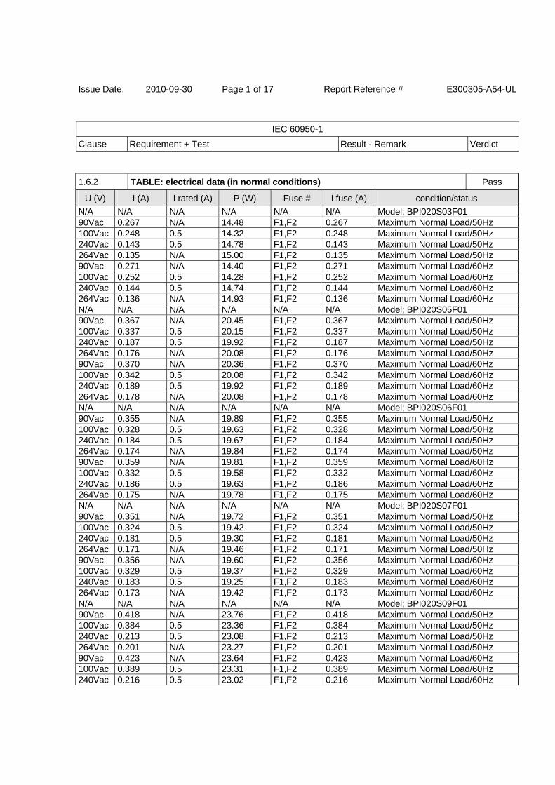
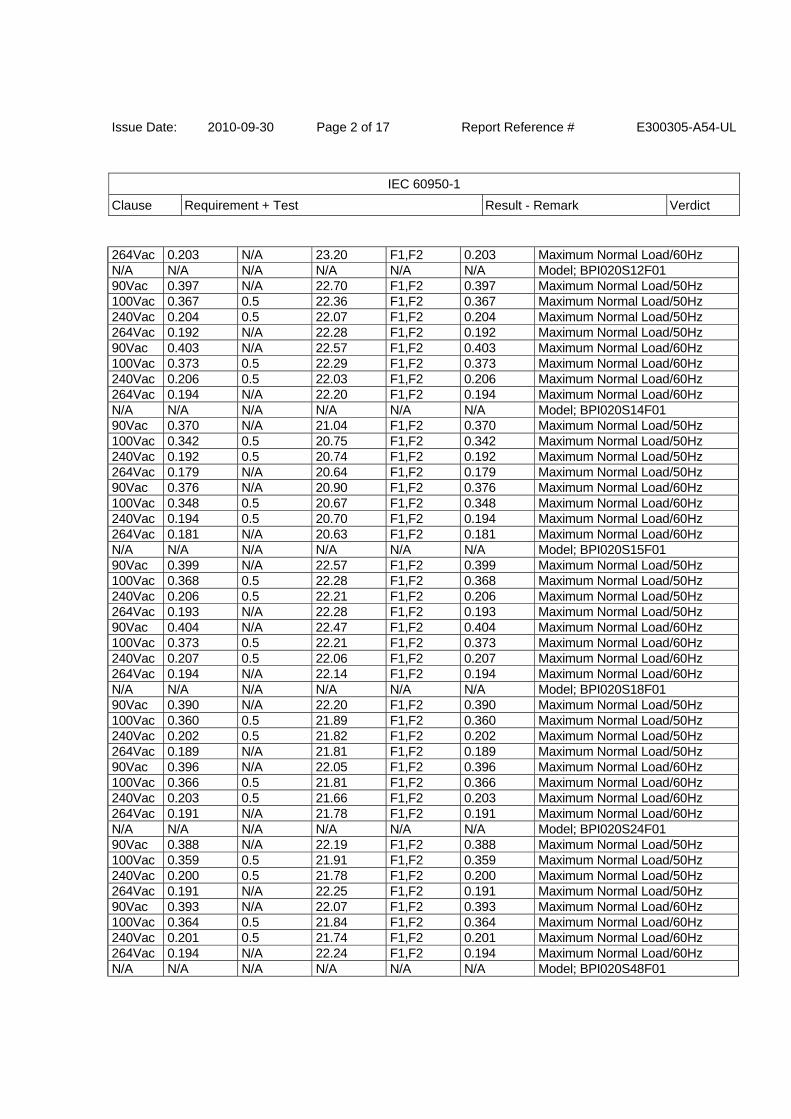
1.6.2 TABLE: electrical data (in normal conditions) Pass
U (V) I (A) I rated (A) P (W) Fuse # I fuse (A) condition/status
N/A N/A N/A N/A N/A N/A Model; BPI020S03F01 90Vac 0.267 N/A 14.48 F1,F2 0.267 Maximum Normal Load/50Hz 100Vac 0.248 0.5 14.32 F1,F2 0.248 Maximum Normal Load/50Hz 240Vac 0.143 0.5 14.78 F1,F2 0.143 Maximum Normal Load/50Hz 264Vac 0.135 N/A 15.00 F1,F2 0.135 Maximum Normal Load/50Hz 90Vac 0.271 N/A 14.40 F1,F2 0.271 Maximum Normal Load/60Hz 100Vac 0.252 0.5 14.28 F1,F2 0.252 Maximum Normal Load/60Hz 240Vac 0.144 0.5 14.74 F1,F2 0.144 Maximum Normal Load/60Hz 264Vac 0.136 N/A 14.93 F1,F2 0.136 Maximum Normal Load/60Hz N/A N/A N/A N/A N/A N/A Model; BPI020S05F01 90Vac 0.367 N/A 20.45 F1,F2 0.367 Maximum Normal Load/50Hz 100Vac 0.337 0.5 20.15 F1,F2 0.337 Maximum Normal Load/50Hz 240Vac 0.187 0.5 19.92 F1,F2 0.187 Maximum Normal Load/50Hz 264Vac 0.176 N/A 20.08 F1,F2 0.176 Maximum Normal Load/50Hz 90Vac 0.370 N/A 20.36 F1,F2 0.370 Maximum Normal Load/60Hz 100Vac 0.342 0.5 20.08 F1,F2 0.342 Maximum Normal Load/60Hz 240Vac 0.189 0.5 19.92 F1,F2 0.189 Maximum Normal Load/60Hz 264Vac 0.178 N/A 20.08 F1,F2 0.178 Maximum Normal Load/60Hz N/A N/A N/A N/A N/A N/A Model; BPI020S06F01 90Vac 0.355 N/A 19.89 F1,F2 0.355 Maximum Normal Load/50Hz 100Vac 0.328 0.5 19.63 F1,F2 0.328 Maximum Normal Load/50Hz 240Vac 0.184 0.5 19.67 F1,F2 0.184 Maximum Normal Load/50Hz 264Vac 0.174 N/A 19.84 F1,F2 0.174 Maximum Normal Load/50Hz 90Vac 0.359 N/A 19.81 F1,F2 0.359 Maximum Normal Load/60Hz 100Vac 0.332 0.5 19.58 F1,F2 0.332 Maximum Normal Load/60Hz 240Vac 0.186 0.5 19.63 F1,F2 0.186 Maximum Normal Load/60Hz 264Vac 0.175 N/A 19.78 F1,F2 0.175 Maximum Normal Load/60Hz N/A N/A N/A N/A N/A N/A Model; BPI020S07F01 90Vac 0.351 N/A 19.72 F1,F2 0.351 Maximum Normal Load/50Hz 100Vac 0.324 0.5 19.42 F1,F2 0.324 Maximum Normal Load/50Hz 240Vac 0.181 0.5 19.30 F1,F2 0.181 Maximum Normal Load/50Hz 264Vac 0.171 N/A 19.46 F1,F2 0.171 Maximum Normal Load/50Hz 90Vac 0.356 N/A 19.60 F1,F2 0.356 Maximum Normal Load/60Hz 100Vac 0.329 0.5 19.37 F1,F2 0.329 Maximum Normal Load/60Hz 240Vac 0.183 0.5 19.25 F1,F2 0.183 Maximum Normal Load/60Hz 264Vac 0.173 N/A 19.42 F1,F2 0.173 Maximum Normal Load/60Hz N/A N/A N/A N/A N/A N/A Model; BPI020S09F01 90Vac 0.418 N/A 23.76 F1,F2 0.418 Maximum Normal Load/50Hz 100Vac 0.384 0.5 23.36 F1,F2 0.384 Maximum Normal Load/50Hz 240Vac 0.213 0.5 23.08 F1,F2 0.213 Maximum Normal Load/50Hz 264Vac 0.201 N/A 23.27 F1,F2 0.201 Maximum Normal Load/50Hz 90Vac 0.423 N/A 23.64 F1,F2 0.423 Maximum Normal Load/60Hz 100Vac 0.389 0.5 23.31 F1,F2 0.389 Maximum Normal Load/60Hz 240Vac 0.216 0.5 23.02 F1,F2 0.216 Maximum Normal Load/60Hz
Issue Date: 2010-09-30 Page 2 of 17 Report Reference # E300305-A54-UL
IEC 60950-1
Clause Requirement + Test Result - Remark Verdict
264Vac 0.203 N/A 23.20 F1,F2 0.203 Maximum Normal Load/60Hz N/A N/A N/A N/A N/A N/A Model; BPI020S12F01 90Vac 0.397 N/A 22.70 F1,F2 0.397 Maximum Normal Load/50Hz 100Vac 0.367 0.5 22.36 F1,F2 0.367 Maximum Normal Load/50Hz 240Vac 0.204 0.5 22.07 F1,F2 0.204 Maximum Normal Load/50Hz 264Vac 0.192 N/A 22.28 F1,F2 0.192 Maximum Normal Load/50Hz 90Vac 0.403 N/A 22.57 F1,F2 0.403 Maximum Normal Load/60Hz 100Vac 0.373 0.5 22.29 F1,F2 0.373 Maximum Normal Load/60Hz 240Vac 0.206 0.5 22.03 F1,F2 0.206 Maximum Normal Load/60Hz 264Vac 0.194 N/A 22.20 F1,F2 0.194 Maximum Normal Load/60Hz N/A N/A N/A N/A N/A N/A Model; BPI020S14F01 90Vac 0.370 N/A 21.04 F1,F2 0.370 Maximum Normal Load/50Hz 100Vac 0.342 0.5 20.75 F1,F2 0.342 Maximum Normal Load/50Hz 240Vac 0.192 0.5 20.74 F1,F2 0.192 Maximum Normal Load/50Hz 264Vac 0.179 N/A 20.64 F1,F2 0.179 Maximum Normal Load/50Hz 90Vac 0.376 N/A 20.90 F1,F2 0.376 Maximum Normal Load/60Hz 100Vac 0.348 0.5 20.67 F1,F2 0.348 Maximum Normal Load/60Hz 240Vac 0.194 0.5 20.70 F1,F2 0.194 Maximum Normal Load/60Hz 264Vac 0.181 N/A 20.63 F1,F2 0.181 Maximum Normal Load/60Hz N/A N/A N/A N/A N/A N/A Model; BPI020S15F01 90Vac 0.399 N/A 22.57 F1,F2 0.399 Maximum Normal Load/50Hz 100Vac 0.368 0.5 22.28 F1,F2 0.368 Maximum Normal Load/50Hz 240Vac 0.206 0.5 22.21 F1,F2 0.206 Maximum Normal Load/50Hz 264Vac 0.193 N/A 22.28 F1,F2 0.193 Maximum Normal Load/50Hz 90Vac 0.404 N/A 22.47 F1,F2 0.404 Maximum Normal Load/60Hz 100Vac 0.373 0.5 22.21 F1,F2 0.373 Maximum Normal Load/60Hz 240Vac 0.207 0.5 22.06 F1,F2 0.207 Maximum Normal Load/60Hz 264Vac 0.194 N/A 22.14 F1,F2 0.194 Maximum Normal Load/60Hz N/A N/A N/A N/A N/A N/A Model; BPI020S18F01 90Vac 0.390 N/A 22.20 F1,F2 0.390 Maximum Normal Load/50Hz 100Vac 0.360 0.5 21.89 F1,F2 0.360 Maximum Normal Load/50Hz 240Vac 0.202 0.5 21.82 F1,F2 0.202 Maximum Normal Load/50Hz 264Vac 0.189 N/A 21.81 F1,F2 0.189 Maximum Normal Load/50Hz 90Vac 0.396 N/A 22.05 F1,F2 0.396 Maximum Normal Load/60Hz 100Vac 0.366 0.5 21.81 F1,F2 0.366 Maximum Normal Load/60Hz 240Vac 0.203 0.5 21.66 F1,F2 0.203 Maximum Normal Load/60Hz 264Vac 0.191 N/A 21.78 F1,F2 0.191 Maximum Normal Load/60Hz N/A N/A N/A N/A N/A N/A Model; BPI020S24F01 90Vac 0.388 N/A 22.19 F1,F2 0.388 Maximum Normal Load/50Hz 100Vac 0.359 0.5 21.91 F1,F2 0.359 Maximum Normal Load/50Hz 240Vac 0.200 0.5 21.78 F1,F2 0.200 Maximum Normal Load/50Hz 264Vac 0.191 N/A 22.25 F1,F2 0.191 Maximum Normal Load/50Hz 90Vac 0.393 N/A 22.07 F1,F2 0.393 Maximum Normal Load/60Hz 100Vac 0.364 0.5 21.84 F1,F2 0.364 Maximum Normal Load/60Hz 240Vac 0.201 0.5 21.74 F1,F2 0.201 Maximum Normal Load/60Hz 264Vac 0.194 N/A 22.24 F1,F2 0.194 Maximum Normal Load/60Hz N/A N/A N/A N/A N/A N/A Model; BPI020S48F01
Issue Date: 2010-09-30 Page 3 of 17 Report Reference # E300305-A54-UL
IEC 60950-1
Clause Requirement + Test Result - Remark Verdict
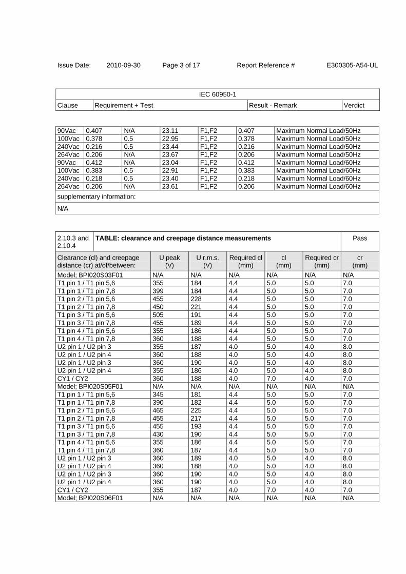
90Vac 0.407 N/A 23.11 F1,F2 0.407 Maximum Normal Load/50Hz 100Vac 0.378 0.5 22.95 F1,F2 0.378 Maximum Normal Load/50Hz 240Vac 0.216 0.5 23.44 F1,F2 0.216 Maximum Normal Load/50Hz 264Vac 0.206 N/A 23.67 F1,F2 0.206 Maximum Normal Load/50Hz 90Vac 0.412 N/A 23.04 F1,F2 0.412 Maximum Normal Load/60Hz 100Vac 0.383 0.5 22.91 F1,F2 0.383 Maximum Normal Load/60Hz 240Vac 0.218 0.5 23.40 F1,F2 0.218 Maximum Normal Load/60Hz 264Vac 0.206 N/A 23.61 F1,F2 0.206 Maximum Normal Load/60Hz
supplementary information:
N/A
2.10.3 and 2.10.4
TABLE: clearance and creepage distance measurements Pass
Clearance (cl) and creepage distance (cr) at/of/between:
U peak (V)
U r.m.s. (V)
Required cl(mm)
cl (mm)
Required cr(mm)
cr (mm)
Model; BPI020S03F01 N/A N/A N/A N/A N/A N/A T1 pin 1 / T1 pin 5,6 355 184 4.4 5.0 5.0 7.0 T1 pin 1 / T1 pin 7,8 399 184 4.4 5.0 5.0 7.0 T1 pin 2 / T1 pin 5,6 455 228 4.4 5.0 5.0 7.0 T1 pin 2 / T1 pin 7,8 450 221 4.4 5.0 5.0 7.0 T1 pin 3 / T1 pin 5,6 505 191 4.4 5.0 5.0 7.0 T1 pin 3 / T1 pin 7,8 455 189 4.4 5.0 5.0 7.0 T1 pin 4 / T1 pin 5,6 355 186 4.4 5.0 5.0 7.0 T1 pin 4 / T1 pin 7,8 360 188 4.4 5.0 5.0 7.0 U2 pin 1 / U2 pin 3 355 187 4.0 5.0 4.0 8.0 U2 pin 1 / U2 pin 4 360 188 4.0 5.0 4.0 8.0 U2 pin 1 / U2 pin 3 360 190 4.0 5.0 4.0 8.0 U2 pin 1 / U2 pin 4 355 186 4.0 5.0 4.0 8.0 CY1 / CY2 360 188 4.0 7.0 4.0 7.0 Model; BPI020S05F01 N/A N/A N/A N/A N/A N/A T1 pin 1 / T1 pin 5,6 345 181 4.4 5.0 5.0 7.0 T1 pin 1 / T1 pin 7,8 390 182 4.4 5.0 5.0 7.0 T1 pin 2 / T1 pin 5,6 465 225 4.4 5.0 5.0 7.0 T1 pin 2 / T1 pin 7,8 455 217 4.4 5.0 5.0 7.0 T1 pin 3 / T1 pin 5,6 455 193 4.4 5.0 5.0 7.0 T1 pin 3 / T1 pin 7,8 430 190 4.4 5.0 5.0 7.0 T1 pin 4 / T1 pin 5,6 355 186 4.4 5.0 5.0 7.0 T1 pin 4 / T1 pin 7,8 360 187 4.4 5.0 5.0 7.0 U2 pin 1 / U2 pin 3 360 189 4.0 5.0 4.0 8.0 U2 pin 1 / U2 pin 4 360 188 4.0 5.0 4.0 8.0 U2 pin 1 / U2 pin 3 360 190 4.0 5.0 4.0 8.0 U2 pin 1 / U2 pin 4 360 190 4.0 5.0 4.0 8.0 CY1 / CY2 355 187 4.0 7.0 4.0 7.0 Model; BPI020S06F01 N/A N/A N/A N/A N/A N/A
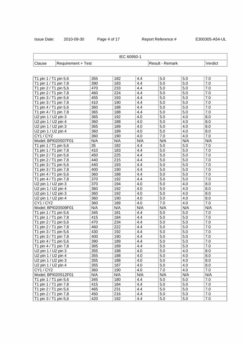
Issue Date: 2010-09-30 Page 4 of 17 Report Reference # E300305-A54-UL
IEC 60950-1
Clause Requirement + Test Result - Remark Verdict
T1 pin 1 / T1 pin 5,6 355 182 4.4 5.0 5.0 7.0 T1 pin 1 / T1 pin 7,8 390 183 4.4 5.0 5.0 7.0 T1 pin 2 / T1 pin 5,6 470 233 4.4 5.0 5.0 7.0 T1 pin 2 / T1 pin 7,8 460 224 4.4 5.0 5.0 7.0 T1 pin 3 / T1 pin 5,6 455 193 4.4 5.0 5.0 7.0 T1 pin 3 / T1 pin 7,8 410 190 4.4 5.0 5.0 7.0 T1 pin 4 / T1 pin 5,6 360 188 4.4 5.0 5.0 7.0 T1 pin 4 / T1 pin 7,8 365 188 4.4 5.0 5.0 7.0 U2 pin 1 / U2 pin 3 365 192 4.0 5.0 4.0 8.0 U2 pin 1 / U2 pin 4 360 188 4.0 5.0 4.0 8.0 U2 pin 1 / U2 pin 3 365 189 4.0 5.0 4.0 8.0 U2 pin 1 / U2 pin 4 360 189 4.0 5.0 4.0 8.0 CY1 / CY2 360 190 4.0 7.0 4.0 7.0 Model; BPI020S07F01 N/A N/A N/A N/A N/A N/A T1 pin 1 / T1 pin 5,6 35 182 4.4 5.0 5.0 7.0 T1 pin 1 / T1 pin 7,8 410 183 4.4 5.0 5.0 7.0 T1 pin 2 / T1 pin 5,6 450 225 4.4 5.0 5.0 7.0 T1 pin 2 / T1 pin 7,8 440 215 4.4 5.0 5.0 7.0 T1 pin 3 / T1 pin 5,6 440 193 4.4 5.0 5.0 7.0 T1 pin 3 / T1 pin 7,8 400 190 4.4 5.0 5.0 7.0 T1 pin 4 / T1 pin 5,6 360 188 4.4 5.0 5.0 7.0 T1 pin 4 / T1 pin 7,8 370 192 4.4 5.0 5.0 7.0 U2 pin 1 / U2 pin 3 370 194 4.0 5.0 4.0 8.0 U2 pin 1 / U2 pin 4 360 192 4.0 5.0 4.0 8.0 U2 pin 1 / U2 pin 3 360 192 4.0 5.0 4.0 8.0 U2 pin 1 / U2 pin 4 360 190 4.0 5.0 4.0 8.0 CY1 / CY2 360 189 4.0 7.0 4.0 7.0 Model; BPI020S09F01 N/A N/A N/A N/A N/A N/A T1 pin 1 / T1 pin 5,6 345 181 4.4 5.0 5.0 7.0 T1 pin 1 / T1 pin 7,8 415 184 4.4 5.0 5.0 7.0 T1 pin 2 / T1 pin 5,6 470 234 4.4 5.0 5.0 7.0 T1 pin 2 / T1 pin 7,8 460 222 4.4 5.0 5.0 7.0 T1 pin 3 / T1 pin 5,6 430 192 4.4 5.0 5.0 7.0 T1 pin 3 / T1 pin 7,8 400 190 4.4 5.0 5.0 7.0 T1 pin 4 / T1 pin 5,6 390 189 4.4 5.0 5.0 7.0 T1 pin 4 / T1 pin 7,8 365 189 4.4 5.0 5.0 7.0 U2 pin 1 / U2 pin 3 355 188 4.0 5.0 4.0 8.0 U2 pin 1 / U2 pin 4 355 188 4.0 5.0 4.0 8.0 U2 pin 1 / U2 pin 3 355 188 4.0 5.0 4.0 8.0 U2 pin 1 / U2 pin 4 355 187 4.0 5.0 4.0 8.0 CY1 / CY2 360 190 4.0 7.0 4.0 7.0 Model; BPI020S12F01 N/A N/A N/A N/A N/A N/A T1 pin 1 / T1 pin 5,6 345 180 4.4 5.0 5.0 7.0 T1 pin 1 / T1 pin 7,8 415 184 4.4 5.0 5.0 7.0 T1 pin 2 / T1 pin 5,6 465 231 4.4 5.0 5.0 7.0 T1 pin 2 / T1 pin 7,8 450 216 4.4 5.0 5.0 7.0 T1 pin 3 / T1 pin 5,6 420 192 4.4 5.0 5.0 7.0
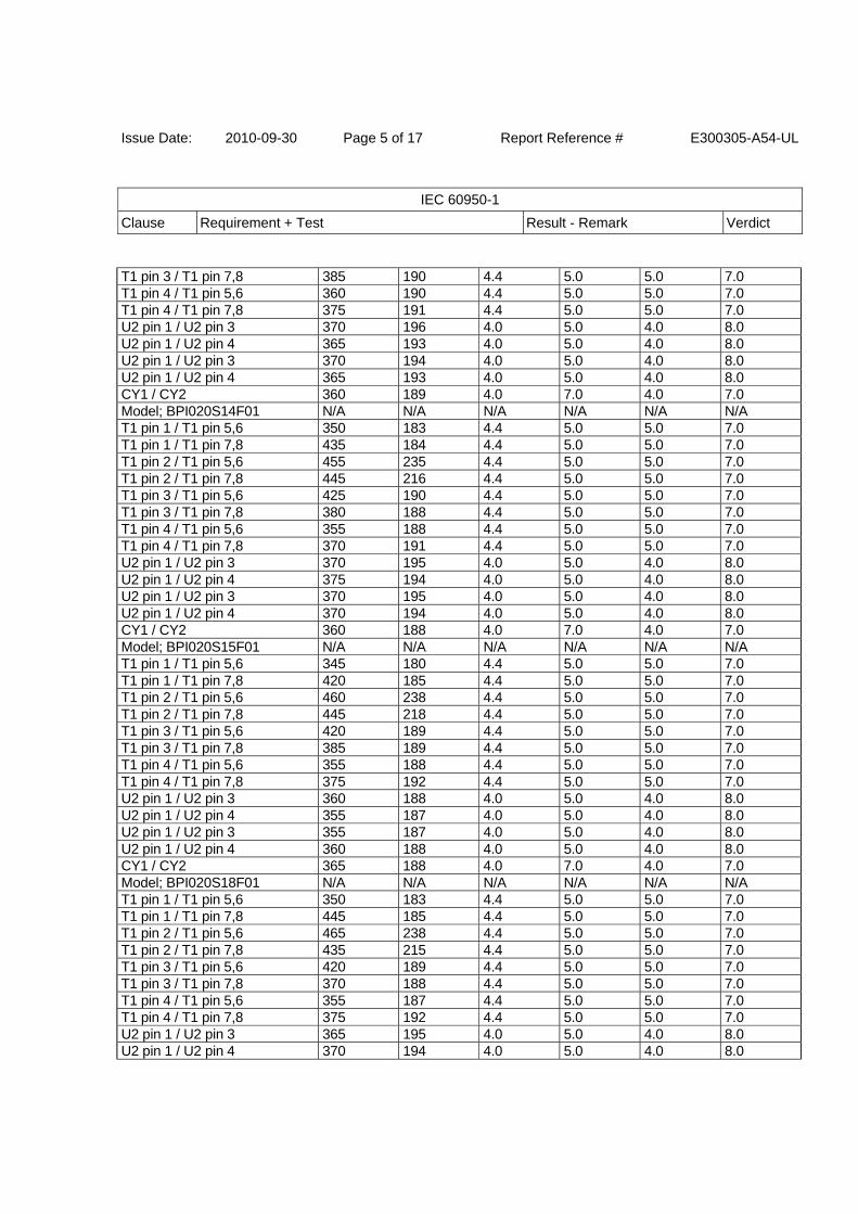
Issue Date: 2010-09-30 Page 5 of 17 Report Reference # E300305-A54-UL
IEC 60950-1
Clause Requirement + Test Result - Remark Verdict
T1 pin 3 / T1 pin 7,8 385 190 4.4 5.0 5.0 7.0 T1 pin 4 / T1 pin 5,6 360 190 4.4 5.0 5.0 7.0 T1 pin 4 / T1 pin 7,8 375 191 4.4 5.0 5.0 7.0 U2 pin 1 / U2 pin 3 370 196 4.0 5.0 4.0 8.0 U2 pin 1 / U2 pin 4 365 193 4.0 5.0 4.0 8.0 U2 pin 1 / U2 pin 3 370 194 4.0 5.0 4.0 8.0 U2 pin 1 / U2 pin 4 365 193 4.0 5.0 4.0 8.0 CY1 / CY2 360 189 4.0 7.0 4.0 7.0 Model; BPI020S14F01 N/A N/A N/A N/A N/A N/A T1 pin 1 / T1 pin 5,6 350 183 4.4 5.0 5.0 7.0 T1 pin 1 / T1 pin 7,8 435 184 4.4 5.0 5.0 7.0 T1 pin 2 / T1 pin 5,6 455 235 4.4 5.0 5.0 7.0 T1 pin 2 / T1 pin 7,8 445 216 4.4 5.0 5.0 7.0 T1 pin 3 / T1 pin 5,6 425 190 4.4 5.0 5.0 7.0 T1 pin 3 / T1 pin 7,8 380 188 4.4 5.0 5.0 7.0 T1 pin 4 / T1 pin 5,6 355 188 4.4 5.0 5.0 7.0 T1 pin 4 / T1 pin 7,8 370 191 4.4 5.0 5.0 7.0 U2 pin 1 / U2 pin 3 370 195 4.0 5.0 4.0 8.0 U2 pin 1 / U2 pin 4 375 194 4.0 5.0 4.0 8.0 U2 pin 1 / U2 pin 3 370 195 4.0 5.0 4.0 8.0 U2 pin 1 / U2 pin 4 370 194 4.0 5.0 4.0 8.0 CY1 / CY2 360 188 4.0 7.0 4.0 7.0 Model; BPI020S15F01 N/A N/A N/A N/A N/A N/A T1 pin 1 / T1 pin 5,6 345 180 4.4 5.0 5.0 7.0 T1 pin 1 / T1 pin 7,8 420 185 4.4 5.0 5.0 7.0 T1 pin 2 / T1 pin 5,6 460 238 4.4 5.0 5.0 7.0 T1 pin 2 / T1 pin 7,8 445 218 4.4 5.0 5.0 7.0 T1 pin 3 / T1 pin 5,6 420 189 4.4 5.0 5.0 7.0 T1 pin 3 / T1 pin 7,8 385 189 4.4 5.0 5.0 7.0 T1 pin 4 / T1 pin 5,6 355 188 4.4 5.0 5.0 7.0 T1 pin 4 / T1 pin 7,8 375 192 4.4 5.0 5.0 7.0 U2 pin 1 / U2 pin 3 360 188 4.0 5.0 4.0 8.0 U2 pin 1 / U2 pin 4 355 187 4.0 5.0 4.0 8.0 U2 pin 1 / U2 pin 3 355 187 4.0 5.0 4.0 8.0 U2 pin 1 / U2 pin 4 360 188 4.0 5.0 4.0 8.0 CY1 / CY2 365 188 4.0 7.0 4.0 7.0 Model; BPI020S18F01 N/A N/A N/A N/A N/A N/A T1 pin 1 / T1 pin 5,6 350 183 4.4 5.0 5.0 7.0 T1 pin 1 / T1 pin 7,8 445 185 4.4 5.0 5.0 7.0 T1 pin 2 / T1 pin 5,6 465 238 4.4 5.0 5.0 7.0 T1 pin 2 / T1 pin 7,8 435 215 4.4 5.0 5.0 7.0 T1 pin 3 / T1 pin 5,6 420 189 4.4 5.0 5.0 7.0 T1 pin 3 / T1 pin 7,8 370 188 4.4 5.0 5.0 7.0 T1 pin 4 / T1 pin 5,6 355 187 4.4 5.0 5.0 7.0 T1 pin 4 / T1 pin 7,8 375 192 4.4 5.0 5.0 7.0 U2 pin 1 / U2 pin 3 365 195 4.0 5.0 4.0 8.0 U2 pin 1 / U2 pin 4 370 194 4.0 5.0 4.0 8.0
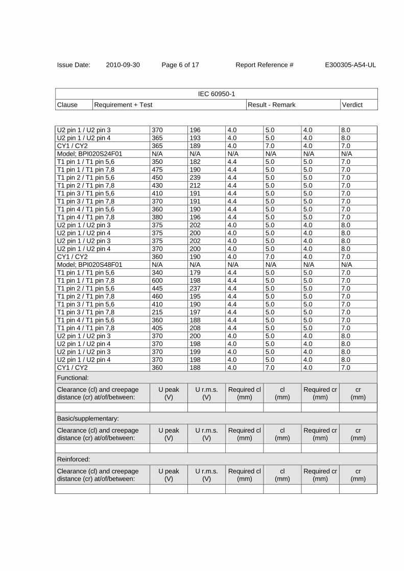
Issue Date: 2010-09-30 Page 6 of 17 Report Reference # E300305-A54-UL
IEC 60950-1
Clause Requirement + Test Result - Remark Verdict
U2 pin 1 / U2 pin 3 370 196 4.0 5.0 4.0 8.0 U2 pin 1 / U2 pin 4 365 193 4.0 5.0 4.0 8.0 CY1 / CY2 365 189 4.0 7.0 4.0 7.0 Model; BPI020S24F01 N/A N/A N/A N/A N/A N/A T1 pin 1 / T1 pin 5,6 350 182 4.4 5.0 5.0 7.0 T1 pin 1 / T1 pin 7,8 475 190 4.4 5.0 5.0 7.0 T1 pin 2 / T1 pin 5,6 450 239 4.4 5.0 5.0 7.0 T1 pin 2 / T1 pin 7,8 430 212 4.4 5.0 5.0 7.0 T1 pin 3 / T1 pin 5,6 410 191 4.4 5.0 5.0 7.0 T1 pin 3 / T1 pin 7,8 370 191 4.4 5.0 5.0 7.0 T1 pin 4 / T1 pin 5,6 360 190 4.4 5.0 5.0 7.0 T1 pin 4 / T1 pin 7,8 380 196 4.4 5.0 5.0 7.0 U2 pin 1 / U2 pin 3 375 202 4.0 5.0 4.0 8.0 U2 pin 1 / U2 pin 4 375 200 4.0 5.0 4.0 8.0 U2 pin 1 / U2 pin 3 375 202 4.0 5.0 4.0 8.0 U2 pin 1 / U2 pin 4 370 200 4.0 5.0 4.0 8.0 CY1 / CY2 360 190 4.0 7.0 4.0 7.0 Model; BPI020S48F01 N/A N/A N/A N/A N/A N/A T1 pin 1 / T1 pin 5,6 340 179 4.4 5.0 5.0 7.0 T1 pin 1 / T1 pin 7,8 600 198 4.4 5.0 5.0 7.0 T1 pin 2 / T1 pin 5,6 445 237 4.4 5.0 5.0 7.0 T1 pin 2 / T1 pin 7,8 460 195 4.4 5.0 5.0 7.0 T1 pin 3 / T1 pin 5,6 410 190 4.4 5.0 5.0 7.0 T1 pin 3 / T1 pin 7,8 215 197 4.4 5.0 5.0 7.0 T1 pin 4 / T1 pin 5,6 360 188 4.4 5.0 5.0 7.0 T1 pin 4 / T1 pin 7,8 405 208 4.4 5.0 5.0 7.0 U2 pin 1 / U2 pin 3 370 200 4.0 5.0 4.0 8.0 U2 pin 1 / U2 pin 4 370 198 4.0 5.0 4.0 8.0 U2 pin 1 / U2 pin 3 370 199 4.0 5.0 4.0 8.0 U2 pin 1 / U2 pin 4 370 198 4.0 5.0 4.0 8.0 CY1 / CY2 360 188 4.0 7.0 4.0 7.0
Functional:
Clearance (cl) and creepage distance (cr) at/of/between:
U peak (V)
U r.m.s. (V)
Required cl(mm)
cl (mm)
Required cr(mm)
cr (mm)
Basic/supplementary:
Clearance (cl) and creepage distance (cr) at/of/between:
U peak (V)
U r.m.s. (V)
Required cl(mm)
cl (mm)
Required cr(mm)
cr (mm)
Reinforced:
Clearance (cl) and creepage distance (cr) at/of/between:
U peak (V)
U r.m.s. (V)
Required cl(mm)
cl (mm)
Required cr(mm)
cr (mm)
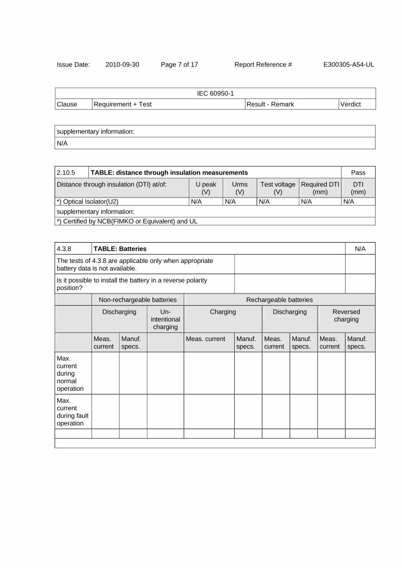
Issue Date: 2010-09-30 Page 7 of 17 Report Reference # E300305-A54-UL
IEC 60950-1
Clause Requirement + Test Result - Remark Verdict
supplementary information:
N/A
2.10.5 TABLE: distance through insulation measurements Pass
Distance through insulation (DTI) at/of: U peak (V)
Urms (V)
Test voltage (V)
Required DTI(mm)
DTI (mm)
*) Optical Isolator(U2) N/A N/A N/A N/A N/A
supplementary information:
*) Certified by NCB(FIMKO or Equivalent) and UL
4.3.8 TABLE: Batteries N/A
The tests of 4.3.8 are applicable only when appropriate battery data is not available.
Is it possible to install the battery in a reverse polarity position?
Non-rechargeable batteries Rechargeable batteries
Discharging Un- intentional charging
Charging Discharging Reversed charging
Meas. current
Manuf. specs.
Meas. current Manuf. specs.
Meas. current
Manuf. specs.
Meas. current
Manuf. specs.
Max. current during normal operation
Max. current during fault operation
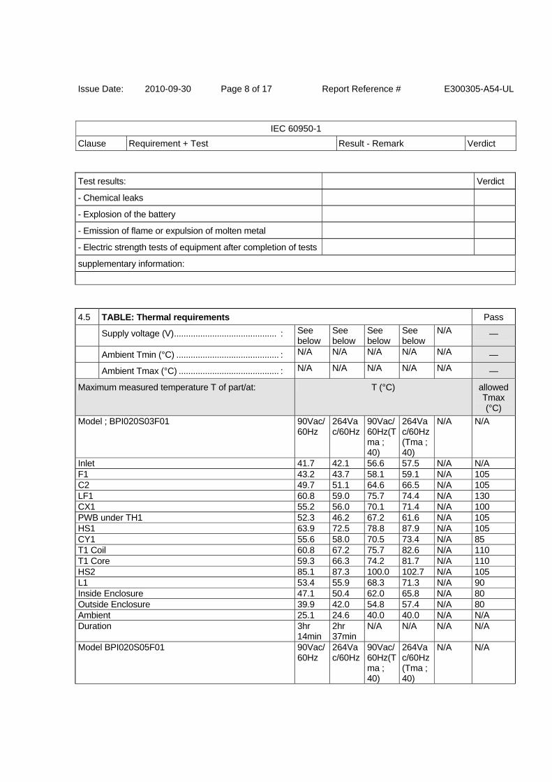
Issue Date: 2010-09-30 Page 8 of 17 Report Reference # E300305-A54-UL
IEC 60950-1
Clause Requirement + Test Result - Remark Verdict
Test results: Verdict
- Chemical leaks
- Explosion of the battery
- Emission of flame or expulsion of molten metal
- Electric strength tests of equipment after completion of tests
supplementary information:
4.5 TABLE: Thermal requirements Pass
Supply voltage (V) ........................................... : See below
See below
See below
See below
N/A —
Ambient Tmin (°C) ........................................... : N/A N/A N/A N/A N/A —
Ambient Tmax (°C) .......................................... : N/A N/A N/A N/A N/A —
Maximum measured temperature T of part/at: T (°C) allowedTmax (°C)
Model ; BPI020S03F01 90Vac/60Hz
264Vac/60Hz
90Vac/60Hz(Tma ; 40)
264Vac/60Hz(Tma ;40)
N/A N/A
Inlet 41.7 42.1 56.6 57.5 N/A N/A F1 43.2 43.7 58.1 59.1 N/A 105 C2 49.7 51.1 64.6 66.5 N/A 105 LF1 60.8 59.0 75.7 74.4 N/A 130 CX1 55.2 56.0 70.1 71.4 N/A 100 PWB under TH1 52.3 46.2 67.2 61.6 N/A 105 HS1 63.9 72.5 78.8 87.9 N/A 105 CY1 55.6 58.0 70.5 73.4 N/A 85 T1 Coil 60.8 67.2 75.7 82.6 N/A 110 T1 Core 59.3 66.3 74.2 81.7 N/A 110 HS2 85.1 87.3 100.0 102.7 N/A 105 L1 53.4 55.9 68.3 71.3 N/A 90 Inside Enclosure 47.1 50.4 62.0 65.8 N/A 80 Outside Enclosure 39.9 42.0 54.8 57.4 N/A 80 Ambient 25.1 24.6 40.0 40.0 N/A N/A Duration 3hr
14min2hr 37min
N/A N/A N/A N/A
Model BPI020S05F01 90Vac/60Hz
264Vac/60Hz
90Vac/60Hz(Tma ; 40)
264Vac/60Hz(Tma ;40)
N/A N/A
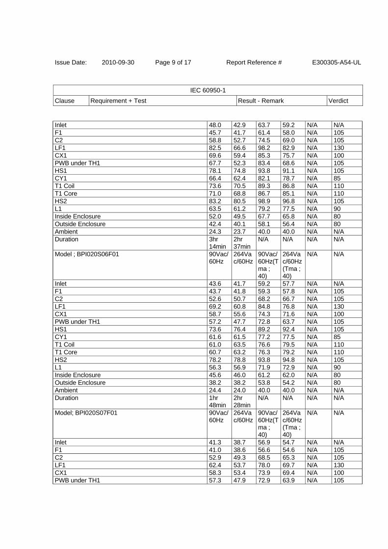
Issue Date: 2010-09-30 Page 9 of 17 Report Reference # E300305-A54-UL
IEC 60950-1
Clause Requirement + Test Result - Remark Verdict
Inlet 48.0 42.9 63.7 59.2 N/A N/A F1 45.7 41.7 61.4 58.0 N/A 105 C2 58.8 52.7 74.5 69.0 N/A 105 LF1 82.5 66.6 98.2 82.9 N/A 130 CX1 69.6 59.4 85.3 75.7 N/A 100 PWB under TH1 67.7 52.3 83.4 68.6 N/A 105 HS1 78.1 74.8 93.8 91.1 N/A 105 CY1 66.4 62.4 82.1 78.7 N/A 85 T1 Coil 73.6 70.5 89.3 86.8 N/A 110 T1 Core 71.0 68.8 86.7 85.1 N/A 110 HS2 83.2 80.5 98.9 96.8 N/A 105 L1 63.5 61.2 79.2 77.5 N/A 90 Inside Enclosure 52.0 49.5 67.7 65.8 N/A 80 Outside Enclosure 42.4 40.1 58.1 56.4 N/A 80 Ambient 24.3 23.7 40.0 40.0 N/A N/A Duration 3hr
14min2hr 37min
N/A N/A N/A N/A
Model ; BPI020S06F01 90Vac/60Hz
264Vac/60Hz
90Vac/60Hz(Tma ; 40)
264Vac/60Hz(Tma ;40)
N/A N/A
Inlet 43.6 41.7 59.2 57.7 N/A N/A F1 43.7 41.8 59.3 57.8 N/A 105 C2 52.6 50.7 68.2 66.7 N/A 105 LF1 69.2 60.8 84.8 76.8 N/A 130 CX1 58.7 55.6 74.3 71.6 N/A 100 PWB under TH1 57.2 47.7 72.8 63.7 N/A 105 HS1 73.6 76.4 89.2 92.4 N/A 105 CY1 61.6 61.5 77.2 77.5 N/A 85 T1 Coil 61.0 63.5 76.6 79.5 N/A 110 T1 Core 60.7 63.2 76.3 79.2 N/A 110 HS2 78.2 78.8 93.8 94.8 N/A 105 L1 56.3 56.9 71.9 72.9 N/A 90 Inside Enclosure 45.6 46.0 61.2 62.0 N/A 80 Outside Enclosure 38.2 38.2 53.8 54.2 N/A 80 Ambient 24.4 24.0 40.0 40.0 N/A N/A Duration 1hr
48min2hr 28min
N/A N/A N/A N/A
Model; BPI020S07F01 90Vac/60Hz
264Vac/60Hz
90Vac/60Hz(Tma ; 40)
264Vac/60Hz(Tma ;40)
N/A N/A
Inlet 41.3 38.7 56.9 54.7 N/A N/A F1 41.0 38.6 56.6 54.6 N/A 105 C2 52.9 49.3 68.5 65.3 N/A 105 LF1 62.4 53.7 78.0 69.7 N/A 130 CX1 58.3 53.4 73.9 69.4 N/A 100 PWB under TH1 57.3 47.9 72.9 63.9 N/A 105

Issue Date: 2010-09-30 Page 10 of 17 Report Reference # E300305-A54-UL
IEC 60950-1
Clause Requirement + Test Result - Remark Verdict
HS1 68.6 69.3 84.2 85.3 N/A 105 CY1 60.3 58.5 75.9 74.5 N/A 85 T1 Coil 65.1 65.5 80.7 81.5 N/A 110 T1 Core 63.3 64.5 78.9 80.5 N/A 110 HS2 75.3 75.5 90.9 91.5 N/A 105 L1 48.8 48.3 64.4 64.3 N/A 90 Inside Enclosure 48.5 48.5 64.1 64.5 N/A 80 Outside Enclosure 40.1 40.5 55.7 56.5 N/A 80 Ambient 24.4 24.0 40.0 40.0 N/A N/A Duration 1hr
48min2hrs 28min
N/A N/A N/A N/A
Model; BPI020S09F01 90Vac/60Hz
264Vac/60Hz
90Vac/60Hz(Tma ; 40)
264Vac/60Hz(Tma ;40)
N/A N/A
Inlet 48.0 42.9 62.8 58.3 N/A N/A F1 47.4 42.7 62.2 58.1 N/A 105 C2 57.8 51.7 72.6 67.1 N/A 105 LF1 72.1 60.0 86.9 75.4 N/A 130 CX1 60.7 53.6 75.5 69.0 N/A 100 PWB under TH1 63.4 50.6 78.2 66.0 N/A 105 HS1 78.8 75.6 93.6 91.0 N/A 105 CY1 61.3 58.0 76.1 73.4 N/A 85 T1 Coil 69.3 67.4 84.1 82.8 N/A 110 T1 Core 65.7 64.6 80.5 80.0 N/A 110 HS2 81.4 80.9 96.2 96.3 N/A 105 L1 56.0 55.0 70.8 70.4 N/A 90 Inside Enclosure 52.5 50.9 67.3 66.3 N/A 80 Outside Enclosure 42.1 40.4 56.9 55.8 N/A 80 Ambient 25.2 24.6 40.0 40.0 N/A N/A Duration 2hrs
40min2hrs 34min
N/A N/A N/A N/A
Model ; BPI020S12F01 90Vac/60Hz
264Vac/60Hz
90Vac/60Hz(Tma ; 40)
264Vac/60Hz(Tma ;40)
N/A N/A
Inlet 41.6 37.7 56.1 52.9 N/A N/A F1 45.0 40.8 59.5 56.0 N/A 105 C2 55.5 49.8 70.0 65.0 N/A 105 LF1 72.1 58.4 86.6 73.6 N/A 130 CX1 59.8 52.5 74.3 67.7 N/A 100 PWB under TH1 59.9 47.1 74.4 62.3 N/A 105 HS1 68.2 64.9 82.7 80.1 N/A 105 CY1 55.2 52.4 69.7 67.6 N/A 85 T1 Coil 61.6 61.0 76.1 76.2 N/A 110 T1 Core 65.0 65.7 79.5 80.9 N/A 110 HS2 70.2 70.1 84.7 85.3 N/A 105 L1 48.8 48.7 63.3 63.9 N/A 90
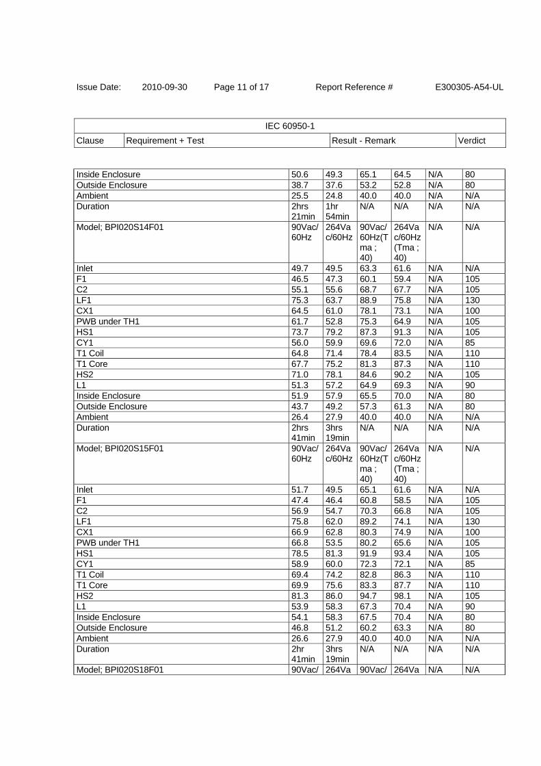
Issue Date: 2010-09-30 Page 11 of 17 Report Reference # E300305-A54-UL
IEC 60950-1
Clause Requirement + Test Result - Remark Verdict
Inside Enclosure 50.6 49.3 65.1 64.5 N/A 80 Outside Enclosure 38.7 37.6 53.2 52.8 N/A 80 Ambient 25.5 24.8 40.0 40.0 N/A N/A Duration 2hrs
21min1hr 54min
N/A N/A N/A N/A
Model; BPI020S14F01 90Vac/60Hz
264Vac/60Hz
90Vac/60Hz(Tma ; 40)
264Vac/60Hz(Tma ;40)
N/A N/A
Inlet 49.7 49.5 63.3 61.6 N/A N/A F1 46.5 47.3 60.1 59.4 N/A 105 C2 55.1 55.6 68.7 67.7 N/A 105 LF1 75.3 63.7 88.9 75.8 N/A 130 CX1 64.5 61.0 78.1 73.1 N/A 100 PWB under TH1 61.7 52.8 75.3 64.9 N/A 105 HS1 73.7 79.2 87.3 91.3 N/A 105 CY1 56.0 59.9 69.6 72.0 N/A 85 T1 Coil 64.8 71.4 78.4 83.5 N/A 110 T1 Core 67.7 75.2 81.3 87.3 N/A 110 HS2 71.0 78.1 84.6 90.2 N/A 105 L1 51.3 57.2 64.9 69.3 N/A 90 Inside Enclosure 51.9 57.9 65.5 70.0 N/A 80 Outside Enclosure 43.7 49.2 57.3 61.3 N/A 80 Ambient 26.4 27.9 40.0 40.0 N/A N/A Duration 2hrs
41min3hrs 19min
N/A N/A N/A N/A
Model; BPI020S15F01 90Vac/60Hz
264Vac/60Hz
90Vac/60Hz(Tma ; 40)
264Vac/60Hz(Tma ;40)
N/A N/A
Inlet 51.7 49.5 65.1 61.6 N/A N/A F1 47.4 46.4 60.8 58.5 N/A 105 C2 56.9 54.7 70.3 66.8 N/A 105 LF1 75.8 62.0 89.2 74.1 N/A 130 CX1 66.9 62.8 80.3 74.9 N/A 100 PWB under TH1 66.8 53.5 80.2 65.6 N/A 105 HS1 78.5 81.3 91.9 93.4 N/A 105 CY1 58.9 60.0 72.3 72.1 N/A 85 T1 Coil 69.4 74.2 82.8 86.3 N/A 110 T1 Core 69.9 75.6 83.3 87.7 N/A 110 HS2 81.3 86.0 94.7 98.1 N/A 105 L1 53.9 58.3 67.3 70.4 N/A 90 Inside Enclosure 54.1 58.3 67.5 70.4 N/A 80 Outside Enclosure 46.8 51.2 60.2 63.3 N/A 80 Ambient 26.6 27.9 40.0 40.0 N/A N/A Duration 2hr
41min3hrs 19min
N/A N/A N/A N/A
Model; BPI020S18F01 90Vac/ 264Va 90Vac/ 264Va N/A N/A
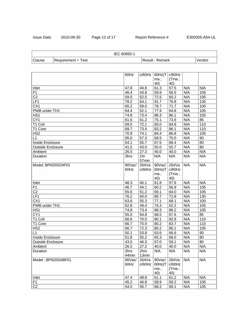
Issue Date: 2010-09-30 Page 12 of 17 Report Reference # E300305-A54-UL
IEC 60950-1
Clause Requirement + Test Result - Remark Verdict
60Hz c/60Hz 60Hz(Tma ; 40)
c/60Hz(Tma ;40)
Inlet 47.8 44.8 61.3 57.5 N/A N/A F1 46.4 43.8 59.9 56.5 N/A 105 C2 59.0 52.5 72.5 65.2 N/A 105 LF1 78.2 64.1 91.7 76.8 N/A 130 CX1 65.2 59.0 78.7 71.7 N/A 100 PWB under TH1 64.4 52.1 77.9 64.8 N/A 105 HS1 74.8 73.4 88.3 86.1 N/A 105 CY1 61.6 61.2 75.1 73.9 N/A 85 T1 Coil 69.5 72.1 83.0 84.8 N/A 110 T1 Core 69.7 73.4 83.2 86.1 N/A 110 HS2 70.9 74.1 84.4 86.8 N/A 105 L1 55.0 57.3 68.5 70.0 N/A 90 Inside Enclosure 54.1 55.7 67.6 68.4 N/A 80 Outside Enclosure 41.5 43.0 55.0 55.7 N/A 80 Ambient 26.5 27.3 40.0 40.0 N/A N/A Duration 3hrs 1hr
57minN/A N/A N/A N/A
Model; BPI020S24F01 90Vac/60Hz
264Vac/60Hz
90Vac/60Hz(Tma ; 40)
264Vac/60Hz(Tma ;40)
N/A N/A
Inlet 48.3 45.1 61.8 57.9 N/A N/A F1 46.7 44.1 60.2 56.9 N/A 105 C2 55.6 51.2 69.1 64.0 N/A 105 LF1 76.2 60.0 89.7 72.8 N/A 130 CX1 63.6 55.3 77.1 68.1 N/A 100 PWB under TH1 62.8 49.4 76.3 62.2 N/A 105 HS1 74.8 73.4 88.3 86.2 N/A 105 CY1 55.0 54.8 68.5 67.6 N/A 85 T1 Coil 66.6 70.0 80.1 82.8 N/A 110 T1 Core 66.7 70.9 80.2 83.7 N/A 110 HS2 66.7 72.3 80.2 85.1 N/A 105 L1 50.1 53.8 63.6 66.6 N/A 90 Inside Enclosure 51.8 55.2 65.3 68.0 N/A 80 Outside Enclosure 43.5 46.3 57.0 59.1 N/A 80 Ambient 26.5 27.2 40.0 40.0 N/A N/A Duration 2hrs
44min2hrs 13min
N/A N/A N/A N/A
Model ; BPI020S48F01 90Vac/60Hz
264Vac/60Hz
90Vac/60Hz(Tma ; 40)
264Vac/60Hz(Tma ;40)
N/A N/A
Inlet 47.4 48.8 61.1 61.2 N/A N/A F1 45.2 46.8 58.9 59.2 N/A 105 C2 54.5 56.7 68.2 69.1 N/A 105
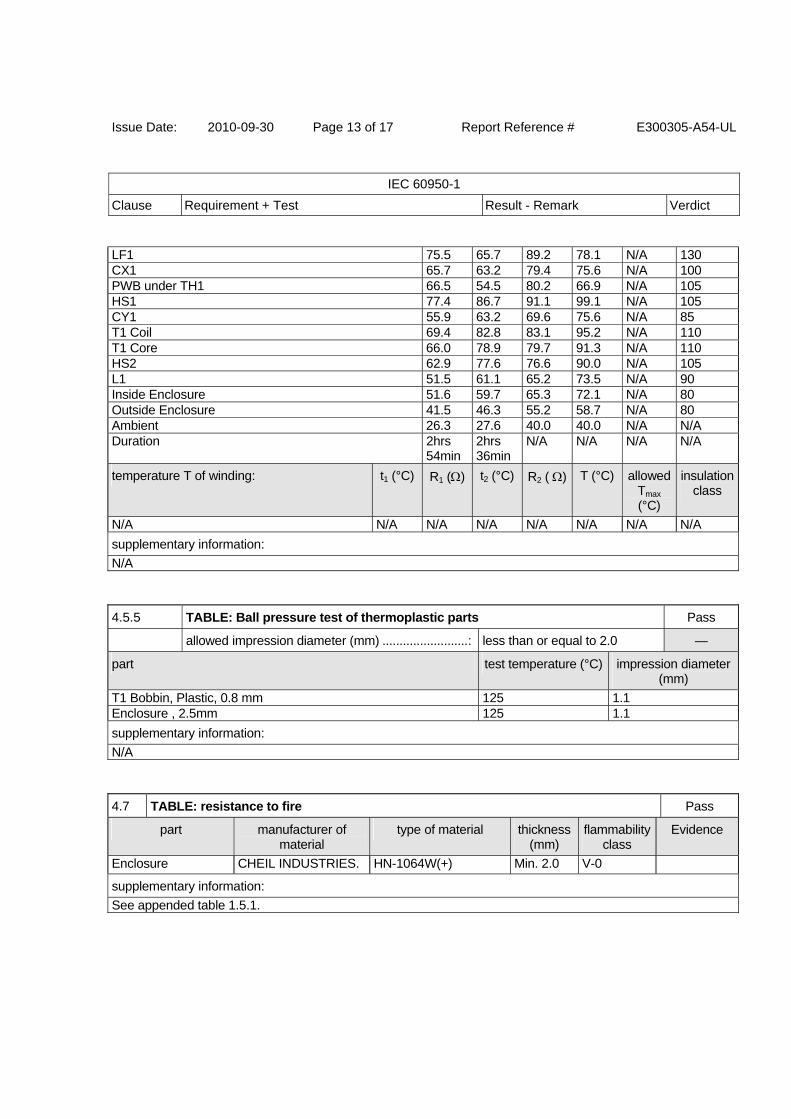
Issue Date: 2010-09-30 Page 13 of 17 Report Reference # E300305-A54-UL
IEC 60950-1
Clause Requirement + Test Result - Remark Verdict
LF1 75.5 65.7 89.2 78.1 N/A 130 CX1 65.7 63.2 79.4 75.6 N/A 100 PWB under TH1 66.5 54.5 80.2 66.9 N/A 105 HS1 77.4 86.7 91.1 99.1 N/A 105 CY1 55.9 63.2 69.6 75.6 N/A 85 T1 Coil 69.4 82.8 83.1 95.2 N/A 110 T1 Core 66.0 78.9 79.7 91.3 N/A 110 HS2 62.9 77.6 76.6 90.0 N/A 105 L1 51.5 61.1 65.2 73.5 N/A 90 Inside Enclosure 51.6 59.7 65.3 72.1 N/A 80 Outside Enclosure 41.5 46.3 55.2 58.7 N/A 80 Ambient 26.3 27.6 40.0 40.0 N/A N/A Duration 2hrs
54min2hrs 36min
N/A N/A N/A N/A
temperature T of winding: t1 (°C) R1 () t2 (°C) R2 ( ) T (°C) allowed Tmax (°C)
insulation class
N/A N/A N/A N/A N/A N/A N/A N/A
supplementary information:
N/A
4.5.5 TABLE: Ball pressure test of thermoplastic parts Pass
allowed impression diameter (mm) ......................... : less than or equal to 2.0 —
part test temperature (°C) impression diameter (mm)
T1 Bobbin, Plastic, 0.8 mm 125 1.1 Enclosure , 2.5mm 125 1.1
supplementary information:
N/A
4.7 TABLE: resistance to fire Pass
part manufacturer of material
type of material thickness (mm)
flammability class
Evidence
Enclosure CHEIL INDUSTRIES. HN-1064W(+) Min. 2.0 V-0 supplementary information:
See appended table 1.5.1.
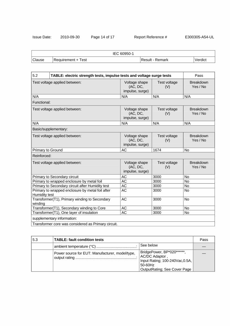
Issue Date: 2010-09-30 Page 14 of 17 Report Reference # E300305-A54-UL
IEC 60950-1
Clause Requirement + Test Result - Remark Verdict
5.2 TABLE: electric strength tests, impulse tests and voltage surge tests Pass
Test voltage applied between: Voltage shape (AC, DC,
impulse, surge)
Test voltage (V)
Breakdown Yes / No
N/A N/A N/A N/A
Functional:
Test voltage applied between: Voltage shape (AC, DC,
impulse, surge)
Test voltage (V)
Breakdown Yes / No
N/A N/A N/A N/A
Basic/supplementary:
Test voltage applied between: Voltage shape (AC, DC,
impulse, surge)
Test voltage (V)
Breakdown Yes / No
Primary to Ground AC 1674 No
Reinforced:
Test voltage applied between: Voltage shape (AC, DC,
impulse, surge)
Test voltage (V)
Breakdown Yes / No
Primary to Secondary circuit AC 3000 No Primary to wrapped enclosure by metal foil AC 3000 No Primary to Secondary circuit after Humidity test AC 3000 No Primary to wrapped enclosure by metal foil after Humidity test
AC 3000 No
Transformer(T1), Primary winding to Secondary winding
AC 3000 No
Transformer(T1), Secondary winding to Core AC 3000 No Transformer(T1), One layer of insulation AC 3000 No
supplementary information:
Transformer core was considered as Primary circuit.
5.3 TABLE: fault condition tests Pass
ambient temperature (°C) ........................................ : See below —
Power source for EUT: Manufacturer, model/type, output rating ............................................................. :
BridgePower, BP*020******, AC/DC Adaptor , Input Rating; 100-240Vac,0.5A, 50-60Hz OutputRating; See Cover Page
—
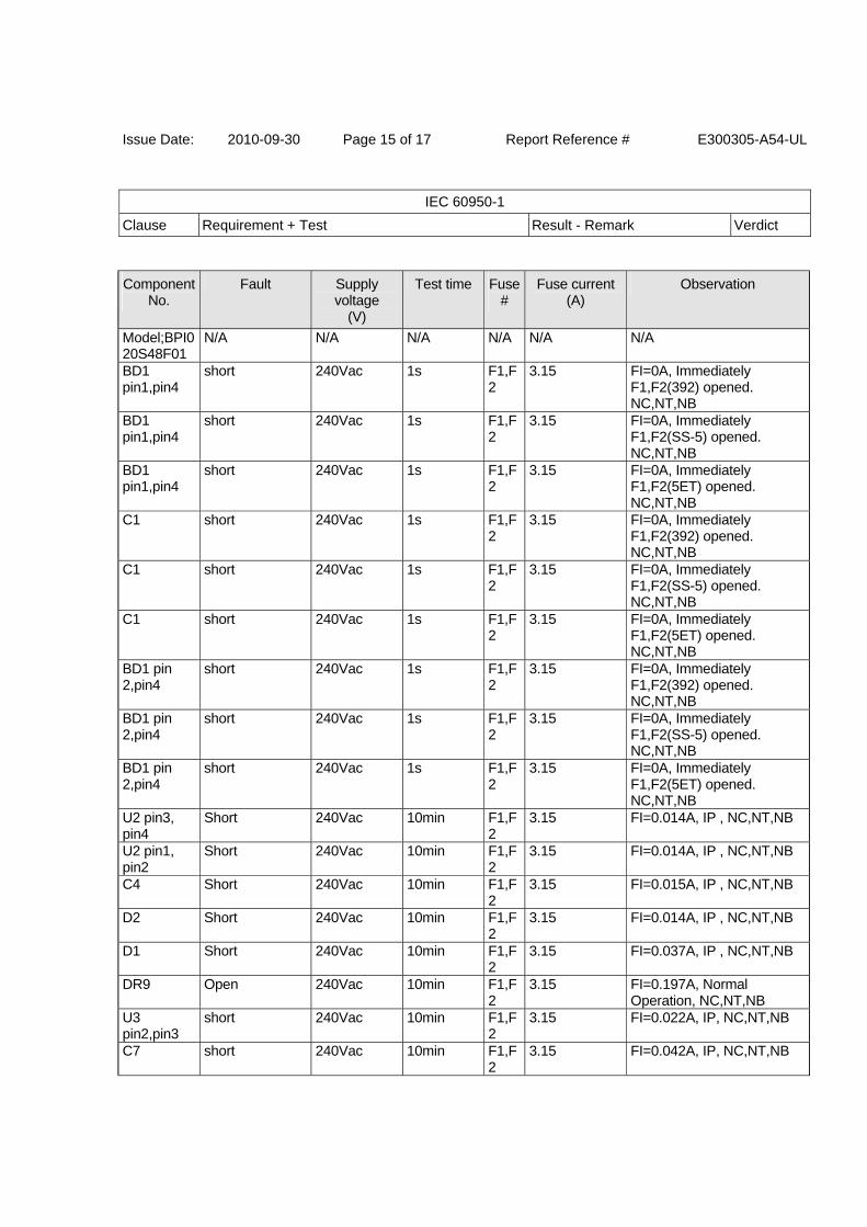
Issue Date: 2010-09-30 Page 15 of 17 Report Reference # E300305-A54-UL
IEC 60950-1
Clause Requirement + Test Result - Remark Verdict
Component No.
Fault Supply voltage
(V)
Test time Fuse #
Fuse current (A)
Observation
Model;BPI020S48F01
N/A N/A N/A N/A N/A N/A
BD1 pin1,pin4
short 240Vac 1s F1,F2
3.15 FI=0A, Immediately F1,F2(392) opened. NC,NT,NB
BD1 pin1,pin4
short 240Vac 1s F1,F2
3.15 FI=0A, Immediately F1,F2(SS-5) opened. NC,NT,NB
BD1 pin1,pin4
short 240Vac 1s F1,F2
3.15 FI=0A, Immediately F1,F2(5ET) opened. NC,NT,NB
C1 short 240Vac 1s F1,F2
3.15 FI=0A, Immediately F1,F2(392) opened. NC,NT,NB
C1 short 240Vac 1s F1,F2
3.15 FI=0A, Immediately F1,F2(SS-5) opened. NC,NT,NB
C1 short 240Vac 1s F1,F2
3.15 FI=0A, Immediately F1,F2(5ET) opened. NC,NT,NB
BD1 pin 2,pin4
short 240Vac 1s F1,F2
3.15 FI=0A, Immediately F1,F2(392) opened. NC,NT,NB
BD1 pin 2,pin4
short 240Vac 1s F1,F2
3.15 FI=0A, Immediately F1,F2(SS-5) opened. NC,NT,NB
BD1 pin 2,pin4
short 240Vac 1s F1,F2
3.15 FI=0A, Immediately F1,F2(5ET) opened. NC,NT,NB
U2 pin3, pin4
Short 240Vac 10min F1,F2
3.15 FI=0.014A, IP , NC,NT,NB
U2 pin1, pin2
Short 240Vac 10min F1,F2
3.15 FI=0.014A, IP , NC,NT,NB
C4 Short 240Vac 10min F1,F2
3.15 FI=0.015A, IP , NC,NT,NB
D2 Short 240Vac 10min F1,F2
3.15 FI=0.014A, IP , NC,NT,NB
D1 Short 240Vac 10min F1,F2
3.15 FI=0.037A, IP , NC,NT,NB
DR9 Open 240Vac 10min F1,F2
3.15 FI=0.197A, Normal Operation, NC,NT,NB
U3 pin2,pin3
short 240Vac 10min F1,F2
3.15 FI=0.022A, IP, NC,NT,NB
C7 short 240Vac 10min F1,F2
3.15 FI=0.042A, IP, NC,NT,NB
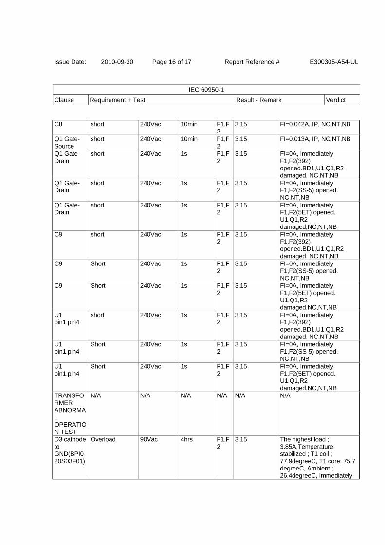
Issue Date: 2010-09-30 Page 16 of 17 Report Reference # E300305-A54-UL
IEC 60950-1
Clause Requirement + Test Result - Remark Verdict
C8 short 240Vac 10min F1,F2
3.15 FI=0.042A, IP, NC,NT,NB
Q1 Gate-Source
short 240Vac 10min F1,F2
3.15 FI=0.013A, IP, NC,NT,NB
Q1 Gate-Drain
short 240Vac 1s F1,F2
3.15 FI=0A, Immediately F1,F2(392) opened.BD1,U1,Q1,R2 damaged, NC,NT,NB
Q1 Gate-Drain
short 240Vac 1s F1,F2
3.15 FI=0A, Immediately F1,F2(SS-5) opened. NC,NT,NB
Q1 Gate-Drain
short 240Vac 1s F1,F2
3.15 FI=0A, Immediately F1,F2(5ET) opened. U1,Q1,R2 damaged,NC,NT,NB
C9 short 240Vac 1s F1,F2
3.15 FI=0A, Immediately F1,F2(392) opened.BD1,U1,Q1,R2 damaged, NC,NT,NB
C9 Short 240Vac 1s F1,F2
3.15 FI=0A, Immediately F1,F2(SS-5) opened. NC,NT,NB
C9 Short 240Vac 1s F1,F2
3.15 FI=0A, Immediately F1,F2(5ET) opened. U1,Q1,R2 damaged,NC,NT,NB
U1 pin1,pin4
short 240Vac 1s F1,F2
3.15 FI=0A, Immediately F1,F2(392) opened.BD1,U1,Q1,R2 damaged, NC,NT,NB
U1 pin1,pin4
Short 240Vac 1s F1,F2
3.15 FI=0A, Immediately F1,F2(SS-5) opened. NC,NT,NB
U1 pin1,pin4
Short 240Vac 1s F1,F2
3.15 FI=0A, Immediately F1,F2(5ET) opened. U1,Q1,R2 damaged,NC,NT,NB
TRANSFORMER ABNORMAL OPERATION TEST
N/A N/A N/A N/A N/A N/A
D3 cathode to GND(BPI020S03F01)
Overload 90Vac 4hrs F1,F2
3.15 The highest load ; 3.85A,Temperature stabilized ; T1 coil ; 77.9degreeC, T1 core; 75.7 degreeC, Ambient ; 26.4degreeC, Immediately
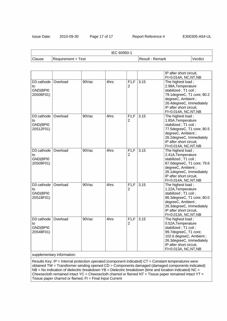
Issue Date: 2010-09-30 Page 17 of 17 Report Reference # E300305-A54-UL
IEC 60950-1
Clause Requirement + Test Result - Remark Verdict
IP after short circuit, FI=0.014A, NC,NT,NB
D3 cathode to GND(BPI020S06F01)
Overload 90Vac 4hrs F1,F2
3.15 The highest load ; 2.98A,Temperature stabilized ; T1 coil ; 79.1degreeC, T1 core; 80.2 degreeC, Ambient ; 26.4degreeC, Immediately IP after short circuit, FI=0.014A, NC,NT,NB
D3 cathode to GND(BPI020S12F01)
Overload 90Vac 4hrs F1,F2
3.15 The highest load ; 1.85A,Temperature stabilized ; T1 coil ; 77.5degreeC, T1 core; 80.5 degreeC, Ambient ; 26.2degreeC, Immediately IP after short circuit, FI=0.014A, NC,NT,NB
D3 cathode to GND(BPI020S09F01)
Overload 90Vac 4hrs F1,F2
3.15 The highest load ; 2.41A,Temperature stabilized ; T1 coil ; 87.0degreeC, T1 core; 79.6 degreeC, Ambient ; 26.1degreeC, Immediately IP after short circuit, FI=0.014A, NC,NT,NB
D3 cathode to GND(BPI020S18F01)
Overload 90Vac 4hrs F1,F2
3.15 The highest load ; 1.22A,Temperature stabilized ; T1 coil ; 86.3degreeC, T1 core; 80.0 degreeC, Ambient ; 26.3degreeC, Immediately IP after short circuit, FI=0.013A, NC,NT,NB
D3 cathode to GND(BPI020S48F01)
Overload 90Vac 4hrs F1,F2
3.15 The highest load ; 0.52A,Temperature stabilized ; T1 coil ; 99.7degreeC, T1 core; 102.6 degreeC, Ambient ; 26.3degreeC, Immediately IP after short circuit, FI=0.013A, NC,NT,NB
supplementary information:
Results Key: IP = Internal protection operated (component indicated) CT = Constant temperatures were obtained TW = Transformer winding opened CD = Components damaged (damaged components indicated) NB = No indication of dielectric breakdown YB = Dielectric breakdown (time and location indicated) NC = Cheesecloth remained intact YC = Cheesecloth charred or flamed NT = Tissue paper remained intact YT = Tissue paper charred or flamed, FI = Final Input Current
Issue Date: 2010-09-30 Page 1 of 10 Report Reference # E300305-A54-UL
Enclosure National Differences
USA / Canada
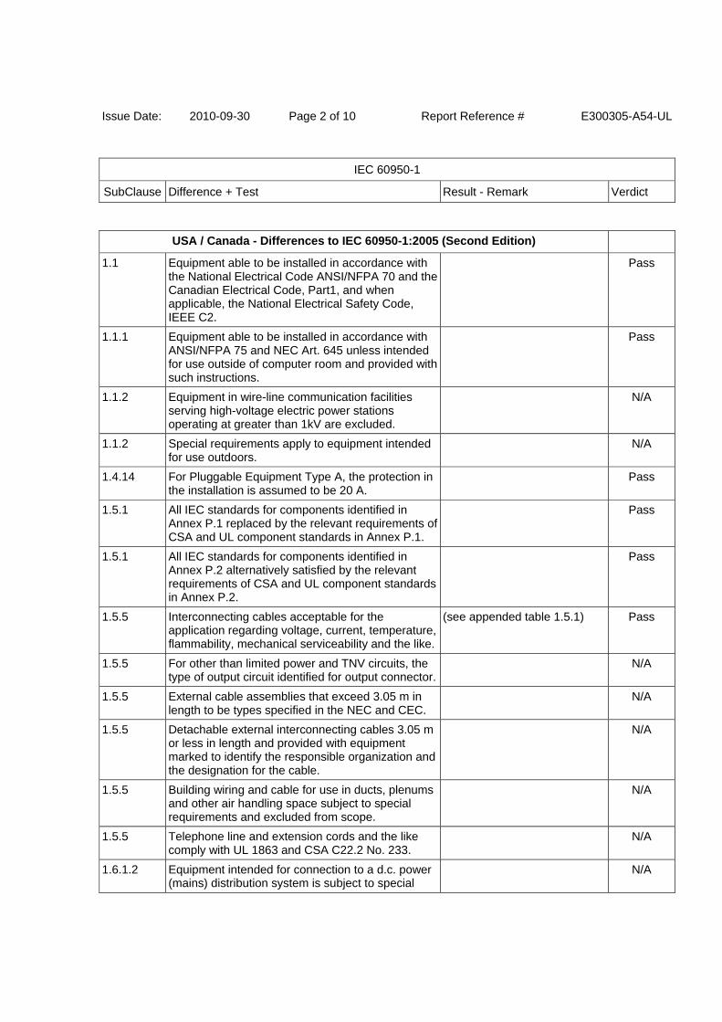
Issue Date: 2010-09-30 Page 2 of 10 Report Reference # E300305-A54-UL
IEC 60950-1
SubClause Difference + Test Result - Remark Verdict
USA / Canada - Differences to IEC 60950-1:2005 (Second Edition)
1.1 Equipment able to be installed in accordance with the National Electrical Code ANSI/NFPA 70 and the Canadian Electrical Code, Part1, and when applicable, the National Electrical Safety Code, IEEE C2.
Pass
1.1.1 Equipment able to be installed in accordance with ANSI/NFPA 75 and NEC Art. 645 unless intended for use outside of computer room and provided with such instructions.
Pass
1.1.2 Equipment in wire-line communication facilities serving high-voltage electric power stations operating at greater than 1kV are excluded.
N/A
1.1.2 Special requirements apply to equipment intended for use outdoors.
N/A
1.4.14 For Pluggable Equipment Type A, the protection in the installation is assumed to be 20 A.
Pass
1.5.1 All IEC standards for components identified in Annex P.1 replaced by the relevant requirements of CSA and UL component standards in Annex P.1.
Pass
1.5.1 All IEC standards for components identified in Annex P.2 alternatively satisfied by the relevant requirements of CSA and UL component standards in Annex P.2.
Pass
1.5.5 Interconnecting cables acceptable for the application regarding voltage, current, temperature, flammability, mechanical serviceability and the like.
(see appended table 1.5.1) Pass
1.5.5 For other than limited power and TNV circuits, the type of output circuit identified for output connector.
N/A
1.5.5 External cable assemblies that exceed 3.05 m in length to be types specified in the NEC and CEC.
N/A
1.5.5 Detachable external interconnecting cables 3.05 m or less in length and provided with equipment marked to identify the responsible organization and the designation for the cable.
N/A
1.5.5 Building wiring and cable for use in ducts, plenums and other air handling space subject to special requirements and excluded from scope.
N/A
1.5.5 Telephone line and extension cords and the like comply with UL 1863 and CSA C22.2 No. 233.
N/A
1.6.1.2 Equipment intended for connection to a d.c. power (mains) distribution system is subject to special
N/A
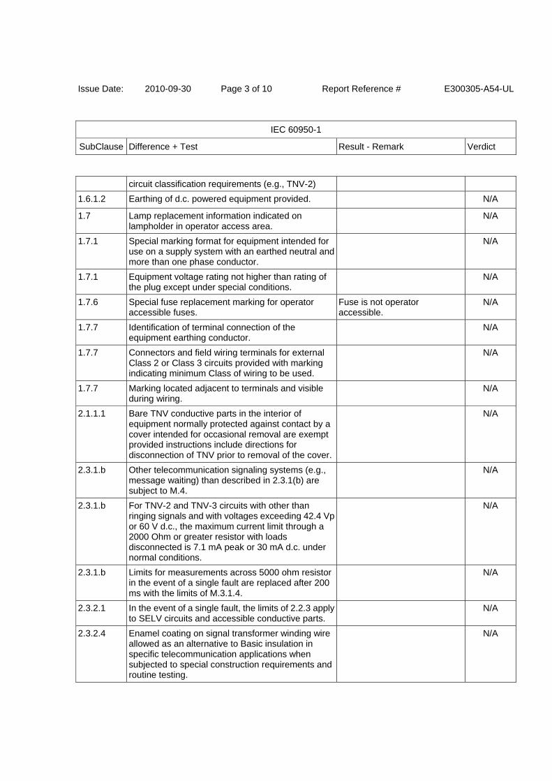
Issue Date: 2010-09-30 Page 3 of 10 Report Reference # E300305-A54-UL
IEC 60950-1
SubClause Difference + Test Result - Remark Verdict
circuit classification requirements (e.g., TNV-2)
1.6.1.2 Earthing of d.c. powered equipment provided. N/A
1.7 Lamp replacement information indicated on lampholder in operator access area.
N/A
1.7.1 Special marking format for equipment intended for use on a supply system with an earthed neutral and more than one phase conductor.
N/A
1.7.1 Equipment voltage rating not higher than rating of the plug except under special conditions.
N/A
1.7.6 Special fuse replacement marking for operator accessible fuses.
Fuse is not operator accessible.
N/A
1.7.7 Identification of terminal connection of the equipment earthing conductor.
N/A
1.7.7 Connectors and field wiring terminals for external Class 2 or Class 3 circuits provided with marking indicating minimum Class of wiring to be used.
N/A
1.7.7 Marking located adjacent to terminals and visible during wiring.
N/A
2.1.1.1 Bare TNV conductive parts in the interior of equipment normally protected against contact by a cover intended for occasional removal are exempt provided instructions include directions for disconnection of TNV prior to removal of the cover.
N/A
2.3.1.b Other telecommunication signaling systems (e.g., message waiting) than described in 2.3.1(b) are subject to M.4.
N/A
2.3.1.b For TNV-2 and TNV-3 circuits with other than ringing signals and with voltages exceeding 42.4 Vp or 60 V d.c., the maximum current limit through a 2000 Ohm or greater resistor with loads disconnected is 7.1 mA peak or 30 mA d.c. under normal conditions.
N/A
2.3.1.b Limits for measurements across 5000 ohm resistor in the event of a single fault are replaced after 200 ms with the limits of M.3.1.4.
N/A
2.3.2.1 In the event of a single fault, the limits of 2.2.3 apply to SELV circuits and accessible conductive parts.
N/A
2.3.2.4 Enamel coating on signal transformer winding wire allowed as an alternative to Basic insulation in specific telecommunication applications when subjected to special construction requirements and routine testing.
N/A
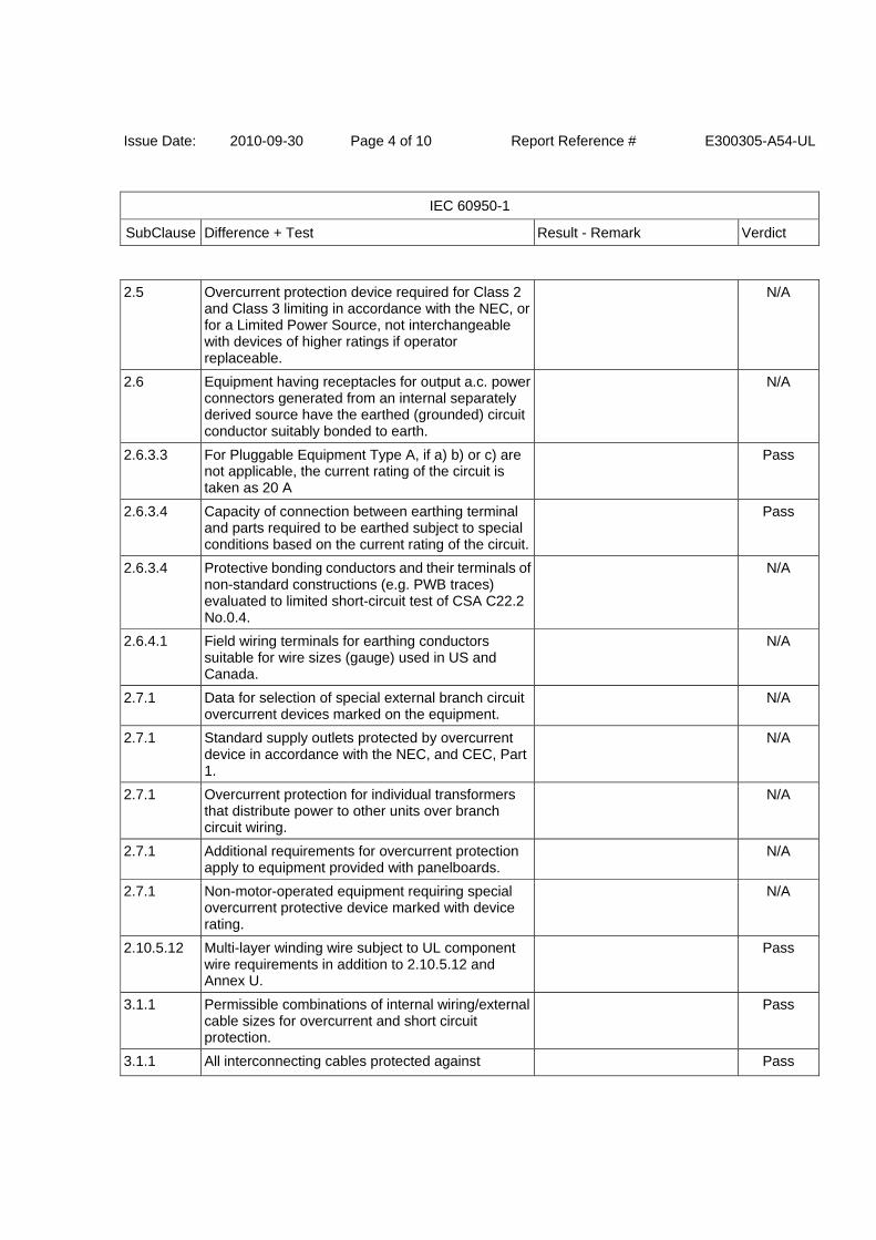
Issue Date: 2010-09-30 Page 4 of 10 Report Reference # E300305-A54-UL
IEC 60950-1
SubClause Difference + Test Result - Remark Verdict
2.5 Overcurrent protection device required for Class 2 and Class 3 limiting in accordance with the NEC, or for a Limited Power Source, not interchangeable with devices of higher ratings if operator replaceable.
N/A
2.6 Equipment having receptacles for output a.c. power connectors generated from an internal separately derived source have the earthed (grounded) circuit conductor suitably bonded to earth.
N/A
2.6.3.3 For Pluggable Equipment Type A, if a) b) or c) are not applicable, the current rating of the circuit is taken as 20 A
Pass
2.6.3.4 Capacity of connection between earthing terminal and parts required to be earthed subject to special conditions based on the current rating of the circuit.
Pass
2.6.3.4 Protective bonding conductors and their terminals of non-standard constructions (e.g. PWB traces) evaluated to limited short-circuit test of CSA C22.2 No.0.4.
N/A
2.6.4.1 Field wiring terminals for earthing conductors suitable for wire sizes (gauge) used in US and Canada.
N/A
2.7.1 Data for selection of special external branch circuit overcurrent devices marked on the equipment.
N/A
2.7.1 Standard supply outlets protected by overcurrent device in accordance with the NEC, and CEC, Part 1.
N/A
2.7.1 Overcurrent protection for individual transformers that distribute power to other units over branch circuit wiring.
N/A
2.7.1 Additional requirements for overcurrent protection apply to equipment provided with panelboards.
N/A
2.7.1 Non-motor-operated equipment requiring special overcurrent protective device marked with device rating.
N/A
2.10.5.12 Multi-layer winding wire subject to UL component wire requirements in addition to 2.10.5.12 and Annex U.
Pass
3.1.1 Permissible combinations of internal wiring/external cable sizes for overcurrent and short circuit protection.
Pass
3.1.1 All interconnecting cables protected against Pass
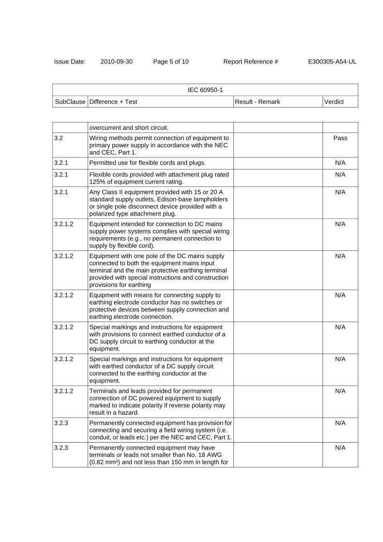
Issue Date: 2010-09-30 Page 5 of 10 Report Reference # E300305-A54-UL
IEC 60950-1
SubClause Difference + Test Result - Remark Verdict
overcurrent and short circuit.
3.2 Wiring methods permit connection of equipment to primary power supply in accordance with the NEC and CEC, Part 1.
Pass
3.2.1 Permitted use for flexible cords and plugs. N/A
3.2.1 Flexible cords provided with attachment plug rated 125% of equipment current rating.
N/A
3.2.1 Any Class II equipment provided with 15 or 20 A standard supply outlets, Edison-base lampholders or single pole disconnect device provided with a polarized type attachment plug.
N/A
3.2.1.2 Equipment intended for connection to DC mains supply power systems complies with special wiring requirements (e.g., no permanent connection to supply by flexible cord).
N/A
3.2.1.2 Equipment with one pole of the DC mains supply connected to both the equipment mains input terminal and the main protective earthing terminal provided with special instructions and construction provisions for earthing
N/A
3.2.1.2 Equipment with means for connecting supply to earthing electrode conductor has no switches or protective devices between supply connection and earthing electrode connection.
N/A
3.2.1.2 Special markings and instructions for equipment with provisions to connect earthed conductor of a DC supply circuit to earthing conductor at the equipment.
N/A
3.2.1.2 Special markings and instructions for equipment with earthed conductor of a DC supply circuit connected to the earthing conductor at the equipment.
N/A
3.2.1.2 Terminals and leads provided for permanent connection of DC powered equipment to supply marked to indicate polarity if reverse polarity may result in a hazard.
N/A
3.2.3 Permanently connected equipment has provision for connecting and securing a field wiring system (i.e. conduit, or leads etc.) per the NEC and CEC, Part 1.
N/A
3.2.3 Permanently connected equipment may have terminals or leads not smaller than No. 18 AWG (0.82 mm²) and not less than 150 mm in length for
N/A

Issue Date: 2010-09-30 Page 6 of 10 Report Reference # E300305-A54-UL
IEC 60950-1
SubClause Difference + Test Result - Remark Verdict
connection of field installed wiring.
3.2.3 If supply wires exceed 60 °C, marking indicates use of 75 °C or 90 °C wiring for supply connection as appropriate.
N/A
3.2.3 Equipment compatible with suitable trade sizes of conduits and cables.
N/A
3.2.5 Length of power supply cord limited to between 1.5 and 4.5 m unless shorter length used when intended for a special installation.
N/A
3.2.5 Conductors in power supply cords sized according to NEC and CEC, Part I.
N/A
3.2.5 Power supply cords and cord sets incorporate flexible cords suitable for the particular application.
N/A
3.2.6 Strain relief provided for non-detachable interconnecting cables not supplied by a limited power source.
N/A
3.2.9 Adequate wire bending space and volume of field wiring compartment required to properly make the field connections.
N/A
3.2.9 Equipment intended solely for installation in Restricted Access Locations using low voltage d.c. systems may not need provision for connecting and securing a field wiring system. A method of securing wiring or instructions provided to ensure the wiring is protected from abuse.
N/A
3.3 Field wiring terminals provided for interconnection of units for other then LPS or Class 2 circuits also comply with 3.3.
N/A
3.3 Interconnection of units by LPS or Class 2 conductors may have field wiring connectors other than those specified in 3.3 if wiring is reliably separated.
N/A
3.3.1 Terminals for the connection of neutral conductor identified by a distinctive white marking or other equally effective means.
N/A
3.3.3 Wire binding screw terminal permitted for connection of No. 10 AWG (5.3 mm²) or smaller conductor if provided with upturned lugs, cupped washer or equivalent retention.
N/A
3.3.4 Terminals accept wire sizes (gauge) used in the U.S. and Canada.
N/A
3.3.4 Terminals accept current-carrying conductors rated N/A
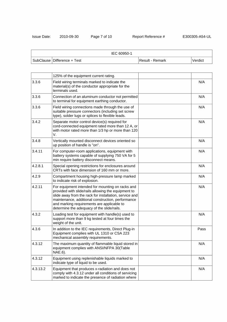
Issue Date: 2010-09-30 Page 7 of 10 Report Reference # E300305-A54-UL
IEC 60950-1
SubClause Difference + Test Result - Remark Verdict
125% of the equipment current rating.
3.3.6 Field wiring terminals marked to indicate the material(s) of the conductor appropriate for the terminals used.
N/A
3.3.6 Connection of an aluminum conductor not permitted to terminal for equipment earthing conductor.
N/A
3.3.6 Field wiring connections made through the use of suitable pressure connectors (including set screw type), solder lugs or splices to flexible leads.
N/A
3.4.2 Separate motor control device(s) required for cord-connected equipment rated more than 12 A, or with motor rated more than 1/3 hp or more than 120 V.
N/A
3.4.8 Vertically mounted disconnect devices oriented so up position of handle is "on".
N/A
3.4.11 For computer-room applications, equipment with battery systems capable of supplying 750 VA for 5 min require battery disconnect means.
N/A
4.2.8.1 Special opening restrictions for enclosures around CRTs with face dimension of 160 mm or more.
N/A
4.2.9 Compartment housing high-pressure lamp marked to indicate risk of explosion.
N/A
4.2.11 For equipment intended for mounting on racks and provided with slide/rails allowing the equipment to slide away from the rack for installation, service and maintenance, additional construction, performance and marking requirements are applicable to determine the adequacy of the slide/rails.
N/A
4.3.2 Loading test for equipment with handle(s) used to support more than 9 kg tested at four times the weight of the unit.
N/A
4.3.6 In addition to the IEC requirements, Direct Plug-in Equipment complies with UL 1310 or CSA 223 mechanical assembly requirements.
Pass
4.3.12 The maximum quantity of flammable liquid stored in equipment complies with ANSI/NFPA 30(Table NAE.6).
N/A
4.3.12 Equipment using replenishable liquids marked to indicate type of liquid to be used.
N/A
4.3.13.2 Equipment that produces x-radiation and does not comply with 4.3.12 under all conditions of servicing marked to indicate the presence of radiation where
N/A
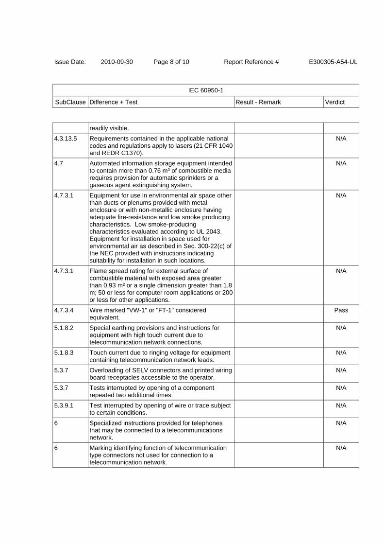
Issue Date: 2010-09-30 Page 8 of 10 Report Reference # E300305-A54-UL
IEC 60950-1
SubClause Difference + Test Result - Remark Verdict
readily visible.
4.3.13.5 Requirements contained in the applicable national codes and regulations apply to lasers (21 CFR 1040 and REDR C1370).
N/A
4.7 Automated information storage equipment intended to contain more than 0.76 m³ of combustible media requires provision for automatic sprinklers or a gaseous agent extinguishing system.
N/A
4.7.3.1 Equipment for use in environmental air space other than ducts or plenums provided with metal enclosure or with non-metallic enclosure having adequate fire-resistance and low smoke producing characteristics. Low smoke-producing characteristics evaluated according to UL 2043. Equipment for installation in space used for environmental air as described in Sec. 300-22(c) of the NEC provided with instructions indicating suitability for installation in such locations.
N/A
4.7.3.1 Flame spread rating for external surface of combustible material with exposed area greater than 0.93 m² or a single dimension greater than 1.8 m; 50 or less for computer room applications or 200 or less for other applications.
N/A
4.7.3.4 Wire marked "VW-1" or "FT-1" considered equivalent.
Pass
5.1.8.2 Special earthing provisions and instructions for equipment with high touch current due to telecommunication network connections.
N/A
5.1.8.3 Touch current due to ringing voltage for equipment containing telecommunication network leads.
N/A
5.3.7 Overloading of SELV connectors and printed wiring board receptacles accessible to the operator.
N/A
5.3.7 Tests interrupted by opening of a component repeated two additional times.
N/A
5.3.9.1 Test interrupted by opening of wire or trace subject to certain conditions.
N/A
6 Specialized instructions provided for telephones that may be connected to a telecommunications network.
N/A
6 Marking identifying function of telecommunication type connectors not used for connection to a telecommunication network.
N/A
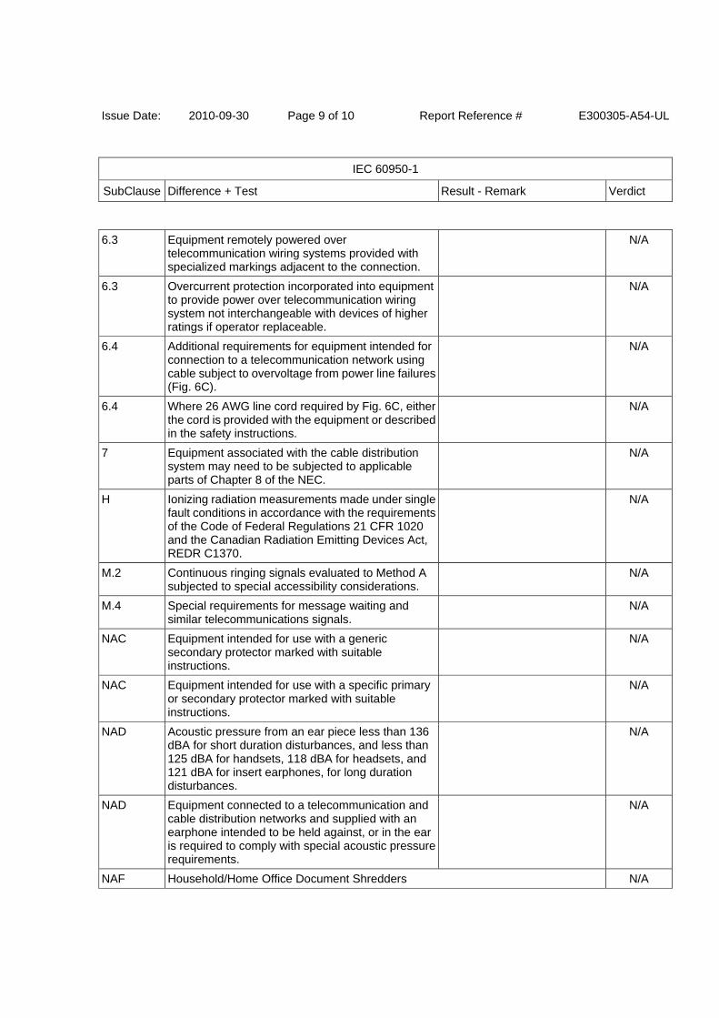
Issue Date: 2010-09-30 Page 9 of 10 Report Reference # E300305-A54-UL
IEC 60950-1
SubClause Difference + Test Result - Remark Verdict
6.3 Equipment remotely powered over telecommunication wiring systems provided with specialized markings adjacent to the connection.
N/A
6.3 Overcurrent protection incorporated into equipment to provide power over telecommunication wiring system not interchangeable with devices of higher ratings if operator replaceable.
N/A
6.4 Additional requirements for equipment intended for connection to a telecommunication network using cable subject to overvoltage from power line failures (Fig. 6C).
N/A
6.4 Where 26 AWG line cord required by Fig. 6C, either the cord is provided with the equipment or described in the safety instructions.
N/A
7 Equipment associated with the cable distribution system may need to be subjected to applicable parts of Chapter 8 of the NEC.
N/A
H Ionizing radiation measurements made under single fault conditions in accordance with the requirements of the Code of Federal Regulations 21 CFR 1020 and the Canadian Radiation Emitting Devices Act, REDR C1370.
N/A
M.2 Continuous ringing signals evaluated to Method A subjected to special accessibility considerations.
N/A
M.4 Special requirements for message waiting and similar telecommunications signals.
N/A
NAC Equipment intended for use with a generic secondary protector marked with suitable instructions.
N/A
NAC Equipment intended for use with a specific primary or secondary protector marked with suitable instructions.
N/A
NAD Acoustic pressure from an ear piece less than 136 dBA for short duration disturbances, and less than 125 dBA for handsets, 118 dBA for headsets, and 121 dBA for insert earphones, for long duration disturbances.
N/A
NAD Equipment connected to a telecommunication and cable distribution networks and supplied with an earphone intended to be held against, or in the ear is required to comply with special acoustic pressure requirements.
N/A
NAF Household/Home Office Document Shredders N/A
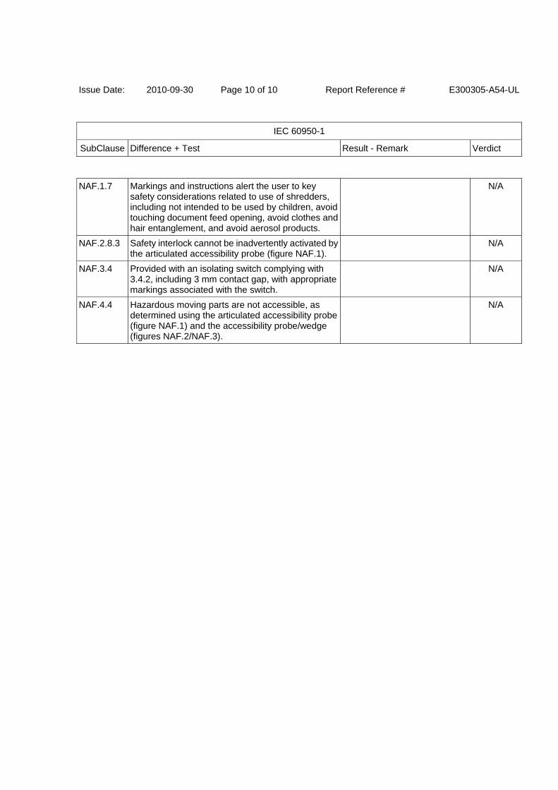
Issue Date: 2010-09-30 Page 10 of 10 Report Reference # E300305-A54-UL
IEC 60950-1
SubClause Difference + Test Result - Remark Verdict
NAF.1.7 Markings and instructions alert the user to key safety considerations related to use of shredders, including not intended to be used by children, avoid touching document feed opening, avoid clothes and hair entanglement, and avoid aerosol products.
N/A
NAF.2.8.3 Safety interlock cannot be inadvertently activated by the articulated accessibility probe (figure NAF.1).
N/A
NAF.3.4 Provided with an isolating switch complying with 3.4.2, including 3 mm contact gap, with appropriate markings associated with the switch.
N/A
NAF.4.4 Hazardous moving parts are not accessible, as determined using the articulated accessibility probe (figure NAF.1) and the accessibility probe/wedge (figures NAF.2/NAF.3).
N/A