Embed Size (px)
Citation preview
The highest dam of the world
in a challenging geological environment
The proposed Rogun 335m high dam, Tajikistan
Paul G. Marinos, Independent consultant
Alessandro Palmieri, Former lead dam specialist, World Bank
Pittsburgh, September 2015
AEG 2015 Annual Meeting

Disclaimer
The views and opinions presented here belong
to the authors and do not reflect
the views and opinions of the World Bank Group.
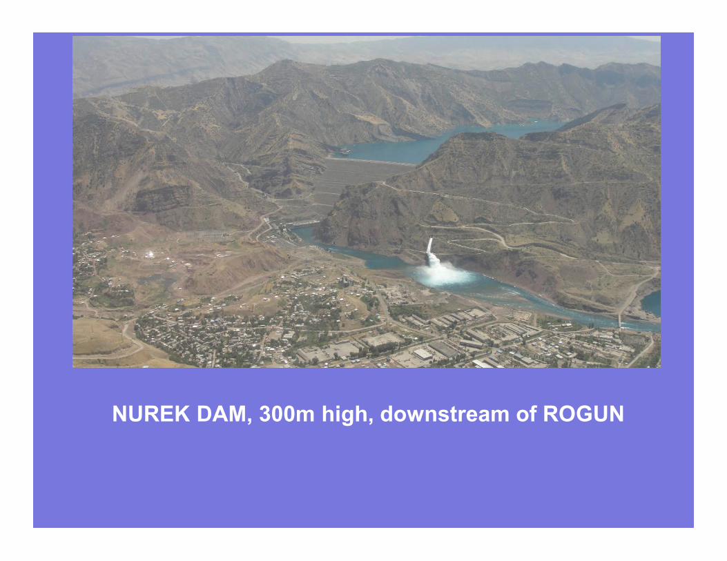
NUREK DAM, 300m high, downstream of ROGUN
Structure of the presentation
1.The project
2.The geological context
3.The site and the selection of the dam type
4.The Power House. A dangerous creep or not?
5.The salt wedge. Assessment and mitigation measures
6.The downstream strange morphology. A huge landslide or not?
PowerTurbines 6
Installed capacity 3600 MW
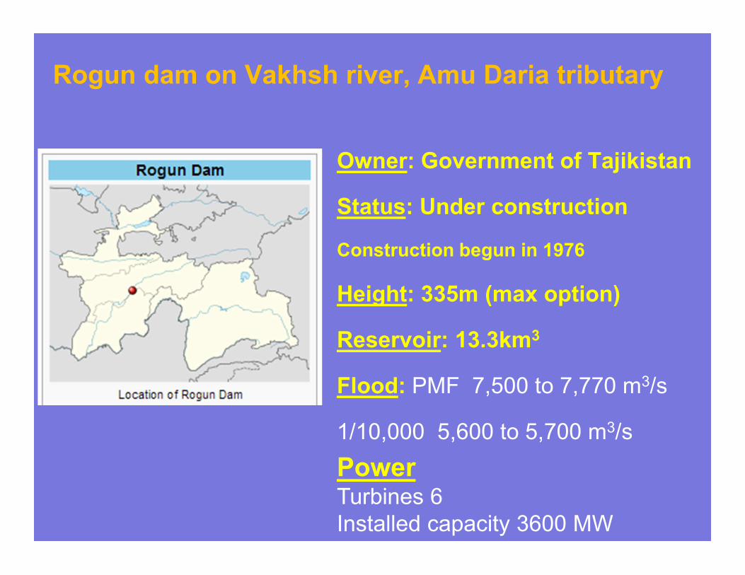
Owner: Government of Tajikistan
Status: Under construction
Construction begun in 1976
Height: 335m (max option)
Reservoir: 13.3km3
Flood: PMF 7,500 to 7,770 m3/s
1/10,000 5,600 to 5,700 m3/s
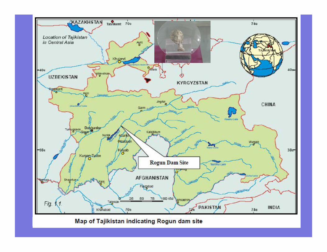
Rogun dam on Vakhsh river, Amu Daria tributary
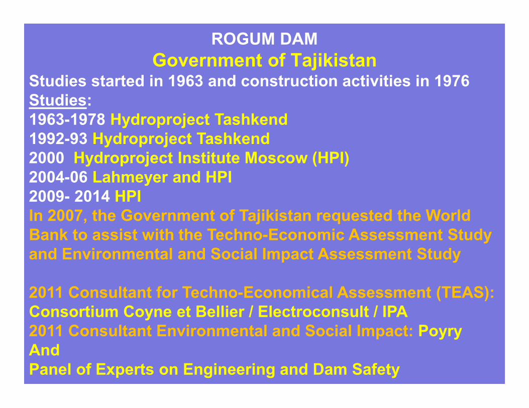
ROGUM DAM
Government of TajikistanStudies started in 1963 and construction activities in 1976
Studies:
1963-1978 Hydroproject Tashkend
1992-93 Hydroproject Tashkend
2000 Hydroproject Institute Moscow (HPI)
2004-06 Lahmeyer and HPI
2009- 2014 HPI
In 2007, the Government of Tajikistan requested the World
Bank to assist with the Techno-Economic Assessment Study
and Environmental and Social Impact Assessment Study
2011 Consultant for Techno-Economical Assessment (TEAS):
Consortium Coyne et Bellier / Electroconsult / IPA
2011 Consultant Environmental and Social Impact: Poyry
And
Panel of Experts on Engineering and Dam Safety

Panel of Experts
Engineering and Dam Safety
Roger Gill, Hydropower
Ljiljana Spacic-Grill, Dam Engineering, Seismic Eng
Paul Marinos, Engineering Geology
Ezio Todini, Hydrology
Gregory Morris, Sedimentology
John Gummer, Energy
To ensure due diligence and international quality standards in studies
To provide independent advice and guidance in the assessment process
To share technical expertise and knowledge
has added significant value to the prospect of developping a
sustainable project at Rogun
1. The geological context
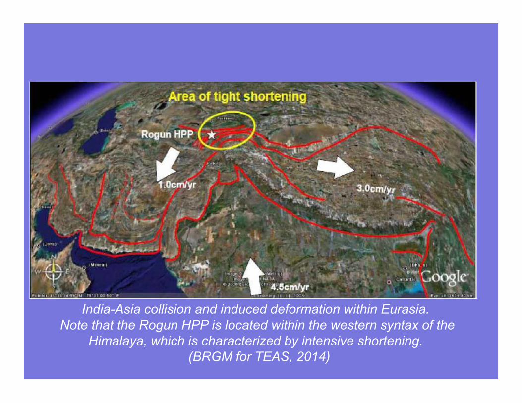
India-Asia collision and induced deformation within Eurasia.
Note that the Rogun HPP is located within the western syntax of the
Himalaya, which is characterized by intensive shortening.
(BRGM for TEAS, 2014)
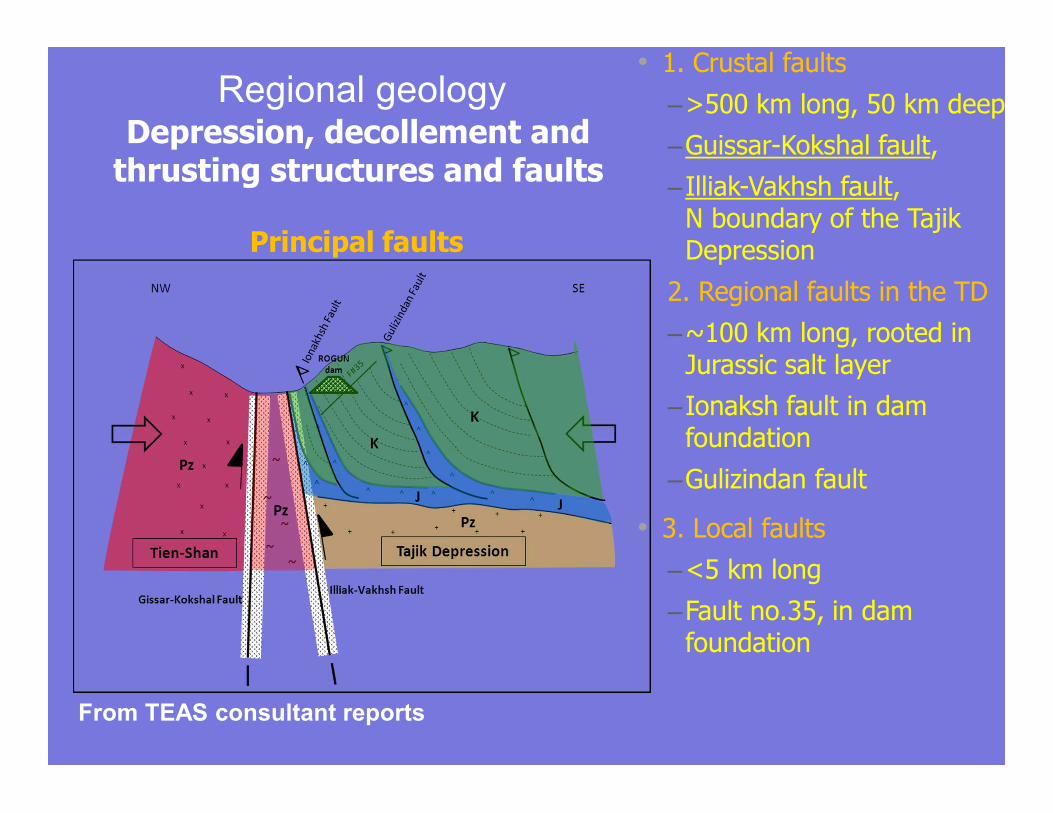
• 1. Crustal faults
–>500 km long, 50 km deep
–Guissar-Kokshal fault,
–Illiak-Vakhsh fault, N boundary of the Tajik Depression
2. Regional faults in the TD
–~100 km long, rooted in Jurassic salt layer
–Ionaksh fault in dam foundation
–Gulizindan fault
• 3. Local faults
–<5 km long
–Fault no.35, in dam foundation
Principal faults
Regional geology
From TEAS consultant reports
Depression, decollement and thrusting structures and faults

2. The site
Geology and selection of the dam type
Design implications
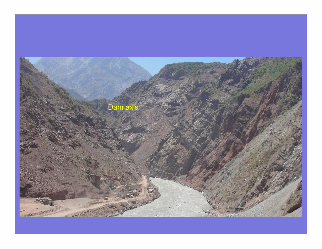
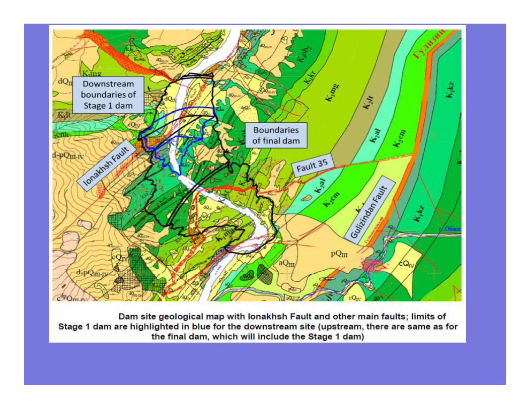
Dam axis
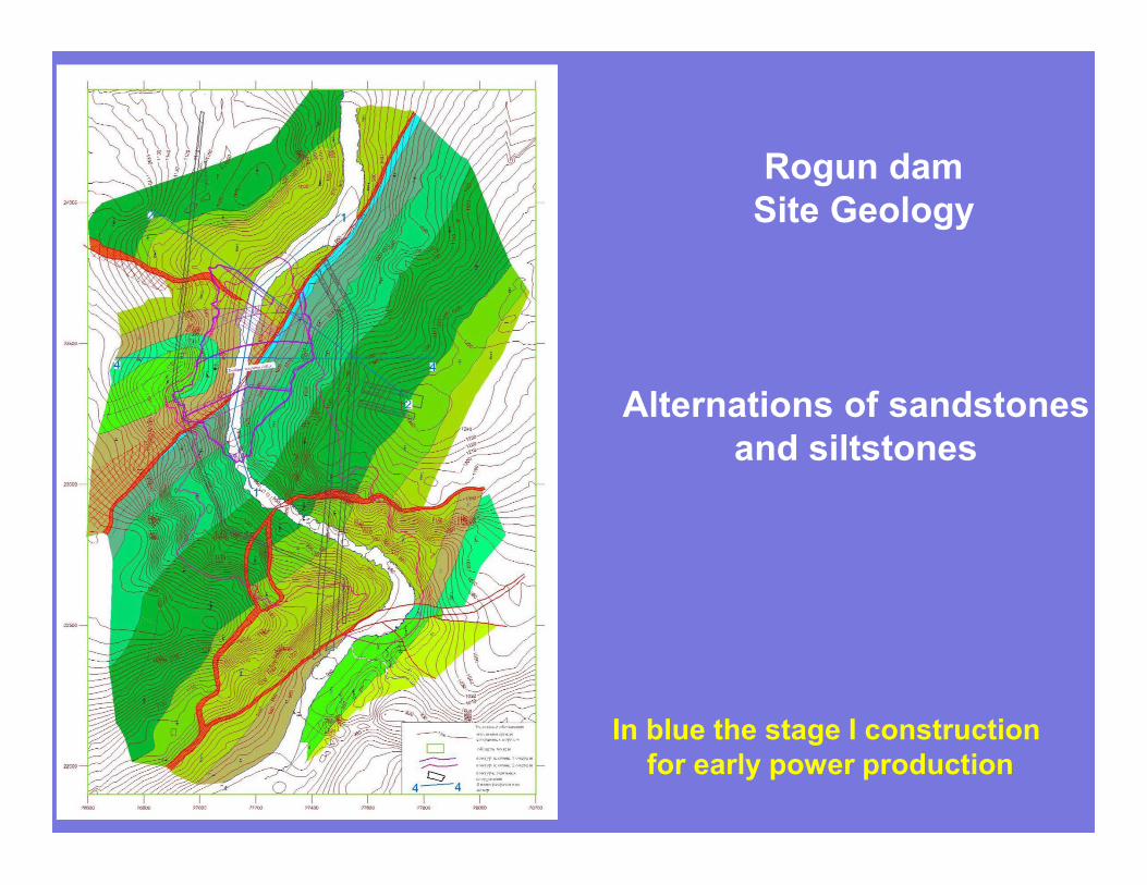
Rogun dam
Site Geology
Alternations of sandstones
and siltstones
In blue the stage I construction
for early power production
•
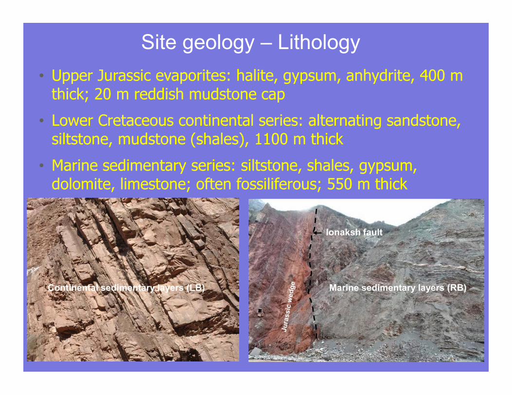
Marine sedimentary layers (RB)Continental sedimentary layers (LB)
Ionaksh fault
• Upper Jurassic evaporites: halite, gypsum, anhydrite, 400 m thick; 20 m reddish mudstone cap
• Lower Cretaceous continental series: alternating sandstone, siltstone, mudstone (shales), 1100 m thick
• Marine sedimentary series: siltstone, shales, gypsum, dolomite, limestone; often fossiliferous; 550 m thick
Site geology – Lithology
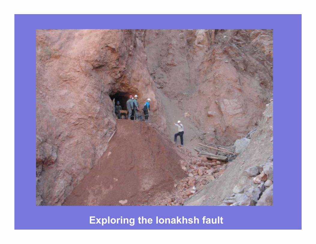
Exploring the Ionakhsh fault
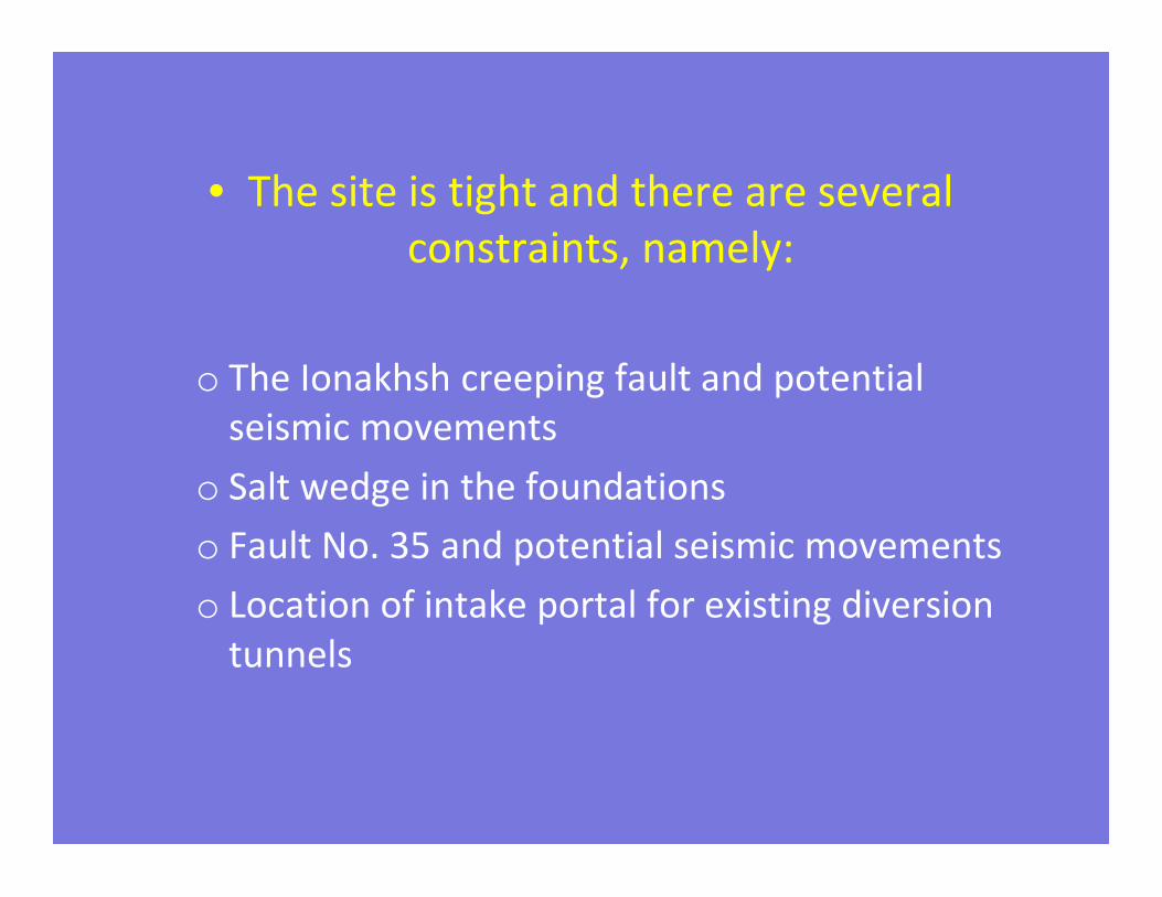
• The site is tight and there are several
constraints, namely:
o The Ionakhsh creeping fault and potential
seismic movements
o Salt wedge in the foundations
o Fault No. 35 and potential seismic movements
o Location of intake portal for existing diversion
tunnels
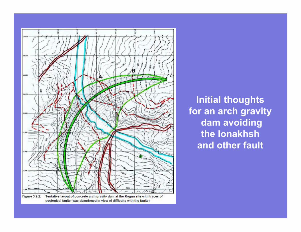
Initial thoughts
for an arch gravity
dam avoiding
the Ionakhsh
and other fault
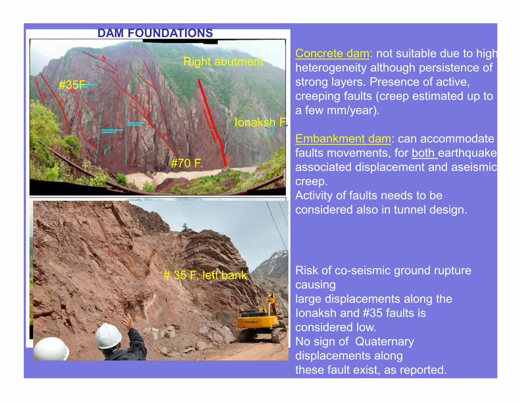
Concrete dam: not suitable due to high
heterogeneity although persistence of
strong layers. Presence of active,
creeping faults (creep estimated up to
a few mm/year).
Embankment dam: can accommodate
faults movements, for both earthquake-
associated displacement and aseismic
creep.
Activity of faults needs to be
considered also in tunnel design.
Risk of co-seismic ground rupture
causing
large displacements along the
Ionaksh and #35 faults is
considered low.
No sign of Quaternary
displacements along
these fault exist, as reported.
Ionaksh F.
#70 F.
# 35 F, left bank
#35F
Right abutment
DAM FOUNDATIONS
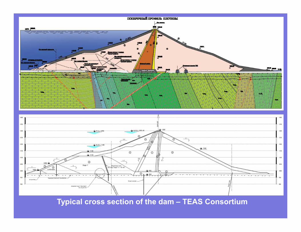
Typical cross section of the dam – TEAS Consortium
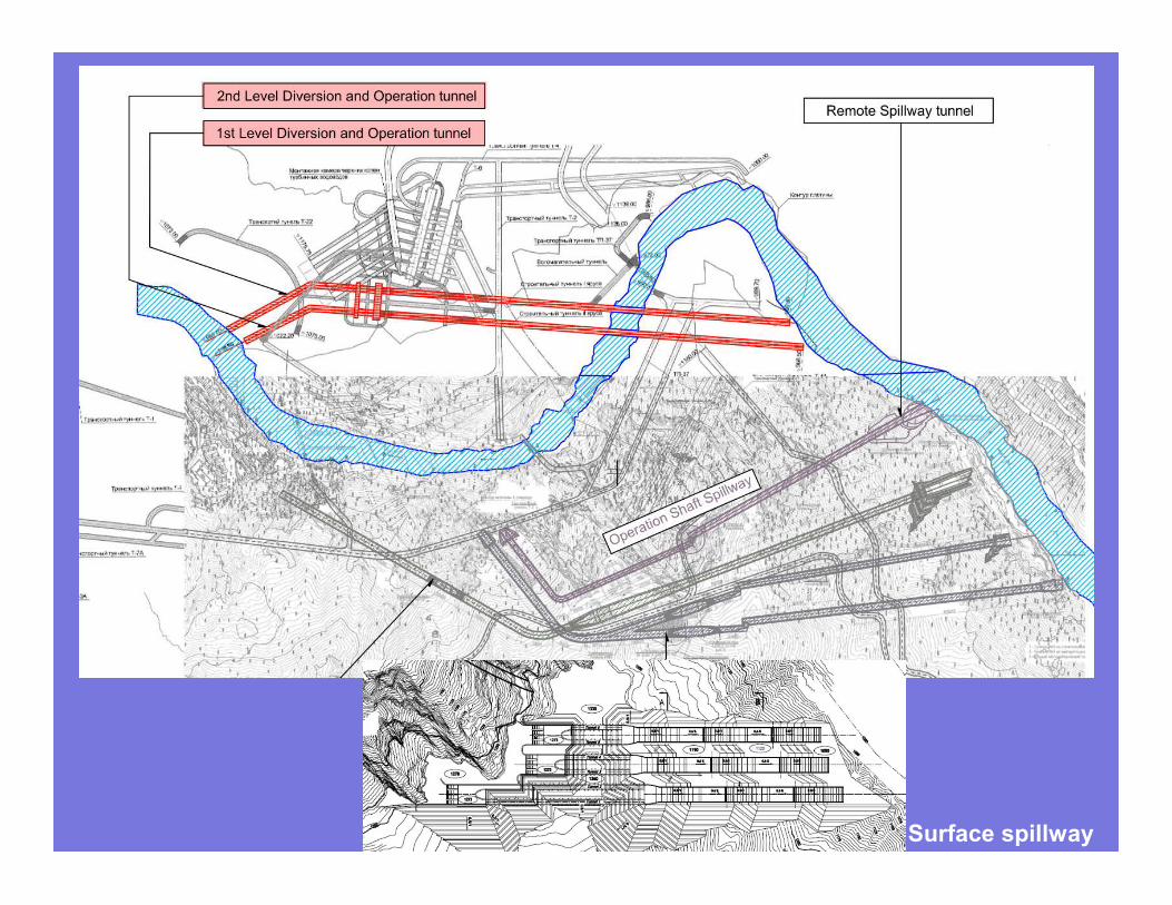
Surface spillway

3. Power House
A dangerous creep or not?
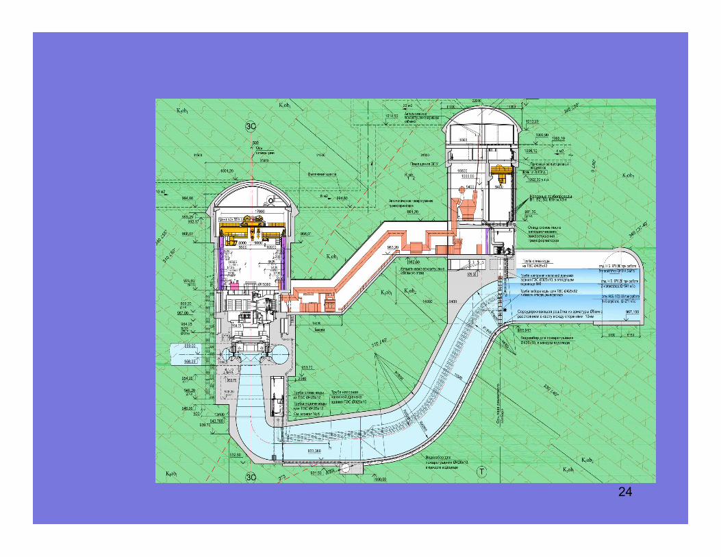
24
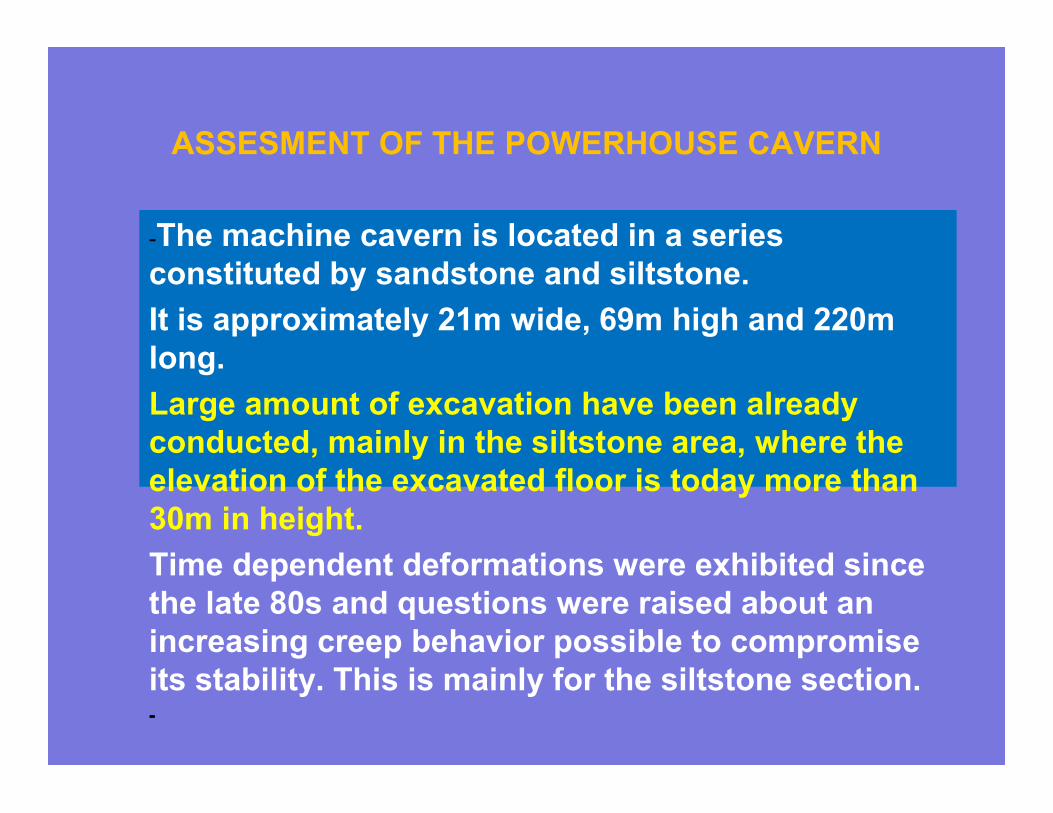
ASSESMENT OF THE POWERHOUSE CAVERN
-The machine cavern is located in a series
constituted by sandstone and siltstone.
It is approximately 21m wide, 69m high and 220m
long.
Large amount of excavation have been already
conducted, mainly in the siltstone area, where the
elevation of the excavated floor is today more than
30m in height.
Time dependent deformations were exhibited since
the late 80s and questions were raised about an
increasing creep behavior possible to compromise
its stability. This is mainly for the siltstone section.-
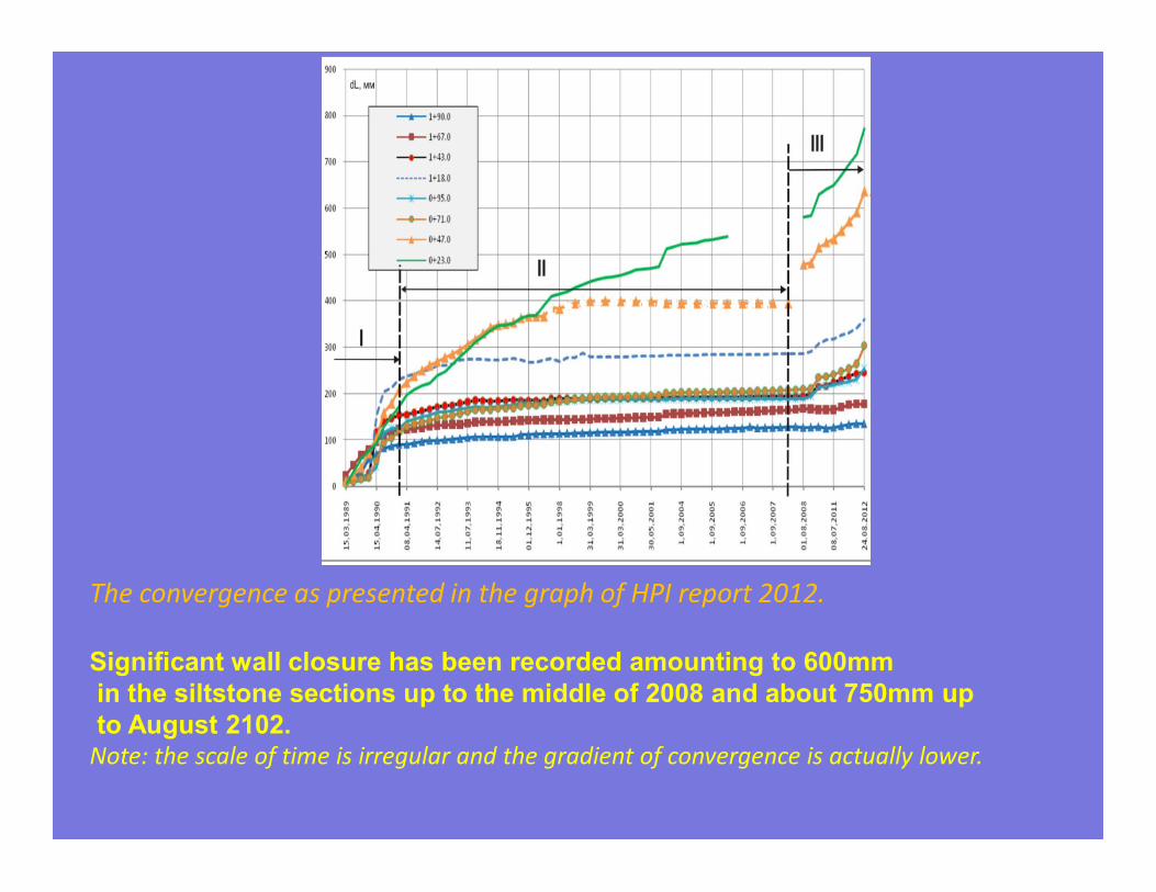
The convergence as presented in the graph of HPI report 2012.
Significant wall closure has been recorded amounting to 600mm
in the siltstone sections up to the middle of 2008 and about 750mm up
to August 2102. Note: the scale of time is irregular and the gradient of convergence is actually lower.
27
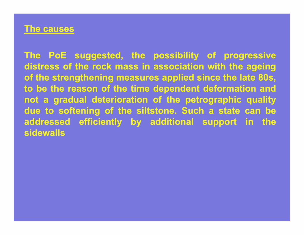
The causes
The PoE suggested, the possibility of progressive
distress of the rock mass in association with the ageing
of the strengthening measures applied since the late 80s,
to be the reason of the time dependent deformation and
not a gradual deterioration of the petrographic quality
due to softening of the siltstone. Such a state can be
addressed efficiently by additional support in the
sidewalls
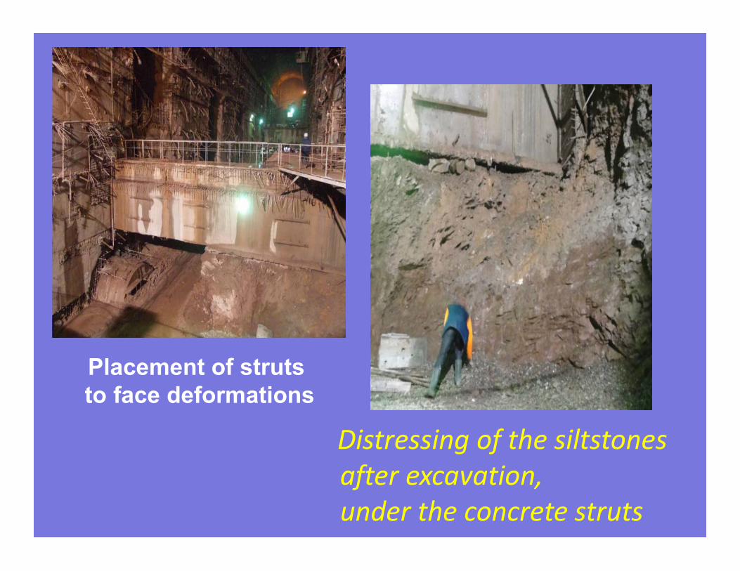
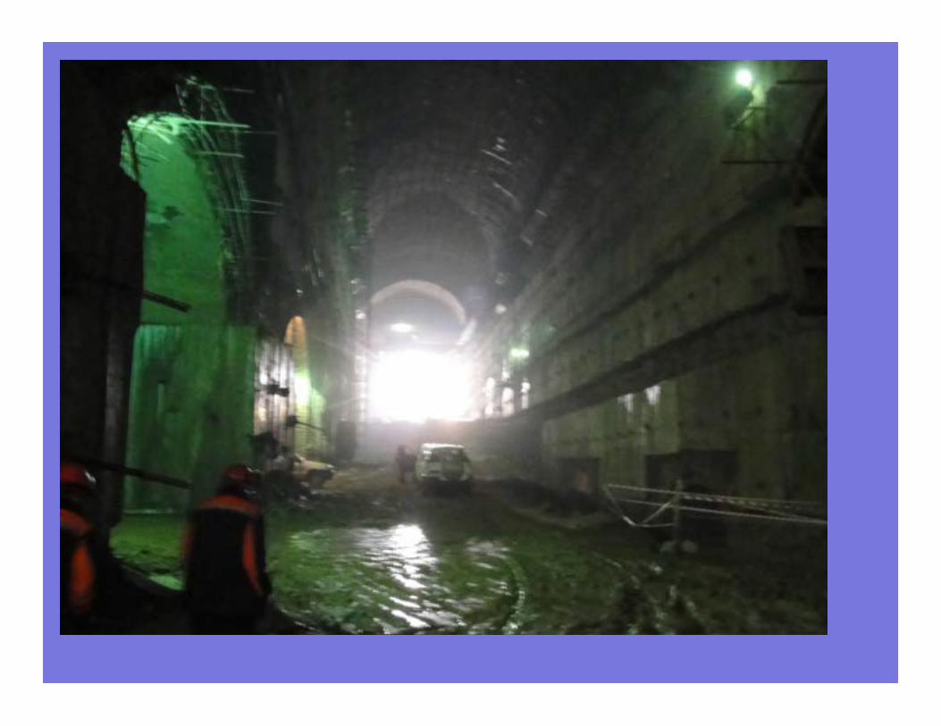
Distressing of the siltstones
after excavation,
under the concrete struts
Placement of struts
to face deformations
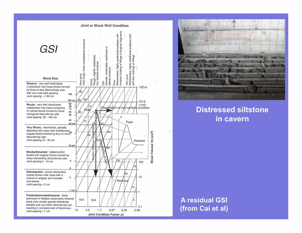
A residual GSI
(from Cai et al)
Distressed siltstone
in cavern
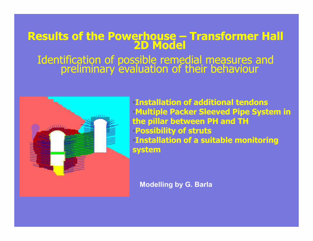
Results of the Powerhouse – Transformer Hall 2D Model
Identification of possible remedial measures and preliminary evaluation of their behaviour
•Installation of additional tendons•Multiple Packer Sleeved Pipe System in the pillar between PH and TH•Possibility of struts •Installation of a suitable monitoring system
Modelling by G. Barla
4. The salt wedge
Assessing conditions and
mitigation measures
A salt wedge exists under the upstream
part of the dam axis along the creeping
Ionakhsh fault which, if not addressed
effectively to prevent dissolution by the
potential hydraulic gradient, could impact
the feasibility of the project.
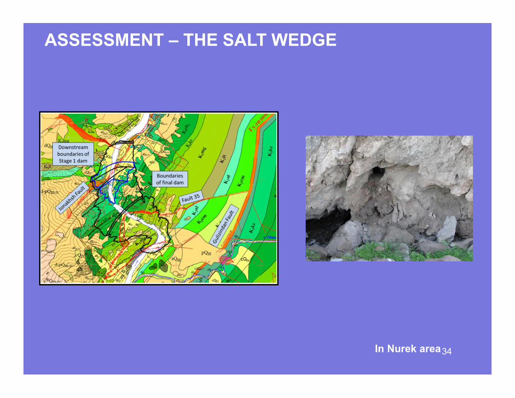
ASSESSMENT – THE SALT WEDGE
34In Nurek area
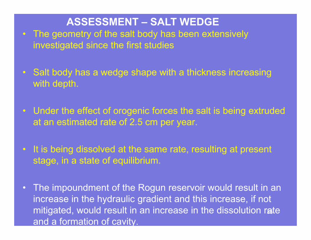
ASSESSMENT – SALT WEDGE• The geometry of the salt body has been extensively
investigated since the first studies
• Salt body has a wedge shape with a thickness increasing
with depth.
• Under the effect of orogenic forces the salt is being extruded
at an estimated rate of 2.5 cm per year.
• It is being dissolved at the same rate, resulting at present
stage, in a state of equilibrium.
• The impoundment of the Rogun reservoir would result in an
increase in the hydraulic gradient and this increase, if not
mitigated, would result in an increase in the dissolution rate
and a formation of cavity.35
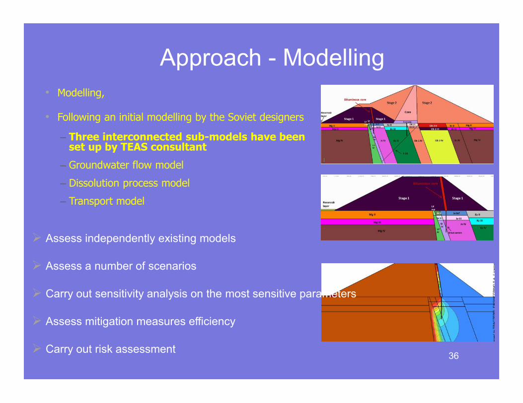
• Modelling,
• Following an initial modelling by the Soviet designers
– Three interconnected sub-models have been set up by TEAS consultant
– Groundwater flow model
– Dissolution process model
– Transport model
Approach - Modelling
36
� Assess independently existing models
� Assess a number of scenarios
� Carry out sensitivity analysis on the most sensitive parameters
� Assess mitigation measures efficiency
� Carry out risk assessment
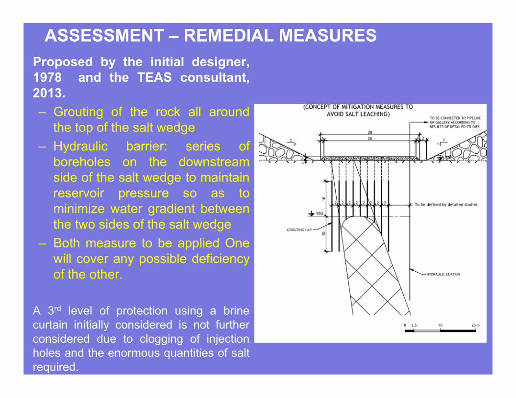
Proposed by the initial designer,
1978 and the TEAS consultant,
2013.
– Grouting of the rock all around
the top of the salt wedge
– Hydraulic barrier: series of
boreholes on the downstream
side of the salt wedge to maintain
reservoir pressure so as to
minimize water gradient between
the two sides of the salt wedge
– Both measure to be applied One
will cover any possible deficiency
of the other.
A 3rd level of protection using a brine
curtain initially considered is not further
considered due to clogging of injection
holes and the enormous quantities of salt
required.
ASSESSMENT – REMEDIAL MEASURES
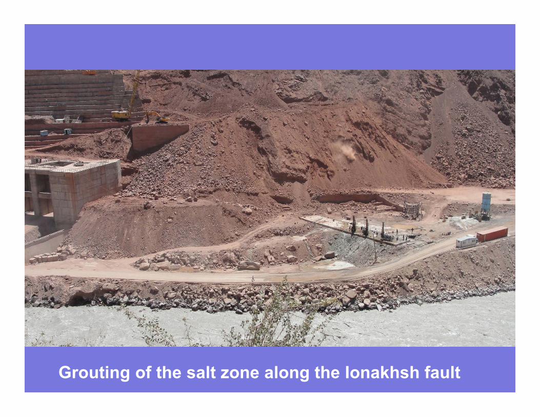
Grouting of the salt zone along the Ionakhsh fault
• If the two mitigation measures would happen to fail or
lose their efficiency, the grouting and hydraulic barrier
would have to be re-implemented.
– Stage 1: the re-grouting and reinstallation of the
hydraulic barrier can be performed from the crest of
the stage 1 dam.
– Stage 2, the only option for re-grouting and hydraulic
barrier restoration would then be to operate from the
banks, above the reservoir water level. This could be
implemented only using directional boring.
RECOMMENDATIONS – MAINTENANCE
5. THE DOWNSTREAM
STRANGE GEOMORPHOLOGY
A HUGE LANDSLIDE OR NOT ?
41
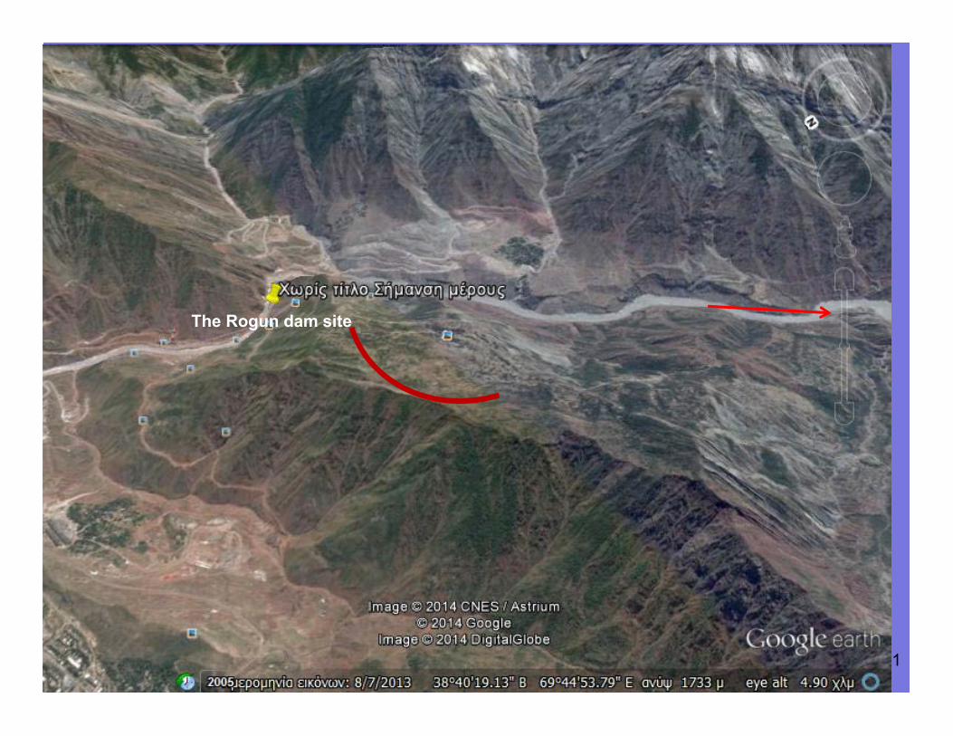
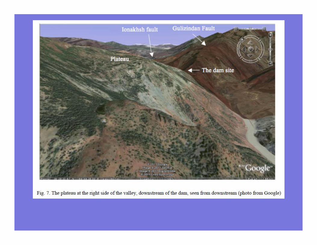
The Rogun dam site
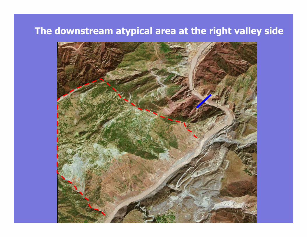
The downstream atypical area at the right valley side
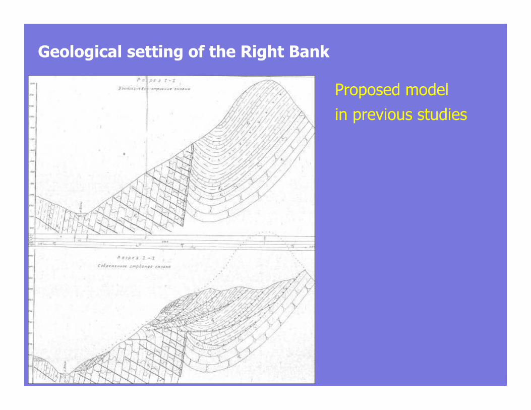
Geological setting of the Right Bank
Proposed model
in previous studies
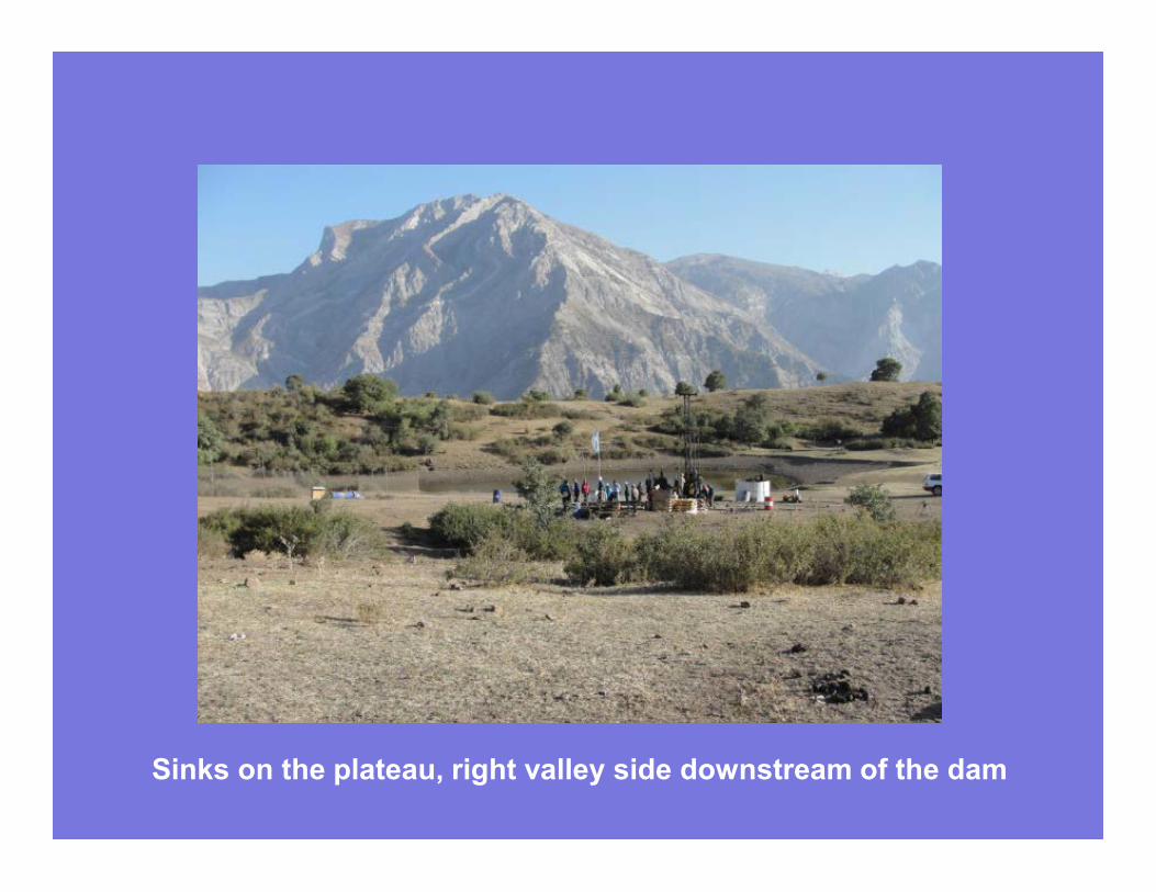
Sinks on the plateau, right valley side downstream of the dam
•
The plateau (elevation about 1700)
with small depressions due to disolution
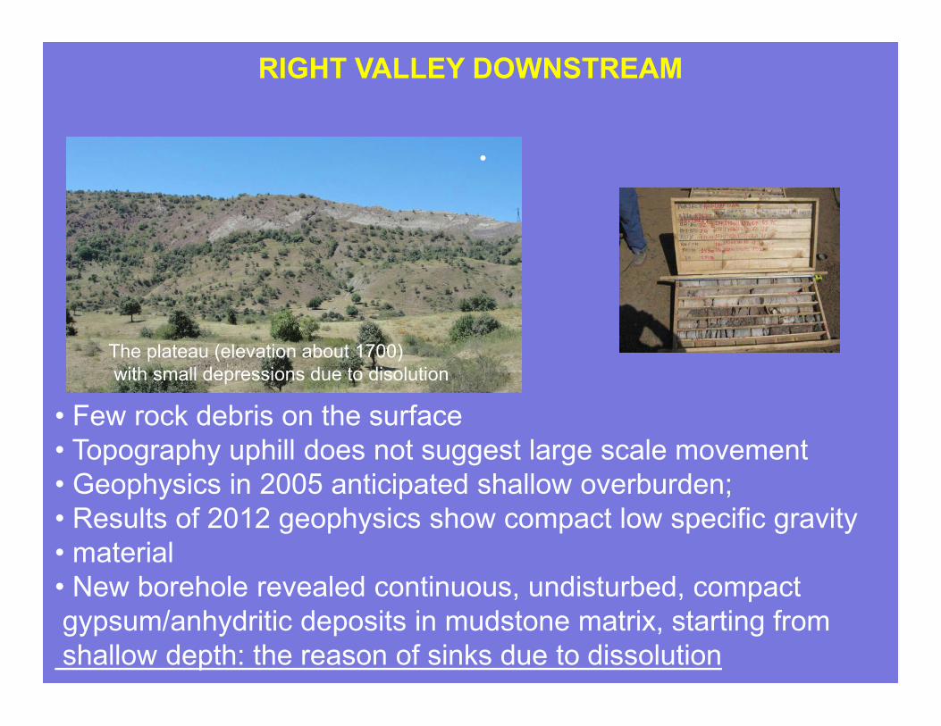
RIGHT VALLEY DOWNSTREAM
• Few rock debris on the surface
• Topography uphill does not suggest large scale movement
• Geophysics in 2005 anticipated shallow overburden;
• Results of 2012 geophysics show compact low specific gravity
• material
• New borehole revealed continuous, undisturbed, compact
gypsum/anhydritic deposits in mudstone matrix, starting from
shallow depth: the reason of sinks due to dissolution
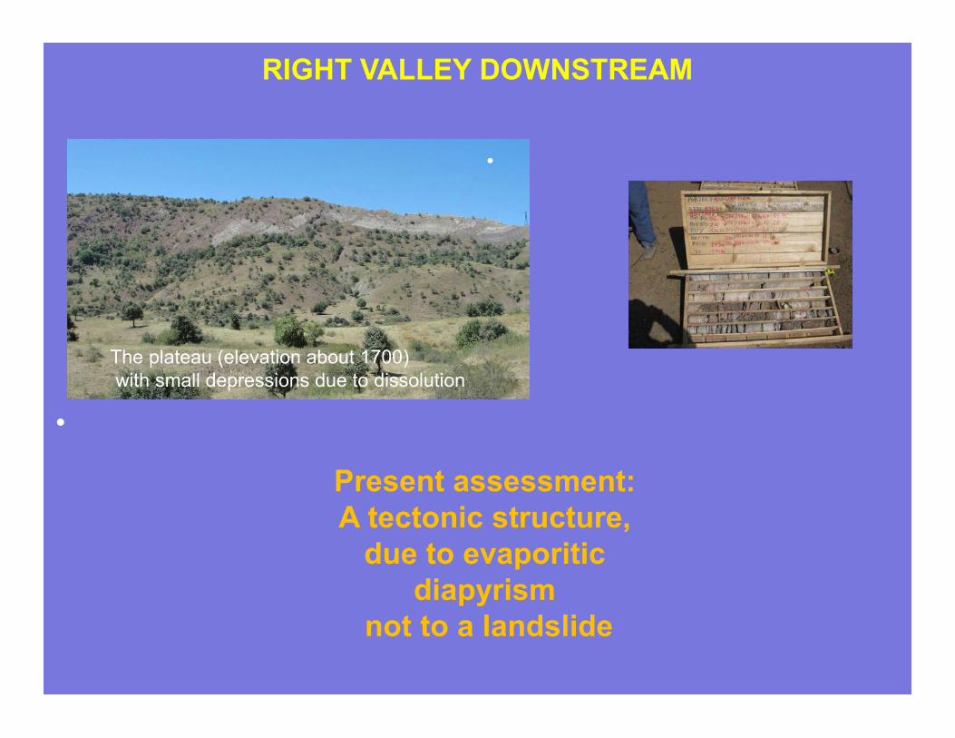
•
The plateau (elevation about 1700)
with small depressions due to dissolution
RIGHT VALLEY DOWNSTREAM
•
Present assessment:
A tectonic structure,
due to evaporitic
diapyrism
not to a landslide
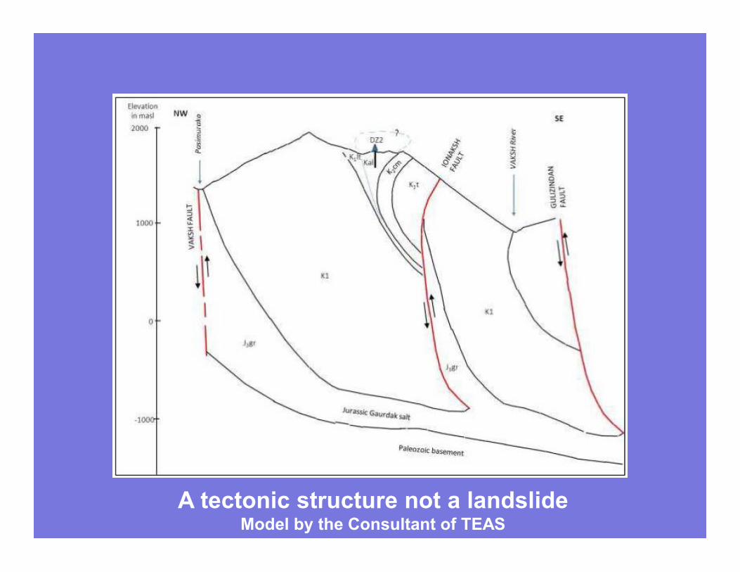
A tectonic structure not a landslideModel by the Consultant of TEAS
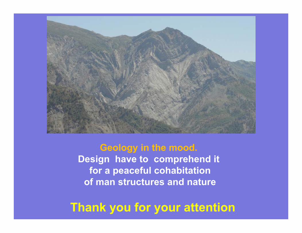
Geology in the mood.
Design have to comprehend it
for a peaceful cohabitation
of man structures and nature
Thank you for your attention

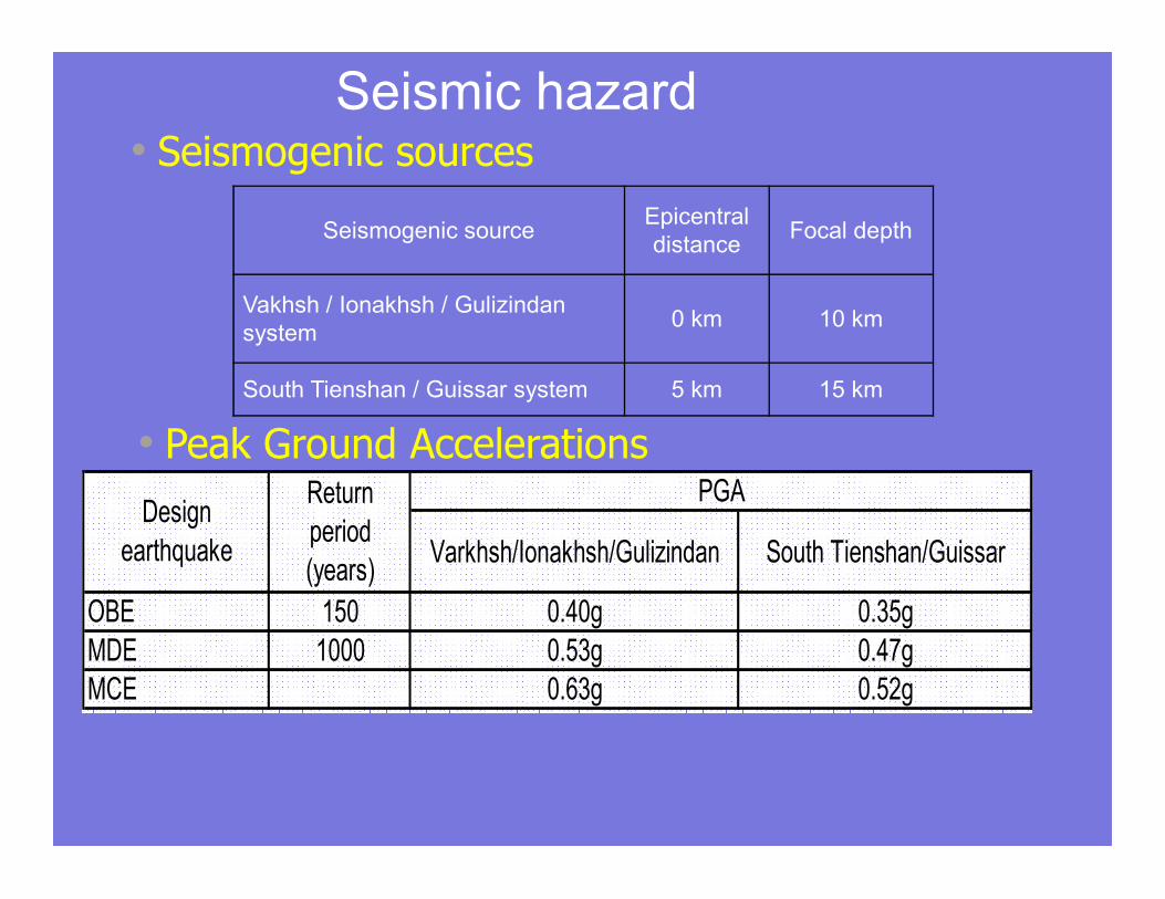
Seismic hazard• Seismogenic sources
Seismogenic sourceEpicentral
distanceFocal depth
Vakhsh / Ionakhsh / Gulizindan
system0 km 10 km
South Tienshan / Guissar system 5 km 15 km
Varkhsh/Ionakhsh/Gulizindan South Tienshan/Guissar
OBE 150 0.40g 0.35g
MDE 1000 0.53g 0.47g
MCE 0.63g 0.52g
Design
earthquake
Return
period
(years)
PGA
• Peak Ground Accelerations
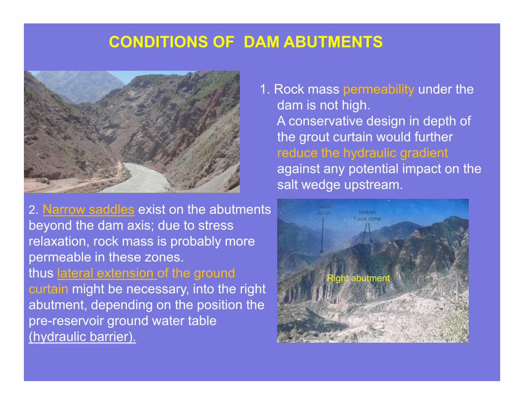
CONDITIONS OF DAM ABUTMENTS
2. Narrow saddles exist on the abutments
beyond the dam axis; due to stress
relaxation, rock mass is probably more
permeable in these zones.
thus lateral extension of the ground
curtain might be necessary, into the right
abutment, depending on the position the
pre-reservoir ground water table
(hydraulic barrier).
Right abutment
1. Rock mass permeability under the
dam is not high.
A conservative design in depth of
the grout curtain would further
reduce the hydraulic gradient
against any potential impact on the
salt wedge upstream.
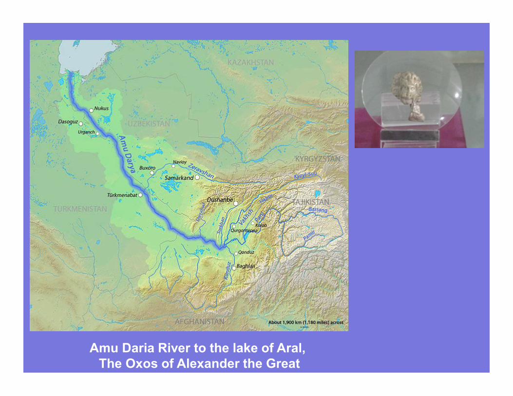
Amu Daria River to the lake of Aral,
The Oxos of Alexander the Great
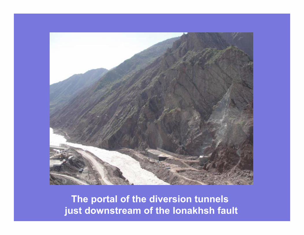
The portal of the diversion tunnels
just downstream of the Ionakhsh fault
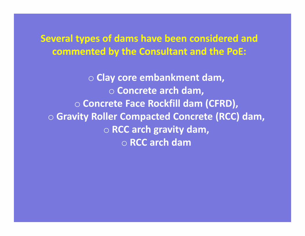
Several types of dams have been considered and
commented by the Consultant and the PoE:
o Clay core embankment dam,
o Concrete arch dam,
o Concrete Face Rockfill dam (CFRD),
o Gravity Roller Compacted Concrete (RCC) dam,
o RCC arch gravity dam,
o RCC arch dam
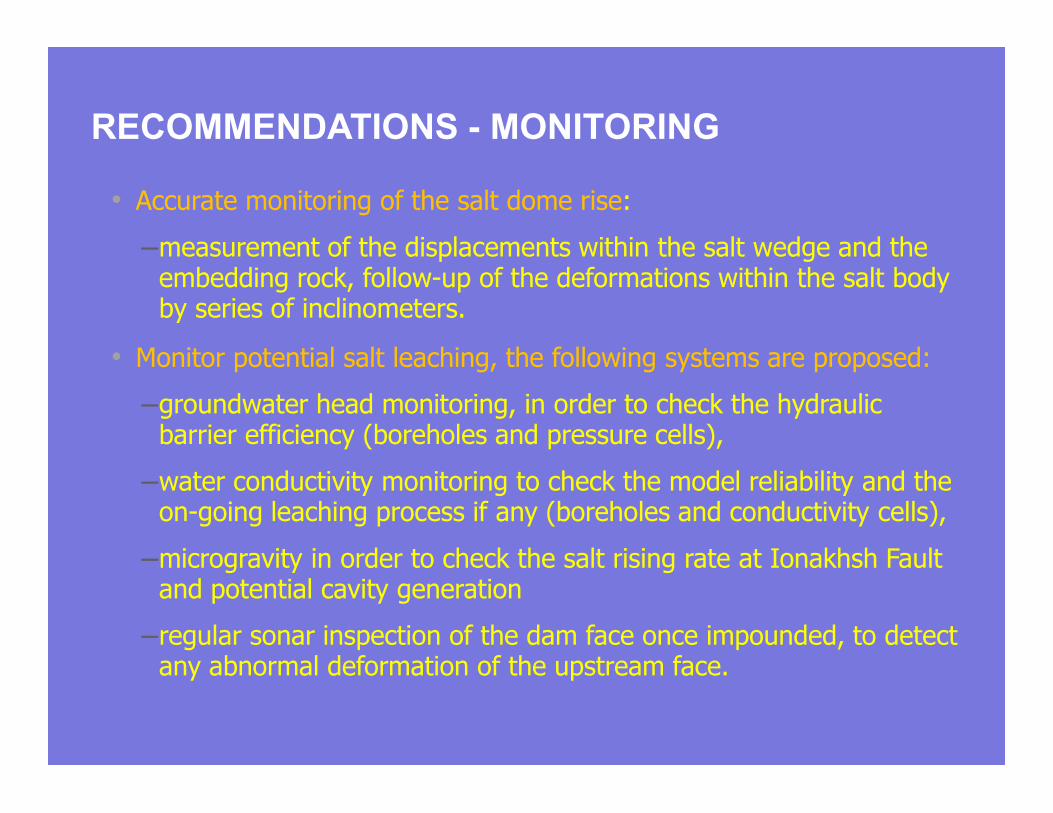
RECOMMENDATIONS - MONITORING
• Accurate monitoring of the salt dome rise:
–measurement of the displacements within the salt wedge and the embedding rock, follow-up of the deformations within the salt body by series of inclinometers.
• Monitor potential salt leaching, the following systems are proposed:
–groundwater head monitoring, in order to check the hydraulic barrier efficiency (boreholes and pressure cells),
–water conductivity monitoring to check the model reliability and the on-going leaching process if any (boreholes and conductivity cells),
–microgravity in order to check the salt rising rate at Ionakhsh Fault and potential cavity generation
–regular sonar inspection of the dam face once impounded, to detect any abnormal deformation of the upstream face.
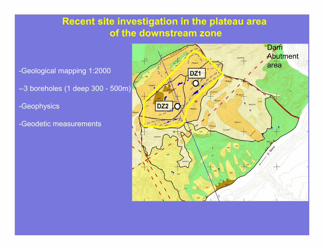
Recent site investigation in the plateau area
of the downstream zone
-Geological mapping 1:2000
--3 boreholes (1 deep 300 - 500m)
-Geophysics
-Geodetic measurements
Dam
Abutment
area
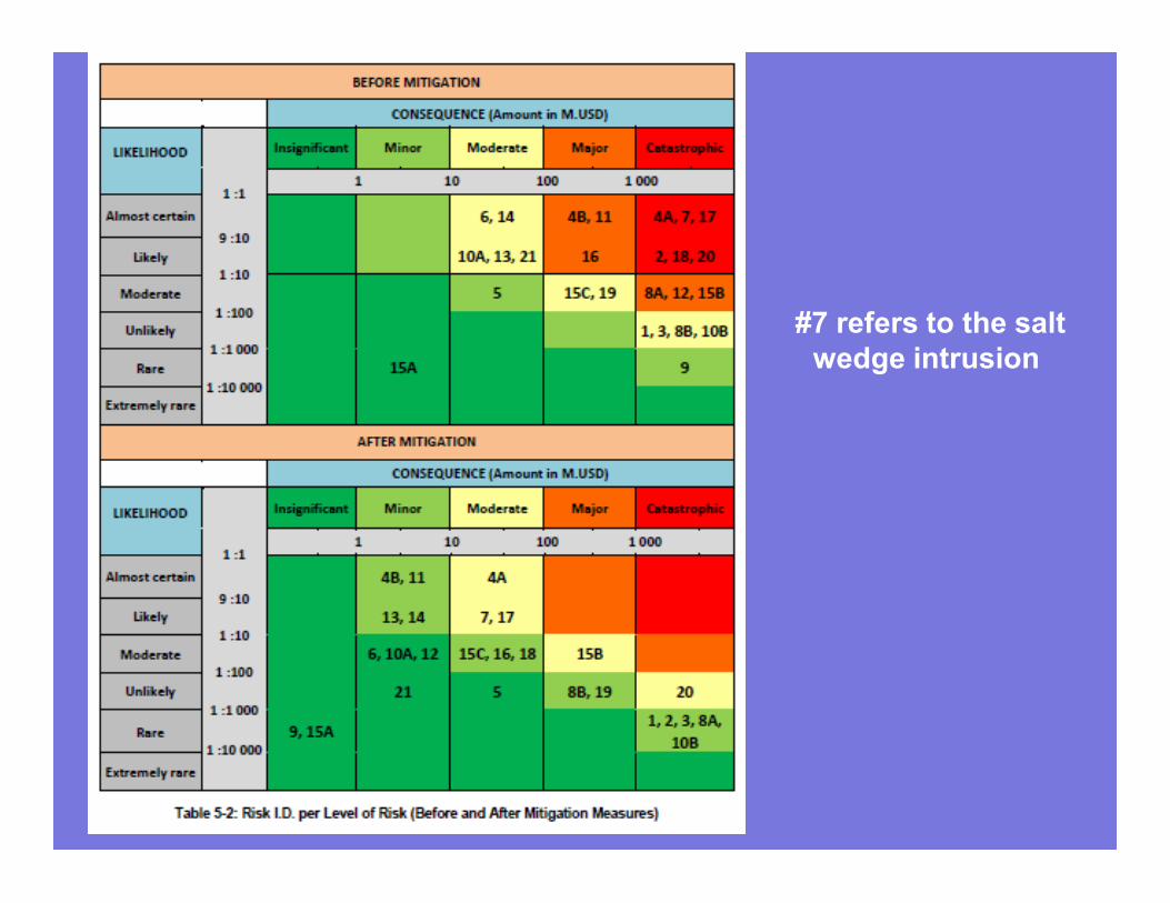
#7 refers to the salt
wedge intrusion