Embed Size (px)
Citation preview

Intended for NSN Link
Project no. 61031746
Date 14 November 2013
UK - NORWAY ELECTRICITY INTERCONNECTOR (NSN LINK) FLOOD RISK ASSESSMENT

Revision History
Revision Date Purpose / Status
Document Ref. Comments
V1 13/11/2013 Draft 61031746/E01
V2 14/11/2013 Final 61031746/E02
Prepared By Reviewed By Approved By
Carl Bailey Luke Strickland Luke Strickland
Environmental Consultant Associate Associate
Ramboll Christchurch House 30 Waterloo Street Victoria Square Birmingham B2 5TJ United Kingdom tel +44 (0)121 230 1650 fax +44 (0)121 230 1675 [email protected]

UK - NORWAY ELECTRICITY INTERCONNECTOR (NSN LINK) FLOOD RISK ASSESSMENT
CONTENTS
1. Introduction .............................................................................................................. 1 2. Site Context .............................................................................................................. 2 3. Assessment of New Development ................................................................................. 8 4. Conclusions ............................................................................................................. 11
TABLES
Table 2.1: Summary of Geology by Site Section...................................................................... 3 Table 2.2: Summary of Surface Water Features by Site Section ................................................ 4 Table 2.3: Surface Water Flood Risk ...................................................................................... 6 Table 2.4: Flood Risk Summary ............................................................................................ 7
APPENDICES
Appendix A: Site Location Plan
Appendix B: Proposed Site Layout
Appendix C: Converter Station Layout
Appendix D: SFRA Maps

UK - NORWAY ELECTRICITY INTERCONNECTOR (NSN LINK) FLOOD RISK ASSESSMENT
1
1. INTRODUCTION
1.1.1. Ramboll has been commissioned by The Environment Partnership (TEP) to undertake a Flood Risk Assessment (FRA) to inform the Environmental Impact Assessment (EIA) and planning application for the onshore section of the UK - Norway Electricity Interconnector (NSN Link) at Cambois, north of Blyth, Northumberland.
1.1.2. The information used to prepare this report includes:
i. The Northumberland County Council Strategic Flood Risk Assessment (SFRA) April 2010, prepared by Scott Wilson1;
ii. British Geological Survey (BGS) maps2;
iii. The Environment Agency (EA) online database of indicative floodplain and hydrogeological maps3;
iv. Ordnance Survey 1:10,000 scale mapping; and
v. Northumbrian Water Site Enquiry Plans4.
1.1.3. Ramboll cannot accept liability for the accuracy or otherwise of any information derived from third party sources.
1.1.4. This FRA has been carried out in accordance with the National Planning Policy Framework (NPPF)5. It is to be used to assist the Environment Agency (EA) and Northumberland County Council (NCC) when considering flooding issues that might be associated with the proposed development through the planning application, and to inform the EIA.
1.1.5. The scope of this report is as follows:
i. An assessment of the flood risk to the site based upon the available flood maps provided by the EA and included in the SFRA;
ii. An assessment of the impact of the new development in terms of surface water runoff;
iii. Proposals to mitigate any residual flood risks to/from the development (if any) and to inform the design, including any opportunities for sustainable drainage.
1 Scott Wilson (2010) Northumberland County Council Level 1 Strategic Flood Risk Assessment [online] Available: http://www.northumberland.gov.uk/default.aspx?page=11924 [date accessed: 11/10/2013] 2 British Geological Survey (2013) Geology of Britain Viewer [online] Available: http://www.bgs.ac.uk/data/mapViewers/home.html [date accessed: 11/10/2013] 3 The Environment Agency Interactive Maps [online] Available: http://www.environment-agency.gov.uk/homeandleisure/37793.aspx [date accessed: 11/10/2013] 4 Northumbrian Water (2013) Site Enquiries for Brock Lane and Wembley Gardens. 5 Department for Communities and Local Government (2012) National Planning Policy Framework [online] Available: https://www.gov.uk/government/publications/national-planning-policy-framework--2 [date accessed: 12/11/2013]

UK - NORWAY ELECTRICITY INTERCONNECTOR (NSN LINK) FLOOD RISK ASSESSMENT
2
2. SITE CONTEXT
2.1. Site Location
2.1.1. The site comprises the cable routes and a converter station associated with NSN Link located broadly between the River Wansbeck and River Blyth estuaries, close to the villages of Cambois and East Sleekburn in Northumberland. This area of land is bordered by:
• the estuary of the River Wansbeck to the north; • a former coal storage yard and railway sidings to the south and east; • the Sleek Burn and the estuary of the River Blyth to the south; and • the A189 trunk road to the west.
2.1.2. The proposed cable route connects to the Blyth substation, centred at OS National Grid Reference (NGR) 429985 583070. It is proposed that landfall for the cable route will be made at Cambois Slipway, close to the south bank of the mouth of the River Wansbeck.
2.1.3. The Site Location is shown in Appendix A.
2.2. Site Description and Layout
2.2.1. The project comprises the High Voltage Direct Current (HVDC) buried cables from the landfall location where the cables come ashore to the proposed converter station to be located on land to the north of Brock Lane, centred at approximate OS NGR 429371, 583700. It also includes High Voltage Alternating Current (HVAC) buried cables from the converter station to Blyth Substation. The proposed project is shown in Appendix B.
2.2.2. From the landfall the cable route heads in a westerly direction crosses the coastal cliffs behind the beach and then extends over generally level agricultural land, past a Water Treatment Works, until the point where it meets Wembley Gardens road and the mineral railway. From here the cable route runs south and passes through an industrial park (Ferguson’s Business Park) along a wide track which is also a Public Right of Way between developments. The cable route continues into an area of level agricultural land, which will be the site of the converter station. From the converter station the HVAC cable route continues across agricultural land to the south east and crosses the Brock Lane to reach the Blyth sub-station which is located at the shore of the Blyth Estuary including the mouth of the Sleek Burn tidal creek. The total length of the route is approximately 2.5km. Overall, the land along the route is generally level with an altitude of 5m to 12m above sea level. The route crosses a series of small drainage ditches along its length and these are described in more detail in 2.5 Hydrological Setting below.
2.2.3. Due to the length of the cable route, it has been divided into sections for assessment. The sections are numbered one to seven, from the landfall location to Blyth Substation and are shown in Appendix B. The proposed Converter Station location, also shown in Appendix B, is considered within this report as a separate section, and the layout is shown in Appendix C.

UK - NORWAY ELECTRICITY INTERCONNECTOR (NSN LINK) FLOOD RISK ASSESSMENT
3
2.2.4. At present, the cable route is indicative and will be further refined as the design develops. Commentary is made within this report where it is considered that flood risk presents a significant constraint to cable routing.
2.3. Geological Setting
2.3.1. BGS mapping shows the site to be located on Pennine Middle Coal Measures formation bedrock, comprising predominantly sandstone, with mudstone and siltstone. There is a dyke shown orientated east-west that cross the cable route, formed from igneous intrusions of microgabbro.
2.3.2. Superficial deposits are shown beneath the entire site, predominantly comprising glacial till, with some blown sand, and marine deposits (sand and gravel) at the landfall location. Table 2.1 below summarises the geological formations by site section.
Table 2.1: Summary of Geology by Site Section
Section Bedrock Superficial
1 Pennine middle coal measures formation – Interbedded mudstone, siltstone, sandstone with coal seams
Blown sand/beach deposits, possibly underlain by glacial till
2 to 7 Glacial till
Converter Station Glacial till
2.4. Hydrogeological Setting
2.4.1. Definitions for the aquifer types are provided below based on the EA website:
• Principal Aquifer: “layers of rock or drift deposits that have high intergranular and/ or fracture permeability – meaning they usually provide a high level of water storage. They may support water and/ or river base flow on a strategic scale.”
• Secondary A aquifer: “permeable layers capable of supporting water supplies at a local rather than strategic scale, and in some cases forming an important source of base flow to rivers.”
• Secondary B aquifer: “predominantly lower permeability layers which may store and yield limited amounts of groundwater due to localised features such as fissures, thin permeable horizons and weathering. These are generally the water-bearing parts of the former non-aquifers.”
• Secondary ‘undifferentiated’ aquifer: “it has not been possible to attribute either category A or B to a rock type. In most cases, this means that the layer in question has previously been designated as both minor and non-aquifer in different locations due to the variable characteristics of the rock type.”
2.4.2. The bedrock beneath the site is defined as a Secondary A Aquifer according to the EA website.
2.4.3. The windblown sand and beach deposits beneath Section 1 are also defined as a Secondary A aquifer.
2.4.4. The glacial till beneath the remainder of the route is defined as a non-aquifer, and will likely comprise low permeability clay. There may be lenses of sand and gravel within the glacial till that may hold groundwater but these will not constitute a significant aquifer.

UK - NORWAY ELECTRICITY INTERCONNECTOR (NSN LINK) FLOOD RISK ASSESSMENT
4
2.5. Hydrological Setting
2.5.1. Broadly, the site is located between two small estuaries and the North Sea. The river Wansbeck lies to the north and to the south lies Sleek Burn, a branch of the Blyth Estuary. The North Sea coast is formed of dunes to the south and low cliffs in the north.
2.5.2. Located within Section 3 of the cable route, Maw Burn is a small watercourse, which appears to have been heavily modified during previous land uses. It is culverted beneath the A189, and again in small sections for the entrance roads associated with Fergusons Business Park, and beneath the former coal stockyard. Through consultation with NCC it has been confirmed that Maw Burn is under riparian ownership.
2.5.3. A watercourse marked as Cow Gut is shown on OS mapping, flowing to the south of the motorcycle track before crossing the former storage yard and railway sidings in culvert. This has been identified as an Ordinary Watercourse under NCC jurisdiction.
2.5.4. Table 2.2 below summarises the surface water features at or near the site.
Table 2.2: Summary of Surface Water Features by Site Section
Section Surface Water Feature Distance
1 North Sea 0m
2 None shown N/A
3 Maw Burn (riparian watercourse, partially culverted) On site
4 None shown N/A
5 Cow Gut (Ordinary Watercourse, heavily modified) <5m
6 Cow Gut (Ordinary Watercourse, heavily modified)
Pond within former storage yard
On site
100m
Converter Station
Cow Gut <250m
7 Unnamed ditches
Sleek Burn (Primary River, Estuary)
On site
<100m
2.6. Existing Drainage
2.6.1. Northumbrian Water plans show there to be existing combined sewers located on Brock Lane, approximately 230m east of the point at which the cable route crosses the road. Only road drainage and existing distribution water mains are shown on site at this location.
2.6.2. On the plans showing Wembley Gardens, there are three parallel pipelines located to the north of the road within agricultural fields. These comprise the following:
i. An overflow interceptor pipe which is likely to intercept and convey combined sewage overflow from Cambois to the sewage works (overflow would originally have been discharged directly to the sea); and
ii. Two pipes associated with the conveyance of treated sewage to an outfall pipe on the North Sea coast.

UK - NORWAY ELECTRICITY INTERCONNECTOR (NSN LINK) FLOOD RISK ASSESSMENT
5
2.6.3. There is also a sewage pipe linking the Synpac works (located west of the A189) to an outfall at North Cambois which runs parallel to the above mentioned pipes at the crossing point with the project. There are additional combined sewers parallel with the railway and road. The cable route crosses all of these features.
2.6.4. A network of separate surface water drains and sewers are shown within Ferguson’s Business Park. These discharge to a combined sewer towards the north of the sewage works.
2.6.5. It is anticipated that land drainage systems will be present in agricultural land at the site but the extent or layout of land drainage cannot be confirmed at this time.
2.7. Existing Flood Risk
Fluvial and Tidal
2.7.1. The EA indicative flood plain maps identify areas in England and Wales at risk of flooding by allocating them into flood risk zones.
2.7.2. The flood risk zones shown on the flood maps are defined in Table 2 of the Technical Guidance to the NPPF and these are:
Zone 1: Low Probability
According to the NPPF, land in this zone is considered to have less than 1 in 1000 annual probability of river or sea flooding in any year. This is < 0.1%.
Zone 2: Medium Probability
According to the NPPF, land in this zone is considered to have between a 1 in 100 and 1 in 1000 annual probability of river flooding in any year (between 1% and 0.1%) or between a 1 in 200 and 1 in 1000 annual probability of sea flooding in any year (0.5%-0.1%).
Zone 3a: High Probability
According to the NPPF, land in this zone is considered to have a 1 in 100 or greater annual probability of river flooding in any year (>1%) or a 1 in 200 or greater annual probability of flooding from the sea in any year (>0.5%).
Zone 3b: The Functional Floodplain
According to the NPPF, land in this zone is used for water flow or storage in times of flood. This flood zone should be identified by a Strategic Flood Risk Assessment (SFRA). It is considered to have a 1 in 20 or greater chance of river flooding in any year which is > 5%. Another probability however can also be agreed between the LPA and the E.A.
2.7.3. The EA indicative flood map for the site shows that no part of the cable routes or the converter station site are located within an area at risk of flooding from rivers and sea. This corresponds to Flood Zone 1, where the flood risk is assessed as having less than a 1 in 1000 year return period. Therefore, the entire scheme is at low risk of fluvial/tidal flooding.
Surface Water and Sewer Drainage Risk
2.7.4. The SFRA shows that parts of the cable route and the converter station site are susceptible to surface water flooding. The surface water flood susceptibility specific to
UK - NORWAY ELECTRICITY INTERCONNECTOR (NSN LINK) FLOOD RISK ASSESSMENT
6
each section of the route is summarised in Table 2.4 below. The surface water flood risk map from the SFRA is included within Appendix D for reference.
Table 2.3: Surface Water Flood Risk
Section Surface Water Flood Risk Notes
1 None N/A
2 Less/Intermediate Low lying land within agricultural fields
3 Less/Intermediate Low ground adjacent to railway/road crossing
4 Less/Intermediate Localised section of road within business park
5 Intermediate/More Low lying land adjacent to hedgerow along eastern edge of motorbike track.
6 Less/Intermediate Low lying land within agricultural fields
Converter Station
Intermediate/Higher Wide area of intermediate susceptibility covering land to the east of the converter station site with a small localised area at higher risk within the centre of this location.
7 Less Small, localised areas of agricultural land
2.7.5. The SFRA provides mapping to show areas where the drainage network (sewers) may be susceptible to being overwhelmed during periods of high intensity rainfall. These maps, which are included within Appendix D for reference, show that the site is located within an area at intermediate susceptibility to sewer and storm water flooding.
Groundwater Flood Risk
2.7.6. The SFRA does not provide an assessment of the risk of flooding from groundwater. However, taking into account the underlying geology at the site this is anticipated to be low within the glacial till.
2.7.7. There will be limited risk of groundwater flooding within the beach and windblown sand deposits (Secondary A Aquifer), located within Section 1 of the cable route, but this is unlikely to be significant given that the land is locally elevated above the surrounding area (beach) and the water table is likely to be several metres below ground level. Therefore, the flood risk is considered to be low.
Artificial Water Bodies
2.7.8. The EA’s indicative reservoir flood risk maps show that the site is not at risk of reservoir flooding. There are no artificial water bodies such as canals or reservoirs within the vicinity of the site. Therefore, flood risk to the site from artificial sources is considered to be low.
Flood Risk Summary
2.7.9. Table 2.5 below presents a summary of the flood risks to the site.

UK - NORWAY ELECTRICITY INTERCONNECTOR (NSN LINK) FLOOD RISK ASSESSMENT
7
Table 2.4: Flood Risk Summary
Source Flood Risk Details
Tidal/fluvial Low Site located within Flood Zone 1: less than 1 in 1000 year return period
Surface Water and Sewer
Intermediate Whilst the majority of the cable route is located within an area where surface water flooding is not an issue, there are localised areas with an intermediate to higher susceptibility
Groundwater Low No significant groundwater within superficial deposits (glacial till), groundwater in the blown sand/beach deposits is likely to be several metres below ground level
Artificial water bodies
Low None within vicinity of site

UK - NORWAY ELECTRICITY INTERCONNECTOR (NSN LINK) FLOOD RISK ASSESSMENT
8
3. ASSESSMENT OF NEW DEVELOPMENT
3.1. Project Description
3.1.1. The project will comprise the installation of underground High Voltage Direct Current (HVDC) and High Voltage Alternating Current (HVAC) cables in trenches approximately 1.2m deep by 2m wide. There will be concrete jointing bays located at approximately 1km intervals along the cable routes, these will be up to 12m in length by 2m wide and they will be buried once the jointing works are completed. The locations for jointing bays have not yet been proposed.
3.1.2. The cable route will be installed predominantly in agricultural land, with some areas installed beneath existing roads.
3.1.3. Topsoil and subsoil from the cable trench excavation will be stockpiled separately alongside the cable route and restored in turn once cable installation is complete.
3.1.4. There will be no permanent change to the topography of the cable route after construction. Permanent changes will be limited to the converter station site.
3.1.5. At the location of the railway crossing, cables will be installed by Horizontal Directional Drilling (HDD) or comparable trenchless techniques (e.g. thrust boring) in order to cross the railway with minimum disruption.
3.1.6. The project also involves the construction of a converter station, which will convert the direct current (DC) electricity to alternating current (AC) for connection to Blyth substation. The proposed converter station is to be located on agricultural land accessed from Brock Lane.
3.2. Flood Risk Vulnerability
3.2.1. The NPPF seeks to direct new development to areas at lower risk of flooding through the sequential test. The Technical Guidance to the NPPF states that all types of development are appropriate in Flood Zone 1, therefore the sequential test is passed for the cable routes and converter station site, and the exception test is not required.
3.2.2. The risk of surface water flooding at some parts of the cable route will be most relevant during construction, when excavations and ground works will be present in these areas. No plant or materials should be stored within areas at risk of surface water flooding. Jointing bays should not be located within areas at risk of flooding, therefore surface water flood susceptibility should be taken into account when siting jointing bays. It is not anticipated however, that this will have significant implications for current design parameters.
3.3. Surface Water Runoff and Proposed Drainage Strategy
Cable Routes
3.3.1. The HVDC and HVAC cable routes will be installed below ground and backfilled predominantly with site won material. The majority of the cable route is located on glacial till, which is relatively impermeable, therefore there will be no significant increase in impermeable area as a result of the cable installation.

UK - NORWAY ELECTRICITY INTERCONNECTOR (NSN LINK) FLOOD RISK ASSESSMENT
9
3.3.2. The installation of cables may require the temporary disturbance of existing field drainage systems and to some existing surface water drains within Ferguson’s Business Park. These will be reinstated once the cables have been installed.
3.3.3. No permanent alteration of the existing topography and drainage is proposed and the cable routes will not have a permanent drainage solution.
3.3.4. The cable route will require jointing bays for the connection of separate lengths of cable. It is preferential to site joint bays outside areas at risk of flooding as they are sensitive to flooding during construction, when especially clean dry conditions are needed in order to achieve the jointing process. Siting of jointing bays outside those areas with the highest identified flood risk, which for this site is limited to those areas with intermediate to high risk of surface water flooding, is therefore preferred.
Railway Crossing
3.3.5. The crossing location at the railway is within an area with an intermediate surface water flood risk and is close to a watercourse (Maw Burn). The hydrology of this area is likely to have been complicated by the development of the railway and road and possible historical modifications to the course of Maw Burn. The risk of surface water flooding being encountered during the works are small, but trenchless crossing operations such as HDD are sensitive to flooding for the following reasons:
i. The laydown area involves stationary plant and materials/chemicals (e.g. bentonite), the storage of which will need to be safe from flooding for the duration of its use;
ii. Launch/receive pits will be excavated to approximately 1.2m, and will be vulnerable to flooding – this vulnerability will be more limited as drilling operations would be anticipated to be of short duration; and
iii. Launch/receive locations would likely require jointing bays for the joining of the trenchless sections of cable within the main open trench cable route – jointing bays are potentially vulnerable to flooding during construction for an extended period as the exposed ends of cable will be open to the elements prior to joining, the completion of which which may be reliant on other parts of the construction programme (e.g. installation of adjoining cable sections).
3.3.6. It is therefore suggested that HDD laydown areas and launch/receive pits are afforded the following measures to reduce the risk of impacts from surface water flooding:
i. Laydown areas and launch/receive pits should be located outside areas at risk of surface water flooding where possible;
ii. Where this is not possible, protection can be provided by means of temporary drainage (e.g. French drains) to divert surface water away from the sensitive areas – this would require standard construction silt and pollution control measures prior to release to a watercourse.
Converter Station
3.3.7. The detailed design of the converter station site will require a drainage strategy in order to deal with surface water runoff and foul drainage at the site. There will be an increase in impermeable area as a result of the construction of the converter station and associated infrastructure.

UK - NORWAY ELECTRICITY INTERCONNECTOR (NSN LINK) FLOOD RISK ASSESSMENT
10
3.3.8. The EA have confirmed through consultation that providing surface water from the converter station site is discharged directly to Sleek Burn, it would be appropriate to discharge surface water drainage unrestricted on the grounds of flood risk, since Sleek Burn is tidal.
3.3.9. Unrestricted discharge to Sleek Burn would negate the need for Sustainable Drainage Systems (SUDS) on the grounds of flooding. This is because the anticipated volumes would not increase flood risk in a tidal estuary. Some benefit could be gained from attenuation (for instance, in the form of a balancing pond) in order to reduce the peak flow rate and limit the size of swale/pipe required, and to reduce the force of water discharging to the mud flats of the Sleek Burn estuary at low tide. A balancing pond would also provide improvements to water quality in line with the treatment train approach, and could provide a habitat for wildlife. However on the basis of the above, the scheme will not result in an increase in downstream flood risk due to surface water runoff.
3.3.10. In order to discharge surface water to Sleek Burn a new surface conveyance route (e.g. swale or buried pipe) would need to be installed between the proposed converter station site and Sleek Burn, crossing beneath Brock Lane. There are likely to be existing sewers and surface water drainage along Brock Lane, the levels for which are not known at this time. These would need to be taken into account in designing the discharge but should not prevent it from being constructed.
3.3.11. The converter station site could potentially influence overland flow from upstream sources. It is likely given the topography that land to the west will drain towards the converter station site towards the low point in the east/north east of the station site. Typically, it would be appropriate to divert this flow around the development so as to maintain its original path. However, it is likely that this flow is adding to the surface water flood risk in this area and as such it may be more appropriate to divert any surface water flow from the area surrounding the converter station site to the developments drainage system for discharge to Sleek Burn. This may lead to the requirement for additional capacity within the converter station drainage system, which will need further investigation and consideration at the detailed design stage but does not comprise a significant constraint to the development and the development will not increase surface water flood risk.
3.3.12. With regards to foul drainage, foul flows from the converter station site are expected to be minimal due to the minimal requirements for site staff. Combined sewers have been identified within the vicinity of the converter station site (Brock Lane) it would therefore be possible to discharge directly to public sewers via a short new conveyance. Further discussions would be required with Northumbrian Water in this instance. Alternatively and in the event that connection to an existing sewer is not feasible, foul drainage could be treated on site. Typically this would comprise a septic tank as the primary wastewater treatment plant, together with secondary treatment (e.g. reed beds) if required prior to discharge, potentially to Sleek Burn.

UK - NORWAY ELECTRICITY INTERCONNECTOR (NSN LINK) FLOOD RISK ASSESSMENT
11
4. CONCLUSIONS
4.1.1. The site is located in an area at low risk of tidal/fluvial flooding. Flood risk from artificial water bodies and groundwater has also been assessed as low.
4.1.2. Some parts of the cable route and the converter station site are at risk of surface water flooding. Whilst this will mainly be relevant during the construction period, it is preferential that cable jointing bays are situated outside the areas at highest risk. Special consideration will need to be given to the location and design of launch/receive sites for the railway crossing, with regards to surface water flood risk. However, the areas at risk of surface water flooding are limited and it is not expected that this will pose a significant constraint to the project.
4.1.3. The cable routes, once installed and the ground re-instated will have no permanent impact on the surrounding hydrology and will not impact on flood risk, subject to the reinstatement of existing land drainage.
4.1.4. The converter station site will result an increase in surface water runoff. This will be discharged directly to the tidal Sleek Burn in accordance with initial discussions with the EA. In terms of sustainable drainage some attenuation could be provided in the interests of water quality, but attenuation is not be required on the basis of flooding due to the tidal nature of Sleek Burn. The converter station will not result in an increase in downstream flood risk.
4.1.5. The detailed drainage strategy for the converter station will need to consider both on-site surface water drainage and that of the surrounding catchment so as to prevent disruption to surface water flow paths and minimise the probability of surface water flooding.
4.1.6. On this basis the proposed development will not increase flood risk to downstream receptors, and no further flood risk assessment is considered necessary.

UK - NORWAY ELECTRICITY INTERCONNECTOR (NSN LINK) FLOOD RISK ASSESSMENT
APPENDICES
Appendix A: Site Location Plan
Appendix B: Proposed Site Layout
Appendix C: Converter Station Layout
Appendix D: SFRA Maps

UK - NORWAY ELECTRICITY INTERCONNECTOR (NSN LINK) FLOOD RISK ASSESSMENT
APPENDIX A: SITE LOCATION PLAN

Scale
Date:
CB
Figure No.
Tel: 0121 230 1650 Fax: 0121 230 1675
Appendix AProject Title
rev.
Prepared by
Figure Title
UK - NorwayElectricity Interconnector
Site Location Plan
Project Number
61031746
Client
Ü
Legend
Site Location
0 2 4 6 8 101km
TEP 13/11/2013
0 10 20 30 40 505km
Contains Ordinance Survey data © Crown copyright and database right 2010

UK - NORWAY ELECTRICITY INTERCONNECTOR (NSN LINK) FLOOD RISK ASSESSMENT
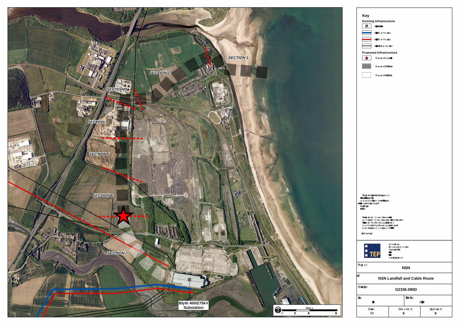
APPENDIX B: PROPOSED SITE LAYOUT
_̂
_̂
SECTION 1
SECTION 2
SECTION 3
SECTION 4
SECTION 5
SECTION 6
SECTION 7
JB
NSN Landfall and Cable Route
JB
14-11-2013 G2336.085D
DH
NSN
This m ap is base d upon O rd nanc e Surve y m ate rial with the pe rm ission of O rd nanc e Surve y on be half of the Controlle r of He r Maje sty’s Statione ry O ffic e © Crown c opyright. Unauthorise d re prod uc tion infringe s Crown c opyright and m ay le ad to prose c ution or c ivil proc e e d ings. Lic e nc e No. 100024241 2013.(c ) Ge tm apping plc .
Ge ne sis Ce ntreBirc hwood Sc ie nc e Park Warrington WA3 7BHTe l 01925 844004Fax 01925 844002e m ail te p@te p.uk.c om
Drawn: Che c ke d : Approve d :
Drawing No:
Title :
Proje c t:
TEP Re f No:Date :
G2336.085D
0 250 500125Me tre s
KeyExisting Infrastructure
Existing 400kV O ve rhe ad Line
Existing 275kV O ve rhe ad Line
This m ap inc lud e s d ata from the following sourc e s:- Natural England - © Natural England [2013], re prod uc e d with the pe rm ission of Natural England , http://www.naturale ngland .org.uk/c opyright/.- English He ritage- National Grid
Existing National Grid Substation
Propose d Conve rtor Station SiteProposed Infrastructure
Existing 132kV or le ss O ve rhe ad Line
Blyth 400/275kVSubstation
Propose d HVDC Cable Route
Propose d HVAC Cable Route
_̂
")

UK - NORWAY ELECTRICITY INTERCONNECTOR (NSN LINK) FLOOD RISK ASSESSMENT
APPENDIX C: CONVERTER STATION LAYOUT

CB
SITE BLOCK PLAN
JB
03-06-2014 G2336.163A
JS
NSN LINK
Genesis CentreBirchwood Science Park Warrington WA3 7BHTel 01925 844004Fax 01925 844002email [email protected]
Drawn: Checked: Approved:
Drawing No:
Title:
Project:
TEP Ref No:Date:
FIGURE 4.1
ISSUE
ACOMMENTS CHK'D APP'DDATE DRAW
03/06/2014 FIRST DRAFT FOR COMMENT JS CB JB
Notes:1. Refer to Figure 4.4 for proposed elevations2. The converter station layout is indicative and included for the purposes of the Outline Planning Application and Environmental Impact Assessment. It is subject to detailed design by the successful Tenderer
Existing Planting
NOT TO SCALE

UK - NORWAY ELECTRICITY INTERCONNECTOR (NSN LINK) FLOOD RISK ASSESSMENT
APPENDIX D: SFRA MAPS

GROWTH POINT AREA/DEVELOPMENT TOWN
South of River Wansbeck & Cambois
FLOOD SOURCES
The map indicates that the low-lying areas adjacent to River Wansbeck and Sleek Burn are at high to intermediate risk from surface water flooding. Significant areas with intermediate to low risk from surface water flooding have been identified in the Cambois growth point. The majority of these areas were occupied by the former Blyth Power Station site.
No incidents of surface water flooding were reported.
It is important to note that the map does not show all sources of flooding, such as fluvial flooding. Please refer to Chapter 2.5 and Appendix B of the SFRA for information on all flood sources.
LIMITATIONS OF DATA
The map shows areas that are susceptible to surface water flooding. When producing these maps, the Environment Agency has used a simplified method that excludes; underground sewerage and drainage systems, smaller over ground drainage systems and buildings. The maps have also been produced using a single rainfall event. Therefore, only provides a general indication of areas which may be more likely to experience surface water flooding.
It should be noted that the maps do not show the susceptibility of individual properties to surface water flooding and represents surface water flooding more accurately in steeper catchments compared to areas with even topography.
BANDINGS
The maps indicates three bandings from “less” to “more” susceptible to surface water flooding. The “more” band identifies areas which a naturally vulnerable to flood first, flood deepest and/or flood for relatively frequent, less extreme events compared to the other bandings.
The Environment Agency advises the LPA to use local data to assess the bands and decide which bands are most appropriate for their purposes, noting that surface water flooding can occur outside of the bands.
FLOOD RISK ASSESSMENT GUIDANCE
Where site specific Flood Risk Assessments (FRAs) are concerned, it should be noted that because of the way the maps have been produced they only provide broad scale indication of surface water flooding. Therefore, the maps are not appropriate to act as the only evidence when making decisions on individual planning applications at any scale without further supporting studies or evidence. LPAs should not use maps to indentify individual properties at risk, and must therefore not be referred to specifically for planning consultations or responses.
Where there is a SFRA exists, LPAs should inform the developer of their SFRA. The developer then must take account of these documents in preparation of the FRA and the LPA must consider the proposal with respect to these documents. However, the EA has requested the LPAs to refer the developers to the EA to obtain the surface water flooding maps. The EA issues these maps in hard copy format on a site-by-site basis as requested by developers.
When preparing FRAs developers should take into account the flood risk from surface water flooding at an early stage. In accordance with Planning Policy Statement 25 (PPS25), management of surface water is critical to mitigate the flood risk to and from the site which could occur as a result of a development. It is recommended that the management of surface water flooding from developments should always aim to reduce the volumes and peak flow rates to be no greater than the rates prior to the proposed development.