Embed Size (px)
Citation preview

CURTAIN FIREDAMPERS
Quality Assurance systemassessed to BS EN ISO 9002
4 hour fire resistance
0100 Series available up to 1.5m x 1.5m in a single module
Infinite sizing capability, withinstated minimum and maximumdimensions
3 alternative casing depths
Standard construction ofgalvanised steel; options withstainless steel blades or stainlesssteel blades and frame
Factory fitted HEVAC/HVCAapproved installation frames
Comprehensive control options
Dry wall frame available
F e a t u r e s
Advanced Air(UK) Limited
A p p r o v a l s
Fire tested to BS 476 Part 8 - FROSI No 6110
Dynamic fire test to Draft ISO 10294/1 LPC TE 81844(0100 Series, to max. test size of 1000 x 1000mm)
LPCB Certificate of Product Conformity - 4 hourresistance integrity
Loss Prevention Council ‘Approved Product’
Accepted by the Department of Architecture and CivicDesign of the Greater London Council
Conformance to DW 142 as appropriate
Lloyds Register of Shipping Certificate No. SVG/F93/094
Underwriters Laboratories Inc. USA
Underwriters Laboratories of Canada
Shock tested to DEF Standard 07-55
Leakage tested by BSRIA - Report No. 3870 Nos. 1&2
Europe, Far East and New Zealand (FRC) Approvals
0100 & 0200 SERIES
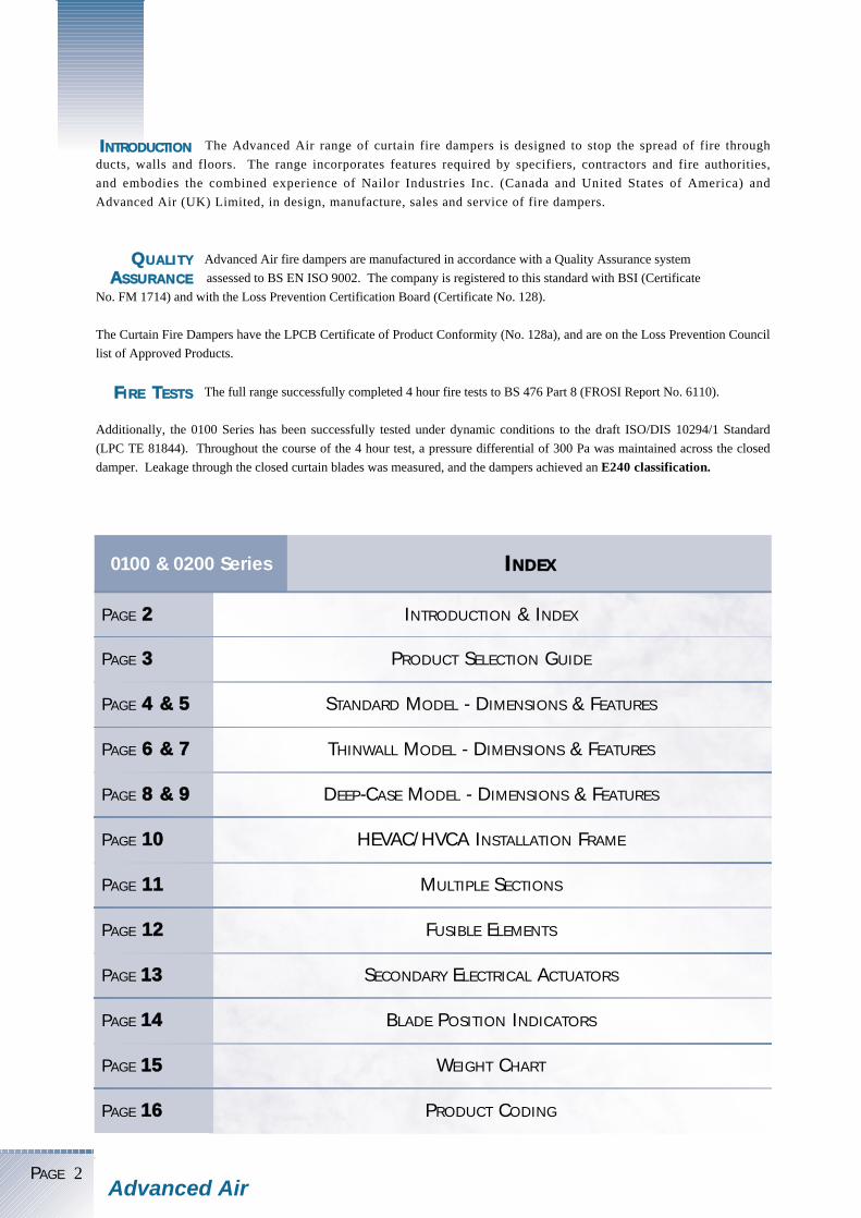
Advanced Air fire dampers are manufactured in accordance with a Quality Assurance system
assessed to BS EN ISO 9002. The company is registered to this standard with BSI (Certificate
No. FM 1714) and with the Loss Prevention Certification Board (Certificate No. 128).
The Curtain Fire Dampers have the LPCB Certificate of Product Conformity (No. 128a), and are on the Loss Prevention Council
list of Approved Products.
QUALITYASSURANCE
The Advanced Air range of curtain fire dampers is designed to stop the spread of fire through
ducts, walls and floors. The range incorporates features required by specifiers, contractors and fire authorities,
and embodies the combined experience of Nailor Industries Inc. (Canada and United States of America) and
Advanced Air (UK) Limited, in design, manufacture, sales and service of fire dampers.
PAGE 2Advanced Air
The full range successfully completed 4 hour fire tests to BS 476 Part 8 (FROSI Report No. 6110).
Additionally, the 0100 Series has been successfully tested under dynamic conditions to the draft ISO/DIS 10294/1 Standard
(LPC TE 81844). Throughout the course of the 4 hour test, a pressure differential of 300 Pa was maintained across the closed
damper. Leakage through the closed curtain blades was measured, and the dampers achieved an E240 classification.
FIRE TESTS
INTRODUCTION & INDEX
PRODUCT SELECTION GUIDE
STANDARD MODEL - DIMENSIONS & FEATURES
THINWALL MODEL - DIMENSIONS & FEATURES
DEEP-CASE MODEL - DIMENSIONS & FEATURES
HEVAC/HVCA INSTALLATION FRAME
MULTIPLE SECTIONS
FUSIBLE ELEMENTS
SECONDARY ELECTRICAL ACTUATORS
BLADE POSITION INDICATORS
WEIGHT CHART
PRODUCT CODING
PAGE 22
PAGE 33
PAGE 44 && 55
PAGE 66 && 77
PAGE 88 && 99
PAGE 1100
PAGE 1111
PAGE 1122
PAGE 1133
PAGE 1144
PAGE 1155
PAGE 1166
INDEX0100 & 0200 Series
INTRODUCTION
PAGE 3Advanced Air
FOR FURTHER TECHNICAL
INFORMATION, SEE PAGES
4 & 5
MAXIMUM SINGLE
SECTION DUCT
SIZE (W X H)
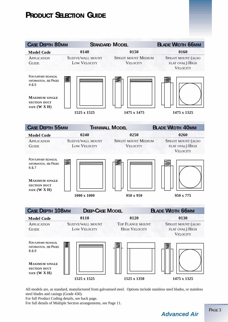
CASE DEPTH 80MM STANDARD MODEL BLADE WIDTH 66MM
Model CodeSLEEVE/WALL MOUNT
LOW VELOCITY
SPIGOT MOUNT MEDIUM
VELOCITY
SPIGOT MOUNT (ALSO
FLAT OVAL) HIGH
VELOCITY
1525 x 1525
0140 0150 0160
1475 x 1475 1475 x 1325
PRODUCT SELECTION GUIDE
All models are, as standard, manufactured from galvanised steel. Options include stainless steel blades, or stainlesssteel blades and casings (Grade 430).For full Product Coding details, see back page.For full details of Multiple Section arrangements, see Page 11.
APPLICATION
GUIDE
FOR FURTHER TECHNICAL
INFORMATION, SEE PAGES
6 & 7
MAXIMUM SINGLE
SECTION DUCT
SIZE (W X H)
CASE DEPTH 55MM THINWALL MODEL BLADE WIDTH 40MM
Model CodeSLEEVE/WALL MOUNT
LOW VELOCITY
SPIGOT MOUNT MEDIUM
VELOCITY
SPIGOT MOUNT (ALSO
FLAT OVAL) HIGH
VELOCITY
1000 x 1000
0240 0250 0260
950 x 950 950 x 775
APPLICATION
GUIDE
FOR FURTHER TECHNICAL
INFORMATION, SEE PAGES
8 & 9
MAXIMUM SINGLE
SECTION DUCT
SIZE (W X H)
CASE DEPTH 108MM DEEP-CASE MODEL BLADE WIDTH 66MM
Model CodeSLEEVE/WALL MOUNT
LOW VELOCITY
TOP FLANGE MOUNT
HIGH VELOCITY
SPIGOT MOUNT (ALSO
FLAT OVAL) HIGH
VELOCITY
1525 x 1525
0110 0120 0130
1525 x 1350 1475 x 1325
APPLICATION
GUIDE

PAGE 4
DUCT WIDTH + 50 mm80
DUCT WIDTH - 4 mm
DU
CT
HE
IGH
T -
4 m
m
DU
CT
HE
IGH
T +
50
mm
5 050
DUCT WIDTH + 110 mm
DU
CT
HE
IGH
T +
11
0 m
m
57
57
9 0
DUCT WIDTH + 60 mm
DU
CT
HE
IGH
T +
60
mm
9 0
DUCT WIDTH + 50 mm80DUCT WIDTH - 4 mm
DU
CT
HE
IGH
T -
4 m
m
'A'
27
5 050
DUCT WIDTH + 110 mmD
UC
T H
EIG
HT
- 4
mm
57
'B'
9 0
DUCT D IA . + 50 mm80
DU
CT
DIA
. -
4 m
m 'C'
27
5 050DUCT D IA + 110mm
DU
CT
DIA
- 4
mm
57
'D'
9 0
DUCT WIDTH + 110 mm
DU
CT
HE
IGH
T -
4m
m
57
'F'
9 0
STANDARD MODEL DIMENS IONAL DATA
Advanced Air
DUCT WIDTH + 50 mm80DUCT WIDTH - 4 mm
DU
CT
HE
IGH
T -
4 m
m 'E'
27
5 050
DUCT WIDTH - 3 mm80
DU
CT
HE
IGH
T -
3 m
m
100 - 300
301 - 525
526 - 700
701 - 925
926 - 1150
1151 - 1325
52 82
77 107
102 132
127 157
152 182
177 207
“A” “B”DUCT HEIGHT
100 - 300
301 - 525
526 - 700
701 - 925
926 - 1000
52 82
77 107
102 132
127 157
152 182
“E” “F”DUCT HEIGHT
100 - 300
301 - 525
526 - 700
701 - 925
926 - 1000
52 82
77 107
102 132
127 157
152 182
“C” “D”DUCT HEIGHT
For full details of Product Coding, see back page
All dimensions in mm
(1000 - 1325 see 0130 Series)
(1000 - 1325 see 0130 Series)
MODELS WITH HEVAC/HVCA INSTALLATION FRAMESBASE MODELS
0140-00 0150-10 0160-10 0160-20 0160-30
0140-00 0140-01
0150-10 0150-11
0160-10 0160-11
0160-20 0160-21
0160-30 0160-31

STANDARD MODEL PRODUCT FEATURES
PAGE 5Advanced Air
Casings: are manufactured from 1.2mm galvanised
mild steel. For 0160-20 Models over 1 metre in
diameter, the casing is manufactured from 1.6mm
galvanised mild steel.
Blades: are specially rollformed from 0.8mm
galvanised mild steel as standard. “Horizontally” and
where specified “Vertically” mounted units, are
complemented with two stainless steel coil type
constant tension springs.
Fusible Link: unless specified otherwise will be
supplied rated at 72oC nominal. (See page 12 for
options).
The 100% galvanised mild steel constructed models
have been successfully corrosion tested by the G.L.C.
Scientific Branch in the U.K. and by U.L. Lab’s in the
U.S.A. to standard U.L. 555. Both tests involve long-
term exposure to highly concentrated salt laden air,
with consequent heavy deposition of materials.
Subsequently, the test units were immediately fired
and operated successfully.
Applicable to 0140 and 0150 Series recommended for Low and Medium velocities
Applicable to 0160 Series recommended for High velocities
PRODUCT SPECIFICATION
CASINGSManufactured from corrosion resistantgalvanised steel as standard.(Grade 430 stainless steel optional).
PULL RINGSTo enable resetting of the damper fromthe non-access side. (Specific sizesonly).
BLADE GUIDE/LOCKING RAMPSGalvanised steel locking ramps ensurepositive blade closure within integralblade guides.
FUSIBLE LINK/RELEASE MECHANISMTypical two-piece fusible link rated at72oC.Alternative temperature rated fusiblelink mechanisms available. (See page 12).
BLADESRollformed single skin interlockinggalvanised high integrity curtain shutter.(Grade 430 stainless steel bladesoptional).
SPRINGSStainless Steel coil tension springsensuring powerful blade closure whenappropriate.
CORROSION TEST
PERFORMANCE DATA
The illustration shows model 0140
00
0.0512.5
0.10 25
0.1537.5
0.2 50
0.2562.5
0.3 INS W.G.75 PASCAL
2.5490
5980
7.51470
101960
12.5m/s2450ft/min
(55% - 78% Free Area)
Duct Velocities
55% Minimum FreeArea
(200 x 200))
78% Maximum Free Area (1000 x 1000
Pres
sure
Dro
p
00
0.1025
0.2 50
0.375
0.4 100
0.5125
0.6 INS W.G.150 PASCAL
5980
101960
152940
203920
25m/s4900ft/min
(100% Free Area)
Duct Velocities
(200 x 200))
(1000 x 1000)
Pres
sure
Dro
p

PAGE 6
DUCT WIDTH + 50 mm55DUCT WIDTH - 4 mm
DU
CT
HE
IGH
T +
50
mm
DU
CT
HE
IGH
T -
4m
m
5 050
DUCT WIDTH + 110 mm
DU
CT
HE
IGH
T +
11
0 m
m
57
57
6 5
DUCT WIDTH + 60 mm
DU
CT
HE
IGH
T +
60
mm
6 5
DUCT WIDTH + 50 mm55DUCT WIDTH - 4 mm
DU
CT
HE
IGH
T -
4 m
m 'A'
27
5 050
DUCT WIDTH + 110 mm
DU
CT
HE
IGH
T -
4 m
m
57
'B'
6 5
DUCT D IA . + 50 mm55
DU
CT
DIA
. -
4 m
m 'C'
27
5 050
DUCT D IA + 110mm
DU
CT
DIA
- 4
mm
57
'D'
6 5
DUCT WIDTH + 110 mm
DU
CT
HE
IGH
T -
4M
M
57
'F'
6 5
THINWALL MODEL DIMENS IONAL DATA
Advanced Air
DUCT WIDTH - 4 mm
DU
CT
HE
IGH
T -
4 m
m
DUCT WIDTH + 50 mm5550
'E'
27
5 0
DUCT WIDTH - 3 mm55
DU
CT
HE
IGH
T -
3 m
m
100 - 150151 - 275276 - 375376 - 500501 - 625626 - 725726 - 775
5277102127152177202
82107132157182207232
“A” “B”DUCT HEIGHT
100 - 150151 - 275276 - 375376 - 500501 - 625626 - 725726 - 775
5277102127152177202
82107132157182207232
“C” “D”DUCT HEIGHT
100 - 150151 - 275276 - 375376 - 500501 - 625626 - 725726 - 775
5277102127152177202
82107132157182207232
“E” “F”DUCT HEIGHT
All dimensions in mm
For full details of Product Coding, see back page
MODELS WITH HEVAC/HVCA INSTALLATION FRAMESBASE MODELS
0240-00 0250-10 0260-10 0260-20 0260-30
0240-00 0240-01
0250-10 0250-11
0260-10 0260-11
0260-20 0260-21
0260-30 0260-31

TH INWALL MODEL PRODUCT FEATURES
PAGE 7Advanced Air
Casings: are manufactured from 1.2mm galvanised
mild steel.
Blades: are specially rollformed from 0.8mm
galvanised mild steel as standard. “Horizontally” and
where specified “Vertically” mounted units, are
complemented with two stainless steel coil type
constant tension springs.
Fusible Link: unless specified otherwise will be
supplied rated at 72oC nominal.
(See page 12 for options).
The 100% galvanised mild steel constructed models
have been successfully corrosion tested by the G.L.C.
Scientific Branch in the U.K. and by U.L. Lab’s in the
U.S.A. to standard U.L. 555. Both tests involve long-
term exposure to highly concentrated salt laden air,
with consequent heavy deposition of materials.
Subsequently, the test units were immediately fired
and operated successfully.
PRODUCT SPECIFICATION
CASINGSManufactured from corrosion resistantgalvanised steel as standard.(Grade 430 stainless steel optional).
PULL RINGSTo enable resetting of the damper fromthe non-access side. (Specific sizesonly).
BLADE GUIDE/LOCKING RAMPSGalvanised steel locking ramps ensurepositive blade closure within integralblade guides.
FUSIBLE LINK/RELEASE MECHANISMTypical two-piece fusible link rated at72oC.Alternative temperature rated fusiblelink mechanisms available. (See page 12).
BLADESRollformed single skin interlockinggalvanised high integrity curtain shutter.(Grade 430 stainless steel bladesoptional).
SPRINGSStainless Steel coil tension springsensuring powerful blade closure whenappropriate.
CORROSION TEST
The illustration shows model 0240
Applicable to 0240 and 0250 Series recommended for Low and Medium velocities
Applicable to 0260 Series recommended for High velocities
PERFORMANCE DATA
00
0.0512.5
0.10 25
0.1537.5
0.2 50
0.2562.5
0.3 INS W.G.75 PASCAL
2.5490
5980
7.51470
101960
12.5m/s2450ft/min
(55% - 78% Free Area)
Duct Velocities
55% Minimum FreeArea
(200 x 200))
78% Maximum Free Area (1000 x 1000
Pres
sure
Dro
p
00
0.1025
0.2 50
0.375
0.4 100
0.5125
0.6 INS W.G.150 PASCAL
5980
101960
152940
203920
25m/s4900ft/min
(100% Free Area)
Duct Velocities
(200 x 200))
(1000 x 1000)
Pres
sure
Dro
p

PAGE 8
DUCT WIDTH - 6mm108 5050
DU
CT
HE
IGH
T -
4m
m
27
'A'
DUCT WIDTH - 4mmDUCT WIDTH + 50mm
108
DU
CT
HE
IGH
T -
4m
m
27
'B'
DUCT WIDTH + 110mm
DU
CT
HE
IGH
T -
4m
m
57
'C'
1 22
108 DUCT D IA . + 50mm
DU
CT
DIA
. -
4m
m
'D'5 0 50
27
DUCT D IA+ 110mm
DU
CT
DIA
- 4
mm
57
'E'
1 22
DUCT WIDTH + 110 mm
DU
CT
HE
IGH
T -
4m
m
57
'G'
1 22
DEEP CASE MODEL DIMENS IONAL DATA
Advanced Air
DUCT WIDTH + 50 mm108DUCT WIDTH - 4 mm
DU
CT
HE
IGH
T -
4 m
m 'F'
27
5 050
DUCT WIDTH - 6mm108
DU
CT
HE
IGH
T -
6m
m
All dimensions in mm
1001 - 11501151 - 1325
152177
182207
“F” “G”DUCT HEIGHT
1001 - 11501151 - 1325
152177
182207
“D” “E”DUCT HEIGHT
100 - 300301 - 525526 - 700701 - 925926 - 11501151 - 1325
5277102127152177
82107132157182207
“B” “C”DUCT HEIGHT
100 - 300301 - 525526 - 700701 - 925926 - 11501151 - 1350
5277102127152177
“A”DUCT HEIGHT
For full details of Product Coding, see back page
MODELS WITH HEVAC/HVCA INSTALLATION FRAMES
NOT AVAILABLE FOR THIS MODEL
NOT AVAILABLE FOR THIS MODEL
BASE MODELS
0110-00 0120-00 0130-00 0130-20 0130-30
0110-00
0120-00
0130-00 0130-01
0130-20 0130-21
0130-30 0130-31
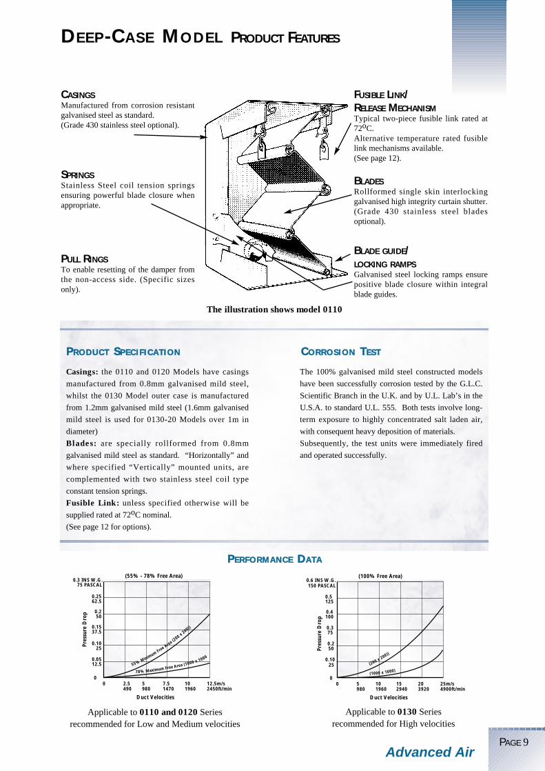
DEEP -CASE MODEL PRODUCT FEATURES
PAGE 9Advanced Air
Casings: the 0110 and 0120 Models have casings
manufactured from 0.8mm galvanised mild steel,
whilst the 0130 Model outer case is manufactured
from 1.2mm galvanised mild steel (1.6mm galvanised
mild steel is used for 0130-20 Models over 1m in
diameter)
Blades: are specially rollformed from 0.8mm
galvanised mild steel as standard. “Horizontally” and
where specified “Vertically” mounted units, are
complemented with two stainless steel coil type
constant tension springs.
Fusible Link: unless specified otherwise will be
supplied rated at 72oC nominal.
(See page 12 for options).
The 100% galvanised mild steel constructed models
have been successfully corrosion tested by the G.L.C.
Scientific Branch in the U.K. and by U.L. Lab’s in the
U.S.A. to standard U.L. 555. Both tests involve long-
term exposure to highly concentrated salt laden air,
with consequent heavy deposition of materials.
Subsequently, the test units were immediately fired
and operated successfully.
PRODUCT SPECIFICATION
CASINGSManufactured from corrosion resistantgalvanised steel as standard.(Grade 430 stainless steel optional).
PULL RINGSTo enable resetting of the damper fromthe non-access side. (Specific sizesonly).
BLADE GUIDE/LOCKING RAMPSGalvanised steel locking ramps ensurepositive blade closure within integralblade guides.
FUSIBLE LINK/RELEASE MECHANISMTypical two-piece fusible link rated at72oC.Alternative temperature rated fusiblelink mechanisms available. (See page 12).
BLADESRollformed single skin interlockinggalvanised high integrity curtain shutter.(Grade 430 stainless steel bladesoptional).
SPRINGSStainless Steel coil tension springsensuring powerful blade closure whenappropriate.
CORROSION TEST
The illustration shows model 0110
Applicable to 0110 and 0120 Series recommended for Low and Medium velocities
Applicable to 0130 Series recommended for High velocities
PERFORMANCE DATA
00
0.0512.5
0.10 25
0.1537.5
0.2 50
0.2562.5
0.3 INS W.G.75 PASCAL
2.5490
5980
7.51470
101960
12.5m/s2450ft/min
(55% - 78% Free Area)
Duct Velocities
55% Minimum FreeArea
(200 x 200))
78% Maximum Free Area (1000 x 1000
Pres
sure
Dro
p
00
0.1025
0.2 50
0.375
0.4 100
0.5125
0.6 INS W.G.150 PASCAL
5980
101960
152940
203920
25m/s4900ft/min
(100% Free Area)
Duct Velocities
(200 x 200))
(1000 x 1000)
Pres
sure
Dro
p

PAGE 10
HEVAC/HVCA I NSTAL LAT ION FRAME
ADDITIONAL NOTE
(CONFORMING TO SPECIFICATION NO HVC 6-5-83)
(a) in brickwork or blockwork walls and floors, the tabs shall be bent out and solidly built into mortar jointsbetween the brickwork or blockwork;(b) in the case of reinforced concrete walls and floors, the tabs shall be bent out and tied with wire to thereinforcing bars which will be deliberately left protruding into the opening and then the gap between theinstallation frame and the builders work backfilled with mortar or concrete on both sides of the flange(c) it is recommended that the fixing tabs are welded, bolted or wired back to supporting steelwork or anequivalent rigid structural member, to ensure that the installation strength is maximised.
Advanced Air (UK) Ltd recommend the above as the standard method for installation. However, the District Surveyor, Fire
Officer, and/or Specifying Authority as appropriate, may approve other methods of installation
Advanced Air
The installation frame is factory fitted to its respective fire damper and the assembly is delivered to site as one unit. Itobviates the need for sleeve and angle fitting and allows expansion of the fire damper in a fire condition within the frame, sothat the integrity of the fire wall or floor is not affected.
Flange with fixingtabs ensuresmaximum captivestrength whenfitted to builderswork.
Corner joints fittedwith all aluminium
rivets ensuresunimpeded
expansion offrame.
Corner mitresallow for frameexpansion. Firedamper is locatedcentrally by foldedcorner spacers.
The frame shall be installed centrally in the
th i cknes s o f a b r i ckwork o r conc re t e
surrounding wall or floor, or in the case of thick
walls or floors, so that the centre line of the
frame is at least 50mm away from the nearest
face of the wall or floor in which the assembly
is mounted.
Adjacent frame assemblies must be separated by
builders work of minimum thickness of 225mm
(between installation frame upstand flanges)
unless approval has been previously obtained
from the appropriate authority.
MAXIMUM DUCT DIMENSIONS: 2000 X 1475MM
MATERIAL: GALVANISED STEEL
225mm
50mm

PAGE 11
��
��
���
�����
Where multiple arrangements of Fire Dampers are
required to be fitted, the installer should submit his
proposed arrangement to the relevant local
authority or fire officer responsible for installation.
Closure strips of 1.2mm galvanised sheet steel in
“U” formed sections are supplied undrilled with all
Advanced Air Damper multiple assemblies of the
spigotted type, for positioning as shown to form
centre mullions 50mm x 50mm.
0110 & 0140
0120
0130 - 20
0130 - 30
0160 -10 & - 30
0160 - 20
3050 x 3050mm
3050 x 2875mm
2850mm dia.
3000 x 2850mm
3000 x 2850mm
1000mm dia.
Units are available up to:
Units are available up to:
MULT IP L E SECT IONS
����
�� ����Advanced Air Series 0100 and 0200 curtain
fire dampers have been successfully tested
and approved for use in 4 hour constructions.
When required by a District Surveyor, Fire
Officer, or specifying authority, two standard
fire dampers may be f i t ted back to back.
This arrangement is available for all square,
rectangular, round and oval spigotted models.
F i t t ing i s by inser t ing one sp igot wi th in
another, creating a male/female connection
(see i l lustrat ion). Where HEVAC/HVCA
installation frames are required, one such
frame must be fitted to each damper in the
assembly.
Advanced Air
MULTIPLE HORIZONTAL
ARRANGEMENT
DOUBLE UNITS
MULTIPLE VERTICALARRANGEMENT
0110 & 0140
0120
0130 - 20
0130 - 30
0160 -10 & - 30
0160 - 20
2590 x 1525mm
2590 x 1370mm
1350mm dia.
2550 x 1350mm
2550 x 1325mm
1000mm dia.

Please note that certain combinations of link, micro-switch, VPI, etc. may not be available on smaller units.
Please contact the Sales Office for full details.
This Flat-Bar Link is the standard link used, and
is held in position by removable chain links
Allows the Fire Damper to be tested quickly and
sa f e ly . The dampe r c an be mechan i ca l l y
released and reloaded with one hand on small
units from indicated side of the duct.
(The E.M.L. must be specifically ordered, as it is
an option).
A dual response fusible l ink which reacts
(melts) when subjected to either local heat or
an electrical impulse of low power and short
duration. The standard temperature rating is
74oC. The low power requirement of the
E.T.L. means that it can be released with an
e l ec t r i c a l impu l se (50 mi l l i s econds o f
between 6 volt and 30 volt AC or DC with a
minimum current of 0 .2 amperes) f rom a
suitable smoke detector or other source.
FLAT BAR LINK
EASY MAINTENANCE LINK - E.M.L.
ELECTRO-THERMAL LINK - E.T.L.
PAGE 12Advanced Air
FUS IBLE ELEMENTS
MINIMUM DAMPER SIZE
oC72o (Standard)
68o (Optional)
120o (Optional)
182o (Optional)
58o (Optional)
100o (Optional)
140o (Optional)
72 oC
72 oC
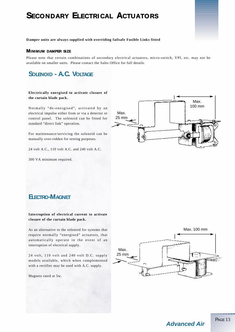
SECONDARY ELECTR ICAL ACTUATORS
PAGE 13Advanced Air
Please note that certain combinations of secondary electrical actuators, micro-switch, VPI, etc. may not be
available on smaller units. Please contact the Sales Office for full details.
Damper units are always supplied with overriding failsafe Fusible Links fitted
Electrically energised to activate closure ofthe curtain blade pack.
Norma l ly “de - ene rg i s ed” , a c t i va t ed by an
electrical impulse either from or via a detector or
control panel. The solenoid can be fitted for
standard “direct link” operation.
For maintenance/servicing the solenoid can be
manually over-ridden for testing purposes.
24 volt A.C., 110 volt A.C. and 240 volt A.C.
300 VA minimum required.
Interruption of electrical current to activateclosure of the curtain blade pack.
As an alternative to the solenoid for systems that
require normally “energised” actuators , that
au toma t i ca l l y ope ra t e i n t he even t o f an
interruption of electrical supply.
24 vo l t , 110 vo l t and 240 vo l t D .C. supp ly
models available, which when complemented
with a rectifier may be used with A.C. supply.
Magnets rated at 5w.
SOLENOID - A.C. VOLTAGE
ELECTRO-MAGNET
MINIMUM DAMPER SIZE
Max.25 mm
Max.100 mm
Max.25 mm
Max. 100 mm

Please note that certain combinations of blade position indicator, link, etc. may not be available on smaller units.
Please contact the Sales Office for full details.
To provide remote indication of whether the Blade Pack is open or closed.
The micro-switch can also be connected to any warning device controls circuit.
The electrical circuit is completed or broken when the lowest blade operates the arm of the micro-switch.
2 POLE - 1 NORMALLY CLOSED
+ 1 NORMALLY OPEN
SNAP ACTION
SUITABLE FOR UP TO 240V, 3A
To provide local indication of whether the blade pack is open or closed.
ELECTRICAL MICRO-SWITCH
VISUAL POSITION INDICATOR
PAGE 14Advanced Air
BLADE POS I T ION IND ICATORS
MINIMUM DAMPER SIZE
(PROVIDING REMOTE INDICATION)
(PROVIDING LOCAL INDICATION)
CURTAIN BLADE OPEN POSITION CURTAIN BLADE CLOSED POSITION
This indicator is normally fitted within the vertical face of the
case adjacent to the bottom blade when in the closed position

ADVANCED AIR - FIRE DAMPERS - NETT WEIGHTS
All weights are approximate and in Kilograms
WEIGHT CHART
PAGE 15Advanced Air
150 200 300 400 450 600 750 900 1050 1200 1500WIDTH (MM)
HEI
GH
T(M
M)
1
2
3
4
4
6
8
9
11
13
2003004506007509001050120013501500
2
2
3
4
5
6
8
9
11
13
2
3
4
6
6
7
9
10
12
14
3
4
4
7
8
8
10
12
14
16
3
4
5
7
8
8
10
12
14
16
5
5
7
8
9
10
12
13
16
17
6
7
7
9
10
11
12
14
17
19
6
7
8
10
11
12
14
15
17
20
8
9
10
12
12
14
16
18
20
24
9
10
12
13
14
15
18
23
26
30
10
12
15
17
19
21
25
28
31
36
GROUPSTRUCTURE
COMPANYDEVELOPMENT
ASSUREDQUALITY
CUSTOMERSERVICE
Advanced Air (UK) Limited is a member of the Nailor Industries International Group. The Group started operations in Toronto in 1971, founded by the current President and Chief
Executive Officer, Michael Nailor. Today there are factories in Toronto and Calgary in Canada, in Houston andFlorida in the USA, with Advanced Air (UK) Ltd. in Bury St Edmunds. The Group’s Research and DevelopmentLaboratory is located in Houston.
The Group manufactures a full range of dampers and air distribution products, including fire, smoke and controldampers, fire rated ceiling products, grilles, diffusers and VAV terminal units.
Formed in 1975, Advanced Air (UK) Ltd. relocated to Bury St Edmunds in 1980, where the company now occupies three manufacturing units.
These factories produce fire, smoke and control dampers for the UK and export markets. With agents anddistributors throughout Europe and the rest of the world, Advanced Air operates in a continually developinginternational market.
The company has always placed great emphasis on quality of production and design, and was among the first HVAC companies in the UK to be registered to BS 5750. Advanced Air’s
quality assurance system is now assessed to BS EN ISO 9002, through both BSI and the Loss PreventionCertification Board. The company’s fire and smoke dampers are included in the Loss Prevention Council’s list ofApproved Products.
Advanced Air has always been a customer led company, responding to the needs and demands of specifiers, designers and contractors. This has led to continuous improvement in
product design and in manufacturing technology. The company’s customer service function is seen as a key factorin Advanced Air’s success.
Ultimately, the customer requires the best possible products at competitive prices. Advanced Air meets thisdemand for value for money by focusing on simplicity in design, fitness for purpose, and high quality/low costproduction.
The company also keeps in touch with the wider issues affecting the HVAC industry, developing solutions to theproblems raised in such areas as lower energy usage, tighter fire safety regulations, indoor air quality, and therequirements of new European and worldwide standards.
1. The above nett weights are relevant to Models 0110 and 0140.2. For Models 0120 and 0150, a multiplier of 1.5 on the above weights should be used.3. For Models 0130 and 0160, a multiplier of 2 should be employed and where in addition an HEVAC/HVCA installationframe is included, an alternative multiplier of 3 should be utilised.4. Where Model 0200 Series are employed, a multiplier against the relevant pattern of 1.2 in addition should be used.

Advanced Air(UK) Limited
PO Box 153, Burrell Way, Thetford, Norfolk IP24 3WB, England Tel: 01842 753624 Fax: 01842 762032
The information contained in this publication is correct at the time of printing. Continuous product development means that from timeto time product specifications and other information will change. The company therefore reserves the right to modify or withdraw any
of the products described without prior notice
DES
IGN
EDA
ND
PRO
DU
CED
BY
TGL
TE
L: 0
1787
379
955
◆ SERIES 1000 - UNIVERSAL VOLUME CONTROL DAMPERS◆ SERIES 1200 - FIRE/SMOKE/CONTROL DAMPERS◆ SERIES 1400 - SLIMLINE BALANCE AND CONTROL DAMPERS◆ SERIES 2300 - LEAKAGE RATED FIRE/SMOKE DAMPERS◆ SERIES 2400 - INSULATED FIRE/SMOKE DAMPERS◆ SERIES 4000 - FIRE RATED DIFFUSER ASSEMBLIES◆ SERIES 0800 - ACCESS DOORS◆ SMOKE MANAGEMENT SYSTEMS
TYPICAL ORDER DETAIL
ASSOCIATED PRODUCTS
MOUNTING TYPE
0. BASE1. HEVAC/
HVCA FRAME
2. ONE MICRO SWITCH
3. HEVAC FRAME & MICRO SWITCH
4. TWO MICRO SWITCHES
5. TWO MICRO SWITCHES& FRAME
0. BASE1. HEVAC/
HVCA FRAME
2. ONE MICRO SWITCH
3. HEVAC FRAME & ONE MICRO SWITCH
4. TWO MICRO SWITCHES
5. TWO MICRO SWITCHES& FRAME
MATERIAL
0. GALV1. GRADE 430
S/S BLADES GALV CASE
2. GRADE 430S/S BLADES & CASING
0. GALV1. GRADE 430
S/S BLADES GALV CASE
2. GRADE 430S/S BLADES & CASING
PRODUCTGROUP
01
02THINWALL
FACE FITTING
0. BASE 1. RECTAN.
GULARSPIGOT
2. CIRCULARSPIGOT
3. FLAT OVAL SPIGOT
0. BASE 1. RECT
SPIGOT2. CIRCULAR
SPIGOT3. FLAT
OVAL SPIGOT
SECONDARYSIGNAL
ACTUATION0. BASE 1. ETL 5. SOLENOID6. MAGNET9. EML
0. BASE 1. ETL5. SOLENOID 6. MAGNET9. EML
MODEL
1. SLEEVE2. TOP
FLANGEMOUNT
3. SPIGOT4. SLEEVE5. RECT.
SPIGOT(BLADES
PARTLY IN
AIRSTREAM)6. SPIGOT
(BLADES
OUT OF
AIRSTREAM)
4. SLEEVE5. RECT.
SPIGOT(BLADES
PARTLY IN
AIRSTREAM)6. SPIGOT
(BLADES
OUT OF
AIRSTREAM)
PRODUCT CODING
0169-11
SIZE (W X H)MM QUANTITY FEATURES
300 X 300 10100% GALV. STEEL BLADES AND
CASING. HEVAC/HVCAINSTALLATION FRAMES E.M.L.
Other fully tested and approved product groups available include:
MODEL REF
MEMBER
Note: 430 Gradestainless steel is notsuitable for hostileor corrosiveenvironments.