Embed Size (px)
Citation preview
Fire safety products | 1 / 7
Systemair Fire DampersFire resistance class EI60S; EI90S and EI120S
DescriptionAs standard, all fire dampers are designed and certified to comply with EI-S performance attributes. PKIR and PKIS fire dampers are intended to be embedded into fire partition walls or ceilings. Installation of these units is described in the Installation, Operation and Maintenance manual for rectangular and circular fire dampers. As standard, all dampers can be supplied with a manual actuator, optional accessories, e.g. microswitches, electromagnets, or a servo-driven actuator and communication control units.
Fire Dampers With a Manual ActuatorFire damper automatically sets itself to closed position if the thermal fuse link gets ruptured or a signal is given to the electromagnet to release the damper blade from an open to closed position. After the closure, the damper blade is mechanically secured in the closed position and can only be opened manually. The fast blow fuse releases the link mechanism as soon as the air temperature in the duct system reaches 72 °C and the damper blade closes within 10 seconds..
Servo-driven Fire DampersFire dampers can be equipped with a servo that closes the damper blade on demand of the Building Management System or based on a signal received from the thermoelectric fuse. Servo fitted fire dampers are standardly equipped with an electrothermal fuse which, when having reached or exce eded the ambient temperature of 72°C with a tolerance of ±1.5°C, activates the servo and closes the damper blade within 20 seconds.
Ordering codes
PK-I-R-EI-
Fire resistance class
Dimensions
Operation type
60S, 90S and 120S
ZVDV1 to DV9 - T - W
øD
Connection types PMounting flanges
PK-I-S-EI-
Fire resistance class
Dimensions
Operation type
90S and 120S
ZVDV1 to DV9 - T - W
L × H
Ordering Codes for Circular FD:
Ordering Codes for Rectangular FD:
NOTES: E = Casing integrityI = Thermal insulationS = Smoke leakage
1396 - CPD - 0061 1396 - CPD - 0062
2 / 7 | Fire safety products
Installation, Operation and MaintenanceFire dampers must be installed, operated and maintained according to the Installation, Operation and Maintenance manual
Operating ConditionsDampers equipped with manual actuating mechanism and thermal fuse with a low melting alloy may be operated in a workplace where the operating temperatures fall in the range between -10 to 65°C. A damper equipped with a manual actuating mechanism and an electromagnet may be operated in a workplace where the temperature falls in the range of -10 to 40°C. Dampers equipped with a servo and a thermal fuse may be operated in a workplace with the ambient operating temperatures within the range between -10 to 65°C.The active fire-proof sealing must not be exposed to direct contact with water. The maximum air flow speed is 12 m/s with clean air without mechanic or chemical contamination with uniform flow, without condensation, ice coating and ice. The maximum allowable pressure difference in front and behind the closed blade is 1200 Pa. The device is not actuated until the ambient temperature reaches 65°C. In case of need of adjustment for higher temperatures in the working place it is advisable to consult such demands with the producer and indicate them in the purchase order accordingly. In terms of their construction, the dampers are designed for use with a horizontal, vertical or angled blade axis.
Transportation, Storage and Operating conditionsIt is necessary to transport the dampers by such means of transport that provide a cover and secured on pallets. When handling the dampers during transportation, the dampers must be protected against damage and weather conditions. The damper blades must be transported in the “CLOSE” position. It is recommended to store these products in a closed, dry, area where the temperature falls within the range of -10°C to +50°C. The temperature during storage, transportation and operation must not exceed 65°C!
Material used and disposalThe product contains steel, zinc, calcium-silicate board, graphite fire-proof laminate, polyurethane foam and ethylene-propylene dry rubber. These are processed in compliance with local regulations. The product does not
contain any dangerous materials, with the exception of the solder’s miligram quantity that contains Pb.
WarrantyThe manufacturer provides a 24-month warranty period starting on the date of expedition.
AppendixAny demands regarding deviations from the above mentioned technical specifications and conditions shall be discussed with the manufacturer. The manufacturer reserves the right to perform any modifications of the product without prior notice, provided that such changes have no effect on the quality and performance of the product. The most recent state of our products is available at www.imos-systemair.sk
Damper Codes and TypesZV; Basic model with manual crank and an actuating mechanism with spring return release driven by a fusible thermal link set to 72 °C.
DV1; ZV + closed position indication with a 24 V contact switch
DV1-2; ZV + open and closed indication with 24 V contact switches
DV2; ZV + closed position indication with a contact switch 230 V
DV2-2; ZV + open and closed indication with 230 V contact switches
DV3; ZV + 24 V AC electromagnetic re lease mechanism (release takes place when the electromagnet is activated)
DV4; ZV + 230 V AC electromagnetic release mechanism (release takes place when the electromagnet is activated)
DV5; ZV + 24 V AC electromagnetic release mechanism (release takes place when the electromagnet is activated) plus 24 V switch indicating the damper’s closed position
DV5-2; ZV + 24 V AC electromagnetic release mechanism (release takes place when the electromagnet is activated) plus 24 V switches indicating the damper’s closed and open position
DV6; ZV + 230 V AC electromagnetic release mechanism (release takes place when the electromagnet is activated) plus 230 V switch indicating the damper’s
Fire safety products | 3 / 7
closed position
DV6-2; ZV + 230 V AC electromagnetic release mechanism (release takes place when the electromagnet is activated) plus 230 V switches indicating the damper’s closed and open position
DV3B to DV6B-2; the same as DV3 to DV6-2 with electromagnet in interruption connection (release takes place by the interruption of the current in the electromagnet)
Servo-operated Fire Dampers:
DV7; spring return servo-operated fire dampers (230 V AC) without electro-thermal fuse, with auxiliary switches
DV7-T; spring return servo-operated fire dampers (230 V AC) with electro-thermal fuse and auxiliary switches
DV9; spring return servo-operated fire dampers (24 V) without electro-thermal fuse with auxiliary switches
DV9-T; spring return servo-operated fire dampers (24 V) with electro-thermal fuse and auxiliary switches
DV9-ST; spring return servo-operated fire dampers (24 V) without electro-thermal fuse, with auxiliary switches and Belimo BKN230-24 supply and communication unit.
DV9-T-ST; spring return servo-operated fire dampers (24 V) with electro-thermal fuse, auxiliary switches and Belimo BKN230-24 supply and communication unit
DV9-W; spring return servo-operated fire dampers (24 V) with auxiliary switches and cables for the Belimo BKN230-24 supply and communication unit
DV9-T-W; spring return servo-operated fire dampers (24 V) complete with electro-thermal fuse, auxiliary switches and with the cables for the Belimo BKN230-24 supply and communication unit
Connection TypeP – by mounting flanges
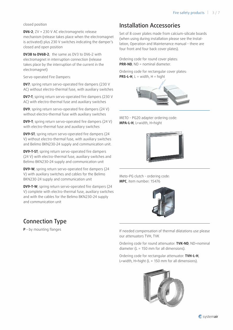
Installation AccessoriesSet of 8 cover plates made from calcium-silicate boards (when using during installation please see the Instal-lation, Operation and Maintenance manual - there are four front and four back cover plates).
Ordering code for round cover plates: PRR-ND, ND = nominal diameter.
Ordering code for rectangular cover plates: PRS-L-H, L = width, H = hight
METO - PG20 adapter ordering code: MPA-L-H, L=width, H=hight
Meto-PG clutch - ordering code: MPC, item number: 15476
If needed compensation of thermal dilatations use please our attenuators TVH, TVK
Ordering code for round attenuator: TVK-ND, ND=nominal diameter (L = 150 mm for all dimensions).
Ordering code for rectangular attenuator: TVH-L-H, L=width, H=hight (L = 150 mm for all dimensions).
4 / 7 | Fire safety products
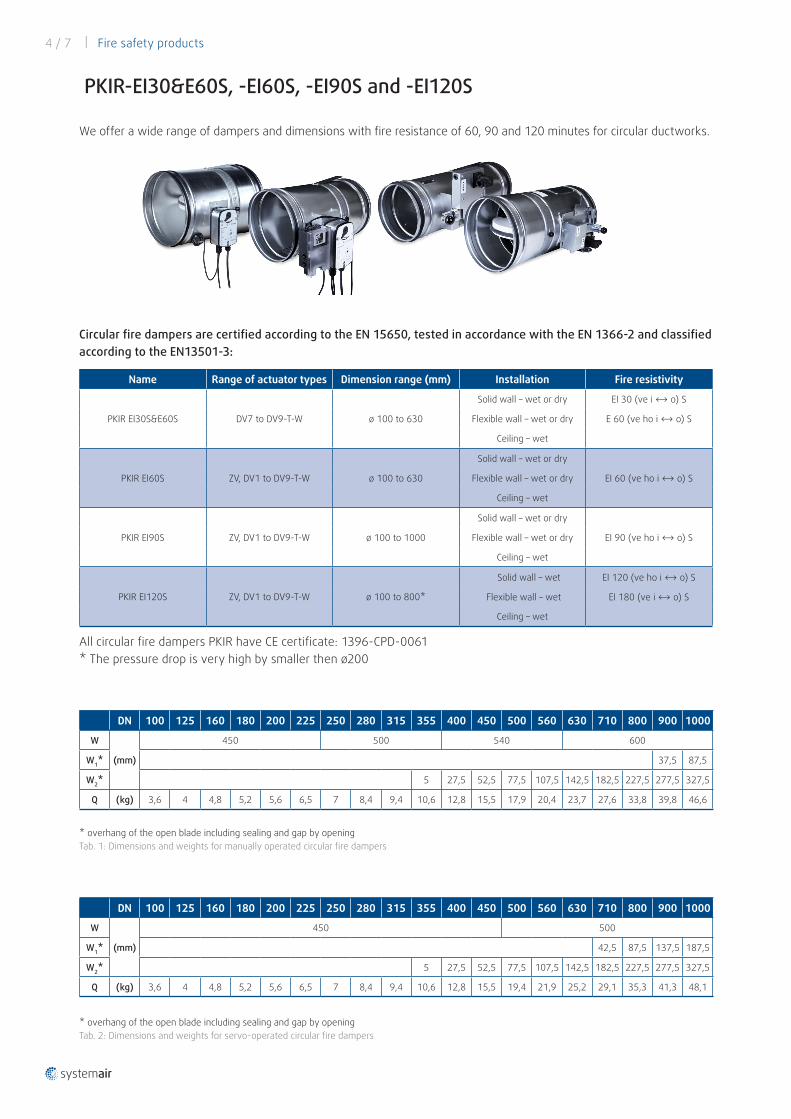
PKIR-EI30&E60S, -EI60S, -EI90S and -EI120S
We offer a wide range of dampers and dimensions with fire resistance of 60, 90 and 120 minutes for circular ductworks.
Circular fire dampers are certified according to the EN 15650, tested in accordance with the EN 1366-2 and classified according to the EN13501-3:
Name Range of actuator types Dimension range (mm) Installation Fire resistivity
PKIR EI30S&E60S DV7 to DV9-T-W ø 100 to 630
Solid wall – wet or dry EI 30 (ve i ↔ o) S
Flexible wall – wet or dry E 60 (ve ho i ↔ o) S
Ceiling – wet
PKIR EI60S ZV, DV1 to DV9-T-W ø 100 to 630
Solid wall – wet or dry
EI 60 (ve ho i ↔ o) SFlexible wall – wet or dry
Ceiling – wet
PKIR EI90S ZV, DV1 to DV9-T-W ø 100 to 1000
Solid wall – wet or dry
EI 90 (ve ho i ↔ o) SFlexible wall – wet or dry
Ceiling – wet
PKIR EI120S ZV, DV1 to DV9-T-W ø 100 to 800*
Solid wall – wet EI 120 (ve ho i ↔ o) S
Flexible wall – wet EI 180 (ve i ↔ o) S
Ceiling – wet
All circular fire dampers PKIR have CE certificate: 1396-CPD-0061 * The pressure drop is very high by smaller then ø200
DN 100 125 160 180 200 225 250 280 315 355 400 450 500 560 630 710 800 900 1000
W
(mm)
450 500 540 600
W1* 37,5 87,5
W2* 5 27,5 52,5 77,5 107,5 142,5 182,5 227,5 277,5 327,5
Q (kg) 3,6 4 4,8 5,2 5,6 6,5 7 8,4 9,4 10,6 12,8 15,5 17,9 20,4 23,7 27,6 33,8 39,8 46,6
DN 100 125 160 180 200 225 250 280 315 355 400 450 500 560 630 710 800 900 1000
W
(mm)
450 500
W1* 42,5 87,5 137,5 187,5
W2* 5 27,5 52,5 77,5 107,5 142,5 182,5 227,5 277,5 327,5
Q (kg) 3,6 4 4,8 5,2 5,6 6,5 7 8,4 9,4 10,6 12,8 15,5 19,4 21,9 25,2 29,1 35,3 41,3 48,1
* overhang of the open blade including sealing and gap by openingTab. 1: Dimensions and weights for manually operated circular fire dampers
* overhang of the open blade including sealing and gap by openingTab. 2: Dimensions and weights for servo-operated circular fire dampers
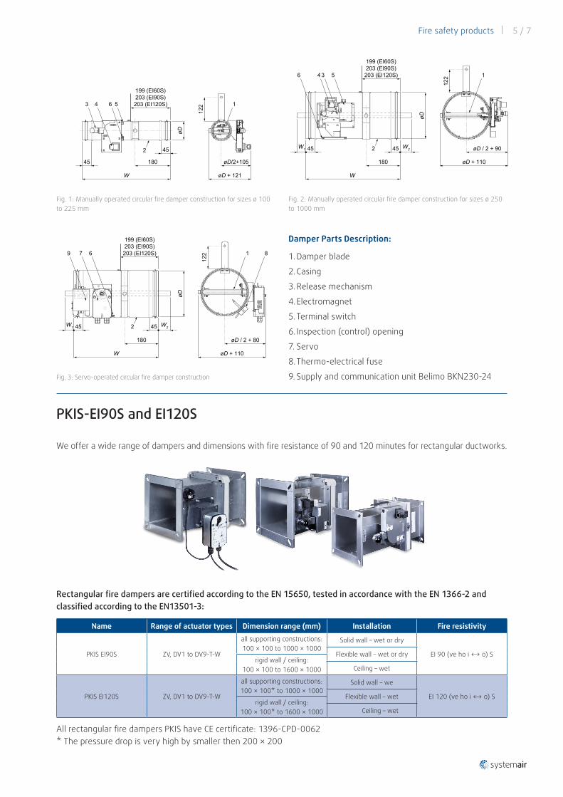
Fire safety products | 5 / 7
W
45
6
2
øD
3 4
øD + 121
øD/2+105
5
122
180
199 (EI60S)203 (EI90S)203 (EI120S)
45
1
W
45 45
øD
4 3 56
W2W1
øD + 110
øD / 2 + 90
180
199 (EI60S)203 (EI90S)203 (EI120S)
2
122 1
W2W1
W
45 45
øD
øD / 2 + 80
øD + 110
7 6
122
180
199 (EI60S)203 (EI90S)203 (EI120S)9
2
1 8
Fig. 1: Manually operated circular fire damper construction for sizes ø 100 to 225 mm
Fig. 2: Manually operated circular fire damper construction for sizes ø 250 to 1000 mm
Fig. 3: Servo-operated circular fire damper construction
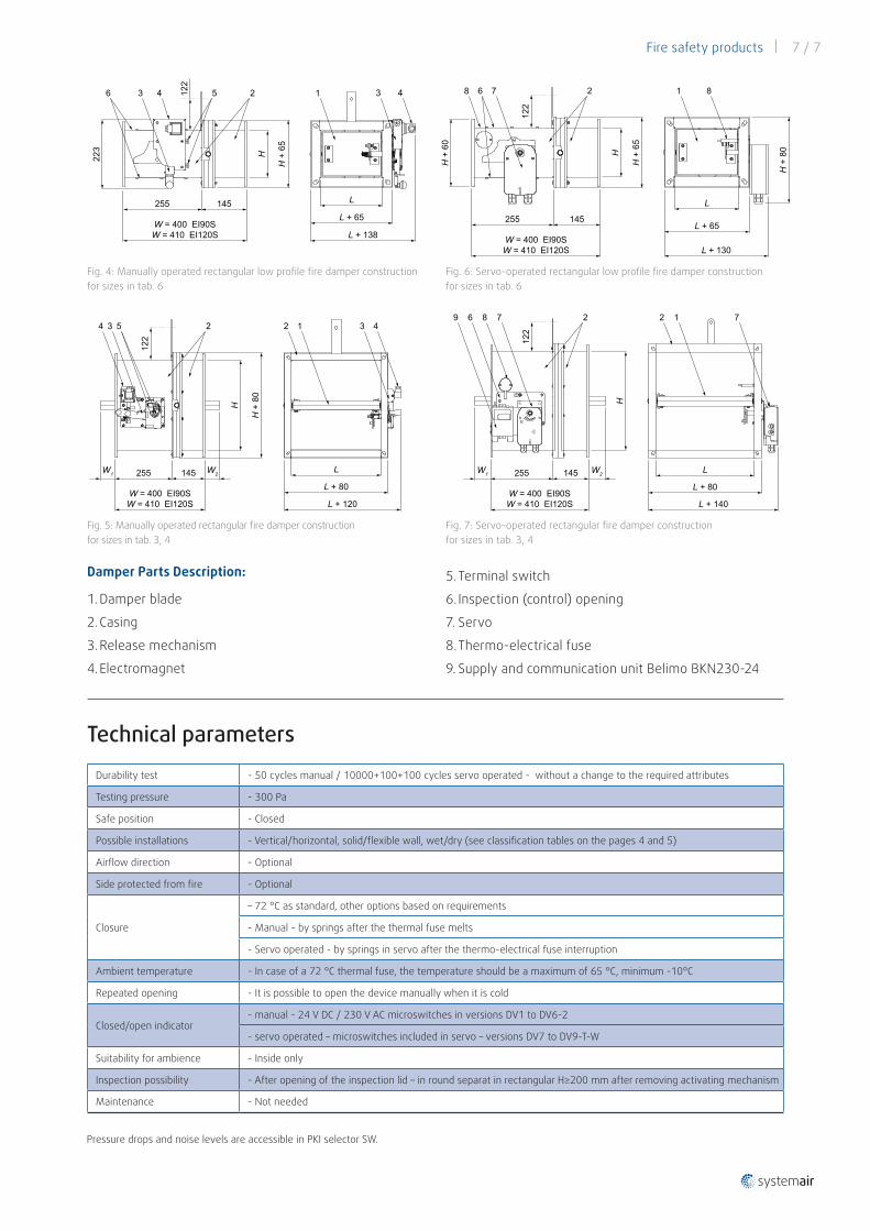
Damper Parts Description:
1. Damper blade
2. Casing
3. Release mechanism
4. Electromagnet
5. Terminal switch
6. Inspection (control) opening
7. Servo
8. Thermo-electrical fuse
9. Supply and communication unit Belimo BKN230-24
PKIS-EI90S and EI120S
We offer a wide range of dampers and dimensions with fire resistance of 90 and 120 minutes for rectangular ductworks.
Rectangular fire dampers are certified according to the EN 15650, tested in accordance with the EN 1366-2 and classified according to the EN13501-3:
Name Range of actuator types Dimension range (mm) Installation Fire resistivity
PKIS EI90S ZV, DV1 to DV9-T-W
all supporting constructions: 100 × 100 to 1000 × 1000
Solid wall – wet or dry
EI 90 (ve ho i ↔ o) SFlexible wall – wet or dry rigid wall / ceiling:
100 × 100 to 1600 × 1000 Ceiling – wet
PKIS EI120S ZV, DV1 to DV9-T-W
all supporting constructions: 100 × 100* to 1000 × 1000
Solid wall – we
EI 120 (ve ho i ↔ o) SFlexible wall – wet rigid wall / ceiling:
100 × 100* to 1600 × 1000 Ceiling – wet
All rectangular fire dampers PKIS have CE certificate: 1396-CPD-0062* The pressure drop is very high by smaller then 200 × 200
6 / 7 | Fire safety products
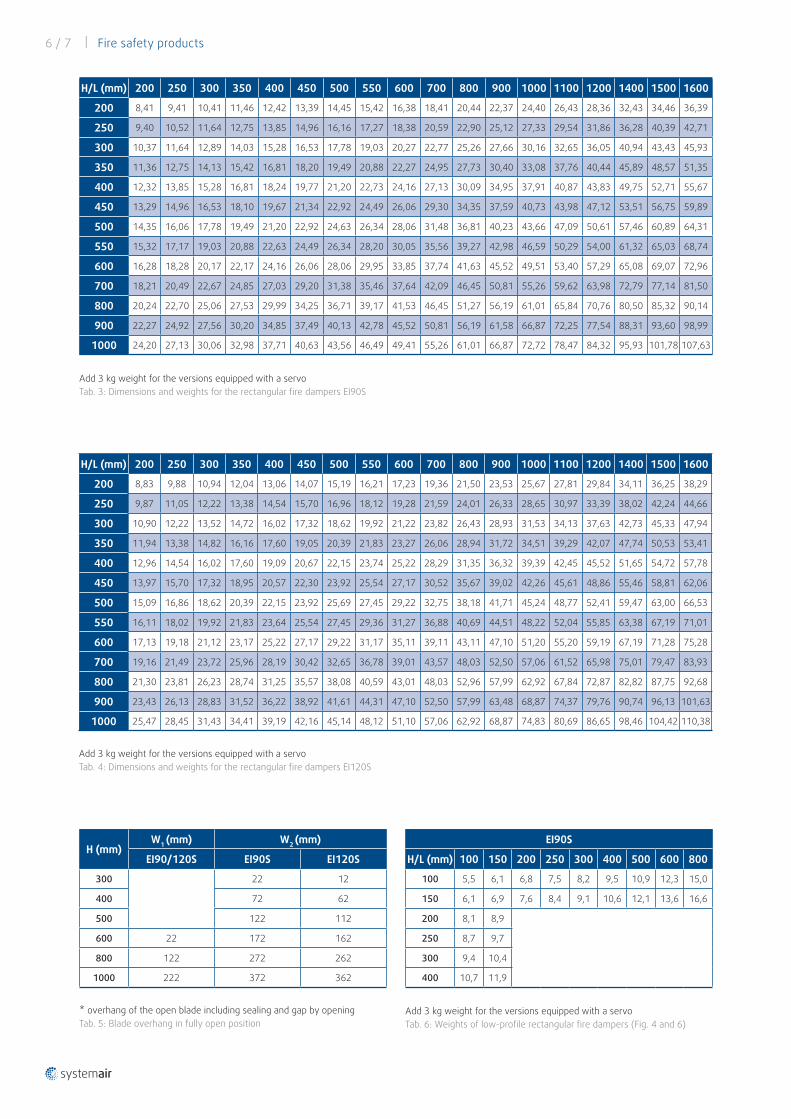
H/L (mm) 200 250 300 350 400 450 500 550 600 700 800 900 1000 1100 1200 1400 1500 1600
200 8,41 9,41 10,41 11,46 12,42 13,39 14,45 15,42 16,38 18,41 20,44 22,37 24,40 26,43 28,36 32,43 34,46 36,39
250 9,40 10,52 11,64 12,75 13,85 14,96 16,16 17,27 18,38 20,59 22,90 25,12 27,33 29,54 31,86 36,28 40,39 42,71
300 10,37 11,64 12,89 14,03 15,28 16,53 17,78 19,03 20,27 22,77 25,26 27,66 30,16 32,65 36,05 40,94 43,43 45,93
350 11,36 12,75 14,13 15,42 16,81 18,20 19,49 20,88 22,27 24,95 27,73 30,40 33,08 37,76 40,44 45,89 48,57 51,35
400 12,32 13,85 15,28 16,81 18,24 19,77 21,20 22,73 24,16 27,13 30,09 34,95 37,91 40,87 43,83 49,75 52,71 55,67
450 13,29 14,96 16,53 18,10 19,67 21,34 22,92 24,49 26,06 29,30 34,35 37,59 40,73 43,98 47,12 53,51 56,75 59,89
500 14,35 16,06 17,78 19,49 21,20 22,92 24,63 26,34 28,06 31,48 36,81 40,23 43,66 47,09 50,61 57,46 60,89 64,31
550 15,32 17,17 19,03 20,88 22,63 24,49 26,34 28,20 30,05 35,56 39,27 42,98 46,59 50,29 54,00 61,32 65,03 68,74
600 16,28 18,28 20,17 22,17 24,16 26,06 28,06 29,95 33,85 37,74 41,63 45,52 49,51 53,40 57,29 65,08 69,07 72,96
700 18,21 20,49 22,67 24,85 27,03 29,20 31,38 35,46 37,64 42,09 46,45 50,81 55,26 59,62 63,98 72,79 77,14 81,50
800 20,24 22,70 25,06 27,53 29,99 34,25 36,71 39,17 41,53 46,45 51,27 56,19 61,01 65,84 70,76 80,50 85,32 90,14
900 22,27 24,92 27,56 30,20 34,85 37,49 40,13 42,78 45,52 50,81 56,19 61,58 66,87 72,25 77,54 88,31 93,60 98,99
1000 24,20 27,13 30,06 32,98 37,71 40,63 43,56 46,49 49,41 55,26 61,01 66,87 72,72 78,47 84,32 95,93 101,78 107,63
H/L (mm) 200 250 300 350 400 450 500 550 600 700 800 900 1000 1100 1200 1400 1500 1600
200 8,83 9,88 10,94 12,04 13,06 14,07 15,19 16,21 17,23 19,36 21,50 23,53 25,67 27,81 29,84 34,11 36,25 38,29
250 9,87 11,05 12,22 13,38 14,54 15,70 16,96 18,12 19,28 21,59 24,01 26,33 28,65 30,97 33,39 38,02 42,24 44,66
300 10,90 12,22 13,52 14,72 16,02 17,32 18,62 19,92 21,22 23,82 26,43 28,93 31,53 34,13 37,63 42,73 45,33 47,94
350 11,94 13,38 14,82 16,16 17,60 19,05 20,39 21,83 23,27 26,06 28,94 31,72 34,51 39,29 42,07 47,74 50,53 53,41
400 12,96 14,54 16,02 17,60 19,09 20,67 22,15 23,74 25,22 28,29 31,35 36,32 39,39 42,45 45,52 51,65 54,72 57,78
450 13,97 15,70 17,32 18,95 20,57 22,30 23,92 25,54 27,17 30,52 35,67 39,02 42,26 45,61 48,86 55,46 58,81 62,06
500 15,09 16,86 18,62 20,39 22,15 23,92 25,69 27,45 29,22 32,75 38,18 41,71 45,24 48,77 52,41 59,47 63,00 66,53
550 16,11 18,02 19,92 21,83 23,64 25,54 27,45 29,36 31,27 36,88 40,69 44,51 48,22 52,04 55,85 63,38 67,19 71,01
600 17,13 19,18 21,12 23,17 25,22 27,17 29,22 31,17 35,11 39,11 43,11 47,10 51,20 55,20 59,19 67,19 71,28 75,28
700 19,16 21,49 23,72 25,96 28,19 30,42 32,65 36,78 39,01 43,57 48,03 52,50 57,06 61,52 65,98 75,01 79,47 83,93
800 21,30 23,81 26,23 28,74 31,25 35,57 38,08 40,59 43,01 48,03 52,96 57,99 62,92 67,84 72,87 82,82 87,75 92,68
900 23,43 26,13 28,83 31,52 36,22 38,92 41,61 44,31 47,10 52,50 57,99 63,48 68,87 74,37 79,76 90,74 96,13 101,63
1000 25,47 28,45 31,43 34,41 39,19 42,16 45,14 48,12 51,10 57,06 62,92 68,87 74,83 80,69 86,65 98,46 104,42 110,38
Add 3 kg weight for the versions equipped with a servoTab. 3: Dimensions and weights for the rectangular fire dampers EI90S
Add 3 kg weight for the versions equipped with a servoTab. 4: Dimensions and weights for the rectangular fire dampers EI120S
H (mm) W1 (mm) W2 (mm)
EI90/120S EI90S EI120S
300
22 12
400 72 62
500 122 112
600 22 172 162
800 122 272 262
1000 222 372 362
* overhang of the open blade including sealing and gap by openingTab. 5: Blade overhang in fully open position
EI90S
H/L (mm) 100 150 200 250 300 400 500 600 800
100 5,5 6,1 6,8 7,5 8,2 9,5 10,9 12,3 15,0
150 6,1 6,9 7,6 8,4 9,1 10,6 12,1 13,6 16,6
200 8,1 8,9
250 8,7 9,7
300 9,4 10,4
400 10,7 11,9
Add 3 kg weight for the versions equipped with a servoTab. 6: Weights of low-profile rectangular fire dampers (Fig. 4 and 6)
Fire safety products | 7 / 7
Damper Parts Description:
1. Damper blade
2. Casing
3. Release mechanism
4. Electromagnet
W1
W = 400 EI90SW = 410 EI120S
145255
H
H +
80
L
L + 80
L + 120
W2
122
4 3 25 2 1 3 4
L
L + 65
H +
65
H
W = 400 EI90SW = 410 EI120S
255 145
L + 138
223
122
6 3 4 5 2 1 3 4
H
W2145255
W = 400 EI90SW = 410 EI120S
122
L
L + 80
L + 140
W1
869 7 2 2 1 7
Fig. 4: Manually operated rectangular low profile fire damper construction for sizes in tab. 6
Fig. 5: Manually operated rectangular fire damper construction for sizes in tab. 3, 4
Fig. 6: Servo-operated rectangular low profile fire damper construction for sizes in tab. 6
Fig. 7: Servo-operated rectangular fire damper construction for sizes in tab. 3, 4
Durability test - 50 cycles manual / 10000+100+100 cycles servo operated - without a change to the required attributes
Testing pressure - 300 Pa
Safe position - Closed
Possible installations - Vertical/horizontal, solid/flexible wall, wet/dry (see classification tables on the pages 4 and 5)
Airflow direction - Optional
Side protected from fire - Optional
Closure
– 72 °C as standard, other options based on requirements
- Manual - by springs after the thermal fuse melts
- Servo operated - by springs in servo after the thermo-electrical fuse interruption
Ambient temperature - In case of a 72 °C thermal fuse, the temperature should be a maximum of 65 °C, minimum -10°C
Repeated opening - It is possible to open the device manually when it is cold
Closed/open indicator - manual - 24 V DC / 230 V AC microswitches in versions DV1 to DV6-2
- servo operated – microswitches included in servo – versions DV7 to DV9-T-W
Suitability for ambience - Inside only
Inspection possibility - After opening of the inspection lid – in round separat in rectangular H≥200 mm after removing activating mechanism
Maintenance - Not needed
Technical parameters
5. Terminal switch
6. Inspection (control) opening
7. Servo
8. Thermo-electrical fuse
9. Supply and communication unit Belimo BKN230-24
Pressure drops and noise levels are accessible in PKI selector SW.
L
L + 65
H +
65
H
W = 400 EI90SW = 410 EI120S
255 145
L + 130
H +
80
122
8 6 7 2 1 8
H +
60