Embed Size (px)
Citation preview

SCHLAGEL, INC. EDI DISTRIBUTOR CONTROL
UIO Scanner User Manual
For Modbus RTU and DF1 Protocols
UIO_SM 12/15/10

SCHLAGEL, INC. EDI DISTRIBUTOR CONTROL
Page 2
Typical Scanner System Layout
Figure 1 Scanner system layout and component and connection identification.
A complete EDI Scanner system is shown in Figure 1. It consists of 1 to 20 EDI drive controls connected as nodes to the EDINet network, the UIO module, a PLC and the cables that interconnects these components.
The EDINet network may be laid out using the daisy-chain or hub method, or a combination of both. The hub method is preferred because disconnecting any node does not interfere with the rest of the network. The UIO and UCOM boards are provided with RJ12 sockets and screw terminations for the Cat 5 cable connections. See the UIO Installation Manual for details on these connections.
The following list identifies the network connection components shown if Figure 1.
1. Cat 5 cable with RJ12 plugs. Available in 5’, 10’, 15’, 25’ and 50’ lengths.
2. 6 port or 12 port optional hub.
3. 18” ribbon cable with DB-9 M & F connections.
4. UIO Module. Usually placed near the PLC.
5. UCOM or RS485 adapter board on EDI control.
6. Cat 5 cable. Maximum of 4000’ from the UIO to the first EDI control
Please note that we have desktop simulators that are available for a 30 day period, to assist you in the configuration and programming of the UIO and PLC prior to site installation. A fully refundable deposit is required. Our technical support team is available to answer any questions you may have regarding the simulator..
2 1
1 4
3 5
6

SCHLAGEL, INC. EDI DISTRIBUTOR CONTROL
Page 3
Network and Scanner Concepts
All EDI-V5 distributor drive controls can be configured to be a member of a network of up to 20 controls. This network, referred to as EDINet, is a RS485 multidrop-based system with a special communication protocol. Older EDI controls that are configured for networking can also be part of this network
All EDI drive controls on the EDINet act as slaves in a master/slave arrangement that requires an intelligent master, in this case the UIO. Each drive has a unique single character name, or address, to identify itself on the network and can only communicate with the master, never with other slaves. All communication must be initiated by the master, specifically identifying the slave it wishes to talk to by its address. Being a member of the network does not interfere with the normal keypad terminal functions of an operator at the EDI control.
The EDINet protocol allows the EDI drive to be queried for position and error status, and can receive instructions to change position.
The most common reason for selecting the EDINet is to allow a PLC to control all of the distributor drives. It is a daunting task, and waste of PLC resources, to write a ladder-logic program to query the status of each distributor, reposition them when necessary and keep track of them during operation.
The UIO Scanner Mode was developed as an intelligent master to discover all drives on the network, determine their status, convey this information to certain PLC registers, read any requests by the PLC to change a distributor position and then instruct the proper distributor drives to reposition as necessary…all without writing a single rung of code. This is accomplished by using either the Modbus RTU or DF1 protocol to talk with the PLC.
In practice, the UIO also acts as a master to the PLC, which acts as a slave. The PLC only responds to messages sent from the UIO. The PLC never needs to initiate a message.
The UIO connects to a PLC via a RS232 serial port capable of communicating with the selected protocol. The UIO is configured to use 40 contiguous integer registers starting at a user defined Base Register. The first 20 registers are used for writing the status of each distributor position. The next 20 registers are read by the UIO and reflect the positions requested by the PLC. The UIO then directs any distributor repositioning necessary.
To assist the installation and troubleshooting process, the 2-digit display on the UIO shows the number of distributors discovered on the EDINet. In addition, the first 16 active addresses are displayed on the LEDs near the bottom of the UIO.
Each EDI control must have its network option turned on and an address character assigned. Legal characters are A through U (S cannot be used). It is a good idea to keep the addresses sequential, starting with A. Be careful not to duplicate an address as unpredictable results will occur.
Instructions on enabling the network and assigning addresses are covered in the EDI-V5 Installation Manual in the section “How To Use Option Codes”.
EDI Network Overview
UIO Scanner Overview
EDI Control Network Setup
SCHLAGEL, INC. EDI DISTRIBUTOR CONTROL
Page 4
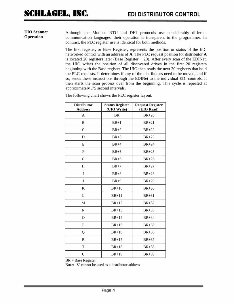
Although the Modbus RTU and DF1 protocols use considerably different communication languages, their operation is transparent to the programmer. In contrast, the PLC register use is identical for both methods.
The first register, or Base Register, represents the position or status of the EDI networked control with an address of A. The PLC request position for distributor A is located 20 registers later (Base Register + 20). After every scan of the EDINet, the UIO writes the position of all discovered drives in the first 20 registers beginning with the Base register. The UIO then reads the next 20 registers that hold the PLC requests. It determines if any of the distributors need to be moved, and if so, sends these instructions through the EDINet to the individual EDI controls. It then starts the scan process over from the beginning. This cycle is repeated at approximately .75 second intervals.
The following chart shows the PLC register layout.
BR = Base Register Note: ‘S’ cannot be used as a distributor address
Distributor Address
Status Register (UIO Write)
Request Register (UIO Read)
A BR BR+20
B BR+1 BR+21
C BR+2 BR+22
D BR+3 BR+23
E BR+4 BR+24
F BR+5 BR+25
G BR+6 BR+26
H BR+7 BR+27
I BR+8 BR+28
J BR+9 BR+29
K BR+10 BR+30
L BR+11 BR+31
M BR+12 BR+32
N BR+13 BR+33
O BR+14 BR+34
P BR+15 BR+35
Q BR+16 BR+36
R BR+17 BR+37
T BR+18 BR+38
U BR+19 BR+39
UIO Scanner Operation

SCHLAGEL, INC. EDI DISTRIBUTOR CONTROL
Page 5
The next chart shows examples of PLC register values and their meaning.
Status Register
Request Register Description Action
0 X No distributor drive was discovered at this address
None
100 X The distributor control is in Power-up or Reset mode
None
101 – 162 X The distributor is in motion. * None
1 - 62 0 The distributor is confirmed in position. (The maximum number of ducts on an EDI distributor is 62)
None. The position can be changed at the control keypad because there is no PLC request for positioning.
2 8
Example: Distributor is confirmed in position. 2. The PLC has just changed the request register to 8.
On the next scan, an instruction will be sent to the distributor, by the UIO, to change to position 8.
103 104 …
107
8
Example: The distributor is in motion, moving to position 8.
108 8
Example: The distributor is now near position 8 but has not stopped and confirmed its position as yet.
8 8 Example: The distributor is confirmed to be in position 8 as requested by the PLC.
As long as these registers are equal the PLC allows the distributor to be used. An alarm should be raised if a mismatch occurs.
X = Don’t care. * If the status register does not change in a few seconds, it can be assumed that a drive error for that distributor has occurred.
Status register values from 1 to 62 indicate the position of the distributor and that the position has been reached without error. If it is not in a confirmed position, or is presently moving, or is in an error mode, a value of 100 is added to the approximate spout position.
Note: All errors must be cleared by the EDI control terminal keypad.
EDI controls, particularly the EDI-V5 release, as well as the EDINet, and the UIO module, are very robust components. Error checking and reporting is taken into consideration in every facet of the combined operation and are promptly reported as discussed above.
One way to enhance the reliability of the UIO is to power it with the PLCs 24V logic supply. If the PLC goes down, who cares if the UIO is running? The keypad terminals at the control may still operate the distributors. The UIO can accept any AC or DC power input between 7 and 50 volts and requires less than 40 mA of current.
Finally, in the unlikely event someone unplugged the UIO or serial communication cable to the PLC, the UIO would shut down and the status registers would keep their present values indefinitely. To detect this event, the concerned programmer could set an unused status register, say Base Register +19, to a value of 1. This register will be set to 0 on every UIO scan. Pairing this register with a 2 second timer would raise an error if it were not cleared to 0 before the timer expired.
Reliability Issues

SCHLAGEL, INC. EDI DISTRIBUTOR CONTROL
Page 6
It can be frustrating getting unfamiliar components to work with your automation system. But that is only part of the job. The most important part is understanding what these devices do and how to make the best use of them in your program.
We have spent a lot of time trying to keep your part of the process to a minimum. Configuring the UIO and connecting it to the PLC is very straightforward (See the Appendixes for examples). The only decision to make during configuration is where you want to put the data in the PLC’s memory. The harder part is figuring out what the data means and how to incorporate it into the overall plan. Our Dual Desktop Simulator is a valuable tool to use in understanding how you want to use the data when programming the system. You will be supprised at the rapid learning curve you will experience with the simulator, even if you start from scratch.
When developing the drivers for the UIO we discovered an extremely valuable PC utility called mod_RSsim written by Conrad Braam. This utility simulates a PLC for both Modbus and DF1 slaves. One of the best things about the program is that our driver development could be done anywhere and anytime without the need of a PLC for testing. Once the drivers proved themselves on mod_RSsim, they always worked on the PLCs.
We suggest that anyone wishing to familiarize themselves with the UIO scanner operation and how it works with the EDI controls and PLC, download the mod_RSsim program and use it for experimenting with the EDI Simulator. Doing it this way, the concepts of implementing the distributor automation will be understood long before the PLC is connected.
The mod_RSsim program is free of charge and is available at http://www.plcsimulator.org. Conrad will send you a free registration key to eliminate a nag screen if you contact him at [email protected].
Planning the Integration

SCHLAGEL, INC. EDI DISTRIBUTOR CONTROL
Page 7
Appendex A
Use this procedure to setup a DF1 to UIO interface for an Allen-Bradley MicroLogix 1400 PLC. DF1 is the perfered protocol for A-B controllers.
We assume the following hardware and software is available and working:
§ Our Dual Simulator with UIO. This should be setup with both drives set for networking and using addresses A and P. The simulator includes a serial cable (straight through) and power supply.
§ A PC with an available serial port with a DB9-M connector.
§ The UIO_Cfg.exe configuration program for the UIO.
§ A MicroLogix 1400 and RSLogix500 programming software linked by Ethernet.
First configure the UIO.
1. Connect the UIO to the PC with the serial cable and run the UIO_Cfg.exe program. Refer to the UIO configuration section of the UIO Operation Manual for detailed instructions.
2. Select the correct COM port in the pulldown box. If it is not shown it is probably because it is being used by another program. It could be RSLinx running in the background or the PC needs a re-boot.
3. Press the connect button. You now have a few seconds to press the red reset button on the UIO. When communication is established between the PC and UIO the left selection menu will be enabled and the current mode of the UIO will be selected.
4. Select the Net DF1 Scanner – (P5) radio button and set the parameters to the values shown below.
5. Click Save CFG to UIO and.reset the UIO again.
You could have chosen a different file number, for example 31. Using RSLogix500, you would have to create File 31 as an integer file with at least 40 elements. Then all data values would be in file N31:0 thru N31:39.
The UIO is now scanning the EDINet and attempting to communicate with the PLC. The A and P LEDs on the UIO should be lit.
Connecting a UIO to MicroLogix 1400 using DF1

SCHLAGEL, INC. EDI DISTRIBUTOR CONTROL
Page 8
Configuring the PLC using RSLogix 500 software.
6. Unplug the serial cable from the PC and plug it into the Channel 2 port on the PLC.
7. In the Channel Configuration menu, select the Channel 2 tab. Change the values to match those shown below.
8. Click Apply, then OK.
9. In the Project Tree menu select File N7. Configure it for at least 40 integer elements and save it.
10. Download the setup and go online.
That’s it. Open the N7 file with the Data Monitor. N7:0 will hold the value of the A drive and N7:15 will show the value of the P drive. Now enter a legal duct position value for the A drive in N7:20 (0+20) and watch N7:0, and the simulator, move to comply. Do the same with N7:35 (15+20) for the P drive.
Not one rung of programming was necessary.

SCHLAGEL, INC. EDI DISTRIBUTOR CONTROL
Page 9
Notice that if N7:20 is left at 0, the A drive can be positioned at the keypad and is considered to be in Manual Mode. If, however, you leave a 3 in N7:20 and change to position 5 at the keypad, the drive will position per the keypad instruction and then go back to position 3.
Options:
If you want to use file N31 for the EDINet values, create it with RSLogix with 40 or more integer elements. In step 4 above, change the File Number to 31. If you would like to use N31:20 through N31:39, change the Base Register 20. Make sure you have allocated enough elements in file N31 to do this.
Troubles?
If you are like most of us, some stupid thing will prevent proper communication. Make sure it is not one of the steps above.
Check the Channel 2 tab of the Channel Status dialog window. Clear any errors that have developed and make sure the message count is incrementing.
What’s next?
The UIO Scanner User Manual has a lot of information on how the registers should be used and tips for using them. That manual is intended specifically for those using the DF1 or Modbus scanner modes of the UIO.

SCHLAGEL, INC. EDI DISTRIBUTOR CONTROL
Page 10
Appendex B
This paper will explain a procedure to setup a Modbus interface between the UIO and a MicroLogix 1400 PLC. DF1 is the prefered protocol for Allen-Bradley PLCs but some, like the 1400, have support for Modbus. Just to prove it works you may want to try this exersize.
We assume the following hardware and software is available and working:
• Our Dual Simulator with UIO. This should be setup with both drives set for networking and using addresses A and P. The simulator includes a serial cable (straight through) and power supply.
• A PC with an available serial port with a DB9-M connector.
• The UIO_Cfg.exe configuration program for the UIO.
• A MicroLogix 1400 and RSLogix500 programming software linked by Ethernet.
First configure the UIO.
1. Connect the UIO to the PC with the serial cable and run the UIO_Cfg.exe program. Refer to the UIO configuration section of the UIO Operation Manual for detailed instructions.
2. Select the correct COM port in the pulldown box. If it is not shown it is probably because it is being used by another program. It could be RSLinx running in the background or the PC needs a re-boot.
3. Press the connect button. You now have a few seconds to press the red reset button on the UIO. When communication is established between the PC and UIO the left selection menu will be enabled and the current mode of the UIO will be selected.
4. Select the Net Modbus Scanner – (P4) radio button and set the parameters to the values shown below.
5. Click Save CFG to UIO and exit the program. Reset the UIO again.
The UIO is now scanning the EDINet and attempting to communicate with a Modbus slave. The A and P LEDs on the UIO should be lit.
Connecting a UIO to MicroLogix 1400 using Modbus

SCHLAGEL, INC. EDI DISTRIBUTOR CONTROL
Page 11
Configuration of the PLC is next.
6. Load RSLogix500 and confirm the connection.
7. Unplug the serial cable from the PC and plug it into the Channel 2 port on the PLC.
8. In the Channel Configuration menu, select the Channel 2 tab. Change the values to match those shown below.
9. Click Apply, then OK.
10. In the Project Tree menu select File N7. Configure it for at least 40 integer elements and save it.
11. Download the setup and go online.

SCHLAGEL, INC. EDI DISTRIBUTOR CONTROL
Page 12
That’s it. Open the N7 file with the Data Viewer. N7:0 will hold the value of the A drive and N7:15 will show the value of the P drive. Now enter a legal duct position value for the A drive in N7:20 (0+20) and watch N7:0, and the simulator, move to comply. Do the same with N7:35 (15+20) for the P drive.
Not one rung of programming was necessary.
Notice that if N7:20 is left at 0, the A drive can be positioned at the keypad and is considered to be in Manual Mode. If, however, you leave a 3 in N7:20 and change to position 5 at the keypad, the drive will position per the keypad instruction and then go back to position 3.
Options:
If you want to use file N31 for the EDINet values, create it with RSLogix with 40 or more integer elements. Then, in the Channel Configuration menu, set the Holding Registers (4xxxx) to 31.
If you would like to use N31:20 through N31:39, change the base register in UIO_Cfg to 40021.
Troubles?
If you are like most of us, some stupid thing will prevent proper communication. Make sure it is not one of the steps above.
Check the Channel 2 tab of the Channel Status dialog window. Clear any errors that have developed and make sure the message count is incrementing.
What’s next?
The UIO Scanner User Manual has a lot of information on how the registers should be used and tips for using them. That manual is intended specifically for those using the DF1 or Modbus scanner modes of the UIO.
Schlagel, Inc.
491 N. Emerson Cambridge MN 55008
763-689-5991 800-328-8002 Fax 763-689-5310
[email protected] www.schlagel.com