Embed Size (px)
Citation preview
WELDING GUIDEWEAR PARTS
HENSLEY...YOUR WEAR SOLUTIONS SPECIALIST | WWW.HENSLEYIND.COM 32
TABLE OF CONTENTSIntroduction ......................................................................4
Preparation Of The Plate Steel And The Steel Castings .... 5
SECTION I: WELDING PROCESSESFiller Materials .................................................................... 7 Electrical Characteristics ...................................................8Welding Symbols ................................................................8Welding Position ................................................................ 11Preheat And Interpass Temperatures.............................12Welding Technique ............................................................13General Weld Crack Repair Instructions .........................14
SECTION II: WELDING GUIDES 1. J-Bolt Weld Bases .................................................15
2. Bucket Heel Shrouds ......................................... 18
Hensley Industries has been supplying spare parts to heavy equipment distributors since 1947. Over the years, our highly skilled staff has developed an expertise in the development and manufacture of these products. Today, we are proud to offer a complete line of ground engaging tools, buckets, cutting edges, and specialty attachments. We are committed to offering a superior level of service and the highest quality products in the world.
HENSLEY...YOUR WEAR SOLUTIONS SPECIALIST | WWW.HENSLEYIND.COM 32
3. Wear Runner Bases .......................................... 20
4. Lip Shrouds .........................................................23Bimetallic Welding Details .....................................26Bolt-On End Cap Installation /Removal Instruction ................................................ 27
SECTION III: WELDING TERMS AND DEFINITIONS
HENSLEY...YOUR WEAR SOLUTIONS SPECIALIST | WWW.HENSLEYIND.COM 54
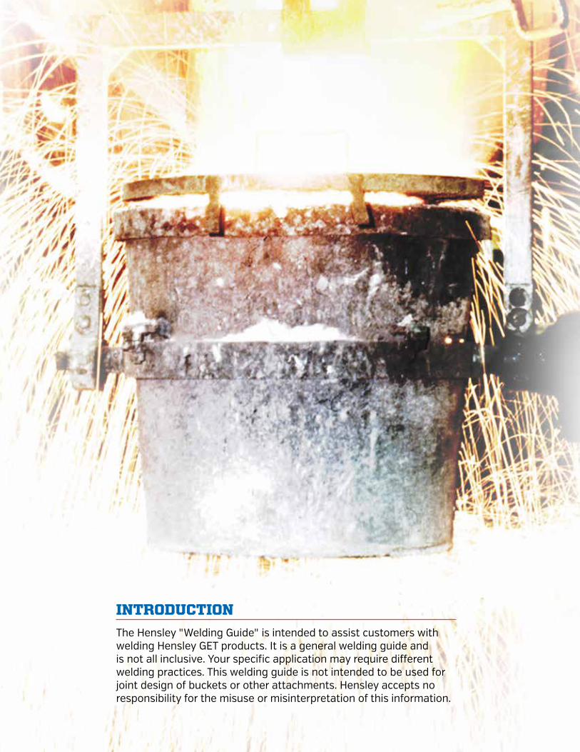
INTRODUCTION
The Hensley "Welding Guide" is intended to assist customers with welding Hensley GET products. It is a general welding guide and is not all inclusive. Your specific application may require different welding practices. This welding guide is not intended to be used for joint design of buckets or other attachments. Hensley accepts no responsibility for the misuse or misinterpretation of this information.
HENSLEY...YOUR WEAR SOLUTIONS SPECIALIST | WWW.HENSLEYIND.COM 54
PREPARATION OF THE PLATE STEEL AND THE STEEL CASTINGSThe surfaces to be welded must be free from scale, grease, paint, water, etc. The basis here is to provide a good surface for welding. This is a very good practice and is mentioned in all welding codes including AWS 14.3, the "Specification for Welding Earthmoving and Construction Equipment". The surfaces must be sufficiently clean so that there is nothing that might contain hydrocarbons, which break down in the heat of the arc producing hydrogen, which can be absorbed in the weld and cause cracks. Preparation of the weld surfaces may be achieved by sand blasting, shot blasting, grinding, sanding, air carbon arc gouging, or a combination of any these process.
In a new fabrication, rebuild, or a conversion, there can be gaps between the adapters and the plate lip. Gaps that are no greater than 3/32" / 2.4mm require no additional work, just good sound welding techniques. Gaps that are greater than 3/32" / 2.4mm, should be dealt with in the following manner:
1. Preheat adapter leg to 300°F / 150°C.
2. Deposit stringer bead(s) on the landing of the adapter to reduce the gap condition.
3. Grind weld so that there is a smooth transition in the weld groove area of the adapter.
4. Check fit adapter on lip – grind or weld as required to eliminate gap condition.
If the throat opening of the adapter is too narrow to fit the lip, grinding of the land at the bottom of the weld groove is permissible. If more than 1/8" / 3.2mm is removed from the land, the weld groove needs to be widened to achieve the original weld groove size.
Welding may be done by any of the following processes:
HENSLEY...YOUR WEAR SOLUTIONS SPECIALIST | WWW.HENSLEYIND.COM 76
SECTION I: WELDING
PROCESSES

HENSLEY...YOUR WEAR SOLUTIONS SPECIALIST | WWW.HENSLEYIND.COM 76
Shielded metal arc welding (SMAW)
Gas metal arc welding (GMAW)
Flux-cored arc welding (FCAW)
A combination of SMAW and GMAW or FCAW can be employed.
FILLER MATERIALS
FILLER MATERIALSProcess AWS JIS NF DIN BS Shielding Gas
SMAW E7018 AWS A5.1
JIS Z3212 D5016
E515B12029(H) NF A 81 309
E51B10120 DIN 8556
E515B12029(H) BS 2926 N/A
GMAW ER 70S-6 AWS A5.18
JIS Z3312 YGW12
GS 2 NF A 81-311
SG2 DIN8559
A18 BS2901-1
100 CO2 90%Ar/8%CO2
GMAW E70C-6M AWS A5.18
JIS Z3313 YFW-A50DM
92%Ar/8%CO2 90%Ar/10%CO2
FCAW E70T-5 AWS A5.20
JIS Z3313 YFW-C50DM
TGS 51 3.3 BH NF A 81-350
SG B1 CY4254 DIN
8559
T530 GBH BS7084
100% CO2 75%Ar/25%CO2
FCAW E71T-1 AWS A5.2
JIS Z3312 YFW-C50DR
TGS 51 3.3 BH NF A 81-350
SG B1 CY4254 DIN
8559
T530 GBH BS7084
100%CO2 75%Ar/25%CO2 90%Ar/10%CO2

HENSLEY...YOUR WEAR SOLUTIONS SPECIALIST | WWW.HENSLEYIND.COM 98
ELECTRICAL CHARACTERISTICSA. Polarity
All welding shall be done using direct current electrode positive (DCEP).
B. Current and Voltage Ranges
SMAW
Electrode Diameter Amperes
2.4mm / 3/32 in. 65 to 120
3.2mm / 1/8 in. 80 to 160
4.0mm / 5/32 in. 115 to 220
4.8mm / 3/16 in. 140 to 300
GMAW AND FCAW
Electrode Diameter Voltage Amperes
1.2mm / 0.045 in 22 to 30 220 to 320
1.4 mm / 0.052 in. 25 to 30 250 to 325
1.6mm / 1/16 in. 25 to 35 250 to 360
2.4mm / 3/32 in 28 to 35 350 to 450
WELDING SYMBOLSWeld symbols are used as a type of shorthand to indicate the type of weld, its size and other processing and finishing information. The following section will introduce you to the most common symbols you may encounter, while using our product, and their meaning. The complete set of symbols is given in a standard published by American National Standards Institute (ANSI) and the American Welding Society (AWS): ANSI/AWS A2.4, Symbols for Welding and Nondestructive Testing.
WELDING SYMBOL STRUCTURE
Field weld symbol
Tail Weld-all-around symbol
Arrow to joint
Weld Info for the “Other Side”
Weld Info for the “Arrow Side”
The horizontal line, called the reference line, is the anchor to which all the other welding symbols are tied. The instructions for making the weld are strung along the reference line. An arrow connects the reference line to the joint that is to be welded. The example above has the arrow growing out of the right end of the reference line and heading down to the right, but other combinations may be encountered.
HENSLEY...YOUR WEAR SOLUTIONS SPECIALIST | WWW.HENSLEYIND.COM 98
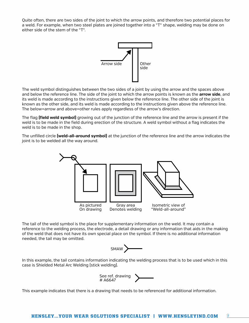
Quite often, there are two sides of the joint to which the arrow points, and therefore two potential places for a weld. For example, when two steel plates are joined together into a "T" shape, welding may be done on either side of the stem of the "T".
Arrow side Otherside
The weld symbol distinguishes between the two sides of a joint by using the arrow and the spaces above and below the reference line. The side of the joint to which the arrow points is known as the arrow side, and its weld is made according to the instructions given below the reference line. The other side of the joint is known as the other side, and its weld is made according to the instructions given above the reference line. The below=arrow and above=other rules apply regardless of the arrow's direction.
The flag (field weld symbol) growing out of the junction of the reference line and the arrow is present if the weld is to be made in the field during erection of the structure. A weld symbol without a flag indicates the weld is to be made in the shop.
The unfilled circle (weld-all-around symbol) at the junction of the reference line and the arrow indicates the joint is to be welded all the way around.
As picturedOn drawing
Gray areaDenotes welding
Isometric view of“Weld-all-around”
The tail of the weld symbol is the place for supplementary information on the weld. It may contain a reference to the welding process, the electrode, a detail drawing or any information that aids in the making of the weld that does not have its own special place on the symbol. If there is no additional information needed, the tail may be omitted.
SMAW
In this example, the tail contains information indicating the welding process that is to be used which in this case is Shielded Metal Arc Welding (stick welding).
This example indicates that there is a drawing that needs to be referenced for additional information.
See ref. drawing # A6647
HENSLEY...YOUR WEAR SOLUTIONS SPECIALIST | WWW.HENSLEYIND.COM 1110
TYPES OF WELDS AND THEIR SYMBOLS
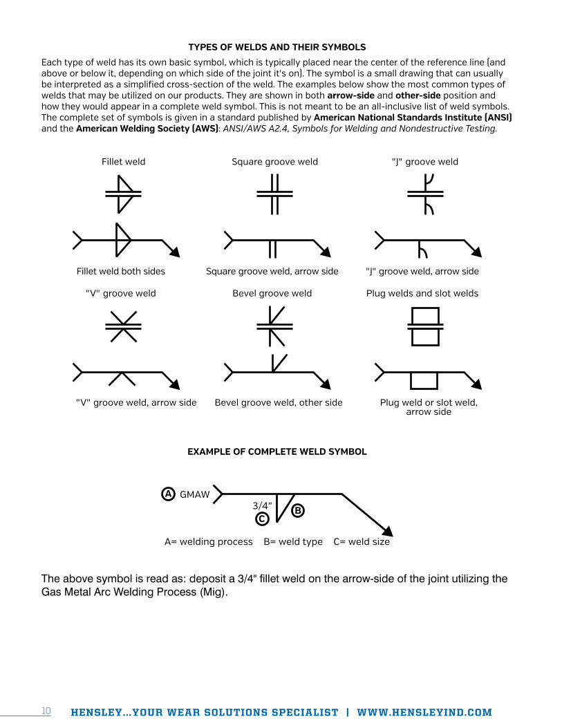
Each type of weld has its own basic symbol, which is typically placed near the center of the reference line (and above or below it, depending on which side of the joint it's on). The symbol is a small drawing that can usually be interpreted as a simplified cross-section of the weld. The examples below show the most common types of welds that may be utilized on our products. They are shown in both arrow-side and other-side position and how they would appear in a complete weld symbol. This is not meant to be an all-inclusive list of weld symbols. The complete set of symbols is given in a standard published by American National Standards Institute (ANSI) and the American Welding Society (AWS): ANSI/AWS A2.4, Symbols for Welding and Nondestructive Testing.
Fillet weld both sides Square groove weld, arrow side "J" groove weld, arrow side
Fillet weld Square groove weld "J" groove weld
"V" groove weld, arrow side Bevel groove weld, other side Plug weld or slot weld, arrow side
"V" groove weld Bevel groove weld Plug welds and slot welds
EXAMPLE OF COMPLETE WELD SYMBOL
GMAWA3/4”
CB
A= welding process B= weld type C= weld size
The above symbol is read as: deposit a 3/4" fillet weld on the arrow-side of the joint utilizing the Gas Metal Arc Welding Process (Mig).
HENSLEY...YOUR WEAR SOLUTIONS SPECIALIST | WWW.HENSLEYIND.COM 1110
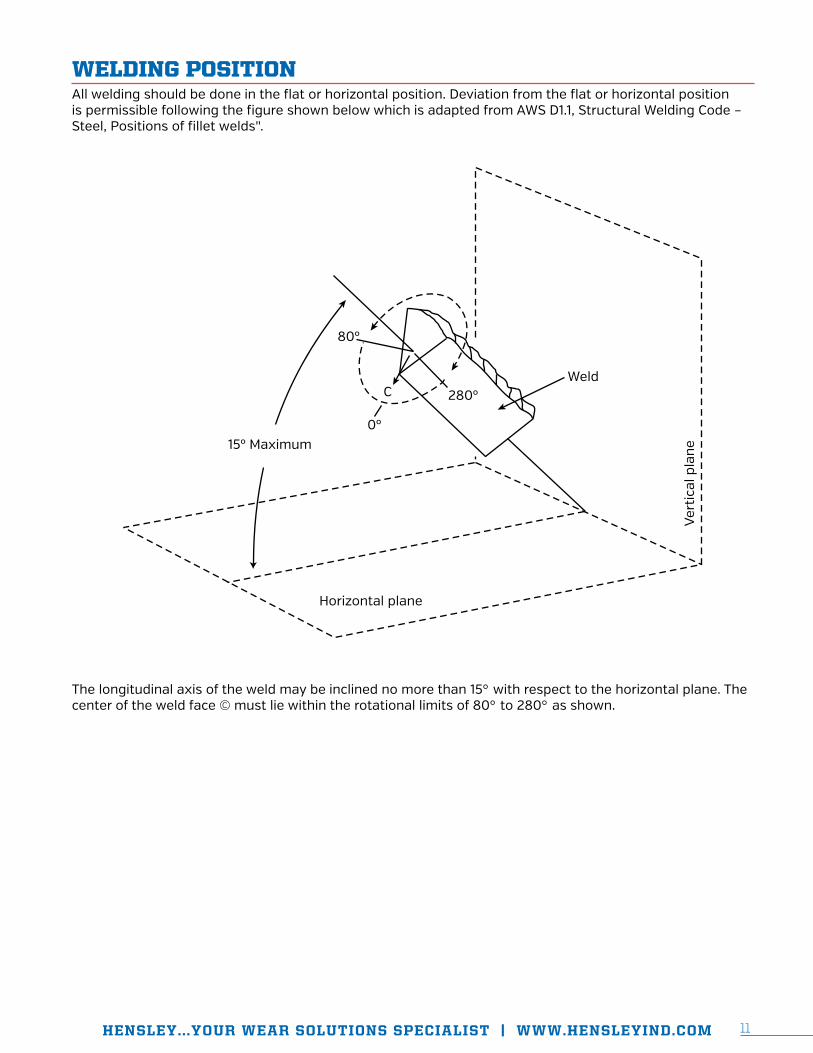
WELDING POSITIONAll welding should be done in the flat or horizontal position. Deviation from the flat or horizontal position is permissible following the figure shown below which is adapted from AWS D1.1, Structural Welding Code – Steel, Positions of fillet welds".
Ver
tica
l pla
ne
Weld280º
0º
C
80º
15º Maximum
Horizontal plane
The longitudinal axis of the weld may be inclined no more than 15° with respect to the horizontal plane. The center of the weld face © must lie within the rotational limits of 80° to 280° as shown.
HENSLEY...YOUR WEAR SOLUTIONS SPECIALIST | WWW.HENSLEYIND.COM 1312
PREHEAT AND INTERPASS TEMPERATURESPreheat is the application of heat to the work piece prior to welding, cutting, or gouging. All cutting and welding processes use a high temperature heat source. These high temperatures exceed the melting point of the base metal. This creates the problem of a traveling high temperature, localized heat source, and the effect that it has on the surrounding base metal.
A large temperature differential causes thermal expansion and contraction, high stresses, hardened areas, and a very small area for hydrogen gases to escape from the steel. Preheating will reduce the danger of weld cracking, reduce maximum hardness of the heat affected zone, minimize shrinkage stresses, lessen distortion, and create a larger area for hydrogen gases to escape from the metal.
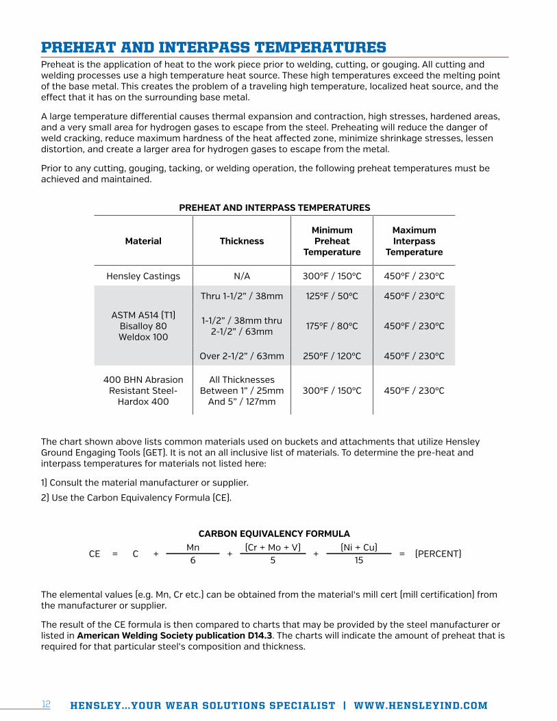
Prior to any cutting, gouging, tacking, or welding operation, the following preheat temperatures must be achieved and maintained.
PREHEAT AND INTERPASS TEMPERATURES
Material ThicknessMinimum Preheat
Temperature
Maximum Interpass
Temperature
Hensley Castings N/A 300ºF / 150ºC 450ºF / 230ºC
ASTM A514 (T1) Bisalloy 80 Weldox 100
Thru 1-1/2” / 38mm 125ºF / 50ºC 450ºF / 230ºC
1-1/2” / 38mm thru 2-1/2” / 63mm 175ºF / 80ºC 450ºF / 230ºC
Over 2-1/2” / 63mm 250ºF / 120ºC 450ºF / 230ºC
400 BHN Abrasion Resistant Steel-
Hardox 400
All Thicknesses Between 1” / 25mm
And 5” / 127mm300ºF / 150ºC 450ºF / 230ºC
The chart shown above lists common materials used on buckets and attachments that utilize Hensley Ground Engaging Tools (GET). It is not an all inclusive list of materials. To determine the pre-heat and interpass temperatures for materials not listed here:
1) Consult the material manufacturer or supplier.
2) Use the Carbon Equivalency Formula (CE).
CARBON EQUIVALENCY FORMULA
CE = C +Mn
+(Cr + Mo + V)
+(Ni + Cu)
= (PERCENT)6 5 15
The elemental values (e.g. Mn, Cr etc.) can be obtained from the material's mill cert (mill certification) from the manufacturer or supplier.
The result of the CE formula is then compared to charts that may be provided by the steel manufacturer or listed in American Welding Society publication D14.3. The charts will indicate the amount of preheat that is required for that particular steel's composition and thickness.
HENSLEY...YOUR WEAR SOLUTIONS SPECIALIST | WWW.HENSLEYIND.COM 1312
NOTE: If the ambient humidity is high and or the temperature is below 40°F / 4°C, the tabulated value should be increased by 80°F / 27°C. At no time should any material type or thickness be welded when the temperature of the steel is at or below 40°F / 4°C.
Preheating with burners or torches is much more effective when the heat is applied from the bottom side of the work piece with insulating blankets on the topside. The blankets help to disperse the heat evenly as well as retain the heat that has been input. Measure the temperature with a temperature indicating crayon or an infrared thermometer from the topside. This will insure that the preheat is not just on the surface of the material, but a complete preheat through the thickness of the materials to be welded. All material within 4" / 100mm of the weld zone must be within the specified temperature.
Cool slowly. Do not allow drafts or cool ambient temperatures to cool the parts or assembly. The part should be covered in a thermal blanket to insure a slow cool down rate.
WELDING TECHNIQUEStringer beads are recommended for higher strength and to minimize distortion. The use of weave or wash beads should not be used, however weaving is permitted to the extent that bead widths are no greater than 1/2" / 12mm.
Craters: When a weld pass is terminated within the finished product, the crater shall be filled to at least 85% of the full cross section of the weld. This will help eliminate the possibility of crater cracks. When welding with the SMAW process, the easiest way to achieve this is to stop the travel of the electrode and pause briefly before breaking the arc. When welding with the GMAW or FCAW processes, stop the travel and extinguish the arc, initiate the arc briefly, then extinguish.
Porosity: Porosity is a cavity-type discontinuity or defect that is formed by gas entrapment during solidification. Porosity reduces the strength of a weld and should be removed and replaced if the sum of the visual or surface porosity, including piping porosity, is greater that 1/4" / 6mm in any 4" / 100mm length of weld. A single void shall not exceed 1/16" / 1.6mm.
Overlap and Undercut: Weld overlap shall not exceed 1/16" / 1.6mm beyond the fusion line of the weld. Undercut shall not exceed 1/16" / 1.6mm in any joint or 10% of the base metal whichever is less. In addition, the accumulative length is not to exceed 1-1/2" / 38mm over a 24" / 610mm continuous section of weld.
Arc Strikes: A discontinuity resulting from a arc, consisting of any localized re-melted metal. Arc strikes should be avoided. Arc strikes that occur inside or outside the weld zone should be ground out.
Each weld shall merge smoothly into adjoining bead or base metal surface. Remove all unacceptable defects (crater cracks, porosity, overlap, undercut, etc.) on the weld surface or groove sidewalls before proceeding with the next weld pass. Removal may be accomplished by grinding with abrasive wheels, stones, or carbide burrs. Air carbon arc gouging may also be used, followed by grinding to remove all carbon slag.
Clean each pass of deposited weld metal before depositing the next weld pass. Using manual slag hammers, pneumatic needle gun, wire brushes or any combination of these tools may accomplish cleaning.
HENSLEY...YOUR WEAR SOLUTIONS SPECIALIST | WWW.HENSLEYIND.COM14
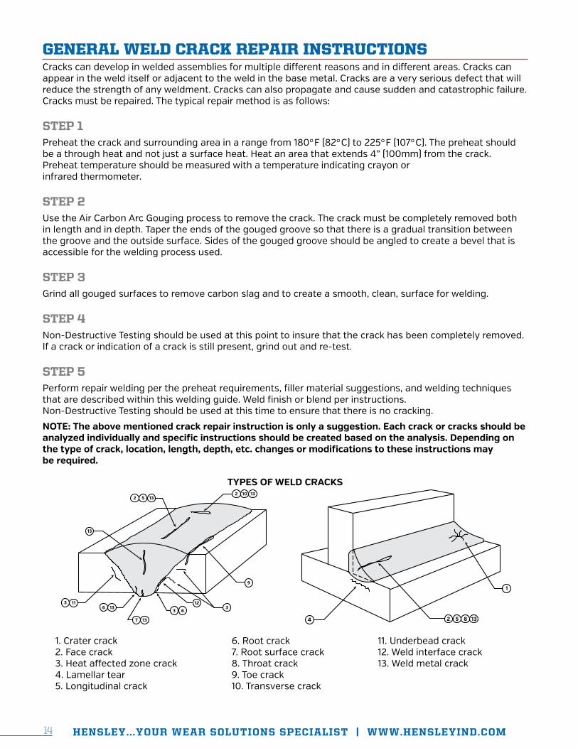
GENERAL WELD CRACK REPAIR INSTRUCTIONSCracks can develop in welded assemblies for multiple different reasons and in different areas. Cracks can appear in the weld itself or adjacent to the weld in the base metal. Cracks are a very serious defect that will reduce the strength of any weldment. Cracks can also propagate and cause sudden and catastrophic failure. Cracks must be repaired. The typical repair method is as follows:
STEP 1 Preheat the crack and surrounding area in a range from 180°F (82°C) to 225°F (107°C). The preheat should be a through heat and not just a surface heat. Heat an area that extends 4” (100mm) from the crack. Preheat temperature should be measured with a temperature indicating crayon or infrared thermometer.
STEP 2Use the Air Carbon Arc Gouging process to remove the crack. The crack must be completely removed both in length and in depth. Taper the ends of the gouged groove so that there is a gradual transition between the groove and the outside surface. Sides of the gouged groove should be angled to create a bevel that is accessible for the welding process used.
STEP 3Grind all gouged surfaces to remove carbon slag and to create a smooth, clean, surface for welding.
STEP 4Non-Destructive Testing should be used at this point to insure that the crack has been completely removed. If a crack or indication of a crack is still present, grind out and re-test.
STEP 5Perform repair welding per the preheat requirements, filler material suggestions, and welding techniques that are described within this welding guide. Weld finish or blend per instructions. Non-Destructive Testing should be used at this time to ensure that there is no cracking.
NOTE: The above mentioned crack repair instruction is only a suggestion. Each crack or cracks should be analyzed individually and specific instructions should be created based on the analysis. Depending on the type of crack, location, length, depth, etc. changes or modifications to these instructions may be required.
TYPES OF WELD CRACKS2
213
13
13
136
5
13
10
7
33
6
12113
9
2 5 8 134
1
1. Crater crack2. Face crack3. Heat affected zone crack4. Lamellar tear5. Longitudinal crack
6. Root crack7. Root surface crack8. Throat crack9. Toe crack10. Transverse crack
11. Underbead crack12. Weld interface crack13. Weld metal crack

SECTION II: WELDING
GUIDES
J-BOLT WELD
BASES

HENSLEY...YOUR WEAR SOLUTIONS SPECIALIST | WWW.HENSLEYIND.COM 1716
SPECIAL NOTES
Recommended filler material: AWS specification A5.1, class E7018, stick electrode. Stick electrodes should be kept in a heated rod oven at 250°F/110°C prior to use.
NOTE: See manufacturers recommended procedures for storage and preservation of low hydrogen electrodes.
Recommended weld types: Stringer beads are recommended for higher strength and less distortion. The use of weave or wash beads is NOT recommended and should not be used. Arc strikes should be avoided or ground down.
STEP 1Prior to welding, proper placement of the weld base must be determined (fig. 1.1). Position the weld base according to the adjacent chart (fig. 1.2) A deviation of ±3/32" (2.5 mm) is allowable. After placement has been confirmed, pre heat the base material to recommended temperatures (see Preheat and Interpass Temperature section for preheat temperature ranges) and tack weld the base at the rear along weld prep surface "A" (fig. 1.1).
See adjacent chart
Weld prepsurface "A"
WELD BASE PLACEMENT (± 3/32” (2.5mm) allowable)
Base Inches mm LSWB1 2.25 57 LSWB2 2.25 57 LSWB3 2.25 57 LSWB4 2.25 57 LSWB5 2.25 57 LSWB6 3.5 89 LSWB7 2.25 57 LSWB8 2.25 57 * LSWB9 FLUSH FLUSH * LSWB10 FLUSH FLUSH
STEP 2After the base is tacked, remove the shroud and re-establish the recommended preheat temperatures. Be sure to maintain this temperature throughout the welding process.
STEP 3Weld-out for the base should begin with the slot weld. A 1/2" (13mm) fillet weld should be deposited in this area (fig 3.1).
BE SURE THAT THE ENTIRE BOTTOM OF THE WELD BASE MAINTAINS CONTACT WITH THE LIP DURING THE ENTIRE WELD-OUT PROCESS.
SMAW1/2”(13mm)
BEFORE STARTING GAUGING, BE SURE TO READ ALL INSTRUCTIONS THOROUGHLY.
Fig 1.2 *See cast lip weld instructions
Fig 1.1
Fig 1.3

HENSLEY...YOUR WEAR SOLUTIONS SPECIALIST | WWW.HENSLEYIND.COM 1716
STEP 4Apply weld to the base perimeter next. Utilizing groove welds, fill the 1/2" (13mm) weld groove on the base completely (fig. 4.1 - fig. 4.2). Care must be taken at this point not to add too much weld. If joint is over welded, the weld material can interfere with the lip shroud. The idea is to add as much weld as possible to the base without causing interference with the lip shroud (fig. 4.3 - fig 4.4).
SMAW
SMAW
1/2”
Fig 4.1
SMAW
2 pl.2 pl.
SMAW
Fig 4.2
Weld
Maintain basecontact with lipLip
90º
NOWELD
NOWELD
Weld in this area will interfere with the front washer of the J-Bolt assembly which must �t �ush against the rear of the weld base.
Ensure contact with lip on entire length of weld base bottom surface as indicated.
Fig 4.3
WELDNO
WELD
Weld in the “NO WELD” areacan interfere with the lip shroud.
WELDNO
WELD
Fig 4.4
When the welding process has been completed, allow a slow cool down period to ambient temperature.
BEFORE STARTING GAUGING, BE SURE TO READ ALL INSTRUCTIONS THOROUGHLY.
SECTION II: WELDING
GUIDES
BUCKET
HEEL
SHROUDS
HENSLEY...YOUR WEAR SOLUTIONS SPECIALIST | WWW.HENSLEYIND.COM 19
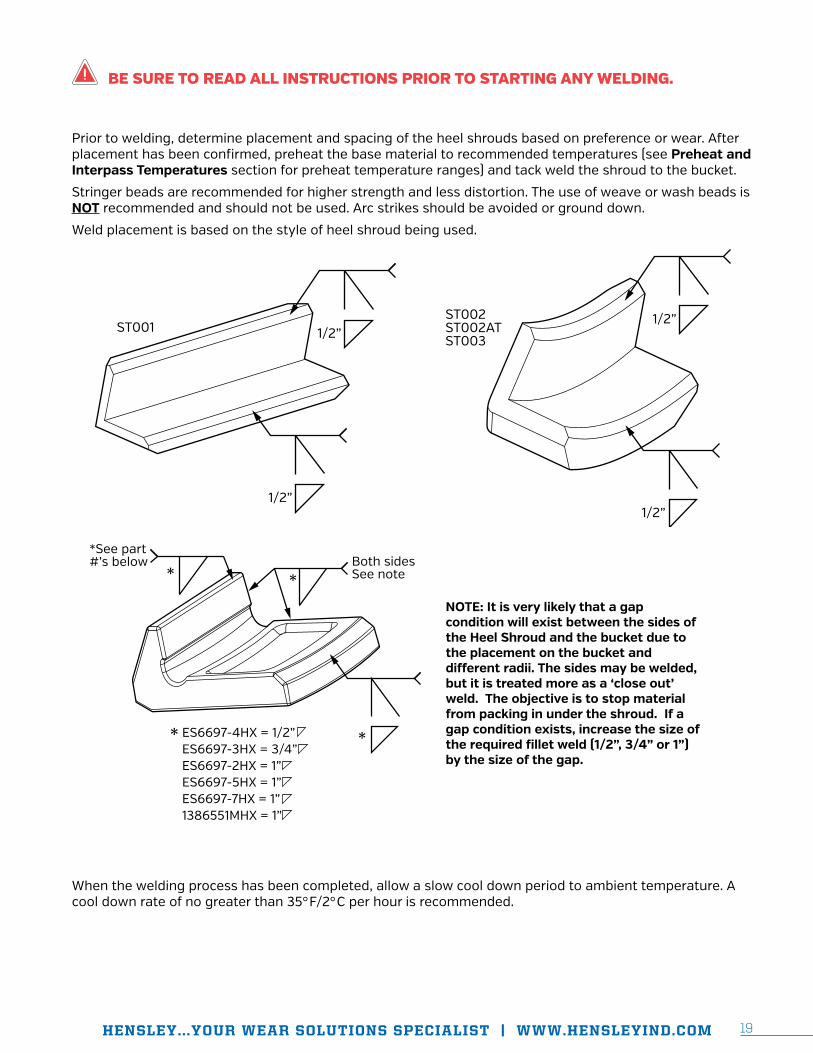
Prior to welding, determine placement and spacing of the heel shrouds based on preference or wear. After placement has been confirmed, preheat the base material to recommended temperatures (see Preheat and Interpass Temperatures section for preheat temperature ranges) and tack weld the shroud to the bucket.
Stringer beads are recommended for higher strength and less distortion. The use of weave or wash beads is NOT recommended and should not be used. Arc strikes should be avoided or ground down.
Weld placement is based on the style of heel shroud being used.
ST002ST002ATST003
1/2”
1/2”
ST001 1/2”
1/2”
*
*
*
*
Both sidesSee note
NOTE: It is very likely that a gap condition will exist between the sides of the Heel Shroud and the bucket due to the placement on the bucket and di�erent radii. The sides may be welded, but it is treated more as a ‘close out’ weld. The objective is to stop material from packing in under the shroud. If a gap condition exists, increase the size of the required �llet weld (1/2”, 3/4” or 1”) by the size of the gap.
*See part#’s below
ES6697-4HX = 1/2” ES6697-3HX = 3/4” ES6697-2HX = 1”ES6697-5HX = 1”ES6697-7HX = 1”1386551MHX = 1”
When the welding process has been completed, allow a slow cool down period to ambient temperature. A cool down rate of no greater than 35°F/2°C per hour is recommended.
BE SURE TO READ ALL INSTRUCTIONS PRIOR TO STARTING ANY WELDING.
SECTION II: WELDING
GUIDES
WEAR
RUNNER
BASES

HENSLEY...YOUR WEAR SOLUTIONS SPECIALIST | WWW.HENSLEYIND.COM 21
SPECIAL NOTES
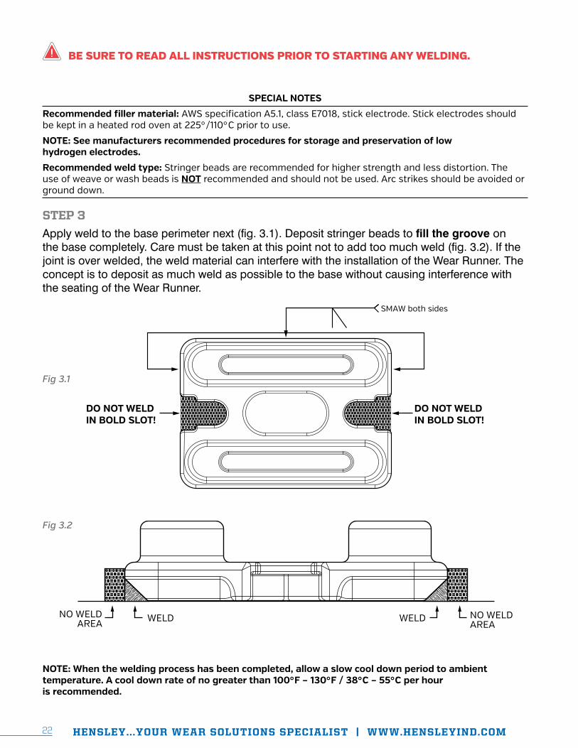
Recommended filler material: AWS specification A5.1, class E7018, stick electrode. Stick electrodes should be kept in a heated rod oven at 225°F/110°C prior to use.
NOTE: See manufacturers recommended procedures for storage and preservation of low hydrogen electrodes.
Recommended weld type: Stringer beads are recommended for higher strength and less distortion. The use of weave or wash beads is NOT recommended and should not be used. Arc strikes should be avoided or ground down.
STEP 1Position wear runner base in desired location making sure that there is clearance around the perimeter of the base for the Wear Runner. The surface that the wear runner based will be welded to should be clean and free from any impurities that will affect the strength of the weld. After placement has been confirmed, preheat the base material to recommended temperatures (see Preheat and Interpass Temperatures section for preheat temperature ranges) and tack weld in place.
STEP 2Weld-out for the base should begin with the slot area of the base. Deposit a ½" (13mm) fillet weld, all the way around (fig. 2.1).
1/2”SMAW
BE SURE TO READ ALL INSTRUCTIONS PRIOR TO STARTING ANY WELDING.
Fig 2.1
HENSLEY...YOUR WEAR SOLUTIONS SPECIALIST | WWW.HENSLEYIND.COM22
SPECIAL NOTES
Recommended filler material: AWS specification A5.1, class E7018, stick electrode. Stick electrodes should be kept in a heated rod oven at 225°/110°C prior to use.
NOTE: See manufacturers recommended procedures for storage and preservation of low hydrogen electrodes.
Recommended weld type: Stringer beads are recommended for higher strength and less distortion. The use of weave or wash beads is NOT recommended and should not be used. Arc strikes should be avoided or ground down.
STEP 3
Apply weld to the base perimeter next (fig. 3.1). Deposit stringer beads to fill the groove on the base completely. Care must be taken at this point not to add too much weld (fig. 3.2). If the joint is over welded, the weld material can interfere with the installation of the Wear Runner. The concept is to deposit as much weld as possible to the base without causing interference with the seating of the Wear Runner.
SMAW both sides
DO NOT WELDIN BOLD SLOT!
DO NOT WELDIN BOLD SLOT!
NO WELDAREA WELD NO WELD
AREAWELD
NOTE: When the welding process has been completed, allow a slow cool down period to ambient temperature. A cool down rate of no greater than 100°F – 130°F / 38°C – 55°C per hour is recommended.
BE SURE TO READ ALL INSTRUCTIONS PRIOR TO STARTING ANY WELDING.
Fig 3.1
Fig 3.2

BE SURE TO READ ALL INSTRUCTIONS PRIOR TO STARTING ANY WELDING.
SECTION II: WELDING
GUIDES
LIP
SHROUDS

HENSLEY...YOUR WEAR SOLUTIONS SPECIALIST | WWW.HENSLEYIND.COM 2524
All welding processes and filler materials listed in the 'Welding Processes' and 'Filler Materials' section of this publication are acceptable when welding these lip shrouds.
EXAMPLES OF SELECT SHROUD STYLES AND DEPOSITION OF WELD
STEP 1Locate shroud in desired position.
STEP 2Isolate preheat and tack weld.
WELD
WELD
*
2 Placestop & bottom
WELD
WELD
* 2 Placestop & bottom
* See chart for �llet weld size
WELD
WELD
*2 Placestop & bottom
BE SURE TO READ ALL INSTRUCTIONS PRIOR TO STARTING ANY WELDING.

HENSLEY...YOUR WEAR SOLUTIONS SPECIALIST | WWW.HENSLEYIND.COM 2524
STEP 3Fully preheat the lip material and lip shroud to recommended temperatures (see Preheat and Interpass Temperatures section for preheat temperature ranges).
STEP 4Complete weld-out as indicated. See chart for required fillet weld size by part number and type.
BE SURE TO READ ALL INSTRUCTIONS PRIOR TO STARTING ANY WELDING.
PART NUMBER TYPETOP FILLET WELD SIZE
INCHES (MM)
BOTTOM FILLET
WELD SIZE INCHES (MM)
10WSHX 1 3/8" (9) 1/2" (13)
13WSHX 1 1/2" (13) 1/2" (13)
14WS2HX 1 1/2" (13) 5/8" (16)
14WS-3230HX 1 5/8" (16) 5/8" (16)
14WS-32HX 1 1/2" (13) 5/8" (16)
14WSHX 1 5/8" (16) 5/8" (16)
18WSHX 1 5/8" (16) 5/8" (16)
CD-9100-B-HX 2 5/8" (16) 5/8" (16)
3000901-HX 3A 3/4" (19) 3/4" (19)
3000902-HX (RH) 3A 3/4" (19) 3/4" (19)
3000903-HX (LH) 3A 3/4" (19) 3/4" (19)
3000904HX 3A 5/8" (16) 3/4" (19)
3000905HX 3A 3/4" (19) 3/4" (19)
3000906HX 3A 5/8" (16) 3/4" (19)
3000906LHX (LH) 3A 5/8" (16) 3/4" (19)
3000906RHX (RH) 3A 5/8" (16) 3/4" (19)
WS90 3A 3/4" (19) 1/2" (13)
WS140 3A 3/4" (19) 1/2" (13)
WS141LL 3A 3/4" (19) 3/4" (19)
WS100L 3B 5/8" (16) 5/8" (16)
WS100R 3B 5/8" (16) 5/8" (16)
WS130L 3B 3/4" (19) 3/4" (19)
WS130R 3B 3/4" (19) 3/4" (19)
WS-45* 4 1/2" (13) 1/2" (13)
WS-60 4 5/8" (16) 3/4" (19)
WS-80* 4 5/8" (16) 5/8" (16)
B70HX 5 1/2" (13) 3/4" (19)
WS-25 5 3/8" (9) 3/8" (9)
350LS15 6 3/4" (19) 3/4" (19)
WS120-1950 7 5/8" (16) 5/8" (16)
* WS-45 and WS-80 require a groove weld be applied top and bottom prior to the fillet weld being applied.
Type 1 Type 2
Type 3A (Center) Type 3B (RH/LH)
Type 4 Type 5
Type 6 Type 7
HENSLEY...YOUR WEAR SOLUTIONS SPECIALIST | WWW.HENSLEYIND.COM 2726
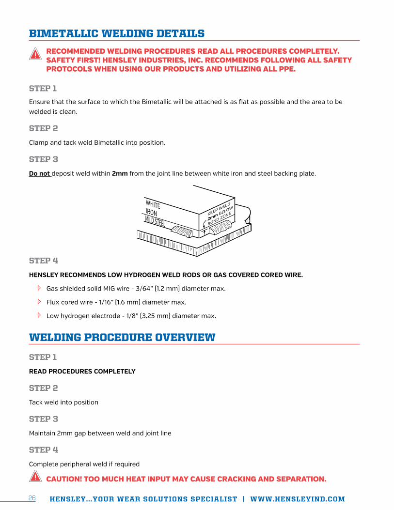
BIMETALLIC WELDING DETAILS
STEP 1
Ensure that the surface to which the Bimetallic will be attached is as flat as possible and the area to be welded is clean.
STEP 2
Clamp and tack weld Bimetallic into position.
STEP 3
Do not deposit weld within 2mm from the joint line between white iron and steel backing plate.
STEP 4
HENSLEY RECOMMENDS LOW HYDROGEN WELD RODS OR GAS COVERED CORED WIRE.
Gas shielded solid MIG wire - 3/64” (1.2 mm) diameter max.
Flux cored wire - 1/16” (1.6 mm) diameter max.
Low hydrogen electrode - 1/8” (3.25 mm) diameter max.
WELDING PROCEDURE OVERVIEW
STEP 1
READ PROCEDURES COMPLETELY
STEP 2
Tack weld into position
STEP 3
Maintain 2mm gap between weld and joint line
STEP 4
Complete peripheral weld if required
RECOMMENDED WELDING PROCEDURES READ ALL PROCEDURES COMPLETELY. SAFETY FIRST! HENSLEY INDUSTRIES, INC. RECOMMENDS FOLLOWING ALL SAFETY PROTOCOLS WHEN USING OUR PRODUCTS AND UTILIZING ALL PPE.
CAUTION! TOO MUCH HEAT INPUT MAY CAUSE CRACKING AND SEPARATION.

HENSLEY...YOUR WEAR SOLUTIONS SPECIALIST | WWW.HENSLEYIND.COM 2726
BOLT-ON END CAP INSTALLATION / REMOVAL INSTRUCTIONS
FILLER MATERIALS
Process AWS JIS NF DIN BS Shielding Gas
SMAW E7018 AWS A5.1
JIS Z3212 D5016
E515B12029(H) NF A 81 309
E51B10120 DIN 8556
E515B12029(H) BS 2926 N/A
GMAW ER 70S-6 AWS A5.18
JIS Z3312 YGW12
GS 2 NF A 81-311
SG2 DIN8559
A18 BS2901-1
100 CO2 90%Ar/8%CO2
GMAW E70C-6M AWS A5.18
JIS Z3313 YFW-A50DM N/A N/A N/A 92%Ar/8%CO2
90%Ar/10%CO2
FCAW E70T-5 AWS A5.20
JIS Z3313 YFW-C50DM
TGS 51 3.3 BH NF A 81-350
SG B1 CY4254 DIN
8559
T530 GBH BS7084
100% CO2 75%Ar/25%CO2
FCAW E71T-1 AWS A5.2
JIS Z3312 YFW-C50DR
TGS 51 3.3 BH NF A 81-350
SG B1 CY4254 DIN
8559
T530 GBH BS7084
100%CO2 75%Ar/25%CO2 90%Ar/10%CO2
PREHEAT AND INTERPASS TEMPERATURES
Material Thickness Minimum Preheat Temperature
Maximum Interpass Temperature
HENSLEY CASTINGS N/A 300ºF / 150ºC 450ºF / 230ºC
ASTM A514 (T1) THRU 1-1/2" / 38mm 125ºF / 50ºC 450ºF / 230ºC
BISALLOY 80 1-1/2" / 38mm THRU 2-1/2" / 63mm 175ºF / 80ºC 450ºF / 230ºC
WELDOX 100 OVER 2-1/2" / 63mm 250ºF / 120ºC 450ºF / 230ºC
400 BHN ABRASION RESISTANT STEEL - HARDOX 400
ALL THICKNESSES BETWEEN 1" / 25mm and 5" / 127mm 300ºF / 150ºC 450ºF / 230ºC
BEFORE PERFORMING THE WORK DESCRIBED, ALWAYS WEAR ALL REQUIRED SAFETY PPE AND FOLLOW ALL MINE SAFETY PROCEDURES.
HENSLEY...YOUR WEAR SOLUTIONS SPECIALIST | WWW.HENSLEYIND.COM 2928
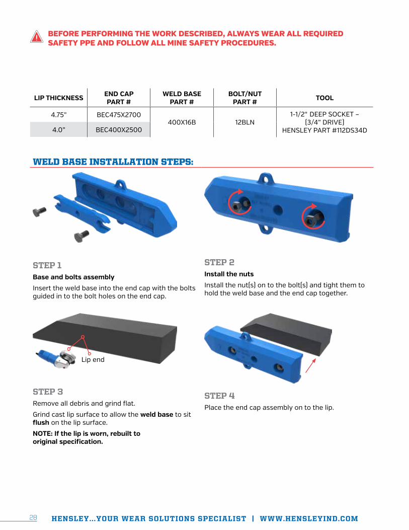
LIP THICKNESS END CAP PART #
WELD BASE PART #
BOLT/NUT PART # TOOL
4.75” BEC475X2700400X16B 12BLN
1-1/2" DEEP SOCKET – (3/4” DRIVE)
HENSLEY PART #112DS34D4.0” BEC400X2500
WELD BASE INSTALLATION STEPS:
STEP 1Base and bolts assembly
Insert the weld base into the end cap with the bolts guided in to the bolt holes on the end cap.
STEP 2Install the nuts
Install the nut(s) on to the bolt(s) and tight them to hold the weld base and the end cap together.
STEP 3Remove all debris and grind flat.
Grind cast lip surface to allow the weld base to sit flush on the lip surface.
NOTE: If the lip is worn, rebuilt to original specification.
STEP 4Place the end cap assembly on to the lip.
Lip end
BEFORE PERFORMING THE WORK DESCRIBED, ALWAYS WEAR ALL REQUIRED SAFETY PPE AND FOLLOW ALL MINE SAFETY PROCEDURES.
HENSLEY...YOUR WEAR SOLUTIONS SPECIALIST | WWW.HENSLEYIND.COM 2928
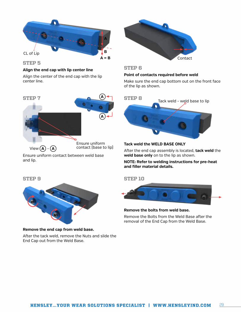
STEP 5Align the end cap with lip center line
Align the center of the end cap with the lip center line.
STEP 6Point of contacts required before weld
Make sure the end cap bottom out on the front face of the lip as shown.
STEP 7
Ensure uniform contact between weld base and lip.
STEP 8
Tack weld the WELD BASE ONLY
After the end cap assembly is located, tack weld the weld base only on to the lip as shown.
NOTE: Refer to welding instructions for pre-heat and filler material details.
STEP 9
Remove the end cap from weld base.
After the tack weld, remove the Nuts and slide the End Cap out from the Weld Base.
STEP 10
Remove the bolts from weld base.
Remove the Bolts from the Weld Base after the removal of the End Cap from the Weld Base.
A
BCL of LipA = B Contact
Tack weld - weld base to lip
Ensure uniform contact (base to lip)View A - A
A
A

HENSLEY...YOUR WEAR SOLUTIONS SPECIALIST | WWW.HENSLEYIND.COM 3130
STEP 11
Tack weld the weld base – (BOTH SIDES)
After removal of end cap assembly, tack weld the upper and lower portion of the weld base on to the lip.
NOTE: Refer to welding instructions for pre-heat and filler material details.
STEP 12
Plug weld the WELD BASE
After removal of end cap assembly, tack weld the upper and lower portion of the weld base on to the lip.
NOTE: Refer to welding instructions for pre-heat and filler material details.
STEP 13
Single bevel groove welding – (BOTH SIDES)
Apply a Single Bevel Groove Welding in the upper and lower recesses areas of the Weld Base.
NOTE: Refer to welding instructions for pre-heat and filler material details.
Tack weld - (both sides)

HENSLEY...YOUR WEAR SOLUTIONS SPECIALIST | WWW.HENSLEYIND.COM 3130
SECTION III: WELDING
TERMS AND
DEFINITIONS
HENSLEY...YOUR WEAR SOLUTIONS SPECIALIST | WWW.HENSLEYIND.COM 3332
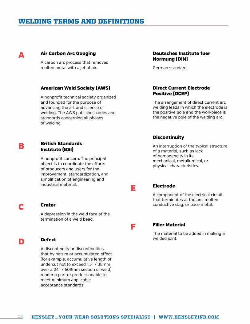
Air Carbon Arc Gouging
A carbon arc process that removes molten metal with a jet of air.
American Weld Society (AWS)
A nonprofit technical society organized and founded for the purpose of advancing the art and science of welding. The AWS publishes codes and standards concerning all phases of welding.
British Standards Institute (BSI)
A nonprofit concern. The principal object is to coordinate the efforts of producers and users for the improvement, standardization, and simplification of engineering and industrial material.
Crater
A depression in the weld face at the termination of a weld bead.
Defect
A discontinuity or discontinuities that by nature or accumulated effect (for example, accumulative length of undercut not to exceed 1.5" / 38mm over a 24" / 609mm section of weld) render a part or product unable to meet minimum applicable acceptance standards.
WELDING TERMS AND DEFINITIONS
Deutsches Institute fuer Normung (DIN)
German standard.
Direct Current Electrode Positive (DCEP)
The arrangement of direct current arc welding leads in which the electrode is the positive pole and the workpiece is the negative pole of the welding arc.
Discontinuity
An interruption of the typical structure of a material, such as lack of homogeneity in its mechanical, metallurgical, or physical characteristics.
Electrode
A component of the electrical circuit that terminates at the arc, molten conductive slag, or base metal.
Filler Material
The material to be added in making a welded joint.
A
B
C
D
E
F
HENSLEY...YOUR WEAR SOLUTIONS SPECIALIST | WWW.HENSLEYIND.COM 3332
Fillet Weld
A weld of approximately triangular cross section joining two surfaces approximately at right angles to each other in a lap joint, T-joint, or corner joint.
Flux Cored Arc Welding (FCAW)
An arc welding process that uses an arc between a continuous filler metal electrode and the weld pool. The process is used with shielding gas from a flux contained within the tubular wire electrode, with or without additional shielding from an externally supplied gas and without the application of pressure.
Francaise de Normalisation (NF)
French standard.
Gas Metal Arc Welding (GMAW)
An arc welding process that uses an arc between a continuous filler metal electrode and the weld pool. The process is used with shielding from an externally supplied gas and without the application of pressure.
Japanese Industrial Standards (JIS)
The Japanese Standards Association publishes standards, including metals, welding filler materials, etc.
Layer
A stratum of weld metal consisting of one or more weld beads.
Overlap
The protrusion of weld metal beyond the weld toe or weld root.
Porosity
A cavity-type discontinuity or defect formed by gas entrapment during solidification.
Preheat
The application of heat to the work piece prior to welding cutting or gouging.
Root
The point, shown in cross section, at which the weld metal extends furthest into a joint and intersects the base metal.
Run-off Weld Tab
Additional material that extends beyond the end of the joint, on which the weld is terminated.
G
J
L
O
P
R

HENSLEY...YOUR WEAR SOLUTIONS SPECIALIST | WWW.HENSLEYIND.COM 3534
Shielded Metal Arc Welding (SMAW)
An arc welding process with an arc between a covered electrode and the weld pool. The process is used with shielding from the decomposition of the electrode covering, without the application of pressure, and with filler metal from the electrode.
Shielding Gas
Protective gas used to prevent or reduce atmospheric contamination of a weld, especially by oxygen and nitrogen.
Starter Weld Tab
Additional material that extends beyond the beginning of the joint, on which the weld is started.
Stringer Bead
A type of bead made without appreciable weaving motion.
Tack Weld
A weld made to hold the parts of a weldment in proper alignment until the final welds are made.
W
T
US Undercut
A groove melted into the base metal adjacent to the weld toe or root and left unfilled by weld metal.
Weld Groove
A channel in the surface of a work piece or an opening between two joint members that provides space to contain weld.
Weld Toe
The junction of the weld face and the base metal.
Welding Sequence
The order of making welds in a weldment.

HENSLEY...YOUR WEAR SOLUTIONS SPECIALIST | WWW.HENSLEYIND.COM 3534

Since 1947, Hensley Industries, Inc. has dedicated itself to providing superior products and service across the globe.Hensley’s continuous commitment to safety, quality, reliability and our customers enables us to help those in the field every day.
Safety First! Hensley Industries, Inc. recommends following all safety
protocols when using our products and utilizing all PPE.
©2018 Hensley Industries, Inc. This publication is protected under the copyright
laws of the United States. Unauthorized duplication or distribution is prohibited.
HENSLEY INDUSTRIES, INC. 2108 Joe Field Road Dallas, Texas 75229 USA
CUSTOMER SERVICE USA/Canada (888) 406-6262 International +1 (972) 406-6262
www.HENSLEYIND.com
WG-01-032217