Embed Size (px)
Citation preview

UG:015 vicorpower.com Applications Engineering: 800 927.9474 Page 1
Introduction
The 2361 and 6123 Converter housed in a Package (ChiP) Bus Converter Module (BCM) evaluation board described in this document is designed to be used with the BCM family of isolated, DC-DC Bus converters. The Evaluation board is used for both the analog control, and digital control BCM products.
The focus of this document is to assist the user in evaluating the analog control version of the BCM family.
The BCM evaluation board can be configured for various enabling and fault monitoring schemes, as well as to exercise various loading conditions depending on the application requirements. The evaluation board can be used to evaluate BCMs in either a stand-alone configuration, or as an array of modules.
It is important to remember the fast response of BCMs can readily show the limitations of the source, load, and associated wiring connected to the evaluation board. Care should be exercised to minimize the stray source and load impedance in order to fully exercise the BCM.
Refer to the appropriate data sheet for performance and operating limits. Data sheets are available at http://www.vicorpower.com/dc-dc-converters-board-mount/bus-converter-module.
Enable Options:1. Apply input voltage greater than the BCM under voltage lockout. (Default)2. On-board mechanical switch3. External control using available test point
Fault Monitor Options:1. On-board LED: the VAUX pin drives a visible LED for visual feedback on the BCM status such as enabled or fault condition.
Analog 2361 and 6123 ChiP BCM® Bus Converter Evaluation Board User Guide
USER GUIDE | UG:015
Written by: Peter Makrum Applications EngineerApril 2015
Contents Page
Introduction 1
Contents 2
Features 3
Board Description 3
General Components 3
Test Points Description 6
Schematic & Assembly 7
Drawings
Bill of Materials 11
Recommended Test 12Equipment
Basic Connection 13
Board Operation 13Details
Thermal Consideration 13
Paralleling 14

UG:015 vicorpower.com Applications Engineering: 800 927.9474 Page 2
IMPORTANT NOTICE:
Hazardous voltages are present on the HV BCM Evaluation Board under power.
PERSONAL CONTACT WITH LINE VOLTAGE MAY RESULT IN SEVERE INJURY, DISABILITY, OR DEATH. IMPROPER OR UNSAFE HANDLING OF THIS BOARD MAY RESULT IN SERIOUS INJURY OR DEATH.
Read the precautions below entirely BEFORE using the BCM Evaluation Board. Do not operate the evaluation board unless appropriate bench safety precautions are in place to guarantee safety.
The list below is not comprehensive and is not a substitute for common sense and good practice.
n During operation, the power devices and surrounding structures can be operated safely at high temperatures.
n Remove power and use caution when connecting and disconnecting test probes and interface lines to avoid inadvertent short circuits and contact with hot surfaces.
n Never use a jumper in place of the fuse.
n When testing electronic products always use approved safety glasses. Follow good laboratory practice and procedures.
n Avoid creating ground loops when making measurements of the isolated input or output voltage.
n Care should be taken to protect the user from accidental contact when under power.
n Care should be taken to avoid reversing polarities if connecting to the opposite (solder) side of the board.
n The product evaluation boards described in this document are designed for general laboratory evaluation, and are not suitable for installation in end user equipment.
n Refer to the specific BCM module data sheet for electrical, thermal, and mechanical product details.
These boards provide a convenient way to evaluate/demonstrate the performance of Vicor’s BCM products. Kelvin connections are provided for accurate voltage measure-ments on power nodes. Sockets are provided to permit quick installation and changing of bulk filtering capacitors. The evaluation board also provides lugs for Input / output connections, test points and sockets for easy connection to standard test equipment, and a high performance air cooled heatsink assembly.
Contents
The evaluation board arrives with the following contents:
n 1 x BCM evaluation boardn 1 x Top heatsink pre-installed as well as a bottom of the ChiP heatsink when applicablen 1 x hardware kit: n 1 x through-hole aluminum-electrolytic output capacitor (C121) n 3 x Connector Receptacle 8 position n 2 x Connector socket 2 position n 5 x size 10 screws, lugs and washers

UG:015 vicorpower.com Applications Engineering: 800 927.9474 Page 3
Features
The BCM evaluation board has the following features:
1. Input and output lugs for source and load connections
2. Appropriately rated input fuse
3. Input Aluminum Electrolytic capacitor for additional source decoupling
4. Basic output filtering footprint, including sockets to add through-hole output Aluminum Electrolytic capacitors
5. Toggle switch for enabling and disabling the BCM via the enable (EN) pin
6. Oscilloscope probe jack for accurate, high frequency output voltage measurements
7. Connectors for BCM signal pins (TM, EN, and VAUX) and temperature monitor filtered signal
8. Kelvin voltage test points for all power pins
9. Top and bottom heatsink assembly for the BCM where applicable
Board Description
The following section provides a detailed description of the evaluation board components, test points and sockets.
General Components
1. BCM (PS01)2. Input lugs: Sized for #10 hardware. Use for making connection to the input source. This board does not contain reverse polarity protection. Check for proper polarity before applying the power. It is important to remember that noise from the source and voltage drops, will appear at the output of the bus converter multiplied by transformation ratio (K). The K factor is the ratio of the output voltage to the input voltage (VOUT / VIN).
3. Input fuse (F101 & F102): Appropriately rated for the BCM model installed on the board. The fuse is not meant to protect the module.
4. Input filtering: Aluminum Electrolytic input capacitor (C101).
5. Enable / Disable switch (SW101): When actuator is in top position towards “ON” text on the board, the (EN) pin will be open and the BCM will be enabled. When actuator is in bottom position towards “OFF” text on the board, the (EN) pin will be connected to (-IN) pin and the BCM will be disabled. When switch (SW101) is “ON”, an external voltage source can control the EN pin state.
6. Signal connector (J102): provides access to the bus converter signal pins (TM, EN, and VAUX) as well as (TM_DC) externally filtered signal. All signal pins are reference to the primary non-isolated voltage return (-IN) pin.

UG:015 vicorpower.com Applications Engineering: 800 927.9474 Page 4
Figure 1.
BCM Signal connector (J102)
–VIN –VIN –VIN –VIN
TM_PWM ENVAUXTM_DC
2 4 6 8
1 3 5 7
n Temperature Monitor (TM): The BCM (TM) pin outputs a 250 kHz PWM signal. A 1 kΩ and a 10 nF is the recommended low pass filtering solution. (TM_PWM) and filtered (TM_DC) are both accessible on (J102) connector header. (TM_DC) measures 1.27 V for a 27°C internal temperature corresponding to a (TM_PWM) duty cycle of 38.48%.
n Enable Control (EN): Connecting the BCM (EN) pin to (–IN) will disable the module. (SW101) can be used to turn off the power train and disable the module. The (EN) pin is internally pulled up. This connector can be used to bus the (EN) pin in an array allowing array synchronous startup.
n Auxiliary Voltage Source (VAUX): The BCM (VAUX) can be used as a fault flag it is internally driven low during a fault condition. The (VAUX) pin can also be used as a ready to process full power flag. A 2 ms delay from power train active is introduced on this pin signaling the end of soft-start. During normal operation this pin can be used as an auxiliary supply up to 4 mA max load.
7. Output lugs: Sized for #10 hardware. Use these lugs to connect the output directly to the load.
8. Output oscilloscope probe Jack (J101): Used for making accurate scope measurements of the output voltage (e.g. ripple). The jack is directly compatible with many common passive voltage probes models. Remove the grounding lead and insulating barrel of the probe and insert the probe tip and barrel directly into the jack, ensuring that the probe tip sits in the center socket of the jack. To avoid the risk of an inadvertent short circuit, do not attempt to install while power is applied. This Johnson Jack is kelvin connected to the module output pins. The effect of the output capacitors will not be noticeable.
9. Output filter: 10x output ceramic capacitors 1206 footprint provision (C103, C104, C113, C114, C115, C116, C117, C118, C119, and C120). In addition to socket (C121) that can be used for easy installation of an Aluminum Electrolytic output capacitor included with in hardware kit of the evaluation board.
10. Isolation barrier: R106, R107, R108 each are a 2010 package. The footprint can be used to provide a convenient means to short the isolation barrier or provided an additional AC path using capacitors.

UG:015 vicorpower.com Applications Engineering: 800 927.9474 Page 5
Figure 2.
2361 BCM evaluation board photo, top side

UG:015 vicorpower.com Applications Engineering: 800 927.9474 Page 6
Test Points Description
Test nodes are labeled and include an SMT test point for attaching miniature probes, clips or hooks.
Name Description
+VIN, –VIN
Provide measurement test points for the input voltage of
the BCM module. Test points are Kelvin connected to the
module input pins.
EN Used to measure the BCM EN pin relative to –VIN.
TM_DCUsed to measure the filtered BCM TM signal using a
recommended low pass filter relative to –VIN.
TM_PWMUsed to measure the BCM TM pin which is a pulse width
modulated output signal relative to –VIN.
VAUXUsed to measure the BCM VAUX pin output signal
relative to –VIN.
Name Description
+VOUT, –VOUT
Provide measurement test points for the output voltage of
the BCM module. Test points are Kelvin connected to the
module output pins.
Table 1.
Primary referenced test point descriptions
Table 2.
Secondary referenced test point descriptions
UG:015 vicorpower.com Applications Engineering: 800 927.9474 Page 7
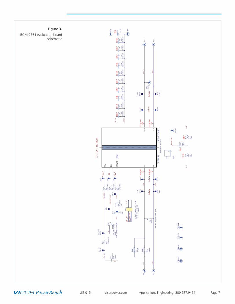
Figure 3.
BCM 2361 evaluation board schematic
TP10
1
TP10
2
TP10
5
TP10
6
+IN
-IN
TP10
3TP
107
TP10
8
+OU
T
-OU
T
iSE
CO
ND
AR
Y
iSE
CO
ND
AR
Y
iPR
IMA
RY
iPR
IMA
RY
TP10
4
TP10
9
3329
2J1
01
0603
1546
2-10
01
1KR10
1
2940
0-10
306
030.
01uF
C10
2
-VIN
+IN
HSG
ND
CH
ASS
IS_G
ND
GN
D
EMI 1
HS0
1
-VIN
+VIN
-VO
UT
+VO
UT
+OU
T+O
UT
-IN+IN
-OU
T
CL
DA
AD
PRIM
AR
YSE
CO
ND
AR
YIS
OLA
TIO
N B
OU
ND
RY
PS01
SER
-OU
T
-VIN
-VIN
0603
1469
5-75
0075
0
R10
2
4005
808
05
D10
1
LED
TP11
1
BC
M O
N/O
FF C
ON
TRO
L
0603
1469
5-00
R0
R10
4
TP11
0
4053
8
231S
W10
1
SW_G
T11M
SAB
E
-VIN
EN
SER
-IN
TM
FID
101
FID
102
0603
1546
2-0R
00
R10
3
0603
1546
2-0R
00
R10
5
Kel
vin
Kel
vin
Kel
vin
Kel
vin
+VO
UT
-VO
UT
-VIN
+VIN
3079
9C
101
CA
P A
LEL
10uF
20%
450
V R
AD
4100
9
851
673
42J1
02
A33
079-
ND
/ 5
-1031
66-2
CO
NN
HEA
DER
R/A
.10
0 8PO
S
TM_P
WM
EN_N
ON
-CO
M
VA
UX
2361
LV
/ H
V B
CM
TM_D
C
-VIN
TM_D
CTM
_PW
M
EN_N
ON
-CO
MV
AU
X
TP11
2EN
2518
5-10
512
061u
FC
119
2518
5-10
512
061u
FC
120
+VO
UT
2518
5-10
512
061u
FC
117
2518
5-10
512
061u
FC
118
2518
5-10
512
061u
FC
115
2518
5-10
512
061u
FC
116
2518
5-10
512
061u
FC
114
-VO
UT
3079
9
C12
1
H01 H02
FID
103
FID
104
3768
8
40AF1
02
FUSE
1992
45AF1
01
TP11
3TM
_DC
TP11
4TM
_PW
M
2010
DN
PD
NP
R10
6
-VIN
-VO
UT
DN
PD
NP
DN
P
DN
PD
NP
DN
PD
NP
DN
PD
NP
DN
PD
NP
DN
PD
NP
DN
P
2010
DN
PD
NP
R10
7
2010
DN
PD
NP
R10
8
2518
5-10
512
061u
FC
103
2518
5-10
512
061u
FC
104
2518
5-10
512
061u
FC
113
TP11
5EN VA
UX

UG:015 vicorpower.com Applications Engineering: 800 927.9474 Page 8
Figure 4.
BCM 6123 evaluation board schematic
TP10
1
TP10
2
TP10
5
TP10
6
+IN
-IN
TP10
3TP
107
TP10
8
+OU
T
-OU
T
iSE
CO
ND
AR
Y
iSE
CO
ND
AR
Y
iPR
IMA
RY
iPR
IMA
RY
TP10
4
TP10
9
3329
2J1
01
0603
1546
2-10
01
1KR10
1
2940
0-10
306
030.
01uF
C10
2
-VIN
+IN
HSG
ND
CH
ASS
IS_G
ND
GN
D
EMI 1
HS0
1
-VIN
+VIN
-VO
UT
+VO
UT
SER
-OU
T
-VIN
-VIN
0603
1469
5-75
0075
0
R10
2
4005
808
05
D10
1
LED
TP11
1
BC
M O
N/O
FF C
ON
TRO
L
0603
1469
5-00
R0
R10
4
TP11
0
4053
8
231S
W10
1
SW_G
T11M
SAB
E
-VIN
EN
SER
-IN
FID
101
FID
102
0603
1546
2-0R
00
R10
3
0603
1546
2-0R
00
R10
5
Kel
vin
Kel
vin
Kel
vin
Kel
vin
+VO
UT
-VO
UT
-VIN
+VIN
3079
9C
101
CA
P A
LEL
10uF
20%
450
V R
AD
4100
9
851
673
42J1
02
A33
079-
ND
/ 5
-1031
66-2
CO
NN
HEA
DER
R/A
.10
0 8PO
S
TM_P
WM
EN_N
ON
-CO
M
VA
UX
6123
LV
/ H
V I
sola
ted
BC
M
TM_D
C
-VIN
TM_D
CTM
_PW
M
EN_N
ON
-CO
MV
AU
X
TP11
2EN
2518
5-10
512
061u
FC
119
2518
5-10
512
061u
FC
120
+VO
UT
2518
5-10
512
061u
FC
117
2518
5-10
512
061u
FC
118
2518
5-10
512
061u
FC
115
2518
5-10
512
061u
FC
116
2518
5-10
512
061u
FC
114
-VO
UT
3079
9
C12
1
H01 H02
FID
103
FID
104
3768
8
40AF1
02
FUSE
1992
45AF1
01
TP11
3TM
_DC
TP11
4TM
_PW
M
2010
DN
PD
NP
R10
6
-VIN
-VO
UT
DN
PD
NP
DN
P
DN
PD
NP
DN
PD
NP
DN
PD
NP
DN
PD
NP
DN
PD
NP
DN
P
2010
DN
PD
NP
R10
7
2010
DN
PD
NP
R10
8
2518
5-10
512
061u
FC
103
2518
5-10
512
061u
FC
104
2518
5-10
512
061u
FC
113
TP11
5
+OU
T+O
UT
-IN+IN
-OU
T
CL
DA
AD
PRIM
AR
YSE
CO
ND
AR
YIS
OLA
TIO
N B
OU
ND
RY61
23PS
01
* TM
E
N
V
AU
X

UG:015 vicorpower.com Applications Engineering: 800 927.9474 Page 9
Figure 5.
BCM 2361 evaluation board
Figure 6.
BCM 2361 evaluation board

UG:015 vicorpower.com Applications Engineering: 800 927.9474 Page 10
Figure 7.
BCM 6123 evaluation board
Figure 8.
BCM 6123 evaluation board

UG:015 vicorpower.com Applications Engineering: 800 927.9474 Page 11
Bill of Materials
Following table describes the design specific components of all 2361 and 6123 BCM evaluation board.
Reference
DesignatorDescription Manufacturer
Manufacturer
Part Number
C101 CAP ALEL 10 µF 20% 450 V RAD United Chemi-Con EKXG451ELL100MK20S
C102 CAP X7R .010 µF 10% 50 V 0603Murata
ManufacturingGRM188R71H103KA01D
D101 DLED RED 0805 Rohm SML-211UTT86
F101Design specific - See Table 4
F102
J101JACK VERTICAL MECH THRU
HOLETektronix 131-5031-00
J102CONN HEADER R/A .100 8POS
30AUTE Connectivity Ltd 5-103166-2
HS01 Design specific - See Table 4
PCB Part Number Design specific - See Table 4
R103, R104, R105 RES 0 OHM JUMPER 1 A 0603 KOA Speer Electronics RK73Z1JTTD
R102 RES 750 OHM 1/10W 5% 0603 KOA Speer Electronics RK73B1JTTD751J
R101 RES 1K OHM 1/10W 1% 0603 KOA Speer Electronics RK73H1JTTD1001F
SW101 SW Horizontal SPDT 1 POS SMD C&K Components GT11MSABETR
Table 3.
BCM Evaluation board components common
to all boards

UG:015 vicorpower.com Applications Engineering: 800 927.9474 Page 12
Reference
DesignatorDescription Manufacturer
Manufacturer
Part Number
Evaluation board numbers: BCD54AP135T1K8AC0; BCD54AP090T1K4AC0
PS01 LV BCM - 2361 Vicor CorporationBCM54AP135T1K8AC0;
BCM54AP090T1K4AC0
PCB Part Number 2361 BCM Evaluation Board Vicor Corporation 42030
F102FUSE 40A 60VAC FAST 4.5X12.5
SMDLittelfuse 0456040.DR
HS01 BOM HEATSINK, TOP, 2361 CHIP Vicor Corporation 41248
Evaluation board numbers: BCD384P120T1K5AC0; BCD384P120T800AC0; BCD384P120T1K5ACR;
BCD384P120T800ACR
PS01 HV BCM - 2361 Vicor Corporation
BCM384P120T1K5AC0;
BCM384P120T800AC0;
BCM384P120T1K5ACR;
BCM384P120T800ACR
PCB Part Number 2361 BCM Evaluation Board Vicor Corporation 42030
F101 FUSE PC-TRON PCI 5A Cooper Industries PCI-5-R
HS01 BOM HEATSINK, TOP, 2361 CHIP Vicor Corporation 41248
Evaluation board numbers: BCD400P500T1K8A30; BCD380P475T1K2A30; BCD380P475T800A30;
BCD400P500T1K8A3R; BCD380P475T1K2A3R; BCD380P475T800A3R
PS01 HV BCM - 6123 Vicor Corporation
BCM400P500T1K8A30;
BCM380P475T1K2A30;
BCM380P475T800A30;
BCM400P500T1K8A3R;
BCM380P475T1K2A3R;
BCM380P475T800A3R
PCB Part Number 6123 BCM Evaluation Board Vicor Corporation 42143
F101 FUSE PC-TRON PCI 5A Cooper Industries PCI-5-R
HS01BOM ASSY 6123 DUAL HTSNK
NO TIM FOR 11 MMVicor Corporation 40528
Recommended Test Equipment
The following is a list of recommended test equipment.
1. Safety glasses
2. DC power supply: Refer to the specific BCM model datasheet to ensure the supply has sufficient power and current capability
3. Electronic load: Refer to the specific BCM model datasheet to ensure the load has sufficient power handling and current capability for testing
4. Cooling fan
5. Digital multi-meters (DMMs)
6. Oscilloscope and probes
7. Interconnect wires, cables and fastening hardware
Table 4.
BOM additions, components which are BCM model specific
UG:015 vicorpower.com Applications Engineering: 800 927.9474 Page 13
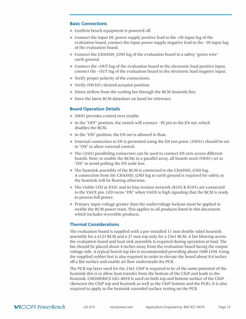
Basic Connections
n Confirm bench equipment is powered off.
n Connect the input DC power supply positive lead to the +IN input lug of the evaluation board, connect the input power supply negative lead to the –IN input lug of the evaluation board.
n Connect the CHASSIS_GND lug of the evaluation board to a safety “green wire” earth ground.
n Connect the +OUT lug of the evaluation board to the electronic load positive input, connect the –OUT lug of the evaluation board to the electronic load negative input.
n Verify proper polarity of the connections.
n Verify (SW101) desired actuator position.
n Direct airflow from the cooling fan through the BCM heatsink fins.
n Have the latest BCM datasheet on hand for reference.
Board Operation Details
n SW01 provides control over enable.
n In the “OFF” position, the switch will connect –IN pin to the EN net, which disables the BCM.
n In the “ON” position, the EN net is allowed to float.
n External connection to EN is permitted using the EN test point. (SW01) should be set to “ON” to allow external control.
n The (J102) paralleling connectors can be used to connect EN nets across different boards. Note: to enable the BCMs in a parallel array, all boards need (SW01) set to “ON” to avoid pulling the EN node low.
n The heatsink assembly of the BCM is connected to the CHASSIS_GND lug. A connection from the CHASSIS_GND lug to earth ground is required for safety as the heatsink will be floating otherwise.
n The visible LED at D101 and its bias resistor network (R102 & R105) are connected to the VAUX pin. LED turns “ON” when VAUX is high signaling that the BCM is ready to process full power.
n Primary input voltage greater than the undervoltage lockout must be applied to enable the BCM power train. This applies to all products listed in this document which includes reversible products.
Thermal Considerations
The evaluation board is supplied with a pre-installed 11 mm double sided heatsink assembly for a 6123 BCM and a 27 mm top only for a 2361 BCM. A fan blowing across the evaluation board and heat sink assembly is required during operation at load. The fan should be placed about 4 inches away from the evaluation board facing the output voltage side. A typical bench top fan is recommended providing about 1000 LFM. Using the supplied rubber feet is also required in order to elevate the board about 0.4 inches off a flat surface and enable air flow underneath the PCB.
The PCB top layer used for the 2361 ChiP is required to be of the same potential of the heatsink this is to allow heat transfer from the bottom of the ChiP and leads to the heatsink. CHOMERICS GEL-8010 is used on both top and bottom surface of the ChiP. (Between the ChiP top and heatsink as well as the ChiP bottom and the PCB). It is also required to apply to the heatsink extended surface resting on the PCB.

The Power Behind Performance
Rev 1.3 07/2015 vicorpower.com Applications Engineering: 800 927.9474 Page 14
Paralleling
The paralleling and sharing performance of multiple BCMs can be easily demonstrated by stacking multiple evaluation boards and interconnecting the inputs and outputs with standoffs to create a parallel array. Each BCM in an array operates in the same way as it does as a stand-alone unit. With equal impedance, the load is effectively shared across multiple BCMs. Mismatches in this case are modest, and are further canceled by an effective negative voltage vs. temperature coefficient.
The following connections and settings should be used for an array of BCM evaluation boards:
n All BCMs in a parallel array must be the same model.
n The boards should be physically stacked using metal standoffs at the +IN & –IN lugs, the +OUT & –OUT lugs, and the CHASSIS_GND lug. This also connects these nodes electrically so that a single source, single load, and earth ground connection can be made to the system.
n The +IN lugs are required to be connected together for an array of BCMs.
n Standoffs must be sufficient in length to avoid contact between boards, and to permit airflow to all BCMs in the system.
n If coordinated enable control then the paralleling connectors (J102) can be used to easily interconnect the EN pin across boards.
n The paralleling connector receptacle (J102) is provided to daisy chain EN signal and –VIN. The will accept a wire size range 26 - 22 AWG, 0.12 - 0.3 mm2 wires.
The paralleling and current sharing capability of the devices can be demonstrated by stacking multiple evaluation board and interconnecting the inputs and outputs with standoffs of sufficient current rating to create a parallel array. If synchronous startup is desired, connect EN pin 5 and –VIN pin 6 in (J102) using a twisted pair to all respective pins in different paralleled units.
Figure 9.
BCM evaluation boards stacked to form a high power parallel array, using common -IN and
the paralleling connectors. Paralleling of
BCM evaluation board.