Embed Size (px)
Citation preview
fITIC FILE COP"I (Naval Research LaboratoryWashingtM. DC 203755000"
NRL Memorandum Report 6123
Revised Impact Dynamic Design-Analysis Method(RIDDAM)
0') R.L. BORT
Structural Integrity BranchMaterial Science and Technology Division
o%Yan
February 10, 1988
0
<:%V *'
0
Approved for public release, distribution unlimited
68 ,

SECURITY CLASSIFICATION OF THIS PAGESForm Approved
REPORT DOCUMENTATION PAGE IOMBNo 0704-088
la REPORT SECURITY CLASSIFICATION 1b RESTRICTIVE MARKANGS
UNCLASSIFIED2a. SECURITY CLASSIFICATION AUTHORITY 3 DISTRIBUTIONY AVAILABILITY OF REPORT
2b DECLASSIFICATION/DOWNGRADING SCHEDULE Approved for public release; distributionunlimited.
4. PERFORMING ORGANIZATION REPORT NUMBER(S) S MONITORING ORGANIZATION REPORT NUMBER(S)
NRL Memorandum Report 6123
6a. NAME OF PERFORMING ORGANIZATION 6b OFFICE SYMBOL 7a NAME OF MONITORING ORGANIZATION(If applicable)
Naval Research Laboratory Code 63376c. ADDRESS (City, State, and ZIPCode) 7b ADDRESS (City, State, and ZIP Code)
Washington, DC 20375-5000
8a. NAME OF FUNDING/SPONSORING 8b OFFICE SYMBOL 9 PROCUREMENT INSTRUMENT IDENTIFICATION NUMBERORGANIZATION (If applicable)
Naval Sea Systems Command Code 55X11
8c. ADDRESS (City. State, and ZIP Code) 10 SOURCE OF FUNDING NUMBERSPROGRAM PROJECT TASK WORK uNIT
Washington, DC 20362-5101 ELEMENT NO NO NO ACCESSION NO
63561N S0971 DN980-16011 TITLE (Irclude Security Classification)
Revised Impact Dynamic Design-Analysis Method (RIDDAM)
12 PERSONAL AUTHOR(S)
Bort, R.L.13a TYPE OF REPORT 13b TIME COVERED 14 DATE OF REPORT (Year, Month, Day) 15 PAGE CO(J N
InterimFROM TO 9 7 1988 February 10 8716 SUPPLEMENTARY NOTATION
17 COSATI CODES 18 SUBJECT TERMS (Continue on reverse if necessary and identify by block number)
FIELD GROUP SUB-GROUP Torpedo impact ,-'
Impact dynamic design-analysis method (IDDAM)
19 ABSTRACT (Continue on reverse if necessary and identify by block number)
- Theory and examples are shown for a feasible method of estimating responses of equipment to animpact of an exercise torpedo against the hull of a submarine. The equipment is modeled as a linear andelastic system whose normal modes of vibration respond in accordance with their weight and frequency. Asimple method is used for determining the effective weight of a normal mode. The method is applicable tomultiple modes and independent motions of multiple supports. '1
20 DISTRIBUTION, AVAILABILITY OF ABSTRAC T 2 Aj3"TRACT ' 11- '
(A b A
$0 UNCLASSIFIED/JNLIMI TED []l SAME AS -PI C1 )Ttr" ,j FQ, (NC,\SSIFTED22a NAME OF RESPONI'SBLE NDIVIDtJAL ,'.;'h 'F! (fwtud( 4 4 l~r( ' - ' 1 ,,f '' '- " """;
Robert L. Bort (202) 767-277 Co d 1 337
;D Form 1473. JUN 86 0''o,ous -,nr,,rS i. ohsolr ... " . ,
S ' r~ i _ - 0 i- ) , * , 1
EXAMPLES .................................................................... 32
A Textbook Example .............................................- 32An Example with Cross-Axis Response ....................... 39An Example with Rotational Inertia .......................... 43A Real Example ..................................................... 48
APPENDIX A - A Short Introduction to Matrix Algebra ...... 59
APPENDIX B - A Computer Program for RIDDAM ............... 65
Acce, 3tofl For
NTIS CRA&IDTIC TAR
utiainiuncedJust4t ioation.------a
By--
Diiv
ReI
lip
.1~ - .(VG
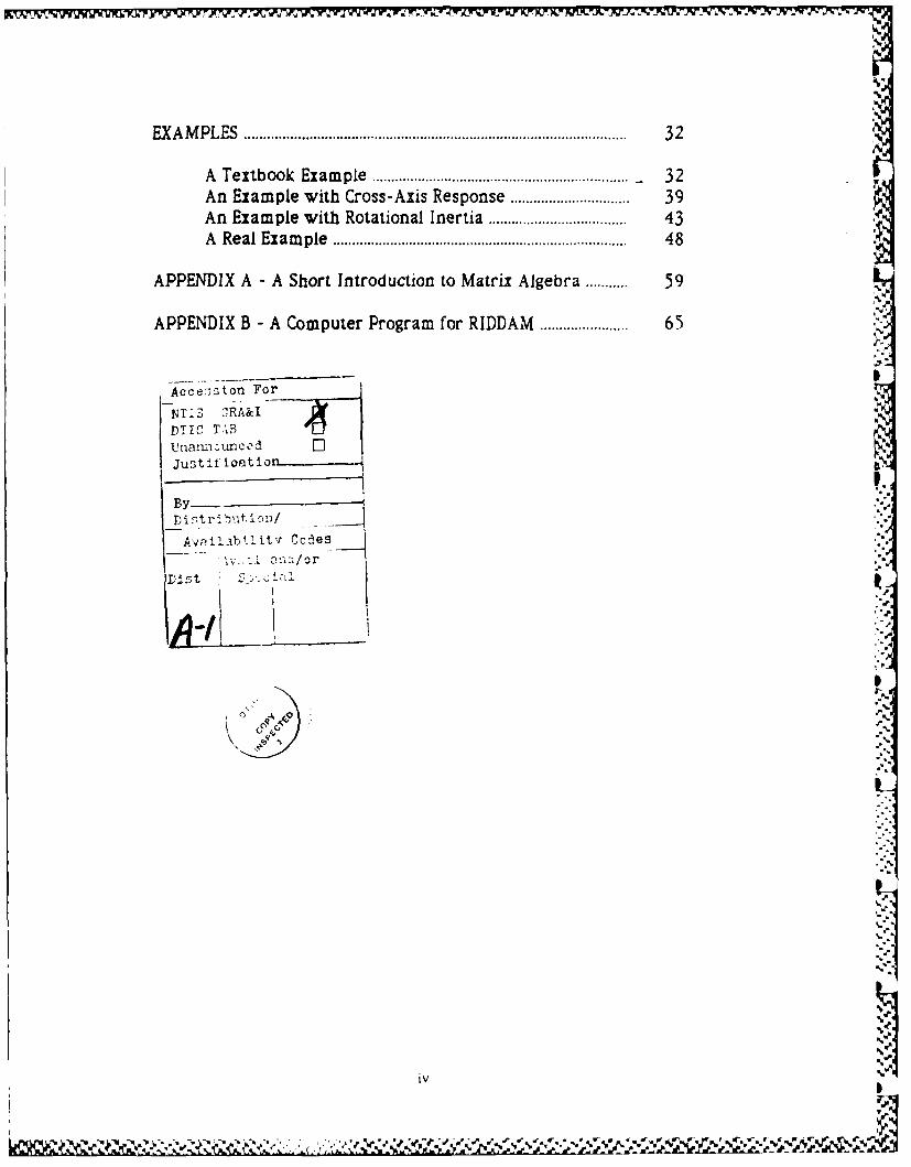
CONTENTS
INTRODUCTION ............................................................................................... I
Background ......................................................................................... 1Revision of the IDDAM ..................................................................... 2Procedure ............................................................................................. 4Outline ................................................................................................... 5
THEORY ............................................................................................................... 6
M athem atical M odel ........................................................................ 6Norm al M odes of Vibration ......................................................... 7M odal M ass ........................................................................................ 9Inputs ................................................................................................... 13Accelerations, Forces. Stresses, and Deformations ............ 14W arpage ............................................................................................. 15Sum m ary ............................................................................................. 16
APPLICATION ................................................................................................ 17
Units .................................................................................................... 17Scaling of Modeshapes ........................ 18Suppression of Tim e Histories .................................................. 20Time Histories and Combination Rules .............. 21Combining Peak Responses from Different Supports ..... 22Combining Peak Responses for Modes of Different
Frequencies ........................................................................ 22Selection Rules for the NRL Sum .................. 24Sum m ary ......................................................................................... . 25
SPECIAL PROBLEM S .................................................................................. 27
Design Spectra ............................................................................... 27Repeated Frequencies ................................................................ 27.Closely-Spaced M odes ................................................................ 28Rules of Thum b ............................................................................ 31
" °" % "- "..',, . ""°" o° 4 ,.) ".-= ,.' " °w" 4" o" ,.+'.e" .".- ",. =, " . ".= , , °- "- "' -= " " . ,, "m -4"" . " ",."" • •
" " , ", ",, ,, .€. " . . . .
REVISED IMPACT DYNAMIC DESIGN-ANALYSIS METHOD (RIDDAM)
INTRODUCTION
BACKGROUND
A par'ticular dynamic design-analysis method. DDAM, has beenapplied to selected equipment on Navy ships since 1960. The DDAM isbased on measurements of the responses of shipboard equipment tocontrolled tests against ships with underwater explosions.Measurements from a variety of ships showed that the responses ofequipment to the shock from an underwater-explosion attack couldbe approximated fairly well by considering only the location of theequipment on the ship, the weight of the equipment, and its naturalfrequency of vibration. Collected measurements were fitted to simpleformulas depending on location, weighl, and frequency that could beused to check the ability of equipment to resist shocks fromunderwater explosions
The DDAM can be looked at in modern terms as an approximatemethod of conducting a substructure analysis of a complex dynamicsystem. In the DDAM all of the effort in the analysis is directed,oward one particular substructure, representing the equipment ofinterest. The main structure consisting of all the rest of the ship, istaken as a standard structure whose properties do not need to bespecially determined The experimental measurements of the shockthat the ship can transmit to equipmenm of different weights andtrequencies during an under%% ater-explosion attack take the place ofan analysis of the ship s structure
The effort of the analyst in applying the DDAM is limited todetermining the frequencies and weights associated with oneparticular item of equipment The formulas from the DDAM thenprovide the analyst immediatelv with the responses that would beexpected at each weight and frequencv if the equipment weremounted at a particular location on a standard ship during an attackagainst the ship with an underwater explosion The analyst performs,
Manuscnr approved November 13, 1987.
a
in effect, a substructure analysis without having to analyze the mainstructure or consider location of the equipment beyond the broadcategories given in the formulas.
IDDAM
Calculations for the DDAM are based on the assumption that theshock from an underwater explosion produces a translation of the shipin a single direction, with all of the supports for the equipment
moving identically. This is generally a good approximation forcompact equipment or for explosions that take place in the watersome distance from the ship.
An extension of the DDAM, referred to as IDDAM (ImpactDDAM) was developed in 1977 in response to a request for a dynamicdesign-analysis method that could be applied to the case of the impactof exercise (nonexploding) torpedoes against the hull of a submarine.Here th shock applied to the several supports for a particular item ofequipment attached to the hull could vary greatly, from a severeshock to a support directly in way of the impact to shocks of smallerand smaller severity with increase in distance from the point ofimpact.
Determining the response of a structure to independent motionsof multiple supports involved only a minor elaboration of DDAM.However, the weight of the structure had to be distributed among theseparate supports in a self-consistent fashion in order to allow 'hesimple formulas involving weight and frequency to be applied. Whenall of the supports move identically, as in DDAM, the full weight reactsagainst the common motion, but when the motions are different theweight appears as a combination of direct and cross terms among thesupports, adding appreciably to the complexity of the method.
REVISION OF THE IDDAM
RIDDAM
The present report describes a new version of the IDDAMreferred to here as RIDDAM 'Revised IDDAM[. The RIDDAM simphfe.the method of calculating the effective weight of a structure withmultiple supports.
....
PROCEDURE
Mathematical model
The equipment (substructure) is modeled as a linear, elastic,and undamped structure. Details of the model depend onrequirements of the computer program that is used.
Frea uencies
Frequencies are found by doing a standard normal-modeanalysis of the model with fixed interfaces at the points of attachmentto the ship.
Participation factors
The normal-mode analysis provides a set of factors showing
how the motion of each support participates in producing a responseof each of the normal modes.
Modal weight
The critical feature of both the DDAM and the IDDAM is theassignment of an effective mass to each normal mode o vibration.The effective mass is used as a measure of the reactive force that themode applies to the supports for the equipment when the equipmentis accelerating in response to a shock. In the RIDDAM this effectivemass is obtained simply by adding mass-normalized participationfactors by absolute value and squaring the sum.
Inputs
As for the DDAM, the inputs for the IDDAM are formulasshowing the response of a normal mode of vibration as a function ofits weight, frequency, and location on board ship. In the DDAM. all ofthe supports are assumed to move together in one particular direction.The IDDAM relaxes this assumption by providing different inputs fordifferent supports The RIDDAM uses the same inputs as the IDDAM.
4
Computer-aided analysis
The original DDAM was developed at a time when structural-analysis computations were regularly done using pencil, paper, and adesk calculator. Its procedures have been carried over to the presentIDDAM.
First, turn on vour computer. In the following, the equations forthe IDDAM have been written using the matrix notation that iscommon for computer-aided analysis, on the assumption that acomputer rather than a desk calculator will be used to analyze thestructure. Appendix A gives some of the elements of matrix algebrafor readers who are not entirely familiar with matrix notation.Appendix B lists a computer program that can be used to analyzesimple structures on any computer that has a compiler or interpreterfor the BASIC computer language.
The rewritten equations for the IDDAM produce a more compactnotation and simpler calculations but make no change in itsprocedures.
Effective weight
The RIDDAM does make a substantial change in procedures bythe method it uses to determine effective weight, however.
In both the DDAM and the IDDAM the weight of a normal modeof vibration is considered as reacting against supports only to theextent that the supports are driven by a shock input. The weight of amode thus varies with direction of the input in the DDAM and varie,with the distribution of shock severities among the supports in theIDDAM.
The method of determining the weight of a mode in theRIDDAM presumes that the mode reacts against all of' the supportswhenever it responds to a shock delivered through any of them Theeffective modal weight in the RIDDAM is thus independent of theparticulat shock that is applied. Calculations are not only simplified.but reduced to the more-rational basis of assuming that the structurereacts against all of its supports whenever it is forced to undergo
accelerations from any cause
31fe"7]
Pg)
JV
Stresses and deformations
Responses of the modes are combined to estimate forces,stresses, strains, and deformations throughout the model of theequipment. The stresses and deformations at critical locations arecompared with allowable values to assess the ability of the equipment
to withstand a particular shock. Deformations produced by -Ldifferences in the motions of redundant supports are included in boththe IDDAM and the RIDDAM.
OUTLINE
The report begins with a brief overview of the theoretical basisfor the normal-mode method used in the RIDDAM. It continues with adiscussion of some of the practical compromises that are necessary tokeep its implementation simple, and a description of some of theproblems that the compromises generate. There are some worked-outexamples of analyses of simple structures by the RIDDAM. The objectis to supply enough information so that an analyst can apply theRIDDAM to his own item of equipment by following the discussionsand examples given here.
p.-
*1:'
.M * ,. -.*,,-I(' *V . . ... . . °< , - .- -*..-; % 'V
,
THEORY
MATHEMATICAL MODEL
Balance of forces
Most computer programs for dynamic analysis represent thestructure by a matrix equation of the form
Ma + K x - F u. I
where a(t) is a time-varying column vector of accelerations at selectedpoints (nodes) on the structure and x(t) is a column vector ofdisplacements. The symmetric matrices M and K represent the massand stiffness of the structure. The column vector u(t) consists ofdisplacements of the supports for the structure; the rectangular matrixof support stiffnesses F converts displacements of the supports intoforces applied to the coordinates of the structure. The equation e-balances these forces against the forces Ma and Ki from the mass andstiffness of the structure.
The motions represented by Equation I can be translations inany direction or rotations about any axis. with elements of M, K. and Fbeing mass, mass moment of inertia, force per deflection, or moment-per angle. It is assumed that all the translations and rotations aresmall, the stiffnesses are constant. and there is no damping in the _structure.
Discussions here are framed in terms of translations(displacements and forces) with the understanding that rotationalmotions (angles and moments) are also included.
I
Other reoresentations
Some methods of structural analvsis are based on other thanthe force-balance equation. For example, the displacement-balanceequation
K-1 M a + x K-1 F u ]N
6
-°
* ...- °. -
be a diagonal matrix. There are many different numerical methodsfor generating a Q that will satisfy Equations 3 and 4 simultaneously.Which is best depends on the size of the problem, the distribution ofthe nonzero elements in M and L, and how many elements of Q are tobe calculated. Many programs offer a choice of methods and may alsohave ways of decreasing the sizes of the structural matrices to speedup the calculation.
Normal-mode equations
If the matrix Q is used to transform the accelerations anddisplacements by
a -Qb , Qy 5
and if Equation I is premultiplied by QT there results
b P 2 y - QTFu (6
Because p2 is diagonal. each element of the acceleration b(t) anddisplacement y(t) on the left side represents an independent oscillatorwith a fixed-base angular frequency given by the square root of itselement of p2. The responses of the oscillators can be converted backto motions of the structure by Equation 5.
Standard form
Equation 6 can be reduced to standard form for each oscillatorby writing it as
b p2 y = p2 RT u, 7
where
RT p P-ZQTF S
is a rectangular matrix called the pIrtCcIti on cor The matrix RTconverts the displacements utt) of the supports to a generalized
J.
, "
At *. .- . . . o -. - . °. .- , . ,, .• • % " ,% . ) % " - .% ) , ,- ,° .* % "% ",- • -o."
has been popular for use with a desk calculator. Here K-1 (the inverseof the stiffness matrix) 's a matrix of influence coefficients that showsthe displacements of all the points on the structure when unit force isapplied to one of the points. The support influence matrix K-IFrepresents the position of the structure produced by the motion of itssupports. The equation balances these equilibrium displacementsagainst the dynamic displacements that include forces from theaccelerations of the masses.
The displacement-balance equation is not well suited tocomputer-aided analyses because the matrix K-IM is full of nonzero "elements and is not symmetric. A computer needs less memory andcan run faster using the matrices M and K. both of which are sparse .
and symmetric.Discussions here are in terms of the force-balance equation as
the equation most common in computer programs for dynamicstructural analysis.
NORMAL MODES OF VIBRATION
Mass normalization
Many computer programs begin a normal-mode analysis bygenerating a square or rectangular matrix Q that makes
QTM Q - 13
be a unit matrix. Normalizing on the mass matrix in this wayproduces a simple and efficient analvsis, and has been assumed in thefollowing discussion. A later paragraph will consider the alterationsthat are necessary when other methods of normalization are used
Diagonalizing the stiffness matrix
The matrix Q can also be chosen to make
QTKQ = p2 A'
• 1w°
I +l. ,'"a~', . o.' ')" n"mm,' am . , "t % _'% .'ri % % . .% m~ % . ." % .% ,,," '"." % % - - " " ° "%' '• . .,- "..".-'e .m ' ". '- "' " -." .' I
- _,, -_.- -. ,._, .,r,- , _-,., . ,,.._2,1 ,),,, =,- ,. ,. . , ., .. ," .,. - . . . '. . , _" "1 - .. ', ". " -', " , , ', -
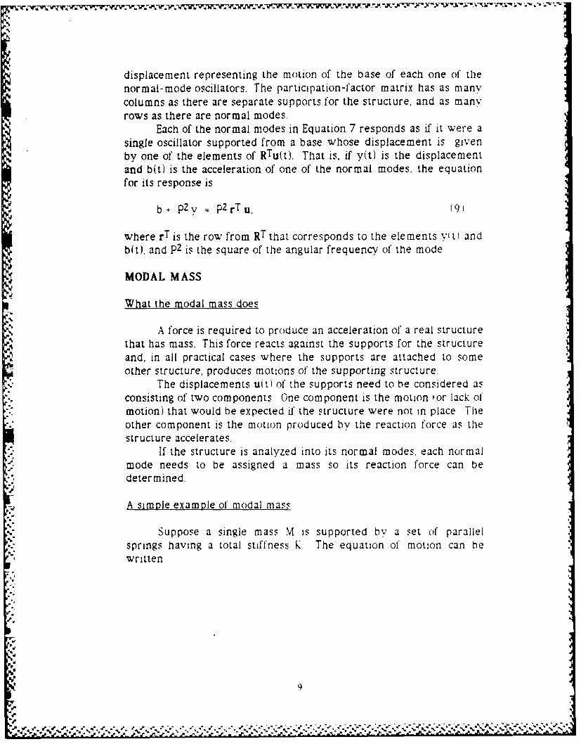
displacement representing the motion of the base of each one of thenormal-mode oscillators. The participation-factor matrix has as manycolumns as there are separate supports for the structure, and as manyrows as there are normal modes.
Each of the normal modes in Equation 7 responds as if it were asingle oscillator supported from a base whose displacement is givenby one of the elements of RTu(t). That is, if y(t) is the displacementand b(t) is the acceleration of one of the normal modes, the equationfor its response is
b- p2 y = p2rTu, (9.
where rT is the row from RT that corresponds to the elements ytt) andb(t), and p2 is the square of the angular frequency of the mode
MODAL MASS
What the modal mass does
A force is required to produce an acceleration of a real structurethat has mass. This force reacts against the supports for the structureand, in all practical cases where the supports are attached to someother structure, produces motions of the supporting structure.
The displacements u(t) of the supports need to be considered asconsisting of two components One component is the motion 'or lack ofmotion) that would be expected i' the structure were not in place Tleother component is the motion produced by the reaction force as thestructure accelerates.
If the structure is analyzed into its normal modes. each normalmode needs to be assigned a mass so its reaction force can bedetermined.
A simple example of modal mass
Suppose a single mass M is supported by a set of parallelsprings having a total stiffness K. The equation of motion can bewritten
9I,.
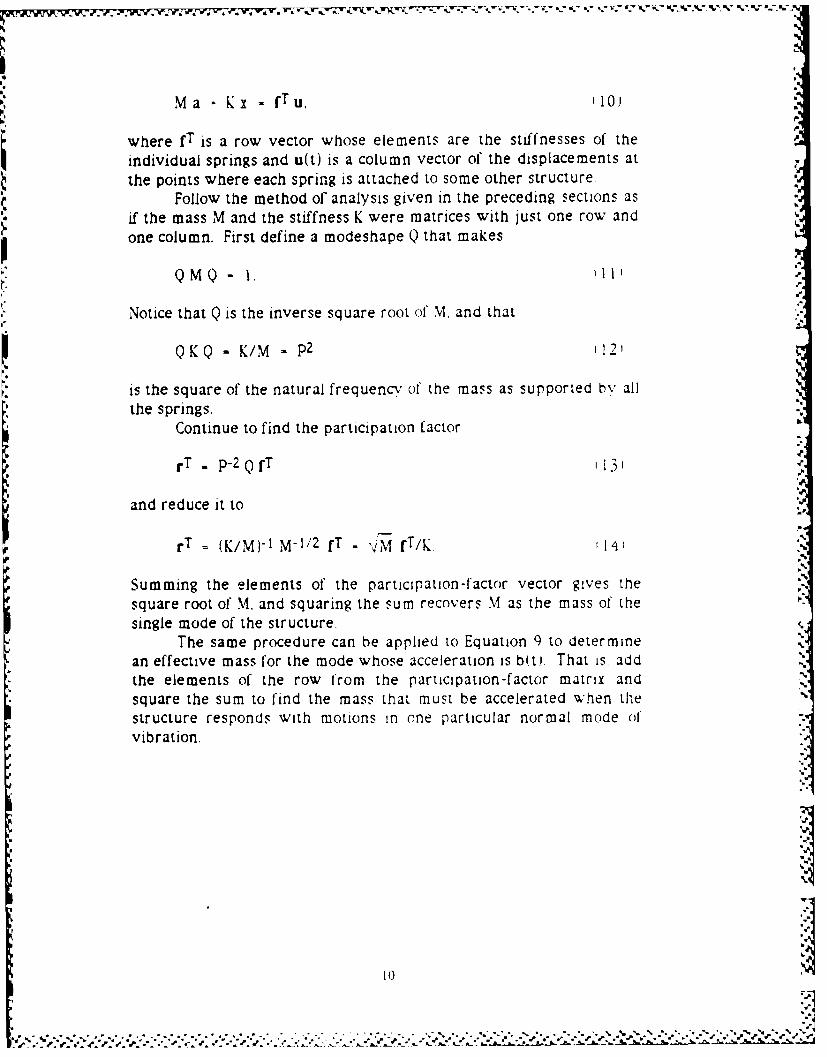
Ma Kx - fTu, .10)
where fT is a row vector whose elements are the stiffnesses of theindividual springs and u(t) is a column vector of the displacements at
the points where each spring is attached to some other structure.Follow the method of analysis given in the preceding sections as
if the mass M and the stiffness K were matrices with just one row andone column. First define a modeshape Q that makes
QMQ- .,L ,
Notice that Q is the inverse square root of M, and that1QKQ = K/M - p2 12'
is the square of the natural frequency of the mass as supported by allthe springs.
Continue to find the participation factor
rT . p-2 Q fT '13' C.
and reduce it to
rT = (KIM)-1 M-1/2 fT = 'IM fT/K 14.
Summing the elements of the participation-factor vector gives thesquare root of M, and squaring the sum recovers M as the mass of thesingle mode of the structure.
The same procedure can be applied to Equation 9 to determinean effective mass for the mode whose acceleration is b(t). That is, add f
the elements of the row from the participation-factor matrix andsquare the sum to find the mass that must be accelerated when thestructure responds with motions in one particular normal mode of'vibration.
I 0
T l li f ,i l il~ It j : l i ' a*Wll' i' l t '.l. 't I '\) V 5
a ti V.i ' " " .. .I , ' a 'll' ,. N Vl~ l' W . .' y y 1€.p1 .'J l ' .-:i lp i - , r l l it-. V .. w- w- w-q , W- n. , '
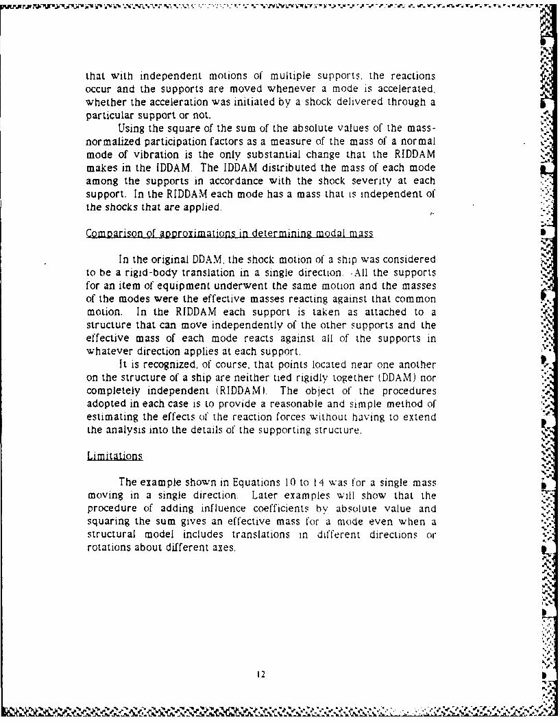
that with independent motions of multiple supports, the reactionsoccur and the supports are moved whenever a mode is accelerated,whether the acceleration was initiated by a shock delivered through aparticular support or not.
Using the square of the sum of the absolute values of the mass-normalized participation factors as a measure of the mass of a normal . -a
mode of vibration is the only substantial change that the RIDDAMmakes in the IDDAM. The IDDAM distributed the mass of each modeamong the supports in accordance with the shock severity at eachsupport. In the RIDDAM each mode has a mass that is independent ofthe shocks that are applied.
Comparison of aD)oroximations in determining modal mass
In the original DDAM. the shock motion of a ship was consideredto be a rigid-body translation in a single direction. All the supportsfor an item of equipment underwent the same motion and the massesof the modes were the effective masses reacting against that commonmotion. In the RIDDAM each support is taken as attached to astructure that can move independently of the other supports and theeffective mass of each mode reacts against all of the supports inwhatever direction applies at each support. *
It is recognized, of course, that points located near one another ilon the structure of a ship are neither tied rigidly together tDDAM) norcompletely independent (RIDDAM). The object of the proceduresadopted in each case is to provide a reasonable and simple method ofestimating the effects of the reaction forces without having to extendthe analysis into the details of the supporting structure,
VLi.mitations
The example shown in Equations 10 to 14 was for a single massmoving in a single direction. Later examples will show that theprocedure of adding influence coefficients by absolute value andsquaring the sum gives an effective mass for a mode even when astructural model includes translations in different directions orrotations about different axes.
.P
12
%'? ~~~a % %" ,S
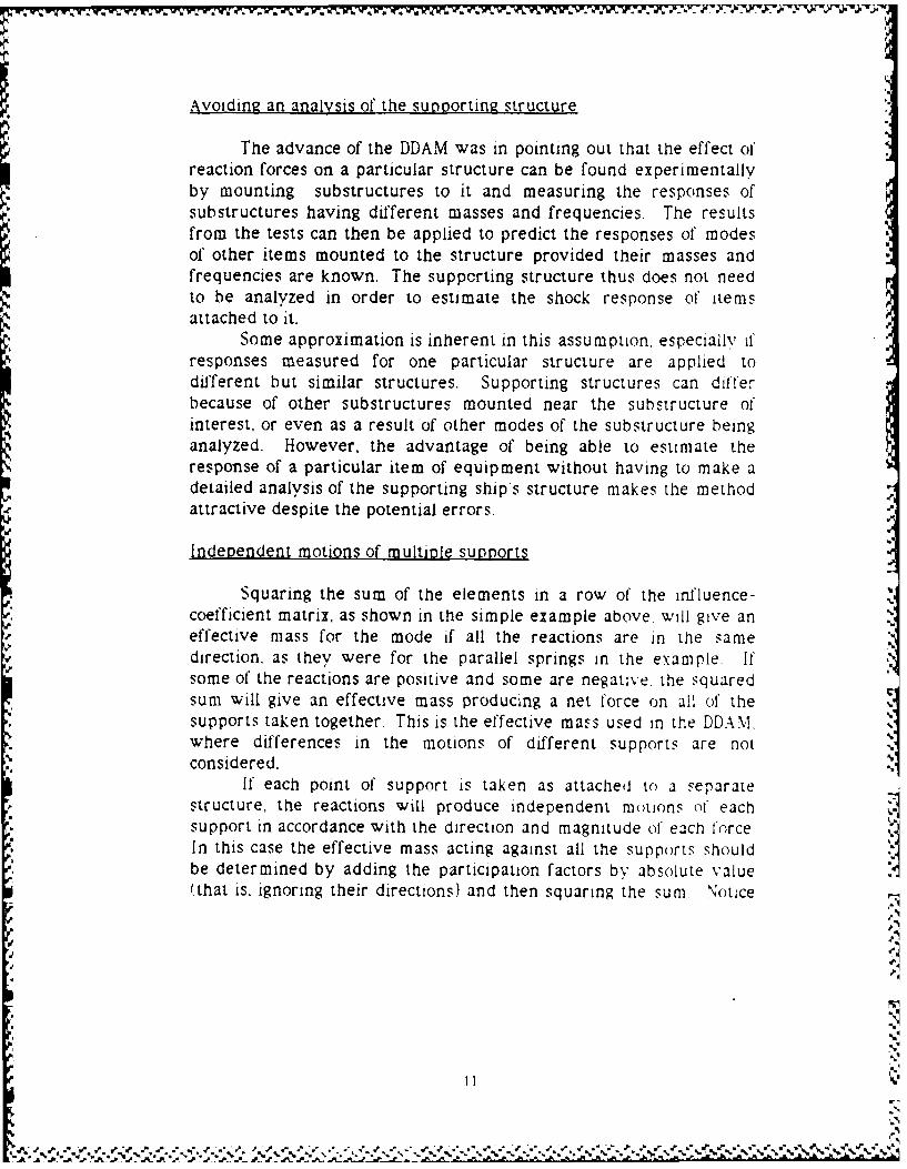
Avoiding an analysis of the supporting structure
The advance of the DDAM was in pointing out that the effect ofreaction forces on a particular structure can be found experimentallyby mounting substructures to it and measuring the responses ofsubstructures having different masses and frequencies. The resultsfrom the tests can then be applied to predict the responses of modesof other items mounted to the structure provided their masses andfrequencies are known. The suppcrting structure thus does not needto be analyzed in order to estimate the shock response of itemsattached to it.
Some approximation is inherent in this assumption, especially i'responses measured for one particular structure are applied todifferent but similar structures. Supporting structures can differbecause of other substructures mounted near the substructure ofinterest, or even as a result of other modes of the substructure beinganalyzed. However, the advantage of being able to estimate theresponse of a particular item of equipment without having to make adetailed analysis of the supporting ships structure makes the methodattractive despite the potential errors.
Indeoendent motions of multiole supports
Squaring the sum of the elements in a row of the influence-coefficient matrix, as shown in the simple example above, will give aneffective mass for the mode if all the reactions are in the samedirection. as they were for the parallel springs in the example. Ifsome of the reactions are positive and some are negatve. the squaredsum will give an effective mass producing a net force on all of thesupports taken together This is the effective mass used in the DDAM,where differences in the motions of different supports are not
Y considered.If each point of support is taken as attached to a separate
structure, the reactions will produce independent motions (o' eachsupport in accordance with the direction and magnitude of each forceIn this case the effective mass acting against all the suppo>rts shouldbe determined by adding the participation factors by absolute value
(that is. ignoring their directions) and then squaring the sum Notice
'%2
dI
.,-,, ,.,.-;,. -.,..,, ,...,..., ,. ,.-..;.. ,,,. ..... ;. .- .. ........-. * ' ' : : ii ?
The IDDAM inputs represent linear accelerations as a functionof effective mass and frequency. Applied through different supports,these accelerations can induce rotational and cross-axis responses of astructure. However, no inputs are supplied to show how the responseof a structure to a rotation of one of its supports might depend on themass moment of inertia about that support.
The RIDDAM uses the inputs developed for the IDDAM. As aresult of the lack of rotational inputs, it is necessary that the structurebe modeled so that its response depends on translational inputs only.This can be done in either of two ways: A support can be taken asirrotational, so that moments applied to it do not cause any rotation.Alternately, the joint at the support can be taken as pinned, so thatthe structure can rotate freely about that point without producing anyrotation of the supporting structure.
INPUTS 'Differential equations
The inputs to the analysis consist of predetermined solutions to
the equations
Mc Mp2z = MP 2 u,
where c(t) is the acceleration and z(t) is the displacement of anoscillator having mass M and frequency P. Here u, t1 is thedisplacement of the support for the oscillator, including both themotion induced by an external force and the motion resulting from thereaction of the mass of the oscillator against its support.
Because of the reaction, the acceleration of the oscillator varieswith its mass as well as with its frequency. In the DDA.M. all thesupport motions are taken as identical, so only one function is neededfor the base motion u(t), but in the IDDAM the supports can moveindependently and there is a separate Equation 15 for the effect ofeach support on each mode.
3I
13 I. ' '5'9" '5 5 * '5'S.U~5 ~ ~ 5 ,~. ~ *...*,.*'* "v~ '5 '.~- -
ApIl2ying, the inputs to the normal modes
The equation for the response of one of the normal modes,
b p2y = p2rT u, 16
uses a row from the influence-coefficient matrix to take a linearcombination over the motions of all of the supports and uses thatcombination to find the response of the mode. The process can bereversed by calculating responses first and then taking the linearcombination to obtain
b - rTc. 117)
where b(t) is the acceleration of the mode and c(M, P. t) is a columnvector of the solutions to Equation 15 for the mass and frequency ofthe mode and for the shock applied to each of the supports.
If the response accelerations c(M, P, t) for each support arealready provided. Equation 17 will give the responses for the modes ofthe substructure without the necessity of solving any differentialequations.
ACCELERATIONS, FORCES, STRESSES, AND DEFORM AT IONS
Accelerations %
Scale the matrix of modeshapes to
A =Q B.,l
where B(t) is a diagonal matrix of the accelerations bit) of theindividual modes and A!ti is now, by Equation 5, a matrix whosecolumns represent the accelerations of the coordinates of the structurein each mode. It is convenient at this point to keep the responses inthe different modes separate because of approximations that will bemade later in combining responses in different modes.
1.4
14 11"4
Forces
Multiply the matrix of accelerations by the mass matrix M toobtain
as a matrix whose columns represent the forces applied to thestructural nodes by the accelerations of each mode.
Stresses and deformations
The forces will produce time-varying stresses and deformationsin the structure that are proportional to the combination of forces ineach mode. The stresses and deformations at critical points on thestructure can be used, to estimate the ability of the structure tosurvive the accelerations given by the inputs.
WARPAGE
Additional deformations
The displacement-balance equation (Equation 2'.
X - K-1 F u - K-1 M a (20)
shows that the response x(t) of the structure depends on the motionsof its supports u(t) as well as on its acceleration att) The precedingmodal analysis accounts for the forces, stresses. and deformationsproduced by acceleration only. It is necessary to supplement theacceleration-generated responses with a check of any additionaldeformations 'and resulting stresses) that may be produced bydifferences in motions of individual supports.
Note that if the motions of the supports are all identical Ias
assumed in the DDAMI there will a displacement response hut noadditional deformation of the structure. There also is no warpingdeformation if the supports are not redundant or if the motions of the
1
15
supports can be described bv a combination of rigid-body
displacements and rotations
Effect of reaction lorces
The structure will resist warping deformation by generatingstatic forces that tend to decrease the differences between the motionsof its supports. Again, as in the case of the effect of modal mass onacceleration responses, an estimate of the effect of the reaction forcescan be made in terms of an experimental or analytical decrease inwarping with increasing static reactions of a structure against relativemotions of a standard or typical supporting structure.
SUMMARY *.
The preceding theory shows how the responses of substructurescan be estimated under standard conditions while mounted to aparticular supporting structure. The characteristics of the supportingstructure are evaluated by determining the responses it can producein oscillators having different masses and frequencies and the staticwarpage it can produce in redundant supports with differentreactions.
The structure of interest is then analvzed into oscillators havingdifferent masses and frequencies and into reactions against relativemotions of its supports Direct comparison with the responsesdetermined for the supporting structure then allows responses of thestructure to be estimated
The theory has the potential for being exact if the supportingstructure were identical from one substructure to the next. Inapplication, however, supporting structures tend to be similar but not %%identical. Then the accuracv of the nethod depends on how muchvariety is allowed in supporting structures before a new set ofcharacteristics must be applied
V P
hL%213-11
APPLICATION
UNITS
Convenience
The IDDAM is based on user-friendly engineering units in whichNewtons law is satisfied for forces in pounds, masses in pounds, andaccelerations in multiples of the acceleration of gravity. Theacceleration of gravity is defined as 386 inches per second per second(9.8044 meters per second per second with one inch equal to 0.0254meters). A pound of force is then 4.447 Newtons, while a pound ofmass is 0.4536 kilograms.
The tabulated inputs for the IDDAM give accelerations inmultiples of the acceleration of gravity (g) as a function of weights inpounds and frequencies in Hertz 'cycles per second).
Comouter "-
Most computer programs will not allow forces and masses bothto be entered in pounds A common convention for using suchprograms in the inch-pound-second system is to enter masses in unitsof 386 pounds. That is. weights in pounds are divided by 386 toobtain masses for entry into the computer program Forces can thenbe entered in pounds, with stiffnesses in pounds per inch and elasticmoduli in pounds per square inch. There ,s no accepted name for theunit of mass that weighs 3S6 pounds. although the term slinclh, hasbeen suggested as a parallel to t!e erm 'slug that is useC !'or thesimilar unit in the foot-pound-second system
17 S..
',7
* 4,% * . %~.* * S - ~ .S 555 -=
SCALING OF MODESHAPES
Arbitrary scaling
Some computer programs apply scale factors to the modeshapesto produce a modal matrix QS, where S is a diagonal matrix of scalefactors. One popular method of scaling makes the largest element ineach column of QS have the value unity, for example. The theory Lshown here was based on mass-normalized modeshapes in whichQTMQ - I was a unit matrix. Modifications are needed if modeshapes
have been scaled otherwise.
Effect of the scaling
With scaled modeshapes,
(QS)TMQS - S2 (21L
is diagonal but not a unit matrix. Also,
SQS)T K QS = S2p2 22)
is diagonal but its elements are no longer the squares of the naturalfrequencies. Using the scaled modeshapes in the transformations
a = QS b, X - QSy (231
converts the force-balance equation
Ma - Kx= Fu 24)
to
S2 b - S2P2y - (QS)TF u 25)
as the analog of the normal-mode equations.
18
A misinterpretation
The elements of S2 in Equation 25 have been referred to asmasses of the normal modes and even used as if they were masses insome calculations. One popular computer program refers to them asgeneralized masses" in its printed output. The elements of S2 have
completely arbitrary positive values that depend only on whatcriterion was used to scale the modeshapes and have no physicalsignificance.
Removing, th~e scale factors "
The scale factors contained in S must simply be removed step-by-step as the analysis proceeds. First, divide by the elements of S2
to obtain the squares of the natural frequencies asp2 - S-2 (S2 p2). (26 ) '
Next, recognize two kinds of participation factors. The mass-
normalized participation factor must be recovered from
RT - S-I Ip-2 (QS)T Fl. (27!
The responses of the scaled modes, however, must be found from theequation
b - P2 y p2 [p-2 S-2 (QS)TF1 u, 128)
so that the participation factor for this operation must be obtainedfrom
RIT - P-2S-2(QS)T F . 29)
Notice that any computer program that displays naturalfrequencies must have calculated a value of S2 in order to evaluateEquation 26, so it should not be necessarv to recalculate the scalefactors (Equation 21) in order to find what factors to remove.
19,, , .., .=,, .,,,.,)... o. ,,. ..,. . . -,. - -. .. . .. ..-. .,. ... .... ... . . ..., . . . . . .. . , . . - . - .. ' .. .'
, ( ,,," , , ,,. % 19 .. 1' . . . . a .. ' , *
Avoiding the scaling
Many computer programs begin a normal-mode analysis bvchoosing a modeshape matrix that reduces QTMQ to a unit matrixWith such programs the mass-normalized modeshapes arefundamental and subsequent scaling may be an option that need notbe selected.
If only scaled modeshapes are available from a particularprogram, it may be more efficient to remove the scale factors directlyfrom the modeshapes by dividing each column of QS bv its element ofS and then proceeding in a mass-normalized fashion, rather thandividing repeatedly by the scale factors as results are being calculated
SUPPRESSION OF TIME HISTORIES
Ile
The theory indicates that a supporting structure must becharacterized by a set of time-history accelerations c(iM, P. t thatdiffer for each mass M and frequency P of oscillator that may besupported from it. Moreover, the time histories cannot be oscillationsat the frequency P, because P is a lired-base frequenc3, and theessential feature of the supporting structure is that it cannot beconsidered to be a fixed base.
In addition, the response of a multimode structure withmultiple independent supports must be determined bv superposingseparate time-history responses for each mode and each support.Such combinations were impractical for routine analyses when DDAMwas under development about 1960.
Simglification
The IDDAM follows the lead established bv the DDAM insuppressing the time variation of the response acceleration. Itcharacterizes supporting structures in terms of the peak 'largestabsolute value) of acceleration that they can produce for an oscillatorof mass M and fixed-base frequency P.
20
Suppressing the time histories allows supporting structures tobe described by double-entry tables showing peak acceleration as a a-
function of mass and frequency, and eliminates the superposition oftime histories for multiple modes and multiple supports indetermining responses. It leads to problems, however, in estimatingthe combined effects of several modes whose individual responses aregiven only in terms of their peak values.
TIME HISTORIES AND COMBINATION RULES
Uner and lower bounds ,,.
It is clear that if the peak responses of several modes were allto occur in the same direction at the same instant of time, thecombined response would be the sum of the individual peaks and thatthis sum would be an upper bound for a time-history combination ofresponses. A lower bound may also exist if one of the peak values islarge enough to dominate the combination even if all the other peakshappened to occur simultaneously in the opposite direction. Eitheroccurrence is possible but unlikelv in a sum of time histories.
Combination rules
Simple and arbitrary rules can be defined to estimate a peakfrom a combination of responses that are described only by theirindividual peak values. Any rule adopted ought to define a combinedpeak falling in the range from the lower to the upper bound. The ruleshould select a likely value in that range and should be adjusted toavoid too much overconservatism or underconservatism.
The exact form of a combination rule is not important in areasof a structure where one mode predominates, so that the upper andlower bounds do not differ greatly A combination of engineeringjudgment, common sense, and experimental data are needed todetermine combination rules when several modes have comparablepeak values so that there is a large spread between upper and lowerbounds. Under this condition the best rule would be one that avoidsobvious conditions of great overestimates or underestimates, rather
2.• S .
• . m r _) -€. . w -- ,, --- --,r'-. ."1. r . • .'. .r .- we - e°
t" .- ,€" - _ " ." . J' " .%.. ." ." " - •* . °" ",% • . *" .') .* " " ., -. ) "-' -" J" =-
than a rule that attempts to recreate an actual combination of time-history responses.
COMBINING PEAK RESPONSES FROM DIFFERENT SUPPORTS
Rule
A suitable rule for estimating the peak acceleration b of' onemode from a collection of peak response accelerations c at differentsupports is
b * rTc, 130)
where rT is the row for the mode from the participation-factor matrix.
Discussion
Equation 30 is identical to Equation 17 that was used forcombining time histories. It presumes that the peak responses of themode produced by the motions of each support all occur at the sameinstant of time and in directions given by the signs of the elements ofthe participation factor. Such a combination could actually occurunder torpedo impact if the torpedo were to strike at the center of asymmetric array of supports, producing large responses to svmmetric
modes of the structure and no response for antisvm metric modesEquation 30 also reconciles the RIDDAM with the DDAM by
matching its results with those of' the DDAM for conditions in which allof the supports would have identical motions in a single direction.
in other cases the rule provides an estimated peak that fallsbetween the upper and lower bounds for the combination.
COMBINING PEAK RESPONSES FOR MODES OF DIFFERENTFREQUENCIES
The NRL Sum
An estimate of the peak stress or deformation from acombination of peak stresses or deformations from modes of different
22..
• '% " - v== "
• - = o)- ".44, *, -# '- # '. '.° '- . "- , ', . '- . ' . - . , - . -€ , . - , , - , -
frequencies is obtained by selecting the response having the largestpeak in absolute value and adding to it the square root of the sum of .5
the squares of the peak values of the other responses. This method ofcombination is usually called the ARL Sum.,
Estimated peaks obtained from the NRL Sum are alwayspositive numbers, but are to be interpreted as representing peaks thatmay occur in either direction.
Warning
The NRL Sum is a nonlinear combination and must always bethe last step in any calculation. In particular, if the NRL Sum is used ,to estimate a peak acceleration or a peak force from a combination ofmodal peaks, that estimated peak acceleration or force cannot be usedsubsequently to find stresses or deiormations.
.5
Estimating peak stresses and deformations
Equations 18 and 19 were especially written in a form to keepthe responses of the structure in each of its modes separate down tothe point of calculating stresses and deformations. If B is a diagonalmatrix of the peak accelerations b in each mode, the peakaccelerations of the structure in each mode are obtained by scaling themodeshape matrix according to
A - QB. 131
The peak forces on the structure in each mode are given bv thecolumns of
G =M A (32)
The stresses and deformations for each mode are obtained by solvinga separate static problem for the peak loads g that appear in eachcolumn of the matrix of forces. The loads may be positive or negative,depending on the signs of the participation factors and themodeshapes: these signs must be preserved through Equations 3 1 and32.
23

BStrain energy
The strain energy associated with a peak response isproportional to the square of the strain multiplied by the elastic .modulus of the material, or proportional to the square of the stressdivided by the elastic modulus. Summing the squares of the peakresponses thus gives a number proportional to the total energy aparticular part of the structure must accept The square root of thatsum represents the single deformation or stress that would account ?for the same energy.
The NRL Sum provides an estimated peak response that islarger than the energy-equivalent peak. but not larger than the upperbound.
SELECTION RULES FOR THE NRL SUMPeaks to be included
Peaks from the following sources are combined Into a singleNRL Sum:
I Stresses and deformations from normal operation of'equipment.
2 The warping deformations and stresses from dif erences in ;motions of multiple supports.
3 Stresses and deformations from some but not usually all of"the normal modes. The NRL sum overestimates the energies for the ='modes that are included, this overestimate can be considered as anallowance for additional modes of the structure that were not includedin the sum.
Modes to be selected
I For simple structures that can be modeled with six or fewerdegrees of freedom, the three modes of lowest frequency are usuallysufficient for determining an NRL Sum.
2. Structures of moderate complexity I up to 60 degrees offreedom) need only the lower-frequency modes to be included in the
24 I
2'
-* , ******* , **. *.- / -'%~~% % '*.. ' *. :.. .
00
NRL Sum. About half as many modes as degrees of freedom is anappropriate combination in most cases,
3. Complicated models with very many degrees of freedom 'asmay be obtained from a finite-element model) may generate a modal ',
thicket" in which many of the low-frequency modes represent ',
vibrations of lightweight parts of the structure. Here it may be betterto select modes in accordance with modal weight rather thanfrequency. Modes having weights at least 2 percent of the weight ofthe complete model are most likely to be significant. -
Prestresses and bolted ioints
Built-in stresses, including prestresses in bolts, are not includedin the NRL Sum of stresses. Bolted joints are expected to respond totensile 'loads by decreasing the clamping force rather than bystretching the bolts. Special checks need to be made, however, to besure than the clamping force is not exceeded by a peak load or thatshear stress from a transverse load does not combine with the tensilestress in a bolt to produce an excessive value of maximum normalstress.
SUMMARY
The procedures for applying the theory to practical calculationswith the RIDDAM can be summarized in eleven steps-
1. Make a mathematical model of the structure.2. Find the fixed-base normal modes and the mass-normalized
participation factors for the supports of the model.3. Add the participation factors for each mode bv absolute
value and square the sum to find the effective mass of each mode4. Refer to tables and formulas showing peak accelerations as a
function of the weight, frequency, and the location of an oscillatorrelative to the point of impact of a torpedo.
5. Combine the product of the participation factors and thetabulated accelerations for each support to find the peak accelerationof each mode.
6. Scale the modeshapes by the peak accelerations to find thepeak acceleration of each point on the structure in each mode.
25p -i
7. Multiply the peak accelerations of the structure by the massmatrix to find peak forces in each mode
8. Solve the static problem for each mode to find peak stressesand deformations at critical parts of the structure.
9. Calculate stresses and deformations from warping of thestructure caused by different motions of redundant supports..
10. Use the NRL Sum to combine stresses and deformations .
from operation, warping, and selected modes at critical points in thestructure.
11. Compare the estimated peak stresses and deformationswith allowable values.
.1_
-K
26.
pV
%"
'4.
.4
.4
I
.4-,
4,)
26 1"".'"", "- -'"-"",' . "" "- "-"-""-"",""-""-" - "" " ". ", "" ' " -', " °'" "- '"--', .,, " . -' ,',- K' .", '., YL ,, '.',? I
. , , , . . . , , - , , ", -"_, , , . - . - -
SPECIAL PROBLEMS
DESIGN SPECTRA
The accelerations c(M, P) representing the peak accelerationsfor oscillators having masses M and fixed-base frequencies P can becalled a design spectrum. Each point in a design spectrum is takenfrom a particular time-history response of a massive oscillator. Thattime history has been suppressed for simplicity.
The special problems described here arise from the suppressionof the time histories associated with the design spectra.
REPEATED FREQUENCIES
Time-hi tory combinations
Suppose
cl PI2Z - PI2 u 133i
and
CZ P22 Z2 -P2 2 u 34
are the responses of two oscillators to a support motion u't, If thetwo frequencies are the same, PI = P2 = P the time histories will beidentical and the peak accelerations will occur simultaneously
As the accelerations are scaled by participation factor and bymodeshape. and then used to calculate forces, stresses. anddeformations, the peaks will remain coincident in time but mavrepresent responses of different magnitude occurring in either thesame or opposite directions. The combined peak is given by thealgebraic sum of the individual peak values.
27
NRL Sum
if Modes I and 2 are the only two modes of the structure, theNRL Sum will add their peak stresses and deformations by absolute.Svalue (absolute value of the larger plus square root of the square ofthe smaller). This is an appropriate combination if both responses arein the same direction, but it may be a very large overestimate if themodes actually produce responses in the opposite directions.
If the structure has more than two modes, either or both ofModes I and 2 may be part of the square root of the sum of the -'
squares in the NRL Sum. Here their combined response will beunderestimated if they respond in the same direction, and will be Ioverestimated if they respond in opposite directions.
S1ecial rule
Modes with identical frequencies should have their peak _responses added algebraically rather than by NRL Sum. •VCLOSELY-SPACED MODES
Duhamel's interal
Formal solutions for Equations 33 and 34 can be written
tcl= P1
2 f v(t cosIPIft t dt (35)0 ""
and ..
Scz=P2z2 vt cosIP2(t t I dt 136, -.0 -..
where
.1*
28 S'-
I4
v*r TvVNXtM.rK V. a." W; W- V. 7- 7
°t.
duV 17
dta
is the velocity of the support.
Time-historv combinations A
When the two accelerations are scaled by participation factormodeshape, mass, and stress factor they will produce a contr!hbu'rn
s(t = D1 f vit 1 cos[PI~t -t )Idt '
tD, 7 vt cosIP2(t - t dt
fSo '
to a particular stress, where D1 and D2 are combinations ,_, al. therelevant factors for the two modes
If the frequencies are P1 - P - E and P2 - P - E, with an average
frequency P and a difference of 2E, the stress can be writen
t
st) ID1 " D2' J vft I cosIE!t t I coslPt-t i it
0* DI - D2 J v' t) sinlE ~ -t , siniPI I-t )j dt I3 ) -"
0 'a
AgDgroximation for closely-spaced frequencies
If Et is less than T1/2. the factors cosiElt t 1 and sinlE"' ca.be treated as positive-valued windows applied to the vel()c::v V,t
',..
,-a
2 S
".. ",",". -"."-. ","."."-"v .. ,- -.''.:.-."". "" . ," " "- "" . ,-"-""- ".,,_v .. .. ," ,- .--. v ,,".,., -#,'-", "-_- ." ,.,","
sinlEt' 1 - cosYEt' ".
with average values Et and Et over the range of
integration, from 0 to t. The averages can be considered as weightingfactors applied to the velocity of the support. The first average begins -
with a value of unity at the beginning of the response and decreaseswith increasing time, while the second begins at zero and increases.
A criterion
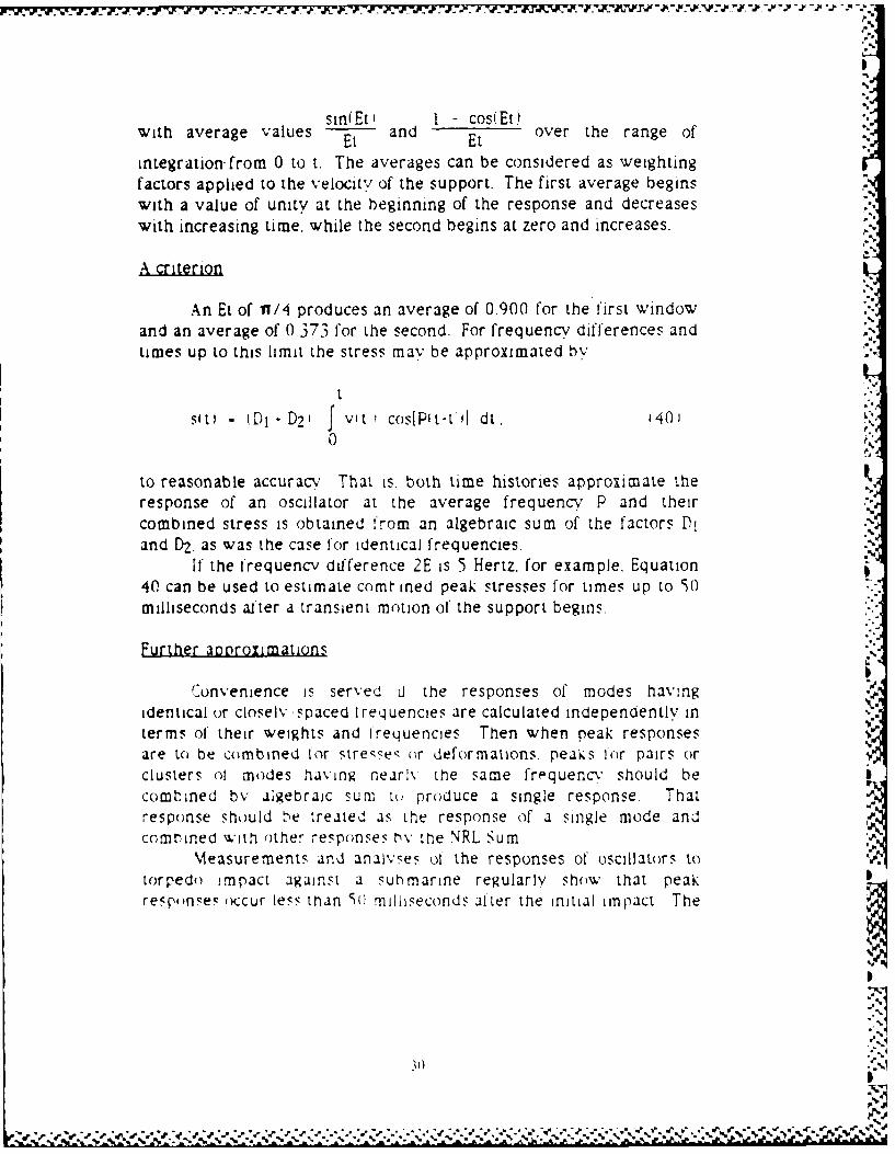
An Et of YI/4 produces an average of 0.900 for the first windowand an average of 0 373 for the second. For frequency differences andtimes up to this limit the stress may be approximated by
t
si t) , DI - D2 f Vit I cos[Pit-t 1 dt. 14 10
to reasonable accuracy That is. both time histories approximate theresponse of an oscillator at the average frequency P and theircombined stress is obtained from an algebraic sum of the factors DIand D2, as was the case for identical frequencies.
If the frequency difference 2E is 5 Hertz. for example. Equation40 can be used to estimate comt reed peak stresses for times up to S0milliseconds alter a transient motion of the support begins.
Further agoroximations
Convenience is served d the responses of modes hav:ngidentical or closelv-spaced Irequencies are calculated independently interms of their weights and frequencies Then when peak responsesare to be combined Ir stresse- ()r deformations. peaks for pairs orclusters ol modes having nearly the same fri-quen " should becombined by algebraic sum to produce a single response. Thatresponse should be treated as the response of a single mode andcombined with other responses hv the NRL Sum
Measurements and analyses ol the responses of oscillators to V.torpedo impact against a submarine regularlv show that peakrespf,)nsez occur less than S( milliseconds after the initial impact The
310
--
dpeak stresses and deformations from pairs or clusters of modes thatfall within a 5-Hertz range can then be combined algebraically ratherthan by NRL Sum.
RULES OF THUMB
Suppression of the time histories is seen to require a number offairly-arbitrary rules concerning selection of modes and methods ofestimating peak values from combinations of responses.
The combination rules suggested here appear to be based onrational criteria. The rules were chosen mainly to avoid obviously-inappropriate results and are subject to revision and reinterpretationin light of statistical results from experimental data.
31
-S. -e"w i u-e ), • . ' -• ) l")- . '..' -. % ., .% % % ° % . . .• % -.o5 .- ' ' , ,,,' .. ,.,',', ,,, ,, , ",.,_, ..,. . , , ,,# ,.-., ... ,, -..- ,.. , -..- - . -".,,.
EXAMPLES
A TEXTBOOK EXAMPLE
Structure
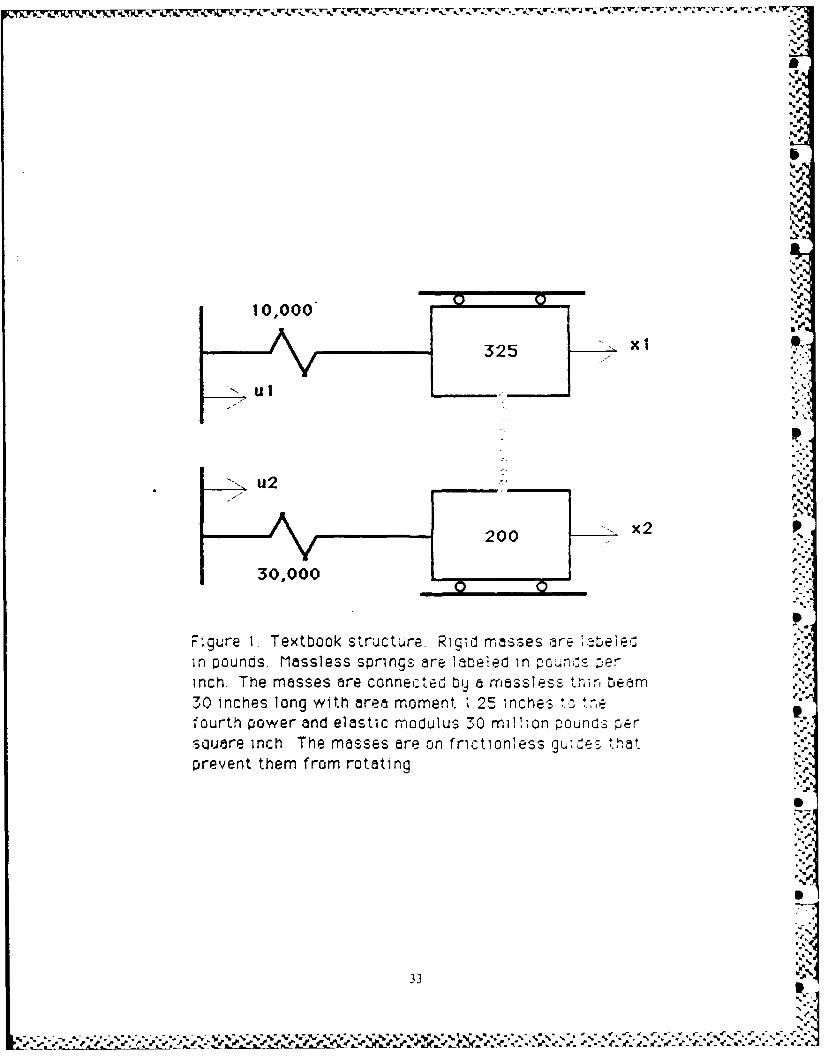
Rigid masses weighing 325 pounds and 200 pounds are '"
supported by springs having stiffnesses of 10,000 and 30,000 poundsper inch. as shown in Figure 1. Each mass is prevented from rotatingby a set of roller guides that are not considered part of the supportingstructure. The masses are connected by a thin and massless beam 30inches long. The cross-section of the beam has an area moment ofinertia of 1.25 in4 and the beam is made of a material with elasticmodulus 30 million pounds per square inch.
The structure is devised to illustrate the calculations: it is notintended to represent anything realistic.
Mass matrix
For coordinates xlit) and x,'t' representing displacements ofthe masses, the mass matrix is
V 325 0M = 0 200. pounds. 41
Stiffness matrix
Moving xl by one inch and holding all the other coordinatesfixed requires a force of 10,000 pounds to stretch the spring and an .additional force of
12 (30E6) 1.251.3(o13 = 16.666 67 pounds '42'
to bend the beam as a double cantilever An equal and opposite forcemust be applied to x2 to keep the other end of the beam from moving
32
7.
,%,
XII
325.
I ul
2ooI ....x2
30,000 "'
F~gure 1. Textbook structure. Rigid masses are:,abele,.in pounds. Massless spring-s are lateledn in : e '
inch. The masses are connected by a massless 1th , n b e am ,.3inches long with area moment 1 '25 ,nches *,o *.e:.-
fourth power and el asti c modul us 30 mnil1ion F ounos pe r ..
sq~uare inch. The Masses are oin frictionless gu, es ta t ":prevent them from rotating.',,
33 <
% •
- .# , -'. '," -." . -r", -. "t~r r- .. r~ rr 5 _ ,p , ¥ , . f- -.r,.r. .,'.¢ L" '. '.t-,r.,t ¢ € ".t,,' ', ,,.r,,.' , .1 t
.F.
I.
Here and in the following the usual computer notation of E6 is used,for example, to indicate multiplication by 10 to the 6th power
Moving x2 while the other coordinates are held fixed stretches ORits spring and also bends the beam. The forces from unit displacementof one coordinate at a time can be assembled into the stiffness matrix
K 'F 26666.67 -16666.672
L-16666.67 46666.67! pounds per inch. (43)
Suoort stiffness
A one-inch displacement of u1 (with everything else held fixed jwill put a force of 10,000 pounds onto xl. A similar displacement of ,,'u2 will put a force of 30,000 pounds onto X2. The support-stiffnessmatrix becomes
10000 (1
F 0 300001 pounds per inch. (44
Equation of motion
The three matrices M, K, and F allow the structure to bedescribed by the force-balance equation Ma - Kx = Fu. shown earlieras Equation I in the section on Theory.
Diagonalizing the matrices N,
The next step in the analysis is to find a matrix Q that will makeQTMQ be a unit matrix and also make QTKQ be a diagonal matrix, asshown in Equations 3 and 4. This can be done most easily by using anavailable computer program, such as in the example shown as Case Iin Appendix B. For the simple structure here, the modeshape matrix Qcan be calculated by hand. using the formula listed in Line 4 120 of thecomputer program to normalize on the masses and the formulasbeginning on Line 5610 to diagonalize the stiffnesses. The modeshapematrix ,
3
34
S.
r0.05198516 -(..o19351 147L0. 0 2 46 67 9 5 0.0662683 3,
is from a 10-digit pocket calculator. A direct check shows that itreduces
QT M Q -1.000 0.0007QTM Q Lo.ooo 1.000 =I (46
p. to the unit matrix and57.717 0.000-
QTK Q = L 0.000 257.668 2 i
to a diagonal matrix.The matrix Q can be used to represent the accelerations and
displacements of the structure in terms of normal-mode coordinatesby a - Qb and x - Qy. as shown in Equation 5.
Participation factor
The participation-factor matrix is
9.007 12.821p-2 QT F = -0.751 7.716' R T 8
The participation factor lets the equation for the normal-modecoordinates be written in the standard form b - p2y = P2RTu
(Equation 7). Each element of RTu is the effective displacement of thebase of one of the normal-mode oscillators
1%
Modal weights
Add along the rows of the participation-lactor matrix hVabsolute value and square the result to obtain
(9.007- 12.82112 = 476 pounds
35
ri for Mode I and
'0.751 7.716)2 72 pounds (50)
for Mode 2. This is the new procedure of the RIDDAM, as shown byexample in Equation 14.
Mode frequencies
When masses are in pounds and stiffnesses in pounds per inch,frequencies are given by the formulas
1386 (57.717) = 23.8 Hertz 151 ,
and
41
1- 13,6 1257.668 = 50.2 Hertz 52'* 2nf
for Modes I and 2. The normal-mode equations for motioniesssupports, b p2y - 0, identify the diagonal elements of PZ as squaresof the fixed-base natural frequencies of the modes. The factor of 386is the acceleration of gravity in inches per second per second, asneeded in the inch-pound-second system when pounds are used forboth masses and forces.
5' Innuts
The weights and frequencies of the modes serve as entries totables showing the peak accelerations of the modes. As an example.suppose that the tables specify a peak acceleration of 26 times theacceleration of gravity (g) for a weight of 476 pounds and a frequencyof 23.8 Hertz. and an acceleration of 119 g for 72 pounds at 50.2 Hertz.These are values at the point of impact for a torpedo At a point onthe hull 31 inches away from the point of impact the responseaccelerations would be 11 70 g and 53 55 g. These values representpeak accelerations of oscillators of mass M and fixed-base frequency P
36:4-WI
measured during tests with torpedo impacts or calculated fromEquation 15 during a computer simulation of an impact.
Peak accelerations of the modes
If the torpedo impacts in way of ul, with uz located 30 inchesaway from the impact, the peak accelerations of the modes areobtained by multiplying the tabulated responses by the participationf actors, or
9.007(26)+ 12.821 (11.70) = 384.19g 153;
for Mode 1 and
-0.751 (119) - 7.716 (53.55) = 323,82g (54,
for Mode 2. 'Equations 53 and 54 correspond to applying the participation
factors to the predetermined responses, rather than applying theparticipation factors to the support motions and then calculating the
responses. The two procedures give equivalent results for time-history calculations, as explained in Equations 16 and 17. The samecombination method is recommended for peak values in Equation 30 ifthe time histories have been suppressed.
Peak accelerations of the masses
Scale the shape for the first mode (the first column of Qi by384.19 and the shape for the second mode by 323.82 to obtain
19.97 -627'A 9.48 21.45J g
as the peak accelerations of the masses in each mode. The firstcolumn of A shows the peak acceierations of x I and x_ in Mode I andthe second column shows their peak responses in Mode 2. Peakaccelerations are shown separately for each mode, as recommended inEquation 3 1.
37
W7.177 7 7%, ."L%- *.=%7,.
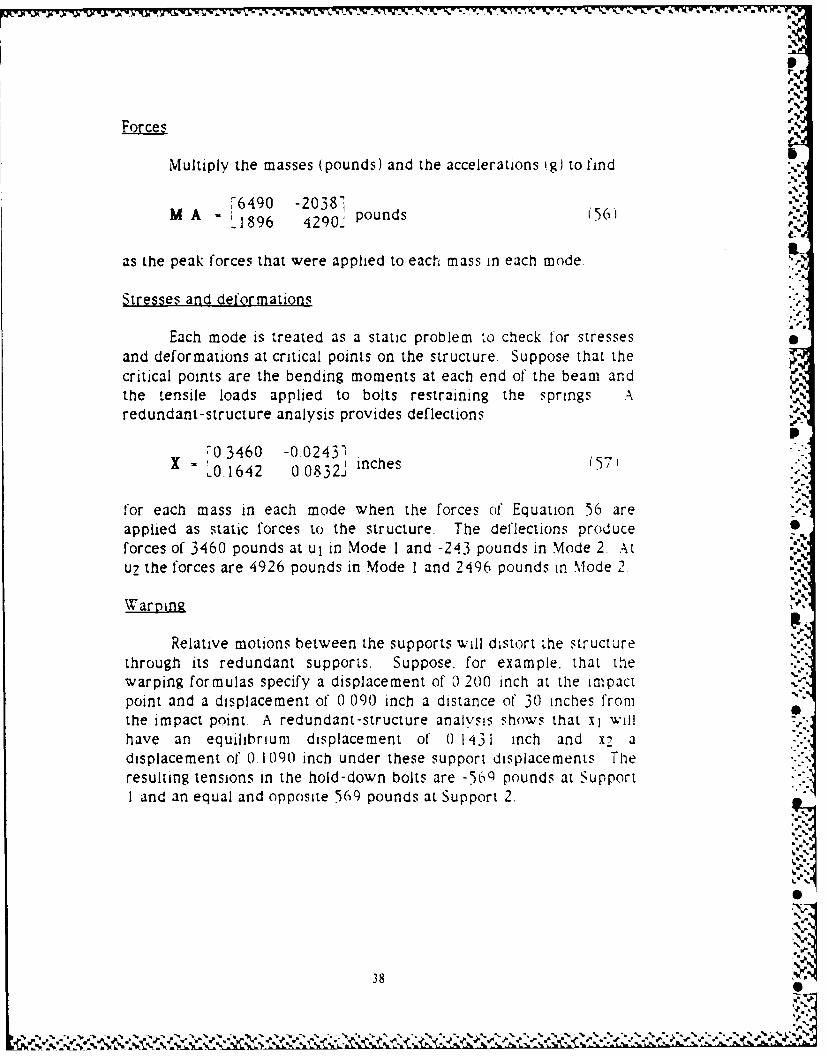
Forces
Multiply the masses (pounds) and the accelerations g) to find .
!6490 -20,3871M A - 0- pounds .56) . ,,'.=S
as the peak forces that were applied to each mass in each mode.
Stresses and deformations ;-
,.
Each mode is treated as a static problem to check for stressesand deformations at critical points on the structure. Suppose that the 'critical points are the bending moments at each end of the beam andthe tensile loads applied to bolts restraining the springs Aredundant-structure analysis provides deflections
P--0.3460 -0.0243'1"
X .0A .1642 0 _.0832.,, ,, inches (571)"-
for each mass in each mode when the forces of Equation 56 aresseapplied as static forces to the structure. The deflections produce
forces of 3460 pounds at Ul in Mode I and -243 pounds in Mode 2. Atuc the forces are 4926 pounds in Mode I and 2496 pounds in Mode 2
Warping ",
Relativens e os appd t supports will dstort the structure
through tsredundant supports. Suppose. for example. that tie ..warping formulas specify a displacement of '1 200I inch at the impactpoint and a displacement of 01 090. inch a distance of 30 inches fromthe impact point. A redundant-structre analvsns rhows that xl wllhave an equiibrium displacement of' 0 1131 inch and x7 adfsplacement of 0 eago inch under these support dsplacements Theresulting tensions in the hold-down bolts are -569 pounds at SupportMoeI the fores are 2pounn iuoad and24965pounst Support 2.o
38
NiRL Sum
Loads on the supports are to be combined by NRL Sum, subjectto the selection rules described earlier under Application." The forcesfrom warping and two modes (assuming no operating stresses)combine by the rule of the largest plus square root of the sum of thesquares in the form
3460 - (-243)2 -- (-569)2 4079 pounds (58)
as an estimate of the peak force applied to the bolts at ut, and
4926 - '(2496)2 . (569)2 = 7486 pounds (59)
for the bolts at u2.
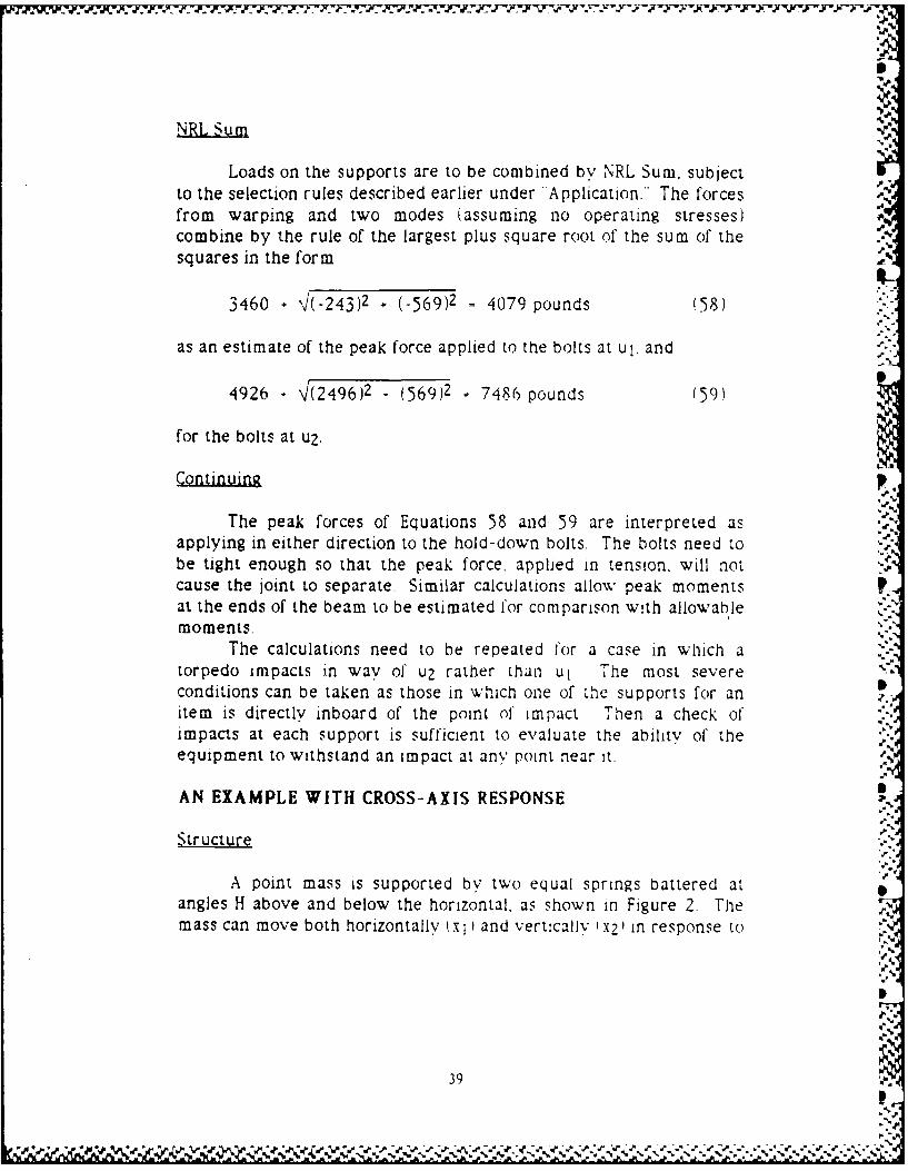
Continuing
The peak forces of Equations 58 and 59 are interpreted asapplying in either direction to the hold-down bolts. The bolts need tobe tight enough so that the peak force, applied in tension, will notcause the joint to separate. Similar calculations allow peak momentsat the ends of the beam to be estimated for comparison with allowablemoments.
The calculations need to be repeated for a case in which atorpedo impacts in way of1 u2 rather than ul. The most severeconditions can be taken as those in which one of the supports for anitem is directly inboard of the point of impact Then a check ofimpacts at each support is sufficient to evaluate the ability of theequipment to withstand an impact at any point near it.
AN EXAMPLE WITH CROSS-AXIS RESPONSE
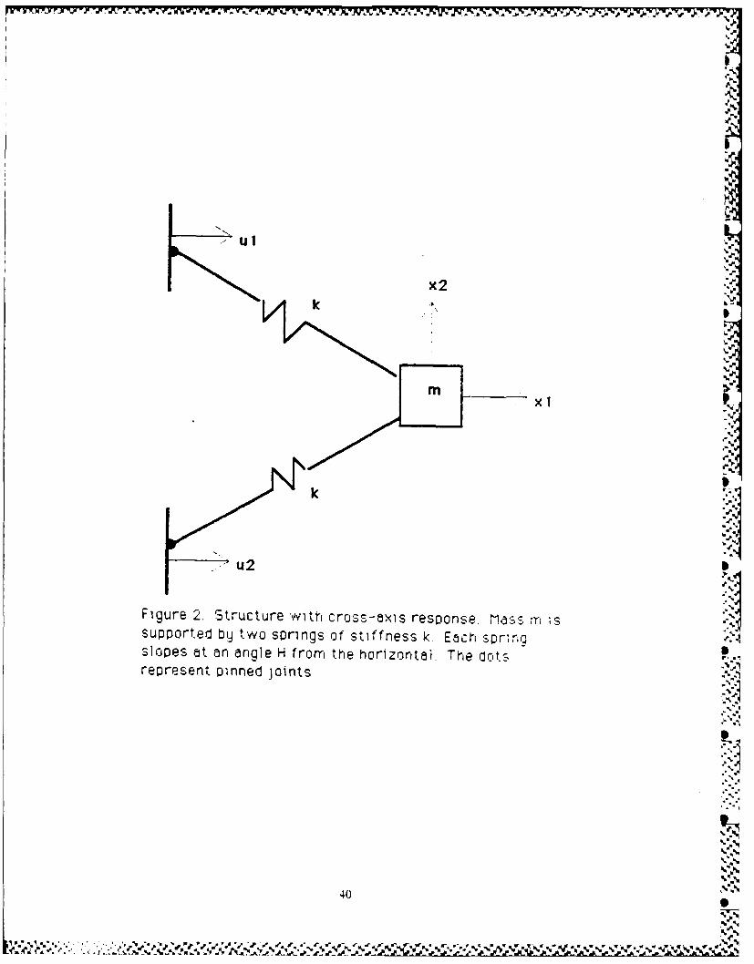
Structure
A point mass is supported by two equal springs battered atangles H above and below the horizontal, as shown in Figure 2. Themass can move both horizontally t x and vertically x21 in response to
39
N
..
k
k~
Figure 2. 'Structure with cross-ax'is response. M.dSS Tm 'Ssupported byj two springs of stiffness k. Each spr;r,Slopes at an anigle H from the horizontal, The dotsrepresent pinned joints
404
.A e W r C 'r.1 le
X'4"
the horizontal motions of its two supports. This is another textbookexample not intended to represent a realistic structure.
In this and in the following two examples the analysis ispresented in a form parallel to that used for the first example, butwithout back-references to the sections of the report on theory orapplication. Please refer to corresponding sections of the first examplefor appropriate references.
Matrices "S
The mass matrix,
- 0L mJ
represents motion of the mass in either of the two orthogonaldirections. The stiffness matrix I
F2 k cos 2 1H1 0! - 0 2 k sinZ(H)J (6..
includes factors for the components of force and deflection in eachspring produced by small displacements of the mass in each directionThe support-stiffness matrix
" k cos 2fH ) k cos 2tH) 7F 1 621 "L -k sinkH) cos(Hi k sinH) cos(H K''
shows the horizontal and vertical force per displacement on the massproduced by small horizontal displacements of each support.
Normal modes
The modeshape matrix
Q 4 /m '6'L0 '1/mi
41
* S. . . .. . . . ... S . -. ,S.
5, - .* * ~ . . , - -- .5 -- .' *. ~ - *' . * - *)~% . .% % '5 .. :. ~*~*' '% . - ** *.- * * ~*'%.N - '~ % ~ '\ 5 '.X* i
normalizes the mass matrix to a unit matrix, gives a frequency-squared matrix
QTKQ 2 (k/m) cos 2 (H) 0L 0 2 ik/m) sin 2 (H)L.
and a participation-factor matrix
T ' /2 .m/2 ("p-2 QT F = , ,-6--5'S -L -(-Im/2) cot(H) m.lm/2) cotEHL)"
Modal weigh t
Mode I (horizontal motion) has effective mass m, as obtainedfrom the squared sum of the first row of the participation-factormatrix. Mode 2 (vertical motion) has effective mass m cot 2 H , withthe square of the cotangent representing the effect of the lever armsthat act to magnify or diminish the effects of a vertical force on thehorizontally-directed supports and also act to magnify or diminish ,hemotions of the mass.
Waroin -
Relative horizontal motions between the two supports wilsimply displace the mass in the vertical direction without producingany stresses or deformations (The joints at the supports are pinned
Interoretation *1'
The simple example here shows that the matrix formalism isnot limited to unidirectional responses If cross-axis responses are -expected from unequal motions of supports. thev should be includedin the model of the structure. and can be treated on the same basis ason-axis responses.
ONO
42 S,-..,
AN EXAMPLE WITH ROTATIONAL INERTIA
Structure
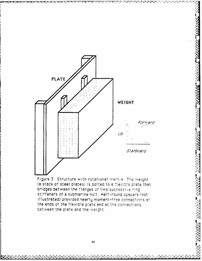
A steel plate is bridged between the flanges of two frames tocarry a weight made from a stack of steel plates, as shown in Figure 3.Four structures like this were built, installed in hulls, and tested withtorpedo impacts. The one analyzed here was tested in 1985 on theSITV (Submarine Impact Test Vehicle) There it served as simulatedequipment for research purposes.
Bouncing I
The structure was especially designed to be symmetric andnonredundant with two simple modes of vibration In one mode the "J.weight would translate as a rigid body and bend the plate as a beamThe stiffness of the plate (33 inches long, 22 inches wide, and I inchthick, with equal loads 6.5 inches from each end) can be obtained fromhandbook formulas as
12 (28E6) 22 (1)3/12(6.5)2 (3(33) 4(6.5)1 199,724 pounds per inch 1661
The stack of plates (859 poundsI and the center 20 inches of theflexible plate (124 pounds) both participate in the bouncing motion,while the 6.5 inches at each end of' the flexible plate connect from thefixed support to the moving load 1sav one-third ol 8I pounds, Arough estimate o. the total mass in the bouncing mode is thus i0 10pounds. The frequency should be ,.
.386 (199724)1 Hertz (<72J TY 1010
Analysis of measurements fronm the SITV test showed that thebouncing mode had a fixed-base frequency of 44 Hertz
%
5.:
43 t.
¢- , i,,/,w_' i% ,Q,.',,',,%''.''.''"
.' •.. ,.. , ==, W=: , "._",0"'.'" .0 , ,' " .%,r..' --,.'.,',,',--,-,..,,",, '_,=-'_ ', l. '.,'= '.r', " ." ," " *55
"'
WEIGHT'
''J
'
Figure 3 Structure with rokatiurnal re;-ta TFe iweight(a stack of steel plates) '-s olted to c -Wl~ pate thatbrdges betw een the 1fanges of tw./o succes 've r-ng Sstiffeners of a submarine hull. Half-round spacers (notillustrated) provwded nearly moment-free. oonnectl'r~s r tthe ends of the flexible plate and at tk,,e cr,-r~ect,,onsbetween the plate and the ''eg~
44
'b,' ' . . ,. ." " . b'' ."." " ' " " -- - r _' '" ,"'." , " " '"'" "" "" " ' """'""""'" """" , " "-' n ' " "" " " " "' n' "
" '
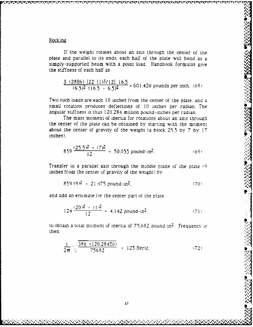
Rocking
If the weight rotates about an axis through the center of theplate and parallel to its ends, each half of the plate will bend as asimply-supported beam with a point load. Handbook formulas givethe stiffness of each half as
3 (28E6) 122 (1)3/121 16.5(6.5)2 (16.5 - 6.5)2 - 601,420 pounds per inch. (68.
Two such loads are each 1 0 inches from the center of the plate, and asmall rotation produces deflections of 1 0 inches per radian. Theangular stiffness is thus 120.284 million pound-inches per radian.
The mass moment of inertia for rotations about an axis throughthe center of the plate can be obtained by starting with the momentabout the center of gravity of the weight (a block 25.5 by 7 by 17inches),
i25.5)2 . (7)2859 12 = 50,055 pound-in 2. 1691
Transfer to a parallel axis through the middle plane of the plate 19inches from the center of gravity of the weight) by
859 (912 = 21.475 pound-in 2 , (70'
and add an estimate for the center part of the plate
(20,2 (I)124 12 = 4,142 pound-in2. (71'
to obtain a total moment of inertia of 75,682 pound-in 2 . Frequency isthen
1 '386 (120.284E6)=7125 Hertz. t72)2 Ti, 75682
457V
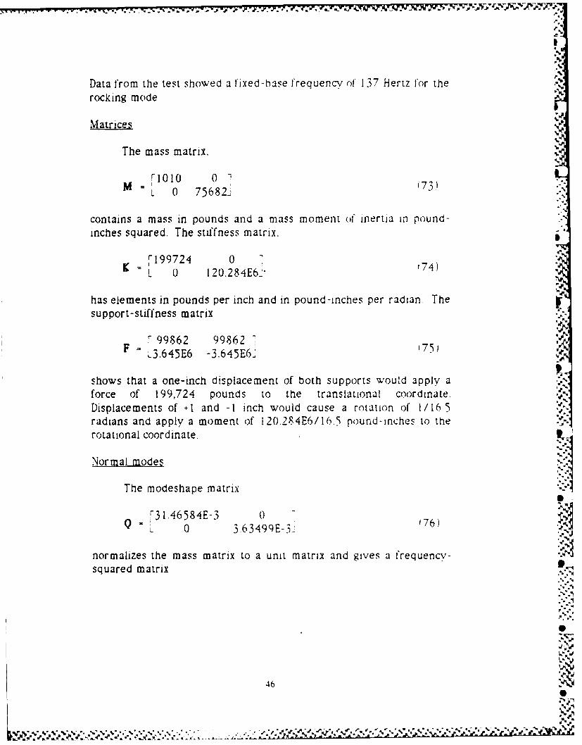
Data from the test showed a fixed-hase frequency of 137 Hertz for the
rocking mode
Matrices
The mass matrix. "
0%M = 1 1 7' "-'
L 0 75682J ""
contains a mass in pounds and a mass moment of inertia ui pound-inches squared. The stiffness matrix, -"
K IF199724 0 174)L 120.284E62
has elements in pounds per inch and in pound-inches per radian. Thesupport-stiffness matrix
F 99862 99862 -F= L3.645E6 -3.645E6J 175) A
shows that a one-inch displacement of both supports would apply aforce of 199,724 pounds to the translational coordinate.Displacements of .I and -1 inch would cause a rotation of 1/16 5radians and apply a moment of 120.284E6/16.5 pound-inches to therotational coordinate. I
Normal modes1
The modeshape matrix
3 1.46584E-3 0 7
L 0 3.63499E-3i 176)
normalizes the mass matrix to a unit matrix and gives a frequencv-squared matrix
p=.:
46
%
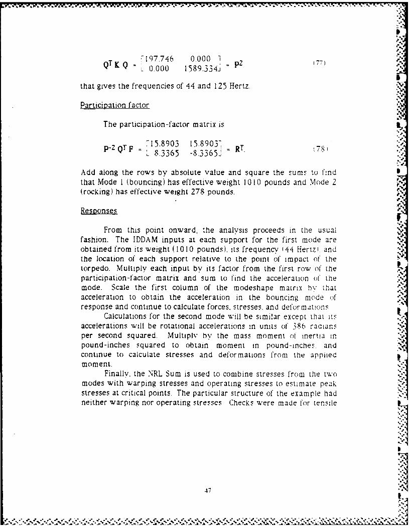
7'197.746 0.000 1QTKq Q= ; = p2 7)L 0.000 1589.3341
that gives the frequencies of 44 and 125 Hertz.
Particip~ation factor"i
The participation -factor matrix is
p_2QTF ,15.8903 15-89031 R, 8= 8.3365 -8.3365"
Add along the rows by absolute value and square the sums to findthat Mode I (bouncing) has effective weight 10 10 pounds and Mode 2(rocking) has effective weight 278 pounds.
Respo)nses
From this point onward, the analysis proceeds in the usualfashion. The IDDAM inputs at each support for the first mode areobtained from its weight ( 10 010 pounds), its frequency ( 44i Hertz i. andthe location of each support relative to the point of impact of' thetorpedo. Multiply each input by its factor from the first row of theparticipation -factor matrix and SUM to find the acceleration ofI themode. Scale the first column of the modeshape matrix hy thatacceleration to obtain the acceleration in the bouncing mode o.fresponse and continue to calculate forces. stresses, and deformat:(uns
Calculations for the second mode will be similar except thlat itsaccelerations will be rotational accelerations in units of 386 radians fper second squared. Multiply by the mass moment of' inertia inpound-inches squared to obtain moment in pound-inches, andcontinue to calculate stresses and deformations from the appliedmoment.
Finally. the NRL Sum is used to combine stresses from the twomodes with warping stresses and operating stresses to estimate pea-kstresses at critical points. The particular structure of the example hadneither warping nor operating stresses Checks were made f'or tensile
474. , ,"5
. . -"w'_'.. . . . .. " ." ,... ,..'-'.-" .. e _-' .=.
.€'.e'.-_. .'_'_..., .' , _'_,'.%, _.' .'=W'. 2 '' " ." - " . '% , @ " "J . ", " J p. @
.71
0'
loads in the bolts, stresses in the flexible plate, and stresses in thewelded brackets.
Interpretation
The example here shows that the formalism applies as well torotational responses as it does to translations, with the rotations given -
in radians, stiffnesses represented by moments per radian, andmasses represented by mass moments of inertia.
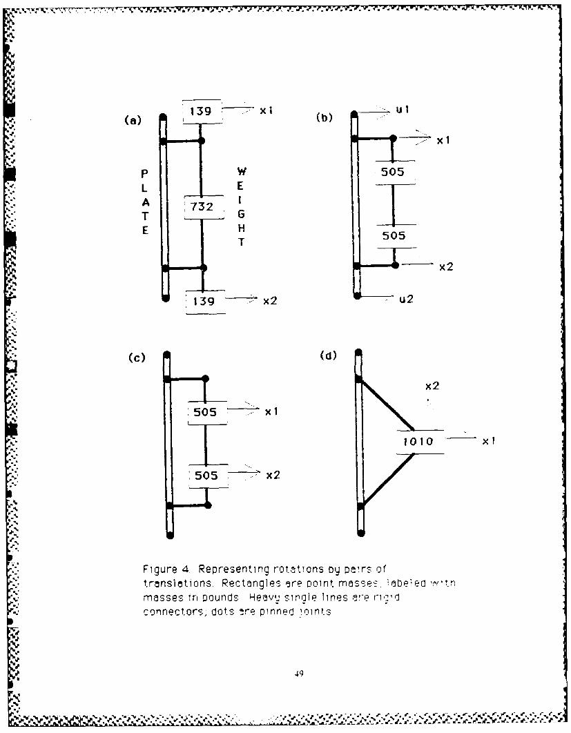
Alternate models using translations
Figure 4 shows four ways in which the two coordinates (onetranslation and one rotation) for the example could be replaced by apair of translational coordinates. In each case the total mass of 1010pounds is represented by point masses located so as to reproduce themass moment of inertia about an axis through the center of the plate,
The case marked ,a) is of special interest, since it shows thatplacing two weights of 139 pounds each directly over the supportpoints not only gives the correct mass moment of inertia but providesa total of 278 pounds to match the effective mass of the rocking mode.
Each of the configurations in Figure 4 can be analyzed toproduce results identical to the results obtained using a rotational J:_coordinate.
A REAL EXAMPLE
Source
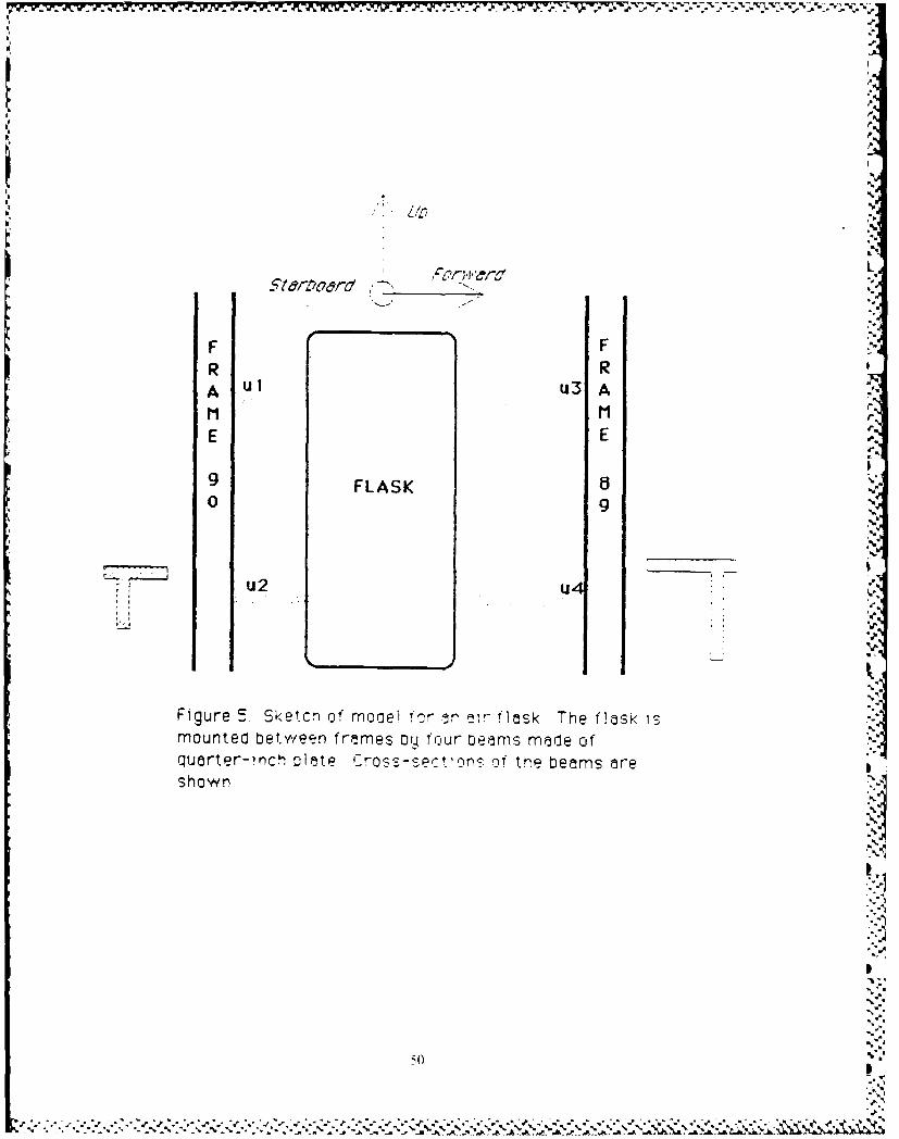
Figure 5 is adapted from a sketch in Appendix E of a report of.engineering analyses of submarine equipment done by a Navyshipyard.' The figure shows a 4-cubic-foot airflask supportedbetween two hull stiffeners by four beams built of quarter-inch steel
1M A Hataamer and M W Yarg~us Analysis (ifMSW Cool ng Pump & Piping andMiscellaneous Air Flasks Using Dynamic Analysis Method for Impact.Bremerton. Washington Puget Sound Naval Shipyard EngineeringDocument 449 (22 April 1I77)
48[ "€' ,,
~ * ~ > t
, * *~ *.*~ ** \* s***~*~ ~ *j**~.*' 3/
139 xl b ul(a} , (b)...
p W 505
L EA 732 6T G
E 505T
0 - ~ x2
139 - x2 " u2
(c) (d)
..
S. x2
505 X1 V
1010 X1
505 x2
Figure 4. Representing rotations oy pars of.. translations. Rectangles -re point masse- iebeiec wt,
masses in pounds Heavu sirle lines 5re rrd
connectors, dots 4re pinned i.intS
_ ; ,, . 'l n d l t49
FLASK
'I
F Fe E
mounted~ ~~ bewe ,r ne y orrwearnsmdeoqurerichS~tarbo r s-ec n of th beams are
9FLASK 60 9
;Iu2 u4
' S.
Figure 5 Sketch of mooei for n a flask The flask 13
mounted between frames D'y four Oearns made ofquarter-inch plate C-r o.- se.t~ns~ of the beams are
shown
50
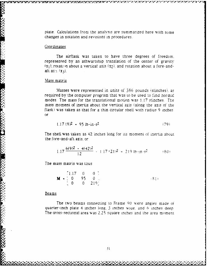
plate. Calculations from the analysis are summarized here with somechanges in notation and revisions in procedures.
Coordinates
The airflask was taken to have three degrees of freedom,represented by an athwartship translation of the center of gravityIXi), rotat..>rn about a vertical axis (x2). and rotation about a fore-and-aft aN,- (x3 ).
Mass matrix
Masses were represented in units of 386 pounds (slinches), asrequired by the computer program that was to be used to find normalmodes. The mass for the translational motion was 1.17 slinches. Themass moment of inertia about the vertical axis (along the axis of theflask) was taken as that for a thin circular shell with radius 9 inches.or
1.17 (9)2 95 lb-in-s 2 . (791
The shell was taken as 42 inches long for its moment of inertia aboutthe fore-and-aft axis, or
6(9)2 .4(42)21.17 2 1 17 2112 219 Ib- n-s2 '80'12
The mass matrix was thus
71.17 0 o
M= 0 95 0..0 0 219'
beams
The two beams connecting to Frame 90 were angles made ofquarter-inch plate 4 inches long, 3 inches wiu . and 6 inches deepThe cross-sectional area was 2.25 square inches and the area moment
51
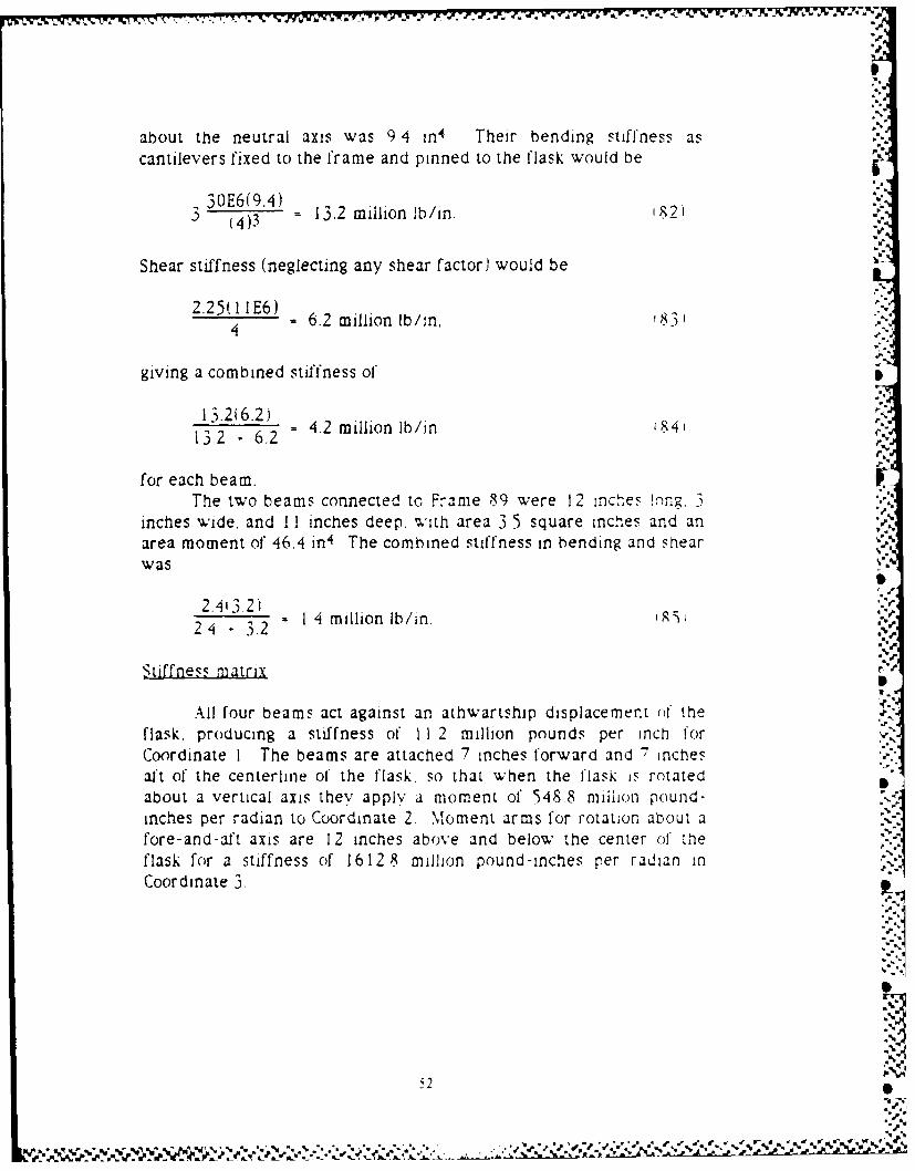
about the neutral axis was 9 4 in4 Their bending stiffness as
cantilevers fixed to the frame and pinned to the flask would be
30E6(9.4) 13mlo'313.2 millionlb/in. A2I
t 4)3
Shear stiffness (neglecting any shear factor) would be ,.2.25H I IE6)
E = 6.2 million lb/in, 831
giving a combined stiffness of
13.2(6.2)13 -6. =4.2 million lb/in 1R4'1 3 2 - 6.2
for each beam. rThe two beams connected to Frame 89 were 1 2 inches !nng 3
inches wide, and II inches deep, with area 3.5 square inches and anarea moment of 46.4 in4 The combined stiffness in bending and shearwas
2.4 3.2).24 - 3.2 = 14 million lb/in. ,..
Stiffness matrix
All four beams act against an athwartship displacement ol theflask, producing a stiffness of I I 2 million pounds per inch forCoordinate I The beams are attached 7 inches forward and 7 Inchesaft of the centerline of the flask, so that when the flask is rotatedabout a vertical axis they apply a moment of 548.8 milhon pound-inches per radian to Coordinate 2. Moment arms for rotation about afore-and-aft axis are 12 inches above and below the center of theflask for a stiffness of 16 1 2 8 million pound-inches per radian inCoordinate 3,
.,.-
5.
,=V
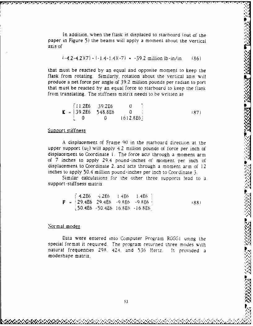
In addition, when the flask is displaced to starboard (out of thepaper in Figure 5) the beams will apply a moment about the verticalaxis of
(-4.2-4.2)(7) + (-1.4 1.)(-7) = -39.2 million lb-in/in (86) -,
that must be reacted by an equal and opposite moment to keep theflask from rotating. Similarly, rotation about the vertical axis willproduce a net force per angle of 39.2 million pounds per radian to portthat must be reacted by an equal force to starboard to keep the flask .from translating. The stiffness matrix needs to be written as
a
,I 1.2E6 39.2E6 0 - IK = 139.2E6 548.8E6 0 (87)
0 0 16 12.8E6 !
Suo ort stiffness
"
A displacement of Frame 90 in the starboard direction at theupper support (ul) will apply 4.2 million pounds of force per inch ofdisplacement to Coordinate I. The force acts through a moment armof 7 inches to apply 29.4 pound-inches of moment per inch ofdisplacement to Coordinate 2. and acts through a moment arm of 12inches to apply 50.4 million pound-inches per inch to Coordinate 3.
Similar calculations for the other three supports lead to a Isupport-stiffness matrix
4.2E6 4.2E6 I 4E6 I.4E6 -
F = 29.4E6 29.4E6 -9.8E6 -98E6 '88)L50.4E6 -50.4E6 16.8E6 -16.8E6
Normal modes
Data were entered into Computer Program RGGGI using thespecial format it required. The program returned three modes withnatural frequencies 298. 424, and 536 Hertz It provided amodeshape matrix.
5 3
'. J
.v , ,, , .; ,) v,,--,. ,. ,.,. ..,.;.. ..,.,... .. ..... ... ..,............. ..,. 1...
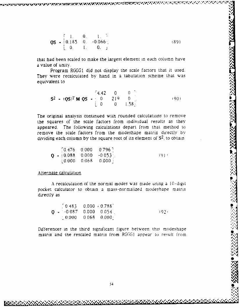
0
QS 0.185 0. -0.066, '89)L 0. 1. 0. l
OF
that had been scaled to make the largest element in each column have Il
a value of unity.Program RGGGI did not display the scale factors that it used.
They were recalculated bv hand in a tabulation scheme that wasequivalent to
'4.42 0 0S2 = QS)TM QS 0 219 0 190) S
L 0 0 1.58-,
The original analysis continued with rounded calculations to removethe squares of the scale factors from individual results as theyappeared. The following calculations depart from that method toremove the scale factors from the modeshape matrix directly bydividing each column by the square root of its element of S2, to obtain
?0.476 0.000 0.796 e
Q i 0.08 0.000 -0053'.LOO00 0,068 0.000
Alternate calculation 'J.
A recalculation of the normal modes was made using a I-digitpocket calculator to obtain a mass-normalized modeshape matrixdirectly as
0 483 0.000 0.788-Q - '-0087 0.000 0.054 192'
0.000 0.068 0.000"
Differences in the third significant figure between this modeshapematrix and the rescaled matrix from RG(]GI appear to result from
51
54 •
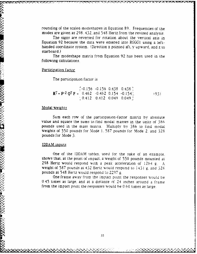
rounding of the scaled modeshapes in Equation 89.. Frequencies of themodes are given as 298. 432, and 548 Hertz from the revised analysis.
The signs are reversed for rotation about the vertical axis inEquation 92 because the data were entered into RGGGI using a left-handed coordinate system. (Direction x pointed aft, y upward, and z tostarboard.)
The modeshape matrix from Equation 92 has been used in thefollowing calculations.
Participation factor
The participation factor is
-0.156 -0.156 0.438 0.438"RT ,-P-2QTF= 0.462 -0.462 0.154 -0.154;. 193)
0.412 0.412 0.049 0.049J
Modal weights
Sum each row of the participation-factor matrix bv absolutevalue and square the sums to find modal masses in the units of 386pounds used in the mass matrix. Multiplv by 386 to find modalweights of 550 pounds for Mode 1, 587 pounds for Mode 2. and 328pounds for Mode 3.
IDDAM in )uts
One of the IDDAM tables. used for the sake of an example.shows that, at the point of impact. a weight of 550 pounds mounted at298 Hertz would respond with a peak acceleration of 1264 g. Aweight of 587 pounds at 432 Hertz would respond to i 431 g. and 328pounds at 548 Hertz would respond to 2297 g.
One frame away from the impact point the responses would be0 45 times as large, and at a distance of 24 inches around a framefrom the impact point the responses would be 0.60 times as large.
1) 55
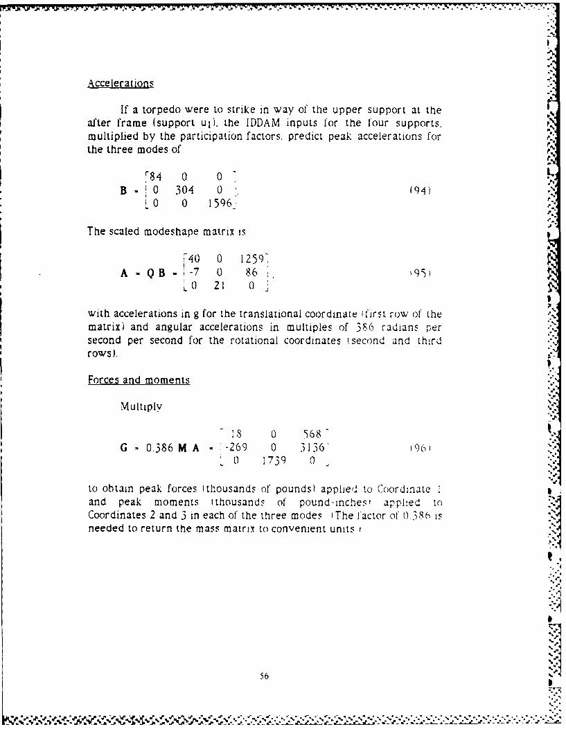
Accelerations
If a torpedo were to strike in way of the upper support at theafter frame (support uli, the IDDAM inputs for the four supports.multiplied by the participation factors, predict peak accelerations forthe three modes of
r84 0 0B . 0 30 4 0 9
B0 0 159629
The scaled modeshape matrix is
40 0 12597
A QB- -7 0 86 t'95L0 21 0
with accelerations in g for the translational coordinate (first row of the
matrix) and angular accelerations in multiples of 386 radians persecond per second for the rotational coordinates (second and third ..
rows).
Forces and moments
Multiply
s 0 568G - 0.386 M A -269 0 3136 1961
0 1739 0
to obtain peak forces (thousands of pounds) applied to Coordinate iand peak moments tthousands of pound-inches, applied toCoordinates 2 and 3 in each of the three modes IThe factor of 0386 isneeded to return the mass matrix to convenient units )
56
P5 t- ' C c- PS 7: 1 -4 16 r'' , 'z
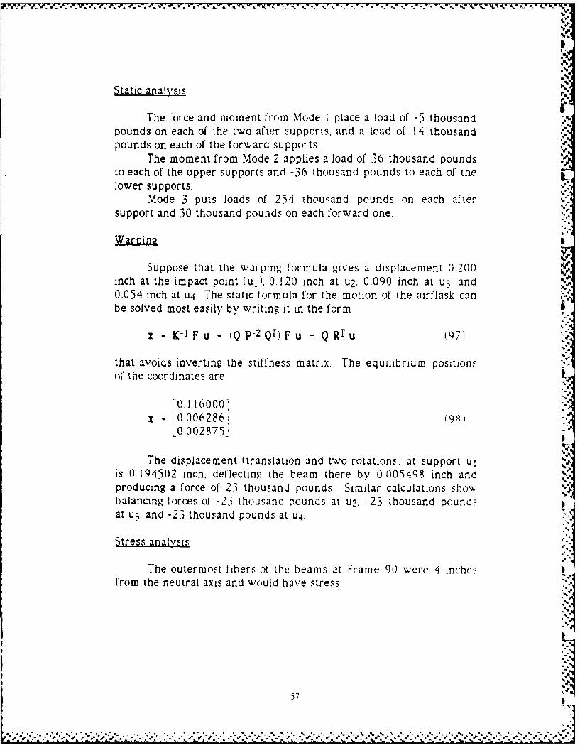
Static analvsis
The force and moment from Mode I place a load of -5 thousandpounds on each of the two after supports, and a load of 14 thousandpounds on each of the forward supports.
The moment from Mode 2 applies a load of 36 thousand poundsto each of the upper supports and -36 thousand pounds to each of thelower supports.
Mode 3 puts loads of 254 thousand pounds on each aftersupport and 30 thousand pounds on each forward one.
Warping
Suppose that the warping formula gives a displacement 0.200inch at the impact point (ul), 0.120 inch at u2, 0.090 inch at ul, and0.054 inch at u4. The static formula for the motion of the airflask canbe solved most easily by writing it in the form
z - K-1 F u = jQ p-2QThF u = Q RTu (97)
that avoids inverting the stiffness matrix. The equilibrium positionsof the coordinates are
0. 116000I 0.006286: 198
.0 002875_
The displacement (translation and two rotationsi at support ulis 0 194502 inch, deflecting the beam there by 0 005498 inch andproducing a force of 23 thousand pounds Similar calculations showbalancing forces of -23 thousand pounds at u2, -23 thousand poundsat u3, and -23 thousand pounds at u4.
Stress analysis
The outermost fibers of the beams at Frame 9) were 4 inchesfrom the neutral axis and would have stress
57
-,
4 '
94 = 1702 (99)
psi in bending per pound of force applied at the end of' the beam.,Shear stress would be
2.5 = 0.400 (100)
psi per pound.The beams at Frame 89 had their outermost fibers 6 inches
from the neutral axis, with stress 1 733 psi per pound there inbending, and with shear stress 0.286 psi per pound.
NRL Sum
The upper aft beam (ul) has loads, in thousands of pounds, of -5tMode 1), 36 (Mode 2), 254 (Mode .3), and 23 'warping'. Bendingstresses are -9, 62. 433. and 39 thousand pounds per square inch. TheNRL Sum of the bending stresses is
433 +(-9)2 (62)2 (39)2 507 thousand psi. 101
Shear stresses are -2, 14. 102. and 9 thousand pounds persquare inch, with an NRL Sum of i 9 thousand psi.
Check -
The calculation might as well stop here Ias it did in the original ibecause there is no chance that the support at the impacted framecould withstand the bending stress of 507 thousand pounds persquare inch or the shear stress of'1 19 thousand pounds per squareinch. The bending stress is more than ten times the vield stress for amedium steel and the shear stress is more than four times vield in Ishear. A redesign of the supports for the airflask is obviously needed
59.
"5%J
58
-.,.*4,
, %';" %'-, .5'%
il'm i I a~r ) ~r~ it ( '( m' q ~ w % q i ~ r II ° -' '-- - - ( w - - S- ,
6'.
APPENDIX A
A SHORT INTRODUCTION TO MATRIX ALGEBRA
MATRICES
A computer statement similar to
DIMENSION M(4,5) (A-I I
will reserve 20 memory spaces for numbers that can thereafter bereferenced as M(J,L). with J an integer in the range from I to 4 and Lan integer in the range from I to 5. The numbers are usually thoughtof as arranged in a rectangular array with four rows and five columns.designated simply by the letter M:
M(I.l) M(1,2) M(I.3) M(I,4) M(1,5' =lM(2.1) M(2.2) M(2.3) M(2.4) M(2.5)]M = M(3.1) M(3.2) M(33) M(3,4) M(3,5 1 A 2
LM(4.1) M(4,2) M14.3) M(4.4) M(4,5) -
SOME DEFINITIONS
The matrix with dimension M(4.5) is called a rectagular nJJZif-because it has a different number of rows than columns. A matrixwith dimension M(4,4) would be called a square matrix Theelements M(J,J) are called the dJigonal elements tlev would be theelements .Mi1 .1i, M2.2). M(,33), and M(4.4) for the matrix here
The sum of the diagonal elements is called the trace of thematrix; the trace of the matrix here would be M(I, -1 M,.2,2 - M 3.31M(4.4 I A svtmmetricmatrij is one in which every M 1Lb is equal to
the corresponding M(L.J' - that is. M( 1,2) = M(2.1 ' M1,3) = M3.Iand so on for all the pairs
SOME OPERATIONS
If matrix Q has elements Q j,L!, the matrix with elements y.'L.iis called the transpose of Q. designated bv QT Transpositioncorresponds to interchanging rows and columns in the array. ii the
59S...~
,', . -.- -.#.. .. .. . - - - - .- --. . . , - - . .,r .-.-." r .- ,-.-. - '.-, , ,_%_, .S .,- ',-,."-",,,-'- * "-.,
transposed matrix is equal to the original matrix tQT - Q), then thematrix must have been both square and symmetric.
Matrices of the same dimension are added or subtracted byadding or subtracting the corresponding elements. Matrices ofdifferent dimensions cannot be added to or subtracted from one '.another.
MATRIX MULTIPLICATION
The product of two matrices is written as if it were ordinarymultiplication. That is,
Z =MQ (A-3)
is the product of M and Q. The operation is not an element-by-element multiplication, however, but involves multiplying eachelement in a row of the first matrix by the corresponding element in acolumn of the second matrix and summing the products Each elementof Z is generated as
Z(J,N) - M(J,I) Q(I,N) - M(J,2) Q(2,N) - M1(j.3)Q(3.N)- M(J,4)Q(4,N) .... A-4) ,..
The equation can be abbreviated as
Z(JN) = MiJ,L) Q1L.N'. IA-51
where it is understood (the summaiton convention I that the productis to be summed over all possible values of the repeated index L.
The product matrix Z will have as many rows as there wererows in M, and as many columns as there were columns in Q.Moreover. M musL have exactly as many columns as Q has rows, sothat the indey L can be assigned to both and run through a singlerange of values
Because of' the rule for multiplication, it is not surprising thatthe matrix product QM is a different matrix from the product MQI
.5
6' 0
60 ,Q._U
. . . . . ... .. . .-.. ,..,-.. . .. ,-..-.. .. ; '.'.'..-...=.'¢'€'.'. '-. . . .'.... .. "..".". "€ :-..2€ ' -''.''*)S
V 1
MORE DEFINITIONS
A diagonallmatrix is one in which all of the elements other thanthe diagonal elements have values of zero. A unit matix (usuallydesignated by I) is a diagonal matrix in which each diagonal elementhas a value of unity.
The inverse of a matrix K is the matrix K-1 that makes
K-1 K = I (A-6)
he a unit matrix. Not all matrices have inverses. The definition of aninverse is reciprocal: K is also the inverse of K-I so that
K K-1 = I. (A-7!
If the transpose of a matrix is also its inverse, the matrix is saidto be unitary That is.
UTu I tA-s
defines U as a unitary matrix. A simple example is
,cos(H) -sin(H)-AU sin(H) cos, H),'
which is unitary for any angle H.
VECTORS
A matrix with only one column is called a column vector If amatrix X has dimension X(5,1 ). for example, it is a column vector withfive elements. It is usual to suppress the unit designation and showits dimension as X(5). Column vectors are designated by lower-caseboldface letters, such as x. in the present report
A matrix with only one row is called a row vector It isdimensioned Xi 1,.5. for example, and is designated here using thesymbol for transpose. IT Again the unit designation is usua.'v
61
,I'
I,,st, 'L .,'. .' ' . vlb.-2 - ,- 2,w.N, - ' .-' *. e i -"A '". ": "- . . _..-, . -,- ;. . .*- . -* a .J-\ , %' .
suppressed to show a row vector as dimension X(5), although this hasthe defect of not distinguishing it from a column vector.
All of the rules for adding, subtracting, and multipivingmatrices apply to vectors provided the unit dimension is understood.
SOME HELPFUL RELATIONS
The following rules can be verified by working out some simpleexamples. First, the transpose of a matrix product is obtained fromthe transposes of the factors taken in the reverse order, or
(MQ)T = QTMT. 'A-10
Similarly, the inverse of a product involves inverting and a'
interchanging the factors, as
(MQ)- = Q-I M- ,A-1l I.
If a matrix is symmetric. its inverse is also symmetric.However, the product of two svmmetric matrices, such as M -1 and K.is not a symmetric matrix, since
M- I K)T - KT M-T = K M -1 A-12-
is different from the original product M i KBoth the mass and stiffness matrices M and K for a structure
are necessarily svmmetric. If a stiffness matrix were not symmetric.for example, the structure could be run as a perpetual-motionmachine by moving it around a cycle in wvhich the smaller off-diagonalelement was worked during the compression phase and the largeroffdiagonal element was used to prov:de power during the returnstroke
Matrix elements for a structure can often by generated or --
checked by using the useful relations that zT K x/2 is the potential 'orstraini energy and vT M v/2 is the kinetic energy, where x is acolumn vector of displacements and v a column vector of velocities
62•.4"'€..,"
,.4,
USEFULNESS OF MATRIX ANALYSIS
The rules for addition, subtraction, and multiplication ofmatrices were chosen specifically so that matrix equations verysimilar to scalar equations, such as
Ma Kx = Fu, (A-0-p.
wou d expand into precisely the set of coupled differential equationsneeded to represent a structure with multiple coordinates. The great .
compaction of the notation and the resultant improvement incomprehension are exactly what is needed in analyzing complicatedstructures.
-.'
6.
°.
5-i
,.4
63
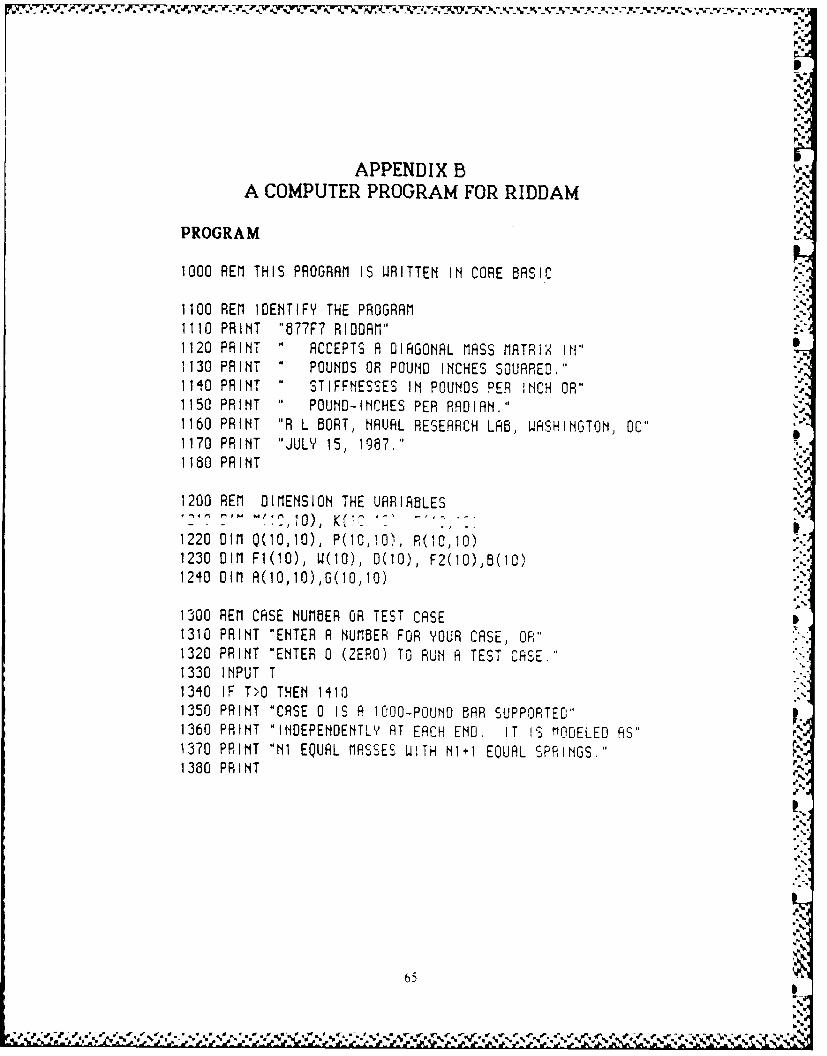
I.-
APPENDIX B
A COMPUTER PROGRAM FOR RIDDAM
PROGRAM
1000 REM THIS PROGRAM IS WRITTEN IN CORE BASIC
1100 REM IDENTIFY THE PROGRAM ,-1110 PRINT "877F7 RIODAM"
1120 PRINT " ACCEPTS A DIAGONAL MASS MATRIX IN"1130 PRINT " POUNDS OR POUND INCHES SOUARED."1140 PRINT " STIFFNESSES IN POUNDS PER INCH OR" '1150 PRINT " POUND-INCHES PER RADIAN."1160 PRINT "R L BORT, NAUAL RESEARCH LAB, WASHINGTON, OC"1170 PRINT "JULY 15, 1987."1180 PRINT
1200 REM DIMENSION THE UARIABLES10) K( W ' -
1220 DIM Q(0,10), P(0,0), R(I0,10)1230 DIM F1(00), W(O), 0(I0), F2(10),B(10)1240 DIM A(0,10),G(10,10)
1300 REM CASE NUMBER OR TEST CASE I1310 PRINT "ENTER A NUMBER FOR YOUR CASE, OR"1320 PRINT "ENTER 0 (ZERO) TO RUN A TEST CASE."1330 INPUT T1340 IF T>O THEN 14101350 PRINT "CASE 0 IS A 1000-POUND BAR SUPPORTED"1360 PRINT "INDEPENDENTLY AT EACH END. IT IS lODELED AS"1370 PRINT "NI EQUAL MASSES WITH NI I EQUAL SPRINGS."1380 PRINT
6.
65 b
"'4"'.<.4
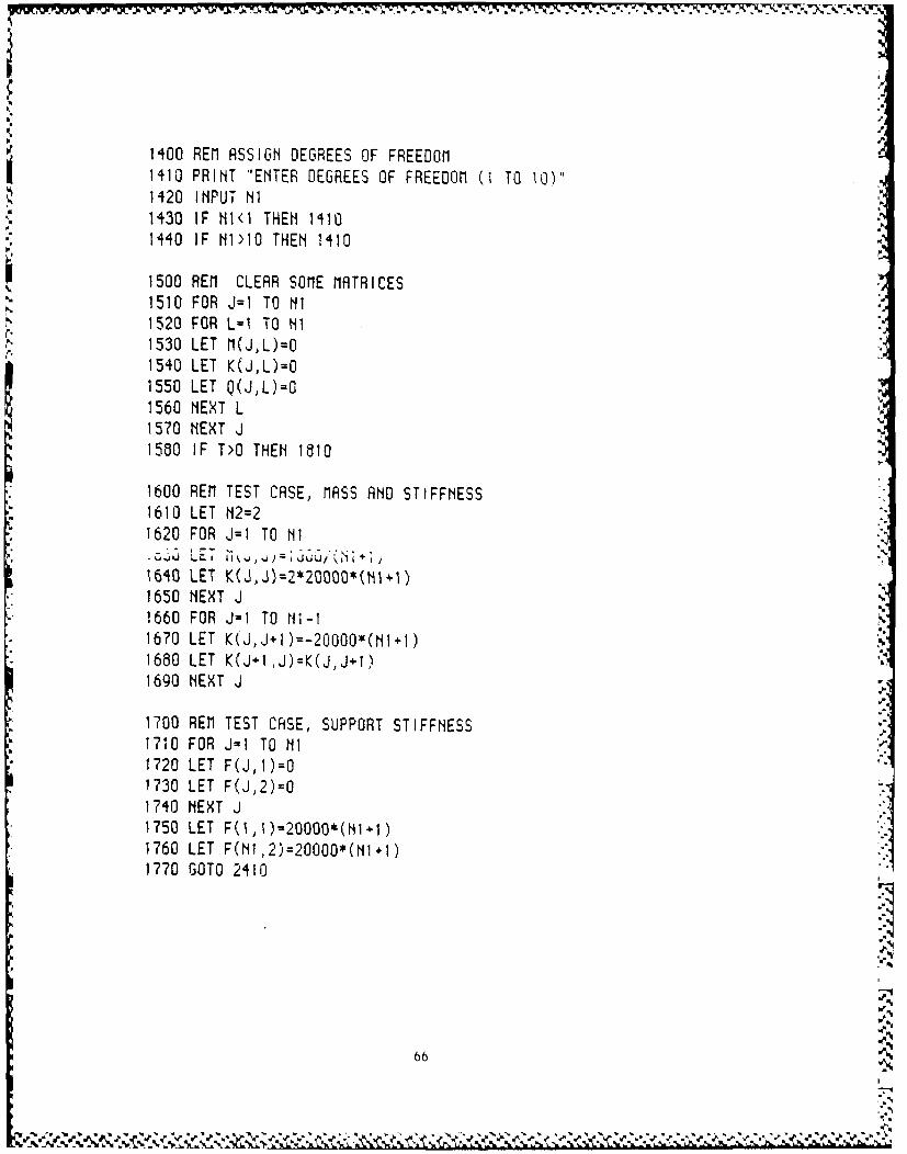
1400 REM ASSIGN DEGREES OF FREEDOM1410 PRINT "ENTER DEGREES OF FREEDOM (1 TO 10)"1420 INPUT NI1430 IF MI<l THEM 14101440 IF NII THEN 1410
1500 REM CLEAR SOME MATRICES1510 FOR J=1 To NI
1520 FOR L=- TO NI1530 LET M(JL)=O1540 LET K(JL)=O1550 LET Q(J,L)=O1560 NEXT L1570 NEXT J1580 IF T>O THEN 1810
1600 REM TEST CASE, MASS AND STIFFNESS1610 LET N2=21620 FOR J=I TO Ni,; sj L rT , .HiJ) =i - J16WO LET K(J,J)=2*20000*(NII)1650 NEXT J
1660 FOR J=I TO WI-11670 LET K(J,J+I)=-2OOOO*(NI+1)1680 LET K(J IJ)=K(J,J+I)1690 NEXT J
1700 REM TEST CASE, SUPPORT STIFFNESS1710 FOR J=1 TO NI1720 LET F(J,)=O"1730 LET F(J,2)=O
1740 NEXT J1750 LET F(II0Y200OO*(N1 1)1760 LET F(NI,2)=20000*(N1.1)1770 GOTO 2410
66
6 6 ' N
L'
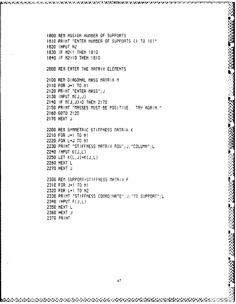
1800 REM ASSIGN NUMBER OF SUPPORTS1810 PRINT "ENTER NUMBER OF SUPPORTS (I TO 10)"1820 INPUT N21830 IF N2<I THEN 18101840 IF N2>10 THEN 1810
2000 REM ENTER THE MATRIX ELEMENTS
2100 REM DIAGONAL MASS MATRIX M2110 FOR J-1 TO NI2120 PRINT "ENTER MASS";J2130 INPUT M(J,J)2140 IF M(J,J)>O THEN 21702150 PRINT "MASSES MUST BE POSITIVE. TRY AGAIN."2160 GOTO 21202170 NEXT J
2200 REM SYMMETRIC STIFFNESS MATRIX K2210 FOR J=1 TO NI2220 FOR L=J TO NI2230 PRINT "STIFFNESS MATRIX RO.W".J;"COLUMN";L2240 INPUT K(J,L)2250 LET K(LJ)=K(J,L)2260 NEXT L2270 NEXT J
2300 REM SUPPORT-STIFFNESS MATRIX F2310 FOR J=1 TO NI2320 FOR L=I TO N22330 PRINT "STIFFNESS COORO!NATE"; "TO SUPPORT";L2340 INPUT F(J,L)2350 NEXT L2360 NEXT J2370 PRINT
67

2400 REM LABEL THE CASE2410 PRINT "THIS IS CRSE";T
2420 PRINT
2500 REM ECHO THE MASS MATRIX2510 PRINT "MASS MATRIX M =2520 FOR J=1 TO NI
2530 FOR L-1 TO NI2540 PRINT M(J,L),
2550 NEXT L2560 PRINT2570 NEXT J2580 PRINT
2600 REM ECHO THE STIFFNESS MATRIX2610 PRINT "STIFFNESS MATRIX K2620 FOR J=l TO NI2630 FOR L=I TO N12640 PRINT K(J,L),
2650 NEXT L2660 PRINT2670 NEXT J2680 PRINT
2700 REM ECHO THE SUPPORT-STIFFNESS MATRIX2710 PRINT "SUPPORT-STIFFNESS MATRIX F =
2720 FOR J=1 TO NI2730 FOR L=I TO N22740 PRINT F(J,L),
2750 NEXT L2760 PRINT2770 NEXT J2780 PPINT
68op
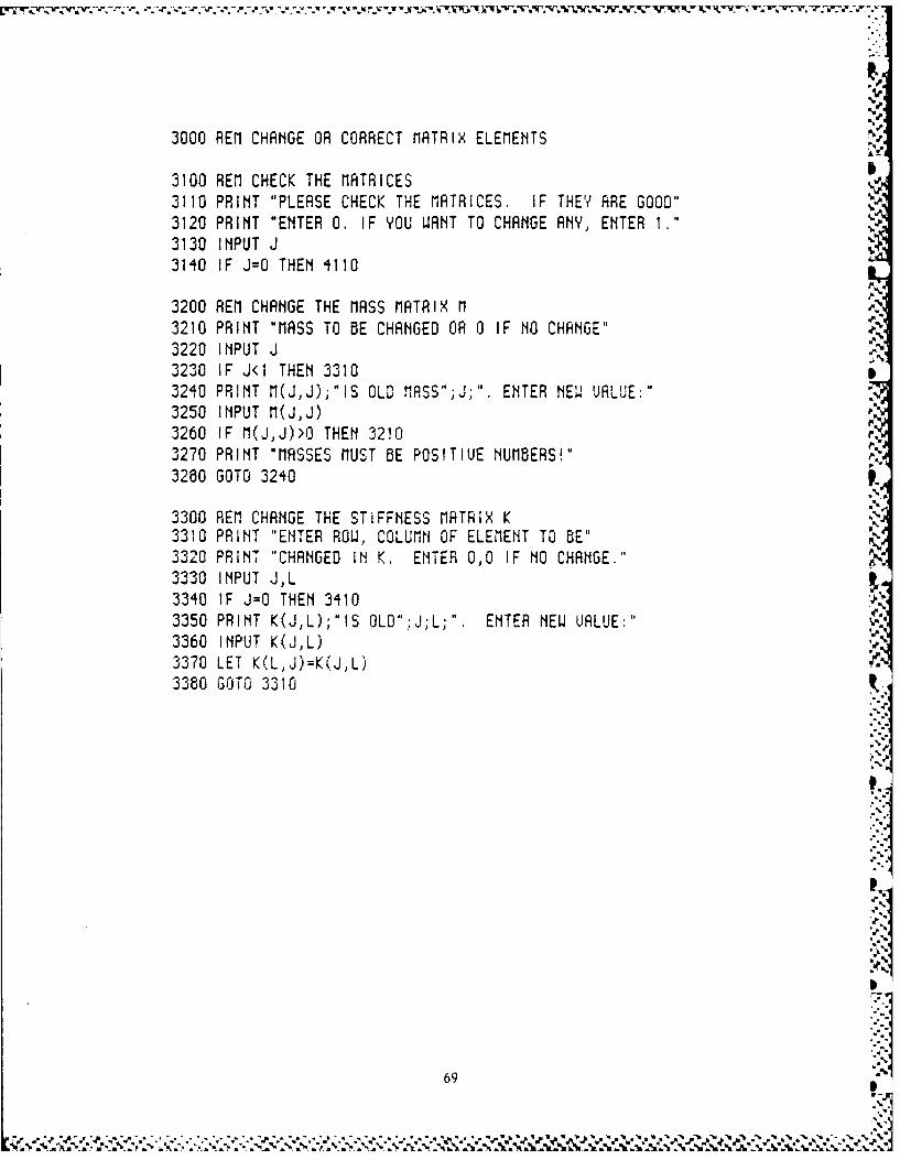
3000 REM CHANGE OR CORRECT MATRIX ELEMENTS
3100 REM CHECK THE MATRICES3110 PRINT "PLEASE CHECK THE MATRICES. IF THEY ARE GOOD"3120 PRINT "ENTER 0. IF YOU WANT TO CHANGE ANY, ENTER I."3130 INPUT J3140 IF J=O THEN 4110
3200 REM CHANGE THE MASS MATRIX M3210 PRINT "MASS TO BE CHANGED OR 0 IF NO CHANGE"3220 INPUT J3230 IF J<1 THEN 33103240 PRINT M(J,J);"IS OLO MASS";J;" ENTER NEw VALUE:"3250 INPUT M(JJ)3260 IF M(J,J)>O THEN 32103270 PRINT "MASSES MUST BE POSITIUE NUMBERS! "
3280 GOTO 3240
3300 REM CHANGE THE STIFFNESS MATRIX K 43310 PRINT "ENTER ROW, COLUMN OF ELEMENT TO BE"3320 PRINT "CHANGED IN K. ENTER 0,0 IF NO CHANGE."3330 INPUT J,L3340 IF J=O THEN 34103350 PRINT K(J,L);"IS OLD".:J;L;". ENTER NEW UALUE:"3360 INPUT K(J,L)370 LET K(L,J)=K(J,L)3380 GOTO 3310
69
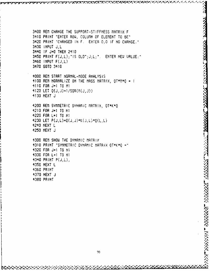
3400 REM CHANGE THE SUPPORT-STIFFNESS MATRIX F3410 PRINT "ENTER ROW, COLUMN OF ELEMENT TO BE"3420 PRINT "CHANGED IN F. ENTER 0.,0 IF NO CHANGE."3430 INPUT J,L3440 IF J=0 THEN 24103450 PRINT F(J,L);,IS OLD";J;L;". ENTER NEW URLUE:"3460 INPUT F(J,L)3470 GOTO 3410 e
.F
4000 REM START NORMAL-MODE ANALYSIS4100 REM NORMALIZE ON THE MASS MATRIX, QT*M*Q = I4110 FOR J=1 TO NI4120 LET Q(J,J)=1/SQR(M(J,J))4130 NEXT J
4200 REM SYMMETRIC DYNAMIC MATRIX, OT*K*Q4210 FOR J=1 TO NI4220 FOR L=1 TO NI4230 LET P(J,L),L)Q(LL)4240 NEXT L4250 NEXT J
4300 REM SHOW THE DYNAMIC MATRIX4310 PRINT "SYMMETRIC DYNAMIC MATRIX QT*K*Q =4320 FOR J=1 TO NI4330 FOR L=I TO Ill4340 PRINT P(J,L'),4350 NEXT L
4360 PRINT4370 NEXT J1380 PRINT
70
a,..¢ r . .. ........ -a .* .- - a . ."'V a .a -a -a%.
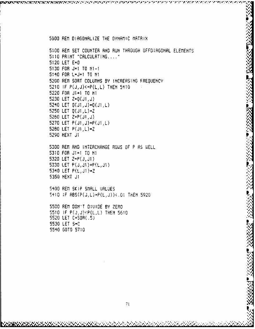
5000 REM DIAGONALIZE THE DYNAMIC MATRIX
5100 REM SET COUNTER AND RUN THROUGH OFFOIRGONAL ELEMENTS5110 PRINT "CALCULATING .... "5120 LET E=O5130 FOR J=1 TO Ni-I5140 FOR L=J I TO NI5200 REM SORT COLUMNS BY INCREASING FREQUENCY5210 IF P(J,J)<=P(L,L) THEN 54105220 FOR J1=I TO NI5230 LET Z=Q(JI,J)5240 LET Q(J1,J)=Q(JI,L)5250 LET Q(JI,L)=Z5260 LET Z=P(JI,J)5270 LET P(JIJ)=P(JI,L)5280 LET P(J1,L)=25290 NEXT JI
5300 REM AND INTERCHANGE ROWS OF P AS WELL5310 FOR JI=I TO NI5320 LET Z=P(J,JI)5330 LET P(J,JI)=P(L,JI)5340 LET P(L,JI)=25350 NEXT J1
5400 REM SKIP SMALL UALUES5410 IF ABS(P(J,L)+P(L,J))<.G1 THEN 5920
5500 REM DON'T DIUIDE BY ZERO5510 IF P(J,J)<P(L,L) THEN 56105520 LET C=SOR(.5)5530 LET S-C5540 GOTO 5710
71
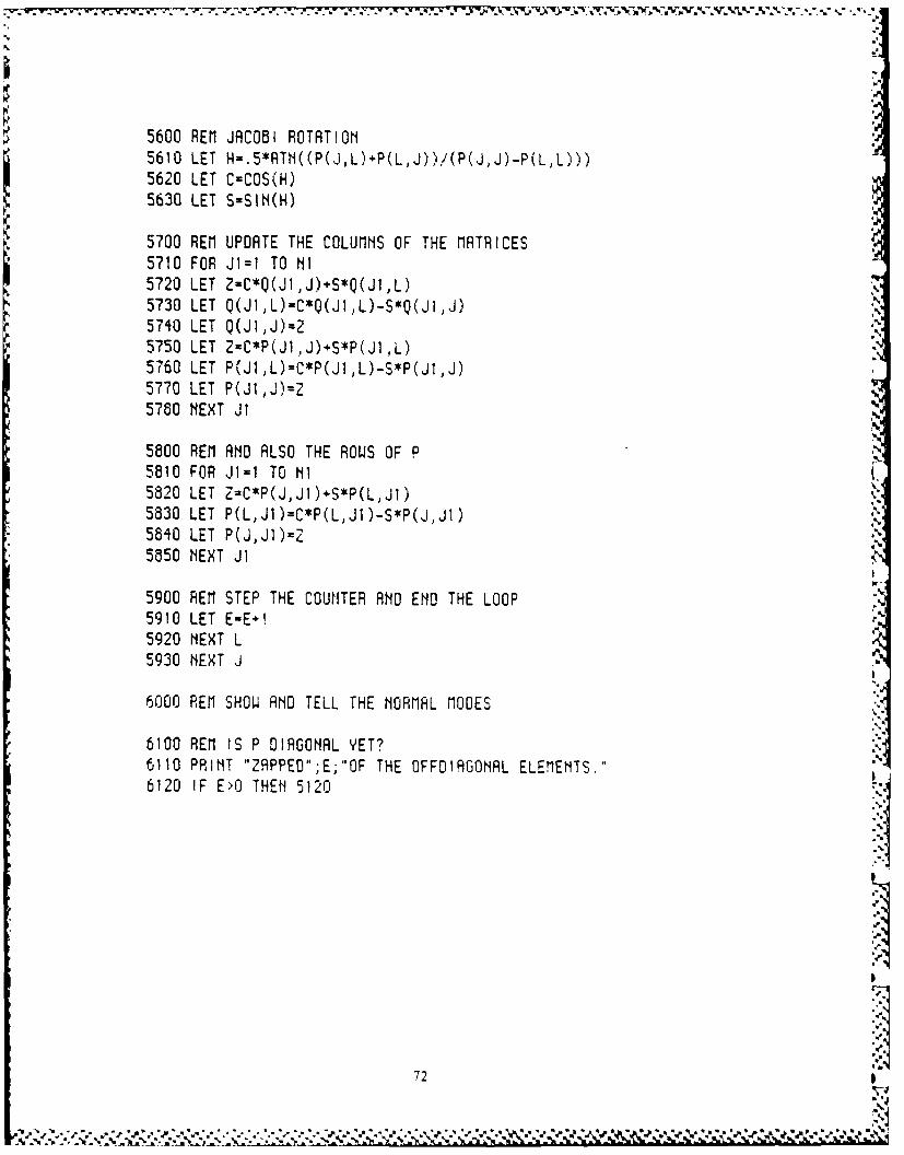
5600 REM JACOBI ROTATION5610 LET H=.5*ATN((P(J,L) P(LJ))i(P(JJ)-P(LL)))5620 LET C=COS(H)5630 LET S=SIN(H)
5700 REM UPDATE THE COLUMNS OF THE MATRICES5710 FOR JI=1 TO NI5720 LET Z-C*Q(JI,J)+S*Q(JI,L)5730 LET Q(J1,L)=C*Q(JIL)-S*Q(JIJ)5740 LET Q(JI,J)=25750 LET Z=C*P(JIJ) S*P(JI L)5760 LET P(JI,L)=C*P(JI,L)-S*P(JI,J)5770 LET P(JI,J)=Z5780 NEXT JI
5800 REM AND ALSO THE ROWS OF P5810 FOR JI=I TO NI5820 LET Z=C*P(J,JI) S*P(L,JI)5a30 LET P(L,JI)=C*P(L,JI)-S*P(J,JI)5840 LET P(J,J1)=e5850 NEXT Ji
5900 REM STEP THE COUNTER AND END THE LOOP5910 LET E-E I5920 NEXT L5930 NEXT J
6000 REM SHOW AND TELL THE NORMAL MOOES
6100 REM IS P DIAGONAL YET?6110 PRINT "ZAPPED";E;"OF THE OFFOIAGONAL ELEMENTS."6120 IF E>O THEN 5120
72
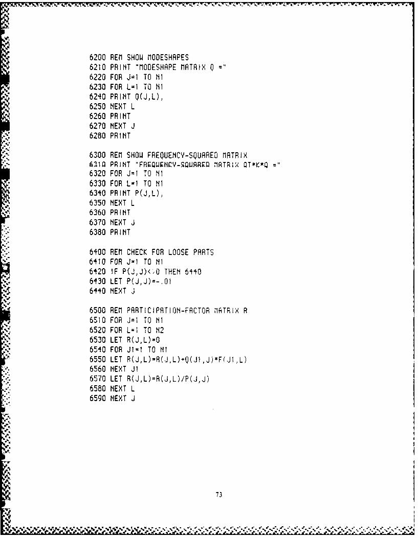
w. "... V. A. V, r.;-. 97-77..
6200 REM SHOW MODESHAPES6210 PRINT "MOESHAPE MATRIX Q6220 FOR J=1 TO NI6230 FOR L=I TO NI6240 PRINT Q(JL),6250 NEXT L6260 PRINT6270 NEXT J6280 PRINT
6300 REM SHOW FREQUENCY-SQUARED MATRIX6210 PRINT "FRUQWNQY-=WARRF MATRIX T*K*Q6320 FOR J=1 TO NI6330 FOR L=1 TO NI6340 PRINT P(JL),6350 NEXT L6360 PRINT6370 NEXT J6380 PRINT
6400 REM CHECK FOR LOOSE PARTS6410 FOR J=1 TO NI6420 IF P(J,J)<"O THEN 64406430 LET P(JJ)=-.016440 NEXT J
6500 REM PARTICIPATION-FACTOR MRTRIX R6510 FOR J=1 TO Ni6520 FOR L=I TO N26530 LET R(JL)=O6540 FOR JI=I TO Ni6550 LET R(J,L)=R(J,L)+Q(.JI,J)*F(.JI,L)6560 NEXT JI6570 LET R(JL)=R(J,L)/P(J,J)6580 NEXT L6590 NEXT J
73
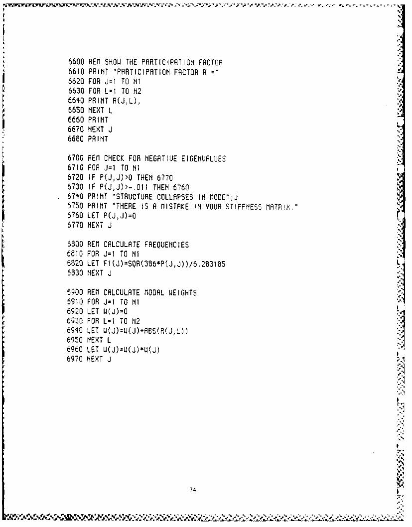
6600 REM SHOW THE PARTICIPATION FACTOR6610 PRINT "PARTICIPATION FACTOR R =6620 FOR J=1 TO NI6630 FOR L=I TO N2660 PRINT R(J,L),6650 NEXT L6660 PRINT6670 NEXT J6680 PRINT
6700 REM CHECK FOR NEGATIUE EIGENUALUES6710 FOR J=l TO NI6720 IF P(J,J)>O THEN 67706730 IF P(J,J)>-.011 THEN 67606710 PRINT "STRUCTURE COLLAPSES IN MODE";J6750 PRINT "THERE IS A MISTAKE IN YOUR STIFFNESS MATRIX."6760 LET P(J,J)=O6770 NEXT J.-
6800 REM CALCULATE FREQUENCIES6810 FOR J=l TO Ni6820 LET F(J)=SQR(386*P(J,J))/6.2831856830 NEXT J
6900 REM CALCULATE MODAL WEIGHTS6910 FOR J=I TO NI6920 LET W(J)=O6930 FOR L=I TO N2690 LET U(J)=W(J)+ABS(R(J,L)) I6950 NEXT L :
6960 LET W(J)=W(J)*u(J)6970 NEXT J
71
.V
.74-
.. b '- % ~ , ****
~A * ..
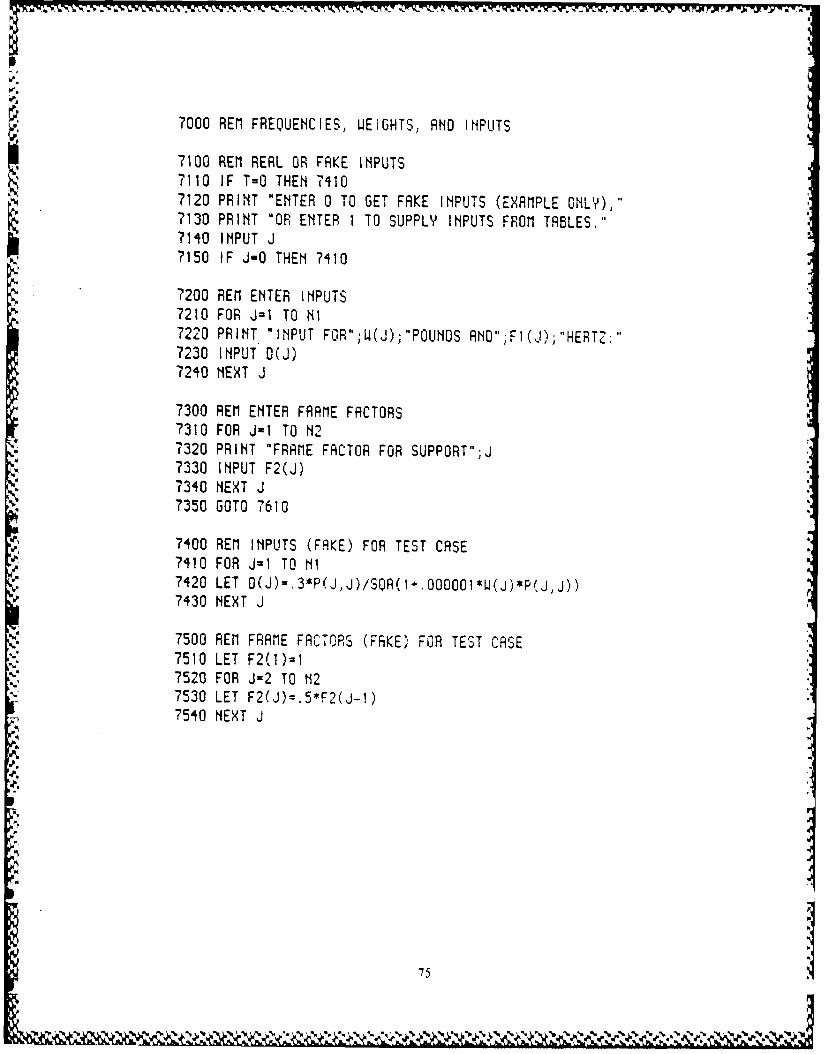
7000 REM FREQUENCIES, WEIGHTS, AND INPUTS
7100 REM REAL OR FAKE INPUTS7110 IF T=O THEN 74107120 PRINT "ENTER 0 TO GET FAKE INPUTS (EXAMPLE ONLY),"7130 PRINT "OR ENTER I TO SUPPLY INPUTS FROM TABLES."7140 INPUT J7150 IF J-0 THEN 7410
7200 REM ENTER INPUTS7210 FOR J=1 TO NI7220 PRINT "INPUT FOR";W(J);"POUNOS ANO";FI(J);"HERTZ:"7230 INPUT D(J)7240 NEXT J
7300 REM ENTER FRAME FACTORS7310 FOR J=1 TO N27320 PRINT "FRAME FACTOR FOR SUPPORT";J7330 INPUT F2(J)7340 NEXT J7350 GOTO 7610
7400 REM INPUTS (FAKE) FOR TEST CASE7410 FOR J=1 TO Ni7420 LET D(J)-.3*P(J,J)/SQR(I .0OOI001EW(J)*P(jJ))7430 NEXT J
7500 REM FRAME FACTORS (FAKE) FOR TEST CASE7510 LET F2(1)=I7520 FOR J=2 TO N27530 LET F2(J)=,5#F2(J-1)7540 NEXT J
751
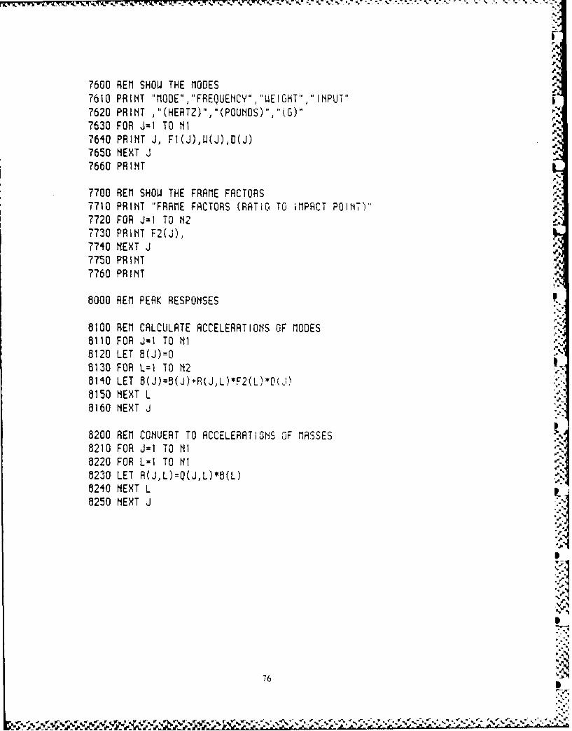
r
7600 REM SHOW THE MODES w7610 PRINT "MODE", FREQUENCY.,'WEIGHT","INPUT"7620 PRINT ,"(HERTZ)'j(POUNDS)','(G)"7630 FOR J=1 TO NI7640 PRINT J, FI(J)1W(J),D(J)7650 NEXT J7660 PRINT
7700 REM SHOW THE FRAME FACTORS7710 PRINT "FRAME FACTORS (RATiG TO iMPACT POINT)"7720 FOR J=1 TO N27730 PRINT F2(J),7740 NEXT J7750 PRINT7760 PRINT
8000 REM PEAK RESPONSES
8100 REM CALCULATE ACCELERATIONS OF MODES8110 FOR J-1 TO NI8120 LET B(J)=O8130 FOR L=I TO N28140 LET 8(J)=B(J)*R(J,L)*F2(L) P(J)8150 NEXT L8160 NEXT J
8200 REM CONUERT TO ACCELERATIONS OF MASSES8210 FOR J=I TO NI8220 FOR L=I TO NI8230 LET A(JL)=Q(J,L)*8(L)8240 NEXT L8250 NEXT J
76
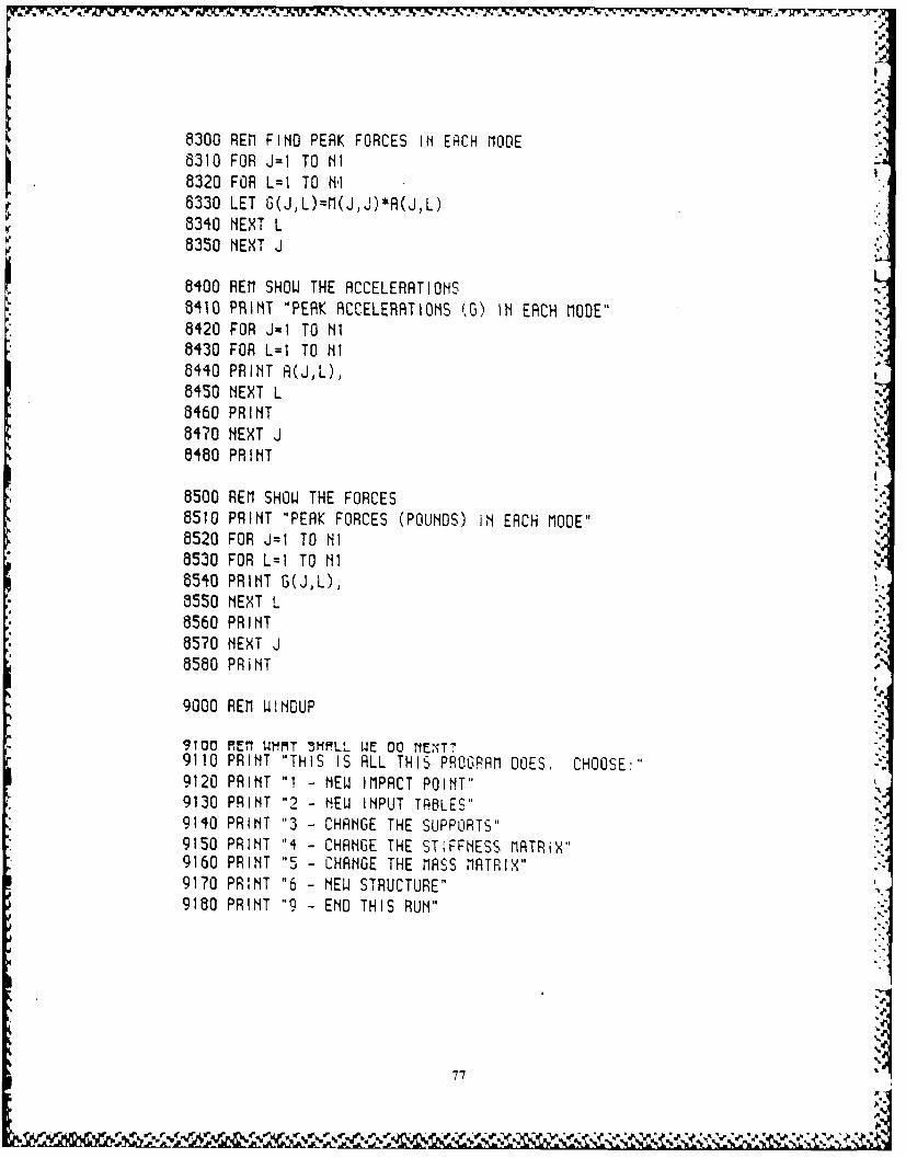
8300 REM FIND PEAK FORCES IN ERCH MODE8310 FOR J=1 TO NI8320 FOR L=l TO NI8330 LET G(J,L)=M(JJ)*A(J,L)8340 NEXT L8350 NEXT J
8400 REM SHOW THE ACCELERATIONS6410 PRINT "PEAK ACCELERATIONS (0) IN EACH MODE"8420 FOR J=1 TO Ni8430 FOR L=1 TO Ni8440 PRINT A(JL),8450 NEXT L8460 PRINT8470 NEXT J6460 PRINT
8500 REM SHOW THE FORCES8510 PRINT "PEAK FORCES (POUNDS) IN EACH MODE"8520 FOR J=1 TO NI8530 FOR L=I TO N18540 PRINT G(JL),8550 NEXT L8560 PRINT8570 NEXT J 5*
8580 PRINTr
9000 REM IJINGUP
9IO REn WMM1T 5MMLL WE DO NENT"9110 PRINT "THIS IS ALL THIS PROGRAM DOES. CHOOSE:'"9120 PRINT "1 - NEW IMPACT POINT"9130 PRINT "2 - NEW INPUT TABLES"9140 PRINT "3 - CHANGE THE SUPPORTS"9150 PRINT "4 - CHANGE THE STIFFNESS MATRIX"9160 PRINT CHANGE THE MASS MATRIX"9170 PRINT "6 - NEW STRUCTURE"9180 PRINT "9 - END THIS RUN"
77
Lie ' % e .
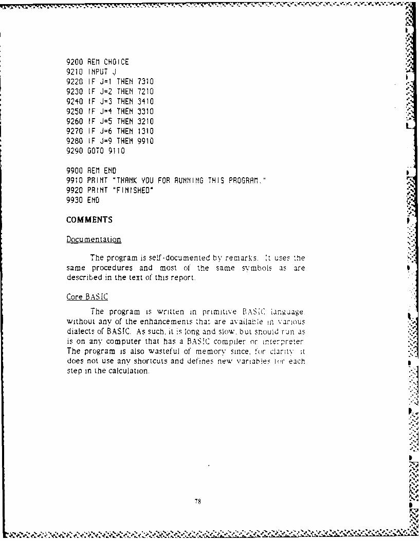
9200 RIEM CHOICE9210 INPUT J9220 IF J=1 THEN 73109230 IF J=2 THEN 72109240 IF J=3 THEN 3410 Pr9250 IF J=4 THEN 33109260 IF J=5 THEN 3210
9270 IF J=6 THEN 13109280 IF J=9 THEN 99109290 GOTO 9110
9900 REM END9910 PRINT "THANK YOU FOR RUNNING THIS PROGRAM."9920 PRINT "FINISHED*9930 END
COMMENTS
Documentation
The program is self -documented by remarks. It uses thesame procedures and most of thte same svmbols as aredescribed in the text of this report.
Core BASIC
The program is written in primitive BASC ianguagewithout any of the enhancements that are availatb.e in variousdialects of BASIC. As such, it is long and slow, but should run asis on any computer that has a BASIC compiler or ir'.erreterThe program is also wasteful of memory since, for clarltv itdoes not use anv shortcuts and defines new variables 1Hr eachstep in the calculation.
.1
78X-11
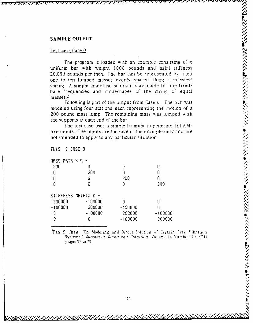
- -. - 77 -7 - .
SAMPLE OUTPUT
Test case, Case 0 J";.y,
The program is loaded with an example consisting of auniform bar with weight 1000 pounds and axial stiffness20,000 pounds per inch. The bar can be represented by fromone to ten lumped masses evenly spaced along a masslessspring. A simple analytical soluuon is available for the fixed-base frequencies and modeshapes of the string o(f equalmasses.2
Following is part of the output from Case 0. The bar vasmodeled using four stations, each representing the motion of a200-pound mass lump. The remaining mass was lumped withthe supports at each end of the bar. .2.
The test case uses a simple formula to generate [DDAM-like inputs. The inputs are for sake of the example only and are 1.not intended to apply to any particular situation.
THIS IS CASE 0
MASS MRTRX M200 0 0 00 200 0 00 0 200 00 0 0 2 0
STIFFNESS MATRIX K =200000 -100000 0 0
-100000 200000 -i00000 0o -100000 200000 -1000000 0 -100000 2n0o00
2Fan Y Chen. "On Modeling and Direct Solution if Certain Free VibrationSystems," Journal ofSound and ;braiwton Volume 14 Number I 191" 1pages 57 to 79
',.
?9 .
9.
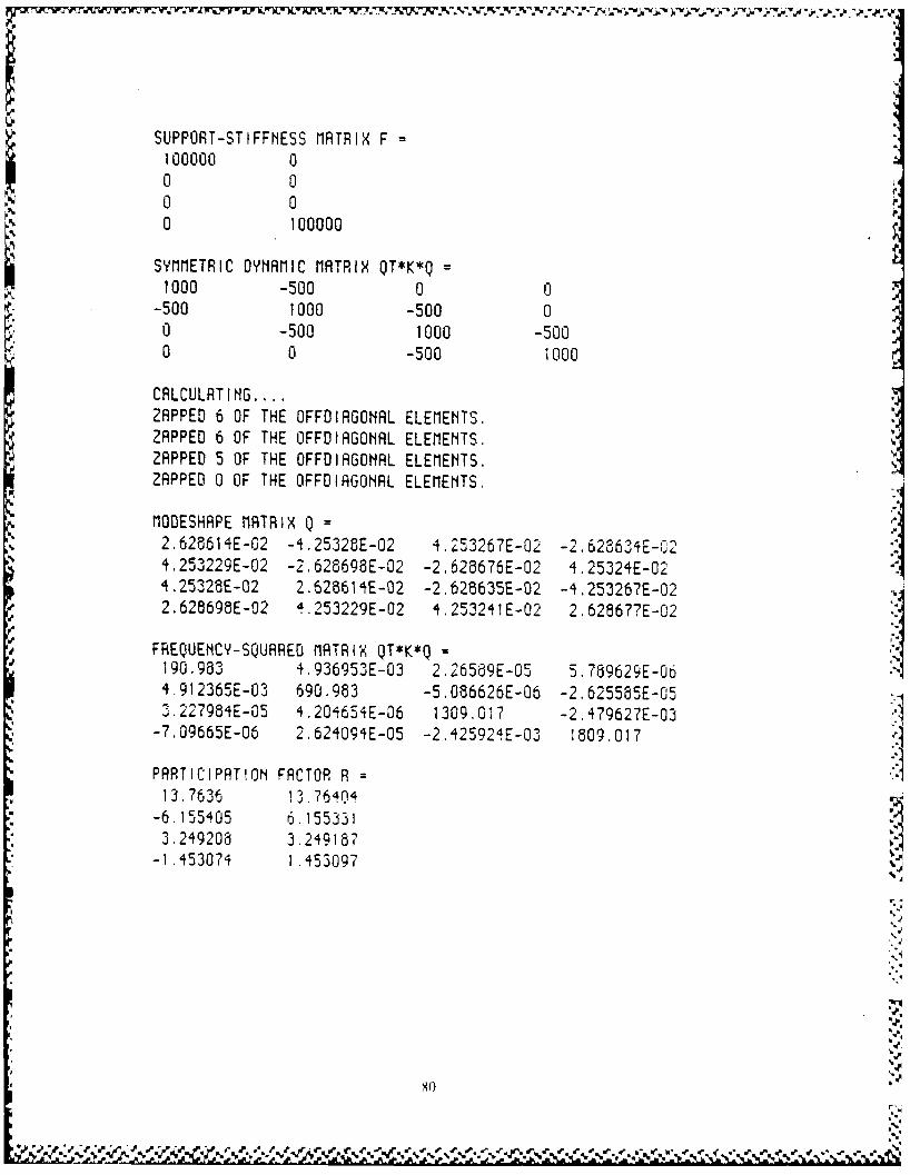
SUPPORT-STIFFNESS MATRIX F =
100000 00 0
SYMMETRIC DYNAMIC MATRIX QT*K*Q=1000 -500 0 a
-500 1000 -500 00 -500 1000 -5000 0 -500 1000
CALCULATING ....ZAPPED 6 OF THE OFFDIAGONAL ELEMENTS.ZAPPED 6 OF THE OFFDIAGONAL ELEMENTS.ZAPPED 5 OF THE OFFDIAGONRL ELEMENTS.ZAPPED 0 OF THE OFFDIAGONAL ELEMENTS.
MODESHAPE MATRIX Q =2,628614E-02 -4.25328E-02 4.253267E-02 -2.6286'34E-024.253229E-02 -2.628698E-02 -2.628676E-02 4.25324E-02' .25328E-02 2.625614E-02 -2.628635E-02 -4.253267E-022.628698E-02 4.253229E-02 4.253241E-02 2.628677E-02
FREQUENCY-SQUARED MATRIX QT*K*Q =190.983 4.936953E-03 2.26569E-05 5.789629E-064.912365E-03 690.983 -5.086626E-06 -2.625585E-053.227984E-05 4.204654E-06 1309.017 -2.479627E-03 -1
-7.09665E-06 2.624094E-05 -2.42592iE-3 1"09.0171
PARTICIPATION FACTOR R =
13,7636 13.76404-6.155405 6.1553313.249208 3.249187
-1.453074 1.453097 A
I,
SOO
.1 W*
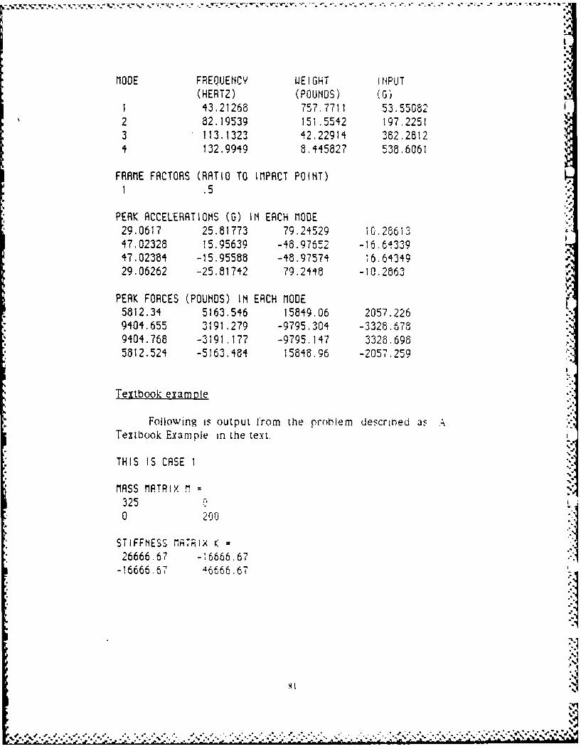
MODE FREQUENCY WEIGHT INPUT(HERTZ) (POUNDS) (G)
1 43.21268 757.7711 53.550822 82.19539 151.5542 197.22513 113.1323 42,22914 362.28124 132.9949 8.445827 538,6061
FRAME FACTORS (RATIO TO IMPACT POINT)1 .5
PEAK ACCELERATIONS (G) IN EACH MODE29.0617 25.81773 79.24529 10,2861347,02328 15,95639 -48,97652 -16.6433947.02384 -15.95588 -48,97574 16.6434929.06262 -25,81742 79,2446 -10.2863
PEAK FORCES (POUNDS) IN ERCH MODE5812.34 5163.546 15849.06 2057.2269404.655 3191.279 -9795.304 -3326.6789404.768 -3191.177 -9795.147 3328.6965812.524 -5163.464 15646.96 -2057.259
Textbook example
Following is output from the problem described as ATextbook Example in the text.
THIS IS CASE I
MASS MATRIX 13250 200
STIFFNESS MATRIX K26666.67 -16666.67-16666.67 46466.67
. . . . . . . . . .. .. ....... ........ ............. ..
, )' .' ' ':-, ' ,7 -'-' ' " • . ". *. * " . . .t*'. "-
' .*' % . **%** ~ h*''.\***I
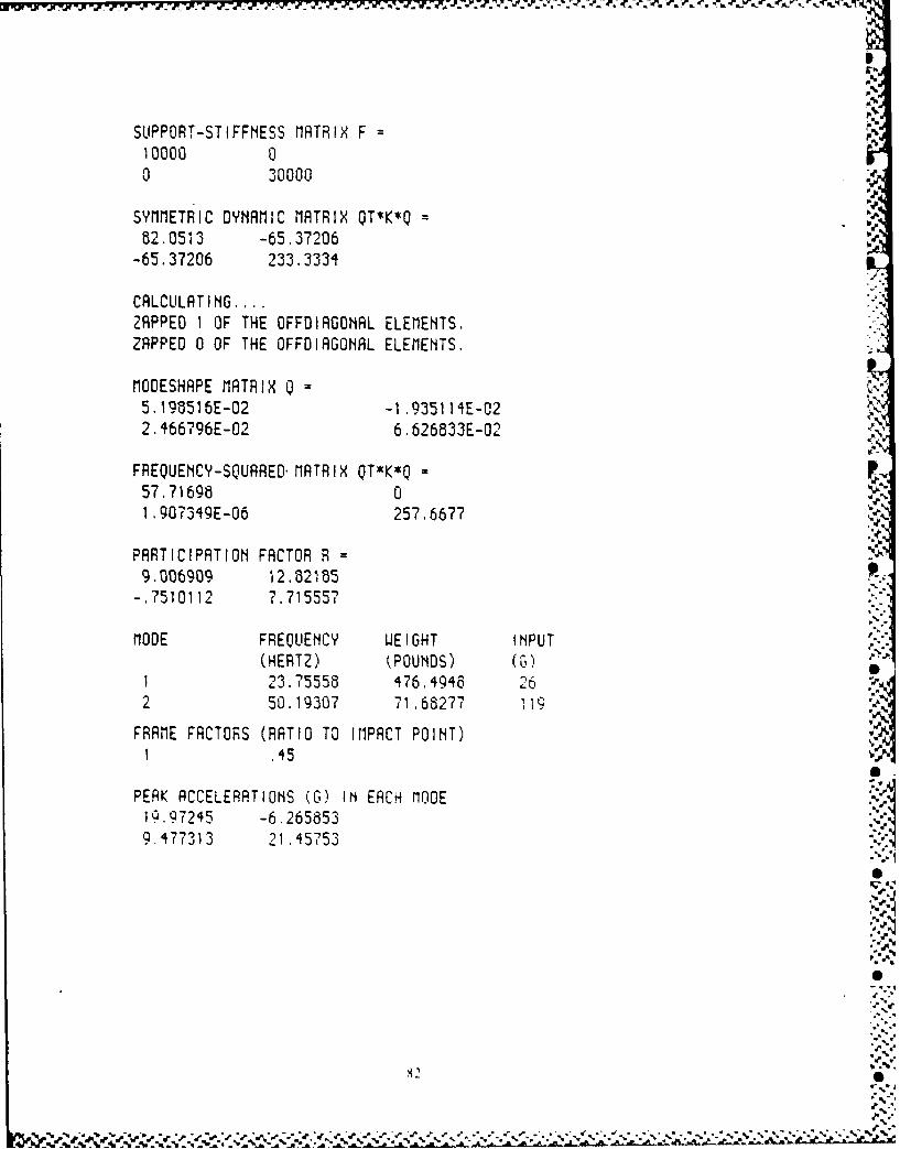
SUPPORT-STIFFNESS MATRIX F10000 00 30000
P,p
SYMMETRIC DYNAM IC MATRIX OT*K*Q =
82.0513 -65.37206 .'.
-65.37206 233. 3334 L
CALCULATING ....ZAPPED 1 OF THE OFFDIAGONAL ELEMENTS.ZAPPED 0 OF THE OFFOIAGONAL ELEMENTS.
MODESHAPE MATRIX Q =
2. 466796E-02 6. 626833E-02
FREQUENCY-SQUARED.79MATRIX QT*K*Q =p57.71698 0%1 ,907349E-06 257.6677
PARTICIPATION FACTOR R = .
9.006909 12.82185-.7510112 7.715557
MODE FREQUENCY WEIGHT INPUT(HERTZ) (POUNDS) (G)
1 23.75558 476.4946 262 50.19307 71.68277 1.19
FRAME FACTORS (RATIO TO I1PACT POINT)1 .45
PERK ACCELERATIONS (G) IN EACH MODEIQ97245 -6.2658539.477313 21.45753
- -- - -S -- •
W , .' .,¢ ,'¢"Z"Z" " "€.-:'' ' - ' % ". " '.'.' "'.'. "'" , . '.'." ." *'. "- "" " "r'.¢' , K.' .. ", -, ; .

5/S
"I'
P~K FORC~ (POUNOg) I~ ~Cw rIQOg6491 .047 -2036.4021895.463 i291.506
S
h%.
A
.d.A
-4
-p.'.4,
-p.
.44-
4,,-p.
p.,.
'4.
-- p
w** ?.4-
4--,
4- "44-
-p...
-p.
p..p
A--'p
4,.~-p
SW."4
4'
4'
4'
83
'V..5.
* '' -- ~ ' '-~--*,.---.. ~ P ~* .$ 4- ~ .~ *' ~ ~ -. .*~ 44* * '***~~ 4,