Embed Size (px)
Citation preview
HEAT TREATMENT OF TOOL STEEL
1
HEAT TREATMENT OF TOOL STEEL

SS-EN ISO 9001SS-EN ISO 14001
This information is based on our present state of knowledge and is intended to provide generalnotes on our products and their uses. It should not therefore be construed as a warranty ofspecific properties of the products described or a warranty for fitness for a particular purpose.
Classified according to EU Directive 1999/45/ECFor further information see our “Material Safety Data Sheets”.
Edition 8, - revised 06.2012, not printedThe latest revised edition of this brochure is the English version,which is always published on our web site www.uddeholm.com
Cover photos from left to right: Böhler Uddeholm Czech Republic,Uddeholms AB/HÄRDtekno, Sweden and Ionbond Sweden AB.

HEAT TREATMENT OF TOOL STEEL
3
CONTENTS
What is tool steel? 4
Hardening and tempering 4
Dimensional and shape stability 11
Surface treatment 12
Testing of mechanical properties 14
Some words of advice to tool designers 15
Hardness after hardening and tempering 17
Hardness conversion table 18
HEAT TREATMENT OF TOOL STEEL
4
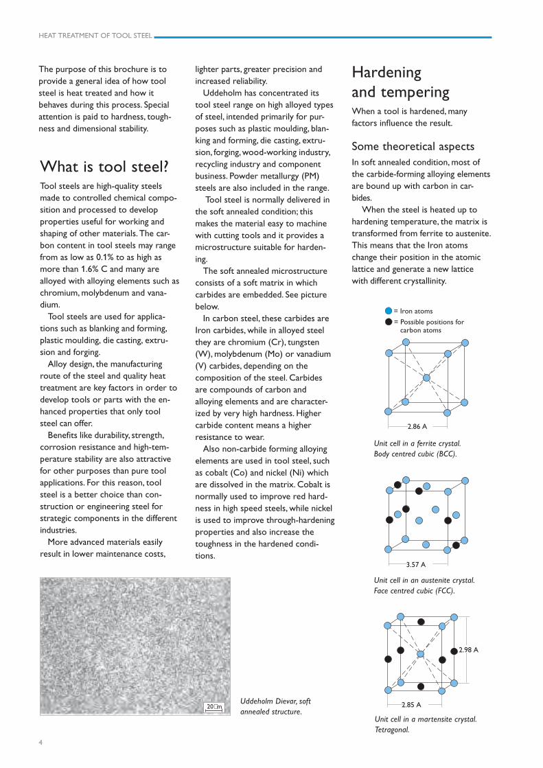
Uddeholm Dievar, softannealed structure.
The purpose of this brochure is toprovide a general idea of how toolsteel is heat treated and how itbehaves during this process. Specialattention is paid to hardness, tough-ness and dimensional stability.
What is tool steel?Tool steels are high-quality steelsmade to controlled chemical compo-sition and processed to developproperties useful for working andshaping of other materials. The car-bon content in tool steels may rangefrom as low as 0.1% to as high asmore than 1.6% C and many arealloyed with alloying elements such aschromium, molybdenum and vana-dium.
Tool steels are used for applica-tions such as blanking and forming,plastic moulding, die casting, extru-sion and forging.
Alloy design, the manufacturingroute of the steel and quality heattreatment are key factors in order todevelop tools or parts with the en-hanced properties that only toolsteel can offer.
Benefits like durability, strength,corrosion resistance and high-tem-perature stability are also attractivefor other purposes than pure toolapplications. For this reason, toolsteel is a better choice than con-struction or engineering steel forstrategic components in the differentindustries.
More advanced materials easilyresult in lower maintenance costs,
Hardeningand temperingWhen a tool is hardened, manyfactors influence the result.
Some theoretical aspectsIn soft annealed condition, most ofthe carbide-forming alloying elementsare bound up with carbon in car-bides.
When the steel is heated up tohardening temperature, the matrix istransformed from ferrite to austenite.This means that the Iron atomschange their position in the atomiclattice and generate a new latticewith different crystallinity.
lighter parts, greater precision andincreased reliability.
Uddeholm has concentrated itstool steel range on high alloyed typesof steel, intended primarily for pur-poses such as plastic moulding, blan-king and forming, die casting, extru-sion, forging, wood-working industry,recycling industry and componentbusiness. Powder metallurgy (PM)steels are also included in the range.
Tool steel is normally delivered inthe soft annealed condition; thismakes the material easy to machinewith cutting tools and it provides amicrostructure suitable for harden-ing.
The soft annealed microstructureconsists of a soft matrix in whichcarbides are embedded. See picturebelow.
In carbon steel, these carbides areIron carbides, while in alloyed steelthey are chromium (Cr), tungsten(W), molybdenum (Mo) or vanadium(V) carbides, depending on thecomposition of the steel. Carbidesare compounds of carbon andalloying elements and are character-ized by very high hardness. Highercarbide content means a higherresistance to wear.
Also non-carbide forming alloyingelements are used in tool steel, suchas cobalt (Co) and nickel (Ni) whichare dissolved in the matrix. Cobalt isnormally used to improve red hard-ness in high speed steels, while nickelis used to improve through-hardeningproperties and also increase thetoughness in the hardened condi-tions.
Unit cell in a martensite crystal.Tetragonal.
20µm
= Possible positions for carbon atoms
= Iron atoms
3.57 A
2.85 A
2.98 A
2.86 A
Unit cell in an austenite crystal.Face centred cubic (FCC).
Unit cell in a ferrite crystal.Body centred cubic (BCC).
HEAT TREATMENT OF TOOL STEEL
5
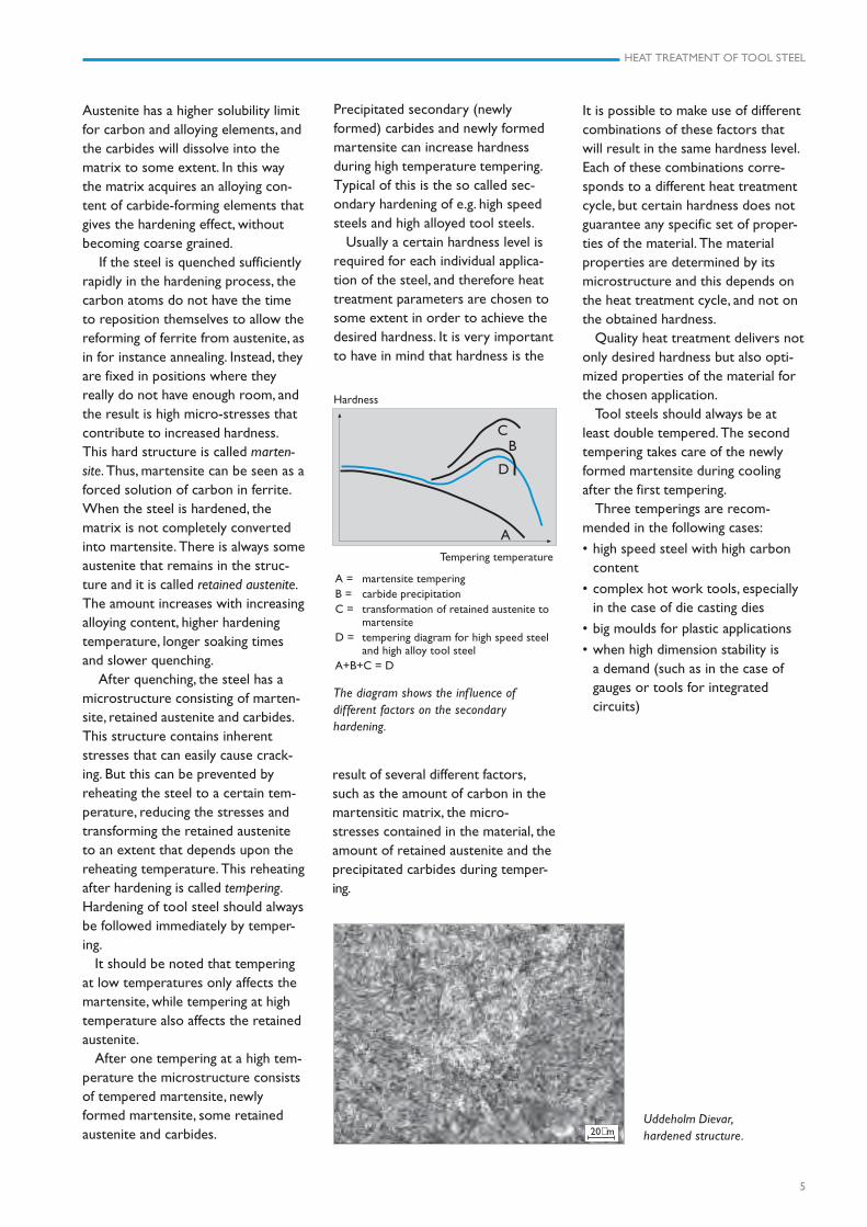
Uddeholm Dievar,hardened structure.
Austenite has a higher solubility limitfor carbon and alloying elements, andthe carbides will dissolve into thematrix to some extent. In this waythe matrix acquires an alloying con-tent of carbide-forming elements thatgives the hardening effect, withoutbecoming coarse grained.
If the steel is quenched sufficientlyrapidly in the hardening process, thecarbon atoms do not have the timeto reposition themselves to allow thereforming of ferrite from austenite, asin for instance annealing. Instead, theyare fixed in positions where theyreally do not have enough room, andthe result is high micro-stresses thatcontribute to increased hardness.This hard structure is called marten-site. Thus, martensite can be seen as aforced solution of carbon in ferrite.When the steel is hardened, thematrix is not completely convertedinto martensite. There is always someaustenite that remains in the struc-ture and it is called retained austenite.The amount increases with increasingalloying content, higher hardeningtemperature, longer soaking timesand slower quenching.
After quenching, the steel has amicrostructure consisting of marten-site, retained austenite and carbides.This structure contains inherentstresses that can easily cause crack-ing. But this can be prevented byreheating the steel to a certain tem-perature, reducing the stresses andtransforming the retained austeniteto an extent that depends upon thereheating temperature. This reheatingafter hardening is called tempering.Hardening of tool steel should alwaysbe followed immediately by temper-ing.
It should be noted that temperingat low temperatures only affects themartensite, while tempering at hightemperature also affects the retainedaustenite.
After one tempering at a high tem-perature the microstructure consistsof tempered martensite, newlyformed martensite, some retainedaustenite and carbides.
Hardness
Tempering temperature
A = martensite temperingB = carbide precipitationC = transformation of retained austenite to
martensiteD = tempering diagram for high speed steel
and high alloy tool steelA+B+C = D
The diagram shows the inf luence ofdifferent factors on the secondaryhardening.
A
D
BC
Precipitated secondary (newlyformed) carbides and newly formedmartensite can increase hardnessduring high temperature tempering.Typical of this is the so called sec-ondary hardening of e.g. high speedsteels and high alloyed tool steels.
Usually a certain hardness level isrequired for each individual applica-tion of the steel, and therefore heattreatment parameters are chosen tosome extent in order to achieve thedesired hardness. It is very importantto have in mind that hardness is the
result of several different factors,such as the amount of carbon in themartensitic matrix, the micro-stresses contained in the material, theamount of retained austenite and theprecipitated carbides during temper-ing.
It is possible to make use of differentcombinations of these factors thatwill result in the same hardness level.Each of these combinations corre-sponds to a different heat treatmentcycle, but certain hardness does notguarantee any specific set of proper-ties of the material. The materialproperties are determined by itsmicrostructure and this depends onthe heat treatment cycle, and not onthe obtained hardness.
Quality heat treatment delivers notonly desired hardness but also opti-mized properties of the material forthe chosen application.
Tool steels should always be atleast double tempered. The secondtempering takes care of the newlyformed martensite during coolingafter the first tempering.
Three temperings are recom-mended in the following cases:
• high speed steel with high carboncontent
• complex hot work tools, especiallyin the case of die casting dies
• big moulds for plastic applications
• when high dimension stability isa demand (such as in the case ofgauges or tools for integratedcircuits)
20µm
HEAT TREATMENT OF TOOL STEEL
6
Stress relievingDistortion due to hardening must betaken into account when a tool isrough machined. Rough machiningcauses thermal and mechanicalstresses that will remain embeddedin the material. This might not besignificant on a symmetrical part ofsimple design, but can be of greatimportance in an asymmetrical andcomplex machining, for example ofone half of a die casting die. Here,stress-relieving heat treatment isalways recommended.
This treatment is done after roughmachining and before hardening andentails heating to 550–700°C (1020–1300°F). The material should beheated until it has achieved a uniformtemperature all the way through,where it remains 2–3 hours and thencooled slowly, for example in a fur-nace. The reason for a necessaryslow cooling is to avoid new stressesof thermal origin in the stress-freematerial.
The idea behind stress relieving isthat the yield strength of the materialat elevated temperatures is so lowthat the material cannot resist thestresses contained in it. The yieldstrength is exceeded and thesestresses are released, resulting in agreater or lesser degree of plasticdeformation.
The excuse that stress relievingtakes too much time is hardly validwhen the potential consequences areconsidered. Rectifying a part duringsemi-finish machining is with few
Heating tohardening temperatureAs has already been explained,stresses contained in the materialwill produce distortion during heattreatment. For this reason, thermalstresses during heating should beavoided.
The fundamental rule for heatingto hardening temperature is there-fore, that it should take place slowly,increasing just a few degrees perminute. In every heat treatment, theheating process is named ramping.The ramping for hardening should bemade in different steps, stopping theprocess at intermediate tempera-tures, commonly named preheatingsteps. The reason for this is to equal-ise the temperatures between thesurface and the centre of the part.Typically choosen preheating tem-peratures are 600–650°C (1100–1200°F) and 800–850°C (1450–1560°F).
In the case of big tools with complexgeometry a third preheating stepclose to the fully austenitic region isrecommended.
Holding time athardening temperatureIt is not possible to briefly state exactrecommendations to cover all heat-ing situations.
Factors such as furnace type, hard-ening temperature, the weight of thecharge in relation to the size of thefurnace, the geometry of the differentparts in the charge, etc., must betaken into consideration in each case.
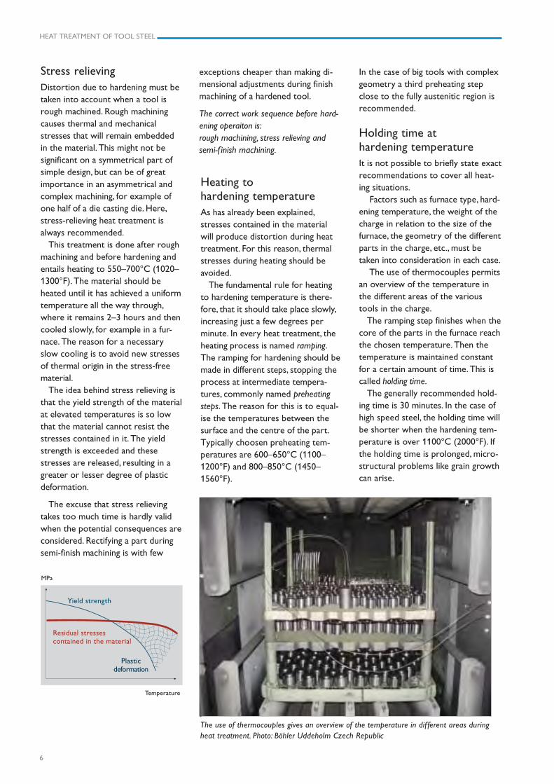
The use of thermocouples permitsan overview of the temperature inthe different areas of the varioustools in the charge.
The ramping step finishes when thecore of the parts in the furnace reachthe chosen temperature. Then thetemperature is maintained constantfor a certain amount of time. This iscalled holding time.
The generally recommended hold-ing time is 30 minutes. In the case ofhigh speed steel, the holding time willbe shorter when the hardening tem-perature is over 1100°C (2000°F). Ifthe holding time is prolonged, micro-structural problems like grain growthcan arise.
.The use of thermocouples gives an overview of the temperature in different areas duringheat treatment. Photo: Böhler Uddeholm Czech Republic
MPa
Temperature
Residual stressescontained in the material
Yield strength
Plasticdeformation
exceptions cheaper than making di-mensional adjustments during finishmachining of a hardened tool.
The correct work sequence before hard-ening operaiton is:rough machining, stress relieving andsemi-f inish machining.
HEAT TREATMENT OF TOOL STEEL
7
Time
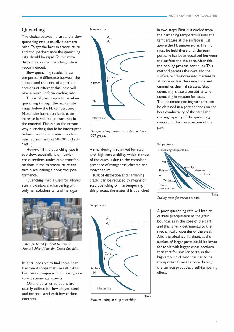
QuenchingThe choice between a fast and a slowquenching rate is usually a compro-mise. To get the best microstructureand tool performance the quenchingrate should be rapid. To minimizedistortion, a slow quenching rate isrecommended.
Slow quenching results in lesstemperature difference between thesurface and the core of a part, andsections of different thickness willhave a more uniform cooling rate.
This is of great importance whenquenching through the martensiterange, below the Ms temperature.Martensite formation leads to anincrease in volume and stresses inthe material. This is also the reasonwhy quenching should be interruptedbefore room temperature has beenreached, normally at 50–70°C (120–160°F).
However, if the quenching rate istoo slow, especially with heaviercross-sections, undesirable transfor-mations in the microstructure cantake place, risking a poor tool per-formance.
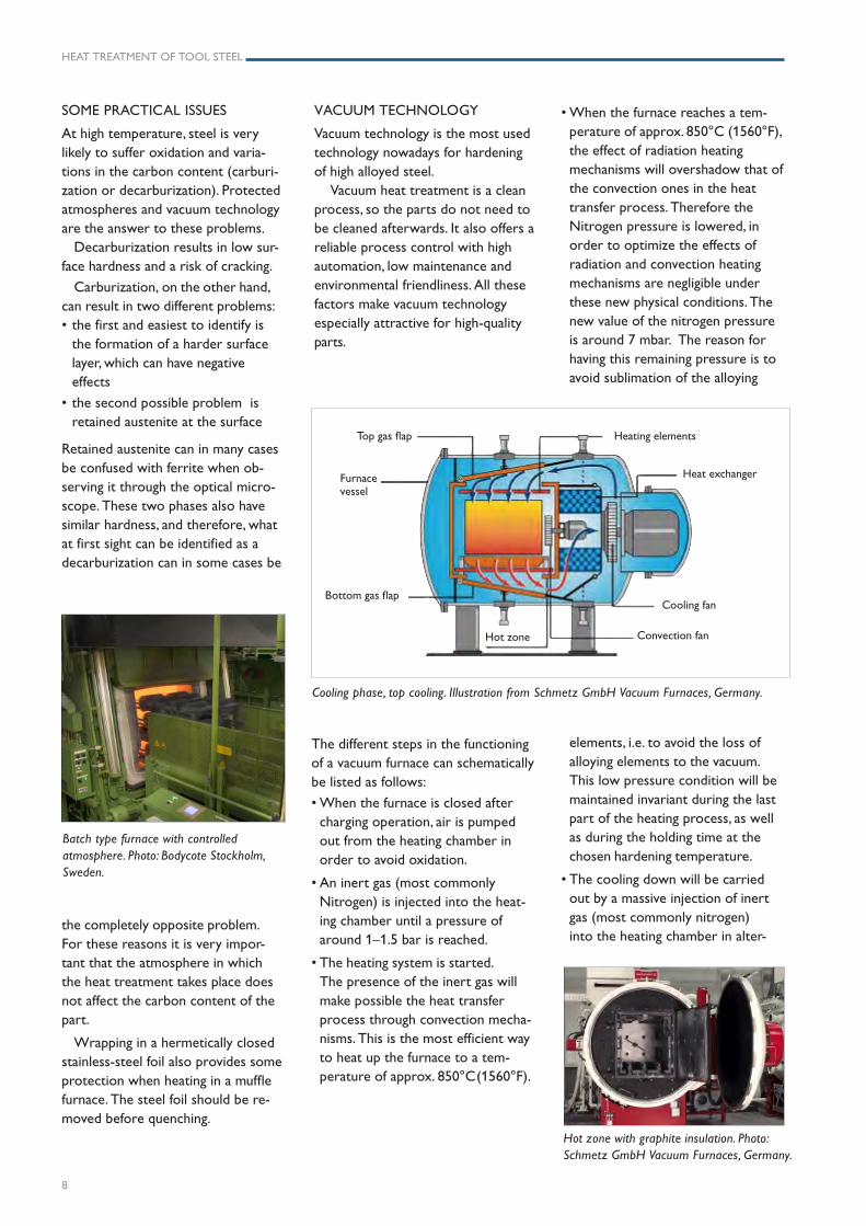
Quenching media used for alloyedsteel nowadays are: hardening oil,polymer solutions, air and inert gas.
Air hardening is reserved for steelwith high hardenability, which in mostof the cases is due to the combinedpresence of manganese, chrome andmolybdenum.
Risk of distortion and hardeningcracks can be reduced by means ofstep quenching or martempering. Inthis process the material is quenched
Martempering or step-quenching.
AC1
AC3
Temperature
Core
MS
Martensite
Surface
The quenching process as expressed in aCCT graph.
Martensite
Core
AC1
AC3
Temperature
Surface
MS
in two steps. First it is cooled fromthe hardening temperature until thetemperature at the surface is justabove the Ms
temperature. Then itmust be held there until the tem-perature has been equalised betweenthe surface and the core. After this,the cooling process continues. Thismethod permits the core and thesurface to transform into martensiteat more or less the same time anddiminishes thermal stresses. Stepquenching is also a possibility whenquenching in vacuum furnaces.The maximum cooling rate that canbe obtained in a part depends on theheat conductivity of the steel, thecooling capacity of the quenchingmedia and the cross-section of thepart.
Cooling rates for various media.
A poor quenching rate will lead tocarbide precipitation at the grainboundaries in the core of the part,and this is very detrimental to themechanical properties of the steel.Also the obtained hardness at thesurface of larger parts could be lowerfor tools with bigger cross-sectionsthan that for smaller parts, as thehigh amount of heat that has to betransported from the core throughthe surface produces a self-temperingeffect.
It is still possible to find some heattreatment shops that use salt baths,but this technique is disappearing dueto environmental aspects.
Oil and polymer solutions areusually utilised for low alloyed steeland for tool steel with low carboncontents.
Batch prepared for heat treatment.Photo: Böhler Uddeholm Czech Republic.
MS
Hardening temperature
Roomtemperature
Oil
Temperature
Air
Salt bath
Time
Vacuum
Water
Polymer
HEAT TREATMENT OF TOOL STEEL
8
VACUUM TECHNOLOGY
Vacuum technology is the most usedtechnology nowadays for hardeningof high alloyed steel.
Vacuum heat treatment is a cleanprocess, so the parts do not need tobe cleaned afterwards. It also offers areliable process control with highautomation, low maintenance andenvironmental friendliness. All thesefactors make vacuum technologyespecially attractive for high-qualityparts.
The different steps in the functioningof a vacuum furnace can schematicallybe listed as follows:
• When the furnace is closed aftercharging operation, air is pumpedout from the heating chamber inorder to avoid oxidation.
• An inert gas (most commonlyNitrogen) is injected into the heat-ing chamber until a pressure ofaround 1–1.5 bar is reached.
• The heating system is started.The presence of the inert gas willmake possible the heat transferprocess through convection mecha-nisms. This is the most efficient wayto heat up the furnace to a tem-perature of approx. 850°C(1560°F).
SOME PRACTICAL ISSUES
At high temperature, steel is verylikely to suffer oxidation and varia-tions in the carbon content (carburi-zation or decarburization). Protectedatmospheres and vacuum technologyare the answer to these problems.
Decarburization results in low sur-face hardness and a risk of cracking.
Carburization, on the other hand,can result in two different problems:• the first and easiest to identify is
the formation of a harder surfacelayer, which can have negativeeffects
• the second possible problem isretained austenite at the surface
Retained austenite can in many casesbe confused with ferrite when ob-serving it through the optical micro-scope. These two phases also havesimilar hardness, and therefore, whatat first sight can be identified as adecarburization can in some cases be
the completely opposite problem.For these reasons it is very impor-tant that the atmosphere in whichthe heat treatment takes place doesnot affect the carbon content of thepart.
Wrapping in a hermetically closedstainless-steel foil also provides someprotection when heating in a mufflefurnace. The steel foil should be re-moved before quenching.
Batch type furnace with controlledatmosphere. Photo: Bodycote Stockholm,Sweden.
Hot zone with graphite insulation. Photo:Schmetz GmbH Vacuum Furnaces, Germany.
• When the furnace reaches a tem-perature of approx. 850°C (1560°F),the effect of radiation heatingmechanisms will overshadow that ofthe convection ones in the heattransfer process. Therefore theNitrogen pressure is lowered, inorder to optimize the effects ofradiation and convection heatingmechanisms are negligible underthese new physical conditions. Thenew value of the nitrogen pressureis around 7 mbar. The reason forhaving this remaining pressure is toavoid sublimation of the alloying
elements, i.e. to avoid the loss ofalloying elements to the vacuum.This low pressure condition will bemaintained invariant during the lastpart of the heating process, as wellas during the holding time at thechosen hardening temperature.
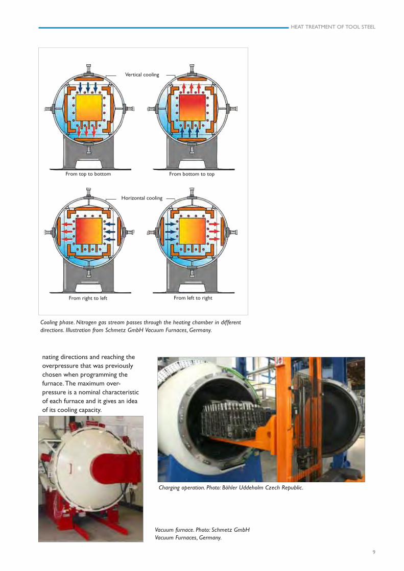
• The cooling down will be carriedout by a massive injection of inertgas (most commonly nitrogen)into the heating chamber in alter-
Cooling phase, top cooling. Illustration from Schmetz GmbH Vacuum Furnaces, Germany.
Heating elements
Cooling fan
Convection fanHot zone
Bottom gas flap
Furnacevessel
Heat exchanger
Top gas flap
HEAT TREATMENT OF TOOL STEEL
9
Cooling phase. Nitrogen gas stream passes through the heating chamber in differentdirections. Illustration from Schmetz GmbH Vacuum Furnaces, Germany.
Vertical cooling
Horizontal cooling
From top to bottom From bottom to top
From right to left From left to right
Charging operation. Photo: Böhler Uddeholm Czech Republic.
nating directions and reaching theoverpressure that was previouslychosen when programming thefurnace. The maximum over-pressure is a nominal characteristicof each furnace and it gives an ideaof its cooling capacity.
Vacuum furnace. Photo: Schmetz GmbHVacuum Furnaces, Germany.
HEAT TREATMENT OF TOOL STEEL
10
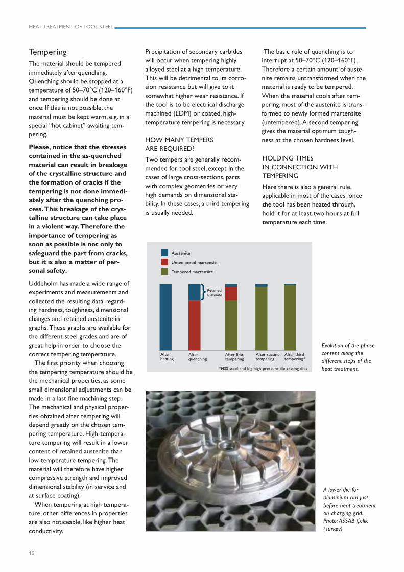
Austenite
Untempered martensite
Tempered martensite
Afterheating
Afterquenching
After firsttempering
After secondtempering
After thirdtempering*
*HSS steel and big high-pressure die casting dies
HOLDING TIMESIN CONNECTION WITHTEMPERING
Here there is also a general rule,applicable in most of the cases: oncethe tool has been heated through,hold it for at least two hours at fulltemperature each time.
Evolution of the phasecontent along thedifferent steps of theheat treatment.
TemperingThe material should be temperedimmediately after quenching.Quenching should be stopped at atemperature of 50–70°C (120–160°F)and tempering should be done atonce. If this is not possible, thematerial must be kept warm, e.g. in aspecial “hot cabinet” awaiting tem-pering.
Please, notice that the stressescontained in the as-quenchedmaterial can result in breakageof the crystalline structure andthe formation of cracks if thetempering is not done immedi-ately after the quenching pro-cess. This breakage of the crys-talline structure can take placein a violent way. Therefore theimportance of tempering assoon as possible is not only tosafeguard the part from cracks,but it is also a matter of per-sonal safety.
Uddeholm has made a wide range ofexperiments and measurements andcollected the resulting data regard-ing hardness, toughness, dimensionalchanges and retained austenite ingraphs. These graphs are available forthe different steel grades and are ofgreat help in order to choose thecorrect tempering temperature.
The first priority when choosingthe tempering temperature should bethe mechanical properties, as somesmall dimensional adjustments can bemade in a last fine machining step.The mechanical and physical proper-ties obtained after tempering willdepend greatly on the chosen tem-pering temperature. High-tempera-ture tempering will result in a lowercontent of retained austenite thanlow-temperature tempering. Thematerial will therefore have highercompressive strength and improveddimensional stability (in service andat surface coating).
When tempering at high tempera-ture, other differences in propertiesare also noticeable, like higher heatconductivity.
Precipitation of secondary carbideswill occur when tempering highlyalloyed steel at a high temperature.This will be detrimental to its corro-sion resistance but will give to itsomewhat higher wear resistance. Ifthe tool is to be electrical dischargemachined (EDM) or coated, high-temperature tempering is necessary.
HOW MANY TEMPERSARE REQUIRED?
Two tempers are generally recom-mended for tool steel, except in thecases of large cross-sections, partswith complex geometries or veryhigh demands on dimensional sta-bility. In these cases, a third temperingis usually needed.
The basic rule of quenching is tointerrupt at 50–70°C (120–160°F).Therefore a certain amount of auste-nite remains untransformed when thematerial is ready to be tempered.When the material cools after tem-pering, most of the austenite is trans-formed to newly formed martensite(untempered). A second temperinggives the material optimum tough-ness at the chosen hardness level.
A lower die foraluminium rim justbefore heat treatmenton charging grid.Photo: ASSAB Çelik(Turkey)
Retainedaustenite}
HEAT TREATMENT OF TOOL STEEL
11
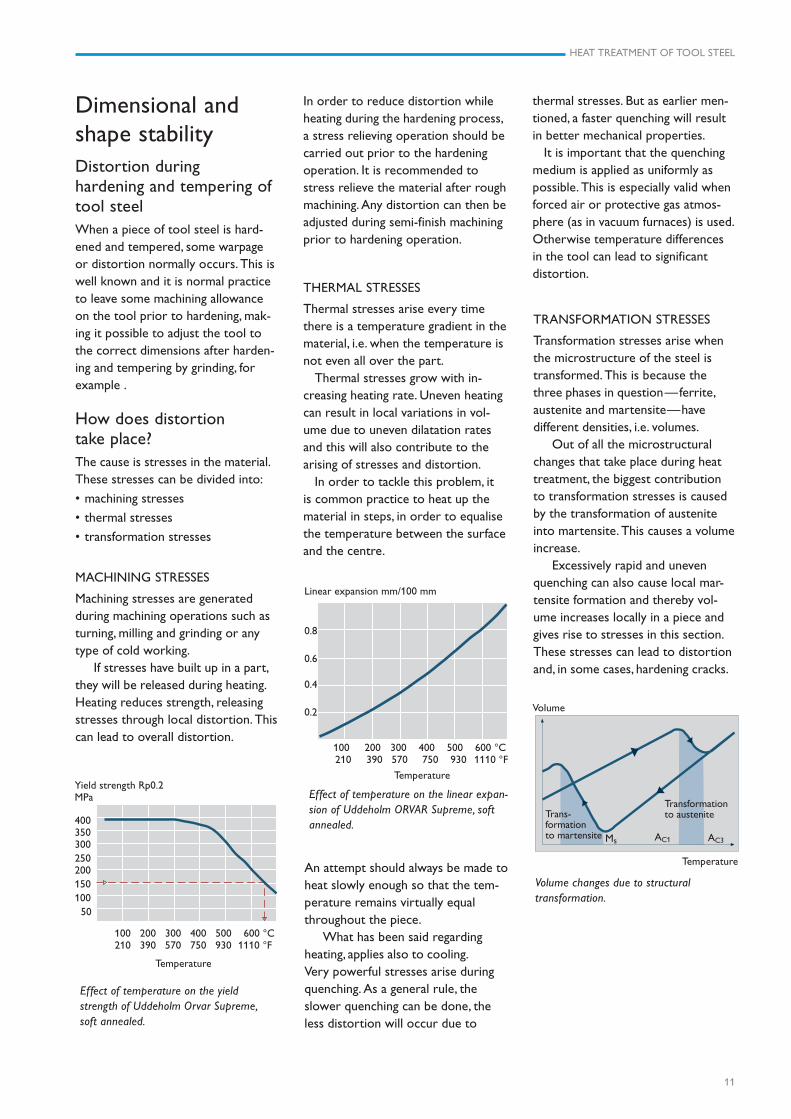
Yield strength Rp0.2MPa
400350300250200150100 50
THERMAL STRESSES
Thermal stresses arise every timethere is a temperature gradient in thematerial, i.e. when the temperature isnot even all over the part.
Thermal stresses grow with in-creasing heating rate. Uneven heatingcan result in local variations in vol-ume due to uneven dilatation ratesand this will also contribute to thearising of stresses and distortion.
In order to tackle this problem, itis common practice to heat up thematerial in steps, in order to equalisethe temperature between the surfaceand the centre.
Linear expansion mm/100 mm
0.8
0.6
0.4
0.2
Effect of temperature on the linear expan-sion of Uddeholm ORVAR Supreme, softannealed.
Dimensional andshape stabilityDistortion duringhardening and tempering oftool steelWhen a piece of tool steel is hard-ened and tempered, some warpageor distortion normally occurs. This iswell known and it is normal practiceto leave some machining allowanceon the tool prior to hardening, mak-ing it possible to adjust the tool tothe correct dimensions after harden-ing and tempering by grinding, forexample .
How does distortiontake place?The cause is stresses in the material.These stresses can be divided into:
• machining stresses
• thermal stresses
• transformation stresses
MACHINING STRESSES
Machining stresses are generatedduring machining operations such asturning, milling and grinding or anytype of cold working.
If stresses have built up in a part,they will be released during heating.Heating reduces strength, releasingstresses through local distortion. Thiscan lead to overall distortion.
100 200 300 400 500 600 °C 210 390 570 750 930 1110 °F
100 200 300 400 500 600 °C 210 390 570 750 930 1110 °F
Temperature
Temperature
An attempt should always be made toheat slowly enough so that the tem-perature remains virtually equalthroughout the piece.
What has been said regardingheating, applies also to cooling.Very powerful stresses arise duringquenching. As a general rule, theslower quenching can be done, theless distortion will occur due to
Transformationto austenite
Volume changes due to structuraltransformation.
Volume
Ms AC1 AC3
Temperature
Trans-formationto martensite
thermal stresses. But as earlier men-tioned, a faster quenching will resultin better mechanical properties.
It is important that the quenchingmedium is applied as uniformly aspossible. This is especially valid whenforced air or protective gas atmos-phere (as in vacuum furnaces) is used.Otherwise temperature differencesin the tool can lead to significantdistortion.
TRANSFORMATION STRESSES
Transformation stresses arise whenthe microstructure of the steel istransformed. This is because thethree phases in question—ferrite,austenite and martensite—havedifferent densities, i.e. volumes.
Out of all the microstructuralchanges that take place during heattreatment, the biggest contributionto transformation stresses is causedby the transformation of austeniteinto martensite. This causes a volumeincrease.
Excessively rapid and unevenquenching can also cause local mar-tensite formation and thereby vol-ume increases locally in a piece andgives rise to stresses in this section.These stresses can lead to distortionand, in some cases, hardening cracks.
In order to reduce distortion whileheating during the hardening process,a stress relieving operation should becarried out prior to the hardeningoperation. It is recommended tostress relieve the material after roughmachining. Any distortion can then beadjusted during semi-finish machiningprior to hardening operation.
Effect of temperature on the yieldstrength of Uddeholm Orvar Supreme,soft annealed.
HEAT TREATMENT OF TOOL STEEL
12
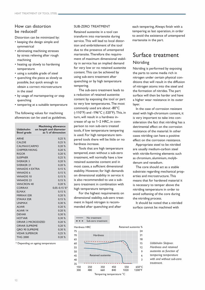
Uddeholm Sleipner.Hardness and retainedaustenite as function oftempering temperaturewith and without sub-zerotreatment.
How can distortionbe reduced?Distortion can be minimized by:• keeping the design simple and
symmetrical• eliminating machining stresses
by stress relieving after roughmachining
• heating up slowly to hardeningtemperature
• using a suitable grade of steel• quenching the piece as slowly as
possible, but quick enough toobtain a correct microstructurein the steel
• by usage of martempering or stepquenching
• tempering at a suitable temperature
The following values for machiningallowances can be used as guidelines.
Machining allowanceUddeholm on length and diameterSteel grade as % of dimension
ARNE 0,25 %CALDIE 0,25 %CALMAX/CARMO 0,20 %CHIPPER/VIKING 0,20 %
RIGOR 0,20 %SLEIPNER 0,25 %SVERKER 3 0,20 %
SVERKER 21 0,20 %VANADIS 4 EXTRA 0,15 %VANADIS 6 0,15 %
VANADIS 10 0,15 %VANADIS 23 0,15 %VANCRON 40 0,20 %
CORRAX 0,05–0,15 %*ELMAX 0,15 %MIRRAX ESR 0,20 %
STAVAX ESR 0,15 %UNIMAX 0,30 %ALVAR 0.20 %
ALVAR 14 0.20 %DIEVAR 0,30 %HOTVAR 0,30 %
ORVAR 2 MICRODIZED 0,20 %ORVAR SUPREME 0,20 %QRO 90 SUPREME 0,30 %
VIDAR SUPERIOR 0,25 %THG 2000 0.20 %
* Depending on ageing temperature
Surface treatmentNitridingNitriding is performed by exposingthe parts to some media rich innitrogen under certain physical con-ditions that will result in the diffusionof nitrogen atoms into the steel andthe formation of nitrides. The partsurface will then be harder and havea higher wear resistance in its outerlayer.
In the case of corrosion resistantsteel with high-chromium content, itis very important to take into con-sideration the fact that nitriding has adetrimental effect on the corrosionresistance of the material. In othercases nitriding can have a positiveeffect on the corrosion resistance.
Appropriate steel to be nitridedare usually medium-carbon steelwith nitride-forming elements suchas chromium, aluminium, molyb-denum and vanadium.
The core should act as a stablesubstrate regarding mechanical prop-erties and microstructure. Thismeans that for hardened material itis necessary to temper above thenitriding temperature in order toavoid softening of the core duringthe nitriding process.
It should be noted that a nitridedsurface cannot be machined with
SUB-ZERO TREATMENT
Retained austenite in a tool cantransform into martensite duringservice. This will lead to local distor-tion and embrittlement of the tooldue to the presence of untemperedmartensite. Therefore the require-ment of maximum dimensional stabil-ity in service has an implied demandfor very low or no retained austenitecontent. This can be achieved byusing sub-zero treatment afterquenching or by high temperaturetempering.
The sub-zero treatment leads toa reduction of retained austenitecontent by exposing the tool or partto very low temperatures. The mostcommonly used are about -80°C(-110°F) and -196°C (-320°F). This, inturn, will result in a hardness in-crease of up to 1–2 HRC, in com-parison to non sub-zero treatedtools, if low temperature temperingis used. For high temperature tem-pered tools there will be little or nohardness increase.
Tools that are high temperaturetempered, even without a sub-zerotreatment, will normally have a lowretained austenite content and inmost cases, a sufficient dimensionalstability. However, for high demandson dimensional stability in service itis also recommended to use a sub-zero treatment in combination withhigh temperature tempering.
For the highest requirements ondimensional stability, sub-zero treat-ment in liquid nitrogen is recom-mended after quenching and after
150 250 350 450 550 650°C300 480 660 840 1020 1200°F
Tempering temperature °C
Hardness
Retained austenite
No treatmentSub-zero treatment
Hardness HRC
75
70
65
60
55
50
45
40
35
Retained austenite %
24
21
18
15
12
9
6
3
each tempering, Always finish with atempering as last operation, in orderto avoid the existence of untemperedmartensite in the part.
HEAT TREATMENT OF TOOL STEEL
13
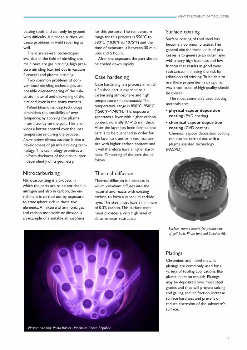
Surface coated mould for productionof golf balls. Photo Ionbond Sweden AB.
NitrocarburizingNitrocarburizing is a process inwhich the parts are to be enriched innitrogen and also in carbon, the en-richment is carried out by exposureto atmosphere rich in these twoelements. A mixture of ammonia gasand carbon monoxide or dioxide isan example of a suitable atmosphere
cutting tools and can only be groundwith difficulty. A nitrided surface willcause problems in weld repairing aswell.
There are several technologiesavailable in the field of nitriding; themain ones are gas nitriding, high pres-sure nitriding (carried out in vacuumfurnaces) and plasma nitriding.
Two common problems of con-ventional nitriding technologies arepossible over-tempering of the sub-strate material and thickening of thenitrided layer in the sharp corners.
Pulsed plasma nitriding technologydiminishes the possibility of over-tempering by applying the plasmaintermittently on the part. This pro-vides a better control over the localtemperatures during the process.Active screen plasma nitriding is also adevelopment of plasma nitriding tech-nology. This technology promises auniform thickness of the nitride layerindependently of its geometry.
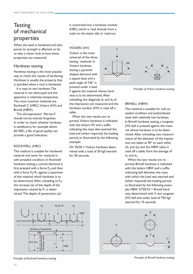
Plasma nitriding. Photo Böhler Uddeholm Czech Republic.
Case hardeningCase hardening is a process in whicha finished part is exposed to acarburizing atmosphere and hightemperature simultaneously. Thetemperature range is 850°C–950°C(1560°F–1740°F). This exposuregenerates a layer with higher carboncontent, normally 0.1–1.5 mm thick.After the layer has been formed, thepart is to be quenched in order forthe layer to transform into marten-site with higher carbon content, andit will therefore have a higher hard-ness. Tempering of the part shouldfollow.
Thermal diffusionThermal diffusion is a process inwhich vanadium diffuses into thematerial and reacts with existingcarbon, to form a vanadium carbidelayer. The steel must have a minimumof 0.3% carbon. This surface treat-ment provides a very high level ofabrasive wear resistance.
Surface coatingSurface coating of tool steel hasbecome a common practise. Thegeneral aim for these kinds of pro-cesses is to generate an outer layerwith a very high hardness and lowfriction that results in good wearresistance, minimising the risk foradhesion and sticking. To be able touse these properties in an optimalway a tool steel of high quality shouldbe chosen.
The most commonly used coatingmethods are:
• physical vapour depositioncoating (PVD coating)
• chemical vapour depositioncoating (CVD coating)Chemical vapour deposition coatingcan also be carried out with aplasma assisted technology
(PACVD)
for this purpose. The temperaturerange for this process is 550°C to580°C (1020°F to 1075°F) and thetime of exposure is between 30 min-utes and 5 hours.
After the exposure the part shouldbe cooled down rapidly.
PlatingsChromium and nickel metallicplatings are commonly used for avariety of tooling applications, likeplastic injection moulds. Platingsmay be deposited over most steelgrades and they will prevent seizingand galling, reduce friction, increasesurface hardness and prevent orreduce corrosion of the substrate’ssurface.
HEAT TREATMENT OF TOOL STEEL
14
F0+F1=FF0 F0
h0 h e HRC
Surface of specimen
HRCh
h0
e
100
0
Har
dnes
s sc
ale
0,2 mm
D
F
d
h
Testingof mechanicalpropertiesWhen the steel is hardened and tem-pered, its strength is affected, so letus take a closer look at how theseproperties are measured.
Hardness testingHardness testing is the most popularway to check the results of hardening.Hardness is usually the property thatis specified when a tool is hardened.
It is easy to test hardness. Thematerial is not destroyed and theapparatus is relatively inexpensive.The most common methods areRockwell C (HRC), Vickers (HV) andBrinell (HBW).
The old expression “file-hard”should not be entirely forgotten.In order to check whether hardnessis satisfactory, for example above60 HRC, a file of good quality canprovide a good indication.
ROCKWELL (HRC)
This method is suitable for hardenedmaterial and never for material insoft annealed condition. In Rockwellhardness testing, a conical diamond isfirst pressed with a force F0, and thenwith a force F0+F1 against a specimenof the material which hardness is tobe determined. After unloading to F0,the increase (e) of the depth of theimpression caused by F1 is deter-mined. The depth of penetration (e)
Principle of Rockwell hardness testing.
BRINELL (HBW)
This method is suitable for soft an-nealed condition and prehardenedsteel with relatively low hardness.In Brinell hardness testing, a tungsten(W) ball is pressed against the mate-rial whose hardness is to be deter-mined. After unloading, two measure-ments of the diameter of the impres-sion are taken at 90° to each other(d1 and d2) and the HBW value isread off a table, from the average ofd1 and d2.
When the test results are re-ported, Brinell hardness is indicatedwith the letters HBW and a suffixindicating ball diameter, the masswith which the load was exerted and(when required) the loading period,as illustrated by the following exam-ple: HBW 5/750/15 = Brinell hard-ness determined with 5 mm tungsten(W) ball and under load of 750 kgfexerted for 15 seconds.
Principle of Brinell hardness testing.
F
136°
d2d
1
Principle of Vickers hardness testing.
is converted into a hardness number(HRC) which is read directly from ascale on the tester dial or read-out.
VICKERS (HV)
Vickers is the mostuniversal of the threetesting methods. InVickers hardnesstesting a pyramid-shaped diamond witha square base and apeak angle of 136° ispressed under a loadF against the material whose hard-ness is to be determined. Afterunloading, the diagonals d1 and d2 ofthe impression are measured and thehardness number (HV) is read off atable.
When the test results are re-ported, Vickers hardness is indicatedwith the letters HV and a suffixindicating the mass that exerted theload and (when required) the loadingperiod, as illustrated by the followingexample:
HV 30/20 = Vickers hardness deter-mined with a load of 30 kgf exertedfor 20 seconds.
HEAT TREATMENT OF TOOL STEEL
15
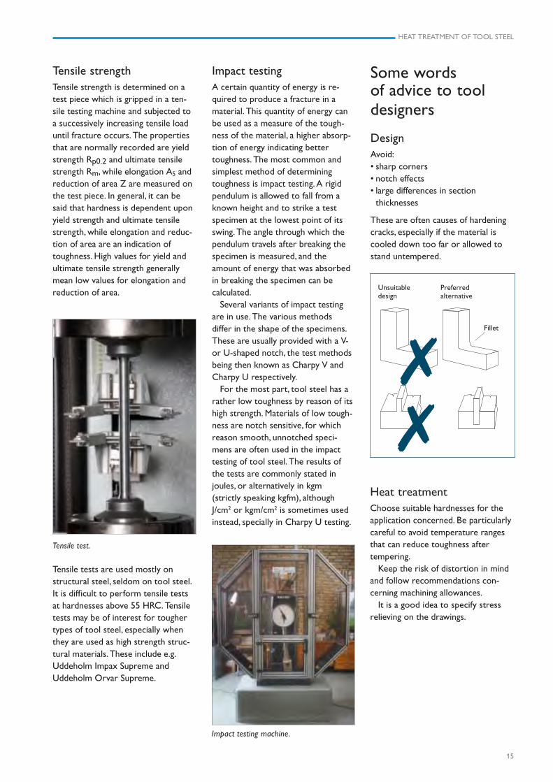
Tensile strengthTensile strength is determined on atest piece which is gripped in a ten-sile testing machine and subjected toa successively increasing tensile loaduntil fracture occurs. The propertiesthat are normally recorded are yieldstrength Rp0.2 and ultimate tensilestrength Rm, while elongation A5 andreduction of area Z are measured onthe test piece. In general, it can besaid that hardness is dependent uponyield strength and ultimate tensilestrength, while elongation and reduc-tion of area are an indication oftoughness. High values for yield andultimate tensile strength generallymean low values for elongation andreduction of area.
Heat treatmentChoose suitable hardnesses for theapplication concerned. Be particularlycareful to avoid temperature rangesthat can reduce toughness aftertempering.
Keep the risk of distortion in mindand follow recommendations con-cerning machining allowances.
It is a good idea to specify stressrelieving on the drawings.
Some wordsof advice to tooldesigners
DesignAvoid:• sharp corners• notch effects• large differences in section
thicknesses
These are often causes of hardeningcracks, especially if the material iscooled down too far or allowed tostand untempered.
Unsuitabledesign
Preferredalternative
✗✗
Fillet
Impact testingA certain quantity of energy is re-quired to produce a fracture in amaterial. This quantity of energy canbe used as a measure of the tough-ness of the material, a higher absorp-tion of energy indicating bettertoughness. The most common andsimplest method of determiningtoughness is impact testing. A rigidpendulum is allowed to fall from aknown height and to strike a testspecimen at the lowest point of itsswing. The angle through which thependulum travels after breaking thespecimen is measured, and theamount of energy that was absorbedin breaking the specimen can becalculated.
Several variants of impact testingare in use. The various methodsdiffer in the shape of the specimens.These are usually provided with a V-or U-shaped notch, the test methodsbeing then known as Charpy V andCharpy U respectively.
For the most part, tool steel has arather low toughness by reason of itshigh strength. Materials of low tough-ness are notch sensitive, for whichreason smooth, unnotched speci-mens are often used in the impacttesting of tool steel. The results ofthe tests are commonly stated injoules, or alternatively in kgm(strictly speaking kgfm), althoughJ/cm2 or kgm/cm2 is sometimes usedinstead, specially in Charpy U testing.
Tensile tests are used mostly onstructural steel, seldom on tool steel.It is difficult to perform tensile testsat hardnesses above 55 HRC. Tensiletests may be of interest for toughertypes of tool steel, especially whenthey are used as high strength struc-tural materials. These include e.g.Uddeholm Impax Supreme andUddeholm Orvar Supreme.
Impact testing machine.
Tensile test.
HEAT TREATMENT OF TOOL STEEL
16
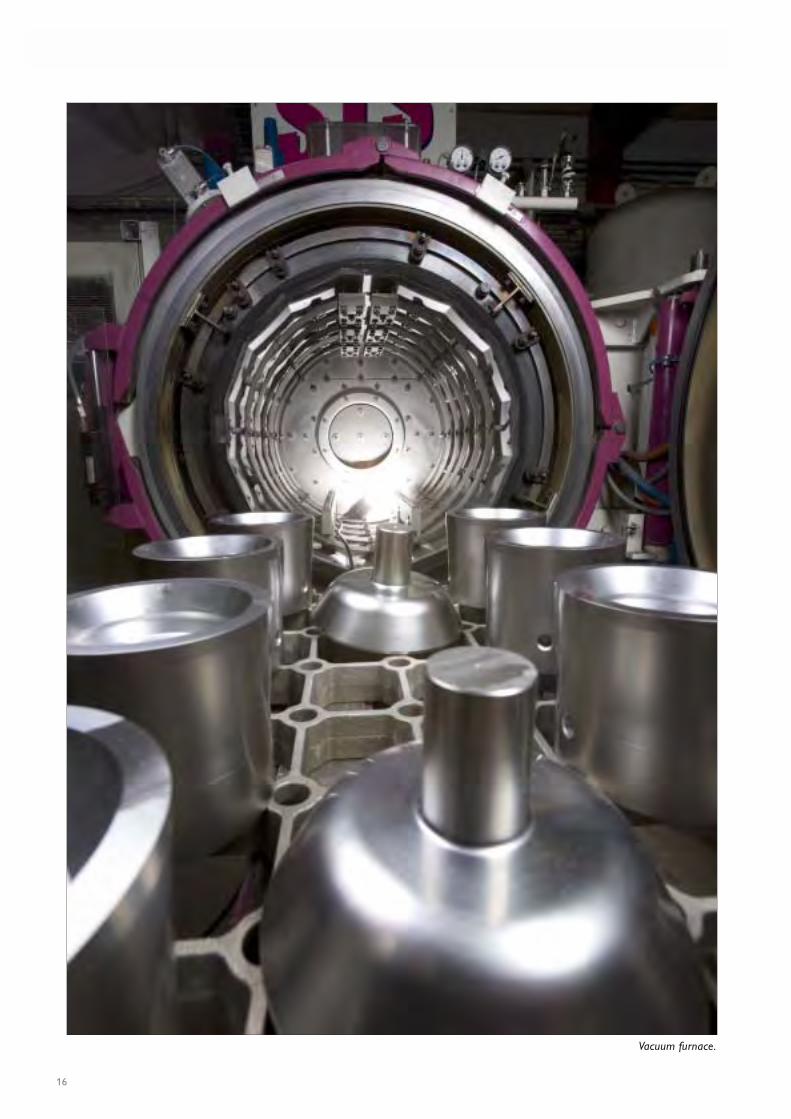
Vacuum furnace.
HEAT TREATMENT OF TOOL STEEL
17
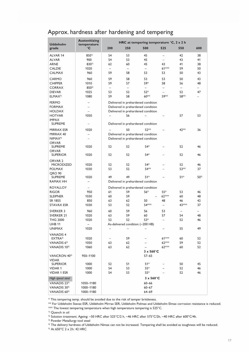
AustenitizingUddeholm temperaturegrade °C 200 250 500 525 550 600
ALVAR 14 8501) 54 53 45 – 42 38ALVAR 900 54 53 45 – 43 41ARNE 8301) 62 60 45 43 41 38CALDIE 1020 – – – 61*** 59 50CALMAX 960 59 58 53 53 50 43
CARMO 960 59 58 53 53 50 43CHIPPER 1010 59 57 59* 58 56 48CORRAX 8502) – – – – – –DIEVAR 1025 53 52 52* – 52 47ELMAX3) 1080 59 58 60** 59** 58** –
FERMO – Delivered in prehardened conditionFORMAX – Delivered in prehardened conditionHOLDAX – Delivered in prehardened conditionHOTVAR 1050 – 56 – – 57 53IMPAX SUPREME – Delivered in prehardened condition
MIRRAX ESR 1020 – 50 52** – 42** 36MIRRAX 40 – Delivered in prehardened conditionNIMAX4) – Delivered in prehardened conditionORVAR SUPREME 1020 52 52 54* – 52 46ORVAR SUPERIOR 1020 52 52 54* – 52 46
ORVAR 2 MICRODIZED 1020 52 52 54* – 52 46POLMAX 1030 53 52 54** – 53** 37QRO 90 SUPREME 1020 49 49 51* – 51* 505)
RAMAX HH – Delivered in prehardened condition
ROYALLOY – Delivered in prehardened conditionRIGOR 950 61 59 56* 55* 53 46SLEIPNER 1030 60 59 – 62*** 60 48SR 1855 850 63 62 50 48 46 42STAVAX ESR 1030 53 52 54*** – 43*** 37
SVERKER 3 960 60 59 56 53 – –SVERKER 21 1020 63 59 60 57 54 48THG 2000 1020 52 52 53* – 52 46UHB 11 – As-delivered condition (~200 HB)UNIMAX 1020 – – – – 55 49
VANADIS 4 EXTRA3) 1020 – 59 – 61*** 60 52VANADIS 63) 1050 63 62 – 62*** 59 52VANADIS 103) 1060 63 62 – 62*** 60 52
3 x 560°CVANCRON 403) 950–1100 57–65VIDAR SUPERIOR 1000 52 51 51* – 50 45VIDAR 1 1000 54 53 55* – 52 46VIDAR 1 ESR 1000 54 53 55* – 52 46
High speed steel 3 x 560°C
VANADIS 233) 1050–1180 60–66VANADIS 303) 1000–1180 60–67VANADIS 603) 1000–1180 64–69
* This tempering temp. should be avoided due to the risk of temper brittleness.** For Uddeholm Stavax ESR, Uddeholm Mirrax SER, Uddeholm Polmax and Uddeholm Elmax corrosion resistance is reduced.*** The lowest tempering temperature when high temperature tempering is 525°C.1) Quench in oil2) Solution treatment. Ageing: ~50 HRC after 525°C/2 h, ~46 HRC after 575°C/2h, ~40 HRC after 600°C/4h.3) Powder Metallurgy tool steel4) The delivery hardness of Uddeholm Nimax can not be increased. Tempering shall be avoided as toughness will be reduced.5) At 650°C 2 x 2h: 42 HRC
Approx. hardness after hardening and tempering
HRC at tempering temperature °C, 2 x 2 h
HEAT TREATMENT OF TOOL STEEL
18
78 133 140 446 4685 152 160 510 5291 171 180 570 5895 190 200 637 6598 209 220 696 71
228 240 756 77247 260 824 84265 280 883 90
30 284 300 951 9733 303 320 1020 104
35 322 340 1080 11037 341 360 1150 11739 360 380 1210 12341 379 400 1280 13042 397 420 1340 137
44 415 440 1410 14446 433 460 1470 15047 452 480 1530 15648 471 500 1610 16450 488 520 1690 172
51 507 540 1770 18052 525 560 1850 18853 545 580 1940 19854 564 60055 584 620
56 601 64057 620 66059 638 68059 70060 720
61 74062 76063 78064 80064 820
65 84066 86066 880
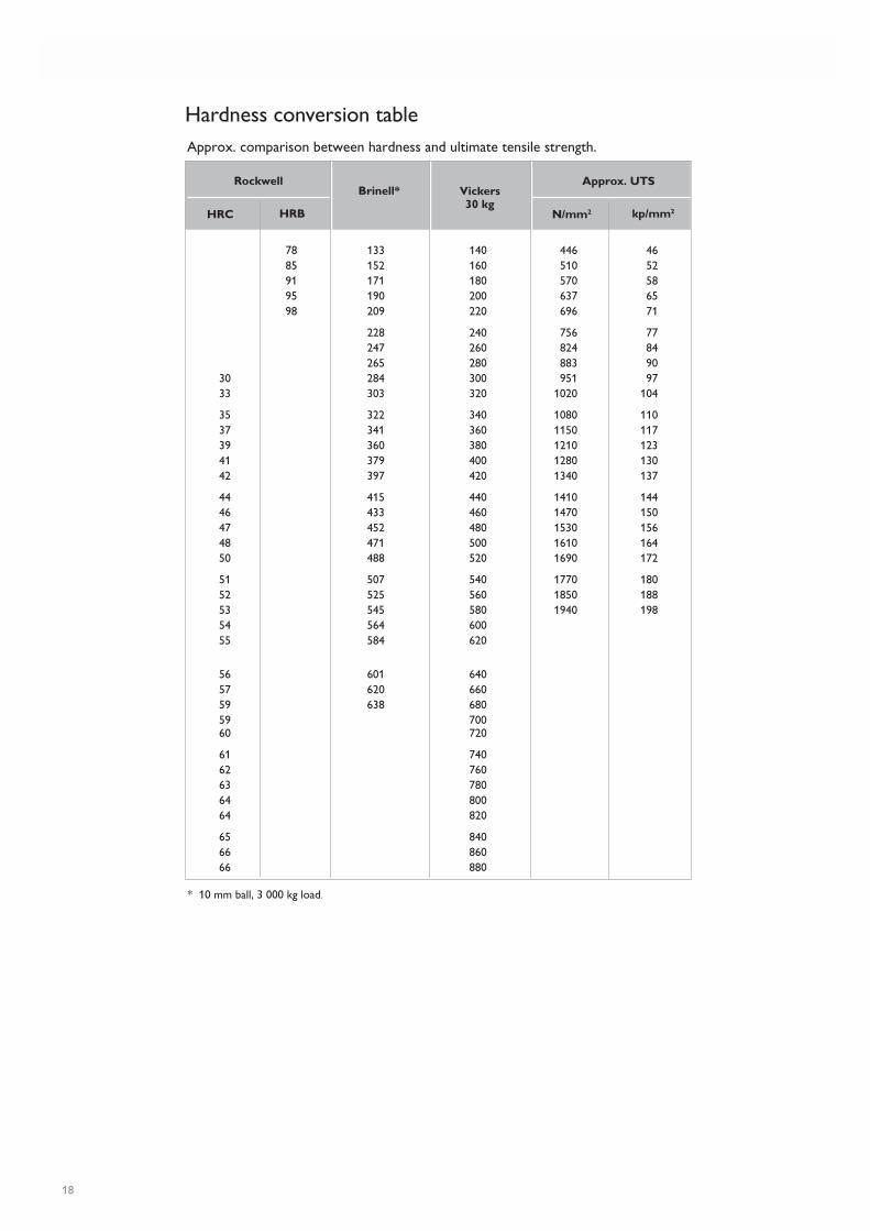
* 10 mm ball, 3 000 kg load.
Hardness conversion tableApprox. comparison between hardness and ultimate tensile strength.
Rockwell Approx. UTSBrinell* Vickers
30 kgN/mm2 kp/mm2HRBHRC

www.assab.com www.uddeholm.com
Network of excellenceUddeholm is present on every continent. This ensures you
high-quality Swedish tool steel and local support wherever you
are. Assab is our wholly-owned subsidiary and exclusive sales
channel, representing Uddeholm in the Asia Pacific area.
Together we secure our position as the world’s leading supplier
of tooling materials.

UD
DEH
OLM
120312.1000 / TRYC
KERI KNA
PPEN, KA
RLSTAD
201203199
Uddeholm is the world’s leading supplier of tooling materials. This
is a position we have reached by improving our customers’ everyday
business. Long tradition combined with research and product develop-
ment equips Uddeholm to solve any tooling problem that may arise.
It is a challenging process, but the goal is clear – to be your number one
partner and tool steel provider.
Our presence on every continent guarantees you the same high quality
wherever you are. Assab is our wholly-owned subsidiary and exclusive
sales channel, representing Uddeholm in the Asia Pacific area.
Together we secure our position as the world’s leading supplier of
tooling materials. We act worldwide, so there is always an Uddeholm
or Assab representative close at hand to give local advice and support.
For us it is all a matter of trust – in long-term partnerships as well as in
developing new products. Trust is something you earn, every day.
For more information, please visit www.uddeholm.com or www.assab.com