Embed Size (px)
Citation preview

UDDEHOLM UNIMAX®

SS-EN ISO 9001SS-EN ISO 14001
This information is based on our present state of knowledge and is intended to provide generalnotes on our products and their uses. It should not therefore be construed as a warranty ofspecific properties of the products described or a warranty for fitness for a particular purpose.
Classified according to EU Directive 1999/45/ECFor further information see our “Material Safety Data Sheets”.
Edition 6, 09.2015The latest revised edition of this brochure is the English version,which is always published on our web site www.uddeholm.com
© UDDEHOLMS ABNo part of this publication may be reproduced or transmitted for commercial purposes
without permission of the copyright holder.
UDDEHOLM UNIMAX
3
UDDEHOLM UNIMAX®
The excellent properties offered enable Uddeholm Unimax to be used for many
tooling applications. Reduced cycle time and longer tool life contributes to
improve the overall economy. With an exceptional combination of high ductility
and high hardness, Uddeholm Unimax is perfect when moulding plastic details and
constructions that mean hard wear on the mould.
For the customers Uddeholm Unimax gives a lot of benefits:
• excellent for reinforced plastic details, suitable for long run production and
compression moulding. The combination of high ductility and high hardness
means improved durability and wear resistance
• longer tool life
• good surface treatment properties.
• very good hardenability which results in the same good properties throughout
the entire cross-section
The excellent combination of toughness and hardness also makes it a universal
engineering grade.
As we say; The harder, the better!
UDDEHOLM UNIMAX
4
GeneralUddeholm Unimax is a chromium-molybde-num-vanadium alloyed tool steel which ischaracterized by:
• Excellent toughness and ductility in alldirections
• Good wear resistance
• Good dimensional stability at heat treatmentand in service
• Excellent through-hardening properties
• Good resistance to tempering back
• Good hot strength
• Good thermal fatigue resistance
• Excellent polishability
Typical C Si Mn Cr Mo Vanalysis % 0,5 0,2 0,5 5,0 2,3 0,5
Standardspecification None
Deliverycondition Soft annealed to approx. 185 HB
Colour code Brown/grey
ApplicationsUddeholm Unimax is suitable for long runproduction moulds, moulds for reinforcedplastics and compression moulding.
Uddeholm Unimax is a problem solver insevere cold work tooling applications such asheavy duty blanking, cold forging and threadrolling, where high chipping resistance isrequired.
Engineering and hot work applicationsrequiring high hardness and toughness are alsoan option.
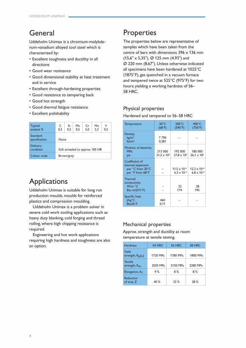
PropertiesThe properties below are representative ofsamples which have been taken from thecentre of bars with dimensions 396 x 136 mm(15,6" x 5,35"), Ø 125 mm (4,93") andØ 220 mm (8,67"). Unless otherwise indicatedall specimens have been hardened at 1025°C(1875°F), gas quenched in a vacuum furnaceand tempered twice at 525°C (975°F) for twohours; yielding a working hardness of 56–58 HRC.
Physical propertiesHardened and tempered to 56–58 HRC
Temperature 20°C 200°C 400°C(68°F) (390°F) (750°F)
Density,kg/m3 7 790 – –lbs/in3 0,281
Modulus of elasticityMPa 213 000 192 000 180 000psi 31,2 x 10⁶ 27,8 x 10⁶ 26,1 x 10⁶
Coefficient ofthermal expansion
per °C from 20°C – 11,5 x 10⁻⁶ 12,3 x 10⁻⁶
per °F from 68°F – 6,3 x 10⁻⁶ 6,8 x 10⁻⁶
Thermalconductivity
W/m °C – 25 28Btu in/(ft2h°F) – 174 195
Specific heatJ/kg°C 460 – –Btu/lb°F 0,11
Mechanical propertiesApprox. strength and ductility at roomtemperature at tensile testing.
Hardness 54 HRC 56 HRC 58 HRC
Yieldstrength, Rp0,2 1720 MPa 1780 MPa 1800 MPa
Tensilestrength, Rm 2050 MPa 2150 MPa 2280 MPa
Elongation, A5 9 % 8 % 8 %
Reductionof area, Z 40 % 32 % 28 %
UDDEHOLM UNIMAX
5
100 200 300 400 500 600°C
210 390 570 750 930 1110°F
Testing temperature
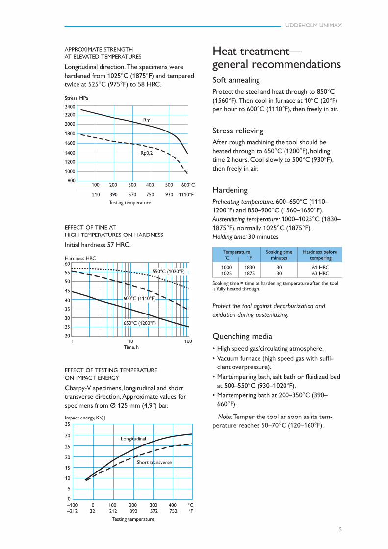
APPROXIMATE STRENGTHAT ELEVATED TEMPERATURES
Longitudinal direction. The specimens werehardened from 1025°C (1875°F) and temperedtwice at 525°C (975°F) to 58 HRC.
Heat treatment—general recommendationsSoft annealingProtect the steel and heat through to 850°C(1560°F). Then cool in furnace at 10°C (20°F)per hour to 600°C (1110°F), then freely in air.
Stress relievingAfter rough machining the tool should beheated through to 650°C (1200°F), holdingtime 2 hours. Cool slowly to 500°C (930°F),then freely in air.
HardeningPreheating temperature: 600–650°C (1110–1200°F) and 850–900°C (1560–1650°F).Austenitizing temperature: 1000–1025°C (1830–1875°F), normally 1025°C (1875°F).Holding time: 30 minutes
Temperature Soaking time Hardness before°C °F minutes tempering
1000 1830 30 61 HRC1025 1875 30 63 HRC
Soaking time = time at hardening temperature after the toolis fully heated through.
Protect the tool against decarburization andoxidation during austenitizing.
Quenching media
• High speed gas/circulating atmosphere.
• Vacuum furnace (high speed gas with suffi-cient overpressure).
• Martempering bath, salt bath or fluidized bedat 500–550°C (930–1020°F).
• Martempering bath at 200–350°C (390–660°F).
Note: Temper the tool as soon as its tem-perature reaches 50–70°C (120–160°F).
EFFECT OF TIME ATHIGH TEMPERATURES ON HARDNESS
Initial hardness 57 HRC.
1 10 100 Time, h
550°C (1020°F)
Hardness HRC60
55
50
45
40
35
30
25
20
Rm
600°C (1110°F)
650°C (1200°F)
EFFECT OF TESTING TEMPERATUREON IMPACT ENERGY
Charpy-V specimens, longitudinal and shorttransverse direction. Approximate values forspecimens from Ø 125 mm (4,9") bar.
Impact energy, KV, J35
30
25
20
15
10
5
0
Longitudinal
Short transverse
–100 0 100 200 300 400 °C–212 32 212 392 572 752 °F
Testing temperature
Stress, MPa
2400
2200
2000
1800
1600
1400
1200
1000
800
Rp0,2
UDDEHOLM UNIMAX
6
2000
1800
1600
1400
1200
1000
800
600
400
200
°C°F
Air cooling ofbars, Ø mm
1 10 100 1 000 10 000 100 000 Seconds
1 10 100 1 000 Minutes
1 10 100 Hour
0.2 1.5 10 90 600
1100
1000
900
800
700
600
500
400
300
200
100
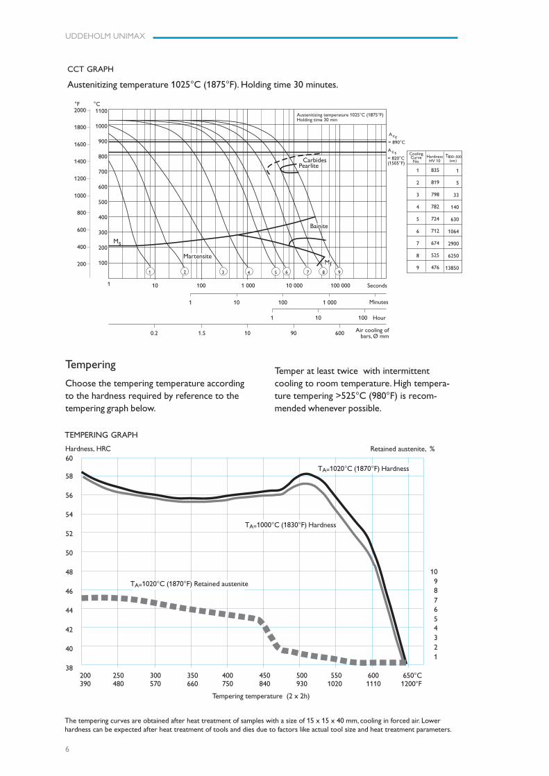
CoolingCurveNo.
HardnessHV 10
800–500 (sec)
T
= 890°C
= 820°C(1505°F)
Acf
Acs
1 2 3 4 5 6 7 8
Ms
Martensite
9
Mf
PearliteCarbides
Bainite
1
2
3
4
5
6
7
8
9
835
819
798
782
724
712
674
525
476
1
5
33
140
630
1064
2900
6250
13850
Austenitizing temperature 1025°C (1875°F)Holding time 30 min
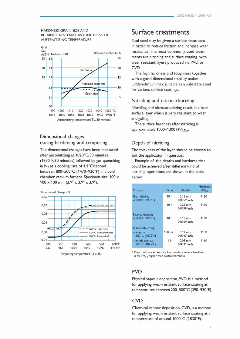
Tempering
Choose the tempering temperature accordingto the hardness required by reference to thetempering graph below.
TEMPERING GRAPH
Retained austenite, %Hardness, HRC60
58
56
54
52
50
48
46
44
42
40
38
TA=1020°C (1870°F) Hardness
200 250 300 350 400 450 500 550 600 650°C 390 480 570 660 750 840 930 1020 1110 1200°F
Tempering temperature (2 x 2h)
TA=1000°C (1830°F) Hardness
TA=1020°C (1870°F) Retained austenite
The tempering curves are obtained after heat treatment of samples with a size of 15 x 15 x 40 mm, cooling in forced air. Lowerhardness can be expected after heat treatment of tools and dies due to factors like actual tool size and heat treatment parameters.
Temper at least twice with intermittentcooling to room temperature. High tempera-ture tempering >525°C (980°F) is recom-mended whenever possible.
10 9 8 7 6 5 4 3 2 1
CCT GRAPH
Austenitizing temperature 1025°C (1875°F). Holding time 30 minutes.
UDDEHOLM UNIMAX
7
Surface treatmentsTool steel may be given a surface treatmentin order to reduce friction and increase wearresistance. The most commonly used treat-ments are nitriding and surface coating withwear resistant layers produced via PVD orCVD.
The high hardness and toughness togetherwith a good dimensional stability makesUddeholm Unimax suitable as a substrate steelfor various surface coatings.
Nitriding and nitrocarburizingNitriding and nitrocarburizing result in a hardsurface layer which is very resistant to wearand galling.
The surface hardness after nitriding isapproximately 1000–1200 HV0,2kg.
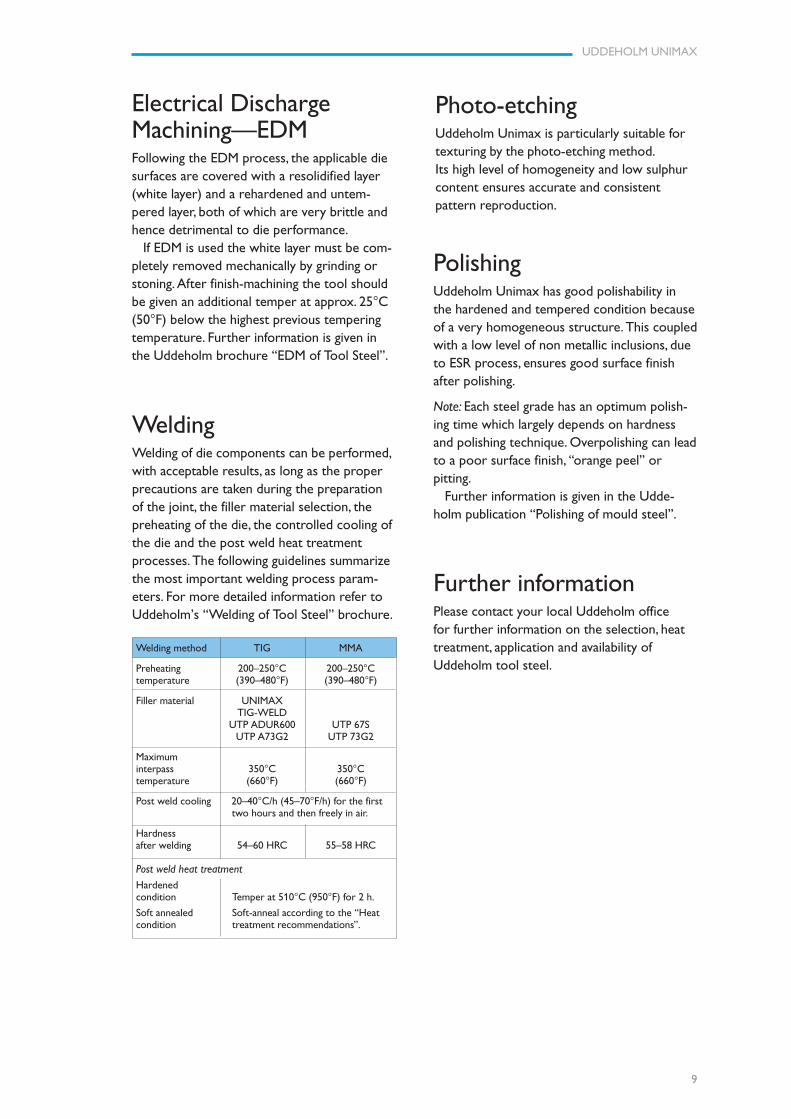
Dimensional changesduring hardening and temperingThe dimensional changes have been measuredafter austenitizing at 1020°C/30 minutes(1870°F/30 minutes) followed by gas quenchingin N2 at a cooling rate of 1,1°C/secondbetween 800–500°C (1470–930°F) in a coldchamber vacuum furnace. Specimen size: 100 x100 x 100 mm (3,9" x 3,9" x 3,9").
Dimensional changes, %
0,16
0,12
0,08
0,04
0,00
–0,04500 520 540 560 580 600°C932 968 1004 1040 1076 1112°F
Tempering temperature (2 x 2h)
1020°C Transverse
1020°C Short transverse
1020°C Longitudinal
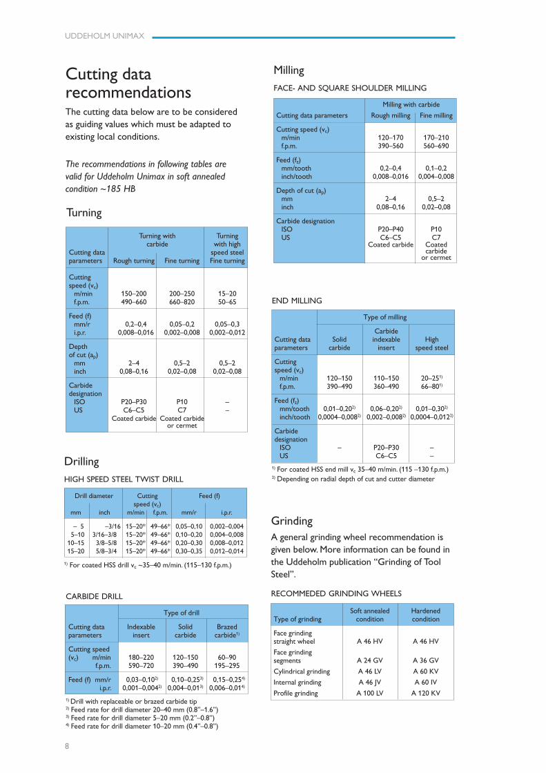
HARDNESS, GRAIN SIZE ANDRETAINED AUSTENITE AS FUNCTIONS OFAUSTENITIZING TEMPERATURE
25
20
15
65
64
63
62
61
60
Hardness, HRC
GrainsizeASTM
Hardness
Grain size
Retained austenite
990 1000 1010 1020 1030 1040 1050 °C1815 1830 1850 1870 1885 1905 1920 °F
Austenitizing temperature TA, 30 minutes
Retained austenite %
25
20
15
10
5
PVDPhysical vapour deposition, PVD, is a methodfor applying wear-resistant surface coating attemperatures between 200–500°C (390–930°F).
CVDChemical vapour deposition, CVD, is a methodfor applying wear-resistant surface coating at atemperature of around 1000°C (1830°F).
Depth of nitridingThe thickness of the layer should be chosen tosuit the application in question.
Example of the depths and hardness thatcould be achieved after different kind ofnitriding operations are shown in the tablebelow.
* Depth of case = distance from surface where hardnessis 50 HV0.2 higher than matrix hardness
HardnessProcess Time Depth* HV0,2
Gas nitriding 10 h 0.15 mm 1180at 510°C (950°F) 0.0059 inch
30 h 0.25 mm 11800.0098 inch
Plasma nitridingat 480°C (895°F) 10 h 0.15 mm 1180
0.0059 inch
Nitrocarburizing– in gas at 150 min. 0.12 mm 1130 580°C (1075°F) 0.0047 inch
– in salt bath at 1 h 0.08 mm 1160 580°C (1075°F) 0.0031 inch
UDDEHOLM UNIMAX
8
END MILLING
Type of milling
CarbideCutting data Solid indexable Highparameters carbide insert speed steel
Cuttingspeed (vc)
m/min 120–150 110–150 20–251)
f.p.m. 390–490 360–490 66–801)
Feed (fz)mm/tooth 0,01–0,202) 0,06–0,202) 0,01–0,302)
inch/tooth 0,0004–0,0082) 0,002–0,0082) 0,0004–0,0122)
Carbidedesignation
ISO – P20–P30 –US C6–C5 –
1) For coated HSS end mill vc 35–40 m/min. (115 –130 f.p.m.)2) Depending on radial depth of cut and cutter diameter
GrindingA general grinding wheel recommendation isgiven below. More information can be found inthe Uddeholm publication “Grinding of ToolSteel”.
RECOMMEDED GRINDING WHEELS
Soft annealed HardenedType of grinding condition condition
Face grindingstraight wheel A 46 HV A 46 HV
Face grindingsegments A 24 GV A 36 GV
Cylindrical grinding A 46 LV A 60 KV
Internal grinding A 46 JV A 60 IV
Profile grinding A 100 LV A 120 KV
Drilling
HIGH SPEED STEEL TWIST DRILL
Drill diameter Cutting Feed (f)speed (vc)
mm inch m/min f.p.m. mm/r i.p.r.
– 5 –3/16 15–20* 49–66* 0,05–0,10 0,002–0,004 5–10 3/16–3/8 15–20* 49–66* 0,10–0,20 0,004–0,00810–15 3/8–5/8 15–20* 49–66* 0,20–0,30 0,008–0,01215–20 5/8–3/4 15–20* 49–66* 0,30–0,35 0,012–0,014
1) For coated HSS drill vc ~35–40 m/min. (115–130 f.p.m.)
CARBIDE DRILL
Type of drill
Cutting data Indexable Solid Brazedparameters insert carbide carbide1)
Cutting speed(vc) m/min 180–220 120–150 60–90
f.p.m. 590–720 390–490 195–295
Feed (f) mm/r 0,03–0,102) 0,10–0,253) 0,15–0,254)
i.p.r. 0,001–0,0042) 0,004–0,013) 0,006–0,014)
1) Drill with replaceable or brazed carbide tip2) Feed rate for drill diameter 20–40 mm (0.8”–1.6”)3) Feed rate for drill diameter 5–20 mm (0.2”–0.8”)4) Feed rate for drill diameter 10–20 mm (0.4”–0.8”)
Milling
FACE- AND SQUARE SHOULDER MILLING
Milling with carbide
Cutting data parameters Rough milling Fine milling
Cutting speed (vc)m/min 120–170 170–210f.p.m. 390–560 560–690
Feed (fz)mm/tooth 0,2–0,4 0,1–0,2inch/tooth 0,008–0,016 0,004–0,008
Depth of cut (ap)mm 2–4 0,5–2inch 0,08–0,16 0,02–0,08
Carbide designationISO P20–P40 P10US C6–C5 C7
Coated carbide Coatedcarbide
or cermet
Turning
Turning with Turningcarbide with high
Cutting data speed steelparameters Rough turning Fine turning Fine turning
Cuttingspeed (vc)
m/min 150–200 200–250 15–20f.p.m. 490–660 660–820 50–65
Feed (f)mm/r 0,2–0,4 0,05–0,2 0,05–0,3i.p.r. 0,008–0,016 0,002–0,008 0,002–0,012
Depthof cut (ap)
mm 2–4 0,5–2 0,5–2inch 0,08–0,16 0,02–0,08 0,02–0,08
Carbidedesignation
ISO P20–P30 P10 –US C6–C5 C7 –
Coated carbide Coated carbideor cermet
Cutting datarecommendationsThe cutting data below are to be consideredas guiding values which must be adapted toexisting local conditions.
The recommendations in following tables arevalid for Uddeholm Unimax in soft annealedcondition ~185 HB
UDDEHOLM UNIMAX
9
Further informationPlease contact your local Uddeholm officefor further information on the selection, heattreatment, application and availability ofUddeholm tool steel.
Photo-etchingUddeholm Unimax is particularly suitable fortexturing by the photo-etching method.Its high level of homogeneity and low sulphurcontent ensures accurate and consistentpattern reproduction.
WeldingWelding of die components can be performed,with acceptable results, as long as the properprecautions are taken during the preparationof the joint, the filler material selection, thepreheating of the die, the controlled cooling ofthe die and the post weld heat treatmentprocesses. The following guidelines summarizethe most important welding process param-eters. For more detailed information refer toUddeholm’s “Welding of Tool Steel” brochure.
Electrical DischargeMachining—EDMFollowing the EDM process, the applicable diesurfaces are covered with a resolidified layer(white layer) and a rehardened and untem-pered layer, both of which are very brittle andhence detrimental to die performance.
If EDM is used the white layer must be com-pletely removed mechanically by grinding orstoning. After finish-machining the tool shouldbe given an additional temper at approx. 25°C(50°F) below the highest previous temperingtemperature. Further information is given inthe Uddeholm brochure “EDM of Tool Steel”.
Welding method TIG MMA
Preheating 200–250°C 200–250°Ctemperature (390–480°F) (390–480°F)
Filler material UNIMAXTIG-WELD
UTP ADUR600 UTP 67SUTP A73G2 UTP 73G2
Maximuminterpass 350°C 350°Ctemperature (660°F) (660°F)
Post weld cooling 20–40°C/h (45–70°F/h) for the first two hours and then freely in air.
Hardnessafter welding 54–60 HRC 55–58 HRC
Post weld heat treatment
Hardenedcondition Temper at 510°C (950°F) for 2 h.
Soft annealed Soft-anneal according to the “Heatcondition treatment recommendations”.
PolishingUddeholm Unimax has good polishability inthe hardened and tempered condition becauseof a very homogeneous structure. This coupledwith a low level of non metallic inclusions, dueto ESR process, ensures good surface finishafter polishing.
Note: Each steel grade has an optimum polish-ing time which largely depends on hardnessand polishing technique. Overpolishing can leadto a poor surface finish, “orange peel” orpitting.
Further information is given in the Udde-holm publication “Polishing of mould steel”.

UDDEHOLM UNIMAX
10
www.assab.com www.uddeholm.com
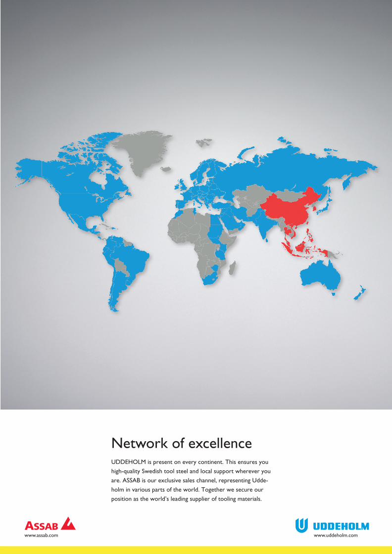
Network of excellenceUDDEHOLM is present on every continent. This ensures you
high-quality Swedish tool steel and local support wherever you
are. ASSAB is our exclusive sales channel, representing Udde-
holm in various parts of the world. Together we secure our
position as the world’s leading supplier of tooling materials.
UDDEHOLM is the world’s leading supplier of tooling materials. This
is a position we have reached by improving our customers’ everyday
business. Long tradition combined with research and product develop-
ment equips Uddeholm to solve any tooling problem that may arise.
It is a challenging process, but the goal is clear – to be your number one
partner and tool steel provider.
Our presence on every continent guarantees you the same high quality
wherever you are. ASSAB is our exclusive sales channel, representing
Uddeholm in various parts of the world. Together we secure our
position as the world’s leading supplier of tooling materials. We act
worldwide, so there is always an Uddeholm or ASSAB representative
close at hand to give local advice and support. For us it is all a matter of
trust – in long-term partnerships as well as in developing new products.
Trust is something you earn, every day.
For more information, please visit www.uddeholm.com, www.assab.com
or your local website.
UD
DEH
OLM
150204 / 1509.75 / STROKIRK KN
APPEN
09.2015