Embed Size (px)
Citation preview

1
UCSB Solar Photovoltaic PPA Project Phase III UNIVERSITY OF CALIFORNIA, SANTA BARBARA
Notice of Impending Development
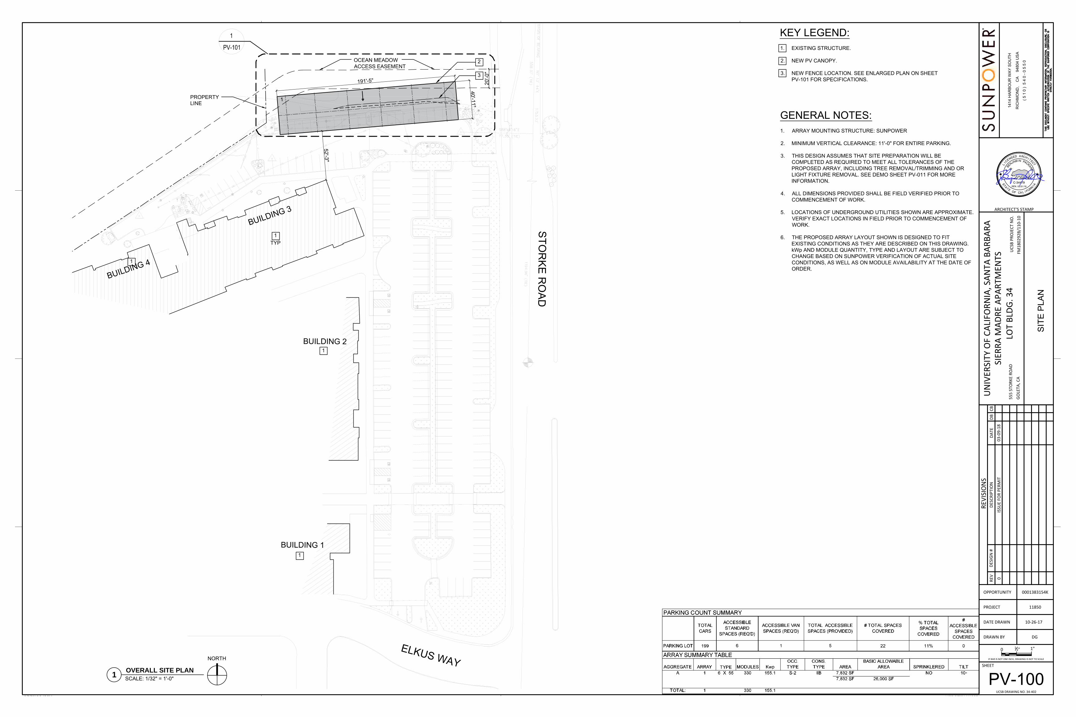
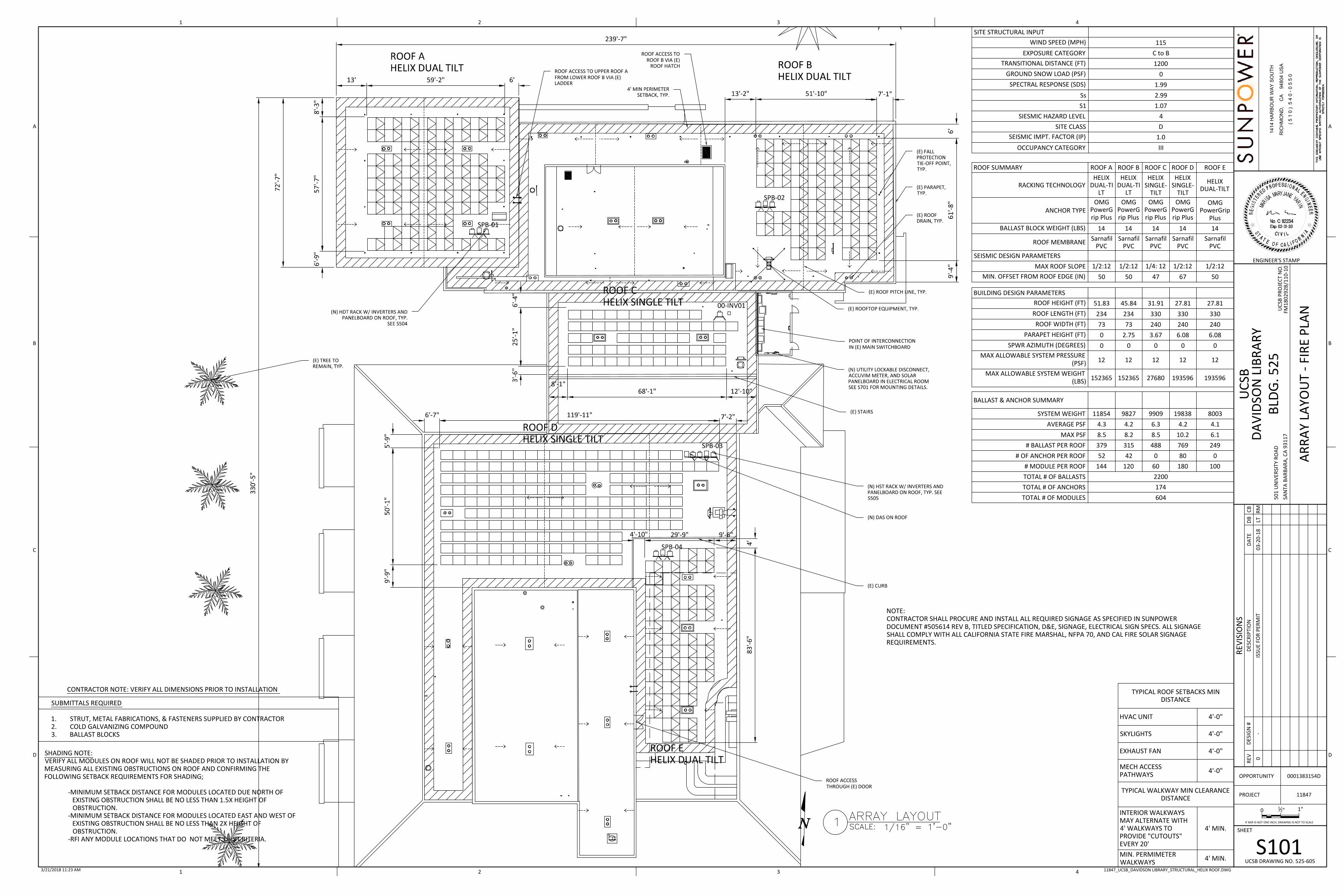
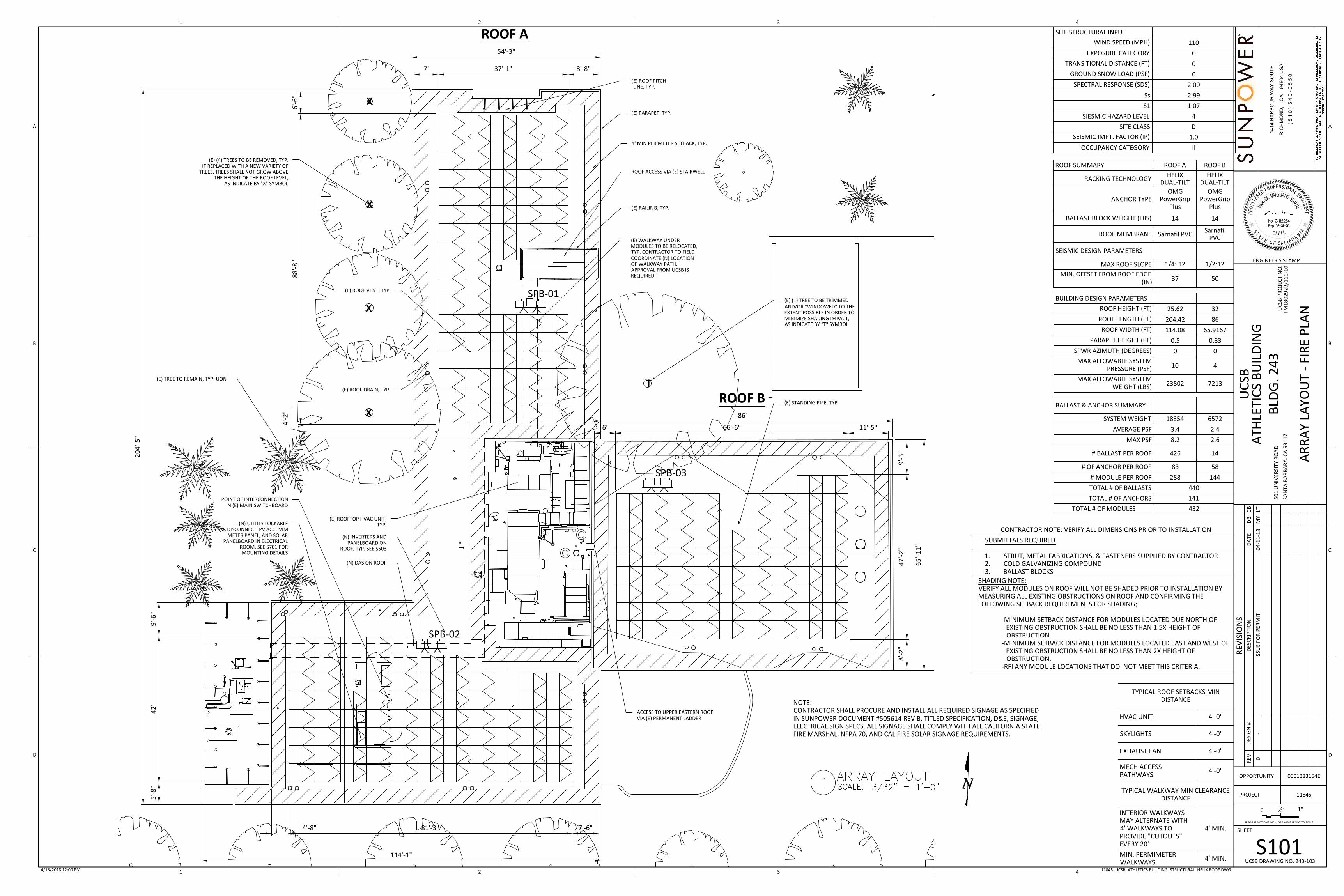
This Notice of Impending Development is for the installation of 6 roof-top and one canopy style solar systems on the University of California Santa Barbara’s Main and North Campus’. PROJECT DESCRIPTION Project Location: Solar Photovoltaic Systems will be installed on the roof tops of seven building structures on the Main Campus and on a carport-style canopy above a surface parking lot at the Sierra Madre Villages student housing site (see a map of locations attached). Purpose and Need: The Solar Photovoltaic project will install systems in eight locations across Main and North Campuses at the University of California, Santa Barbara. The systems would be connected to the Campus’ 12KV electrical distribution system. This project would expand an existing 20 year contract (known as a Power Purchase Agreement or PPA) between the University and a solar electricity provider for third party installation, operation and maintenance of solar photovoltaic (PV) systems on campus facilities in order to reduce and offset current and long-term electrical utility costs as well to reduce greenhouse gas emissions associated with the campus' electrical demand. The systems would either be removed, purchased by the University, or the contract would be extended after the initial 20 year term. Setting and Program: The preliminary project design proposes to install approximately 3,318 modules that cover approximately 58,464 square feet of area in various locations (see preliminary project plans in Attachment B). Six solar PV systems would be installed at the following buildings: (1) Building 534 (Arts Building), (2) Building 243 (Intercollegiate Athletics Building), (3) Building 223 (Theater and Dance West Building), (4) Building 525 (Davidson Library), (5) Building 591 (Kerr Hall), and (6) Building 552 (Cheadle Hall). The surface carport will be constructed at UCSB's Sierra Madre Villages student housing site. The systems are expected to offset the University's peak-time electricity costs by providing at least 2,140,000 kilowatt-hours of electricity each year in the initial years with a degradation factor applied to subsequent years. All systems would be designed to withstand local maximum wind speeds and seismic loading. The project operations and maintenance would include approximately two module washings per year; either with pressurized water methods or robotic methods. The project proposes to remove five trees. In accordance with LRDP Policy ESH-28 and Appendix 2, Campus Tree Trimming and Removal Program the trees will be replaced at a 1:1 ratio. The project would remove four planted sycamore trees adjacent to the Intercollegiate Athletics Building and one pine tree adjacent to the Arts Building. The sycamore trees are approximately 50-feet tall, 18-inch diameter, and although are a tree typically native to California, these trees were planted when ICA was constructed in 2002-03 (NOID 3-02). The sycamore trees were planted in 2004 and are approximately 14 years old. Replacement trees considered include Arbutus ‘Marina’ or Magnolia ‘Little Gem.’

2
The pine tree near the Arts building is approximately 60 feet tall, 22-inch diameter, and is approximately 50 years old. The pine tree shows sap production at beetle attack sites at the base of the tree. Other trees in this location are dead from the same. Coast live oak is considered for a replacement tree in this location. A tree replacement plan is attached. All of the conduits and other equipment will be mounted at or below the roof level of the roof top arrays and will not be visible from the exterior. The carport installation would include a cable management system and 360 degree fascia to minimize aesthetic impact. Mounting materials and canopy structures would be low glare (painted beams and galvanized steel). The modules would include anti-reflective glass (Shields 2010). The Sierra Madre Apartments parking lot solar array would be installed on the northeast corner of the parking lot. A degraded constructed parking lot swale (see attached photos) is within the shaded area of the canopy and an emergency access (access easement) dirt road is further north outside the canopy. Even further north is the northern Sierra Madre restoration area. Currently there is a six-foot chain link fence on the north perimeter of the parking lot swale which delineates the North Campus Open Space Restoration project area. This fence will be relocated during installation of the array and eventually removed altogether once the NCOS project is complete. The Solar array would be installed on ten degree fixed-tilt carport canopies supported on piers with a minimum vertical clearance of 11 feet for standard vehicles. The system would overhang approximately 7,832 square feet, or 0.2 acres. The six pedestals supporting the structure would be installed within the parking lot swale on the north edge of the parking lot. The maximum height of the canopies would be approximately 20 feet above the parking surface. Canopies would not conflict with the required 20 feet of minimum clearance for emergency vehicle access routes. One light pole within the proposed array boundaries would be removed and replaced with new dark-sky compliant fully-shielded lighting (3,000 Kelvin in accordance with LRDP Outdoor Lighting Plan standards) which would be attached to the underside of the canopies and shielded to eliminate any potential glare into the restored area and housing further north of the parking lot. In addition, one nearby light pole would be removed, as it would shade the array. The system would include 330 modules connected to 6 inverters. The system would be tied in to the existing campus electrical infrastructure at Sierra Madre building 1123 within the main electrical room. No parking spaces would be removed for the project. Schedule: Project construction would begin approximately July 2018 and finish around November 2018. It is anticipated that roof system procurement and construction would begin first followed by the surface parking canopy system procurement and construction. The entire project will take five to six months to complete. Background and Project Objectives: The project is consistent with the Environmental Impact Report (EIR) prepared for the 2010 UCSB Long Range Development Plan (LRDP) (UCSB 2008). The LRDP EIR concluded that there would be a less than significant impact on energy resources from implementation of the 2010 LRDP (build out) and no mitigation is required. The University takes an aggressive approach to the efficient use of resources and the Campus Energy Program is aimed at fostering the efficient use of energy resources. One component of the

3
Campus Energy Program is to encourage all facilities to aggressively apply energy conservation measures including installation of solar panels. The proposed project will provide an alternative source of energy to the Santa Barbara Campus. The project would meet over 12 percent of the Campus’s electrical needs. The project will include an online energy information system that will allow campus personnel to monitor production at each solar array, as well as campus-level energy monitoring. The project is consistent with LRDP Policy SCEN-04 since rooftop solar energy systems are not included in the building height measurements. Policy SCEN-04: - Development shall not exceed the height limits established in Figure D.4. Height shall be measured as the vertical distance at any one point from the existing grade to the highest point of the top of the roof of the structure. The highest point shall be the coping of a flat roof, or peak of the ridge for a pitch or hip roof. Mechanical and electrical equipment and solar energy systems on the roof shall not be included in the height measurement. However, mechanical equipment shall be setback as far as feasible from public roads and other viewing areas and screened by architectural features. The proposed project implements LRDP Policy SUST-06 with installation of solar power on campus. Policy SUST-06: The University shall minimize energy use and reduce pollution through such methods as the use of solar power and other renewable energy systems, natural lighting, passive solar heating and cooling and other techniques to produce energy efficient development, building management techniques such as smart metering and lighting/appliance management systems that limit waste, and use of light colored buildings and roofing materials. The proposed project is consistent with LRDP Policy ESH-28 and Appendix 2, Campus Tree Trimming and Removal Program. A tree replacement plan is included with this submittal and the trees proposed to be removed will be replaced at a minimum of 1:1. Bird nesting surveys would be conducted prior to tree removal. Policy ESH-28: A. The routine trimming and/or removal of trees on campus necessary to maintain campus landscaping or to address potential public safety concerns shall be exempt from the requirement to obtain a Notice of Impending Development (NOID), unless otherwise required pursuant to subparagraph B, below, and provided that the trimming and/or removal activities are carried out consistent with all provisions and protocols of the certified Campus Tree Trimming and Removal Program in Appendix 2, except that the following shall require a NOID: 1. Trimming and/or removal of trees located within ESHA or on lands designated Open Space as covered in Policy ESH-29, 2. The removal of any tree associated with new development, re-development, or renovation shall be evaluated separately through the NOID process as detailed in subparagraph C, below; 3. The removal of tree windrows, and 4. Trimming and/or removal of egret, heron, or cormorant roosting trees proximate to the Lagoon.

4
B. All tree trimming and tree removal activities, including trimming or removal that is exempt from the requirement to obtain a Notice of Impending Development, shall be prohibited during the breeding and nesting season (February 15 to September 1) unless the University, in consultation with a qualified arborist, determines that: 1. Immediate tree trimming or tree removal action by the University is required to protect life and property of the University from imminent danger, authorization is required where such activity would occur in ESHA or Open Space through an emergency permit, 2. Trimming or removal of trees located outside of ESHA or Open Space areas during June 15 to September 1, provided where a qualified biologist has found that there are no active raptor nests or colonial birds roosts within 500 feet of the trees to be trimmed or removed, or 3. Is part of a development or redevelopment approved pursuant to a Notice of Impending Development. C. To preserve roosting habitat for bird species and monarch butterflies, tree(s) associated with new development, re-development, or renovation that are either native or have the potential to provide habitat for raptors or other sensitive species shall be preserved and protected to the greatest extent feasible. Where native, or otherwise biologically significant, trees are retained, new development shall be sited a minimum of five feet from the outer edge of that tree’s canopy drip-line. The removal of such trees shall be evaluated pursuant to the Notice of Impending Development for the new development. Prior to the removal of any native and/or sensitive tree for development purposes, the University shall conduct biological studies to show whether the tree(s) provide nesting, roosting, or foraging habitat for raptors and sensitive bird species, aggregation or significant foraging sites for monarch butterflies, or habitat for other sensitive biological resources. The Commission may condition the subject Notice of Impending Development to secure the seasonal timing restrictions and mitigation requirements otherwise set forth in the Campus Tree Trimming and Removal Program in Appendix 2. The proposed solar canopy is consistent with LRDP Policy ESH-44. The solar canopy will be installed within the Sierra Madre Apartments (Storke-Whittier property) parking lot outside of the 100-foot buffer from a restored wetland area to the north. The canopy would overhang approximately 7,832 square feet, or 0.2 acres of an adjacent emergency access road. The emergency access road is adjacent to the northern edge of the parking lot on the very southern edge of a wetland buffer and was approved in NOID-1-06 for the Sierra Madre Apartments. It is a dirt road with no vegetation and has recently been used to access portions of the North Campus Restoration Project. Pedestrian and bicycle access will be maintained on the access road and some vegetation may be planted there as landscaping however the road will not be restored as it is to be maintained as emergency access and a public access corridor. See attached Sierra Madre grading plans showing the emergency access road and wetland buffer. LRDP Policy ESH-44 – The wetland, riparian, and environmentally sensitive habitat areas on the North Parcel and the Storke-Whittier property shall be permanently retained and restored or enhanced pursuant to the approved restoration plan. The restoration and/or enhancement shall be implemented concurrently with the construction of the Sierra Madre and North Parcel Housing projects (NOID 1-06). Subsequent to successful completion of the restoration plan, these areas shall be maintained to ensure biological and hydrological functions and habitat value.
5
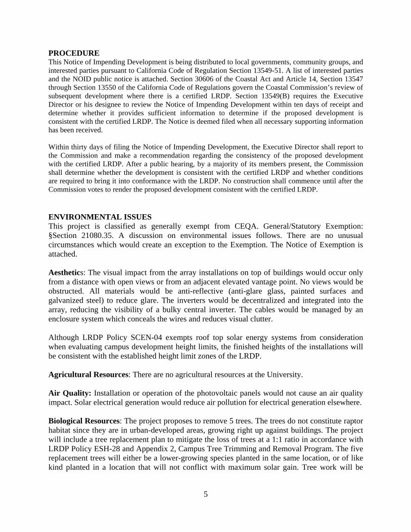
PROCEDURE This Notice of Impending Development is being distributed to local governments, community groups, and interested parties pursuant to California Code of Regulation Section 13549-51. A list of interested parties and the NOID public notice is attached. Section 30606 of the Coastal Act and Article 14, Section 13547 through Section 13550 of the California Code of Regulations govern the Coastal Commission’s review of subsequent development where there is a certified LRDP. Section 13549(B) requires the Executive Director or his designee to review the Notice of Impending Development within ten days of receipt and determine whether it provides sufficient information to determine if the proposed development is consistent with the certified LRDP. The Notice is deemed filed when all necessary supporting information has been received. Within thirty days of filing the Notice of Impending Development, the Executive Director shall report to the Commission and make a recommendation regarding the consistency of the proposed development with the certified LRDP. After a public hearing, by a majority of its members present, the Commission shall determine whether the development is consistent with the certified LRDP and whether conditions are required to bring it into conformance with the LRDP. No construction shall commence until after the Commission votes to render the proposed development consistent with the certified LRDP. ENVIRONMENTAL ISSUES This project is classified as generally exempt from CEQA. General/Statutory Exemption: §Section 21080.35. A discussion on environmental issues follows. There are no unusual circumstances which would create an exception to the Exemption. The Notice of Exemption is attached. Aesthetics: The visual impact from the array installations on top of buildings would occur only from a distance with open views or from an adjacent elevated vantage point. No views would be obstructed. All materials would be anti-reflective (anti-glare glass, painted surfaces and galvanized steel) to reduce glare. The inverters would be decentralized and integrated into the array, reducing the visibility of a bulky central inverter. The cables would be managed by an enclosure system which conceals the wires and reduces visual clutter. Although LRDP Policy SCEN-04 exempts roof top solar energy systems from consideration when evaluating campus development height limits, the finished heights of the installations will be consistent with the established height limit zones of the LRDP. Agricultural Resources: There are no agricultural resources at the University. Air Quality: Installation or operation of the photovoltaic panels would not cause an air quality impact. Solar electrical generation would reduce air pollution for electrical generation elsewhere. Biological Resources: The project proposes to remove 5 trees. The trees do not constitute raptor habitat since they are in urban-developed areas, growing right up against buildings. The project will include a tree replacement plan to mitigate the loss of trees at a 1:1 ratio in accordance with LRDP Policy ESH-28 and Appendix 2, Campus Tree Trimming and Removal Program. The five replacement trees will either be a lower-growing species planted in the same location, or of like kind planted in a location that will not conflict with maximum solar gain. Tree work will be

6
performed outside of bird nesting and breeding season. Pre-construction bird surveys will be conducted to evaluate the trees’ potential for providing nesting habitat. The Sierra Madre Apartments parking lot canopy would shade the parking lot swale and approximately 7,832 square feet, or 0.2 acres of the emergency access/easement road. This shading does not result in impacts to biological resources. If necessary, the swale would be replanted with shade tolerant plants. A shading study is attached. The area shaded purple on the attached shading diagram indicates the area will be shaded for 50 percent or more of daylight hours. Cultural Resources: The project proposes minor trenching for interconnection of the PV systems to the existing electrical grid at the Sierra Madre Villages site. Although there are no identified cultural resource sites within the areas proposed for trenching, campus protocols would be followed in the event cultural resources were discovered. Geology: Although the canopy array would involve minimal ground disturbance and the roof-top arrays would not involve any ground disturbance and would not impact geological resources, geotechnical studies were conducted as part of due diligence. The geotechnical study is attached. Hazards and Hazardous Materials. No hazardous materials would be used. Hydrology/Water Quality: The project would not impact any undeveloped areas. PV panels would be installed on the tops of buildings/parking structures and over an existing ground surface parking lot. The six pedestals supporting the Sierra Madre Apartments parking lot canopy would be installed within the parking lot swale on the north edge of the parking lot. Drainage would remain the same through the swale which drains to the east and into the drainage channel and restoration area to the north. Rain water would sheet flow over the edges of the photovoltaic panel arrays and drop on to building roofs and parking surfaces. The arrays do not form one contiguous surface and are configured with gaps that would disperse run off at multiple penetration points. The site runoffs would not increase because the project would not increase impervious surfaces. There would be no impact to hydrology or water quality from the installation or operation of the photovoltaic panels. Land Use: The proposed project is located in areas designated as Academic and Support, Recreation, and Housing. The project purpose is to supplement the campus with electrical power; and the purpose is consistent with the designated land uses in the 2010 Long Range Development Plan. Mineral Resources: There would be no impact to mineral resources as a result of the proposed project. Noise: Installation and operation of the photovoltaic panels would not create a noise impact.

7
Population and Housing: There would be no impact to population and housing from the proposed project. Public Services: The proposed project would not increase the need for public services at the University. There would be no impact to public services as a result of the proposed project. Recreation: There would be no impact to recreational resources as a result of the proposed project. Traffic: There would not be an increase of traffic. The project would not require any additional parking. Utilities: All necessary utilities are available. REFERENCES Moore Twining Associates, Inc. 2018 Geotechnical Engineering Investigation Proposed Solar Canopy. UC Santa Barbara Phase III Sierra Madre Apartments. 555 Storke Road, Goleta, California. Project Number: E468J9.01. Prepared for Sunpower Corporation. January 25, 2018. Sager, Jordan 2018 Personal communication with Jordan Sager. LEED Program Manager, UCSB Physical Facilities. Shields, Mark. SunPower Corporation. 2010 Photovoltaic Systems: Low levels of Glare and Reflectance vs. Surrounding Environment, September 2010. University of California, Santa Barbara (UCSB) 2008 Final Environmental Impact Report for the University of California, Santa Barbara Long Range Development Plan. Vision 2025, March 2008. State Clearinghouse Number 2007051128. University of California, Santa Barbara (UCSB) 2010 Long Range Development Plan, University of California, Santa Barbara

Intercollegiate Athletics 167 kWp
Cheadle Hall 199 kWp
Kerr Hall216 kWp
Davidson Library Addition 217 kWp
Arts187 kWpTheater & Dance
173 kWp
Sierra Madre Parking155 kWp

Solar PV PPA Project Phase III Tree Replacement Plan Baseline Report and Tree Replacement April 2018 University of California, Santa Barbara
I. Summary of Project
The Solar Photovoltaic Power Purchase Agreement Phase III project proposes the removal of 5 trees, at two sites on the Main Campus of University of California, Santa Barbara. In accordance with LRDP Policy ESH-28 and Appendix 2, Campus Tree Trimming and Removal Program the trees will be replaced at a 1:1 ratio. The project would remove four planted sycamore trees adjacent to the Intercollegiate Athletics Building and one pine tree adjacent to the Arts Building. The sycamore trees are approximately 50-feet tall, 18-diameter, and although are a tree typically native to California, these trees were planted when ICA was constructed in 2002-03 (NOID 3-02). The sycamore trees were planted in 2004 and are approximately 14 years old. Replacement trees considered include Arbutus ‘Marina’ or Magnolia ‘Little Gem.’ The pine tree near the Arts building is 60 feet tall, 22-diameter, and is approximately 50 years old. The pine tree shows sap production at beetle attack sites at the base of the tree. Other trees in this location are dead from the same. Coast live oak is considered for a replacement tree in this location. A tree replacement plan is attached. Pre-construction bird surveys will be conducted prior to removal. The trees are located in an urban setting and none of the trees are located within environmentally sensitive habitat area.
II. Mitigation Plan Goals
The 5 replacement trees will be one 15-gallon coastal live oak seedling (Quercus agrifolia) and 4-25-gallon Arbutus ‘Marina’ or Magnolia ‘Little Gem.’ The trees would be replaced in proximity or the same location as the removed tree as shown in Exhibit 2 Tree Replacement Map. The selected replacement trees would not grow to a height taller than the building and would not require removal or significant trimming in the future. Tree height will be monitored for trees shorter than breast height and dbh (diameter at breast height) will be monitored for trees of sufficient height. Tree vigor will be observed at initial planting. Vigor will be recorded on a scale of 1 to 4; one (1) being very Excellent, (2) being Good, (3) being Poor and four (4) being deceased. The trees will be included in the campus landscape maintenance routine. Facilities Management Grounds Department will monitor replacement trees for 5 years to ensure success and will be responsible for replacing any deceased trees.
III. Baseline Conditions

Solar PV PPA Tree Replacement Plan, Ph.III 2018
2
The two sites are urbanized as shown in Exhibit 3 Site Photos. The sycamore trees were planted as part of the landscaping plan for the Intercollegiate Athletics Building in 2004 (NOID 3-02). The Pine tree near the Arts Building is on the edge of campus in proximity to Commencement Green and the Campus Lagoon and was planted in approximately xxx. Other pine trees in the area are dead or dying from disease or as a result of the 6-year drought. Photos of the trees are attached. The project proposes to remove 5 mature trees, all of which will be replaced in kind.
IV. Performance Standards
Replacement trees will be maintained as part of Facilities Management’s Grounds department maintenance routine. Replacement tree vigor will be monitored regularly by Grounds department staff. In the event that poor tree vigor is observed, adjustments will be made to fertilizing, watering, and maintenance routines; to improve vigor to a rating of good or better. If one or more of the trees dies, it will be replaced in kind. Monitoring will be recorded and reported annually for five years.
EXHIBITS
Exhibit 1. Tree Replacement Map. Exhibit 2. Site Photos.


0 10 20 30 405Feet N
Solar Phase III Tree Replacement Plan-ICA

0 10 20 30 405Feet N
Solar Phase III Tree Replacement Plan- ARTS


UNIVERSITY OF CALIFORNIA, SANTA BARBARA UCSB OFFICE OF CAMPUS PLANNING AND DESIGN DESIGN, FACILITIES, & SAFETY SERVICES SANTA BARBARA, CALFORNIA 93106-1030 Tel: (805) 893-3796 Fax: (805) 893-3870
BERKELEY • DAVIS • IRVINE • LOS ANGELES • MERCED • RIVERSIDE • SAN DIEGO • SAN FRANCISCO SANTA BARBARA • SANTA CRUZ
April 13, 2018
PUBLIC NOTICE NOTICE OF IMPENDING DEVELOPMENT
SOLAR PHOTOVOLTAIC PPA PHASE III PROJECT
Pursuant to the California Coastal Act the University of California, Santa Barbara (University) has prepared and submitted a Notice of Impending Development for the Solar Photovoltaic Power Purchase Agreement (PPA) Phase III Project. The University is proposing to install photovoltaic panels on the roof tops of six building structures on the Main Campus and on a carport-style canopy above a surface parking lot at the Sierra Madre Villages student housing site. The project would execute a 20 year contract (known as a PPA) between the University and a solar electricity provider for third party installation, operation and maintenance of solar photovoltaic systems on campus facilities in order to reduce and offset current and long-term electrical utility costs. The Notice of Impending Development is available at https://www.facilities.ucsb.edu/departments/campus-planning-design/current-projects under the Main Campus tab or upon request at the UC Santa Barbara Office of Campus Planning and Design. For more information, please contact Steve Conner at 805-893-3796 or send email to [email protected].
Shari Hammond Office of Campus Planning and Design-1030
University of California, Santa Barbara Santa Barbara, California, 93106
The Santa Barbara Independent 12 E. Figueroa Street
Santa Barbara, CA 93101
Environmental Affairs Board 6081 University of California, Santa Barbara
Santa Barbara, CA 93106
Roger Lagerquist Isla Vista Association
6826 Pasado Road Isla Vista, CA 93117
Andrea Estrada Public Affairs 2100
University of California, Santa Barbara Santa Barbara, CA 93106
Dianne Black SB County Planning and Development
123 East Anapamu St. Santa Barbara, CA 93101
Kirsten Deshler Government Relations
University of California, Santa Barbara Santa Barbara, CA 93106
Joan Joans/Lindsey Baker League of Women Voters 328 E. Carrillo Street #A Santa Barbara, CA 93101
George Levinthal Design and Construction Services
University of California, Santa Barbara Santa Barbara, CA 93106
Josh Schmiel Environmental Studies Department
University of California, Santa Barbara Santa Barbara, CA 93106
Surfrider Foundation Santa Barbara Chapter
P.O. Box 21703 Santa Barbara, CA 93121
Ken Oplinger Santa Barbara Chamber of Commerce
104 West Anapamu Street, Suite A Santa Barbara, CA 93101
Marell Brooks Citizens Planning Association
916 Anacapa Street Santa Barbara, CA 93101
Linda Krop Environmental Defense Center
906 Garden Street Santa Barbara, CA 93101
Joel Michealson Administrative Services
University of California, Santa Barbara Santa Barbara, CA 93106
Brian Harrington UCOP Planning, Design, and Construction
1111 Franklin St., 6th Floor Oakland, CA 94607
Lisa Stratton CCBER MC-9615 UC Santa Barbara
Santa Barbara, CA 93106
Anne Wells City of Goleta Planning Department
130 Cremona Drive Suite B Goleta, CA 93117
Jon Cook Facilities Management
University of California, Santa Barbara Santa Barbara, CA 93106
Renee Bahl Campus Design and Facilities 1030
University of California, Santa Barbara Santa Barbara, CA 93106
Santa Barbara County Fire Department
4410 Cathedral Oaks Road Santa Barbara, CA 93110
Sarah Rains California Department of Fish & Game
1933 Cliff Drive #9 Santa Barbara, CA 93109
Goleta Valley Chamber of Commerce P.O. Box 781
Goleta, CA 93116
Jordan Sager Facilities Management
University of California, Santa Barbara Santa Barbara, CA 93106
Anagha Clifford UC General Council
1111 Franklin St., 8th Floor Oakland, CA 94607
Frank Arredondo P.O. Box 161
Santa Barbara, CA 93102
Peter Neushul Isla Vista Association
915 Camino Lindo Isla Vista, CA 93117
City of Santa Barbara Community Development Department
P.O. Box 1990 Santa Barbara, CA 93102-1990
Mark Cassady Regional Water Quality Control Board
895 Aerovista Place 101 Sant Luis Obispo, CA 93401
Nicholas Bruce Environmental Health & Safety
University of California, Santa Barbara Santa Barbara, CA 93106
Goleta Sanitary District 1 William Moffitt Place
Goleta, CA 93117

Joan Hartmann Third District, SB Co. Bd. Of Supervisors
105 East Anapamu Street Santa Barbara, CA 93101
Kenneth Kahn Santa Ynez Band of Chumash Indians
P.O. Box 517 Santa Ynez, CA 93460
Henning Bohn
Academic Senate 1233 Girvetz Hall
University of California, Santa Barbara Santa Barbara, CA 93106
Gina Fischer Third District, SB Co. Bd. Of Supervisors
123 East Anapamu Street Santa Barbara, CA 93101
Goleta Water District
4699 Hollister Avenue Santa Barbara, CA 93117
Julie Lynn Tumanmaite Barbareno/Ventureno
Band of Mission Indians 365 North Poli Ave
Ojai, CA 93023
Richard Watts Chancellor’s Office 5130 Cheadle Hall
University of California, Santa Barbara Santa Barbara, CA 93106
Brian Graham Housing and Residential Services
University of California, Santa Barbara Santa Barbara, CA 93106
Goleta Water District 4699 Hollister Avenue
Santa Barbara, CA 93117
Santa Barbara News Press P.O. Box 1359
Santa Barbara, CA 93102
Mark Nocciolo Budget and Planning
University of California, Santa Barbara Santa Barbara, CA 93106
Nestor Covarrubias Transportation and Parking Services
University of California, Santa Barbara Santa Barbara, California 93106
Freddie Romero Santa Ynez Tribal Elders Council
P.O. Box 517 Santa Ynez, CA 93460
Cherie Topper Audubon Society
5679 Hollister Ave., Ste. 5B Santa Barbara, CA 93117
Patrick Tumamait Barbareno/Ventureno
Band of Mission Indians 992 El Camino Corto
Ojai, CA 93023
Tribal Admin/Counsel Sam Cohen Santa Ynez Band of Mission Indians
P.O. Box 517 Santa Ynez, CA 93460
Raudel Joe Banuelos, Jr. Barbareno/Ventureno
Band of Mission Indians 331 Mira Flores Court Camarillo, CA 93012
Raudel Joe Banuelos, Jr. Barbareno/Ventureno
Band of Mission Indians P.O. Box 5687
Ventura, CA 93005

SHEET
1414
HA
RB
OU
R W
AY
SO
UTH
RIC
HM
ON
D,
CA
9
4804
US
A
( 5 1
0 )
5 4
0 -
0 5
5 0
REV
DES
IGN
#D
ESC
RIP
TIO
ND
ATE
DB
CB
PROJECT
OPPORTUNITY
REV
ISIO
NS
ENGINEER'S STAMP
1"0 12"
IF BAR IS NOT ONE INCH, DRAWING IS NOT TO SCALE
0-
MY
LT
UC
SBSI
ERR
A M
AD
RE
AP
AR
TMEN
TS5
55
STO
RK
E R
D
SAN
TA B
AR
BA
RA
, CA
93
11
7
11850
4321
4321
A
B
C
D
A
B
C
D
0001383154
ISSU
E FO
R P
ERM
IT0
3-2
0-1
8
UC
SB P
RO
JEC
T N
O.
FM1
80
29
2B
/11
0-1
0
BLD
G. 3
4
UCSB DRAWING NO. 34-402
1SIERRA MADRE SHADING STUDY.DWG4/12/2018 6:24 PM
PV
SH
AD
E A
NA
LYSI
S
OCEAN MEADOWS ACCESSEASEMENT
(N) PV ARRAYAPPROXIMATE LOCATION OF 50%SHADING -AREAS BETWEEN THIS LINE AND NORTHEDGE OF CARPORT REPRESENT >50%SHADING,AREAS NORTH OF THIS LINE REPRESENT<50% SHADING
% SHADING LEGEND
XXX
XX
XX
BUILDING 3
BUILDING 4
STO
RK
E R
OA
D
52'-3"
191'-5"
40'-11"
1
ELKUS WAY
BUILDING 1
1PV-101
BUILDING 2
PROPERTYLINE
OCEAN MEADOWACCESS EASEMENT
20'-0
"
GENERAL NOTES:1. ARRAY MOUNTING STRUCTURE: SUNPOWER
2. MINIMUM VERTICAL CLEARANCE: 11'-0" FOR ENTIRE PARKING.
3. THIS DESIGN ASSUMES THAT SITE PREPARATION WILL BECOMPLETED AS REQUIRED TO MEET ALL TOLERANCES OF THEPROPOSED ARRAY, INCLUDING TREE REMOVAL/TRIMMING AND ORLIGHT FIXTURE REMOVAL. SEE DEMO SHEET PV-011 FOR MOREINFORMATION.
4. ALL DIMENSIONS PROVIDED SHALL BE FIELD VERIFIED PRIOR TOCOMMENCEMENT OF WORK.
5. LOCATIONS OF UNDERGROUND UTILITIES SHOWN ARE APPROXIMATE.VERIFY EXACT LOCATIONS IN FIELD PRIOR TO COMMENCEMENT OFWORK.
6. THE PROPOSED ARRAY LAYOUT SHOWN IS DESIGNED TO FITEXISTING CONDITIONS AS THEY ARE DESCRIBED ON THIS DRAWING.kWp AND MODULE QUANTITY, TYPE AND LAYOUT ARE SUBJECT TOCHANGE BASED ON SUNPOWER VERIFICATION OF ACTUAL SITECONDITIONS, AS WELL AS ON MODULE AVAILABILITY AT THE DATE OFORDER.
NORTH
SCALE: 1/32" = 1'-0"OVERALL SITE PLAN
1
2
KEY LEGEND:1. EXISTING STRUCTURE.
2. NEW PV CANOPY.
3. NEW FENCE LOCATION. SEE ENLARGED PLAN ON SHEETPV-101 FOR SPECIFICATIONS.
3
1TYP
1
1
1
PV-100
SIT
E P
LAN
DRAWN BY
SHEET
1414
HA
RB
OU
R W
AY
SO
UTH
RIC
HM
ON
D,
CA
9
4804
US
A
( 5 1
0 )
5 4
0 -
0 5
5 0
REV
DES
IGN
#D
ESC
RIP
TIO
ND
ATE
DB
CB
PROJECT
DATE DRAWN
OPPORTUNITY
REV
ISIO
NS
ARCHITECT'S STAMP
1"0 12"
IF BAR IS NOT ONE INCH, DRAWING IS NOT TO SCALE
DG
10-26-17
UCSB DRAWING NO. 34-402
ISSU
E FO
R P
ERM
IT0
03
-09
-18
0001383154K
11850
UN
IVER
SITY
OF
CA
LIFO
RN
IA, S
AN
TA B
AR
BA
RA
SIER
RA
MA
DR
E A
PA
RTM
ENTS
5
55
STO
RK
E R
OA
D
GO
LETA
, CA
UC
SB P
RO
JEC
T N
O.
FM1
80
29
2B
/11
0-1
0
UCSB SIERRA MADRE3/5/2018 3:48 PM
LOT
BLD
G. 3
4
C-34479
J B
ENJAMIN PACKARD
LI C
ENSED ARCH I TECT
STAT E OF CA L I FORN
I AREN. 03/31/19

GRID
GRID
GRIDGRID
FRAMING PLAN1
GRID
1
TYPICAL "6 PANEL T-STRUCTURE" ELEVATION2
MEMBER SCHEDULE FOR 6 PANEL T-STRUCTURES3
ISS
UE
D S
ET
/ RE
VIS
ION
S
ORIGINAL SHEET SIZE : 36" X 24"
SCALE
DWG NO.
DE
SC
RIP
TIO
NR
EV
DA
TE
DESIGNED BY : SUNPOWER
DRAWN BY:
CHECKED BY :
APPROVED BY : KPFF
ENGINEER'S STAMP
THIS DRAWING AND ALL THE INFORMATIONCONTAINED HEREIN IS THE INTELLECTUAL
PROPERTY OF SUNPOWER AND KPFF CONSULTING ENGINEERS
AND LIMITED TO THE SCOPE OF WORKCONTRACTED WITH SUNPOWER.
THIS DRAWING MAY NOT BE COPIED, REUSED,DISCLOSED, DISTRIBUTED OR RELIED UPON FORANY OTHER PURPOSE WITHOUT THE WRITTEN
CONSENT OF SUNPOWERAND KPFF CONSULTING ENGINEERS.
KPFF Job # : 1700620
3131 Camino Del Rio North, Suite 1080San Diego, California 92108
(619) 521-8500 Fax (619) 521-8591
1414
HA
RB
OU
R W
AY
SO
UTH
RIC
HM
ON
D,
CA
9
4804
US
A
( 5 1
0 )
5 4
0 -
0 5
5 0
ZTS
SW
UC
SBSI
ERR
A M
AD
RE
AP
AR
TMEN
TS L
OT
BLD
G. 3
45
55
STO
RK
E R
OA
DG
OLE
TA, C
A 9
31
17
ISS
UE
FO
R P
ER
MIT
03/0
9/20
180
UC
SB P
RO
JEC
T N
O.
FM1
80
29
2B
/11
0-1
0
UCSB DRAWING NO. 34-402
FRA
MIN
G D
ETA
ILS
6 PA
NEL
T-S
TRUC
TURE
S200
Exp. 6/30/18
No. S4800
REG
ISTER
ED PROFESS IONAL
ENGIN
EER
STATE OF CAL I FORN
IA
S
HA N E N O
E
L
ST
R U C T U R AL
NOT FOR CONSTRUCTION

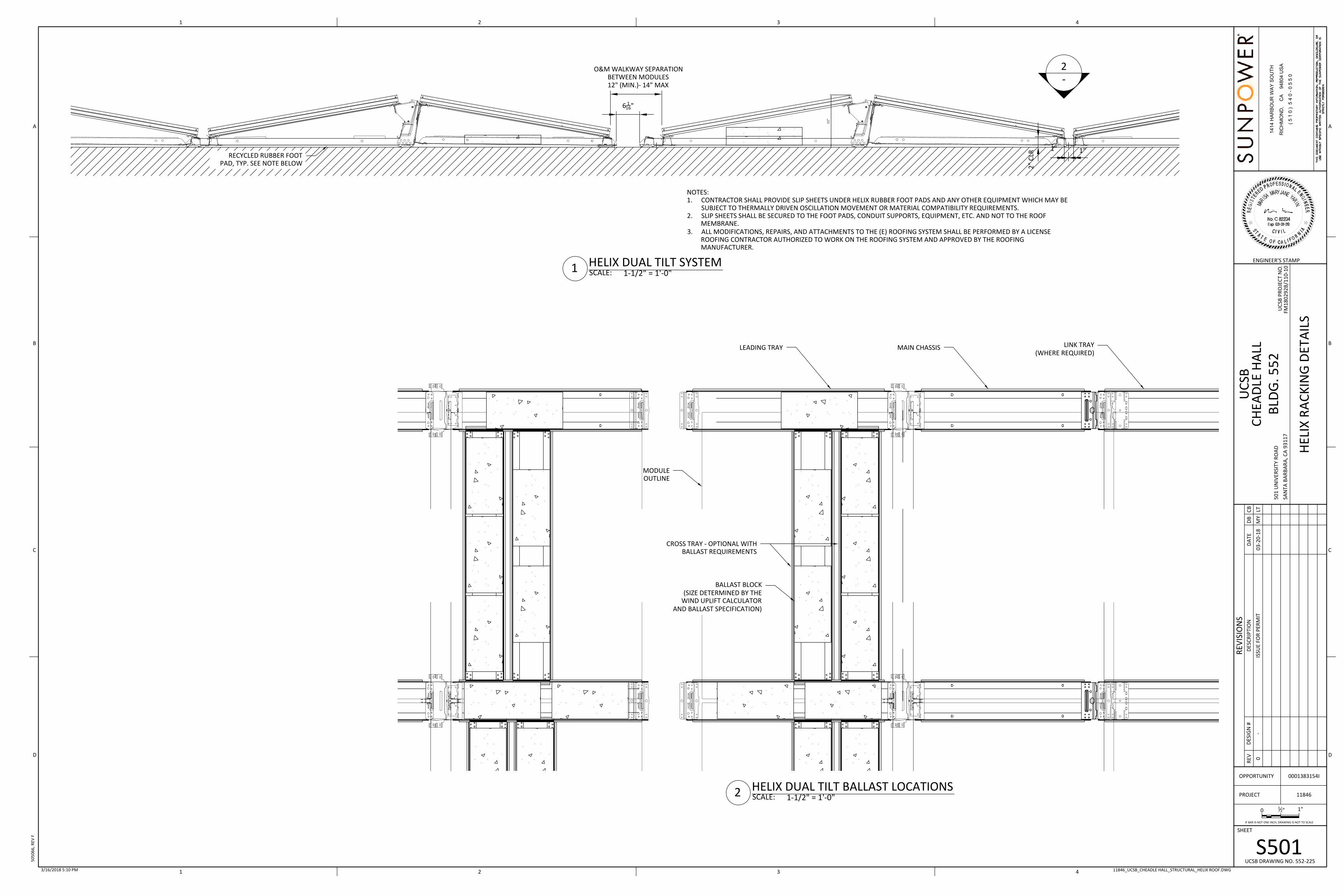
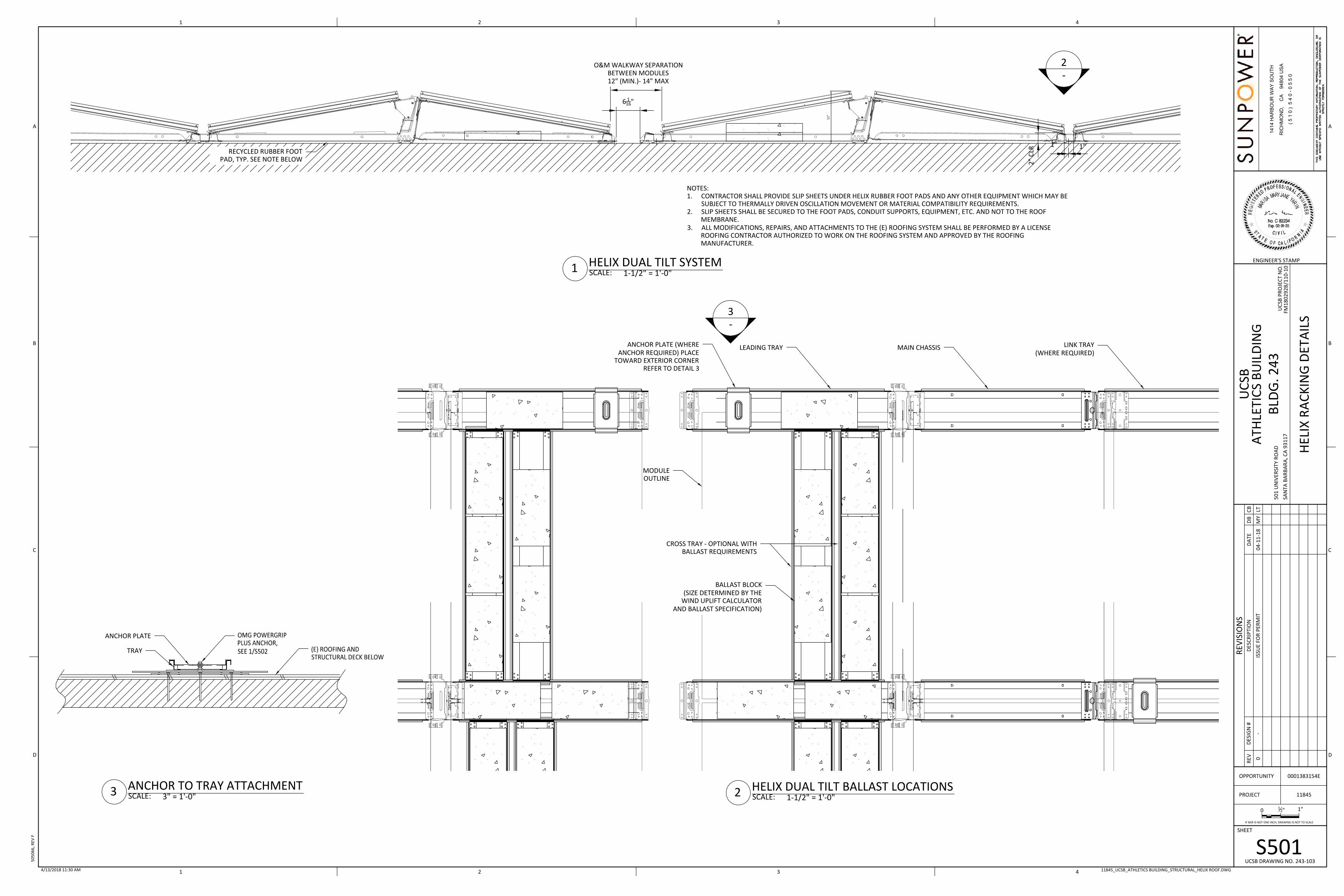
O&M WALKWAY SEPARATIONBETWEEN MODULES12" (MIN.)- 14" MAX
6 116"
1" 1"
11
"
2"
CLRRECYCLED RUBBER FOOT
PAD, TYP. SEE NOTE BELOW
2-
NOTES:1. CONTRACTOR SHALL PROVIDE SLIP SHEETS UNDER HELIX RUBBER FOOT PADS AND ANY OTHER EQUIPMENT WHICH MAY BE
SUBJECT TO THERMALLY DRIVEN OSCILLATION MOVEMENT OR MATERIAL COMPATIBILITY REQUIREMENTS.2. SLIP SHEETS SHALL BE SECURED TO THE FOOT PADS, CONDUIT SUPPORTS, EQUIPMENT, ETC. AND NOT TO THE ROOF
MEMBRANE.3. ALL MODIFICATIONS, REPAIRS, AND ATTACHMENTS TO THE (E) ROOFING SYSTEM SHALL BE PERFORMED BY A LICENSE
ROOFING CONTRACTOR AUTHORIZED TO WORK ON THE ROOFING SYSTEM AND APPROVED BY THE ROOFINGMANUFACTURER.
ANCHOR PLATE (WHEREANCHOR REQUIRED) PLACE
TOWARD EXTERIOR CORNERREFER TO DETAIL 3
LINK TRAY(WHERE REQUIRED)
LEADING TRAY
MODULEOUTLINE
CROSS TRAY - OPTIONAL WITHBALLAST REQUIREMENTS
BALLAST BLOCK(SIZE DETERMINED BY THE
WIND UPLIFT CALCULATORAND BALLAST SPECIFICATION)
MAIN CHASSIS
3-
TRAY
ANCHOR PLATE
SHEET
1414
HA
RB
OU
R W
AY
SO
UTH
RIC
HM
ON
D,
CA
9
4804
US
A
( 5 1
0 )
5 4
0 -
0 5
5 0
REV
DES
IGN
#D
ESC
RIP
TIO
ND
ATE
DB
CB
PROJECT
OPPORTUNITY
REV
ISIO
NS
ENGINEER'S STAMP
1"0 12"
IF BAR IS NOT ONE INCH, DRAWING IS NOT TO SCALE
0-
MY
LT
UC
SBTH
EATE
R A
ND
DA
NC
E5
01
UN
IVER
SITY
RO
AD
SAN
TA B
AR
BA
RA
, CA
93
11
7
11851
0001383154B
4321
4321
A
B
C
D
A
B
C
D
ISSU
E FO
R P
ERM
IT0
3-2
0-1
8
UC
SB P
RO
JEC
T N
O.
FM1
80
29
2B
/11
0-1
0
BLD
G. 2
23
UCSB DRAWING NO. 223-102
S50111851_UCSB_THEATER AND DANCE_STRUCTURAL_HELIX ROOF.DWG3/20/2018 4:38 PM
HEL
IX R
AC
KIN
G D
ETA
ILS
50
50
66
, REV
F
SCALE:1 HELIX DUAL TILT SYSTEM1-1/2" = 1'-0"
SCALE:2 HELIX DUAL TILT BALLAST LOCATIONS1-1/2" = 1'-0"SCALE:3 ANCHOR TO TRAY ATTACHMENT
3" = 1'-0"

SHEET
1414
HA
RB
OU
R W
AY
SO
UTH
RIC
HM
ON
D,
CA
9
4804
US
A
( 5 1
0 )
5 4
0 -
0 5
5 0
REV
DES
IGN
#D
ESC
RIP
TIO
ND
ATE
DB
CB
PROJECT
OPPORTUNITY
REV
ISIO
NS
ENGINEER'S STAMP
1"0 12"
IF BAR IS NOT ONE INCH, DRAWING IS NOT TO SCALE
0-
MY
LT
UC
SBTH
EATE
R A
ND
DA
NC
E5
01
UN
IVER
SITY
RO
AD
SAN
TA B
AR
BA
RA
, CA
93
11
7
11851
0001383154B
4321
4321
A
B
C
D
A
B
C
D
ISSU
E FO
R P
ERM
IT0
3-2
0-1
8
UC
SB P
RO
JEC
T N
O.
FM1
80
29
2B
/11
0-1
0
BLD
G. 2
23
UCSB DRAWING NO. 223-102
S10111851_UCSB_THEATER AND DANCE_STRUCTURAL_HELIX ROOF.DWG3/21/2018 11:19 AM
AR
RA
Y LA
YOU
T -
FIR
E P
LAN
SHADING NOTE:VERIFY ALL MODULES ON ROOF WILL NOT BE SHADED PRIOR TO INSTALLATION BYMEASURING ALL EXISTING OBSTRUCTIONS ON ROOF AND CONFIRMING THEFOLLOWING SETBACK REQUIREMENTS FOR SHADING;
-MINIMUM SETBACK DISTANCE FOR MODULES LOCATED DUE NORTH OFEXISTING OBSTRUCTION SHALL BE NO LESS THAN 1.5X HEIGHT OFOBSTRUCTION.
-MINIMUM SETBACK DISTANCE FOR MODULES LOCATED EAST AND WEST OFEXISTING OBSTRUCTION SHALL BE NO LESS THAN 2X HEIGHT OFOBSTRUCTION.
-RFI ANY MODULE LOCATIONS THAT DO NOT MEET THIS CRITERIA.
CONTRACTOR NOTE: VERIFY ALL DIMENSIONS PRIOR TO INSTALLATION
SUBMITTALS REQUIRED
1. STRUT, METAL FABRICATIONS, & FASTENERS SUPPLIED BY CONTRACTOR2. COLD GALVANIZING COMPOUND3. BALLAST BLOCKS
TYPICAL ROOF SETBACKS MINDISTANCE
HVAC UNIT 4'-0"
SKYLIGHTS 4'-0"
EXHAUST FAN 4'-0"
MECH ACCESSPATHWAYS
4'-0"
TYPICAL WALKWAY MIN CLEARANCEDISTANCE
INTERIOR WALKWAYSMAY ALTERNATE WITH4' WALKWAYS TOPROVIDE "CUTOUTS"EVERY 20'
4' MIN.
MIN. PERMIMETERWALKWAYS
4' MIN.
BALLAST & ANCHOR SUMMARY
SYSTEM WEIGHT 22869 17620
AVERAGE PSF 5.5 4.2
MAX PSF 10.2 10.8
# BALLAST PER ROOF 922 557
# OF ANCHOR PER ROOF 38 66
# MODULE PER ROOF 216 216
TOTAL # OF BALLASTS 1479
TOTAL # OF ANCHORS 104
TOTAL # OF MODULES 432
SITE STRUCTURAL INPUT
WIND SPEED (MPH) 110
EXPOSURE CATEGORY C
TRANSITIONAL DISTANCE (FT) 0
GROUND SNOW LOAD (PSF) 0
SPECTRAL RESPONSE (SDS) 2.00
Ss 2.99
S1 1.07
SIESMIC HAZARD LEVEL 4
SITE CLASS D
SEISMIC IMPT. FACTOR (IP) 1.0
OCCUPANCY CATEGORY II
ROOF SUMMARY ROOF A ROOF B
RACKING TECHNOLOGYHelix
Dual-tiltHelix
Dual-tilt
ANCHOR TYPEOMG
PowerGripPlus
OMGPowerGrip
Plus
BALLAST BLOCK WEIGHT (LBS) 14 14
ROOF MEMBRANESarnafil
PVCSarnafil
PVC
SEISMIC DESIGN PARAMETERS
MAX ROOF SLOPE 1/4: 12 1/4: 12
MIN. OFFSET FROM ROOF EDGE(IN) 37 37
BUILDING DESIGN PARAMETERS
ROOF HEIGHT (FT) 35.6 34.7
ROOF LENGTH (FT) 206.83 183.67
ROOF WIDTH (FT) 67.83 47
PARAPET HEIGHT (FT) 2.08 2.58
SPWR AZIMUTH (DEGREES) 0 0
MAX ALLOWABLE SYSTEMPRESSURE (PSF) 12 12
MAX ALLOWABLE SYSTEMWEIGHT (LBS) 71647 50752
NOTE:CONTRACTOR SHALL PROCURE AND INSTALL ALL REQUIRED SIGNAGE AS SPECIFIED IN SUNPOWERDOCUMENT #505614 REV B, TITLED SPECIFICATION, D&E, SIGNAGE, ELECTRICAL SIGN SPECS. ALL SIGNAGESHALL COMPLY WITH ALL CALIFORNIA STATE FIRE MARSHAL, NFPA 70, AND CAL FIRE SOLAR SIGNAGEREQUIREMENTS.

O&M WALKWAY SEPARATIONBETWEEN MODULES12" (MIN.)- 14" MAX
6 116"
1" 1"
11
"
2"
CLRRECYCLED RUBBER FOOT
PAD, TYP. SEE NOTE BELOW
2-
NOTES:1. CONTRACTOR SHALL PROVIDE SLIP SHEETS UNDER HELIX RUBBER FOOT PADS AND ANY OTHER EQUIPMENT WHICH MAY BE
SUBJECT TO THERMALLY DRIVEN OSCILLATION MOVEMENT OR MATERIAL COMPATIBILITY REQUIREMENTS.2. SLIP SHEETS SHALL BE SECURED TO THE FOOT PADS, CONDUIT SUPPORTS, EQUIPMENT, ETC. AND NOT TO THE ROOF
MEMBRANE.3. ALL MODIFICATIONS, REPAIRS, AND ATTACHMENTS TO THE (E) ROOFING SYSTEM SHALL BE PERFORMED BY A LICENSE
ROOFING CONTRACTOR AUTHORIZED TO WORK ON THE ROOFING SYSTEM AND APPROVED BY THE ROOFINGMANUFACTURER.
ANCHOR PLATE (WHEREANCHOR REQUIRED) PLACE
TOWARD EXTERIOR CORNERREFER TO DETAIL 3
LINK TRAY(WHERE REQUIRED)
LEADING TRAY
MODULEOUTLINE
CROSS TRAY - OPTIONAL WITHBALLAST REQUIREMENTS
BALLAST BLOCK(SIZE DETERMINED BY THE
WIND UPLIFT CALCULATORAND BALLAST SPECIFICATION)
MAIN CHASSIS
3-
TRAY
ANCHOR PLATE
SHEET
1414
HA
RB
OU
R W
AY
SO
UTH
RIC
HM
ON
D,
CA
9
4804
US
A
( 5 1
0 )
5 4
0 -
0 5
5 0
REV
DES
IGN
#D
ESC
RIP
TIO
ND
ATE
DB
CB
PROJECT
OPPORTUNITY
REV
ISIO
NS
ENGINEER'S STAMP
1"0 12"
IF BAR IS NOT ONE INCH, DRAWING IS NOT TO SCALE
0-
LTR
M
UC
SBD
AV
IDSO
N L
IBR
AR
Y5
01
UN
IVER
SITY
RO
AD
SAN
TA B
AR
BA
RA
, CA
93
11
7
11847
4321
4321
A
B
C
D
A
B
C
D
0001383154D
ISSU
E FO
R P
ERM
IT0
3-2
0-1
8
UC
SB P
RO
JEC
T N
O.
FM1
80
29
2B
/11
0-1
0
BLD
G. 5
25
UCSB DRAWING NO. 525-605
S50111847_UCSB_DAVIDSON LIBRARY_STRUCTURAL_HELIX ROOF.DWG3/21/2018 11:24 AM
HEL
IX R
AC
KIN
G D
ETA
ILS
- H
DT
50
50
66
, REV
F
SCALE:1 HELIX DUAL TILT SYSTEM1-1/2" = 1'-0"
SCALE:2 HELIX DUAL TILT BALLAST LOCATIONS1-1/2" = 1'-0"SCALE:3 ANCHOR TO TRAY ATTACHMENT
3" = 1'-0"
SHEET
1414
HA
RB
OU
R W
AY
SO
UTH
RIC
HM
ON
D,
CA
9
4804
US
A
( 5 1
0 )
5 4
0 -
0 5
5 0
REV
DES
IGN
#D
ESC
RIP
TIO
ND
ATE
DB
CB
PROJECT
OPPORTUNITY
REV
ISIO
NS
ENGINEER'S STAMP
1"0 12"
IF BAR IS NOT ONE INCH, DRAWING IS NOT TO SCALE
0-
LTR
M
UC
SBD
AV
IDSO
N L
IBR
AR
Y5
01
UN
IVER
SITY
RO
AD
SAN
TA B
AR
BA
RA
, CA
93
11
7
11847
4321
4321
A
B
C
D
A
B
C
D
0001383154D
ISSU
E FO
R P
ERM
IT0
3-2
0-1
8
UC
SB P
RO
JEC
T N
O.
FM1
80
29
2B
/11
0-1
0
BLD
G. 5
25
UCSB DRAWING NO. 525-605
S10111847_UCSB_DAVIDSON LIBRARY_STRUCTURAL_HELIX ROOF.DWG3/21/2018 11:23 AM
AR
RA
Y LA
YOU
T -
FIR
E P
LAN
TYPICAL ROOF SETBACKS MINDISTANCE
HVAC UNIT 4'-0"
SKYLIGHTS 4'-0"
EXHAUST FAN 4'-0"
MECH ACCESSPATHWAYS
4'-0"
TYPICAL WALKWAY MIN CLEARANCEDISTANCE
INTERIOR WALKWAYSMAY ALTERNATE WITH4' WALKWAYS TOPROVIDE "CUTOUTS"EVERY 20'
4' MIN.
MIN. PERMIMETERWALKWAYS
4' MIN.
BALLAST & ANCHOR SUMMARY
SYSTEM WEIGHT 11854 9827 9909 19838 8003
AVERAGE PSF 4.3 4.2 6.3 4.2 4.1
MAX PSF 8.5 8.2 8.5 10.2 6.1
# BALLAST PER ROOF 379 315 488 769 249
# OF ANCHOR PER ROOF 52 42 0 80 0
# MODULE PER ROOF 144 120 60 180 100
TOTAL # OF BALLASTS 2200
TOTAL # OF ANCHORS 174
TOTAL # OF MODULES 604
SITE STRUCTURAL INPUT
WIND SPEED (MPH) 115
EXPOSURE CATEGORY C to B
TRANSITIONAL DISTANCE (FT) 1200
GROUND SNOW LOAD (PSF) 0
SPECTRAL RESPONSE (SDS) 1.99
Ss 2.99
S1 1.07
SIESMIC HAZARD LEVEL 4
SITE CLASS D
SEISMIC IMPT. FACTOR (IP) 1.0
OCCUPANCY CATEGORY III
ROOF SUMMARY ROOF A ROOF B ROOF C ROOF D ROOF E
RACKING TECHNOLOGYHELIX
DUAL-TILT
HELIXDUAL-TI
LT
HELIXSINGLE-
TILT
HELIXSINGLE-
TILT
HELIXDUAL-TILT
ANCHOR TYPEOMG
PowerGrip Plus
OMGPowerGrip Plus
OMGPowerGrip Plus
OMGPowerGrip Plus
OMGPowerGrip
Plus
BALLAST BLOCK WEIGHT (LBS) 14 14 14 14 14
ROOF MEMBRANESarnafil
PVCSarnafil
PVCSarnafil
PVCSarnafil
PVCSarnafil
PVC
SEISMIC DESIGN PARAMETERS
MAX ROOF SLOPE 1/2:12 1/2:12 1/4: 12 1/2:12 1/2:12
MIN. OFFSET FROM ROOF EDGE (IN) 50 50 47 67 50
BUILDING DESIGN PARAMETERS
ROOF HEIGHT (FT) 51.83 45.84 31.91 27.81 27.81
ROOF LENGTH (FT) 234 234 330 330 330
ROOF WIDTH (FT) 73 73 240 240 240
PARAPET HEIGHT (FT) 0 2.75 3.67 6.08 6.08
SPWR AZIMUTH (DEGREES) 0 0 0 0 0
MAX ALLOWABLE SYSTEM PRESSURE(PSF) 12 12 12 12 12
MAX ALLOWABLE SYSTEM WEIGHT(LBS) 152365 152365 27680 193596 193596
SHADING NOTE:VERIFY ALL MODULES ON ROOF WILL NOT BE SHADED PRIOR TO INSTALLATION BYMEASURING ALL EXISTING OBSTRUCTIONS ON ROOF AND CONFIRMING THEFOLLOWING SETBACK REQUIREMENTS FOR SHADING;
-MINIMUM SETBACK DISTANCE FOR MODULES LOCATED DUE NORTH OFEXISTING OBSTRUCTION SHALL BE NO LESS THAN 1.5X HEIGHT OFOBSTRUCTION.
-MINIMUM SETBACK DISTANCE FOR MODULES LOCATED EAST AND WEST OFEXISTING OBSTRUCTION SHALL BE NO LESS THAN 2X HEIGHT OFOBSTRUCTION.
-RFI ANY MODULE LOCATIONS THAT DO NOT MEET THIS CRITERIA.
CONTRACTOR NOTE: VERIFY ALL DIMENSIONS PRIOR TO INSTALLATION
SUBMITTALS REQUIRED
1. STRUT, METAL FABRICATIONS, & FASTENERS SUPPLIED BY CONTRACTOR2. COLD GALVANIZING COMPOUND3. BALLAST BLOCKS
NOTE:CONTRACTOR SHALL PROCURE AND INSTALL ALL REQUIRED SIGNAGE AS SPECIFIED IN SUNPOWERDOCUMENT #505614 REV B, TITLED SPECIFICATION, D&E, SIGNAGE, ELECTRICAL SIGN SPECS. ALL SIGNAGESHALL COMPLY WITH ALL CALIFORNIA STATE FIRE MARSHAL, NFPA 70, AND CAL FIRE SOLAR SIGNAGEREQUIREMENTS.
O&M WALKWAY SEPARATIONBETWEEN MODULES12" (MIN.)- 14" MAX
6 116"
1" 1"
11
"
2"
CLRRECYCLED RUBBER FOOT
PAD, TYP. SEE NOTE BELOW
2-
NOTES:1. CONTRACTOR SHALL PROVIDE SLIP SHEETS UNDER HELIX RUBBER FOOT PADS AND ANY OTHER EQUIPMENT WHICH MAY BE
SUBJECT TO THERMALLY DRIVEN OSCILLATION MOVEMENT OR MATERIAL COMPATIBILITY REQUIREMENTS.2. SLIP SHEETS SHALL BE SECURED TO THE FOOT PADS, CONDUIT SUPPORTS, EQUIPMENT, ETC. AND NOT TO THE ROOF
MEMBRANE.3. ALL MODIFICATIONS, REPAIRS, AND ATTACHMENTS TO THE (E) ROOFING SYSTEM SHALL BE PERFORMED BY A LICENSE
ROOFING CONTRACTOR AUTHORIZED TO WORK ON THE ROOFING SYSTEM AND APPROVED BY THE ROOFINGMANUFACTURER.
LINK TRAY(WHERE REQUIRED)
LEADING TRAY
MODULEOUTLINE
CROSS TRAY - OPTIONAL WITHBALLAST REQUIREMENTS
BALLAST BLOCK(SIZE DETERMINED BY THE
WIND UPLIFT CALCULATORAND BALLAST SPECIFICATION)
MAIN CHASSIS
SHEET
1414
HA
RB
OU
R W
AY
SO
UTH
RIC
HM
ON
D,
CA
9
4804
US
A
( 5 1
0 )
5 4
0 -
0 5
5 0
REV
DES
IGN
#D
ESC
RIP
TIO
ND
ATE
DB
CB
PROJECT
OPPORTUNITY
REV
ISIO
NS
ENGINEER'S STAMP
1"0 12"
IF BAR IS NOT ONE INCH, DRAWING IS NOT TO SCALE
0-
MY
LT
UC
SBC
HEA
DLE
HA
LL5
01
UN
IVER
SITY
RO
AD
SAN
TA B
AR
BA
RA
, CA
93
11
7
11846
4321
4321
A
B
C
D
A
B
C
D
0001383154I
ISSU
E FO
R P
ERM
IT0
3-2
0-1
8
UC
SB P
RO
JEC
T N
O.
FM1
80
29
2B
/11
0-1
0
BLD
G. 5
52
UCSB DRAWING NO. 552-225
S50111846_UCSB_CHEADLE HALL_STRUCTURAL_HELIX ROOF.DWG3/16/2018 5:10 PM
HEL
IX R
AC
KIN
G D
ETA
ILS
50
50
66
, REV
F
SCALE:1 HELIX DUAL TILT SYSTEM1-1/2" = 1'-0"
SCALE:2 HELIX DUAL TILT BALLAST LOCATIONS1-1/2" = 1'-0"

SHEET
1414
HA
RB
OU
R W
AY
SO
UTH
RIC
HM
ON
D,
CA
9
4804
US
A
( 5 1
0 )
5 4
0 -
0 5
5 0
REV
DES
IGN
#D
ESC
RIP
TIO
ND
ATE
DB
CB
PROJECT
OPPORTUNITY
REV
ISIO
NS
ENGINEER'S STAMP
1"0 12"
IF BAR IS NOT ONE INCH, DRAWING IS NOT TO SCALE
0-
MY
LT
UC
SBC
HEA
DLE
HA
LL5
01
UN
IVER
SITY
RO
AD
SAN
TA B
AR
BA
RA
, CA
93
11
7
11846
4321
4321
A
B
C
D
A
B
C
D
0001383154I
ISSU
E FO
R P
ERM
IT0
3-2
0-1
8
UC
SB P
RO
JEC
T N
O.
FM1
80
29
2B
/11
0-1
0
BLD
G. 5
52
UCSB DRAWING NO. 552-225
S10111846_UCSB_CHEADLE HALL_STRUCTURAL_HELIX ROOF.DWG3/21/2018 11:17 AM
AR
RA
Y LA
YOU
T -
FIR
E P
LAN
SHADING NOTE:VERIFY ALL MODULES ON ROOF WILL NOT BE SHADED PRIOR TO INSTALLATION BYMEASURING ALL EXISTING OBSTRUCTIONS ON ROOF AND CONFIRMING THEFOLLOWING SETBACK REQUIREMENTS FOR SHADING;
-MINIMUM SETBACK DISTANCE FOR MODULES LOCATED DUE NORTH OFEXISTING OBSTRUCTION SHALL BE NO LESS THAN 1.5X HEIGHT OFOBSTRUCTION.
-MINIMUM SETBACK DISTANCE FOR MODULES LOCATED EAST AND WEST OFEXISTING OBSTRUCTION SHALL BE NO LESS THAN 2X HEIGHT OFOBSTRUCTION.
-RFI ANY MODULE LOCATIONS THAT DO NOT MEET THIS CRITERIA.
CONTRACTOR NOTE: VERIFY ALL DIMENSIONS PRIOR TO INSTALLATION
SUBMITTALS REQUIRED
1. STRUT, METAL FABRICATIONS, & FASTENERS SUPPLIED BY CONTRACTOR2. COLD GALVANIZING COMPOUND3. BALLAST BLOCKS
TYPICAL ROOF SETBACKS MINDISTANCE
HVAC UNIT 4'-0"
SKYLIGHTS 4'-0"
EXHAUST FAN 4'-0"
MECH ACCESSPATHWAYS
4'-0"
TYPICAL WALKWAY MIN CLEARANCEDISTANCE
INTERIOR WALKWAYSMAY ALTERNATE WITH4' WALKWAYS TOPROVIDE "CUTOUTS"EVERY 20'
4' MIN.
MIN. PERMIMETERWALKWAYS
4' MIN.
BALLAST & ANCHOR SUMMARY
SYSTEM WEIGHT 32814
AVERAGE PSF 3.1
MAX PSF 7.2
# BALLAST PER ROOF 586
# OF ANCHOR PER ROOF 0
# MODULE PER ROOF 552
SITE STRUCTURAL INPUT
WIND SPEED (MPH) 110
EXPOSURE CATEGORY C
TRANSITIONAL DISTANCE (FT) 0
GROUND SNOW LOAD (PSF) 0
SPECTRAL RESPONSE (SDS) 1.98
Ss 2.98
S1 1.06
SIESMIC HAZARD LEVEL 4
SITE CLASS D
SEISMIC IMPT. FACTOR (IP) 1.0
OCCUPANCY CATEGORY II
ROOF SUMMARY ROOF A
RACKING TECHNOLOGY HELIX DUAL-TILT
ANCHOR TYPE OMG PowerGrip Plus
BALLAST BLOCK WEIGHT (LBS) 14
ROOF MEMBRANE Sarnafil PVC
SEISMIC DESIGN PARAMETERS
MAX ROOF SLOPE 1/4: 12
MIN. OFFSET FROM ROOF EDGE(IN) 37
BUILDING DESIGN PARAMETERS
ROOF HEIGHT (FT) 15
ROOF LENGTH (FT) 233.08
ROOF WIDTH (FT) 175.08
PARAPET HEIGHT (FT) 1.67
SPWR AZIMUTH (DEGREES) 0
MAX ALLOWABLE SYSTEMPRESSURE (PSF) 12
MAX ALLOWABLE SYSTEMWEIGHT (LBS) 131520
NOTE:CONTRACTOR SHALL PROCURE AND INSTALL ALL REQUIRED SIGNAGE AS SPECIFIED IN SUNPOWERDOCUMENT #505614 REV B, TITLED SPECIFICATION, D&E, SIGNAGE, ELECTRICAL SIGN SPECS. ALL SIGNAGESHALL COMPLY WITH ALL CALIFORNIA STATE FIRE MARSHAL, NFPA 70, AND CAL FIRE SOLAR SIGNAGEREQUIREMENTS.
O&M WALKWAY SEPARATIONBETWEEN MODULES12" (MIN.)- 14" MAX
6 116"
1" 1"
11
"
2"
CLRRECYCLED RUBBER FOOT
PAD, TYP. SEE NOTE BELOW
2-
NOTES:1. CONTRACTOR SHALL PROVIDE SLIP SHEETS UNDER HELIX RUBBER FOOT PADS AND ANY OTHER EQUIPMENT WHICH MAY BE
SUBJECT TO THERMALLY DRIVEN OSCILLATION MOVEMENT OR MATERIAL COMPATIBILITY REQUIREMENTS.2. SLIP SHEETS SHALL BE SECURED TO THE FOOT PADS, CONDUIT SUPPORTS, EQUIPMENT, ETC. AND NOT TO THE ROOF
MEMBRANE.3. ALL MODIFICATIONS, REPAIRS, AND ATTACHMENTS TO THE (E) ROOFING SYSTEM SHALL BE PERFORMED BY A LICENSE
ROOFING CONTRACTOR AUTHORIZED TO WORK ON THE ROOFING SYSTEM AND APPROVED BY THE ROOFINGMANUFACTURER.
ANCHOR PLATE (WHEREANCHOR REQUIRED) PLACE
TOWARD EXTERIOR CORNERREFER TO DETAIL 3
LINK TRAY(WHERE REQUIRED)
LEADING TRAY
MODULEOUTLINE
CROSS TRAY - OPTIONAL WITHBALLAST REQUIREMENTS
BALLAST BLOCK(SIZE DETERMINED BY THE
WIND UPLIFT CALCULATORAND BALLAST SPECIFICATION)
MAIN CHASSIS
3-
TRAY
ANCHOR PLATE
SHEET
1414
HA
RB
OU
R W
AY
SO
UTH
RIC
HM
ON
D,
CA
9
4804
US
A
( 5 1
0 )
5 4
0 -
0 5
5 0
REV
DES
IGN
#D
ESC
RIP
TIO
ND
ATE
DB
CB
PROJECT
OPPORTUNITY
REV
ISIO
NS
ENGINEER'S STAMP
1"0 12"
IF BAR IS NOT ONE INCH, DRAWING IS NOT TO SCALE
0-
MY
LT
UC
SBA
THLE
TIC
S B
UIL
DIN
G5
01
UN
IVER
SITY
RO
AD
SAN
TA B
AR
BA
RA
, CA
93
11
7
11845
4321
4321
A
B
C
D
A
B
C
D
0001383154E
ISSU
E FO
R P
ERM
IT0
4-1
1-1
8
UC
SB P
RO
JEC
T N
O.
FM1
80
29
2B
/11
0-1
0
BLD
G. 2
43
UCSB DRAWING NO. 243-103
S50111845_UCSB_ATHLETICS BUILDING_STRUCTURAL_HELIX ROOF.DWG4/13/2018 11:30 AM
HEL
IX R
AC
KIN
G D
ETA
ILS
50
50
66
, REV
F
SCALE:1 HELIX DUAL TILT SYSTEM1-1/2" = 1'-0"
SCALE:2 HELIX DUAL TILT BALLAST LOCATIONS1-1/2" = 1'-0"SCALE:3 ANCHOR TO TRAY ATTACHMENT
3" = 1'-0"
SHEET
1414
HA
RB
OU
R W
AY
SO
UTH
RIC
HM
ON
D,
CA
9
4804
US
A
( 5 1
0 )
5 4
0 -
0 5
5 0
REV
DES
IGN
#D
ESC
RIP
TIO
ND
ATE
DB
CB
PROJECT
OPPORTUNITY
REV
ISIO
NS
ENGINEER'S STAMP
1"0 12"
IF BAR IS NOT ONE INCH, DRAWING IS NOT TO SCALE
0-
MY
LT
UC
SBA
THLE
TIC
S B
UIL
DIN
G5
01
UN
IVER
SITY
RO
AD
SAN
TA B
AR
BA
RA
, CA
93
11
7
11845
4321
4321
A
B
C
D
A
B
C
D
0001383154E
ISSU
E FO
R P
ERM
IT0
4-1
1-1
8
UC
SB P
RO
JEC
T N
O.
FM1
80
29
2B
/11
0-1
0
BLD
G. 2
43
UCSB DRAWING NO. 243-103
S10111845_UCSB_ATHLETICS BUILDING_STRUCTURAL_HELIX ROOF.DWG4/13/2018 12:00 PM
AR
RA
Y LA
YOU
T -
FIR
E P
LAN
SHADING NOTE:VERIFY ALL MODULES ON ROOF WILL NOT BE SHADED PRIOR TO INSTALLATION BYMEASURING ALL EXISTING OBSTRUCTIONS ON ROOF AND CONFIRMING THEFOLLOWING SETBACK REQUIREMENTS FOR SHADING;
-MINIMUM SETBACK DISTANCE FOR MODULES LOCATED DUE NORTH OFEXISTING OBSTRUCTION SHALL BE NO LESS THAN 1.5X HEIGHT OFOBSTRUCTION.
-MINIMUM SETBACK DISTANCE FOR MODULES LOCATED EAST AND WEST OFEXISTING OBSTRUCTION SHALL BE NO LESS THAN 2X HEIGHT OFOBSTRUCTION.
-RFI ANY MODULE LOCATIONS THAT DO NOT MEET THIS CRITERIA.
CONTRACTOR NOTE: VERIFY ALL DIMENSIONS PRIOR TO INSTALLATION
SUBMITTALS REQUIRED
1. STRUT, METAL FABRICATIONS, & FASTENERS SUPPLIED BY CONTRACTOR2. COLD GALVANIZING COMPOUND3. BALLAST BLOCKS
TYPICAL ROOF SETBACKS MINDISTANCE
HVAC UNIT 4'-0"
SKYLIGHTS 4'-0"
EXHAUST FAN 4'-0"
MECH ACCESSPATHWAYS
4'-0"
TYPICAL WALKWAY MIN CLEARANCEDISTANCE
INTERIOR WALKWAYSMAY ALTERNATE WITH4' WALKWAYS TOPROVIDE "CUTOUTS"EVERY 20'
4' MIN.
MIN. PERMIMETERWALKWAYS
4' MIN.
BALLAST & ANCHOR SUMMARY
SYSTEM WEIGHT 18854 6572
AVERAGE PSF 3.4 2.4
MAX PSF 8.2 2.6
# BALLAST PER ROOF 426 14
# OF ANCHOR PER ROOF 83 58
# MODULE PER ROOF 288 144
TOTAL # OF BALLASTS 440
TOTAL # OF ANCHORS 141
TOTAL # OF MODULES 432
SITE STRUCTURAL INPUT
WIND SPEED (MPH) 110
EXPOSURE CATEGORY C
TRANSITIONAL DISTANCE (FT) 0
GROUND SNOW LOAD (PSF) 0
SPECTRAL RESPONSE (SDS) 2.00
Ss 2.99
S1 1.07
SIESMIC HAZARD LEVEL 4
SITE CLASS D
SEISMIC IMPT. FACTOR (IP) 1.0
OCCUPANCY CATEGORY II
ROOF SUMMARY ROOF A ROOF B
RACKING TECHNOLOGYHELIX
DUAL-TILTHELIX
DUAL-TILT
ANCHOR TYPEOMG
PowerGripPlus
OMGPowerGrip
Plus
BALLAST BLOCK WEIGHT (LBS) 14 14
ROOF MEMBRANE Sarnafil PVCSarnafil
PVC
SEISMIC DESIGN PARAMETERS
MAX ROOF SLOPE 1/4: 12 1/2:12
MIN. OFFSET FROM ROOF EDGE(IN) 37 50
BUILDING DESIGN PARAMETERS
ROOF HEIGHT (FT) 25.62 32
ROOF LENGTH (FT) 204.42 86
ROOF WIDTH (FT) 114.08 65.9167
PARAPET HEIGHT (FT) 0.5 0.83
SPWR AZIMUTH (DEGREES) 0 0
MAX ALLOWABLE SYSTEMPRESSURE (PSF) 10 4
MAX ALLOWABLE SYSTEMWEIGHT (LBS) 23802 7213
NOTE:CONTRACTOR SHALL PROCURE AND INSTALL ALL REQUIRED SIGNAGE AS SPECIFIEDIN SUNPOWER DOCUMENT #505614 REV B, TITLED SPECIFICATION, D&E, SIGNAGE,ELECTRICAL SIGN SPECS. ALL SIGNAGE SHALL COMPLY WITH ALL CALIFORNIA STATEFIRE MARSHAL, NFPA 70, AND CAL FIRE SOLAR SIGNAGE REQUIREMENTS.
ROOF A
ROOF B

O&M WALKWAY SEPARATIONBETWEEN MODULES12" (MIN.)- 14" MAX
6 116"
1" 1"
11
"
2"
CLRRECYCLED RUBBER FOOT
PAD, TYP. SEE NOTE BELOW
2-
NOTES:1. CONTRACTOR SHALL PROVIDE SLIP SHEETS UNDER HELIX RUBBER FOOT PADS AND ANY OTHER EQUIPMENT WHICH MAY BE
SUBJECT TO THERMALLY DRIVEN OSCILLATION MOVEMENT OR MATERIAL COMPATIBILITY REQUIREMENTS.2. SLIP SHEETS SHALL BE SECURED TO THE FOOT PADS, CONDUIT SUPPORTS, EQUIPMENT, ETC. AND NOT TO THE ROOF
MEMBRANE.3. ALL MODIFICATIONS, REPAIRS, AND ATTACHMENTS TO THE (E) ROOFING SYSTEM SHALL BE PERFORMED BY A LICENSE
ROOFING CONTRACTOR AUTHORIZED TO WORK ON THE ROOFING SYSTEM AND APPROVED BY THE ROOFINGMANUFACTURER.
ANCHOR PLATE (WHEREANCHOR REQUIRED) PLACE
TOWARD EXTERIOR CORNERREFER TO DETAIL 3
LINK TRAY(WHERE REQUIRED)
LEADING TRAY
MODULEOUTLINE
CROSS TRAY - OPTIONAL WITHBALLAST REQUIREMENTS
BALLAST BLOCK(SIZE DETERMINED BY THE
WIND UPLIFT CALCULATORAND BALLAST SPECIFICATION)
MAIN CHASSIS
3-
TRAY
ANCHOR PLATE
SHEET
1414
HA
RB
OU
R W
AY
SO
UTH
RIC
HM
ON
D,
CA
9
4804
US
A
( 5 1
0 )
5 4
0 -
0 5
5 0
REV
DES
IGN
#D
ESC
RIP
TIO
ND
ATE
DB
CB
PROJECT
OPPORTUNITY
REV
ISIO
NS
ENGINEER'S STAMP
1"0 12"
IF BAR IS NOT ONE INCH, DRAWING IS NOT TO SCALE
0-
MY
LT
UC
SBA
RTS
BU
ILD
ING
50
1 U
NIV
ERSI
TY R
OA
D
SAN
TA B
AR
BA
RA
, CA
93
11
7
11844
4321
4321
A
B
C
D
A
B
C
D
0001383154H
ISSU
E FO
R P
ERM
IT0
2-2
2-1
8
UC
SB P
RO
JEC
T N
O.
FM1
80
29
2B
/11
0-1
0
BLD
G. 5
34
UCSB DRAWING NO. 534-303
S50111844_UCSB_ARTS BUILDING_STRUCTURAL_HELIX ROOF.DWG2/22/2018 4:52 PM
HEL
IX R
AC
KIN
G D
ETA
ILS
50
50
66
, REV
F
SCALE:1 HELIX DUAL TILT SYSTEM1-1/2" = 1'-0"
SCALE:2 HELIX DUAL TILT BALLAST LOCATIONS1-1/2" = 1'-0"SCALE:3 ANCHOR TO TRAY ATTACHMENT
3" = 1'-0"

SHEET
1414
HA
RB
OU
R W
AY
SO
UTH
RIC
HM
ON
D,
CA
9
4804
US
A
( 5 1
0 )
5 4
0 -
0 5
5 0
REV
DES
IGN
#D
ESC
RIP
TIO
ND
ATE
DB
CB
PROJECT
OPPORTUNITY
REV
ISIO
NS
ENGINEER'S STAMP
1"0 12"
IF BAR IS NOT ONE INCH, DRAWING IS NOT TO SCALE
0-
MY
LT
UC
SBA
RTS
BU
ILD
ING
50
1 U
NIV
ERSI
TY R
OA
D
SAN
TA B
AR
BA
RA
, CA
93
11
7
11844
4321
4321
A
B
C
D
A
B
C
D
0001383154H
ISSU
E FO
R P
ERM
IT0
2-2
2-1
8
UC
SB P
RO
JEC
T N
O.
FM1
80
29
2B
/11
0-1
0
BLD
G. 5
34
UCSB DRAWING NO. 534-303
1-
MY
LTFI
RE
MA
RSH
AL
REV
ISIO
NS
03
-21
-18
S10111844_UCSB_ARTS BUILDING_STRUCTURAL_HELIX ROOF.DWG3/21/2018 10:52 AM
AR
RA
Y LA
YOU
T -
FIR
E P
LAN
SHADING NOTE:VERIFY ALL MODULES ON ROOF WILL NOT BE SHADED PRIOR TO INSTALLATION BYMEASURING ALL EXISTING OBSTRUCTIONS ON ROOF AND CONFIRMING THEFOLLOWING SETBACK REQUIREMENTS FOR SHADING;
-MINIMUM SETBACK DISTANCE FOR MODULES LOCATED DUE NORTH OFEXISTING OBSTRUCTION SHALL BE NO LESS THAN 1.5X HEIGHT OFOBSTRUCTION.
-MINIMUM SETBACK DISTANCE FOR MODULES LOCATED EAST AND WEST OFEXISTING OBSTRUCTION SHALL BE NO LESS THAN 2X HEIGHT OFOBSTRUCTION.
-RFI ANY MODULE LOCATIONS THAT DO NOT MEET THIS CRITERIA.
CONTRACTOR NOTE: VERIFY ALL DIMENSIONS PRIOR TO INSTALLATION
SUBMITTALS REQUIRED
1. CONCRETE MIX DESIGN(S)2. REBAR SHOP DRAWINGS3. STRUT, METAL FABRICATIONS, & FASTENERS SUPPLIED BY CONTRACTOR4. COLD GALVANIZING COMPOUND5. BALLAST BLOCKS
TYPICAL ROOF SETBACKS MINDISTANCE
HVAC UNIT 4'-0"
SKYLIGHTS 4'-0"
EXHAUST FAN 4'-0"
MECH ACCESSPATHWAYS
4'-0"
TYPICAL WALKWAY MIN CLEARANCEDISTANCE
INTERIOR WALKWAYSMAY ALTERNATE WITH4' WALKWAYS TOPROVIDE "CUTOUTS"EVERY 20'
4' MIN.
MIN. PERMIMETERWALKWAYS
4' MIN.
BALLAST & ANCHOR SUMMARY
SYSTEM WEIGHT 20363 20708
AVERAGE PSF 4.0 3.4
MAX PSF 10.2 9.1
# BALLAST PER ROOF 591 472
# OF ANCHOR PER ROOF 88 92
# MODULE PER ROOF 264 312
TOTAL # OF BALLASTS 1063
TOTAL # OF ANCHORS 180
TOTAL # OF MODULES 576
SITE STRUCTURAL INPUT
WIND SPEED (MPH) 110
EXPOSURE CATEGORY C
TRANSITIONAL DISTANCE (FT) 0
GROUND SNOW LOAD (PSF) 0
SPECTRAL RESPONSE (SDS) 2.00
Ss 3.00
S1 1.07
SIESMIC HAZARD LEVEL 4
SITE CLASS D
SEISMIC IMPT. FACTOR (IP) 1.0
OCCUPANCY CATEGORY II
ROOF SUMMARY ROOF A ROOF B
RACKING TECHNOLOGYHELIX
DUAL-TILTHELIX
DUAL-TILT
ANCHOR TYPEOMG
PowerGripPlus
OMGPowerGrip
Plus
BALLAST BLOCK WEIGHT (LBS) 14 14
ROOF MEMBRANEJohns
ManvillePVC
JohnsManville
PVC
SEISMIC DESIGN PARAMETERS
MAX ROOF SLOPE 1:12 1:12
MIN. OFFSET FROM ROOF EDGE(IN) 87 87
BUILDING DESIGN PARAMETERS
ROOF HEIGHT (FT) 30.67 30.67
ROOF LENGTH (FT) 179.25 179.25
ROOF WIDTH (FT) 176.25 176.25
PARAPET HEIGHT (FT) 2 2
SPWR AZIMUTH (DEGREES) 0 0
MAX ALLOWABLE SYSTEMPRESSURE (PSF) 12 12
MAX ALLOWABLE SYSTEMWEIGHT (LBS) 56555 58129
ROOF B
ROOF A
NOTE:CONTRACTOR SHALL PROCURE AND INSTALL ALL REQUIRED SIGNAGE AS SPECIFIED IN SUNPOWERDOCUMENT #505614 REV B, TITLED SPECIFICATION, D&E, SIGNAGE, ELECTRICAL SIGN SPECS. ALL SIGNAGESHALL COMPLY WITH ALL CALIFORNIA STATE FIRE MARSHAL, NFPA 70, AND CAL FIRE SOLAR SIGNAGEREQUIREMENTS.
1