Embed Size (px)
Citation preview

UCRL-JC-121400 PREPRINT
. . .. :
Mechanism of D u d e Rupture .in the AYSapphire System Elucidated Using X-Ray Tomographic Microscopy
I, W.E.King G.H. C*pbelI
D.L. Haupt . J.H. h e y . . _ '
R A R i d d l e . . . . . .
. . . . . . . . . . . . . . . . . . . . . . . . . . . . . . . . . . . . . . . . . . . . . . . . . . . . . . . . . . . . . . . . . . . .. . .
. . . , . : *.., * . . W.L. wien. . . . . ' . . . . . . . . . . . . . . . . . . . . . . . . : ~ :.:;, .,;.:;.. . . . . . ... . . 1 . . . .- . .. . .
This paper was prepared for submittal to Fall Meeting of the Materials Research Society
Boston, MA November 27-December 2,1995
December 18; 1995
Thisisa preprint ofa paper intended for publicationin a journal orpmceedings. Since I changes may be made before publication, this preprint is made available with the
undefstanding that it will not be dted or reproduced without the permission of the .
' . I author. . . . . .
. . . . . . . . . . . . . " . . . . . . . . . . . . . . . . . .. . . . . . . . . . . . . . . . . . * .. : '.Z.. - . . . . . . . . . . , . . ,.
. . . . . . . . . . . . . . ., . .
..:.. 7 . . . . . . . . . . . . . . . . . . . . .
: .,. . . . . . . . .:
. .
.I. . . . . . . . . . .
. . . DISCLAIMER
. . . : l . . : , : Y . . . .
This report was prepared as an account of work sponsored by an agency of the United States Government. Neither the United States Government nor any agency thereof, nor any of their employees, makes any warranty, express or implied, or assumes any legal liability or responsi- bility for the accuracy, completeness, or usefulness of any information, apparatus, product, or '
process disclosed, or represents that its use would not infringe privately owned rights. Refer- ence herein to any specific commercial product, process, or service by trade name, trademark, manufacturer, or otherwise does not necessarily constitute or imply its endorsement, recorn- mendation, or favoring by the United States Government or any agency thereof. The views and opinions of authors expressed herein do not necessarily state or reflect those of the
,
. . . .
. . . . . .. . . . . . . . . . I. : . ' . ~. " . . . . . . . . . . . . . . . .
. . . . . . . . . . . . . .
. . . . . . . _ . .
i ' . .I
. .
DlscLAIMER
Portions of this document may be illegible in electronic image products. Images are produced from the best available original documaL

I . .
MECHANISM OF'DUCTILE RUPTURE IN THE AWSAPPHIRE SYSTE . . . . .
. . ":. ..DATED.~SING.X;RAY TOMOGRAPHIC MI&o$coP.Y.-:. 2
. . . :.. . .
.:. 'i . ' . . , . . . . . . . . . . .
. . . . . .
. . . ..:.. : . . . . . . . . . . . . . . . . . . . . , . . . .~ .
- . * _
. : _ _ .. i . . .,. . - . . , _ ,.: ;.
. . . . . . .
. . . . . . . . . . . . . . . . . . . . . . . . . . .
. _ . .
. . . . . .
studied by a number of .investigators-The systems that have been investigatedindude At. [1,2],
fracture. meGhanism; -pores: f o m at ,the metalkerapic interface.severa.l foilthicknes.sq ahead . . af . . . . : . . . : . . . . . . . . . . . . . . .;- .. the. crack. which, un.derincre&+g load, gfow &d link'with &e%tialxxack. ThiS m&ha&rn .. . . . . . . ':- . . . . . leives lilc;td:on:one ijide.Of:the$racGre s~&face.~d.clean'cim&ic on the .other ,~This ,~~.pat ,~~n' . _ . . . . . . .::. . . . .
a-ductile kpturq: thrqugh:the metal. _. ' . . i . . . . * . . . . . &..of&&&& geom&~.sh 'pl&. .h& e predictiork of these models depend on'the micromechqic mechanism-6€ &rack . . . . .
. .' . . Au [3], Nb €41, and Cu [SI. Except for AJ A 1 2 0 3 interfaces, these systems exhibit a common
. . . .... .... . . . . . . . . . . . . . ,.I ,
. . .
. . the observation in.AU'Al20; bor&s'yhere a t appropriate thickn&se$ of Al, the fraiture appears to- . . ' . .
. . . . . . . . . . . . . . . . . . . .
. . $o~i&& in.s&d p&hhed.mo&ls,. . ..: .. . - - L . . . . . . .. :. ;
extension. For example, Vari& et ai. proposed four possible fracture mechanisms: (i) near-tip void growth at second phase panicles or interfacial pores and coalescence with the main crack,. (ii) high-triaxiality cavitation, i.e., nucleation and rapid void g rokh at highly stressed sites at .
. . ..: distances . . .of sever4 layer thicknesses.from..the . . . . crack.tip, (.iii) intqrfacial debonding at the site of. .
: This paper%addresses-the questionTof why .the fracturex-jf rhe~AVA12Q~.system appears.to, be .; . ' . . . . . . . . . . . . . . .
different frqm 'otheikysterns'by probing the fracture mechanism using.X-ray tomographic mi- croscopy.(XTM): We have expkrimenta€ly duplicated the .s'implified ieometry'of t he . . . . . . . . . _ . i . . . . . . . . .
. . . . . . . . highest n o m d interfach'traction, and (iv) cleavage fidcture o f ~ e c e r a r d i c . ' C o m t j e t i ~ o ~ . ~ o ~ g .I: . . . : . : . the operative mechanisms determines which path will be favored.
. . . . - . . .
. .
. '
.
.... . . . . ..
. . .micromechanics models and subjected the specimens.to.a well defined-stiess sbte in bending. The bend tests were interrupted and XTM. was performed to reveal the mechanism of crack extension.
J$XPERME~JT . ' "
. . . : . ' . . / . , . . T h e system.of pure
. . . . . . . . . ... . . . . . . . . . . . . . . . . . . . . . . . . . . . . . . . . . . , . . . : . * . . .
f .
. . 3
.associated with puaiout and poroi d
.purchased as cylinders of 16 rnm diame (0001) k 1' and All0 (A e 550 nm) flatness. The aluminum foil was purchased as'99.999% pure and.50 pm thick: The-foil- wisXser cut ipto d i sk of..19~&.dianieter; A sapporrring'assembly. : . . . . . . . c- '
vacuum diffusion bonding [SI, the support &g facilitated the remote handling of the disks inside
. . I .
. . . . . . .... . .::. ... : '.'.. >.: . ::~bmpatiIjiiiiy, a -. . - B '
. . . . ..< , :. , ..; .
0" . height with'faces polished parallel to . 5.
c. e . c . . . . . . . . . . . . . .7.::;- '
0- . c, .... - ........ .. .made :. of commercially pure aluminum was attached to the perimeter-of the disk by laser welding. . . . . , -..
Since bonding of the.aluminum foil beiweeh two cylinders was to be accomplished. by.dtr&.igh ' . ' c - e . "
4 the diffusion bon.ding machine. Otherwise, the materiaIs were used in the as-received state. . . .
. . . . . . . . . . . . . . . . . . . . . . .
. . . . . . . . . . . . . . . . . . . . . . . . . . . . . . . . . . . .
.- . .
. . . . . . . ; . . .
. . . :I
* . _ . . . . . . . . . . . . ' . .
. . . .
. r

I
The surfaces of the sapphire to be bonded and both sides of the AI foil were sputter cleaned with 1 keV Xe' impinging at 15" above the horizontal. Specimens were rotated during sputtering. The surface elemental composition was characterized using Auger electron spectroscopy. All surface contaminants thus measured, including the oxide layer on the metal, were removed to below the detection limit of the technique. Previous experience with Al shows that many hours of exposure are necessary to reform a contamination layer in the UHV environment (< lo-'' torr). The specimens were stacked and a load of 10 MPa applied. The specimens were heated to 600°C and held for 38 h. Relatively long bonding times were required due to variations in the thickness of the Al foil which requires creep to bring the surfaces into contact and eliminate all void space.
Bend beams were cut from the diffusion bonds using diamond cutting. The beams had nomi- nal dimensions of 3 X 3 X 40 mm. To ensure that failure initiated in the metal foil rather than at a flaw in the ceramic, a thin notch was placed within the metal. The notch root diameter was 40 pn and was 500 pm deep. The beams were loaded in four-point loading with inner span of 10 mm and outer span of 30 mm. Several beams were loaded to failure to characterize failure stresses.
Specimens examined with XTM were first characterized in the as-notched condition. The beam was then loaded until the frrst sign of non-linearity in the load versus cross-head displace- ment plot was observed. The mechanical test was interrupted, the specimen removed, and an XTM scan performed. The mechanical test was subsequently resumed to strain the beam further. This iterative sequence was continued for as long as was practical.
Ductile metals are opaque to the wavelengths of visible light. Hence, observations of the mechanisms of crack extension have not been possible in these materials. The advent of synchro- tron-based XTM [9] has made it possible to determine the three-dimensional variations in density of specimens of several millimeters in dimension for low atomic number materials at resolutions approaching 1 pn. In performing the XTM scans, the X-rays from a synchrotron source (the 8- pole wiggler beamline 4-2 at the Stanford Synchrotron Radiation Laboratory) were passed through a Si(220) monochromator to select 25 keV photons. After passing through the specimen, the X-rays struck a CdWO, scintillator. The light emitted from the scintillator passed through magnifying optics and was collected by a CCD camera at a magnification sufficient to give the volume elements (voxels) in the reconstructed image the size 5.3 pm on a side. Radiographs were collected at 0.5" increments of sample rotation over a range of 180". Reference images of the unobstructed X-ray beam were acquired every 3 degrees to correct the radiographs for beam inhomogenieties, beam instabilities, and pixel-to-pixel gain variations in the CCD array. A three- dimensional image, which represents the product of the pixel size and the absorption coefficient, was reconstructed as slices delineated by the rows of the CCD array using a filtered backprojection algorithm. Defects in the scintillator can give rise to bright or dark spots in radiographs which are not compensated for through normalization to the reference image. Such spots result in the appearance of bright or dark (usually dark) "rings" in the reconstructed slice. Most rings were removed using an interpolation algorithm on experimental sinograms. However some rings remained which can, in severe cases, give rise to contrast resembling voids, i-e., relatively low values of the absorption coefficient-thickness product. Such severe rings were found in the scans of the as-prepared sample and after the first deformation.
Locations of interfaces are delineated by pairs of bright and dark fringes in the XTM con- trast. Although the origin of this fringe is currently not fully understood, the point of contrast reversal has been empirically shown to mark the interfaces. Voids, which have a relatively low values of the absorption coefficient-thickness product compared with the sapphire or aluminum are readily revealed by XTM. Voids exceeding two voxels in volume were identified and counted

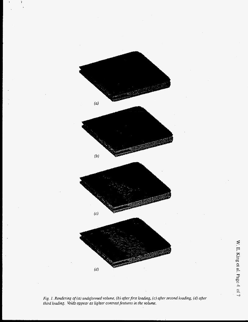
with an efficient, single-pass cluster labeling algorithim developed by Hoshen and Kopelman [ 101 and described in more detail elsewhere [ 1 13. All void contrasts, including those from ring artifacts, are displayed in Figure 1. Although it is possible to follow the growth of isolated voids, this was not done in this initial study.
RESULTS
As-DreDared sample
XTM revealed that the sample prepared in the 4-point bend geometry exhibited two dense interfaces between the aluminum and the sapphire. No resolvable voids were observed outside of three regions affected by ring defects. Figure l a shows a rendering of the volume studied with XTM. The profile of the notch was extracted from this data and was used as input for finite element calculations to calculate the stress state of the sample.
First deformation
Figure 2a shows the load-displacement curve for the first in a series of three deformations. Loading was relaxed at the first indication of the onset of plasticity. XTM revealed four resolv- able (size greater than 2 voxels) voids located at the interfaces between the metal and the sap- phire. These voids were of volume between 3 and 7 voxels. Three of the voids were lenticular in nature. The fourth, and largest, had an aspect ratio (ratio of the radius of gyration normal to the interface to that in the plane of the interface) of about I, i.e., the largest void was spherical. Figure l b show the rendered volume with voids (including those resulting from ring artifacts and those one voxel in size). Finite element modeling results for the maximum in triaxiality, maxi- mum in tensile traction at the interface, and their locations relative to the notch root are shown in Table I.
Table I. Finite element modeling results for the maximumin triaxiality, maximum in tensile stress at the interface, and their locations relative to the notch root relative to the foil thickness.
Loading %J 0 0 X d h 0 0 X,,lh
1 4.1 2.3 4.5 2.3
2 5.4 2.8 5.9 2.6
Yield stress used in this calculation was 12.2 MPa, foil thickness was 50 pn, and notch depth was 630 p.
Second deformation
Figure 2b shows the load-displacement curve for the second deformation. XTM revealed 53 resolvable voids located at the interfaces between the metal and the sapphire. Figure 3 shows a slice through the volume revealing several voids at the interfaces. A common feature of is that they are all at the interfaces and voids are never seen to nucleate on opposite sides of the foil directly across from each other; they are usually staggered with respect to each other. Voids of size less than -30 voxels are usually lenticular in shape. Between volumes of 30-100 voxels, the
c
1
Fig. 1. Rendering of (a) undeforrned volume, (b) aflerfirst loading, (c) after second loading, (d) after third loading. Voids appear as ligluer contrast features in the volume.

0 10 20 0 10 20 0 10 20 30 40 50 60
Displacement (pm)
Fig. 2. Load as afunction of cross-head displacement for (a)first loading, (b) second loading, (c) third loading.
aspect ratio grows to -0.6. For volumes in excess of 100 voxels, the aspect ratio decreases to -0.2. Figure IC shows a rendering of the void distribution and illustrates the increase in the void population compared with the first deformation.
Third deformation
Figure 2c shows the load-displacement curve for the third deformation. XTM revealed 13 1 resolvable voids located at the interfaces between the metal and the sapphire. While some small voids do take on a spheroidal shape, the general trend for the smallest and the largest voids is to have aspect ratios of <0.2. Voids in the range of 200-900 voxels in volume tend to have aspect ratios approaching 0.4. The void population has dramatically increased and the voids have spread ahead of the notch (Figure Id).
DISCUSSION
XTM has been used to elucidate the mechanism of ductile rupture of a 50 pn thick Al foil bonded between two sapphire cylinders subjected to Mode I loading. At the onset of plasticity, small lenticular voids form at each interface at a location consistent with the maxima in
Fig. 3. Slice through volume perpendicitlar to notch afer second deformation showing voids on both interfaces.

triaxiality and tensile traction at the interface. As such, this work reveals that debonding plays an important role in the failure at the earliest stages of plasticity. Previous observations of rupture in this system revealed the presence of voiding on the fracture surfaces, e.g. see Ref. 1 and 2. However, the authors were only able to link the origin of some voids with the interfaces, Le., the generalization of this observation to all voids was not clear. In this investigation, all voids were initially associated with an interface. Further, using conventional fractography, the mechanism of void nucleation and growth could not be revealed. The lenticular nature of these voids as revealed by XTM suggests that they may be formed by debonding and propagation of an interface crack rather than by nucleation and growth via dislocation agglomeration. The existence of debonds at interfaces in Al is consistent with observations in other systems, e.g., Au [3], Nb [4], and Cu [5], which debond but do not exhibit the extensive ductile dimpling found in AI. The observations of this work suggest that the tendency of a system to rupture in a ductile or brittle fashion may be controlled by the interplay of the interface bond strength and the yield strength of the metal. The formation of a void at an interface locally relaxes the constraint thus eliminating the possibility that a void will nucleate directly across the foil on the opposing interfice. This increases the constraint nearby giving rise to the tendency of the voids to be staggered with respect to each other.
As deformation proceeds, voids of intermediate size tend to become spherical under the influence of the triaxial stress state which serves to relieve the constraint locally. It is reasonable to conclude that the maximum in the constraint then shifts to locations farther in advance of the notch root where more small debonds form. At high strains, spherical voids continue to grow until they interpenetrate which eventually leads to the formation of the ductile ligaments ob- served in fractographs. There appears to be a second class of voids that remain lenticular throughout the deformation. These seem to be lenticular voids that have grown past some per- haps critical size above which the tendency to become spherical is diminished.
CONCLUSIONS
Ultrahigh vacuum diffusion bonding has been used to make model specimens in the AI/ sapphire system. The miocromechanics of failure for this system were observed by XTM. The primary findings are that (i) damage ahead of the notch initiates by interface debonding at a location coinciding with maxima in triaxiality and tensile traction at the interface, (ii) debonding occurs at the most early stages in the observation of plasticity, (iii) the debond expands for a limited distance, likely arresting due to crack tip blunting, (iv) this lenticular debond then be- comes spherical with further strain and (v) intergrowth of the spherical voids leads to the typical ductile rupture fracture surfaces observed in this system. Future efforts to model this effect will need to include the debonds at the interface which alter the state of stress.
ACKNOWLEDGEMENTS
The authors gratefully acknowledge Professor R. H. Dauskardt for providing the mechanical testing equipment used in this investigation. This work performed under the auspices of U. S. Department of Energy and the Lawrence Livermore National Laboratory under contract No. W-7405-Eng-48.

REFERENCES
1. 2.
3. 4. 5. 6. 7. 8. 9. 10. 11.
B. J. Dalgleish, K. P. Trumble, and A. G. Evans, Acta Metall. 37, 1923 (1989). W. E. King, G. H. Campbell, S. L. Stoner, and W. L. Wien, Cer. Eng. Sci. Proc., 15, 769 (1994). LE. Reimanis, B.J. Dalgleish, and A.G. Evans, Acta Metall. Mater. 39,3 133 (1991). I.E. Reimanis, Scripta Metall. Mater. 27, 1729 (1992). T.S. Oh, J. Rodel, R.M. Cannon, and R.O. Ritchie, Acta Metall. 36,2083 (1988). A. G. Varius, Z. Suo, and C. E Shih, J. Mech. Phys. Solids 39,963 (1991). V. Tvergaard and J. W. Hutchinson, Phil. Mag. A 70,641 (1994). W. E. King, et al., Mat. Res. SOC. Symp. Proc. 314,61 (1993). J. H. Kinney and M. C. Nichols, Ann. Rev. Mater. Sci. 22, 121 (1992). J. Hoshen and R. Kopelman, Phys. Rev. B,15 3438 (1976). J. H. Kinney, N. E. Lane, and D. L. Haupt, J. Bone and Miner. Res. 10,254 (1995).