Embed Size (px)
Citation preview
UC Berkeley Space Technologies and RocketryPost Launch Assessment Review
Project U.R.S.A.1
April 24, 2017
1Upright Recovery and Sight Acquisition
Contents
1 Flight Results1 Flight Results 21.1 Motor Used1.1 Motor Used . . . . . . . . . . . . . . . . . . . . . . . . . . . . . . . . . . . . . . . . 21.2 Altitude Reached1.2 Altitude Reached . . . . . . . . . . . . . . . . . . . . . . . . . . . . . . . . . . . . . 21.3 Vehicle Summary1.3 Vehicle Summary . . . . . . . . . . . . . . . . . . . . . . . . . . . . . . . . . . . . . 21.4 Data Analysis & Results of Vehicle1.4 Data Analysis & Results of Vehicle . . . . . . . . . . . . . . . . . . . . . . . . . . . 3
1.4.1 GPS Data1.4.1 GPS Data . . . . . . . . . . . . . . . . . . . . . . . . . . . . . . . . . . . . . 31.5 Payload Summary1.5 Payload Summary . . . . . . . . . . . . . . . . . . . . . . . . . . . . . . . . . . . . . 41.6 Data Analysis & Results of Payload1.6 Data Analysis & Results of Payload . . . . . . . . . . . . . . . . . . . . . . . . . . . 4
2 Payload Description2 Payload Description 5
3 Vehicle Dimensions3 Vehicle Dimensions 5
4 Scientific Value4 Scientific Value 5
5 Visual Data Observed5 Visual Data Observed 6
6 Lessons Learned6 Lessons Learned 66.1 Electronics6.1 Electronics . . . . . . . . . . . . . . . . . . . . . . . . . . . . . . . . . . . . . . . . . 66.2 Payload6.2 Payload . . . . . . . . . . . . . . . . . . . . . . . . . . . . . . . . . . . . . . . . . . 66.3 Recovery6.3 Recovery . . . . . . . . . . . . . . . . . . . . . . . . . . . . . . . . . . . . . . . . . . 76.4 Airframe6.4 Airframe . . . . . . . . . . . . . . . . . . . . . . . . . . . . . . . . . . . . . . . . . . 76.5 Safety6.5 Safety . . . . . . . . . . . . . . . . . . . . . . . . . . . . . . . . . . . . . . . . . . . 8
7 Competition Summary7 Competition Summary 87.1 Overall Experience7.1 Overall Experience . . . . . . . . . . . . . . . . . . . . . . . . . . . . . . . . . . . . 87.2 Educational Engagement7.2 Educational Engagement . . . . . . . . . . . . . . . . . . . . . . . . . . . . . . . . . 9
7.2.1 Summary of Events and Counts7.2.1 Summary of Events and Counts . . . . . . . . . . . . . . . . . . . . . . . . . 97.2.2 Closing Remarks7.2.2 Closing Remarks . . . . . . . . . . . . . . . . . . . . . . . . . . . . . . . . . 10
7.3 Budget7.3 Budget . . . . . . . . . . . . . . . . . . . . . . . . . . . . . . . . . . . . . . . . . . . 10
1
1 Flight Results
1.1 Motor Used
We used an Aerotech L1150 motor.
1.2 Altitude Reached
The altitude reached during our Huntsville flight was 4530 feet.
1.3 Vehicle Summary
The rocket was primarily constructed from Blue Tube. The fins were constructed from G10 fiberglassand were attached through the wall to the phenolic motor mount and connected to the booster outertube with carbon fiber and epoxy fillets. The nosecone was constructed from fiberglass, and thenosecone tip was replaced by a a vacuum formed clear PET-G tip for the target detection payloadexperiment.
The primary recovery system utilized a same-side dual-deployment mechanism initiated with two4-gram black powder charges between the Avionics Bay and Booster+ sections of the rocket. The24” elliptical drogue chute was deployed at apogee while the 72” toroidal main chute was deployed at1000 ft. AGL. Altitudes were determined with two altimeters: one Perfectflite Stratologger CF andone Missileworks RRC3. The dual deployment was made possible with two L2 Tender Descendersconnected series to ensure redundancy.
2
1.4 Data Analysis & Results of Vehicle
1.4.1 GPS Data
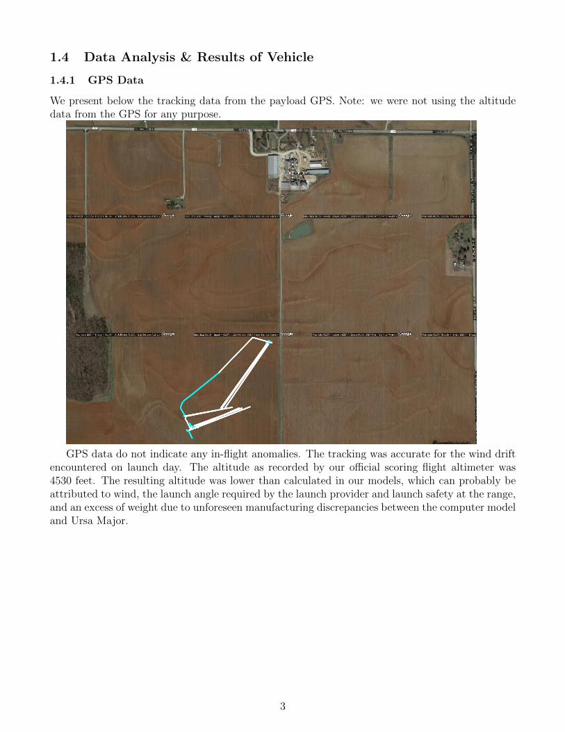
We present below the tracking data from the payload GPS. Note: we were not using the altitudedata from the GPS for any purpose.
GPS data do not indicate any in-flight anomalies. The tracking was accurate for the wind driftencountered on launch day. The altitude as recorded by our official scoring flight altimeter was4530 feet. The resulting altitude was lower than calculated in our models, which can probably beattributed to wind, the launch angle required by the launch provider and launch safety at the range,and an excess of weight due to unforeseen manufacturing discrepancies between the computer modeland Ursa Major.
3

1.5 Payload Summary
We attempted the target detection and upright landing payload challenge. During descent, acamera located inside the transparent nose cone tip would identify and track the ground targets.Our payload bay and nose cone were designed to then separate from the main body of the rocketentirely via a black powder charge, deploying a set of landing legs and parachutes with onboardservo motors and landing upright under the drag of those chutes.
At the time we first got our rocket onto the launch rail, around 11 am, electronics appeared tobe functioning perfectly. We did an on-rail test of the landing legs′ servo motors, which had beenknown to fail during previous tests, but there were no such issues and the motors worked flawlessly.However, we had to delay our launch due to a mechanical issue on the payload.
That problem took around two hours to fix; however, at that point, attempting to boot up theRaspberry Pi caused it to loop endlessly. A further two hours were spent attempting to fix theerror, including rewriting sections of the code and swapping our Raspberry Pi out for the backupwe had, but nothing seemed to work.
1.6 Data Analysis & Results of Payload
A major electronics failure prevented us from successfully launching our payload, but we gleanedmeaningful information from the failure. Our best guess at this point was that running multiplePython programs (target detection and upright landing) in parallel caused the Pi to crash on boot,although we remain unsure why this happened only about half the time.
The failure did serve to demonstrate the limitations of the Raspberry Pi a high-level computersystem with its own Linux-based OS, programmed mostly in Python, was not the right tool fora system in which robustness and speed are top priorities. Going forward, we intend to use anArduino, which is more minimalistic and therefore less prone to black box errors, as an interimsolution. As a long-term solution, we hope to transition to a custom ARM-based processor toprovide memory and processing power better than those achievable by an Arduino.
4
2 Payload Description
The objective of our vehicle’s payload experiment is to fulfill the Target Detection and UprightLanding challenge, which an onboard camera system identifies ground targets, and the sectionhousing the cameras lands upright. Our payload, SAGITTA-VL, uses an onboard camera mountedinside the nose cone viewing through a clear tip. A custom software package, operated using a Rasp-berry Pi camera, is used to view the ground during descent, and identify the three ground targetsby color. This sequence of operations constitutes “Target Detection”. After Target Detectionhas been completed, or after an altitude threshold has been reached, the payload section will beejected from the vehicle to be recovered independently. The payload deploys three parachutes viathe deployment of three landing legs. The positioning of the payload center of gravity below theparachutes causes the section to turn upright during its descent, allowing the payload to land up-right. This sequence of operations constitutes “Upright Landing”. The payload section consistsof an 18” section of tubing and a 21” nose cone. This acts as the upper section of the main vehicleairframe. A camera is mounted in the top of the nose cone, and views through a clear PETG tip.The tubing section contains three landing legs, which deploy out in order to assist Upright Landing.During ”launch configuration,” the legs are folded in so as to be flush against the airframe. During”landing configuration,” the legs are extended, and the inner assembly is exposed. The payloadparachutes are deployed via springs that push the parachutes out when they are exposed (i.e. whenthe legs are deployed). The legs are held in place using a latch 3d-printed into the landing leg,which are released by a servo motor that controls an arm with an attached roller bearing.
3 Vehicle Dimensions
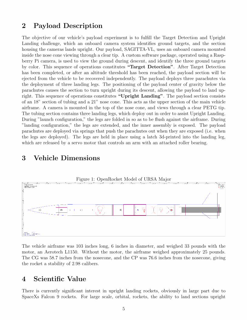
Figure 1: OpenRocket Model of URSA Major
The vehicle airframe was 103 inches long, 6 inches in diameter, and weighed 33 pounds with themotor, an Aerotech L1150. Without the motor, the airframe weighed approximately 25 pounds.The CG was 58.7 inches from the nosecone, and the CP was 76.6 inches from the nosecone, givingthe rocket a stability of 2.98 calibers.
4 Scientific Value
There is currently significant interest in upright landing rockets, obviously in large part due toSpaceXs Falcon 9 rockets. For large scale, orbital, rockets, the ability to land sections upright
5
allows for reusable sections, and large monetary savings. For rockets like those we flew this yearand hope to in the near future, upright landing sections allow for more controlled, gentle landings,and thus, the possibility of implementing designs that may otherwise be problematic and have thepotential for damage. Vision during flight, and the ability to track targets on the ground, holdssignificant value as well. For large scale rockets, this allows for the surveying of Earth, and otherastronomical bodies. The ability to both detect ground targets and land the detecting section of therocket leads to numerous possibilities for rockets of immediate interest to STAR. The next logicalprogression would be to land on targets, and following that, to locate ideal areas of the ground onwhich to land in flight.
5 Visual Data Observed
We observed slight weathercocking during the first second of flight, but there were no observableirregularities for the rest of flight. Upon recovery of the vehicle, we observed a small scorch markon the drogue parachute, but there was no structural damage to the chute or any other part of thevehicle.
6 Lessons Learned
6.1 Electronics
Failure mitigation and redundancy, with particular regard to the electronics component of our pay-load, has proved to be a design consideration that we will need to improve upon on future missions.Having our upright landing legs controlled by the same computer that performed target detec-tion prevent us from attempting either experiment whenever that computer failed. Additionally,electrostatic discharge analysis of the materials surrounding our electronic components as well asmitigative measures (like a case around our Raspberry Pi) should be conducted in future projects.
6.2 Payload
With regards to manufacturing, we discovered that reducing the number of hand-measured cutsand joins during our manufacturing processes and increasing the amount of parts manufactured bycomputer-controlled processes (like 3D-printing and laser cutting) drastically improves the aero-dynamic profile of the payload without many added build-hours. In fact, after iterating on the3D-printed parts, we managed to also improve the structural integrity of the payload by improv-ing tolerancing and adding material in places that we noted experienced large stresses during ourunexpected launch failure prior to FRR.
Throughout the design and build process, scheduling was a persistent issue. The prototypingstage needs begin as soon as possible to allow for a fully flushed out design. Many of the design issuesthat ultimately pushed payload to be behind schedule were discovered during the build process—particularly surrounding tolerancing and hand-manufacturing, in addition to forces exerted on partsthat were not accounted for, often resulting in surface-to-surface binding/friction issues. Theseissues could have been avoided if more time had been dedicated to prototyping different designs.Then, more time should always be alloted for the build process so that issues can be properly dealtwith as they arise. This includes participating in early launches so that any external problems suchas weather don’t delay the schedule.
6
6.3 Recovery
When reviewing the recovery system right before launch, many details should be looked over, andwith an appropriate checklist the system can be made as robust and consistent as possible. Thereis a necessity to constantly update the checklist in order to foolproof the system against all theissues that can be thought of. Oversights such as shock cord tangling or wires failing to break apartlead to solutions like shock cord arrangement and wire disconnects being added to the checklist,effectively preventing the issue from future launches. The checklist allowed for a 100% success rateregarding the recovery system in all flights.
In terms of the avionics bay itself, several important lessons were learned. First, a more robustdesign is needed for the switches that activate the altimeters. The switches experienced a higher rateof failure after prolonged use. The door on the avionics bay made preparation before flight extremelyefficient, as well as allowed for easy access to all electronics needed for successful deployment.However, the door limited the minimum size that the avionics bay could be and increased drag.Counterboring the holes for the screws used to hold down the door did prevent the increase in dragfrom becoming too large. Future designs would consider a more compact arrangement that stillallows for easy access before flight, as the current avionics bay had a large amount of wasted space.The 3D printed sled used to hold the altimeters worked extremely well, and allowed for betterorganization within the avionics bay. A more reliable way to maintain alignment is also important,as shear pin holes had to be re-drilled several times. Alternatives to shear pins will be consideredin future designs.
One of the most surprising lessons learned was the reliability and consistency of the dual-deployment system, which utilized a unique orientation of two L2 Tender Descenders attachedin series. The design was fabricated in a fashion that would ensure main chute deployment afterdrogue deployment if any, or both, of the two Tender Descenders were ignited. This led to extremelysuccessful recoveries in every launch, except for the Full Scale re-flight, where the trajectory of therocket was severely impaired with the launch rail. In the end, the decision to choose this methodof employing Tender Descenders in the deployment system over other deployment systems, such asJolly Logic, provided a creative, redundant, and most importantly, safe method of recovering therocket. In the future, it can be possible to manufacture the Tender Descender components in house,allowing for more control and ownership in the design and implementation process.
In the future, more effort can be made in creating a more durable and robust method of pro-tecting the main and drogue parachutes. In the final full-scale launch, the drogue chute was slightlycharred, which was most likely due to the lack of complete protection during the black powder ejec-tion charge ignition. This lack of protection could have been a result of having the rocket jostledaround during transportation of the rocket from the prep station to the field. As a result, designinga more sturdy and reliable parachute bag/compartment would prevent future impairments to theparachutes.
6.4 Airframe
The summation of smaller issues can have a big effect on the rocket as a whole. Our altitude suffereddue to inconsistencies in the airframe as well as sub-standard attention to detail in regards to thefinish of the rocket.
Also, it is imperative that the execution of putting pieces together be as close to the intendeddesign as possible. For example, when attaching the fins to the airframe during the subscale, theywere not exactly 120◦ apart which caused unintended roll. For the fullscale, a fin jig was used toensure that they were spaced as close to 120◦ as possible.
7
In addition to taking into account proper construction, it is vital that proper weight estimationsare made. Without proper weight estimations, the team cannot come up with a design that satisfiesthe altitude requirement. After the build process, the rocket was 3 lbs. heavier. This makeshundreds of ft. of difference in altitude.
There were also some logistical parts throughout this year that caused some issues. The mostprevalent was the rush shipping orders that had to be made consistently. Due to a naive designschedule, many parts were being ordered a couple days before they were needed. Unfortunately,model rocketry companies are very slow if ordered with regular shipping. This led to a constantneed for extra money for rush shipping. For airframe, rush shipping was 1
3of the total cost. This
is unacceptable and needs to be something that is improved as the club goes forward.Finally, the build process documentation needs to be better. When something breaks, it is
critical that the piece be replaced with specifications as close to the original as possible. Thisprocess can be streamlined through the use of proper documentation of how each part was built.Going forward, this process needs to be implemented with full detail so that anyone can take overand build the piece if it is necessary.
6.5 Safety
The most significant safety problem this year was the repeated obsolescence of various parts of thechecklists at each launch. Due to different mechanical and electrical problems at launches, therewas a significant amount of on-site construction, which immediately makes the relevant checklistsections out-of-date and useless. Next year we therefore should have more troubleshooting steps inour checklists, which ideally will obviate some amount of this launch-day rocket improvement: ifsome item does not work as intended, troubleshooting may fix the issue, and make one-off repairsunnecessary.
There were not other significant safety issues, and as such we will focus primarily on producingmore accurate and detailed checklists next year.
7 Competition Summary
7.1 Overall Experience
This was not only STARs first year competing in the NASA Student Launch Competition, butits first year competing in any competition and designing a rocket. Along the way we faced amultitude of challenges and obstacles. STAR consists largely of members who, at the beginningof this competition, had no experience designing, manufacturing, constructing, or flying a rocket.The design challenge we took part in this year of landing the upper part of the rocket, led to muchscientific value for the team and team members. In order to design and build our payload, we notonly had to consider the mechanical and electrical components, but also, how to ensure no lossof safety, how to mitigate the hindrance to the aerodynamics of the vehicle, the optimal sequenceof target identification, leg deployment, and ejection. This was not simply an engineering designchallenge, but blank challenge. As a result, the value from the process extended much past theknowledge in rocket design and construction which we engaged in.
The sub-scale flight took place on December 3rd, and was the first high powered launch manyteam members had experienced. The payload was only simulated with sand ballast for this flight.The sub-scale flight and recovery was a complete success. Following winter break, manufacturingand construction of the full scale rocket began. The full scale flight was initially planned for February
8
4th. However, due to rain cancelations and payload design modifications, our first full scale flightdid not take place until March 4th. While launch and recovery was sucessful, the payload, due toelectrical issues discussed in length in previous reports, was not tested. At a March 15th launchwith the goal of testing payload, a launch rail failure caused or rocket to crash and become severlydamaged. This was the point were STAR faced its largest challenge. In order to be able to launchour rocket in Huntsville, we had 13 days to rebuild large portions of our rocket and relaunch itsucessfully. After much hard work and design modifications, not to mention a long drive to MojaveDesert to launch, the final test launch was sucessful.
18 team members were able to travel to Huntsville and take part in launch week activities.The experiences there were extremely valuable and provided team members with many ideas andasperations for things to explore in the following year.
7.2 Educational Engagement
7.2.1 Summary of Events and Counts
Habitat for Humanity Campus Visit
• Date: November 19, 2016
• Location: UC Berkeley Campus
• Total Count: 62
• Description: Local elementary schools visited campus. We held multiple demonstrations andpresentations of bottle rockets and how rockets work in general.
Calapalooza
• Date: January 26, 2017
• Location: UC Berkeley Campus
• Total Count: 71
• Description: A Berkeley-wide event where clubs and programs show off their activities to newstudents.
Arcadia High School Visit
• Date: November 28, 2016
• Location: Arcadia High School
• Total Count: 30
• Description: A team member visited his high school and gave a talk on rocketry, Nasa StudentLaunch, and held a small rocket demonstration.
Engineering 4 Kids
• Date: March 11, 2017
9
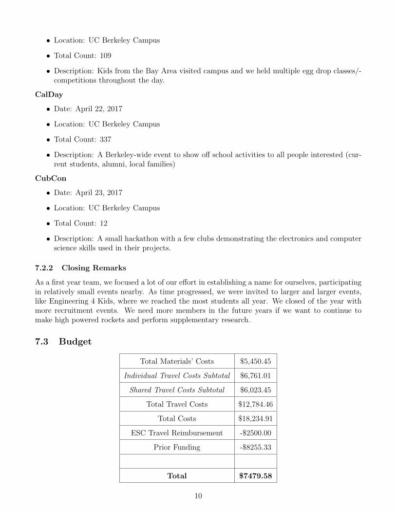
• Location: UC Berkeley Campus
• Total Count: 109
• Description: Kids from the Bay Area visited campus and we held multiple egg drop classes/-competitions throughout the day.
CalDay
• Date: April 22, 2017
• Location: UC Berkeley Campus
• Total Count: 337
• Description: A Berkeley-wide event to show off school activities to all people interested (cur-rent students, alumni, local families)
CubCon
• Date: April 23, 2017
• Location: UC Berkeley Campus
• Total Count: 12
• Description: A small hackathon with a few clubs demonstrating the electronics and computerscience skills used in their projects.
7.2.2 Closing Remarks
As a first year team, we focused a lot of our effort in establishing a name for ourselves, participatingin relatively small events nearby. As time progressed, we were invited to larger and larger events,like Engineering 4 Kids, where we reached the most students all year. We closed of the year withmore recruitment events. We need more members in the future years if we want to continue tomake high powered rockets and perform supplementary research.
7.3 Budget
Total Materials’ Costs $5,450.45
Individual Travel Costs Subtotal $6,761.01
Shared Travel Costs Subtotal $6,023.45
Total Travel Costs $12,784.46
Total Costs $18,234.91
ESC Travel Reimbursement -$2500.00
Prior Funding -$8255.33
Total $7479.58
10

A crowd funding campaign is currently underway for with the goal of $5000 dollars to furtherreimburse members for travel costs and for next year. More funding opportunities are also underwayas we hope to explore a much wider range of projects next year.
11