Embed Size (px)
DESCRIPTION
This addresses topics concerning the development offuture Unmanned Aerial Vehicles (UAV) so they canoperate safely within the community of the FederalAviation Administration (FAA) and the InternationalCivil Aviation Organization (ICAO).
Citation preview
UAVs in Civil Airspace:Safety Requirements
Robert Loh, Yi Bian & Tim RoeInnovative Solutions International
ABSTRACT
This addresses topics concerning the development offuture Unmanned Aerial Vehicles (UAV) so they canoperate safely within the community of the FederalAviation Administration (FAA) and the InternationalCivil Aviation Organization (ICAO). Studies by theDefense Science Board, the Office of Science andTechnology, Government Accountability Office, and theCongressional Research Service Library of Congress haveall emphasized that soon there will be a significantnumber of UAVs operating side-by-side with mannedcivil aircraft in the FAA's National Airspace System(NAS). It is anticipated that future UAVs will performmany of the dull, dirty, and dangerous civilian missions.In 2006, about 600 UAVs were manufactured in the USalone. Therefore, there is an urgent need for developers ofUAVs to understand safety certification for operations inthe NAS, and that safety certification starts with safetyrequirements, safety design, safe development processes,safety verification, and safe operating procedures in theplanned operational environment.
BACKGROUND
We present and discuss the experiences and lessons gainedby these authors on the development of end-to-end aviationsafety; from safety requirements to the final safetycertification in the planned operational environment. Theauthors' previous and ongoing works include the GlobalNavigation Satellite Systems (GNSS) systems such as GPS,WAAS, LAAS, MSAS, GPS III, and different operationalenvironments at different airports such as IncheonInternational Airport. The FAA started with two traditional
Author's Current Addresses:R. Loh, Y. Bian and T. Roe, Innovative Solutions International, 1608 Spring Hill Road,Vienna, VA 22182, USA.
Based on a presentation at a PLANS Conferrence.
0885/8985/09/ S25.00 USA 2009 IEEE
IEEE A&E SYSTEMS MAGAZINE, JANUARY 2009
safety certifications processes: airborne system certification,and ground system certification, governed mostly by FederalAviation Regulations (FAR) and FAA's AcquisitionManagement System (AMS), respectively. However, whenFAA implemented GNSS, the lines between airborne andground systems blurred, and, as a result, many currentCommunications, Navigation, Surveillance, and Air TrafficManagement (CNSIATM) systems have to follow bothprocesses. We also discuss the current Safety ManagementSystems being developed by both FAA and ICAO as anintegrated, systematic, and harmonized approach and processto sort out differing safety requirements from FAA,SAB-ARP, MIL-STD, RTCA, ASTM, ICAO, etc., to providethe eventual safe operations within NAS. The discussion willthen focus on the real world of institutional, operational, andtechnical issues for safety certification worldwide. Despitethe numerous standards and guidance documents, many pastsafety analyses and studies were guided by best practices thatwere used successfully in the past to streamldine the processof providing all of the required documentations andverifications. One such area is in the use of the "IntegrityPanel of Experts" that was used successful in theimplementation of safety for the FAA's Wide AreaAugmentation System (WAAS) and Local AreaAugmentation System (LAAS) programs. In many areas ofthe world, safety certification, from a technical point of view,is only the first step to achieving safety certification to fly intheir national and sovereign airspace. Finally, we show thefirst steps that UAV manufacturers need to consider if theywant their UAVs approved to fly safely in different nationalcivilian airspace.
INTRODUCTION
The prestigious Defense Science Board of the USDepartment of Defense performed a study in 2004 thatrecommended: "Unmanned Aerial Vehicle (UA V) andUninhabited Combat Aerial Vehicle (UCA V) become anintegral part of the US force structure, and not an additionalasset, " and that " UA V and UCA V be allowed unencumberedaccess to the US National Airspace System (NAS) outside ofrestricted areas here in the US and around the world."
5
A Common L
- Federal Aviation Regulaions:e.g. FAR 26.1309
Advisory Circulars:e.g. AC 26.1309
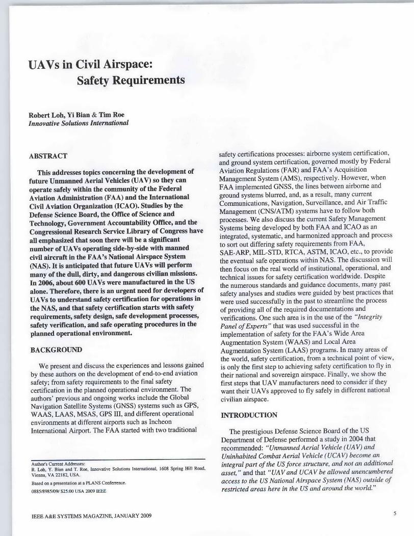
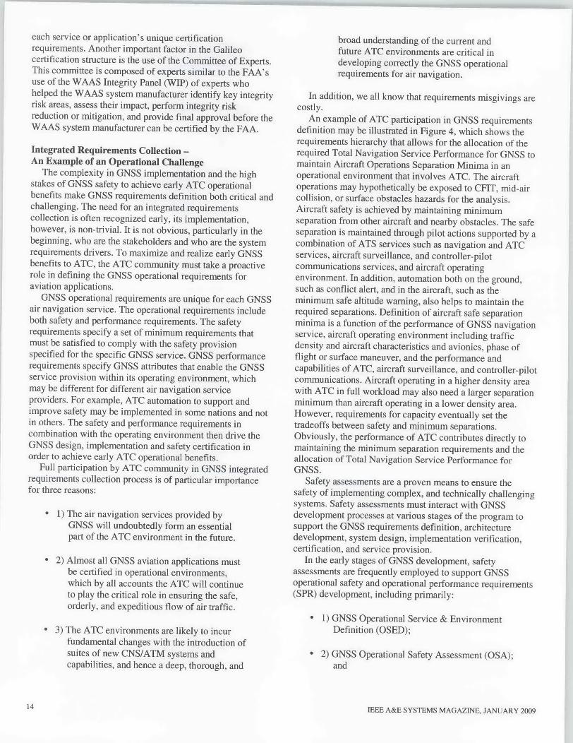
Fig. 1. FAA Two- and Three-Party Systems
However, the same report showed that the best UAV accidentrate is about 32 per 100,000 flight hours versus 1 per 100,000flight hours for small general aviation aircraft and about 0.01per 100,000 flight hours for large airliners. That means thebest UAV accident rate is about 3,200 times more often thanlarge airliners, even though the number of UAV operationalhours are much less than 100,000 hours, and historically, theaccident rate has decreased as the number of hours ofoperations have increased. Numerous studies have beenperformed by the GAO with regard to UAV, and they havealso recommended that " UA Vbecome fully interoperablewith other UA V, with manned aircraft systems, and even withconventional forces. " The Congressional Research Service ofthe Library of Congress have also reported that Congressneed to consider the "-. ..unanticipatedflexibility andcapability of UA V has led some analysts to suggest thatmore, ifnot most, of the missions currently undertaken bymanned aircraft could be turned over to unmanned aerialplafforms, and that manned and unmanned aircraft couldoperate together. " Finally, in a briefing by the Office ofScience and Technology Policy of the Executive Office ofthe President of the United States, it stated that "We mustface the likelihood that UA V are soon coming to the NAS insignificant numbers and that we must address UA Vintegration into our ground and airspace considerationsASAP. "
At the same time that UAVs are being designed to flysafely in the NAS, the NAS itself is changing as the conceptof a satellite-based global Communications, Navigation, andSurveillance/Air Traffic Management (CNS/ATM)infrastructure for civil aviation worldwide is beingintroduced. The implementation of this new CNS/ATMsystem raises a multitude of institutional, operational, andtechnical barriers and challenges that must be overcome
before the full benefits of the new CNS/ATM infrastructurecan be realized. A key challenge to this implementation is thesafety of satellite-based CNS/ATM systems. On the leadingedge of this satellite-based CNS/ATM systemimplementation is the navigation element called the GlobalNavigation Satellite System (GNSS), such as the USprovided Global Positioning System (GPS). Ensuring GNSSsafety for civil aviation has proved significantly moredemanding than provision for any single piece of traditionalground-based equipment. The GNSS projects include thecertification and use of the GPS, Wide Area AugmentationSystem (WAAS); Local Area Augmentation System(LAAS); and the US Department of Defense (DoD) GPSmodernization program called the GPS III. Manystakeholders are involved in the safety certification of GNSS,and they represent almost all elements of NAS stakeholdersincluding: the FAA, airlines, safety regulators, certificationauthorities, air-traffic controllers, pilots, airspace planners,flight procedure designers, flight rule-making authorities,equipment manufacturers, system designers, and CNS/ATMservices' providers and operators. Most of those challengesfor GNSS are now being met, however, for UAVs there willbe new challenges. For UAVs to safely operate in the NAS,all aspects of their internal CNS/ATM-related systems mustbe evaluated in the context of the existing civil aviationCNS/ATM operations and maintenance, and in conjunctionwith all the other aviation and user stakeholders.
This topic is concerned with safety requirements forUAVs, but we must start with GNSS safety requirementsdevelopment. These authors summarize and discuss theirobservations and experiences in working on GPS, WAAS,LAAS, MSAS, and GPS III programs, hoping that usefulrecommendations can be drawn from these experiences forfuture UAV certification to fly in the NAS. It is these
6 IEEE A&E SYSTEMS MAGAZINE, JANUARY 2009
lkPrinciple
Respective Requirements Guidelines
6
FAA Order:e.g. FAA Order 8040A4 SRM
-Acquisition Management System:eag. AMS 2.9.13
*Comparative Safety Assessment (CSA)
OPreliminary Hazard Analysis (PHA)
*Safety Requirements Verification Table(SRVT)
*Software Safety
*Safety Asses t resuIts
'A rov=P o Investment Analysis
*Hazard Tracking and AccidentInvestigation System I N T EGRAT &R 0D U CT-Track Medium and High Risks M-Closed loop Risk Acceptance-Capture and analyze incidents --Identify' high risk trends forfarither detailed investigation 3= = = Safety Assessment Report (SSAR)
O0perating and support Hazard Analysis(O&SHA)-operations HazardsFocus on Human Error/Human Factors-Consider Maintenance and Support Hazards
*Hazard Tracking and Risk Resolution
OSofiware Safety
Operational Safety Assessment (OSA)-Operational Environment Description (OED)-Operational Hazard Assessment (ORA),equivalent to Functional Hazard Assessment(FHA) including Software contributions-Allocation of safety objectives andrequirements (ASOR), SW Req. Analysis
*Safety Assessment results (RAC)____
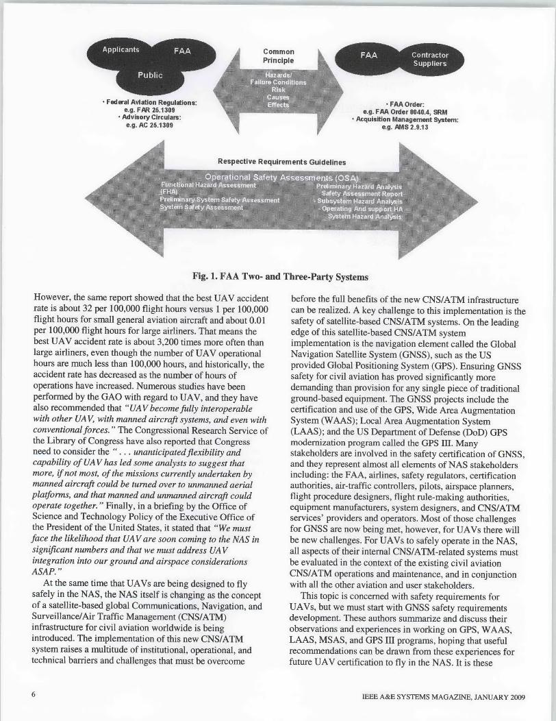
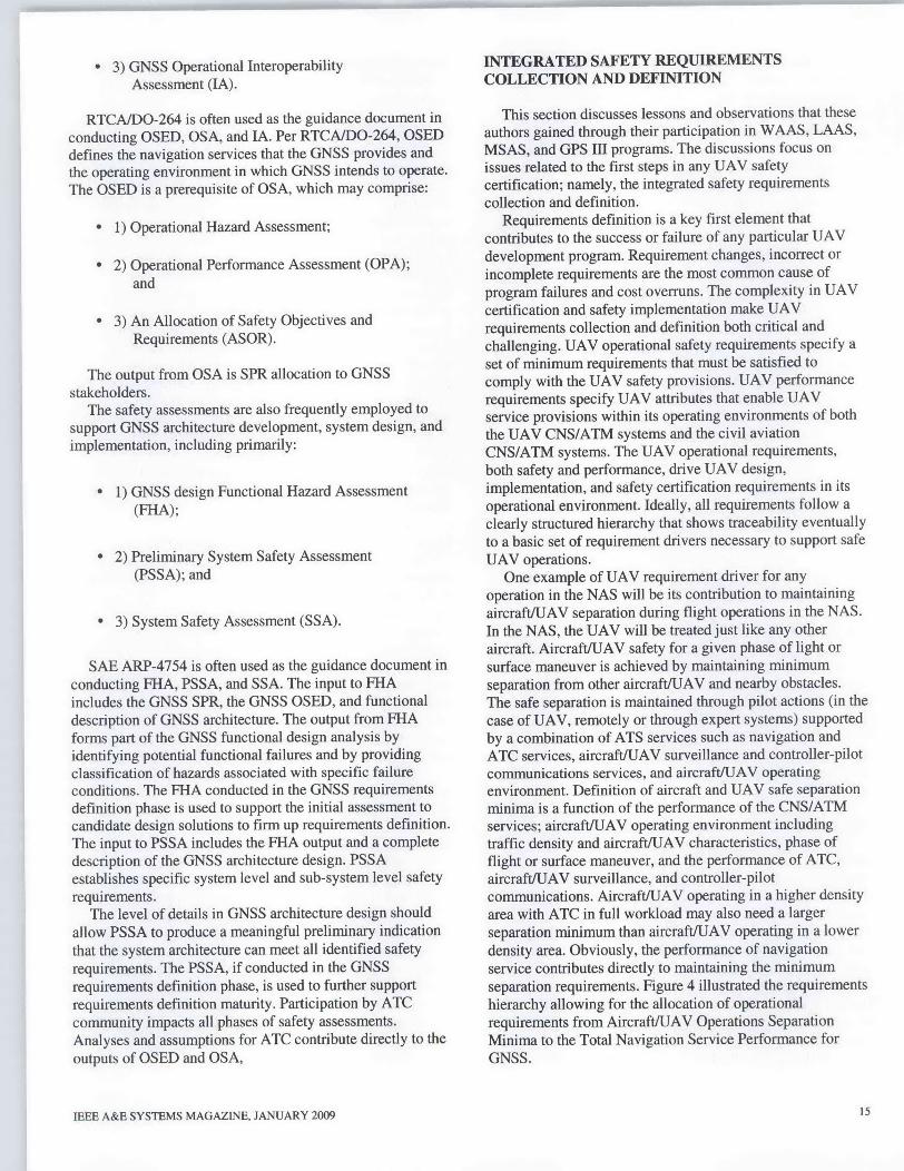
Fig. 2. FAA's AMS and Safety-Related Milestones
authors' view that the lessons learned apply in general to the
development and certification of any CNSIATM capabilitiesand services for NAS, and they are particularly applicable tothe development of safety certification of new CNS/ATMsystems, such as those to be used by UAVs in the NAS.
FAA SAFETY CERTIFICATION
The safety certification services provided by FAA have
traditionally been divided along the line of airborne systemcertification and ground system certification. The FAAaircraft certification organization operates a three-partysafety system. The FAA system acquisition and researchorganization operates a two-party safety system. The basis of
aircraft and airborne system certification in the three-partyprocess is governed by US public law documented in theFederal Aviation Regulations (FAR) and FAA AdvisoryCirculars (AC) such as FAR 25.1309 and AC 25.1309. Thethree-party process includes:
* 1) the applicant seeking certification,
* 2) the public who will use the certified systemor service, and
* 3) the FAA as the certification authority.
IEEE A&E SYSTEMS MAGAZINE, JANUARY 2009
The basis of ground system certification in the two-partyprocess is governed by FAA Orders and the FAA's LifecycleAcquisition Management System (AMS) policy. Only twoparties are involved:
* 1) the contractor who supplies, develops, orprovides the system or service, and
* 2) the FAA who acquires, uses, and certifiesthe system or service.
Figure 1 illustrates the differences and similarities with the
FAA two-party and three-party certification systems. We
note that both the two-party and three-party systems usefundamentally the same engineering methodologies and
principles. They are largely equivalent when usedappropriately with care in ensuring system safety. Bothsystems require substantiation on:
* 1) the identification of hazards/failure
conditions, causes, and effects,
* 2) assessment of risk, and
* 3) validation and verification of safetyrequirements.
7
*LAAS SOW includingCDRLs and DIDs (ARP4754/4761):
*SAO1 Safety Plan
#SA-02 EHA/OHA
OSA-06 KRA Reports,o-Subsystem Hazard Analysis
(SSHA)
*Software Safety
S-Consider COTSiNDI-Descriptive Criticality ofsystem and softwarefunctionality in the NAS
*Ensure SSPP (incl. SwSPP) iscaptured in LAAS AcquisitionProgram Baseline
*System Hazard Analysis(SHA)-Consider Operating andAmbient Environment
.0Consider Interfaces-Performed at NAS SystemLevel
*Software Safety
However, the two systems have different emphasis andthey describe their respective processes with subtly differentterminologies. In practice, the two-party systems considersbroader aspects of program integration such as cost andschedule, while the three-party systems are more strictlyfocused on safety with explicit disregard for system cost andschedule. The development of GNSS and other futureCNS/ATM systems have blurred the lines between aircraftand ground systems. The highly integrated GNSS systemsrequire a conjunction between the system development roleand the aircraft/operation certification role. For example, thecertification of WAAS in the United States have combinedthe practices of the two-party and three-party systems withparticipation by both the airborne and ground certificationauthorities.
FAA lifecycle Acquisition Management System (AMS)process is built around a logical sequence of AMS phases anddecision points as illustrated in Figure 2. AMS application isflexible and may be tailored by the FAA AcquisitionExecutive or Joint Resources Council (JRC) for differentcircumstances and needs. The trigger point of GNSSprograms such as WAAS, LAAS, and FAA support to DoD'sGPS modernization program is driven by both the needs ofevolving NAS and the availability of new CNS/ATMtechnologies. The AMS process includes four phases:
* 1) Mission Analysis;
9 2) Investment Analysis;
* 3) Solution Implementation; and
0 4) In-Service Management.
The Mission Analysis establishes the basis for long-rangestrategic planning by individual service organizations and theFAA as a whole. Research projects often support and provideinformation to mission analysis. The Investment Analysis isconducted to ensure FAs critical needs are satisfied bypractical and affordable solutions and evaluates alternativesolutions to mission need and provides realistic options to theJRC to achieve best overall value for the FAA and itscustomers. The Solution Implementation begins at the finalinvestment decision when the JRC approves and funds aninvestment program and authorizes the service organizationto proceed with implementation. Solution implementationends when a new service or capability is commissioned intooperational use at all sites. The In-Service Decisionauthorizes deployment of a solution into the operationalenvironment. This decision establishes the foundation foroperational readiness to be declared at key site andsubsequent sites following completion of joint acceptanceand inspection by the operating service organization andcertification of compliance with security and safetyrequirements. It also entails periodic monitoring and
evaluation of fielded products and services, and feedback ofperformance data into mission and investment analysis as thebasis for revalidating the need to sustain deployed assts ortaking other action to improve service delivery.
The FAA Safety Management System (SMS) is the resultof a US commitment to meeting ICAO air traffic service(ATS) safety requirements per ICAO Annex 11, ICAO-ATMDocument 4444, and the ICAO SMS Manual. The FAAstrategy to complete SMS implementation is to leverageexisting safety processes and best practices and to organizethem into a consistent framework of systematic andintegrated method for managing ATC and navigationservices, while at the same time to ensure that it is alignedwith the ICAO SMS Manual. The FAA SMS requires allorganizations that have a role in air traffic service provision,including those external to the Air Traffic Organization(ATO), to identify and mitigate safety risk. The SMSfacilitates uniform and consistent documentationrequirements such as safety risk management documents(SRMD), safety incident reports, and safety inspection andevaluation reports that provide risk management decisionmakers with needed information regarding safety hazards andrisks associated with system (hardware and software),procedures, and airspace designs.
The SRM is a fundamental component of the FAA AMSprocess and FAA SMS - it ensures that all safety-relatedchanges are documented and resolved, whether the change isto a componlent, a system, or the NAS itself. The purpose ofSRM is to identify, evaluate, and eliminate or control systemhazards during the lifecycle of a given program or system.The primary policy document governing SRM objectives isFAA Order 8040.4, which sets requirements for theimplementation of safety risk management within the FAA.The order permits quantitative or qualitative assessments butrequires all assessments to be scientifically objective,unbiased, and inclusive of Al relevant data, to the maximumextent feasible. Assumptions are required to be avoided whenfeasible. Unavoidable assumption must be conservative andclearly documented with a sound basis of rationale. For eachprogram subject to safety risk management, while themethods and documentation requirements can be tailored, aset of safety risk management criteria must be satisfied thatinclude requirements for risk management planning, hazardidentification, risk analysis by severity, and likelihood ofoccurrence, risk assessment against pre-determinedacceptability criteria, and risk management-based decisions.
A systematic SRM process involves five general steps:
0 1) system description;
0 2) hazards identification;
9 3) risk analysis;
* 4) risk assessment; and
e 5) risk control.
IEEE A&E SYSTEMS MAGAZINE, JANUARY 2009
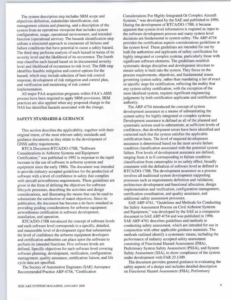
The system description step includes SRM scope andobjectives definition, stakeholder identification, riskmanagement criteria and planning, and a description of thesystem from an operations viewpoint that includes systemconfiguration, usage, operational environment, and intendedfunction (operational service). The hazards identification steputilizes a structured approach to enumerate all failures andfailure conditions that have potential to cause a safety hazard.The third step performs analysis of each hazard in terms of itsseverity level and the likelihood of its occurrence. The fourthstep classifies each hazard based on its documented severitylevel and likelihood of occurrence to risk level. The fifth stepidentifies feasible mitigation and control options for thehazard, which may include selection of best risk controlresponse, development of risk mitigation and control plan,and verification and monitoring of risk controlimplementation.
All major FAA acquisition programs within FAA's AMSprocess have been required to apply SRM provisions, SRMpractices are also applied when any proposed change to theNAS has identified hazards associated with the change.
SAFETY STANDARDS & GUIDANCE
This section describes the applicability, together with theiroriginal intent, of the most relevant safety standards andguidance documents as they relate to the development ofGNSS safety requirements.
RTCA Document RTCAIDO- 17813, "SoftwareConsiderations in Airborne Systems and EquipmentCertification," was published in 1992 in response to the rapidincrease in the use of software in airborne systems andequipment since the early 1980s. The document was intendedto provide industry-accepted guidelines for the production ofsoftware with a level of confidence in safety that complieswith aircraft airworthiness requirements. These guidelines aregiven in the form of defining the objectives for softwarelifecycle processes, describing the activities and designconsiderations, and illustrating the means that can be used tosubstantiate the satisfaction of stated objectives. Since itspublication, the document has become a de-facto standard inproviding guiding considerations for airborne equipmentairworthiness certification in software development,installation, and operation.
RTCAIDO-178B introduced the concept of software levelsand each software level corresponds to a specific, detailed,and measurable level of development rigor that substantiatethe level of confidence the airborne equipment developersand certification authorities can place upon the software toperform its intended functions. Five software levels aredefined. Specific objectives for each software level coveringsoftware planning, development, verification, configurationmanagement, quality assurance, certification liaison, and lifecycle data are specified.
The Society of Automotive Engineers (SAE) AerospaceRecommended Practice ARP-4754, "Certification
IEEE A&E SYSTEMS MAGAZINE, JANUARY 2009
Considerations For Highly-Integrated Or Complex AircraftSystems," was developed by the SAE and published in 1996.During the development of RTCAIDO- 1 7813, it becameapparent that system level information is required as input tothe software development process and many system leveldecisions are fundamental to system safety. The ARP-4754provides the certification aspects considerations guidelines atthe system level. These guidelines are intended for use byboth the authorities and applicants of safety certification forhighly integrated or complex systems, particularly those withsignificant software elements. The guidelines establishsystematic design discipline and development structure toensure safety is built into the system. They focus on theprocess requirements, objectives, and fundamental issuesgoverning system safety, rather than mandating a list of exactor specific steps for certification, reflecting the reality thatany system safety certification, with the exception of themost idealized system, requires significant engineeringjudgments by both certification applicants and certificationauthority.
The ARP-4754 introduced the concept of systemdevelopment assurance as a means of substantiating thesystem safety for highly integrated or complex systems.Development assurance is defined as all of the planned andsystematic actions used to substantiate, at sufficient levels ofconfidence, that development errors have been identified andcorrected such that the system satisfies the applicablecertification basis. The level of required developmentassurance is determined based on the most severe failurecondition classification associated with the potential systemfailure. Five levels of development assurance are defined,ranging from A to E corresponding to failure conditionclassification from catastrophic to no safety effect, broadlyconsistent with the definition of software level as defined inRTCAIDO- 178B. The development assurance as a processinvolves all traditional system development supportingprocesses such as requirements definition and validation,architecture development and functional allocation, designimplementation and verification, configuration management,certification coordination, and quality assurance, andadditional safety assessment processes.
SAE ARP-4761, "Guidelines and Methods for Conductingthe Safety Assessment Process on Civil Airborne Systemsand Equipment," was developed by the SAE as a companiondocument to SAE ARP-4754 and was published in 1996.SAE ARP-4761 describes guidelines and methods toconducting safety assessment, which are intended for use inconjunction with other applicable guidance materials. Themethods outlined identify a systematic means, including theperformance of industry accepted safety assessmentconsisting of Functional Hazard Assessment (FHA),Preliminary System Safety Assessment (PSSA), and SystemSafety Assessment (SSA), to show compliance of the systemunder development with FAR 25.1309.
The document provides general guidance in evaluating thesafety aspects of a design and includes detailed descriptionon Functional Hazard Assessment (FHA), Preliminary
9
System Safety Assessment (PSSA), System SafetyAssessment (SSA), Fault Tree Analysis (FTA), DependenceDiagram (DD), Markov analysis (MA), Failure Modes andEffects Analysis (FMEA), Failure Modes and EffectsSummary (FMES), Zonal Safety Analysis (ZSA), ParticularRisks Analysis (PRA) and Common Modes Analysis (CMA).
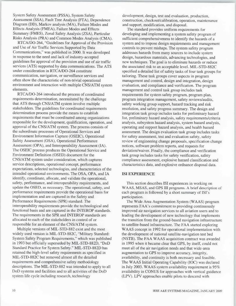
RTCAIDO-264, "Guidelines for Approval of the Provisionand Use of Air Traffic Services Supported by DataCommunications," was published in 2000. It was developedin response to the need and lack of industry-acceptedguidelines for approval of the provision and use of air trafficservices (ATS) supported by data communications. The ATSunder consideration in RTCAIDO-264 constitutecommunication, navigation, or surveillance services andoften show the characteristic of non-trivial operationalenvironment and interaction with multiple CNS/ATM systemelements.
RTCAIDO-264 introduced the process of coordinatedrequirements determination, necessitated by the challengethat ATS through CNS/ATM system involve multiplestakeholders. The guidelines for coordinated requirementsdetermination process provide the means to establishrequirements that must be coordinated among organizationsresponsible for the development, qualification, operation, andapproval of the CNS/ATM system. The process consists ofthe subordinate processes of Operational Services andEnvironment Information Capture (OSEIC), OperationalSafety Assessment (OSA), Operational PerformanceAssessment (OPA), and Interoperability Assessment (IA).The OSEIC process produces the Operational Service andEnvironment Definition (OSED) document for theCNS/ATM system under consideration, which capturesservice descriptions, operational concept, performanceexpectations, selected technologies, and characteristics of theintended operational environments. The OSA, OPA, and IAidentify, coordinate, allocate, and validate the operational,safety, performance, and interoperability requirements, andupdate the OSED, as necessary. The operational, safety, andperformance requirements provide the operational basis forimplementation and are captured in the Safety andPerformance Requirements (SPR) standard. Theinteroperability requirements provide the technological andfunctional basis and are captured in the INTEROP standards.The requirements in the SPR and INTEROP standards areallocated to each of the stakeholders in control of orresponsible for an element of the CNS/ATM system.
Multiple versions of MIL-STD-882 exist and the mostwidely used version is MIL-STD-882C, "Military Standard:System Safety Program Requirements," which was publishedin 1993 but officially superseded by MIL-STD-882D, "DoDStandard Practice for System Safety." MIL-STD)-882D hasretained the high-level safety requirements as specified inMIL-STD-882C but removed almost all the detailedrequirements and comprehensive safety methodologydescriptions. The MIL-STD-882 was intended to apply to allDoD systems and facilities and to all activities of the DoDsystem life cycle including research, technology
development, design, test and evaluation, production,construction, checkout/calibration, operation, maintenanceand support, modification, and disposal.
The standard provides uniform requirements fordeveloping and implementing a system safety program ofsufficient comprehensiveness to identify the hazards of asystem and to impose design requirements and managementcontrols to prevent mishaps. The system safety programaddresses hazards from many sources to include systemdesign, hazardous materials, advancing technologies, andnew techniques. The goal is to eliminate hazards or reducethe associated risk to an acceptable level. MIL-STD-882Cspecified a detailed list of safety tasks of four task groups fortailoring. These task groups cover aspects in programmanagement and control, design and integration, designevaluation, and compliance and verification. The programmanagement and control task group includes taskrequirements for system safety program, program plan,program integration management, safety reviews/audits,safety working group support, hazard tracking and riskresolution, and safety progress summary. The design andintegration task group includes tasks for preliminary hazardlist, preliminary hazard analysis, safety requirements/criteriaanalysis, subsystem hazard analysis, system hazard analysis,operating and support hazard analysis, and health hazardassessment. The design evaluation task group includes tasksfor safety assessment, test and evaluation safety, safetyreview of engineering change proposals, specification changenotices, software problem reports, and requests fordeviation/waiver. Finally, the compliance and verificationtask group includes tasks for safety verification, safetycompliance assessment, explosive hazard classification andcharacteristics data, and explosive ordnance disposal data.
1ST EXPERIENCE
This section describes 151 experiences in working onWAAS, MSAS, and GPS HII programs. A brief description ofeach program is followed by a short summary of ISI'sparticipation.
The Wide Area Augmentation System (WAAS) programrepresents FAA's comm'litment to providing continuouslyimproved air navigation services to all aviation users and toleading the development of new technology that implementsthe transition from the ground-based navigation infrastructureto satellite-based infrastructure. The FAA started exploringWAAS concept in 1992 for operational implementation withthe development of national satellite-navigation test bed(NSTB). The FAA WAAS acquisition contract was awardedin 1995 when it became clear that GPS, by itself, could notmeet all of the air navigation needs and that wide-areaaugmentation to GPS to improve accuracy, integrity,availability, and continuity is both necessary and feasible.The WAAS Initial Operating Capability (IOC) was declaredin July 2003. WAAS system availability requirement is 95%availability in CONUS for approaches with vertical guidance(LPV). LPV approaches enable pilots to descend with
10 IEEE A&E SYSTEMS MAGAZINE, JANUARY 200910
stabilized vertical guidance to visibility minimums of ¾ 4mile
and to altitudes as low as 250 feet above the runway.Incremental improvements to WAAS are planned between2003 and 2008 with end state performance of verticalguidance to all users over CONUS and Alaska;implementation of WAAS LPV at 250 feet minimums with99% availability within CONUS and 95% availability inAlaska. The WAAS is also planned for upgrades to keep instep with US Department of Defense efforts for GPSmodernization. The upgraded WAAS will includecapabilities for L5 frequency, potentially WAAS 200 feetminimums, and better interference mitigation.
ISI personnel supported FAA on development of satellitenavigation capability from day one of the WAAS program.181 president Robert Loh was the first chief scientist and oneof the main architects of the WAAS program, credited withthe creation of initial WAAS architecture, demonstration ofWAAS feasibility, and the definition of initial WAASoperational, safety, and performance requirements. 181personnel supported FAA on WAAS program technicalmanagement, WAAS system engineering, softwareengineering, and safety engineering. ISI supported WAASmilestone reviews processes and provided domain expertiseto the WAAS program in WAAS algorithm development,system design, software design, system integration, softwareand system test and evaluation, and system safetycertification and commissioning. These efforts includecontributions to: WAAS ionosphere corrections, orbitdetermination, WAAS integrity safety monitoring, andWAAS network time design. Today, 151 actively supports theFAA in the implementation of WAAS integration into the USnational airspace system.
The Local Area Augmentation System (LAAS) augmentsthe Global Positioning System (GPS) and provides anall-weather approach, landing, and surface navigationcapability. LAAS focuses its service on a local area such asan airport, and broadcasts its correction message via a veryhigh frequency (VHF) radio data link from a ground-basedtransmitter. LAAS will yield the extremely high accuracy,availability, and integrity necessary for Category I, II, and IIIprecision approaches. Approaches with curved andsegmented approach paths can be designed to avoidobstacles, restricted airspace, noise sensitive areas, orcongested airspace. Unlike current landing systems, LAAShas the potential to provide multiple precision approachcapabilities to runways within the LAAS coverage area andsupports the application of small value RNP terminalapproach and departure operations. Duplication of equipmentsolely for the purpose of serving multiple runways can beeliminated.
LAAS was the first FAA GNSS project structured underthe newly-developed FAA Life Cycle AcquisitionManagement Process and Safety Management Process. TheIS1 team supported the requirements definition phase, thedevelopment of the specification and the initial outline anddraft of an EHA based on the LAAS specification. Thestatement of work for the LAAS development included
IEEE A&E SYSTEMS MAGAZINE, JANUARY 2009
requirements based on airborne safety documentation(ARP -4754, ARP-4761) a different requirement than forprevious conventional navigation systems fielded by theFAA. Once the LAAS contract was awarded the teamsupported the evaluation of the vendor safety processes anddocumentation and supported the draft of the FAA ORA forLAAS.
The Japanese Civil Aviation Bureau (JCAB) isimplementing the MTSAT Satellite-based AugmentationSystem (MSAS) that will be interoperable with the USWAAS and provide WAAS-like capability for all JapaneseElight Information Regions (FIR). The architecture of MSASis based upon WAAS design with minor changes, such as animproved human-computer interface and use of a Ku-bandsignal for MTSAT transponder up/downlink, to meetJapanese civil aviation requirements. MSAS attempts toleverage WAAS design to maximum extent to minimizedevelopment cost. The MWAS was planned forimplementation in three phases. The first phase of MSASwould improve Japanese navigation system performance inoceanic control areas. The second phase of MSAS wouldenhance availability and continuity performance bylaunching a second MTSAT to meet Required NavigationPerformance (RNP) in oceanic control areas. The last phaseof MSAS would further enhance the MSAS performance sothat MSAS can be used for primary means of navigation inall Japanese FIR.
151 supported JCAB in its initial SBAS programdevelopment and was a member of MSAS prime contractorNippon Electric Company (NEC) MSAS team - togetherwith two other US participants: Raytheon and LockheedMartin. ISI supported MSAS program in its initial programorganization, system architecture conceptual design, systemintegration, test and evaluation, and the development ofMSAS certification and commission strategy. In addition, 181developed a laboratory-based SBAS functional verificationsystem that used hardware in the loop, distributed simulationconcept in generating GPS satellite RE signals, emulating thedata collection by MWAS reference stations, and thenavigation data correction processing and integritymonitoring function of MSAS master stations.
The Global Positioning System (GPS), operated by the USDepartment of Defense (DoD), was initially developed tosupport military missions but has since become a highlysuccessful and valuable asset to a broad-range of civilianapplications. The US government announced the policy ofproviding GPS for world-wide civil aviation use in 1992,with a guaranteed warning time of at least six years shouldchanges to that policy becomes necessary. In 1993, the ICAOaccepted the US offer and asked member states to acceptGPS as an initial component to an eventual GNSSinfrastructure.
Recent developments in GNSS technology including GPSaugmentation, and reviews of GPS capabilities to meeting USwar fighting requirements, have revealed a number ofimportant capability gaps between what the GPS can providenow and what is desired. Examples of key gaps include:
Feedbaok to etcensure user
- -- requireetWsft
In Galileo
Ad'6.deigr...nd
ro - umb nd . prto.n .1t.r i Oa.f in tfi-s etifcatioreq Wr. -r rtst.. . p., . td
SIS lmMaCDif d
TraoobilityGh~fety Os.-
t. 1.
f~i]
e.g. Marta
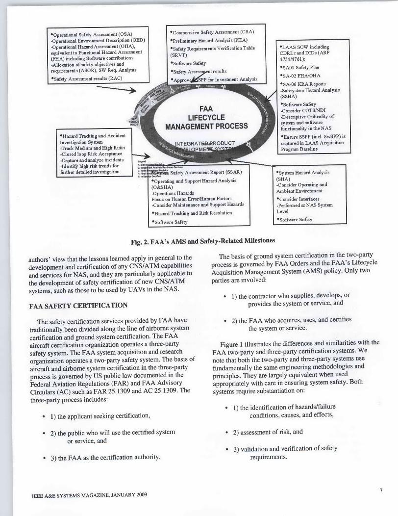
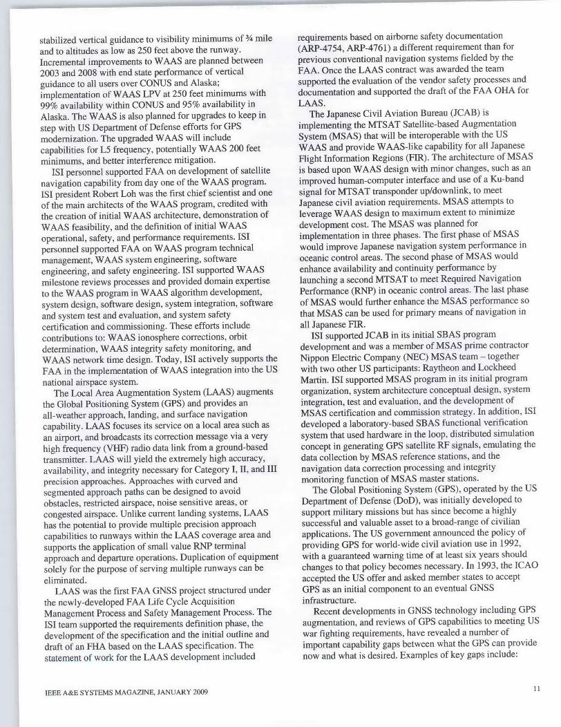
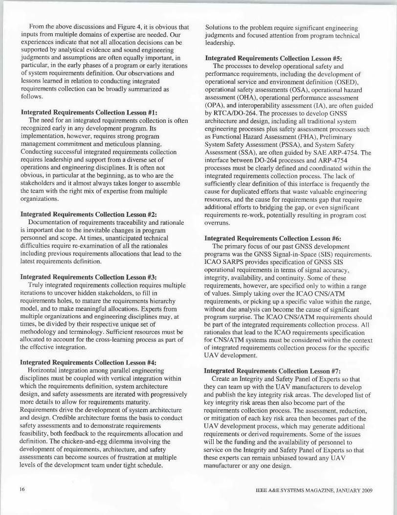
Fig. 3. Proposed Certification Organization for Galileo
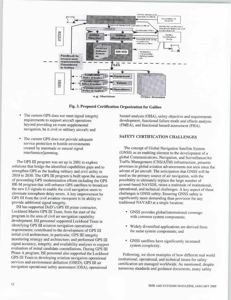
" The current GPS does not meet signal integrityrequirements to support aircraft operationsbeyond providing en-route supplementalnavigation, be it civil or military aircraft; and
" The current GPS does not provide adequateservice protection in hostile environmentscreated by manmade or natural signalinterference/jamming.
The GPS III program was set up in 2001 to exploresolutions that bridge the identified capabilities gaps and tostrengthen GPS as the leading military and civil utility in2010 to 2030. The GPS Ill program is built upon the successof proceeding GPS modernization efforts including the GPSIIR-M program that will enhance GPS satellites to broadcastthe new L5 signals to enable the civil navigation users toeliminate ionosphere delay errors. A key improvement byGPS III from the civil aviation viewpoint is its ability toprovide additional signal integrity.
151 has supported DoD's UPS III prime contractor,Lockheed Martin GPS III Team, from the start of theprogram in the area of civil air navigation capabilitydevelopment. 1ST personnel supported Lockheed Team inidentifying GPS Ill aviation navigation operationalrequirements; contributed to the development of GPS IIIinitial civil architecture, in particular, GPS III integritymonitoring strategy and architecture; and performed GPS IIIsignal accuracy, integrity, and availability analyses to supportevaluation of initial candidate constellations. During UPS IIIPhase A program, 151 personnel also supported the LockheedGPS Ill Team in developing aviation navigation operationalservices and environment definition (OSED), UPS III airnavigation operational safety assessment (OSA), operational
12
hazard analysis (OHA), safety objective and requirementsdevelopment, functional failure mode and effects analysis(FMEA), and functional hazard assessment (FHA).
SAFETY CERTI]FICATION CHALLENGES
The concept of Global Navigation Satellite System(GNSS) as an enabling element to the development of aglobal Communications, Navigation, and Surveillance/AirTraffic Management (CNS/ATM) infrastructure, presentspromises in global aviation advancements not seen since theadvent of jet aircraft. The anticipation that GNSS will beused as the primary source of air navigation, with thepossibility to ultimately replace the large number ofground-based NAVIDS, raises a multitude of institutional,operational, and technical challenges. A key aspect of thesechallenges is GNSS safety. Ensuring GNSS safety issignificantly more demanding than provision for anytraditional NAVAID at a single location:
* GNSS provides global/international coveragewith common system components;
" Widely diversified applications are derived fromthe same system components; and
* GNSS satellites have significantly increasedsystem complexity.
Following, we show examples of how different real worldinstitutional, operational, and technical issues for safetycertification are managed worldwide. As mentioned, despitenumerous standards and guidance documents, many safety
IEEE A&E SYSTEMS MAGAZINE, JANUARY 2009
E~Z
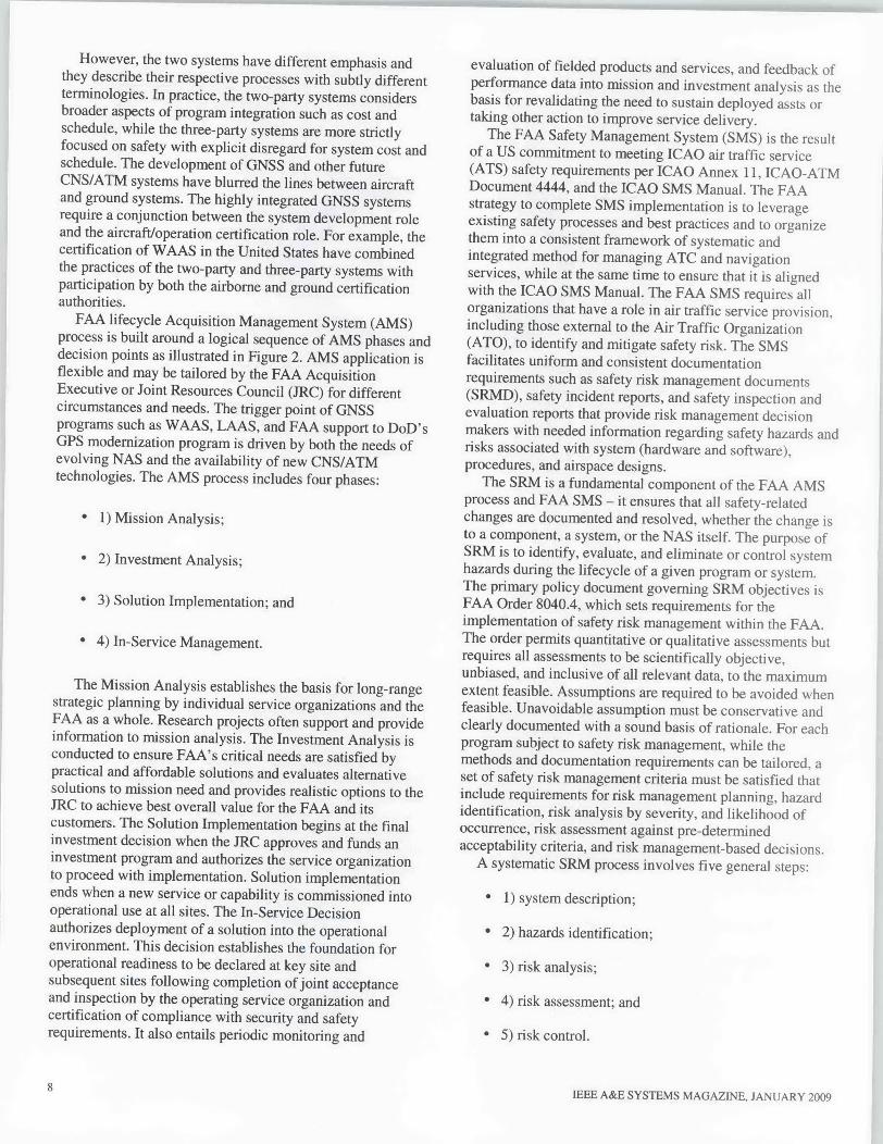
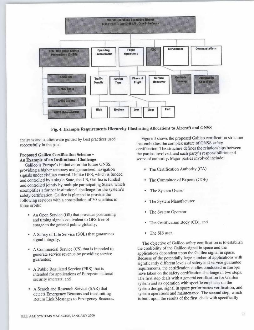
Fig. 4. Example Requirements Hierarchy Illustrating Allocations to Aircraft and GNSS
analyses and studies were guided by best practices usedsuccessfully in the past.
Proposed Galileo Certification Scheme -
An Example of an Institutional ChallengeGalileo is Europe's initiative for the future GNSS,
providing a higher accuracy and guaranteed navigationsignals under civilian control. Unlike GPS, which is fundedand controlled by a single State, the US, Galileo is fundedand controlled jointly by multiple participating States, whichexemplifies a further institutional challenge for the system'ssafety certification. Galileo is planned to provide thefollowing services with a constellation of 30 satellites inthree orbits:
" An Open Service (OS) that provides positioningand timing signals equivalent to GPS free ofcharge to the general public globally;
" A Safety of Life Service (SOL) that guaranteessignal integrity;
*A Commercial Service (CS) that is intended togenerate service revenue by providing serviceguarantee;
*A Public Regulated Service (PRS) that isintended for applications of European nationalsecurity interests; and
*A Search and Research Service (SAR) thatdetects Emergency Beacons and transmittingReturn Link Messages to Emergency Beacons.
IEEE A&E SYSTEMS MAGAZINE, JANUARY 2009
Figure 3 shows the proposed Galileo certification structurethat embodies the complex nature of GNSS safetycertification. The structure defines the relationships betweenthe parties involved, and each party's responsibilities andscope of authority. Major parties involved include:
* The Certification Authority (CA)
" The Committee of Experts (COE)
" The System Owner
" The System Manufacturer
* The System Operator
" The Certification Body (GB), and
* The SIS user.
The objective of Galileo safety certification is to establishthe credibility of the Galileo signal in space and theapplications dependent upon the Galileo signal in space.Because of the potentially large number of applications withsignificantly different levels of safety and service guaranteerequirements, the certification studies conducted in Europehave taken on the safety certification challenge in two steps.The first step deals with a general certification for Galileosystem and its operation with specific emphasis on thesystem design, signal in space performance verification, andsystem operations and maintenance. The second step, whichis built upon the results of the first, deals with specifically
13
each service or application's unique certificationrequirements. Another important factor in the Galileocertification structure is the use of the Committee of Experts.This committee is composed of experts similar to the FAA'suse of the WAAS Integrity Panel (WIP) of experts whohelped the WAAS system manufacturer identify key integrityrisk areas, assess their impact, perform integrity riskreduction or mitigation, and provide final approval before theWAAS system manufacturer can be certified by the FAA.
Integrated Requirements Collection -An Example of an Operational Challenge
The complexity in GNSS implementation and the highstakes of GNSS safety to achieve early ATC operationalbenefits make GNSS requirements definition both critical andchallenging. The need for an integrated requirementscollection is often recognized early, its implementation,however, is non-trivial. It is not obvious, particularly in thebeginning, who are the stakeholders and who are the systemrequirements drivers. To maximize and realize early GNSSbenefits to ATC, the ATC community must take a proactiverole in defining the GNSS operational requirements foraviation applications.
GNSS operational requirements are unique for each GNSSair navigation service. The operational requirements includeboth safety and performance requirements. The safetyrequirements specify a set of minimum requirements thatmust be satisfied to comply with the safety provisionspecified for the specific GNSS service. GNSS performancerequirements specify GNSS attributes that enable the GNSSservice provision within its operating environment, whichmay be different for different air navigation serviceproviders. For example, ATC automation to support andimprove safety may be implemented in some nations and notin others. The safety and performance requirements incombination with the operating environment then drive theGNSS design, implementation and safety certification inorder to achieve early ATC operational benefits.
Full participation by ATC community in GNSS integratedrequirements collection process is of particular importancefor three reasons:
* 1) The air navigation services provided byGNSS will undoubtedly form an essentialpart of the ATC environment in the future.
* 2) Almost all GNSS aviation applications mustbe certified in operational environments,which by all accounts the ATC will continueto play the critical role in ensuring the safe,orderly, and expeditious flow of air traffic.
* 3) The ATC environments are likely to incurfundamental changes with the introduction ofsuites of new CNS/ATM systems andcapabilities, and hence a deep, thorough, and
14
broad understanding of the current andfuture ATC environments are critical indeveloping correctly the GNSS operationalrequirements for air navigation.
In addition, we all know that requirements misgivings arecostly.
An example of ATC participation in GNSS requirementsdefinition may be illustrated in Figure 4, which shows therequirements hierarchy that allows for the allocation of therequired Total Navigation Service Performance for GNSS tomaintain Aircraft Operations Separation Minima in anoperational environment that involves ATC. The aircraftoperations may hypothetically be exposed to CHIT, mid-aircollision, or surface obstacles hazards for the analysis.Aircraft safety is achieved by maintaining minimumseparation from other aircraft and nearby obstacles. The safeseparation is maintained through pilot actions supported by acombination of ATS services such as navigation and ATCservices, aircraft surveillance, and controller-pilotcommunications services, and aircraft operatingenvironment. In addition, automation both on the ground,such as conflict alert, and in the aircraft, such as theminimum safe altitude warning, also helps to maintain therequired separations. Definition of aircraft safe separationminima is a function of the performance of GNSS navigationservice, aircraft operating environment including trafficdensity and aircraft characteristics and avionics, phase offlight or surface maneuver, and the performance andcapabilities of ATC, aircraft surveillance, and controller-pilotcommunications. Aircraft operating in a higher density areawith ATC in full workload may also need a larger separationminimum than aircraft operating in a lower density area.However, requirements for capacity eventually set thetradeoffs between safety and minimum separations.Obviously, the performance of ATC contributes directly tomaintaining the minimum separation requirements and theallocation of Total Navigation Service Performance forGNSS.
Safety assessments are a proven means to ensure thesafety of implementing complex, and technically challengingsystems. Safety assessments must interact with GNSSdevelopment processes at various stages of the program tosupport the GNSS requirements definition, architecturedevelopment, system design, implementation verification,certification, and service provision.
In the early stages of GNSS development, safetyassessments are frequently employed to support GNSSoperational safety and operational performance requirements(SPR) development, including primarily:
* 1) GNSS Operational Service & EnvironmentDefinition (OSED);
* 2) GNSS Operational Safety Assessment (OSA);and
IEEE A&E SYSTEMS MAGAZINE, JANUARY 2009
*3) GNSS Operational InteroperabilityAssessment (IA).
RTCAIDO-264 is often used as the guidance document inconducting OSED, OSA, and IA. Per RTCAIDO-264, OSEDdefines the navigation services that the GNSS provides andthe operating environment in which GNSS intends to operate.The OSED is a prerequisite of OSA, which may comprise:
* 1) Operational Hazard Assessment;
* 2) Operational Performance Assessment (OPA);and
* 3) An Allocation of Safety Objectives andRequirements (ASOR).
The output from OSA is SPR allocation to GNSSstakeholders.
The safety assessments are also frequently employed tosupport GNSS architecture development, system design, andimplementation, including primarily:
* 1) GNSS design Functional Hazard Assessment(FHA);
* 2) Preliminary System Safety Assessment(PSSA); and
* 3) System Safety Assessment (SSA).
SAE ARP-4754 is often used as the guidance document inconducting FHA, PSSA, and SSA. The input to FHAincludes the GNSS SPR, the GNSS OSED, and functionaldescription of GNSS architecture. The output from FHAforms part of the GNSS functional design analysis byidentifying potential functional failures and by providingclassification of hazards associated with specific failureconditions. The FHA conducted in the GNSS requirementsdefinition phase is used to support the initial assessment tocandidate design solutions to firm up requirements definition.The input to PSSA includes the FHA output and a completedescription of the GNSS architecture design. PSSAestablishes specific system level and sub-system level safetyrequirements.
The level of details in GNSS architecture design shouldallow PSSA to produce a meaningful preliminary indicationthat the system architecture can meet all identified safetyrequirements. The PSSA, if conducted in the GNSSrequirements definition phase, is used to further supportrequirements definition maturity. Participation by ATCcommunity impacts all phases of safety assessments.Analyses and assumptions for ATC contribute directly to theoutputs of OSED and OSA,
IEEE A&E SYSTEMS MAGAZINE, JANUARY 2009
INTEGRATED SAFETY REQUIREMENTSCOLLECTION AND DEFINITION
This section discusses lessons and observations that theseauthors gained through their participation in WAAS, LAAS,MSAS, and GPS III programs. The discussions focus onissues related to the first steps in any UAV safetycertification; namely, the integrated safety requirementscollection and definition.
Requirements definition is a key first element thatcontributes to the success or failure of any particular UAVdevelopment program. Requirement changes, incorrect orincomplete requirements are the most common cause ofprogram failures and cost overruns. The complexity in UAVcertification and safety implementation make UAVrequirements collection and definition both critical andchallenging. UAV operational safety requirements specify aset of minimum requirements that must be satisfied tocomply with the UAV safety provisions. UAV performancerequirements specify UAV attributes that enable UAVservice provisions within its operating environments of boththe UAV CNS/ATM systems and the civil aviationCNS/ATM systems. The UAV operational requirements,both safety and performance, drive UAV design,implementation, and safety certification requirements in itsoperational environment. Ideally, all requirements follow aclearly structured hierarchy that shows traceability eventuallyto a basic set of requirement drivers necessary to support safeUAV operations.
One example of UAV requirement driver for anyoperation in the NAS will be its contribution to maintainingaircraftlUAV separation during flight operations in the NAS.In the NAS, the UAV will be treated just like any otheraircraft. AircraftlUJAV safety for a given phase of light orsurface maneuver is achieved by maintaining minimumseparation from other aircraftlllAV and nearby obstacles.The safe separation is maintained through pilot actions (in thecase of UAV, remotely or through expert systems) supportedby a combination of ATS services such as navigation andATC services, aircraftlUAV surveillance and controller-pilotcommunications services, and aircraftlUAV operatingenvironment. Definition of aircraft and UAV safe separationminima is a function of the performance of the CNS/ATMservices; aircraft/UAV operating environment includingtraffic density and aircraft/UAV characteristics, phase offlight or surface maneuver, and the performance of ATC,aircraftlUAV surveillance, and controller-pilotcommunications. AircraftlUAV operating in a higher densityarea with ATC in full workload may also need a largerseparation minimum than aircraftlUAV operating in a lowerdensity area. Obviously, the performance of navigationservice contributes directly to maintaining the minimumseparation requirements. Figure 4 illustrated the requirementshierarchy allowing for the allocation of operationalrequirements from AircraftlUAV Operations SeparationMinima to the Total Navigation Service Performance forGNSS.
15
From the above discussions and Figure 4, it is obvious thatinputs from multiple domains of expertise are needed. Ourexperiences indicate that not all allocation decisions can besupported by analytical evidence and sound engineeringjudgments and assumptions are often equally important, inparticular, in the early phases of a program or early iterationsof system requirements definition. Our observations andlessons learned in relation to conducting integratedrequirements collection can be broadly summarized asfollows.
Integrated Requirements Collection Lesson #1:The need for an integrated requirements collection is often
recognized early in any development program. Itsimplementation, however, requires strong programmanagement commitment and meticulous planning.Conducting successfuil integrated requirements collectionrequires leadership and support from a diverse set ofoperations and engineering disciplines. It is often notobvious, in particular at the beginning, as to who are thestakeholders and it almost always takes longer to assemblethe team with the right mix of expertise from multipleorganizations.
Integrated Requirements Collection Lesson #2:Documentation of requirements traceability and rationale
is important due to the inevitable changes in programpersonnel and scope. At times, unanticipated technicaldifficulties require re-examination of all the rationalesincluding previous requirements allocations that lead to thelatest requirements definition.
Integrated Requirements Collection Lesson #3:Truly integrated requirements collection requires multiple
iterations to uncover hidden stakeholders, to fill inrequirements holes, to mature the requirements hierarchymodel, and to make meaningful allocations. Experts frommultiple organizations and engineering disciplines may, attimes, be divided by their respective unique set ofmethodology and terminology. Sufficient resources must beallocated to account for the cross-leamning process as part ofthe effective integration.
Integrated Requirements Collection Lesson #4:Horizontal integration among parallel engineering
disciplines must be coupled with vertical integration withinwhich the requirements definition, system architecturedesign, and safety assessments are iterated with progressivelymore details to allow for requirements maturity.Requirements drive the development of system architectureand design. Credible architecture forms the basis to conductsafety assessments and to demonstrate requirementsfeasibility, both feedback to the requirements allocation anddefinition. The chicken-and-egg dilemma involving thedevelopment of requirements, architecture, and safetyassessments can become sources of frustration at multiplelevels of the development team under tight schedule.
Solutions to the problem require significant engineeringjudgments and focused attention from program technicalleadership.
Integrated Requirements Collection Lesson #5:The processes to develop operational safety and
performance requirements, including the development ofoperational service and environment definition (OSED),operational safety assessments (OSA), operational hazardassessment (OHA), operational performance assessment(OPA), and interoperability assessment (IA), are often guidedby RTCAIDO-264. The processes to develop GNSSarchitecture and design, including all traditional systemengineering processes plus safety assessment processes suchas Functional Hazard Assessment (FHA), PreliminarySystem Safety Assessment (PSSA), and System SafetyAssessment (SSA), are often guided by SAE ARP-4754. Theinterface between DO-264 processes and ARP-4754processes must be clearly defined and coordinated within theintegrated requirements collection process. The lack ofsufficiently clear definition of this interface is frequently thecause for duplicated efforts that waste valuable engineeringresources, and the cause for requirements gap that requireadditional efforts to bridging the gap, or even significantrequirements re-work, potentially resulting in program costoverruns.
Integrated Requirements Collection Lesson #6:The primary focus of our past GNSS development
programs was the GNSS Signal-in-Space (SIS) requirements.ICAO SARPS provides specification of GNSS SISoperational requirements in terms of signal accuracy,integrity, availability, and continuity. Some of theserequirements, however, are specified only to within a rangeof values. Simply taking over the ICAO CNS/ATMrequirements, or picking up a specific value within the range,without due analysis can become the cause of significantprogram surprise. The ICAO CNS/ATM requirements shouldbe part of the integrated requirements collection process. Allrationales that lead to the ICAO requirements specificationfor CNS/ATM systems must be considered within the contextof integrated requirements collection process for the specificUAV development.
Integrated Requirements Collection Lesson #7:Create an Integrity and Safety Panel of Experts so that
they can team up with the UAV manufacturers to developand publish the key integrity risk areas. The developed list ofkey integrity risk areas then also become part of therequirements collection process. The assessment, reduction,or mitigation of each key risk area then becomes part of theUAV development process, which may generate additionalrequirements or derived requirements. Some of the issueswill be the funding and the availability of personnel toservice on the Integrity and Safety Panel of Experts so thatthese experts can remain unbiased toward any UAVmanufacturer or any one design.
16 IEEE A&E SYSTEMS MAGAZINE, JANUARY 200916
REFERENCES
[1] Yi Bian and Robert Lob,Experiences and Lessons Learned with GNSS Aviation Safety
Requirements Development,presented at the International Symposium on Certification of
Galileo Systems and Services (CERGAL 2005), 1115,April, 2005 in Braunschweig, Germany.
[2] Robert Loh, Dieter Guenter, Yi Bian, Narve Mjos and
Kenneth Kvinnesland,GNSS Aviation Safety Certification - Maximizing ATC Benefits
Through International Standardization,presented at the ATCA Annual Meeting in Dallas, TX,
November, 2005.
[3] Defense Science Board Study onUnmanned Aerial Vehicles and Uninhabited Combat AerialVehicles,
February 2004.
[4] General Accountability Office,Unmanned Aerial Vehicles - Improved Strategic and Acquisition
Planning Can Help Address Emerging Challenges,released March 9, 2005.
[5] Report for CongressUnmanned Aerial Vehicles: Background and Issues for Congress,
April 25, 2003.
[6] Office of Science and Technology Policy,UAVs in The Future Air Transportation System,
undated briefing by A. Martin Phillips.
[7] FAA Safety Management System Manual,version 1.1, May 21, 2004.
[8] FAA System Safety Handbook:Practices and Guidelines for Conducting System Safety Engineering
and Management,December 30, 2000.
[9] FAA Order 8040.4,Safety Risk Management,
June 26, 1998.
[10] FAA Advisory Circular,AC 25.1309-l1A, System Design and Analysis,
June 21, 1988.
[11] FAA Advisory Circular, AC 20-1 15B,RTCA Inc.
Document RTCAIDO- 17 8B, January 11, 1993.
[12] JAA, Advisory Circular,AC/AMJ 25.1309, System Design and Analysis,
June 10, 2002.
[13] RTCAIDO-178B,Software Consideration in Airborne System and Equipment
Certification,December 1, 1992.
[14] RTCAIDO-278,Guidelines for Communication, Navigation, Surveillance, and Air
Traffic Management (CNS/ATM) Systems Software Integrity
Assurance,March 5, 2002.
[15] RTCAIDO-264,Guidelines for Approval of the Provision and Use of Air Traffic
Services Supported by Data Communications,December 14, 2000.
[16] SAE ARP-4754,Certification Considerations for Highly-integrated or Complex
Aircraft Systems,November 1996.
[17] SAE ARP-4761,Guidelines and Methods for conducting the Safety Assessment
Process on Civil Airborne Systems and Equipment,1996.
[18] United States Military Standards,Mil-Std-882C, System Safety Program Requirements,
19 January 1996.
[19] MIL-STD-882D,DoD) Standard practice for System Safety,
10 February 2000.
IEEE A&E SYSTEMS MAGAZINE, JANUARY 2009
A