Embed Size (px)
Citation preview

UAV Data Exchange Test Bed for At-sea and
Ashore Information Systems
Yannick AllardHugues DemersMichel MayrandDan Radulescu
Prepared By: OODA Technologies Inc.4891 GrosvenorMontreal (Qc), H3W 2M2514.476.4773
Prepared For: Defence Research & Development Canada, Atlantic Research Centre9 Grove Street, PO Box 1012Dartmouth, NSB2Y 3Z7902-426-3100
Scientific Authority: Anthony IsenorContract Number: W7707-115137 and W7707-145677Call Up Number: 11 (4501076100) and 3 (4501133302)Project: 01jq, UAV Information Exchange and ExploitationReport Delivery Date: December 2, 2014
The scientific or technical validity of this Contract Report is entirely the responsibility of thecontractor and the contents do not necessarily have the approval or endorsement of Defence R&DCanada.
Contract Report DRDC-RDDC-2014-C297 December 2014
© Her Majesty the Queen in Right of Canada, as represented by the Minister of National Defence, 2014 © Sa Majesté la Reine (en droit du Canada), telle que représentée par le ministre de la Défense nationale, 2014

This page is intentionally left blank.
The Royal Canadian Navy (RCN) has articulated the need for more effective command teamsthrough the improved use of information. In particular, the RCN indicates the need for improvedinformation management techniques to promote greater situational awareness. In the maritimedomain, improvements could be realized through more effective use of data collected by sensorsand receivers onboard Unmanned Aerial Vehicles (UAV).
UAVs provide numerous capabilities such as persistent over-the-horizon surveillance, target acqui-sition, and reconnaissance. However, the data collected from a UAV will be best utilized whenintegrated with other information that taken collectively supports Maritime Domain Awareness.
This call-up explores the potential use of UAV collected data in both at-sea and ashore informationsystems. The basic idea is to establish a test bed specifically for testing UAV data exchange withat-sea and ashore information systems.
Data exchange will be investigated using instances of Coalition Shared Data Server (CSD). TheCSD is an implementation of the STANAG 4559 to ensure data discovery and interoperabilityamongst mission participants. The testbed will evaluate its synchronization capabilities in a lowbandwidth environment and explore the potential of using the CSD to store and retrieve AIS data.
In addition, a review and comparision of the current GCCS-M architecture and functionnalitieswith the upcoming MTC2 system is provided. A survey of UAV current and future sensor payloadsis also included.
i
The use or disclosure of the information on this sheet is subject to the restrictions on the title page of this document.
OODA Technologies Inc.

Final Report for RISOMIA Call-up 3
This page is intentionally left blank.
ii
The use or disclosure of the information on this sheet is subject to the restrictions on the title page of this document.

Contents
Contents iii
List of Figures vii
List of Tables ix
1 Introduction 1
2 Coalition Shared Data Server 3
2.1 Coalition Shared Data Server Description . . . . . . . . . . . . . . . . . . . . . . . 3
2.2 Coalition Shared Data Server and interoperability . . . . . . . . . . . . . . . . . . 4
2.2.1 NATO Standard ISR Library Interface . . . . . . . . . . . . . . . . . . . . . 4
2.2.2 NATO Secondary Image Format : STANAG 4545 . . . . . . . . . . . . . . 5
2.2.3 NATOGround Target Indicator Format Standard NATOAgreement (STANAG)4607 . . . . . . . . . . . . . . . . . . . . . . . . . . . . . . . . . . . . . . . . 7
2.2.4 NATO Motion Imagery Format . . . . . . . . . . . . . . . . . . . . . . . . . 7
2.2.5 NATO Tactical Data - Link16 format . . . . . . . . . . . . . . . . . . . . . 8
2.2.6 Other important NSIL data model . . . . . . . . . . . . . . . . . . . . . . . 9
2.2.6.1 NSIL Message View . . . . . . . . . . . . . . . . . . . . . . . . . . 9
2.2.6.2 NSIL Report View . . . . . . . . . . . . . . . . . . . . . . . . . . . 9
2.2.6.3 NSIL Collection Coordination and Information Requirements Man-agement . . . . . . . . . . . . . . . . . . . . . . . . . . . . . . . . . 10
2.3 Coalition Shared Data Server, NPR and SC2PS Installation . . . . . . . . . . . . . 10
iii

Final Report for RISOMIA Call-up 3
2.4 UAV Data Upload . . . . . . . . . . . . . . . . . . . . . . . . . . . . . . . . . . . . 12
2.5 Data Exchange between Coalition Shared Data Server instances . . . . . . . . . . . 12
2.5.1 Coalition Shared Data Servers Synchronization . . . . . . . . . . . . . . . . 12
2.5.1.1 Synchronisation setup . . . . . . . . . . . . . . . . . . . . . . . . . 13
2.5.2 Slowdown Mechanism . . . . . . . . . . . . . . . . . . . . . . . . . . . . . . 15
2.5.2.1 Kernel space . . . . . . . . . . . . . . . . . . . . . . . . . . . . . . 15
2.5.2.2 User space . . . . . . . . . . . . . . . . . . . . . . . . . . . . . . . 16
2.5.2.3 Advantages and disadvantages of both approaches . . . . . . . . . 16
2.5.2.4 The router . . . . . . . . . . . . . . . . . . . . . . . . . . . . . . . 17
2.5.2.5 NetLimiter . . . . . . . . . . . . . . . . . . . . . . . . . . . . . . . 20
2.6 Data Exchange Behavior in a network of Coalition Shared Data Server instances . 21
2.6.1 Scenario 1 : Connection failure before resynchronization . . . . . . . . . . . 22
2.6.2 Scenario 2 : Connection failure during synchronization . . . . . . . . . . . . 24
3 CSD Data Visualization 27
3.1 Visualization using SC2PS . . . . . . . . . . . . . . . . . . . . . . . . . . . . . . . . 27
3.1.1 Connect to a CSD with SC2PS . . . . . . . . . . . . . . . . . . . . . . . . . 28
3.1.2 Upload Motion Imagery from UAV with SC2PS . . . . . . . . . . . . . . . . 28
3.1.3 Query the CSD and visualize Motion Imagery with SC2PS . . . . . . . . . 28
3.1.4 Exporting video / imagery exploitation product to the CSD . . . . . . . . . 29
3.2 Visualization using NASA World Wind . . . . . . . . . . . . . . . . . . . . . . . . 30
3.3 Visualization using Quantum GIS . . . . . . . . . . . . . . . . . . . . . . . . . . . . 32
3.3.1 The CSD plugin . . . . . . . . . . . . . . . . . . . . . . . . . . . . . . . . . 33
3.3.2 Pros and cons of QGIS . . . . . . . . . . . . . . . . . . . . . . . . . . . . . . 33
3.3.2.1 Developing the plugin . . . . . . . . . . . . . . . . . . . . . . . . . 34
3.4 Remarks on Visualization . . . . . . . . . . . . . . . . . . . . . . . . . . . . . . . . 34
3.4.1 Interaction with the CSD . . . . . . . . . . . . . . . . . . . . . . . . . . . . 34
3.4.2 Extracting reports from the CSD . . . . . . . . . . . . . . . . . . . . . . . . 35
iv
The use or disclosure of the information on this sheet is subject to the restrictions on the title page of this document.

CONTENTS
4 Coalition Shared Data Server and the Global Positioning Warehouse 37
4.1 Naval Position Repository Installation . . . . . . . . . . . . . . . . . . . . . . . . . 37
4.2 CSD and NPR data structures comparison . . . . . . . . . . . . . . . . . . . . . . . 37
4.3 AIS and the CSD . . . . . . . . . . . . . . . . . . . . . . . . . . . . . . . . . . . . . 38
4.3.1 AIS Decoder Implementation . . . . . . . . . . . . . . . . . . . . . . . . . . 38
4.3.2 NIEM XML exchange standard . . . . . . . . . . . . . . . . . . . . . . . . . 38
4.3.3 AIS Data to CSD . . . . . . . . . . . . . . . . . . . . . . . . . . . . . . . . . 39
4.4 Data Exchange between CSD and NPR . . . . . . . . . . . . . . . . . . . . . . . . 41
5 Maritime Tactical Command and Control 43
5.1 Global Command and Control System - Maritime (GCCS-M) / DII COE . . . . . 43
5.1.1 GCCS-M / COE Concept and Architecture . . . . . . . . . . . . . . . . . . 44
5.1.2 The COE concept . . . . . . . . . . . . . . . . . . . . . . . . . . . . . . . . 44
5.1.3 The COE architecture . . . . . . . . . . . . . . . . . . . . . . . . . . . . . . 45
5.1.3.1 The COE kernel . . . . . . . . . . . . . . . . . . . . . . . . . . . . 45
5.1.3.2 The COE Infrastructure services . . . . . . . . . . . . . . . . . . . 46
5.1.3.3 The COE Common Support Application services . . . . . . . . . . 46
5.1.4 Data access and sharing . . . . . . . . . . . . . . . . . . . . . . . . . . . . . 47
5.1.5 Functionalities . . . . . . . . . . . . . . . . . . . . . . . . . . . . . . . . . . 48
5.2 Maritime Tactical Command and Control . . . . . . . . . . . . . . . . . . . . . . . 48
5.2.1 Architecture of the MTC2 - The as a Service technology . . . . . . . . . . 49
5.2.2 Data as a Service - Net-Centric Enterprise Services data strategy . . . . . . 50
5.2.2.1 Community of Interest . . . . . . . . . . . . . . . . . . . . . . . . 52
5.2.3 Infrastructure and Platform as a Service : The Consolidated Afloat Networksand Enterprise Service (CANES) . . . . . . . . . . . . . . . . . . . . . . . . 53
5.2.4 Software as a Service . . . . . . . . . . . . . . . . . . . . . . . . . . . . . . 55
5.3 Comparison of MTC2 and GCCS-M . . . . . . . . . . . . . . . . . . . . . . . . . . 56
6 UAV Sensors and Recommendations 59
v
The use or disclosure of the information on this sheet is subject to the restrictions on the title page of this document.
OODA Technologies Inc.

Final Report for RISOMIA Call-up 3
6.1 UAV Sensor Payload . . . . . . . . . . . . . . . . . . . . . . . . . . . . . . . . . . . 59
6.1.1 Imagery Intelligence . . . . . . . . . . . . . . . . . . . . . . . . . . . . . . . 60
6.1.1.1 Video/Electro-Optic/Infrared (EO/IR) Sensors . . . . . . . . . . . 60
6.1.1.2 Synthetic Aperture Radar (SAR) . . . . . . . . . . . . . . . . . . . 62
6.1.2 Signal Intelligence . . . . . . . . . . . . . . . . . . . . . . . . . . . . . . . . 63
6.1.3 Automatic Identification System Receiver . . . . . . . . . . . . . . . . . . . 64
6.1.4 Maritime Patrol Radar . . . . . . . . . . . . . . . . . . . . . . . . . . . . . . 65
6.1.5 Light Detection and ranging . . . . . . . . . . . . . . . . . . . . . . . . . . . 65
6.1.6 Laser Radar . . . . . . . . . . . . . . . . . . . . . . . . . . . . . . . . . . . . 66
6.1.7 Sensors in the context of maritime surveillance operations . . . . . . . . . . 66
6.1.8 Sensors in the context of maritime environmental operations . . . . . . . . 67
6.1.9 Sensor and information products in relation to the CSD capabilities . . . . 69
6.1.10 Summary and Recommendations for data simulation . . . . . . . . . . . . . 69
7 Difficulties and Conclusion 71
7.1 Difficulties encountered . . . . . . . . . . . . . . . . . . . . . . . . . . . . . . . . . 71
7.2 Conclusion . . . . . . . . . . . . . . . . . . . . . . . . . . . . . . . . . . . . . . . . 71
Bibliography 73
A Summary of UAV current sensor payload in the US Navy A-1
A.1 Example of currently fielded EO/IR payloads . . . . . . . . . . . . . . . . . . . . . A-1
A.2 Example of currently fielded SAR payloads . . . . . . . . . . . . . . . . . . . . . . A-1
A.3 Example of currently fielded SIGINT payloads . . . . . . . . . . . . . . . . . . . . A-2
A.4 Example of currently fielded AIS payloads . . . . . . . . . . . . . . . . . . . . . . . A-2
A.5 Example of currently fielded MPR payloads . . . . . . . . . . . . . . . . . . . . . . A-2
A.6 Sensor payload in development . . . . . . . . . . . . . . . . . . . . . . . . . . . . . A-3
A.7 Summary of UAV ant their current payloads . . . . . . . . . . . . . . . . . . . . . A-3
vi
The use or disclosure of the information on this sheet is subject to the restrictions on the title page of this document.

List of Figures
2.1 STANAGs based interoperabilty. . . . . . . . . . . . . . . . . . . . . . . . . . . . . 4
2.2 NATO secondary image format structure. . . . . . . . . . . . . . . . . . . . . . . . 6
2.3 WAN interface configuration . . . . . . . . . . . . . . . . . . . . . . . . . . . . . . 18
2.4 QoS configuration . . . . . . . . . . . . . . . . . . . . . . . . . . . . . . . . . . . . 19
2.5 Limiting bandwidth . . . . . . . . . . . . . . . . . . . . . . . . . . . . . . . . . . . 20
2.6 NetLimiter 3 Pro . . . . . . . . . . . . . . . . . . . . . . . . . . . . . . . . . . . . . 21
2.7 Initial state of CSD network . . . . . . . . . . . . . . . . . . . . . . . . . . . . . . . 22
3.1 NWW interface with AIS contacts . . . . . . . . . . . . . . . . . . . . . . . . . . . 31
3.2 CSD connection configuration window . . . . . . . . . . . . . . . . . . . . . . . . . 32
3.3 UAV coverage and video list . . . . . . . . . . . . . . . . . . . . . . . . . . . . . . . 33
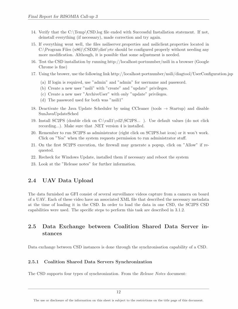
3.4 Video playing in Windows Media Player . . . . . . . . . . . . . . . . . . . . . . . . 34
3.5 QGIS with multiple layers shown . . . . . . . . . . . . . . . . . . . . . . . . . . . . 35
3.6 CSD plugin . . . . . . . . . . . . . . . . . . . . . . . . . . . . . . . . . . . . . . . . 36
3.7 CSD reports shown . . . . . . . . . . . . . . . . . . . . . . . . . . . . . . . . . . . . 36
4.1 AIS messages flow . . . . . . . . . . . . . . . . . . . . . . . . . . . . . . . . . . . . 40
5.1 GCCS-M / COE architecture. . . . . . . . . . . . . . . . . . . . . . . . . . . . . . 45
5.2 MTC2 as a Service architecture. . . . . . . . . . . . . . . . . . . . . . . . . . . . . 49
5.3 MTC2 as a Service architecture. . . . . . . . . . . . . . . . . . . . . . . . . . . . . 50
5.4 MTC2 Cloud-based CONOPS. . . . . . . . . . . . . . . . . . . . . . . . . . . . . . 51
vii

Final Report for RISOMIA Call-up 3
5.5 MTC2 Cloud-based CONOPS in case of DoS. . . . . . . . . . . . . . . . . . . . . 52
6.1 Still Imagery Technology Forecast. . . . . . . . . . . . . . . . . . . . . . . . . . . . 61
6.2 Videos Technology Forecast. . . . . . . . . . . . . . . . . . . . . . . . . . . . . . . 62
6.3 Radar Imagery Technology Forecast. . . . . . . . . . . . . . . . . . . . . . . . . . 63
6.4 Signal Intelligence Technology Forecast . . . . . . . . . . . . . . . . . . . . . . . . 64
6.5 Ocean weather image presenting waves heights and wind speed and direction . . . 68
viii
The use or disclosure of the information on this sheet is subject to the restrictions on the title page of this document.

LIST OF TABLES
List of Tables
5.1 Role of enterprise and COI towards data strategy goals . . . . . . . . . . . . . . . 53
6.1 Current and near-term capabilities of sensor types . . . . . . . . . . . . . . . . . . 69
A.1 Currently deployed UAV and available sensor payload . . . . . . . . . . . . . . . . A-3
ix
The use or disclosure of the information on this sheet is subject to the restrictions on the title page of this document.
OODA Technologies Inc.

Final Report for RISOMIA Call-up 3
This page is intentionally left blank.
x
The use or disclosure of the information on this sheet is subject to the restrictions on the title page of this document.

LIST OF TABLES
AIS Automatic Identification System
API Application Programming Interface
BAMS Broad Area Maritime Surveillance
C4ISR Command, Control, Communications, Computers, Intelligence, Surveillance andReconnaissance
CANES Consolidated Afloat Networks and Enterprise Service
CCD Charge-Coupled Device
CI Computer Infrastructure
COE Common Operating Environment
COI Community Of Interest
CSD Coalition Shared Data Server
DaaS Data as a Service
DEM Digital Elevation Model
DII Defence Information Infrastructure
DMS Discovery Metadata Specifiations
ELINT Electronic Intelligence
EO Electro-Optical
EO/IR Electro-Optic/Infrared
ESM Electronic Support Measures
GCCS Global Command and Control System
GCCS-M Global Command and Control System - Maritime
GIG Global Information Grid
GIOP General Inter-ORB Protocol
GMTI Ground Moving Target Indicator
GPW Global Positioning Warehouse
HSI Hyperspectral Imagery
IaaS Infrastructure as a Service
IMINT Imagery Intelligence
IMO International Maritime Organization
xi
The use or disclosure of the information on this sheet is subject to the restrictions on the title page of this document.
OODA Technologies Inc.

Final Report for RISOMIA Call-up 3
IR Infra-Red
ISR Intelligence Surveillance and Reconnaissance
ISS Integrated Sensor Suite
LADAR Laser Radar
LIDAR Light Detection And Ranging
MALE Medium Altitude - Long Endurance
MAJIIC Multi-intelligence All-source Joint ISR Interoperability Coalition
MASINT Measurement and Signatures Intelligence
MI Motion Imagery
MMSI Maritime Mobile Service Identity
MMSS Multimode Sensor/Seeker
MPR Maritime Patrol Radar
MP-RTIP Multi-Platform Radar Technology Insertion Program
MSI Multispectral Imagery
MSARI Maritime Situational Awareness Research Infrastructure
MTC2 Maritime Tactical Command and Control
MTI Moving Target Indicator
NCES Net-Centric Enterprise Services
NMEA National Marine Electronics Association
NIEM National Information Exchange Model
NPR Naval Position Repository
NSIF NATO Secondary Image Format
PA Project Authority
PaaS Platform as a Service
PolSAR Polarimetric SAR
QoS Quality of Service
RCN Royal Canadian Navy
SaaS Software as a Service
xii
The use or disclosure of the information on this sheet is subject to the restrictions on the title page of this document.

LIST OF TABLES
SAR Synthetic Aperture Radar
SC2PS Sensor Command and Control Planning Suite
SHADE Shared Data Engineering
SIGINT Signal Intelligence
SQL Structured Query Language
STANAG Standard NATO Agreement
TCPED Tasking, Collection, Processing, Exploitation and Dissemination
UA Unmanned Aircraft
UAV Unmanned Aerial Vehicle
UAS Unmanned Aerial System
XCOP Extensible Common Operating Picture
XML Extensible Markup Language
xiii
The use or disclosure of the information on this sheet is subject to the restrictions on the title page of this document.
OODA Technologies Inc.

Final Report for RISOMIA Call-up 3
This page is intentionally left blank.
xiv
The use or disclosure of the information on this sheet is subject to the restrictions on the title page of this document.

Part 1. Introduction
Part 1
Introduction
The Royal Canadian Navy (RCN) has articulated the need for more effective command teamsthrough the improved use of information. In particular, the RCN indicates the need for improvedinformation management techniques to promote greater situational awareness. In the maritimedomain, improvements could be realized through more effective use of data collected by sensorsand receivers onboard Unmanned Aerial Vehicle (UAV).
UAVs provide numerous capabilities such as persistent over-the-horizon surveillance, target acqui-sition, and reconnaissance. However, the data collected from a UAV will be best utilized whenintegrated with other information that taken collectively supports Maritime Domain Awareness.
Given the increasing role UAVs are going to play as part of wide area maritime surveillance, itis important to assess the interoperability of the data they provide and their compatibility withexisting or planned data infrastructure.
This call-up explores the potential use of UAV collected data in both at-sea and ashore informationsystems. The basic idea is to establish a test bed specifically for testing UAV data exchange withat-sea and ashore information systems.
Data exchange will be investigated using instances of Coalition Shared Data Server (CSD). TheCSD is an implementation of the Standard NATO Agreement (STANAG) 4559 ([4]) that ensuresdata discovery and interoperability amongst mission participants. The testbed will evaluate itssynchronization capabilities in a low bandwidth environment. In addition, it will explore thepotential of using the CSD to store and retrieve AIS data, which may be an important part of thedata collected by UAV and other surveillance assets in the maritime domain.
This test bed will also explore the feasibility of sharing UAV data between a CSD and NavalPosition Repository (NPR) instances. This will provide an assessment of the compatibility of dataprovided by a UAV platform to existing ashore information systems. Video and AIS data will beused as a starting point for this assessment.
This document, which is the final report for Call-up 11, is organized as follow :
• Section 2 presents a description of the CSD and the standards on which it is based. It de-
1
The use or disclosure of the information on this sheet is subject to the restrictions on the title page of this document.
OODA Technologies Inc.

Final Report for RISOMIA Call-up 3
scribes the CSD installation steps, its synchronization capabilities and the slowdown mecha-nism that was put in place to control network connection bandwidth between CSD instances.It also includes observations about the CSD behaviour when use in a network where multipleCSD instances are present.
• Section 3 presents the different visualization solutions that were investigated to support theCSD products.
• Section 4 presents a high level comparison of the structure of CSD database with the GlobalPositioning Warehouse (GPW) v2.0 (or NPR) database. It highlights the difficulties ofstoring video data feed obtained by a UAV in the NPR database, given the version that wasused as part of this Call-up. It also contains the description of the work that was performedto feed the CSD with AIS message, under a National Information Exchange Model (NIEM)XML format, retrieve them using the CSD metadata query interface, and store them in aNPR instance.
• Section 5 presents a review of the Common Operating Environment (COE) and the MaritimeTactical Command and Control (MTC2) at the architectural and functional level as the CSDis foreseen to support the data sharing and access strategy of the MTC2 and as such, thefuture version of the Global Command and Control System - Maritime (GCCS-M).
• Section 6 presents a review of available UAV sensor payloads, the information that canbe obtained from them and the relation of the sensor output to the CSD standard whereapplicable.
• Section 7 presents the difficulties encounter during the realisation of this Call-up and thegeneral conclusion of this document.
2
The use or disclosure of the information on this sheet is subject to the restrictions on the title page of this document.

Part 2. Coalition Shared Data Server
Part 2
Coalition Shared Data Server
This section presents a description of the CSD and the standards on which it is based. It alsopresents the CSD installation steps, its synchronization capabilities and the slowdown mechanismthat was put in place to control network connection bandwitdh between CSD instances.
2.1 Coalition Shared Data Server Description
The CSD is a server implementation of the STANAG 4559 NATO standard Intelligence Surveillanceand Reconnaissance (ISR) library interface. The standard Application Programming Interface(API) enable access to share repository of Ground Moving Target Indicator (GMTI), SyntheticAperture Radar (SAR), Electro-Optical (EO) and Infra-Red (IR) imagery, Motion Imagery (MI)as well as exploitation products and other relevant data that is generated and used by Multi-intelligence All-source Joint ISR Interoperability Coalition (MAJIIC) 2 collection assets and ex-ploitation systems.
The CSD concept was developed to address issues relating to availability and operational use ofMAJIIC 2 data namely :
1. Members may use the CSD to initiate their national system and complement it with infor-mation from coalition members systems;
2. The CSD can be used even if it suffered from communication failure as it will recover bysynchronizing back;
3. The CSD aims at the generation of the Common Ground Picture by providing access toGMTI, SAR, EO and IR imagery, MI and historical data;
4. The CSD removes the reliance on broadcast mechanism. Such a mechanism can place a hugestrain on the communication network by enabling information request and subscription todata/information of interest.
3
The use or disclosure of the information on this sheet is subject to the restrictions on the title page of this document.
OODA Technologies Inc.

Final Report for RISOMIA Call-up 3
2.2 Coalition Shared Data Server and interoperability
The data and information, as well as their describing metadata, which are stored within the CSDall follow a given standard to ensure interoperability between coalition members. Figure 2.1 showsthe different NATO standards used within a compliant CSD.
Figure 2.1: STANAGs based interoperabilty.
The following sections give the reader a brief overview of the different STANAGs involved in thecurrent CSD implementation.
2.2.1 NATO Standard ISR Library Interface
The STANAG 4559, the NATO Standard ISR Library Interface (NSILI), provides a standard foraccessing ISR libraries, reconnaissance databases, and product libraries of participating nations.It defines an interoperable interface to each participating Nation’s ISR library system, withoutaltering the internal architecture of any individual system. The basic concept of NSILI is forthe nations to place their ISR products on their own National server, and to make those productsavailable through the standard interface defined in STANAG 4559 to applications or users requiringthat information [4].
4
The use or disclosure of the information on this sheet is subject to the restrictions on the title page of this document.

Part 2. Coalition Shared Data Server
The interface provides electronic search and retrieval capabilities for distributed users to findproducts from distributed libraries in support of, but not limited to, rapid mission planning andoperation, strategic analysis, and intelligence preparation of the battlefield. Product Libraries andthe NSIL Interface are viewed as a key standards-based technology utilized within existing Requestfor Information (RFI) procedures [4].
Within the CSD, formats for ISR data are defined that include NATO Secondary Image Format(NSIF) (STANAG 4545) for multiple still images, text and graphics segments, and the relativeorientation of each with respect to the other segments of the image; NSIF also includes provisionsfor additional types and volumes of data that were not anticipated at the time the format standardwas created. Because of this continued expansion of applications of NSIF, the NSILI has been seento provide a discovery and retrieval capability for a variety of ISR data types. The flexibility ofNSILI has been proven with ISR Ground Moving Target Indicator (STANAG 4607) and DigitalMotion Imagery (STANAG 4609), which serve to prove the broader utility of NSILI [4].
The NSILI Client Application provides the user interface between a library and NATO users, andallows the client to use input from the user to discover a library server, search the library holdingsof various servers discovered, order products, and have digital data transmitted to the user [4].
In order to query for data or information products, the user relies on metadata attached to thesaid product. There may be two types of metadata supported. These are [4]:
1. Mandatory metadata. All servers are required to support queries involving these metadataand should make these metadata available where possible. They are described later in thissection.
2. Optional, metadata. These are metadata that are not required by the NSIL Interface. Usingthe discovery mechanism provided by the NSIL Interface, Clients can discover the optionalmetadata attributes supported by a particular library.
2.2.2 NATO Secondary Image Format : STANAG 4545
The NSIF (2.2) describes the format of digital images, Computer Graphic Metafile (CGM) graphics,text data and metadata that may be present within the NSIF file. It does not define the imagegraphic or text requirements of the host system. The host system is responsible for the handlingof unpacked image, graphic, and text data, as well as image, graphic and text display capabilities[5].
Though the STANAG 4545 was conceived initially to support the transmission of a file composedof a single base image, image insets (subimage overlays), graphic overlays, and text, the formatmakes it suitable for a wide variety of data file exchange needs. One of the flexible features ofthe NSIF is that it allows several Segments to be included in one NSIF File, yet any of the datatypes may be omitted. Thus, for example, the NSIF may equally well be used for the storage ofa single portion of text, a single image or a complex composition of several images, graphics, andtext. Information on other implementations can be found on the NSIF Registry on the Internet[5].
5
The use or disclosure of the information on this sheet is subject to the restrictions on the title page of this document.
OODA Technologies Inc.

Final Report for RISOMIA Call-up 3
Figure 2.2: NATO secondary image format structure.
One must also note that it is very common that NSIF contains text only data and no imagery. Itis very useful in a various range of missions where imagery cannot be shared.
Within the CSD implementation of the STANAG 4559, the NSIL IMAGERY VIEW providesimagery specific metadata attributes in addition to the core metadata set. While this view couldallow a server to expose imagery in formats different from STANAG 4545/NSIF (in which casethe MIME type attribute would reflect an image type different from NSIF), the server expects allimagery in this view to be in STANAG 4545 format. By introducing the ’part’ structure, a newrevision of the metadata model, the server now supports cataloguing NSIF files with more thanone image. Each image within the file is individually described in the metadata. The metadatamodel also supports description of reports with the NSIF file [4].
Here are some important notes about the NSIF file and the CSD implementation of the NSIL IMAGERY VIEW[4] :
1. An NSIF file doesn’t need to include an image segment to be a valid file according to STANAG4545. However, to be catalogued under the NSIL IMAGERY VIEW it will be required thatthe NSIF file contains a minimum of one image segment.
2. In the case of a streaming image the NSIL IMAGERY entity is optional in the NSIL IMAGERY VIEW;
3. In the case of a file-product the NSIL IMAGERY entity is mandatory;
6
The use or disclosure of the information on this sheet is subject to the restrictions on the title page of this document.

Part 2. Coalition Shared Data Server
2.2.3 NATO Ground Target Indicator Format STANAG 4607
The aim of the NATO Ground Moving Target Indicator Format (GMTIF), STANAG 4607, is topromote interoperability for the exchange of ground moving target indicator radar data amongNATO ISR Systems. Note that STANAG 4607 interprets the term ground moving target indicatorto mean targets on the surface of the earth, to include terrestrial, littoral, and deep water areas,stationary rotators, and targets flying at low speeds close to the surface of the earth [2].
The STANAG 4607 defines the data format for ground moving target indicator radar data, regard-less of the level of sophistication of the radar system and provides data that can be interpreted byany compliant ground system.
In addition to its use as a stand-alone format, the GMTI data can also be formatted in accordancewith this standard and then encapsulated in either of the NATO image formats (the NATO Sec-ondary or Primary Imagery Formats, STANAGs 4545 or 7023, respectively). This feature allowsadditional data, not included in this format, to be transmitted in conjunction with the GMTIdata [2]. GMTI information can also be disseminated through the NATO Standard ISR LibraryInterface (STANAG 4559).
Each server is responsible for receiving the incoming MTI data, storing it, and making it availableto the users as STANAG 4607 data via the NSIL Interfaces and the Communications Network. Thekey point is that the servers, the networks, and the user applications must conform to the STANAG4559 interoperable interface requirements [2], which is the case for the CSD implementation usedin this project.
In the CSD, the NSIL GMTI VIEW provides the specific metadata attributes in addition to thecore metadata set. The file type is application/x-cgmti. Files holding GMTIF data shall be binaryaccording to STANAG 4607 [4].
2.2.4 NATO Motion Imagery Format
The primary objective of the NATO Motion Imagery (MI) standard (STANAG 4609) is to providecommon methods for exchange of MI across systems within and among NATO nations [3].
Conformance with the STANAG 4609 will allow any compliant system to decode all compresseddata types (Standard Definition, Enhanced Definition, and High Definition) up to a minimum levelbut each Nation may choose to ORIGINATE one, two or all data types [3].
It also contain engineering guideline to facilitate integration of motion imagery products into theSTANAG 4559 data model. However, it seems that is strongly US based and it could be assumedthat future revisions of the STANAG 4609 will have corrected this [4].
Note also that it does not define a generic metadata set, but rather provides an example of ametadata set, the metadata set used for Predator generated video. It is assumed that a generic(non-Predator specific) metadata set will be developed, resulting in an updated and new mappingat some point [4].
7
The use or disclosure of the information on this sheet is subject to the restrictions on the title page of this document.
OODA Technologies Inc.

Final Report for RISOMIA Call-up 3
In the CSD, the supported video files are :
1. mp2t
2. mpeg
Motion imagery is stored in the CSD using the NSIL VIDEO VIEW data model. Specific infor-mation available as metadata for the NSIL VIDEO VIEW are :
1. Average Bit Rate;
2. Category;
3. Encoding Scheme;
4. Frame Rate;
5. Number of Rows;
6. Number of Columns;
7. Metadata Encoding Scheme;
8. MISM Level;
9. Scanning Mode.
2.2.5 NATO Tactical Data - Link16 format
The Link 16 interface is intended to provide improved information distribution, relative navigation,and identification capability in support of inter- and intra-Allied tactical command and controland mission execution functions. The purpose of STANAG 5616 is to specify the rules, protocols,and translations required between the J series and M series messages.
J and M messages are messages that exchange digital information among airborne, land-based,and ship-board tactical data systems. It is the primary means to exchange data such as radartracking information beyond line of sight. Link11, for M series messages, can be used on eitherhigh frequency or ultrahigh frequency. Link 11 relies on a single platform to report positionalinformation on sensor detections [37].
On the other hand, Link16, for J series messages, was designed as an improved data link usedto exchange near real-time information. It is a communication, navigation, and identificationsystem that supports information exchange between tactical Command, Control, Communications,Computers, Intelligence, Surveillance and Reconnaissance (C4ISR) systems. It provides secure,jam-resistant voice and digital data exchange [41]. All systems that forward data must adhere toSTANAG 5616 [1].
Within the CSD, Tactical Data Link data can be stored using the NSIL TDL VIEW data model.The supported file to be associated must be an application/x-nact-link16 file type, which is amodified Link 16 data made available as binary data files with the addition of the NACT header[4].
Specific information available as metadata for the NSIL TDL VIEW are [4]:
8
The use or disclosure of the information on this sheet is subject to the restrictions on the title page of this document.

Part 2. Coalition Shared Data Server
1. Activity : A number that together with the ’platform’ number defines the identity of a track;
2. Message Number : The Link 16 J Series message number;
3. Platform : A number that together with the ’activity’ number defines the identity of a track;
4. Track Number : Link 16 J Series track number for the track found in the product. The tracknumber shall be in the decoded 5-character format (e.g. EK627).
Since TDLs are networks on the battlefield that carry all manner of real-time messages, thiscategory encompasses diverse types such as Participant Position Location and Identification (PPLI)and tracking management messages. Because this Layer is not as mature, this Layer is likely tochange in future editions of the STANAG 4559 [4].
2.2.6 Other important NSIL data model
This section presents other types of data supported in the CSD within the their respective datamodel.
2.2.6.1 NSIL Message View
The NSIL MESSAGE VIEW is included in the CSD implementation to store and retrieve infor-mation relative to chat, email and any other form of communication. It is not meant to store anyISR related information product.
2.2.6.2 NSIL Report View
The NSIL REPORT VIEW is included to enable the server to better support cataloguing of ex-ploitation products, where exploitation products are defined as products that have been generatedmanually, semi automatically or automatically by processing a raw sensor product and enrich-ing it with information. Within the NATO there are several standardized report types availabledepending on the tasking, the types of sensors and the information needs [4]. These are :
1. Information Quality Report (IQREP);
2. Intelligence Report (ISRSPOTREP);
3. Motion Imagery Exploitation Report (MIEXREP);
4. Moving Target Indicator Exploitation Report (MTIEXREP);
5. Reconnaissance Exploitation Report (RECCEXREP);
6. WL Exploitation Report (WLEXREP).
This view will be used later on to store and retrieve encoded AIS message from the CSD.
9
The use or disclosure of the information on this sheet is subject to the restrictions on the title page of this document.
OODA Technologies Inc.

Final Report for RISOMIA Call-up 3
2.2.6.3 NSIL Collection Coordination and Information Requirements Management
The Collection Coordination and Information Requirements Management (CCIRM) Layer allowsthe Library implementing this STANAG to support some aspects of the CCIRM process. ThisLayer, along with the Reporting Layer and Associations in the Minimum Layer allow :
1) A CCIRM system to use the Library to provide tasking to sensor systems and exploitationsystems; 2) Sensor and exploitation systems to provide the results of the tasking back to theCCIRM system.
This view may return four different and mutually exclusive products, a Collection ExploitationPlan (CXP), an Intelligence Requirement, a Request For Information (RFI), a TASK and a Ge-ographic Area Of Interest (AOI). In the case of Geographic AOI being returned there will be no”part specific” parts. It is assumed that the RFI and the Geographic AOI are stored as XMLfiles accessible through the NSIL FILE.productURL. The Intelligence Requirement is an artificialmetadata-only product with no specialized attributes, it is only there as placeholder to allow as-sociations to be linked to a uniquely identified Intelligence Requirement entry. For details aboutan Intelligence Requirement the client will have to look at the content of a CXP file. The TASKis a metadata only product [4].
2.3 Coalition Shared Data Server, NPR and SC2PS Installation
Two instances of CSD were installed during the initial testing phase of this project. One wasinstalled under Windows 7 and the other was installed on a Windows XP operating system.
In order to install all the software correctly furnished as GFI (CSD, SC2PS and NPR), it isnecessary to perform the following steps :
1. Make sure that all the important updates from Windows are installed
2. Create C:\call11 directory and copy content from previous installations.
3. Create C:\Temp if it does not exist already
4. Correct the GPW template file NPR v6.sql and make sure that at line 234, the type ofTrackID ”smallint” is changed for ”int”
5. Install Microsoft SQL server (SQLEXPRWT x64 ENU.exe, the free version called Express,located in Common/.../Call-up 11/software).
(a) Select New Installation
(b) Accept licence and next
(c) Next
(d) Default Instance + next
(e) Next (don’t click on ”Use the same account...”)
(f) Default (Windows Auth. mode) + next
(g) Next
10
The use or disclosure of the information on this sheet is subject to the restrictions on the title page of this document.

Part 2. Coalition Shared Data Server
(h) IMPORTANT: authorize remote access to the database:
i. In MSSQL Studio, left panel, right-click on server, select Properties → connectionsand make sure that the checkbox ”Allow remote” is selected.
ii. Using the MS SQL Server Configuration Manager (separate tool in the start menu),Select SQL Server Network Configuration, Select Protocols, Select TCP/IP prop-erties, and select ”enable”. IMPORTANT: Restart the service using the same tool(in the main panel). If there is an issue, verify the Firewall to allow the connectionto the Database port. Sometimes, there is a popup from the firewall detecting theconnection attempt and requesting permission, in that case, click ”Allow”.
6. Using the MS SQL Studio tool, connect to the SQL server (it usually uses the laptop name)
(a) On the left side, click on the SQL server, click on databases with a right-click
(b) Select Create a new database
(c) Give the name CSD20 and click Ok
(d) Repeat the process for creating the NPR database
(e) Open the (corrected) file NPR v6.sql (within Studio), make sure that the database inthe drop down menu is not ”master” but ”GPW”, and click ”Execute!”
7. In the command prompt with administrator privileges, go to the C:\call11\CSD20\MsSqlSpatialdirectory and run the command:
(a) msscmd.exe -deploy -server=”NAME OF THE LAPTOP” -db=”CSD20”
(b) msscmd.exe -deploy -server=”NAME OF THE LAPTOP” -db=”GPW”
(c) The above commands installed the geospatial functionalities in both databases, it is theequivalent of PostGIS.
8. Install Java 1.6 (32bit NOT 64bit)(jdk-6u45-windows-i586.exe, located in Common/.../Call-up 11/software). CSD won’t work if you use Java 7 64bit. All defaut settings.
9. If you are skilled enough, remove the auto updated of Java.
10. Make sure that the environment variables (Control Panel → System → Advanced ... → EnvVariables) are set:
(a) JAVA HOME = C:\Program Files (x86)\Java\jdk...(b) Path = .......;C:\Program Files (x86)\Java\jdk..\bin
11. The provided CSD MSI installation exec file has a bug in it, it requires a D: drive. Insert aUSB Flash drive in the laptop to simulate that D: drive. This USB drive is also necessaryfor deinstalling the CSD server (from the Configuration Panel → Uninstall Program)
12. Open a Command Prompt window with Administrator Privileges (using the right click onthe Command Prompt icon)
13. In the command prompt, run the following command (adjust according to your settings):msiexec.exe /I ”C:\call11\cd1\SOURCES\CSD.msi” /quiet /L*V ”C:\Temp\CSD.log” IN-STALLDIRC DRIVE=”C:\” TARGETDIR=”C:\call11” DB LOCATION=”C:\Program Files\MicrosoftSQL Server\MSSQL10 50.MSSQLSERVER\MSSQL\DATA”
11
The use or disclosure of the information on this sheet is subject to the restrictions on the title page of this document.
OODA Technologies Inc.
Final Report for RISOMIA Call-up 3
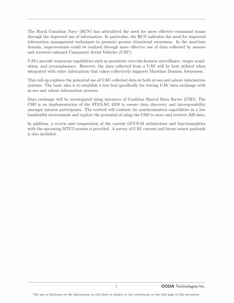
14. Verify that the C:\Temp\CSD.log file ended with Successful Installation statement. If not,deinstall everything (if necessary), made correction and try again.
15. If everything went well, the files nsiliserver.properties and nsiliclient.properties located inC:\Program Files (x86)\CSD20\dist\etc should be configured properly without needing anymore modification. Although, it is possible that some adjustment is needed.
16. Test the CSD installation by running http://localhost:portnumber/nsili in a browser (GoogleChrome is fine)
17. Using the brower, use the following link http://localhost:portnumber/nsili/diagtool/UserConfiguration.jsp
(a) If login is required, use ”admin” and ”admin” for username and password.
(b) Create a new user ”nsili” with ”create” and ”update” privileges.
(c) Create a new user ”ArchiveUser” with only ”update” privileges.
(d) The password used for both was ”nsili1”
18. Deactivate the Java Update Scheduler by using CCleaner (tools → Startup) and disableSunJavaUpdateSched
19. Install SC2PS (double click on C:\call1\cd2\SC2PS... ). Use default values (do not clickrecording...). Make sure that .NET version 4 is installed.
20. Remember to run SC2PS as administrator (right click on SC2PS.bat icon) or it won’t work.Click on ”Yes” when the system requests permission to run administrator stuff.
21. On the first SC2PS execution, the firewall may generate a popup, click on ”Allow” if re-quested.
22. Recheck for Windows Update, installed them if necessary and reboot the system
23. Look at the ”Release notes” for further information.
2.4 UAV Data Upload
The data furnished as GFI consist of several surveillance videos capture from a camera on boardof a UAV. Each of these video have an associated XML file that described the necessary metadataat the time of loading it in the CSD. In order to load the data in one CSD, the SC2PS CSDcapabilities were used. The specific steps to perform this task are described in 3.1.2.
2.5 Data Exchange between Coalition Shared Data Server in-stances
Data exchange between CSD instances is done through the synchronisation capability of a CSD.
2.5.1 Coalition Shared Data Servers Synchronization
The CSD supports four types of synchronization. From the Release Notes document:
12
The use or disclosure of the information on this sheet is subject to the restrictions on the title page of this document.

Part 2. Coalition Shared Data Server
Regular This type of synchronization only copies database entries from client to master CSD .When searching for the product, the products URL will display a link to the remote machine(client). The file location is on the remote machine. Following the provided URL link theproduct file will be made local to the master CSD .
Migration Only This type of synchronization will transfer database entries and make productslocal on the master CSD . The client CSD will still retain the copies and database entriesfor the synchronized products.
Migration and Product Deletion This type of synchronization will transfer database entriesand make products local on the master CSD . Once the product is fetched it will performvalidation that the product exists on the master CSD. If validation is correct it will proceedto DELETE the products (database entries and files) on the remote client. In order toDELETE, the user has to provide username and password with a updator valid role.
Delete Products and Database This type of synchronization will delete database entries andproduct files on the client CSD without any transfer. The product will be permanently loston the client CSD .
In other words, there are two models of synchronisation: regular and migration. In the first case,only the metadata is transferred, the actual file (if any) is kept on the original CSD . In the secondcase, migration, both the metadata and the file are transferred.
2.5.1.1 Synchronisation setup
In this section, we provide instructions on how to setup a synchronisation. Our instructions aremostly the same as those found within the Release Notes document, but with additional commentsoriginating from our experience in setting-up an actual synchronisation between two CSD instances.
Useful tips can be found in the live application by placing the mouse over a field and waiting fora tooltip to show.
Some definitions first. In the Release Note document, references to master and slave CSDs aremade. The difference between both is briefly given in the description of the regular synchronisationtype given above. It is: This type of synchronization only copies database entries from client tomaster CSD. From this we conclude that a client is the host from which files will be sent to themaster. Additionally, we understand that the master is also the CSD on which a synchronisationis setup. Thus:
Master : the CSD on which a synchronisation is set-up. The CSD that will receive new products.
Client : the CSD from which products are taken (copied from and possibly deleted).
In the following, the instructions given should be performed on the master CSD, the one to receiveproducts from the client.
13
The use or disclosure of the information on this sheet is subject to the restrictions on the title page of this document.
OODA Technologies Inc.

Final Report for RISOMIA Call-up 3
2.5.1.1.1 Remote endpoint of the client
The first step is to identify the client, the remote CSD from which product will be taken.
Enter the URL and IOR location in the Connection Point box. For a Canadian CSD the locationof the IOR file will be at: http://remote_address:portnumber/nsili/csd/ior
Where remote address is the IP address or domain name of the client CSD. The port number isfixed for Canadian CSDs and can be found in the CSD documentation.
For other client CSDs, the administrator must acquire the information from the remote CSDadministrator.
The user will then press the Get Library Id button. If the client CSD address information is correctand the client CSD is accessible the client CSD library name is inserted in the Subscribed CSDServer Library ID box.
The release notes state it is recommended the user enter the acquired library name into the OriginalData Source Library ID thereby implying this is an optional step. It is not. You must enter thesame information found in the field Subscribed CSD Server Library ID, i.e. the fields Original DataSource Library ID and Subscribed CSD Server Library ID should be the same. That might notbe the original intention, since entering a non-existent library id will result in no synchronisationtaking place and entering a valid library id that is not the same as the subscribed one will result in ablank page being served when validating the synchronisation later (when pressing add). Accordingto the release notes the original library id is there to help prevent circular synchronization of data.
2.5.1.1.2 Time interval and type of synchronisation
The user may choose a specific date time to filter synchronization products. If no entry is providedthe default time is the time of the initialization of the synchronization.
The user will then select archiving type (regular, migration, migration and product deletion ordelete only). The user will need to provide username and password for migration and productdeletion, and deletion only archiving types.
2.5.1.1.3 Starting the synchronisation
The user will then press the Add button and the synchronization properties will be added tothe local CSD synchronization file. If the configuration is correct the user can press the RestartSynchronization button to establish synchronization with the client CSD.
To remove an ongoing synchronization, select the CSD library to be removed, (check the removecheck box) and press the Remove button. The user needs to press the Restart Synchronizationbutton to definitely remove the library ID from the local CSD synchronization file.
14
The use or disclosure of the information on this sheet is subject to the restrictions on the title page of this document.

Part 2. Coalition Shared Data Server
2.5.1.1.4 Status
The status of an ongoing synchronisation can be seen by clicking on the Status entry of the top-leftmenu bar, then selecting Synchronisation at the bottom of the next page. The status shows whichsynchronisations are taking place and how many products have been transferred over differentperiods of time.
2.5.2 Slowdown Mechanism
Task 5 in the Call-up described a software implementation of a data exchange mechanism intendedto mimic bandwidth restriction (throttling) between two CSD instances. The restriction shouldgo from complete stoppage to none at all.
The goal presumably is to exercise the capability of a CSD to adjust to increased timeouts. Ac-cording to the Release Notes document, the following option needs to be modified (in the runtimescript of Tomcat C:\ProgramFiles(x86)\CSD20\dist\bin\run_tomcat.bat) when experiencingproblems related to a network slowdown:
-Dcom.sun.corba.transport.ORBTCPReadTimeouts=500:30000:5000:20
where the numbers are in this order:
1. initial time to wait in milliseconds,
2. max time to wait in milliseconds,
3. max time to wait for General Inter-ORB Protocol (GIOP) header in milliseconds, where theGIOP is the abstract protocol by which object request brokers communicate,
4. exponential backoff as a percentage when retrying.
These numbers should compensate for decreased bandwidth and latency.
Generally speaking, any slowdown mechanisms can be classified in two categories. Those operatingin kernel space and those operating in user space. In the following sections we explore both anddescribe their pluses and minuses.
2.5.2.1 Kernel space
All networking functions are implemented in kernel space, which refers to the space of memory re-served for running the privileged kernel, kernel extensions and most device drivers. The networkingstack is part of the kernel space and one cannot easily insert itself there to change its fundamentalbehavior. Tools must be used to manipulate settings in the kernel. These tools modify parametersaffecting the behavior of networking functions. Traffic control is one of those functions and we candistinguish the following:
15
The use or disclosure of the information on this sheet is subject to the restrictions on the title page of this document.
OODA Technologies Inc.

Final Report for RISOMIA Call-up 3
shaping the rate of transmission which is bandwidth throttling but also smoothing out bursts intraffic.
scheduling to improve interactivity, including reordering packets.
policing where control is exercised on incoming traffic.
dropping traffic exceeding a set bandwidth is simply dropped.
Thus one can achieve a high degree of customization by carefully modifying the kernel networkparameters. User-friendly tools to modify these parameters seem to be available for MS WindowsServer editions. We have not found any evidence of their availability in standard editions though.Linux however comes with these tools by default.
2.5.2.2 User space
User space is where most end-user applications reside. Most prominent in this category of appli-cations are the proxies. Those are processes listening for incoming connection on a given port andforwarding any requests to its destination. Sitting in the middle, an HTTP proxy, for example,can perform all kinds of operations like denying access to certain web sites, caching often requestedweb pages and most important here throttling bandwidth. These tools operate entirely in userspace and do not modify any underlying networking parameters.
There are tools that are not proxies and available under MSWindows that seem to operate partiallyin user space. The most popular are NetBalancer1 and NetLimiter2. They throttle bandwidth ofone process at a time, allowing to precisely fine-tune any slowdown.
2.5.2.3 Advantages and disadvantages of both approaches
How would someone best implement a network slowdown? So far we have identified three solutions:
1. Modify networking parameters of one host on the network through which traffic passes.
2. Use a tool like NetBalancer or NetLimiter.
3. Use a proxy
The first solution is an elegant one because of its generality. All traffic will be throttled. Not justHTTP in the case of an HTTP proxy for example. Also, and perhaps more importantly, it mimicsa real slowdown in the best way: at the network layer. However, these parameters are not easy tofine-tune. Their modification is best left to a dedicated throttling tool.
The second solution certainly makes use of such dedicated tools. NetBalancer for example, willthrottle all traffic to and from a particular process. We have experimented with NetLimiter 3 Pro
1http://seriousbit.com/netbalancer/2http://www.netlimiter.com/
16
The use or disclosure of the information on this sheet is subject to the restrictions on the title page of this document.

Part 2. Coalition Shared Data Server
under Windows 7 and it works as advertised allowing one to slow down to 1 byte per second anyprocess.
The third solution is a viable one as long as the protocol being proxied is HTTP and as long as theprocess being slowed down allows a change of configuration to point to a proxy first. Unfortunately,it does not appear the CSD is configurable in such a way.
Since it’s unclear how two CSDs communicate and since we do not know if they’ll continue commu-nicating the same way, we are proposing solution 1 above as the best one: modify kernel parameterto mimic a slowdown at the network layer. In order to best mimic a real slowdown it should bedone en route, on the wire. We mean by that a slowdown implemented by a middle-man sitting onthe wire between the two machines under tests, the ones hosting the master and slave CSDs. Andthe best device for this is a router. We are using a router with a modified, open-source firmwareoptimized for traffic control.
The main advantages for adopting such an approach is the generality of the solution. All traffic caneasily be throttled, not just a specific protocol. This also allows one to throttle an entire subnet,all computers behind the router can be throttled at the same time, very efficiently. Throttling cango as low as 1 kbps, that is 1024 bits per second or 128 bytes per second. The interface to changethis parameter is a standard web page easily accessible from any machine. The one drawbackhowever is that both CSDs need to be on different computers.
If that cannot be the case, we are suggesting using NetLimiter to slowdown the Apache processresponsible for running the CSD code (see figure 2.6).
2.5.2.4 The router
The router provided is a Linksys E2500 with a modified firmware, TomatoUSB. The E2500 waschosen precisely because the open source TomatoUSB firmware can be installed on it. As mostinexpensive routers today, it provide a wireless interface. However, for obvious security reasons wehave disabled this interface.
TomatoUSB is an alternative Linux-based firmware for routers with Broadcom chipsets. There aredifferent flavors of TomatoUSB each made and maintained by different individuals. The one wechose is by Shibby3, probably the most popular and user-friendly version.
TomatoUSB provides advanced Quality of Service (QoS) with 10 unique QoS classes defined, real-time graphs display, prioritized traffic with traffic class details and client bandwidth control viaQoS classes. One can throttle a single IP address to an entire subnet, down to 1 kbps, all througha simple web interface.
2.5.2.4.1 Initial configuration of the router
We are providing the router already configured for bandwidth limiting. Here we describe thesteps we took to do so. Access the router at 192.168.1.1 when connected on one of its LAN ports
3http://tomato.groov.pl/
17
The use or disclosure of the information on this sheet is subject to the restrictions on the title page of this document.
OODA Technologies Inc.

Final Report for RISOMIA Call-up 3
(the four blue ports). Default username and password were kept, it is admin in both cases. Werecommend changing those as soon as possible.
Figure 2.3: WAN interface configuration
The WAN interface configuration is shown in figure 2.3.
In Basic → Network (left navigation bar), you’ll find a section WAN/Internet. Under that section,modify the following parameters:
1. Choose Static from the Type dropdown menu.
2. Set the IP address of the router to 172.16.1.0
3. Set the subnet mask to 255.255.0.0
4. Set the gateway to 172.16.1.1
Details for enabling QoS are in figure 2.4.
In QoS → Basic Settings (left navigation bar), under section Basic Settings, check Enable QoS.Under section Outbound Rates/Limits, write 80000 in Max Bandwidth Limit.
The limiting Bandwidth interface is shown in figure 2.5.
In Bandwidth Limiter (left navigation bar), under section Bandwidth Limiter for Lan (br0), checkEnable Limiter. Write 80000 in both fields Max Available Download and Max Available Upload.
The initial configuration for limiting bandwidth is now done.
18
The use or disclosure of the information on this sheet is subject to the restrictions on the title page of this document.

Part 2. Coalition Shared Data Server
Figure 2.4: QoS configuration
2.5.2.4.2 Limiting bandwidth with the router
From the Bandwidth Limiter page (left navigation bar), one can find a table under section Band-width Limiter for Lan (br0). This table has the following fields:
IP | IP Range | MAC Address You can enter an IP address, or a range of those or a singleMAC address to which the following limits will be applied.
DLRate The target download rate, from 1 kilobit per second up to 99,999 kilobits per second.This rate is what we are trying to achieve. It might be a bit lower or a bit higher.
DLCeil The absolute maximum download rate. Above that, packets are dropped.
ULRate The target upload rate, from 1 kilobit per second up to 99,999 kilobits per second. Thisrate is what we are trying to achieve. It might be a bit lower or a bit higher.
ULCeil The absolute maximum upload rate. Above that, packets are dropped.
Priority The priority of the traffic coming from this source, i.e. whether or not it should beprocessed faster than other sources.
TCP Limit Maximum number of active connections for this source.
UDP Limit Maximum UDP connections that can be opened per second.
We suggest the following default value for all limiting rates:
19
The use or disclosure of the information on this sheet is subject to the restrictions on the title page of this document.
OODA Technologies Inc.

Final Report for RISOMIA Call-up 3
Figure 2.5: Limiting bandwidth
• Enter a range of IP addresses: 192.168.2-51. All IPs in this range will be bandwidth limited.
• Keep a Normal priority.
• Keep nolimit for both TCP Limit and UDP Limit.
To limit rate for all connected machines, simply enter the same desired rate in the fields DLRate,DLCeil, ULRate and ULCeil as in figure 2.5. You can go as low as 1 kbps or as high as 99,999kbps. One kilobit is 0.125 kilobytes or 125 bytes.
It is important to understand that bandwidth limiting occurs at the WAN-LAN interface. Machineson the same subnet, those within the 192.168.1.* subnet will not be limited. In practical terms,this means that one of the CSDs (we suggest the one representing the UAV, the client CSD) beconnected to the WAN port, the yellow one. The other CSD, the master which will receive datafrom the client, should be connected to one of the four LAN ports, the blue ones.
2.5.2.5 NetLimiter
We found NetLimiter superior in use over NetBalancer. NetLimiter is available at http://www.netlimiter.com/. Version 3 is necessary to run under Windows 7.
We ran into issues while testing NetLimiter 2 under Windows XP at very low rates of 500 bytes/sec.No such problems were experienced under Windows 7 or at higher rates.
20
The use or disclosure of the information on this sheet is subject to the restrictions on the title page of this document.

Part 2. Coalition Shared Data Server
2.5.2.5.1 Usage
A CSD runs under the Apache Web Server. It is that process that must be slowed down. Thename of that process is rather unfortunate, it is Commons Daemon Service Runner (see figure2.6). Rate limiting a process is as simple as checking the boxes under DL Limit and UL Limit anddouble clicking the numbers beside each checkboxes to adjust the rates.
Figure 2.6: NetLimiter 3 Pro
2.6 Data Exchange Behavior in a network of Coalition SharedData Server instances
This section presents the results and several observations related to the use of CSD instances ina network configuration. The proposed scenarios, described in sections 2.6.1 and 2.6.2, were notentirely tested as the CSD design prohibited some configurations and proved some assumptionswrong. Nonetheless, several interesting observations were made and are presented here. Theseobservations will highlight some behavior of the CSD which are not very well documented and willmake the reader more aware of how to synchronize CSD instances when they are placed inside acomplex network.
The initial state of the network is represented by figure 2.7. CSD A is the Master CSD and
21
The use or disclosure of the information on this sheet is subject to the restrictions on the title page of this document.
OODA Technologies Inc.

Final Report for RISOMIA Call-up 3
Figure 2.7: Initial state of CSD network
synchronize the product libraries created with CSD B and C. CSD C synchronize the productlibrary created with CSD D.
2.6.1 Scenario 1 : Connection failure before resynchronization
In the first tested scenario, a connection failure occurs between CSD A and CSD B and C. CSD Ais therefore isolated from the other CSD instances. Before the connection drops, all CSD instanceswere synchronized.
The steps realized to perform this scenario are :
• A network reconfiguration is made such that CSD C becomes the Master CSD, and CSD Bis now connected to C. Products are added to CSD B and D.
– Different products are added to both instances of CSD.
– The same product is added to both CSD instances.
• Wait until synchronization is over.
22
The use or disclosure of the information on this sheet is subject to the restrictions on the title page of this document.

Part 2. Coalition Shared Data Server
• Re-establish connection with A so that the network is at its initial state.
• Reconfiguration such that CSD A becomes the Master CSD, and CSD B and C are nowconnected to A (i.e remove the connection between B and C)
• Synchronize and observe the behavior of the products.
Some important observations were made during the testing of the scenario 1. First, the syn-chronization cannot be made blindly and this is a very important CSD concept. Lets considerthe three instances of CSD (A, C and D) from the initial configuration. Configuring CSD A tosynchronize with CSD C will not automatically retrieve all the products created on CSD D evenif those products are locally present in CSD C. It is not the entire product content of the CSDinstances which is synchronized, it is the different products libraries available and each instancecan contain multiple libraries. Its is important to know that each product created on particularCSD instance is part of a particular library linked to that particular CSD instance. Therefore, allproducts created in the CSD instance D are part of, lets say, library D. Products created in CSDinstance C are part of library C, and so on.
As an example, in order for CSD A to synchronize with products libraries C and D through CSDinstance C, two synchronization configurations must be defined (assuming that CSD instance C issynchronizing with the library D from CSD instance D):
• Retrieve library C products from CSD C;
• Retrieve library D products from CSD C.
And if CSD instance B would be connected to CSD instance C instead of being connected to CSDinstance A, we would have to set up another synchronization on CSD A to retrieve its productslibrary :
• Retrieve library B products from CSD C.
There is no way to configure the synchronization mechanism to retrieve all the libraries at onetime. This implies that if one wants to retrieve products from a particular library, he must beaware of the library existence and the location where this library is synchronized from.
It also means that CSD instances are particularly well suited for a bottom-up data exploitationwhere CSD instances in the middle of this bottom-up process produce enhanced products fromlower-level library. Therefore, only enriched information products reach the upper-level wheremore decisions are likely to be taken. The possibility of including a reference to a lower levelproducts also enable the retrieval of the original product from all the different layers.
Another important CSD concept is that the data products inside a CSD library can never bedeleted. Once a product is inserted in a CSD, there is no way it can be removed. This is madeper design. The only way to remove certain products from the result set of a particular query isto mark them as obsolete. An obsolete product will never come up in a product search and its fileURL will be removed from the metadata.
23
The use or disclosure of the information on this sheet is subject to the restrictions on the title page of this document.
OODA Technologies Inc.

Final Report for RISOMIA Call-up 3
This scenario was made to answer some questions related to our understanding of the CSD behav-ior. These questions along with our observations that relate to them are listed below.
• Is there a duplicate happening in the CSD A due to reconfiguration of the network?
No, there is no duplicate happening in A. The reason is pretty simple. Each product in alibrary has a particular Unique IDentifier (UID). Therefore, at synchronization time, onlyproducts with new UID or updated products are synchronized. It is believe that a check ismade on both the UID and the product update time during CSD libraries synchronization.
• Is there a duplicate happening in the CSD C due to reconfiguration of the network, and ifso, is the same product replicated 3 times in CSD A when the connection is re-established?
There is in this case a duplicate, but the product was not replicated 3 times. This is normalas they are not exactly the same product. They share the same content but do not haveexactly the same creation date and are not part of the same products library and thereforehave different UIDs. The CSD have no mechanism to explore the actual content of theproduct.
• Is the order in which the synchronization starts ( B to A before C to A) have an impact onthe synchronization process and outcome?
The order have no impact on the final state of the CSD instance A.
• What are the final states of each CSD instance at the end in terms of products content?
The content of CSD A and C is exactly the same.
• What is the difference on the synchronization process (migration versus regular) at the endon the content of the CSDs (products, metadata, etc. . . )?
No difference on the end content of the CSDs with the exception that the products are remoteand not local in the regular mode of synchronization.
2.6.2 Scenario 2 : Connection failure during synchronization
In the second tested scenario, a connection failure was planned to occur between CSD A and CSDB and C during synchronization. CSD A would therefore be isolated from the other CSD instances.At connection drop, CSD instances were still under synchronization process. CSD B and C wouldhave been sending products to CSD A.
The network would have been reconfigured such that CSD C becomes the Master CSD, and CSDB is now connected to C and time would have been allowed such that all synchronizations wouldhave been completed between B and C. Connection would then be re-establish between A andboth B and C.
This scenario was not possible. Both CSD B and C are not aware of the existence of CSD A. Assuch, both CSD instances sending their data to the instance A is not possible. CSD A control thesynchronization sequence and synchronize libraries in the order in which the administrator enteredthem in the synchronization configuration.
24
The use or disclosure of the information on this sheet is subject to the restrictions on the title page of this document.

Part 2. Coalition Shared Data Server
Another scenario was therefore designed to test if a product that was being sent to instance Aand to instance C would be taken again in A from C and would therefore create a duplicateentry. A looping in the CSD synchronization was attempted. It was interesting to see that such aconfiguration for synchronization is forbidden by design. As an example, lets consider the following:
• CSD A is configured to synchronize with library B through CSD B;
• CSD C is configured to synchronize with library B through CSD B.
If the administrator add the following synchronization configuration :
• CSD A to synchronize with library B through CSD C.
The CSD instance A will automatically drop the synchronization with library B through CSD B.Only one synchronization configuration per library per CSD is possible.
It is impossible to duplicate a library even when passing through several different CSD instances.
This scenario, even if not completed as intented, was made to answer some questions related toour understanding of the the CSD behavior. These questions along with our observations thatrelate to them are listed below.
• Verify that the product that was being sent to A has been sent to C. Is there a duplicate ofsaid product in CSD A when connection is re-established?
This question is no longer valid. However, no duplicate of a product ever occurs.
• If there is no duplicate, it could mean :
that C was not able to send its product as it was already existing and CSD A is waiting forCSD B to send it. Or C sent it and CSD A is managing this process all by itself.
The CSD synchronization mechanism is managing this process all by itself.
• What happens if B never reconnects? Will the product that was being transfer from CSD Bwill be accepted from CSD C or is it lost forever as CSD A is waiting for CSD B to reconnectsto finish its synchronization of the product?
A product is never lost, at least we did not observe this behavior.
25
The use or disclosure of the information on this sheet is subject to the restrictions on the title page of this document.
OODA Technologies Inc.

Final Report for RISOMIA Call-up 3
This page is intentionally left blank.
26
The use or disclosure of the information on this sheet is subject to the restrictions on the title page of this document.

Part 3. CSD Data Visualization
Part 3
CSD Data Visualization
This section presents three different options for the visualization of UAV data contained in theCSD.
The interaction with the CSD was tested using :
1. Sensor Command and Control Planning Suite (SC2PS) : a proprietary software labelled withthe Control Goods restriction;
2. NASA World Wind : an open-source Java-based Software Development Kit;
3. Quantum GIS : a open-source Geographical Information System where interface componentscan be developed using the C++ QT library and plugins can be added using the Pythonprogramming language.
It is important to note that the development made under NASA World Wind and QGIS areexploratory and were done in a very limited amount of time. They show the potential of eachlibrary and different options to interact with the CSD. More complete interface and interactivitycould be developed if one would devote more time in development.
3.1 Visualization using SC2PS
The SC2PS is a real-time, multi-sensor application to exploit data from soldier systems, ground-based sensor sources, tactical aerostats, and UAVs. SC2PS gives commanders a powerful tool foranalysis, mission planning, and decision making. SC2PS data is both Multilateral InteroperabilityProgram (MIP) compliant and CSD compatible.
The SC2PS was installed on both Windows XP and Windows 7 operating systems. However, thereis some problem under Windows 7 due to permission on writing and updating directories. Thelack of permission to write and update in the directory Runtime of SC2PS and all the directoriesbeneath is breaking many functionalities. However, SC2PS does not throw any error messagewith the exception of an inaccessible mission.dat file when trying to create an Event marker whenwatching a video previously loaded.
27
The use or disclosure of the information on this sheet is subject to the restrictions on the title page of this document.
OODA Technologies Inc.

Final Report for RISOMIA Call-up 3
Giving the user all the permissions on the Runtime directory and all the sub-directories will unlockall the functionalities of SC2PS.
3.1.1 Connect to a CSD with SC2PS
From the CSD Configuration Menu, the analyst must specify the following parameters :
1. User name
2. Password
3. Location of the CSD
4. Location of the CSD CORBA Initial Object Reference (IOR)
5. Time for wait
6. Number of connection attempts before failure
Once these parameters are correctly entered, simply press the Connect button.
3.1.2 Upload Motion Imagery from UAV with SC2PS
The upload of the UAV video data into the CSD was made using the SC2PS. In order to loadmotion imagery within the CSD, one must perform the following steps :
1. Click on the CSD menu;
2. Click on the CSD upload menu item
3. A window will appear, make sure the Auto-load XML is checked
4. Press the Add button and select the file you want to upload, note that they must be com-patible with the standard defined in the STANAG 4545, 4607 or 4609
5. Click the Open button
6. Click the Upload button.
3.1.3 Query the CSD and visualize Motion Imagery with SC2PS
In order to query the CSD to visualize the motion and still imagery from the UAV, one mustperform the following steps :
1. Open the CSD query window from the SC2PS CSD menu.
2. In the CSD Search Criteria panel, build a query that looks for all entries that are videos(or images) by ticking the of type = VIDEO (or of type = IMAGERY ) box. Run the queryusing the Search button on the top right of the window.
28
The use or disclosure of the information on this sheet is subject to the restrictions on the title page of this document.

Part 3. CSD Data Visualization
3. In the Query Results panel, all the found entries will be listed. There are 72 in our case.The thumbnail column however always displays a red X image for every entry.
Other metadata can be used as search criteria such as, but not limited to :
1. Creator of the file;
2. Title of file;
3. Geographic coverage and time window coverage;
4. Etc. . .
In order to view the data that have been returned as query results, the following steps are necessary:
1. Go in the query result tab (tabs are shown at the bottom of the query form);
2. In the Query Results panel tick one or more boxes in the Selected column to select whichentries to download.
3. Click the Download button to download the selected entries.
4. A pop-up window appears asking Download all products referenced by selected products?, clickyes. A new table will appear in the Product Download panel. Under the Download Statuscolumn, the status of the selected download briefly changes to Queued then the downloadstarts.
3.1.4 Exporting video / imagery exploitation product to the CSD
Video and imagery exploitation products can be created in SC2PS and exported to the CSD forarchiving. This would be a standard way to, for example, tag a particular frame in a video.
In order to do so, follow these steps :
1. Open a video :
(a) Click on the Video menu;
(b) Click on the Open video menu item, a window will appear;
(c) Click on the button with the directory icon;
(d) Select your video and click Open.
2. Press the Play button if the video does not start automatically
3. In order to tag a particular frame of the video :
(a) Press on the button with MILSTD symbol;
(b) A new element will appear in the Contacts directory of the Mission folder;
(c) Right-click on the newly created contact;
29
The use or disclosure of the information on this sheet is subject to the restrictions on the title page of this document.
OODA Technologies Inc.

Final Report for RISOMIA Call-up 3
(d) Click on the Create Intelligence Report or on the Create IExploitation Report, override/-modify/fill the metadata.
(e) Press the OK button.
(f) A new report will appear in the Reports folder within the Mission folder.
You can export the contacts and reports to the CSD by right-clicking on them and clicking on theExport to CSD contextual menu item.
3.2 Visualization using NASA World Wind
NASA World Wind is an open-source virtual globe developed by NASA and the open sourcecommunity for use on personal computers [42].It is a Java-based Sofware development Kit, enablingthe development of custom interface for geospatial data display and interaction.
World Wind can be expanded by using one of many add-ons - small extensions that add newfunctionality to the program. Possible types of add-ons [42]:
1. Point layers - simple XML files displaying placemarks (point of interest) as icons
2. Trail layers - paths (routes, boundaries)
3. Line features - XML with a list of points visualized as a line or wall
4. Polygon features - XML with a list of points visualized as a filled polygon (flat or extruded)
5. Model features - XML used to load 3D textured meshes
6. Place names - specific points (such as cities, hills and buildings) that are assigned text labelsImage layers - high resolution imagery for various places in the world
7. Scripts - files that control camera movement
This SDK provides all the necessary tools to develop a custom interface to visualize the productsfrom the CSD.
As an example of query and visualization, an interface to interact with the CSD has been developedwith the API provided in the SDK to showcase some of its capabilities. This interface is presentedin figure 3.1.
The CSD menu allows users to :
1. Connect to a CSD instance via a configuration window (represented in figure 3.2);
2. Query the CSD instance (queries are hardcoded for the moment retrieving all AIS and videoavailable);
3. Upload AIS contacts to the CSD via a file dialog window
4. Set the selected products as obsolete (Reports only);
5. Exit the program.
30
The use or disclosure of the information on this sheet is subject to the restrictions on the title page of this document.

Part 3. CSD Data Visualization
Figure 3.1: NWW interface with AIS contacts
The NPR menu allows users to transfer Automatic Identification System (AIS) contacts from theCSD to an NPR instance.
In the developed prototype, the AIS contacts are grouped into AIS tracks internally based on theirMaritime Mobile Service Identity (MMSI). All constructed tracks are displayed in the Track Tableon the upper left on the interface. The AIS tracks are displayed on the virtual globe using a reddot. They could be displayed using the MILSTD2525-A symbology available in the World WindSDK, however it would require more time to learn how to control the displayed information overthis symbology as the documentation is minimal. Right-clicking on the track symbol display apop-up window with track related information (Name, MMSI, Callsign, International MaritimeOrganization (IMO) number, Destination, etc...).
The UAV videos, on the other hand, are regrouped under the UAV coverage they are part of. Theavailable coverages and their approximate positions are listed in the UAV coverage Table on thelower left of the interface. These coverages are represented by yellow rectangles on the virtualglobe. Right-clicking on them provides the list of available videos (see figure 3.3). Clicking ona video will trigger the download of the file and the video will automatically open and play inWindows Media Player (see figure 3.4).
Clicking on an item on the Track or UAV Coverage tables will zoom at the item position on the3D globe.
The NASA WorldWind SDK enable the development of custom visualization and interaction soft-ware. It already provides the developer with a flexible framework. In addition, this frameworkcould be extended to suit particular requirements that are not yet supported by this SDK.
The main drawback of using the NASA WorldWind is that it is usually required for defence
31
The use or disclosure of the information on this sheet is subject to the restrictions on the title page of this document.
OODA Technologies Inc.

Final Report for RISOMIA Call-up 3
Figure 3.2: CSD connection configuration window
application to work offline. This requirement necessitate some change in the SDK configurationand package structure. Also, the image overlay of the 3D globe are downloaded in real time whileusing the SDK. Therefore, it is necessary browse the globe prior to putting the computer offlinein order to have image overlay when working with no internet connection.
To summarize, the NASA WorldWind SDK:
1. Provide a complete Java-based SDK enabling the development of custom software and inter-face;
2. Functionalities for the CSD are not clouded by any other interface component;
3. Can be integrated directly with the CSD API.
4. Can work offline with minor modifications;
5. Have moderate documentation and support but is relatively easy to use.
3.3 Visualization using Quantum GIS
QGIS is a free and open-source geographic information system. QGIS is an official project of theOpen Source Geospatial Foundation (OSGeo). There are numerous company offering commercialsupport for it. It runs on Linux, Unix, Mac OSX, Windows and Android and supports numerousvector, raster, and database formats and functionalities. It is built as a core set of functionsaugmented by a plugin system.
A screenshot of QGIS loaded with multiple layers is shown below in figure 3.5.
32
The use or disclosure of the information on this sheet is subject to the restrictions on the title page of this document.

Part 3. CSD Data Visualization
Figure 3.3: UAV coverage and video list
3.3.1 The CSD plugin
The plugin interfaces with the CSD through the web interface by making HTTP requests, specifi-cally POST requests. Product listings are retrieved by making an appropriate request and parsingHTML pages. There is no need to use the Java API directly. This choice of using the web inter-face is motivated by the fact that QGIS plugins are written in Python and re-using an existinginterface, the web one, is more efficient.
Reports are shown as MMSI labeled dots on the map. Videos are not displayed due to a lack ofdevelopment time.
The plugin interface provides fields to input the CSD hostname and port. Shown in figure 3.6 isthe CSD plugin interface.
The plugin will fetch products found in the map area currently displayed. A screenshot of a partof Africa is shown in figure 3.7 with reports found in that area.
3.3.2 Pros and cons of QGIS
QGIS is a tool for mapmakers. Its main purpose is to manipulate different layers of features likepoints, polygons, lines, etc. to gradually build a map. The final product is an image in a commonformat like gif or png. QGIS is not an interactive tool for purely visualizing maps, it’s use to buildthem rather.
This has consequences on the use-case at hand, namely showing CSD products on a map. First, itis slow at rendering a map. Whenever a new portion of a map is to be shown, e.g. by zooming or
33
The use or disclosure of the information on this sheet is subject to the restrictions on the title page of this document.
OODA Technologies Inc.
Final Report for RISOMIA Call-up 3
Figure 3.4: Video playing in Windows Media Player
panning, the rendering time is quite long. It’s not interactive. Second, QGIS feels too cumbersometo use for such a simple task. The intended use here is to zoom, pan and get at each report’sattributes, but these simple tasks are hampered by the slew of features offered by QGIS.
3.3.2.1 Developing the plugin
Here we report on the plugin development. The plugin architecture is based around a set of Pythonwrappers around the C++ API. Python calls are translated directly to C++. Because of this, nodocumentation exists for the Python API. The only documentation available is the C++ one andit is very scarce. The direct consequence of this is a very long and convoluted development time.
This is slightly offset by the fact that Python is a very expressive language greatly reducing anydevelopment time.
3.4 Remarks on Visualization
This section presents some remarks on the visualization development made under QGIS and NASAWorld Wind.
3.4.1 Interaction with the CSD
Two different approaches were tested :
34
The use or disclosure of the information on this sheet is subject to the restrictions on the title page of this document.

Part 3. CSD Data Visualization
Figure 3.5: QGIS with multiple layers shown
1. Using the Java API to connect and query the CSD with NASA World Wind;
2. Using the web service to query the CSD and retrieve the results with a Python code base.
It is worthwhile to mention the complete opposite could have been done (wrap the Java API andcall it from Python and use the web service from a Java code base). This remarks only illustratesthat various approaches can be made to connect and query the CSD, depending on a projectrequirements or programmer preferences.
3.4.2 Extracting reports from the CSD
Each reports must be extracted from the CSD by fetching an XML file using the web interface,i.e. making an HTTP call. That is one HTTP call by product. This is an I/O bound operationand is very time consuming. There are ways to reduce this time by making asynchronous calls,but we observed only a three-fold reduction in time. Great but not good enough for an interactivevisualization. Unfortunately, aside from making calls directly to a Java API function (whitoutusing a HTTP GET) there are no faster way of extracting products from the CSD.
35
The use or disclosure of the information on this sheet is subject to the restrictions on the title page of this document.
OODA Technologies Inc.

Final Report for RISOMIA Call-up 3
Figure 3.6: CSD plugin
Figure 3.7: CSD reports shown
36
The use or disclosure of the information on this sheet is subject to the restrictions on the title page of this document.

Part 4. Coalition Shared Data Server and the Global Positioning Warehouse
Part 4
Coalition Shared Data Server and theGlobal Positioning Warehouse
This section describes the work performed with regards to GPW v.2.0 or NPR. It details someconceptual differences between the structure of the CSD data model and the NPR database struc-ture.
4.1 Naval Position Repository Installation
The NPR instance was installed on a Windows 7 OS using the SQL script that was received asGFI. No particular steps was taken in the realisation of this task. No bug was detected and theinstallation went smoothly.
4.2 CSD and NPR data structures comparison
Some problems in the NPR database strucutre are preventing the storage of UAV video data tobe transfered in a NPR context. These are the following :
• UAV video data does not contain any identifiers of the observed entity. Therefore, any UAVdata sent to NPR would have to contain an UNKNOWN entity ID.
NPR’s purpose, as we understand it, is to keep track of the position of known entities (shipsmostly). Therefore, it might not make much sense, from the point of view of the NPRframework, to insert a lot of data that is not associated to any entity within the database.This is a problem of principle: Should the NPR database be filled with data that doesn’t fitits intended design?
• While NPR allows unknown as an entity identifier, there are indications within the GFI thatall contacts reporting an unknown entity essentially point to the same single entity entry -while they do in fact represent different entities.
37
The use or disclosure of the information on this sheet is subject to the restrictions on the title page of this document.
OODA Technologies Inc.

Final Report for RISOMIA Call-up 3
• Transferring images and videos from CSD to NPR could be difficult. They could theoreticallybe added to the GPW database as a binary blob but might also require the addition of newtables since the current ones only allow varchar data.
An alternate solution would be for the NPR database to contain only a web-link to a repos-itory location of the video or image. A CSD user would then have to follow the providedlink and download the media from the remote location. This is an easy implementation asfar as NPR is concerned but it shifts the problem to one of availability and accessibility ofthe added repository.
• As UAV data contains a coverage area stored as a polygon, an additional geometry tablewould be required within NPR, for its storage. The new table could be used as a genericgeometry metadata holder for contact reports. In other words, it should accept any objectof type geometry so that it may serve the purpose of storing other geometry types.
In conclusion, the current state of the NPR makes it impossible to store video data from a UAV.The lack of identity in the said video is the main problem. Also, the NPR allows varchar dataonly. If the NPR retains the attachment information for the old GPW, this should be investigatedas a possible solution once the entity ID problem have been solved.
4.3 AIS and the CSD
This section describes the work that was performed in relation to the decoding of AIS messagesand finding a solution to feed them to the CSD in order to retrieve them later on and store themin the NPR.
4.3.1 AIS Decoder Implementation
The implemented AIS decoder is essentially the same one used for Maritime Situational Aware-ness Research Infrastructure (MSARI) [34]. The decoder can handle all message types includingmessages that employ tag blocks. The Project Authority (PA) has indicated however that onlymessages 1 to 3 and 5 were of interest and as such, the mapping of data from AIS to XML wasimplemented only for this subset of message types.
4.3.2 NIEM XML exchange standard
The AIS data are sent to the CSD encoded, meaning that one must decode them when they retrieveit from the CSD. Under this call up, we built AIS decoders that decode the AIS message andrepresent it under the NIEM XML exchange standard. The NIEM is an XML-based informationexchange framework from the United States.
NIEM represents a collaborative partnership of agencies and organizations across all levels of gov-ernment (federal, state, tribal, and local) and with private industry. The purpose of this partner-ship is to effectively and efficiently share critical information at key decision points throughout the
38
The use or disclosure of the information on this sheet is subject to the restrictions on the title page of this document.

Part 4. Coalition Shared Data Server and the Global Positioning Warehouse
whole of the justice, public safety, emergency and disaster management, intelligence, and homelandsecurity enterprise. NIEM is designed to develop, disseminate, and support enterprise-wide infor-mation exchange standards and processes that will enable jurisdictions to automate informationsharing [38].
The NIEM is divided in several communities. The one of interest for AIS dissemination is the Mar-itime domain community. This community supports Maritime domain awareness, i.e the effectiveunderstanding of anything associated with the global maritime domain.
The schema description of the NIEM for the maritime domain can be downloaded from the NationalInformation Exchange Model web page https://www.niem.gov/technical/Pages/version-3.
aspx.
Using the .xsd files, one can build Java classes in order to integrate the standard exchange modelin its java code. However, it is not trivial. In order to create Java files the following steps arenecessary :
1. Download and unzip JAXB RI 2.2.7 from https://jaxb.java.net/2.2.7/
2. Create a bindings.xjb file to resolve name conflicts in the different schema. The bindings.xjbfile used to generate the Java code for this project is copied in the annexes of this document.
3. At the command line, under Linux, type the following : ./bin/xjc.sh -nv -extension -cplib/jaxb-impl.jar -b ./bindings.xjb -d ../generated path-to-niem/niem/domains/maritime/3.0/maritime.xsd.If you are using Windows, use xjc.bat instead of xjc.sh
4. Compile the Java classes and create the jar file. Make sure that all the jar files in the libdirectory of the JAXB package are first in the classpath as the JRE contains a faulty JAXBjar file.2
The niem.jar file generated for this project has been included in the deliverables.
4.3.3 AIS Data to CSD
The CSD as it was developed can support a wide range of ISR data. All the storage, query, accessand exchange mechanism are based on different NATO standards (STANAGs).
Currently, there is no accepted and implemented STANAG for AIS data. However, a work aroundis possible by considering an AIS report to be some kind of exploited raw sensor data.
Using this approach, a problem still remains. The NIEM XML structure of the AIS messagecannot be fitted in the currently supported standard in the CSD. We have therefore adopted awork around. The AIS message was stored in the CSD using the NSIL REPORT VIEW. As statedin the STANAG 4559, the NSIL REPORT VIEW is included to enable the server to better supportcataloguing of exploitation products, where exploitation products are defined as products that havebeen generated manually, semi automatically or automatically by processing a raw sensor productand enriching it with information [4].
39
The use or disclosure of the information on this sheet is subject to the restrictions on the title page of this document.
OODA Technologies Inc.

Final Report for RISOMIA Call-up 3
As mentioned in section 2.2.6.2, this view can refer to file products that contains pre-defined,supported report types. However, none of those report types contains all the place holder necessaryto store the AIS information. Therefore, a decision was made to store the complete AIS messageunder its NIEM XML structure under a XML node of a ISRSPOTREP message type. The NIEMXML message is stored within the SummaryOfCollectedInformation XML field. The XML-basedAIS message is enclosed within a ![CDATA[]] container in order to avoid any XML validation onit. Figure 4.1 represents the flow of the AIS messages from the encoded version of them to theNPR database.
Figure 4.1: AIS messages flow
There is however a major drawback. As the AIS messaging is not yet supported by a standard andis not implemented in the CSD, SC2PS cannot retrieve and display the AIS contacts on its display.Some modifications would therefore be required. Even with another software, custom modificationwould be necessary, as some query mechanisms, AIS decoders and display capabilities would haveto be added.
40
The use or disclosure of the information on this sheet is subject to the restrictions on the title page of this document.

Part 4. Coalition Shared Data Server and the Global Positioning Warehouse
4.4 Data Exchange between CSD and NPR
The slowdown of the data exchange between the CSD and the NPR instance is realized using therouter to limit the communication between two processes. However, in this case, a Java programis used to establish connection between the CSD and GPW as the AIS data must be queried,transformed and stored in the NPR instance.
UAV data exchanged between the CSD and NPR databases undergoes a conversion from ExtensibleMarkup Language (XML) format to Structured Query Language (SQL) insertion queries. Thecorrect container for UAV AIS reports of types 1-3, within the NPR database is a contact report.However, the structure of the NPR database makes it such that this transition between databasesis not always straightforward.
A contact report requires a reference to a known entity, navigational status, raw data and provider.Therefore, before an AIS contact report can be persisted, the corresponding entries to the previ-ously mentioned dependencies must either be found or generated.
The transition of AIS messages between the CSD and NPR databases has been successfully im-plemented for message types 1-3.
AIS messages of type 5 affect only entity data and metadata, their conversion from one databasemodel to the next was not possible during the time frame of this call-up.
41
The use or disclosure of the information on this sheet is subject to the restrictions on the title page of this document.
OODA Technologies Inc.

Final Report for RISOMIA Call-up 3
This page is intentionally left blank.
42
The use or disclosure of the information on this sheet is subject to the restrictions on the title page of this document.

Part 5. Maritime Tactical Command and Control
Part 5
Maritime Tactical Command andControl
This section presents an overview of architecture and functionalities of the GCCS-M, also knownas the Defence Information Infrastructure (DII) COE, and the MTC2, which is considered tobe the next generation of GCCS-M. It also presents a high level comparison of both systems.As the MTC2 documentation was not made available this study is based on information anddocumentation found on the internet such as MTC2 industry days presentations, technologiesroadmap and progress report from US agencies and publicly available contractual informationfrom the major US agencies involved in the MTC2 development such as Defence InformationSystem Agency (DISA).
5.1 Global Command and Control System - Maritime (GCCS-M)/ DII COE
In the past, most computing systems built for defense were stovepipe systems, i.e systems thatoperate in total isolation from the rest of the computing environment. This is in contrast to asystem of systems model, where data flows seamlessly from one business process to another.
The COE concept can be best described as being [7] :
1. An architecture and approach for building interoperable systems;
2. A reference implementation containing a collection of reusable software components;
3. An infrastructure for supporting mission-area applications;
4. A set of guidelines, standards and specifications that describes how to reuse software andhow to properly build new.
43
The use or disclosure of the information on this sheet is subject to the restrictions on the title page of this document.
OODA Technologies Inc.

Final Report for RISOMIA Call-up 3
5.1.1 GCCS-M / COE Concept and Architecture
The DII COE or GCCS-M 4.x is a framework for the creation of a set of cooperating computingenterprises. Its goals included the elimination of stove-pipe systems and cost reduction via softwarereuse, reduced need for system administration, and simplified system integration [15].
5.1.2 The COE concept
The DII COE was designed to be hardware independent; it operates on a range of operatingsystems running under standards-based systems. DISA has developed versions of the COE forWindows NT, and for a variety of flavors of Unix, including Solaris and HP [10].
The COE must be understood as a multifaceted concept which deals with 4 specific facets ([7],[22]):
1. A system foundation;
2. An architecture;
3. A reference implementation;
4. An implementation strategy.
As a System Foundation, the COE is a foundation for building other systems. Specific COEcomponents are selected by system designers to build their mission application. Each built systemuses the same API, the same approach to integration, and the same set of tools for enforcing COEprinciples [9].
As an architecture, the DII COE model is analogous to the Microsoft Windows paradigm. Itprovides a standard environment, a set of standard off-the-shelf components called segments, anda set of programming standards that describe how to add new functionality to the environment[20]. The DII COE is designed to run on PCs and workstations; it extends the Windows paradigm,which allows applications to coexist, by providing the capability for mission applications to sharedata and services/functions at the server level [10].
As a reference implementation, it means that algorithms and the way the algorithms are imple-mented are identical between different platforms, and the only differences are in the binary code.This reference implementation is the key to ensure interoperability and software reuse ([7], [22]).It might change over time to take advantage of new technologies or fix reported problems.
As an implementation strategy, it emphasizes incremental development and fielding to reduce thetime of integration of new functionality. It is a process of continually evolving the baseline to takeadvantage of new technologies as they mature and to introduce new capabilities([7], [22]). Thisstrategy also considers legacy systems and how such systems may be integrated into the COE [22].
44
The use or disclosure of the information on this sheet is subject to the restrictions on the title page of this document.

Part 5. Maritime Tactical Command and Control
5.1.3 The COE architecture
The architecture of the COE is presented in Figure 5.1 (from [11]). The concept of segment isthe first concept encountered by anyone when dealing with the DII COE. A segment is a unit ofsoftware or data that has been packaged such that it can be installed on a DII-compliant computerusing the software installation tool of the DII COE. All software that is to be installed on a DIIcomputer must first be put into segment format [15].
Figure 5.1: GCCS-M / COE architecture.
This concept facilitates software reuse. It forces the developer to prepare the software for inte-gration. Once in segment format, a software package can easily be transferred between programsoffices and used in a variety of contexts. Segments are defined as a collection of related functionsas seen from the perspective of the end user, not the developer [9].
The software that comprises the DII COE is placed into three categories: the kernel, the commonsupport applications, and the infrastructure services.
5.1.3.1 The COE kernel
Every computer that is to be a DII computer must have the kernel installed upon it. The COEkernel is the minimal set of software required on every platform regardless of how the platform
45
The use or disclosure of the information on this sheet is subject to the restrictions on the title page of this document.
OODA Technologies Inc.

Final Report for RISOMIA Call-up 3
will be used [10]. A DII COE kernel contains the operating system and windowing environment,but it will normally include several other features [9]:
1. a basic System Administration function,
2. a basic Security Administration function,
3. an Executive Manager function (e.g., a desktop GUI such as Windows NT or CommonDesktop Environment),
4. a utility for creating privileged operator login accounts,
5. a utility for creating nonprivileged operator login accounts, and
6. COE tools for segment installation.
Most of these functions are provided by COTS products, and in the case of NT, may even beprovided by the operating system itself. The COE kernel is used to define and establish the basicruntime environment context that an operator inherits when he logs in (among other actions, thistypically means to establish which environment variables are defined and their initial setting). Thekernel is intentionally designed to be as small as possible, to be as much COTS as possible, toprovide a common starting point for loading segments to build up the system, and to provide anextensible but common runtime environment for segment execution. The segment concept andmission specific application capabilities are discuss in the next section [10].
5.1.3.2 The COE Infrastructure services
The infrastructure services are largely independent of any particular application, They include :
1. Networking, system and security administration services;
2. Communication service to send /receive data;
3. Distributed computing services;
4. Print services;
5. Multimedia / collaborative services;
6. Web servers;
7. Data access services at the database and file management level.
The infrastructure services are services that are deemed to be of general use [15].
5.1.3.3 The COE Common Support Application services
These services are much more specific to particular mission domain. They include :
1. Alert Service for routing, prioritizing and managing alert messages;
46
The use or disclosure of the information on this sheet is subject to the restrictions on the title page of this document.
Part 5. Maritime Tactical Command and Control
2. Correlation service which correlates information from sensors and other sources of informa-tion;
3. Mapping and cartography service to handle the display of maps and imagery;
4. Messaging service to parse and distribute military format messages;
5. Web browsers;
6. Data access services for common data access methods.
The common support applications are desktop applications that are deemed to be of general use[15].
GCCS-M, as we know it, is composed of the COE core segments and mission specific applicationsegments.
5.1.4 Data access and sharing
COE enforces the concept of a system of systems, where multiple systems are able to freely andeasily access and share data. This is achieved by the COE Shared Data Engineering (SHADE)component. This component includes :
1. The Data Access application part of the Common Support Applications and;
2. The Global Data Management and the Data Management services part of the InfrastuctureServices.
The SHADE approach provides the engineering techniques and components which COE developerscan employ to resolve data sharing problems. Use of SHADE did improved data consistency, reduceredundancy, and promote true data interoperability. SHADE does not rule out multiple copies ofthe same data created for performance sake, but it does manage the duplication to ensure that alldatabases are kept synchronized [9].
The main problem is that information is not easily shared. Communications between GCCS-Mnodes are made between pre-determined point to point connections within systems and applica-tions on disparate networks. A producer ”pushes” information to predefined consumers [8]. Thisinformation push can have significant effect on the network load as some of the pushed informationmight not be necessary for some particular subscriber.
Some other challenges related to the COE information sharing concept are [8]:
1. User might be unaware that information exists;
2. User knows it exists but cannot access it;
3. User can access it but cannot exploit it due to a lack of understanding.
The network centric data strategy that will be presented later will address these weaknesses.
47
The use or disclosure of the information on this sheet is subject to the restrictions on the title page of this document.
OODA Technologies Inc.

Final Report for RISOMIA Call-up 3
5.1.5 Functionalities
Also, the information output is mainly related to situational awareness (i.e Recognized MaritimePicture), which is represented as tracks and maps. It is not able to address the needs of the navywith regards to the planning and execution of missions.
Global Command and Control System (GCCS) limitations stem from the fact that each militaryService found it necessary to produce a tailored version of GCCS to support individual Servicemissions. This has led to limitations on a Task Force Commander’s ability to use common applica-tions, share data and coordinate planning activities, drawbacks that are most obvious when jointoperations are being planned and executed. As an example, GCCS-Joint baseline and ExtensibleCommon Operating Picture (XCOP) baseline.
5.2 Maritime Tactical Command and Control
This section describes the architecture of the MTC2 and provides an overview of some of its corefunctionalities.
According to [14], the United States Navy information technology strategy is in need of changedue to operational inefficiencies and interoperability problems. Ships and submarines have beenforced to integrate various redundant systems in order to provide vital mission critical intelligence.The end result of these inefficiencies is as follows:
1. Loss of command and control agility and responsiveness;
2. Unacceptable timeframes to replace legacy systems;
3. Limited bandwidth per sailor;
4. Aging technology that is cost prohibitive to replace;
5. Limited reuse of technology;
6. Network security vulnerabilities.
On a high level, fundamental differences are from a paradigm shift from need to know to need toshare. Also, there is the as a Service technology which is included in all levels of the underlyingMTC2 architecture.
MTC2 will also provide apps to fill gaps at the Force Level and Maritime Operation Center. Theas a Service technology will also greatly facilitate rapid software delivery and software reuse andtherefore reduced the cost of system development and enable new technology to be tested andfielded more easily.
The MTC2 system will be based around the concept of network centric enterprise system and buildon Google/Amazon-like Cloud Architectures. It will leverage the Navy’s computing infrastructureprovided by the Consolidated Afloat Networks and Enterprise Service (CANES). MTC2 is planningto field to the MOCs in late FY14.
48
The use or disclosure of the information on this sheet is subject to the restrictions on the title page of this document.

Part 5. Maritime Tactical Command and Control
5.2.1 Architecture of the MTC2 - The as a Service technology
This section presents the expected architecture of the MTC2. From a bottom up perspective, theMTC2 architecture will be made of four levels of services, namely :
1. Data as a Service;
2. Infrastructure as a Service;
3. Platform as a Service;
4. Software as a Service.
Figure 5.2 (from [13]) represents the as a Service architecture concept while Figure 5.3 (from [18])presents this architecture in relation to the MTC2.
Figure 5.2: MTC2 as a Service architecture.
In addition, MTC2 is expected to be built on Google/Amazon-like cloud architectures. Therefore,as represented by figure 5.4 and figure 5.5 (both from [18]), in case of network problem, it couldreorganize itself into more regional cloud temporarily while waiting to be connected to the maincloud again.
The following sections describe all of the as a Service layers that are part of the MTC2 architecture.Their role, the underlying technology as well their benefits and drawbacks are presented.
49
The use or disclosure of the information on this sheet is subject to the restrictions on the title page of this document.
OODA Technologies Inc.

Final Report for RISOMIA Call-up 3
Figure 5.3: MTC2 as a Service architecture.
5.2.2 Data as a Service - Net-Centric Enterprise Services data strategy
Data as a Service (DaaS) is a cousin of Software as a Service (SaaS) (described later). Like allmembers of the as a Service family, DaaS is based on the concept that the product, data in thiscase, can be provided on demand to the user regardless of geographic or organizational separationof provider and consumer. Additionally, the emergence of service-oriented architecture (SOA) hasrendered the actual platform on which the data resides also irrelevant [36].
DaaS brings the notion that data quality can happen in a centralized place, cleansing and enrichingdata and offering it to different systems, applications or users, irrespective of where they were inthe organization or on the network. As such, DaaS solutions provide the following advantages [36]:
1. Agility - Users can move quickly due to the simplicity of the data access and the fact thatthey don’t need extensive knowledge of the underlying data.
2. Cost-effectiveness - Providers can build the base with the data experts and outsource thepresentation layer, which makes for very cost-effective user interfaces and makes changerequests at the presentation layer much more feasible.
3. Data quality - Access to the data is controlled through the data services, which tends toimprove data quality, as there is a single point for updates.
Interoperability is also a strategic goal of the Net-Centric Enterprise Services (NCES) Data Strat-
50
The use or disclosure of the information on this sheet is subject to the restrictions on the title page of this document.

Part 5. Maritime Tactical Command and Control
Figure 5.4: MTC2 Cloud-based CONOPS.
egy. Interoperability is the ability to share information among components while preserving itsaccuracy, integrity and appropriate use. Usability requires the technical condition of interoper-ability (mapping and matching) plus understandability through data component definitions anddescriptions [27]. The data strategy of the MTC2 offers the following in support of the interoper-ability goal [27]:
1. Make data sets understandable by publishing associated semantic and structural metadatain the Metadata Registry or federated registry.
2. Enable mission and business processes, including their semantics and data structures, tobe reused where possible and mediated where required through careful componentizing andregistration of associations.
3. Decentralize data management to Community Of Interest (COI) to allow prioritization andcollaboration based on immediate operational needs while providing enterprise infrastructurefor self-synchronization on a larger scale.
Note that the CSD implementation of the STANAG 4559 supports the DaaS as seen by the MTC2.
The adoption of a network centric data strategy within the MTC2 resolves the problem where
51
The use or disclosure of the information on this sheet is subject to the restrictions on the title page of this document.
OODA Technologies Inc.

Final Report for RISOMIA Call-up 3
Figure 5.5: MTC2 Cloud-based CONOPS in case of DoS.
information is not easily shared across different systems. According to [8], it will enable a movefrom :
1. Pre-determined point to point connections within systems and applications on disparatenetworks;
2. Producer pushes information to predefined consumers.
to the following situation :
1. Systems and applications are web-service enabled to expose their information;
2. Authorized known and unanticipated consumers pull or subscribe to what they need regard-less of who produced the information.
5.2.2.1 Community of Interest
A COI is an organizational construct for working collaboratively to establish clusters of datainteroperability that cross formal boundaries. COIs are important because they make explicit and
52
The use or disclosure of the information on this sheet is subject to the restrictions on the title page of this document.

Part 5. Maritime Tactical Command and Control
widely visible (publish names, advertisements of what they are doing, who’s involved etc.) vitalinformation sharing task groups that would not otherwise be even recognized as organizations [27].
COIs are generally responsible for publishing and managing metadata via the Metadata Registryand its federates as well as formulating and managing rules concerning usage of the net-centriccapabilities they offer [27].
With regards to the goals of the NCES data strategy, both the COIs and the enterprise thatprovides the services have a important role to play in order to achieve them.
Table 5.1: Role of enterprise and COI towards data strategygoals
Goal Enterprise COI
Make data visible
Maintain Discovery MetadataSpecifiations (DMS) to facili-tate search; develop and main-tain enterprise search capabil-ity
Tag data holdings with DMS,extend for COI specific crite-ria; register access services inenterprise service registry
Make data accessible
Maintain repository of accept-able standards for web-basedservices; develop and main-tain enterprise federated ser-vice registry
implements access services
Make data understandable
Maintain Metadata registry.develop and maintain feder-ated metadata registry for se-mantic and structural meta-data
Develop and maintain vocabu-laries, taxonomies for data ex-change; register these agree-ments in metadata registry
5.2.3 Infrastructure and Platform as a Service : The Consolidated Afloat Net-works and Enterprise Service (CANES)
Today’s environment is typified by dedicated hardware for specific applications. Information istied to the application, the location and the operating system. This approach can lead to poorutilization of computing resources and require additional hardware and software to be purchasedto accommodate dynamic usage and future growth [29].
Net-centric Computing Infrastructure will leverage distributed computing resources to provideinfrastructure that appears to the end-users or applications as one virtual capability. Sharedcomputing and data storage resources will be virtually allocated and the mechanism for doing
53
The use or disclosure of the information on this sheet is subject to the restrictions on the title page of this document.
OODA Technologies Inc.

Final Report for RISOMIA Call-up 3
so will be transparent to users. By virtualizing how users view the computing infrastructure,an organization can begin reducing technical and administrative barriers to sharing resources,and provide more agile and scalable support for information sharing [29]. Net-centric computerinfrastructure is usually defined as Infrastructure as a Service (IaaS).
IaaS is a provision model in which an organization outsources the equipment used to supportoperations, including storage, hardware, servers and networking components. The service providerowns the equipment and is responsible for housing, running and maintaining it [32].
Characteristics and components of IaaS include [32]:
1. Utility computing service.
2. Automation of administrative tasks.
3. Dynamic scaling.
4. Desktop virtualization.
5. Policy-based services.
6. Internet connectivity.
On the other hand, Platform as a Service (PaaS) is a category of cloud computing services thatprovides a computing platform and a solution stack as a service. In a PaaS model, the consumercreates the software using tools and/or libraries from the provider. The consumer also controlssoftware deployment and configuration settings. The provider provides the networks, servers,storage, and other services. PaaS offerings facilitate the deployment of applications without the costand complexity of buying and managing the underlying hardware and software and provisioninghosting capabilities [39].
PaaS offerings may also include facilities for application design, application development, test-ing, and deployment as well as services such as team collaboration, web service integration, andmarshalling, database integration, security, scalability, storage, persistence, state management,application versioning, application instrumentation, and developer community facilitation.
MTC2 will use IaaS and PaaS layers that are supported in the United States by the ConsolidatedAfloat Networks and Enterprise Service (CANES) program. The fundamental goal of CANESis to bring IaaS and PaaS, within which current and future iterations of Tasking, Collection,Processing, Exploitation and Dissemination (TCPED) computing and storage capabilities willreside. CANES will provide complete infrastructure, inclusive of hardware, software, processing,storage and end user devices for Unclassified, Coalition, Secret and Sensitive CompartmentedInformation for all basic network services (email, web, chat, collaboration) to a wide variety ofNavy surface combatants, submarines, Maritime Operations Centers, and Aircraft [25].
CANES is based around a cloud computing architecture that will host applications. Throughthis approach the Navy goal is to provide a common computing environment that will rely oncommercial off the shelf equipment. By decoupling hardware from software, this will improveefficiency and reduce cost.
GCCS-M / MTC2 will be early adopter of the CANES implementation. Eventually other appli-cations, systems and data sources will be added to provide an on-demand system synonymous
54
The use or disclosure of the information on this sheet is subject to the restrictions on the title page of this document.

Part 5. Maritime Tactical Command and Control
with cloud computing. By reducing complexity, eliminating proprietary systems and providingimproved scalability and adaptability the the organization adopting MTC2 should realize moreflexibility to changing conditions. Cost savings will be realized as the need for infrastructure,energy and staffing to manage the new system will be reduced [14].
The benefits of moving toward IaaS and PaaSe are, according to [29] :
1. Reduced complexity : existing capabilities have grown through independent acquisitions ofcomponents without an overall vision or architecture in mind. The emerging best practicesfor large-scale data center operations will drive simpler, more consistent infrastructures.
2. Better responsiveness : The ability to monitor the Global Information Grid (GIG) infras-tructure across all applications, services, and user groups, along with the ability to responddynamically to data storage and processing load will make it easier, faster and less expensiveto allocate additional resources to meet new, unanticipated demands.
3. Shared Computer Infrastructure (CI) Resources : With the ability to share resources dy-namically among applications, services, and user groups, peak transient CI demand for anapplication or service can be met by prioritization of the CI pool and by providing availableinfrastructure resources dynamically in response to priority uses.
4. Increased consolidation opportunities : With the ability to share processing and storage, theneed to build excess capacity in every individual application’s hardware in order to meetincreased or unexpected user demand will be eliminated. This will have a dramatic positiveeffect on the overall cost of operations.
5.2.4 Software as a Service
SaaS is a software delivery model in which software and associated data are centrally hosted onthe cloud. SaaS is typically accessed by users using a thin client via a web browser [40].
Several important changes to the software market and technology landscape have facilitated ac-ceptance and growth of SaaS solutions [40]:
1. The growing use of web-based user interfaces by applications, along with the proliferation ofassociated practices continuously decreased the need for traditional client-server applications.
2. The standardization of web page technologies (HTML, JavaScript, CSS), the increasing popu-larity of web development as a practice, and the introduction and ubiquity of web applicationframeworks gradually reduced the cost of development.
3. The increasing penetration of broadband Internet access enabled remote centrally hostedapplications to offer speed comparable to on-premises software.
4. The introduction and wide acceptance of lightweight integration protocols such as REST andSOAP enabled affordable integration between SaaS applications (residing in the cloud) withinternal applications over wide area networks and with other SaaS applications.
SaaS eliminates the need to install and run the application on the customer’s own computer.
55
The use or disclosure of the information on this sheet is subject to the restrictions on the title page of this document.
OODA Technologies Inc.

Final Report for RISOMIA Call-up 3
Within the MTC2, web-services should offer the operator with tools to support the entire rangeof command and control functions [13] i.e planning, execution, monitoring and assessment.
5.3 Comparison of MTC2 and GCCS-M
The differences between COE and MTC2 are noticeable both at the architecture and functionalpoint of view.
Concerning the data access and sharing, there is a paradigm shift to need to share in the MTC2,i.e, share your data first then process and share the information products. This is made so thatsome people have a quicker access to raw data to process them and generate more informationproducts more quickly.
Also, where COE is a point to point data exchange between known producer and consumer, theMTC2 presents the data as a Service where one subscribes to a topic regardless of the dataproducer. Also, data are discoverable using a metadata registry, data catalogs, metadata discov-ery. MTC2 resolves many challenges of the COE architecture for data visibility, availability andunderstandability.
At the architectural level, there are several differences. At the infrastructure and platform levels,COE components and computer resources resides in each and every operator’s work station. COEcan be installed on a limited subset of available operation system and its components are tightlycoupled with the OS on which it is installed. These systems lack scalability in computing powerand storage.
MTC2 relies on the as a Service technology for both its infrastructure and platform. Using a cloud-like architecture, storage and computing power are scalable and can be shared and prioritized.This approach decouples hardware and software. This model also greatly reduces cost of softwaremaintenance and deployment as everything is centralized.
At the software level, COE ensure software reuse and capability deployment through the use ofSegments. Those segments must be built according to very strict specifications and must passindependent verification and validation to obtain a certain compliance level before being fielded.These new capabilities are then installed on the targeted computer to be available for a very limitednumber of operators. Each and every operator that wants or needs the new capability must haveit installed on their own computer.
MTC2 relies on web services to deploy its capabilities. The mission specific applications reside ona remote computer, and are therefore available to anyone. The development of such web servicesobey well defined standards. These web services are discoverable, that means that searching withina service registry, one can find and use the capability it needs anywhere, anytime. This approachreduces software development cost, deployment time and the dependency of having to deal with asystem administrator.
At the functionality level, the difference is also significant. GCC Systems provide simple trackson a map, which supports situation awareness only. Also the information available about a par-ticular track is limited to spatio-temporal information. Very little information is available about
56
The use or disclosure of the information on this sheet is subject to the restrictions on the title page of this document.

Part 5. Maritime Tactical Command and Control
tracks status, operational readiness and current tasking. Much more information will be readilyavailable within MTC2. MTC2 will present the operator and decision makers with the so-calledinformation halo. This information halo will provide dynamic Command and Control, anchoredby enhanced situational awareness through rapid-access to relevant data associated to tracks (fuelstatus, ammunition loadout, manning, casual reporting, mission readiness, plans and tasking).
In addition to the enhanced situational awareness, the planned architecture and software deploy-ment technology of MTC2 will address identified gaps in operational and tactical Maritime C2requirements. As such the planned MTC2 will be [18] :
1. More complete by offering Planning, Execution, Monitoring and Assessment tools to allowcommander’s to seek answers to ”What is,” ”What next,” ”What if,” and ”What was”.
2. More collaborative across echelons and mission partners (joint and multi-national ) to allowCommanders to plan and re-plan, in near real time from decentralized locations that supportthe tactical situation.
3. More cohesive by offering Integrated, seamless and interoperable data exchange across ISR,IO, Cyber, combat systems, and combat support functions
57
The use or disclosure of the information on this sheet is subject to the restrictions on the title page of this document.
OODA Technologies Inc.
Final Report for RISOMIA Call-up 3
This page is intentionally left blank.
58
The use or disclosure of the information on this sheet is subject to the restrictions on the title page of this document.

Part 6. UAV Sensors and Recommendations
Part 6
UAV Sensors and Recommendations
This section presents a review of UAV related documentation describing the roadmap plan forthe development of future Unmanned Aerial System (UAS). It presents the current and futurecapabilities of the sensor payloads.
Based on those reviews, recommendations are provided on data to simulate in order to further testthe CSD capabilities for the formation of maritime domain awareness.
6.1 UAV Sensor Payload
The role of the Maritime UAV system is to provide unmanned, long endurance, aerial reconnais-sance, surveillance and target acquisition. In addition, the UAV can contribute to a comprehensive,real time, naval tactical picture for the ship’s commander and naval head quarters.
A typical payload consists of a Maritime Patrol Radar (MPR) with multi-mode functions, anEO sensor with day/night capabilities and an optional Electronic Intelligence (ELINT) package.Often, maritime ISR UAV are also equipped with an AIS receiver. The payload package providesthe necessary data for detection, classification and identification of surface vessels in the open sea[21].
The requirements for various payload capabilities can be grouped into five functional areas:
1. Imagery Intelligence (IMINT);
2. Signal Intelligence (SIGINT);
3. Measurement and Signatures Intelligence (MASINT);
4. communications;
5. and munitions.
Meteorological sensing stands outside this breakout, yet supports all of the others to some degree[30]. For the task under hand, which is related to maritime surveillance, we will focus on IMINT,
59
The use or disclosure of the information on this sheet is subject to the restrictions on the title page of this document.
OODA Technologies Inc.

Final Report for RISOMIA Call-up 3
SIGINT. An overview of meteorological sensing capabilities will also be presented.
The following sections are built around information from the UAS Roadmap of the US army alongwith the website and documentation from the UAV manufacturers. The major UAV manufacturersconsidered are : Northrop Grumman, Rheinmetall, FLIR Systems, AeroVironment, BAE Systems,Elbit Systems, Denel Dynamics, L 3 WESCAM, Thales, Lockheed Martin, SAAB, General AtomicsAeronautical Systems, AAI Corporation and Israel Aerospace Industries.
6.1.1 Imagery Intelligence
IMINT is derived from photography, infrared sensors, synthetic aperture radar, and other formsof imaging technology. The following sections describe each type of available image type.
6.1.1.1 Video/Electro-Optic/Infrared (EO/IR) Sensors
This sensor type is usually a camera which operates in the visible and/or infrared range. It providesfull motion video, still imagery, image-intensified imagery, blended imagery and fused imagery.Other parts of this category are multispectral (tens of bands) and hyperspectral (hundreds ofbands) imagery. They combine the attributes of panchromatic sensors to form a literal image of atarget with the ability to extract more subtle information [33].
For unmanned systems, video data constitutes the only eyes-in-the-sky and thus the only link thata ground crew may have with what is actually going on in the vicinity of an unmanned air vehicle.It can be used for target detection and identification as well as providing information critical tosituational awareness.
Still imagery produced by Charge-Coupled Device (CCD) daylight camera and infrared sensors(primary for night-based detection) also convey the same information as an HD video stream.However, still imagery cannot provide coverage for an area for several minutes and therefore mightmiss something in terms of situational awareness.
Hyperspectral Imagery (HSI) and Multispectral Imagery (MSI) systems are powerful tools in thefield of remote sensing. While HSI systems collect at least 100 spectral bands of 10 - 20 nm width,MSI sensors are systems collecting less than 20, generally non-contiguous, spectral bands.
HSI systems have a very wide capability of spectral discrimination, while MSI systems are designedto support applications by providing bands that detect information in specific combinations ofdesirable regions of the spectrum. The number and position of bands in each system provide aunique combination of spectral information and are tailored to the requirements the sensor wasdesigned to support [35].
A good understanding of background and object spectral signatures, and their dynamic behaviourin realistic environments is essential in the interpretation of HSI and MSI. Therefore the availabil-ity of good spectral libraries, i.e. collections of spectral reflectance and emissivity measured frommaterials of known composition, is of basic importance. Knowledge of the influence of the atmo-spheric conditions (temperature, pressure, humidity, haze or aerosol, wind speed and direction)
60
The use or disclosure of the information on this sheet is subject to the restrictions on the title page of this document.

Part 6. UAV Sensors and Recommendations
and of the solar radiation is extremely important in correctly interpreting the imagery [35].
Commercial satellite products (such as land remote-sensing satellite (LANDSAT) or Systeme Pourl’Observation de la Terre (SPOT)) have made MSI a mainstay of civil applications, with resolutionon the order of meters or tens of meters. Systems designed for military applications are beginningto be fielded [31].
On the HSI side, military applications of HSI technology provide the promise for an ability todetect and identify particulates of chemical or biological agents. Passive HSI imaging of aerosolclouds could provide advance warning of an unconventional attack [31].
HSI and MSI systems both have the capability of producing images in which single pixels havespectral information content relevant to particulars of the scene under observation and have somecommon applications. Applications of interest for HSI and MSI sensors are [6]:
1. Target detection and identification: This includes targets such as military vehicles, camou-flages and various man-made materials.
2. Land mapping applications: This includes the characterization of soil and vegetation.
3. Marine mapping applications: This includes beach characterization and near-shore bathymetry,as well as water color mapping.
For high or very high resolution systems, these kind of data can provide information related tosituational awareness. Video from a UAV following a ship at sea can for instance give informationabout the presence of armed people and on the number of people on board.
However, since the number of bands acquired by a MSI system is less, the ground resolution of theimage is larger than for its HSI counter-part where spectral resolution is higher.
Figure 6.1 and Figure 6.2 (from [31]) depict the technology forecast for still and video imagery.
Figure 6.1: Still Imagery Technology Forecast.
In order to ensure interoperability, the standard format and associated metadata information ofElectro-Optic/Infrared (EO/IR) sensors products are to be made compliant to the STANAG 4545for secondary imagery and are stored under a NSIL IMAGERY VIEW within the CSD.
61
The use or disclosure of the information on this sheet is subject to the restrictions on the title page of this document.
OODA Technologies Inc.

Final Report for RISOMIA Call-up 3
Figure 6.2: Videos Technology Forecast.
Video data, on the other hand, is compliant to the STANAG 4609 and stored under a NSIL VIDEO VIEWwithin the CSD.
Examples of currently fielded EO/IR sensor payloads are provided in A.1.
6.1.1.2 Synthetic Aperture Radar (SAR)
Since airborne radars first appeared during World War II, they have been adapted to a widevariety of applications, from fire control and early warning to reconnaissance weather monitoring.Their key military value has been their ability to see farther than optical means and throughconditions (night, clouds) which would otherwise deny their use. Conversely, their resolution ispoorer, their use revealing to hostile forces, and their size, weight, and power a burden to their hostaircraft, particularly to the smaller UAVs. Resolution has been significantly improved in the pasttwo decades by the introduction of SAR, in which onboard processing uses the aircraft’s forwardmotion to simulate a physically larger, fixed antenna, thereby increasing system gain and thusresolution.
Moving Target Indicator (MTI) is another mode of operation of a radar to discriminate a movingtarget against clutter. In contrast to another mode, stationary target indication, it takes advantageof the fact that the target moves with respect to stationary clutter.
Figure 6.3 (from [31]) depict the technology forecast for radar imagery.
SAR improvements are changing the nature of the product from simply an image or an MTI mapto more detailed information on a target vehicle or battlefield. Current SAR systems can performlimited coherent change detection showing precise changes in a terrain scene between images.Use of phase data can improve resolution without requiring upgrades to the SAR transmitter orantenna, through data manipulation with advanced algorithms. These and other advanced SARtechniques require access to the full video phase history data stream and are often very processingintensive [31].
The information that can be extracted from SAR/PolSAR and GMTI imagery are :
62
The use or disclosure of the information on this sheet is subject to the restrictions on the title page of this document.
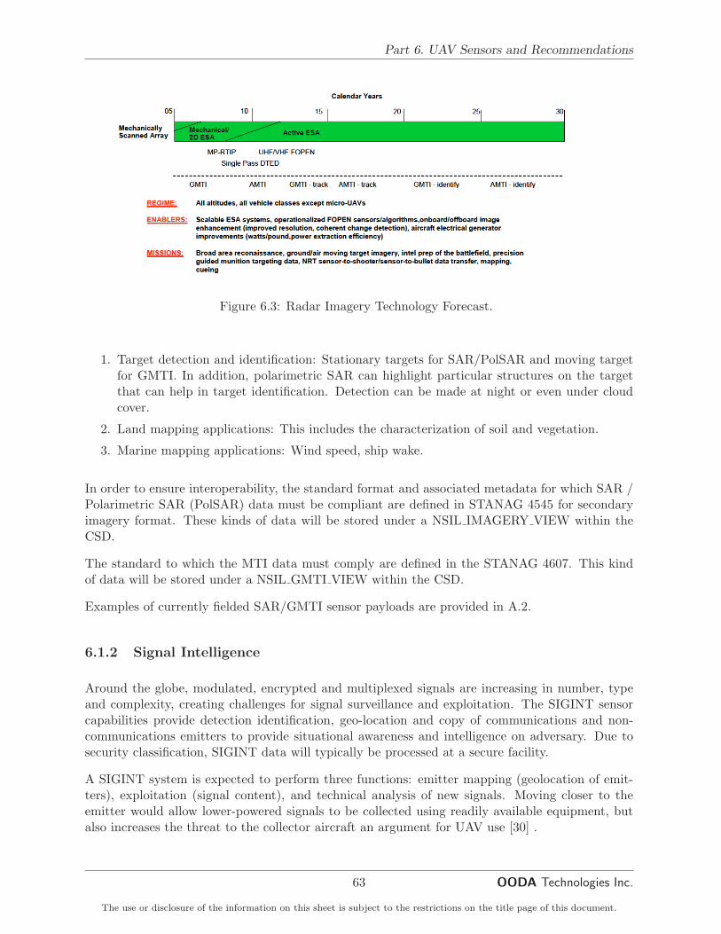
Part 6. UAV Sensors and Recommendations
Figure 6.3: Radar Imagery Technology Forecast.
1. Target detection and identification: Stationary targets for SAR/PolSAR and moving targetfor GMTI. In addition, polarimetric SAR can highlight particular structures on the targetthat can help in target identification. Detection can be made at night or even under cloudcover.
2. Land mapping applications: This includes the characterization of soil and vegetation.
3. Marine mapping applications: Wind speed, ship wake.
In order to ensure interoperability, the standard format and associated metadata for which SAR /Polarimetric SAR (PolSAR) data must be compliant are defined in STANAG 4545 for secondaryimagery format. These kinds of data will be stored under a NSIL IMAGERY VIEW within theCSD.
The standard to which the MTI data must comply are defined in the STANAG 4607. This kindof data will be stored under a NSIL GMTI VIEW within the CSD.
Examples of currently fielded SAR/GMTI sensor payloads are provided in A.2.
6.1.2 Signal Intelligence
Around the globe, modulated, encrypted and multiplexed signals are increasing in number, typeand complexity, creating challenges for signal surveillance and exploitation. The SIGINT sensorcapabilities provide detection identification, geo-location and copy of communications and non-communications emitters to provide situational awareness and intelligence on adversary. Due tosecurity classification, SIGINT data will typically be processed at a secure facility.
A SIGINT system is expected to perform three functions: emitter mapping (geolocation of emit-ters), exploitation (signal content), and technical analysis of new signals. Moving closer to theemitter would allow lower-powered signals to be collected using readily available equipment, butalso increases the threat to the collector aircraft an argument for UAV use [30] .
63
The use or disclosure of the information on this sheet is subject to the restrictions on the title page of this document.
OODA Technologies Inc.

Final Report for RISOMIA Call-up 3
Figure 6.4 (from [31]) depicts the technology forecast for sensors related to signal intelligence.
Figure 6.4: Signal Intelligence Technology Forecast
The information provided by ELINT and ESM data are generally in the form of track data, wherethe emitter and active sensor suite have been mapped to a particular kind of platform using apriori database. This kind of information is usually transmitted and stored in the CSD in theform of Tactical Data Link. It complies to the standard defined in the STANAG 5516 and is storedin the CSD under a NSIL TDL VIEW
Examples of currently fielded SIGINT sensor payloads are provided in A.3.
6.1.3 Automatic Identification System Receiver
The AIS is a broadcast system used on ships and by vessel traffic services for identifying andlocating vessels by electronically exchanging data with other nearby ships, AIS base stations, andsatellites. When satellites are used to detect AIS broadcasts then the term Satellite-AIS is used.
AIS information supplements maritime patrol radar in UAV payload. It is normally used to performmonitoring of the maritime zone and also to cue more advanced EO/IR sensors.
The information content in the AIS messages is very rich. It includes but is not limited to :
1. The vessel’s Maritime Mobile Service Identity;
2. Navigation status;
3. Rate of turn;
4. Speed;
5. Position;
6. Course;
7. True heading;
8. True bearing;
64
The use or disclosure of the information on this sheet is subject to the restrictions on the title page of this document.

Part 6. UAV Sensors and Recommendations
9. Timestamp of the message;
10. IMO ship identification number;
11. Radio call sign;
12. Name of the ship;
13. Type of ship/cargo;
14. Dimensions of ship;
15. Type of positioning system;
16. Draught of ship;
17. Destination;
18. ETA (estimated time of arrival) at destination;
There is currently no STANAG for AIS data. Some XML formats (NIEM, exactEarth, etc.) existbut none has been accepted as the baseline standard for interoperability for a joint operation. Notethat AIS meets the National Marine Electronics Association (NMEA) standard.
Examples of currently fielded SIGINT sensor payloads are provided in A.4.
6.1.4 Maritime Patrol Radar
All Medium Altitude - Long Endurance (MALE) UAV are usually equipped with such type ofMPR [33]. The information provided by a MPR is generally tracks with internal track number. Itdoes not give any identity information. Examples of currently fielded SIGINT sensor payloads areprovided in A.5.
6.1.5 Light Detection and ranging
Light Detection And Ranging (LIDAR) sensors provide high-resolution, 3-dimensional (3D) geospa-tial data. LIDAR data can be used as a stand-alone product, or as an accurate foundation forrectifying and draping high-resolution imagery.
According to [28], LIDAR provides a way to see urban areas in rich 3-D views that give tacticalforces unprecedented awareness in urban environments. LIDAR data is both high-resolution andhigh-accuracy, enabling improved battlefield visualization, mission planning and force protection.LIDAR also supports automated extraction of urban features like buildings and trees-a criticaltechnological improvement for constructing simulation databases rapidly. Typical LIDAR datasets are 1-meter resolution, although higher resolutions have been collected where possible. Thestandard projection is Universal Transverse Mercator, and the standard format for gridded datais GeoTIFF.
There are normally 5 files for every LIDAR data set [28]:
1. First Return Digital Elevation Model (DEM) - 32-bit floating point gridded matrix
65
The use or disclosure of the information on this sheet is subject to the restrictions on the title page of this document.
OODA Technologies Inc.

Final Report for RISOMIA Call-up 3
2. Last Return DEM - 32-bit floating point gridded matrix
3. Intensity Image (int) - 8-bit
4. Bare Earth DEM - 32-bit floating point gridded matrix
5. Merged Intensity-Color Coded Shaded Relief Image (mrg) - 24-bit
In addition, LIDAR maybe used for explosive hazard detection and weather predicting (e.g DopplerLIDAR could provide data such as cloud density and wind speed as well as vertical wind profile).Also, some new multispectral LIDAR are designed to detect and image effluents that are associatedwith chemical and biological warfare agents [33].
Even if there is no standard available for this kind of data, we could expect to be able to storethem in the format compliant to the STANAG 4545 for secondary imagery or very close and arestored under a NSIL IMAGERY VIEW within the CSD.
6.1.6 Laser Radar
The Laser Radar (LADAR) performs three dimensional imaging. It as the capability to lookthrough cover such as trees, foliage and camouflage. LADAR will produce a virtual picture toreliably identify previously hidden targets (tanks or other vehicles). This technology also has thepotential for assisting with explosive hazard detection.
Even if there is no standard available for this kind of data, we could expect to be able to storethem in the format compliant to the STANAG 4545 for secondary imagery or very close and arestored under a NSIL IMAGERY VIEW within the CSD.
6.1.7 Sensors in the context of maritime surveillance operations
In the context of maritime surveillance, some sensors are of particular importance. In addition toEO/IR sensors, that are the eye of the UAV for the ground crew and is not optional, the followingsensors should be prioritized when building a UAV for maritime surveillance :
• AIS receiver : All ship above a certain gross tonnage are equipped with an AIS which makethis sensor a valuable asset in a UAV payload.
• Maritime patrol radar : Can be used to detect smaller ship not equipped with AIS, inall-weather condition, or validate an AIS detection.
• SAR imagery : Can provide all-weather target detection and provide some information onthe detected of object.
• SIGINT Sensor suite : This sensor can provide identity information based on the mea-surement of electronic signatures. Mainly used for military application.
AIS and MPR are usually used to cue the UAV towards a detected vessel so that the EO/IR sensorcan take an image or a video feed of it to provide enhanced situation awareness.
66
The use or disclosure of the information on this sheet is subject to the restrictions on the title page of this document.

Part 6. UAV Sensors and Recommendations
Currently, the U.S. Navys Broad Area Maritime Surveillance (BAMS) sensor suite, includingNorthrop Grummans Multi-Function Active Sensor radar, Raytheons MTS-B with an AIS forship tracking, and an Electronic Support Measures (ESM) system is the largest UAV programdedicated to maritime surveillance [24]. This sensor suite developed as part of it is composed of allthe sensor types identified above which will make the UAV equipped with it the perfect candidatefor maritime surveillance mission.
6.1.8 Sensors in the context of maritime environmental operations
Some other payload can be included in the UAV to gather information about the state of the oceanand the environmental conditions. Many of these sensors produce point-based measurements. Cou-pled with a GPS, these point-based measures can be georeferenced and store for further processingat the ground station using dedicated software. The following list presents the type of environ-mental parameters that can be gathered using different sensors as well as their intermediate andend products.
• Wind Speed/Direction : These parameters are measured using a pitot, which when cou-pled with a GPS measurement provides point-based measurements of wind speed and direc-tion at constant intervals. These points are then usually processed at ground station andincluded in the form of directional vectors as overlay on an image product (see figure 6.5,from http://marine.rutgers.edu/~shann16/page1.html).
• Relative Humidity, Temperature and Pressure : These parameters are measured us-ing digital meteorological sensors (thermometer, hygrometer and barometer), which whencoupled with a GPS measurement provides point-based measurements of wind speed anddirection at constant intervals. These points are usually further processed using dedicatedand/or specialized software. The end products are usually presented as map overlays andcan therefore be included in the NSIF format.
• Ocean /Ice Skin Temperature : Measured by an infrared thermometer or by an Infraredsensor, the end product is usually a heat map in an image format.
• Ocean/Ice Images : These are standard imagery products taken by a digital camera.
• Shortwave Radiation : Measure by an Up and Down-Looking Pyranometer, which whencoupled with a GPS measurement provides point-based measurements, These points areusually further processed using dedicated and/or specialized software. It produces an imageor heat map that display the shortwave radiation intensity.
• Longwave Radiation : Measure by an Up and Down-Looking Pyranometer, which whencoupled with a GPS measurement provides point-based measurements, These points areusually further processed using dedicated and/or specialized software. It produces an imageor heat map that display the longwave radiation intensity.
• Altitude and Surface Waves : These can be measured by a laser altimeter. This kind ofsensor provides georeferenced point-based measurement of the altitude of the sensor relativeto the surface from which the altitude of the surface or the surface waves of the sea are
67
The use or disclosure of the information on this sheet is subject to the restrictions on the title page of this document.
OODA Technologies Inc.

Final Report for RISOMIA Call-up 3
Figure 6.5: Ocean weather image presenting waves heights and wind speed and direction
then derived. These points are usually further processed using dedicated and/or specializedsoftware. It produces a digital elevation model, in the case of altitude, or an image or heatmap that display the waves heights (see figure 6.5).
All these parameters can contribute to the Recognised Environmental Picture which is definedas a complete and seamless depiction of geospatial, oceanographic and meteorological informationdesignated for the planning and conduct of joint operations in a specific area at a specific time andwhich supports the unity of effort across the joint Battlespace [12].
Meteorological data are not defined as a standard product in the CSD and should not be in the nearfuture. As stated in [12], NATO is currently seeking to develop NATO Environmental FunctionalServices. Currently, for distribution of the geospatial information NATO has adopted the servicemodel described by the Open Geospatial Consortium, including Web Map Service, Web FeatureService and Web Coverage Service, as well as Web Map Tile Service. It is expected that in caseof oceanographic and meteorological information the standard services need to be extended withdimension parameters (e.g. time, elevation). For non-geospatial information (e.g. texts, diagrams,multi-media files) general web services, e.g. based on the XML, are to be used [12].
68
The use or disclosure of the information on this sheet is subject to the restrictions on the title page of this document.
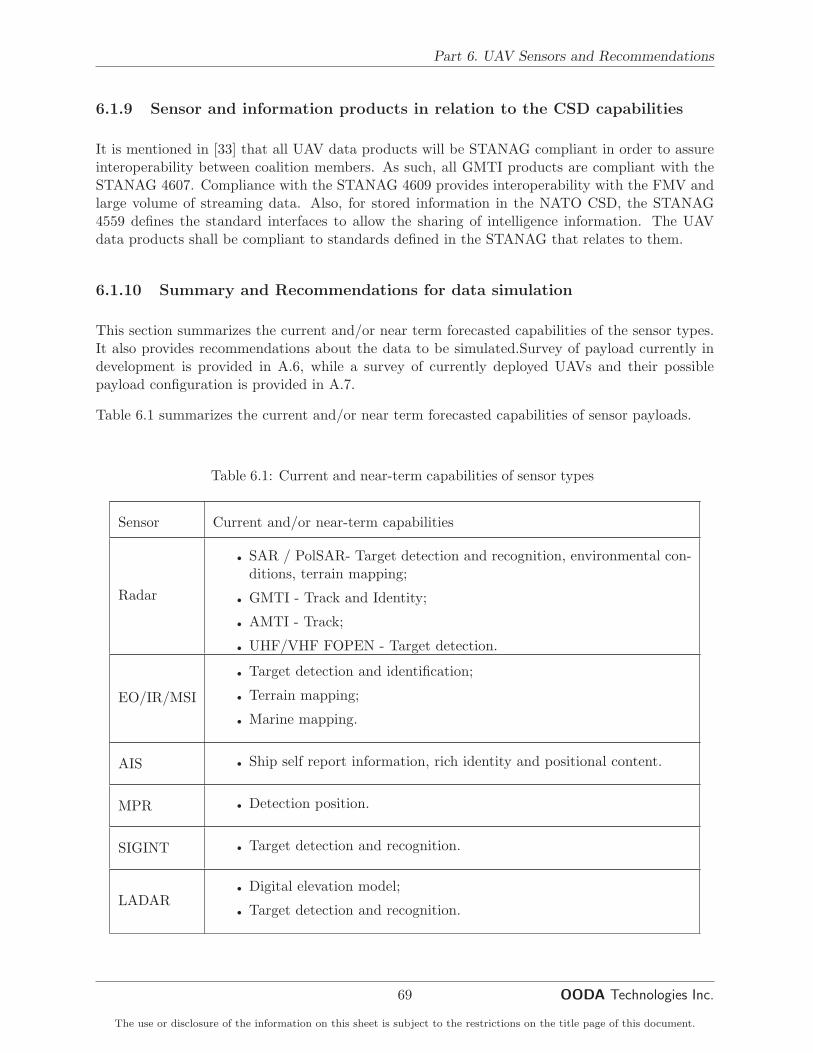
Part 6. UAV Sensors and Recommendations
6.1.9 Sensor and information products in relation to the CSD capabilities
It is mentioned in [33] that all UAV data products will be STANAG compliant in order to assureinteroperability between coalition members. As such, all GMTI products are compliant with theSTANAG 4607. Compliance with the STANAG 4609 provides interoperability with the FMV andlarge volume of streaming data. Also, for stored information in the NATO CSD, the STANAG4559 defines the standard interfaces to allow the sharing of intelligence information. The UAVdata products shall be compliant to standards defined in the STANAG that relates to them.
6.1.10 Summary and Recommendations for data simulation
This section summarizes the current and/or near term forecasted capabilities of the sensor types.It also provides recommendations about the data to be simulated.Survey of payload currently indevelopment is provided in A.6, while a survey of currently deployed UAVs and their possiblepayload configuration is provided in A.7.
Table 6.1 summarizes the current and/or near term forecasted capabilities of sensor payloads.
Table 6.1: Current and near-term capabilities of sensor types
Sensor Current and/or near-term capabilities
Radar
• SAR / PolSAR- Target detection and recognition, environmental con-ditions, terrain mapping;
• GMTI - Track and Identity;
• AMTI - Track;
• UHF/VHF FOPEN - Target detection.
EO/IR/MSI
• Target detection and identification;
• Terrain mapping;
• Marine mapping.
AIS • Ship self report information, rich identity and positional content.
MPR • Detection position.
SIGINT • Target detection and recognition.
LADAR• Digital elevation model;
• Target detection and recognition.
69
The use or disclosure of the information on this sheet is subject to the restrictions on the title page of this document.
OODA Technologies Inc.

Final Report for RISOMIA Call-up 3
HSI
• Target detection and identification;
• Terrain mapping;
• Marine mapping.
Video
• Enhanced situational awareness (example : visual of crew on deck)
• Integrated target designation
• Autonomous operation
• Target search/ID functions
With regards to recommendation on data to simulate we can state the following. First, thecurrently available data is video and metadata, suggesting that still EO/IR imagery should alreadybe available. Also, in the context of maritime ISR, LADAR and HSI are not really useful in thecontext of maritime ISR.
Therefore, considering the sensor and information usefulness in maritime surveillance, probabilityof being part of payload and how relatively easy it is to simulate, ordered in priorities, one shouldsimulate the following :
• AIS receivers;
• Maritime patrol radar;
• EO/IR and SAR / Inverse SAR;
• SIGINT components : ESM principally and IFF to a lesser extent.
Imagery might be difficult to simulate but, based on past experience, image databases alreadyexist and should be available within the DRDCs (e.g Foward Looking Infrared and SAR/InverseSAR).
70
The use or disclosure of the information on this sheet is subject to the restrictions on the title page of this document.

Part 7. Difficulties and Conclusion
Part 7
Difficulties and Conclusion
7.1 Difficulties encountered
Several difficulties were encounter during this Call-up. Most of them were related to incompletedocumentation.
• The installation of the software furnished as GFI, the operations were not always obvious,the documentation was not always accurate and several work arounds had to be found.
• SC2PS does not install correctly under Windows 7 and no error window is ever thrown toprovide the user with a reason of non-working functionalities.
• The CSD and the API documentation was not complete or inexistant which reflected in thetime it took to realize some of the tasks.
• The MTC2 documentation was not available as GFI during the time frame of this call up.As such, it was necessary to devote a certain amount of time to finding and digesting severaltechnical documents and papers, presentations and news articles scattered in the world wideweb.
• The CSD API version 2.0 provided in the lib directory of the CSD is not working properlyfor product creation. No error is thrown at the developer. The CSD API version 2.3, foundin the lib directory of SC2PS solved the problem without code modification.
7.2 Conclusion
This section concludes the final report for Call-up 11 and Call-up 3. Within these Call-ups, severalaspects of the CSD and UAV were investigated in the context of maritime situation awareness.
• A test bed has been developed to send UAV data into a CSD instance and synchronize it
71
The use or disclosure of the information on this sheet is subject to the restrictions on the title page of this document.
OODA Technologies Inc.

Final Report for RISOMIA Call-up 3
with another CSD instance. A slowdown mechanism was putted in place to mimic networkdisturbance by limiting the bandwidth available between CSD instances.
• Investigation has been made to assess the possibility of storing motion imagery data providedby a UAV in the NPR (GPW v2.0). It was determined that the two systems are sufficientlydifferent and that unless major modifications are made to the NPR or post-processing aremade on the UAV data, these are not compatible at least for video imagery.
• AIS data in relation with the CSD was also investigated. AIS decoders were implemented andthe decoded messages were successfully mapped in the NIEM XML data exchange standard.However, some work around had to made to store the data in the CSD as no standard areactually adopted for AIS metadata/data storage and interoperability.
• A comparison of the current GCCS-M with the upcoming MTC2 highlighted their differencesat the architectural and functional levels.
• A survey of current and future UAV sensor payloads was made, which led to recommandationson which data would be best to simulate in the context of maritime surveillance.
72
The use or disclosure of the information on this sheet is subject to the restrictions on the title page of this document.

Bibliography
[1] NATO Standardization Agency. Stanag 5516 tactical data exchange - link 16. Technicalreport, NATO, 2006.
[2] NATO Standardization Agency. Nato ground moving target indicator format (gmtif) stanag4607 implementation guide. Technical report, NATO, 2008.
[3] NATO Standardization Agency. Nato motion imagery (mi) stanag 4609 (edition 3) imple-mentation guide. Technical report, NATO, 2009.
[4] NATO Standardization Agency. Nato standard isr library interface (nsili) edition 3. Technicalreport, NATO, 2010.
[5] NATO Standardization Agency. Nato secondary imagery format (nsif) stanag 4545 (edition2) implementation guide. Technical report, NATO, 2013.
[6] Jean-Pierre Ardouin, Josee Levesque, Vincent Roy, Yves Van Chestein, and Anthony Faust.Demonstration of hyperspectral image exploitation for military applications. In Remote Sens-ing - Applications, pages 493–516. 2012.
[7] Jaroslav Blaha. Information technology standards and standardization. chapter A Standards-based Common Operational Environment, pages 152–167. IGI Global, Hershey, PA, USA,2000.
[8] Deidre Briggs. Nces: Enabling the dod net-centric data and service strategies.1105govinfoevents.com/events/2009/sds09/colbriggspresentation.pdf, 2009. [On-line; accessed November-2013].
[9] Chris Bursk. Independent research of the united states defense information infrastructurecommon operating environment. http://www.reocities.com/cbursk/COEresearch.html,2003. [Online; accessed January-2014].
[10] Ada Information Clearinghouse. Plug and play for the warfighter. http://archive.adaic.com/news/Newsletter/1997/fall/7.htm, 1997. [Online; accessed January-2014].
[11] U.S. Army Information Systems Engineering Command. Automated information systems(ais) design guidance long-haul transmission systems. http://www.fas.org/spp/military/docops/army/lhaul/Lhfinweb.htm, 1998. [Online; accessed November-2013].
[12] NATO Communication and Information Agency. Market survey co-13524-ms - functionalservices for environmental support to operations, July 2012.
73

Final Report for RISOMIA Call-up 3
[13] Keith Debban. Maritime tactical command and control (mtc2) industry day.http://www.defenseinnovationmarketplace.mil/resources/USN%202011%2011%209%
20MTC2%20Industry%20Day.pdf, 2011. [Online; accessed November-2013].
[14] DevTome. Introduction of cloud computing to the united states navy. http://devtome.com/doku.php?id=navy_cloud_computing, 2013. [Online; accessed November-2013].
[15] Gregory Frazier. The dii coe: An enterprise framework. Cross Talk, October 2001.
[16] Flight Global. Watchkeeper uav edges towards uk acceptance. http://www.flightglobal.
com/news/articles/watchkeeper-uav-edges-towards-uk-acceptance-391499/, 2013.[Online; accessed October-2013].
[17] Northrop Grumman. An/zpy-2 multi-platform radar technology insertion program (mp-rtip). http://www.northropgrumman.com/Capabilities/MPRTIP/Pages/default.aspx,2013. [Online; accessed October-2013].
[18] Donald Harder. Moving navy command and control into the future. http://www.public.
navy.mil/spawar/Press/Documents/Publications/1.30.2013_AFCEA[150_PM].pdf,2013. [Online; accessed November-2013].
[19] HomelandSecurity-Technology.com. Sagem completes flight test of pa-troller drone system. http://www.homelandsecurity-technology.com/news/
newssagem-completes-flight-test-of-patroller-drone-system, 2012. [Online;accessed October-2013].
[20] Jerome Hudson. Software agents and the defense information infrastructure: reengineeringthe acquisition process. Technical report, DTIC Document, 1998.
[21] Israel Aerospaces Industries. Iai/malat solutions for the maritime arena. http://www.iai.
co.il/sip_storage/FILES/3/38133.pdf, 2013. [Online; accessed October-2013].
[22] Anthony W. Isenor and Eric Dorion. The use of gccs in the canadian navy and its relationshipto c2iedm. Technical Report DRDC-ATLANTIC-TM-2004-197, DRDC-Atlantic, Dartmouth,February 2005.
[23] Janes. Ausa 2013: Ultraeagle elint system makes its debut. http://www.janes.com/article/28963/ausa-2013-ultraeagle-elint-system-makes-its-debut, 2013. [Online; accessedOctober-2013].
[24] Earth Imaging Journal. Uav market set for 10 years. http://eijournal.com/
uncategorized/uav-market-set-for-10-years, 2011. [Online; accessed October-2013].
[25] US Navy. Exhibit r-2, rdt and e budget item justification: Pb 2013 navy. http://www.dtic.mil/descriptivesum/Y2013/Navy/stamped/0303238N_7_PB_2013.pdf, 2012. [Online; ac-cessed November-2013].
[26] U.S. Navy. Multimode sensor / seeker. http://www.onr.navy.mil/en/Media-Center/
Fact-Sheets/Multi-Mode-Sensor-Seeker.aspx, 2013. [Online; accessed October-2013].
[27] Depertment of Defence. Nces tech guide. https://metadata.ces.mil/dse/ns/ces/
techguide/printable_techguide.doc, 2008. [Online; accessed January-2014].
74
The use or disclosure of the information on this sheet is subject to the restrictions on the title page of this document.

BIBLIOGRAPHY
[28] US Army Corps of Engineers. Lidar data. http://www.agc.army.mil/Media/FactSheets/
FactSheetArticleView/tabid/11913/Article/10229/lidar-data.aspx, 2013. [Online;accessed December-2013].
[29] Office of the Chief Information Officer. Department of defense information enterprise archi-tecture version 1.1. Technical report, Department of Defence, 2009.
[30] Office of the Secretary of Defence. Unmanned aerial vehicles roadmap 2000 - 2025. Technicalreport, Department of Defence, 2001.
[31] Office of the Secretary of Defence. Unmanned aircraft systems roadmap 2005 - 2030. Technicalreport, Department of Defence, 2005.
[32] Margaret Rouse. Infrastructure as a service. http://searchcloudcomputing.techtarget.
com/definition/Infrastructure-as-a-Service-IaaS, 2013. [Online; accessed December-2013].
[33] U.S Army UAS CoE Staff. U.s army roadmap for unmanned aircraft systems 2010 - 2035.Technical report, U.S Army UAS Center of Excellence, 2010.
[34] OODA Technologies. Maritime situational awareness research infrastructure (msari): Re-quirements and high level design. Technical report, Defence Research and Development -Atlantic, March 2012.
[35] Fabrizio Vagni. Survey of hyperspectral and multispectral imaging technologies. Technicalreport, NATO RTO, 2007.
[36] Wikipedia. Data as a service. http://en.wikipedia.org/wiki/Data_as_a_service, 2013.[Online; accessed December-2013].
[37] Wikipedia. Mil-std-6011. http://en.wikipedia.org/wiki/TADIL-A, 2013. [Online; accessedJanuary-2014].
[38] Wikipedia. National information exchange model. http://en.wikipedia.org/wiki/
National_Information_Exchange_Model, 2013. [Online; accessed December-2013].
[39] Wikipedia. Platform as a service. http://en.wikipedia.org/wiki/Platform_as_a_
service, 2013. [Online; accessed December-2013].
[40] Wikipedia. Software as a service. http://en.wikipedia.org/wiki/Software_as_a_
service, 2013. [Online; accessed December-2013].
[41] Wikipedia. Tadil-j. http://en.wikipedia.org/wiki/TADIL-J, 2013. [Online; accessedJanuary-2014].
[42] Wikipedia. Nasa world wind. http://en.wikipedia.org/wiki/NASA_World_Wind, 2014.[Online; accessed March-2014].
[43] PR News Wire. Raytheon’s seavue xmc showcases innovative mar-itime radar solutions. http://www.prnewswire.com/news-releases/
raytheons-seavue-xmc-showcases-innovative-maritime-radar-solutions-222503311.
html, 2013. [Online; accessed October-2013].
75
The use or disclosure of the information on this sheet is subject to the restrictions on the title page of this document.
OODA Technologies Inc.

Final Report for RISOMIA Call-up 3
This page is intentionally left blank.
76
The use or disclosure of the information on this sheet is subject to the restrictions on the title page of this document.

Appendix A
Summary of UAV current sensorpayload in the US Navy
A.1 Example of currently fielded EO/IR payloads
As current UAV payload, the AF Predator and Army Hunter use real-time video systems mountedin turrets. While initial systems were derivatives of commercial products, retrofit with sensorsand designators specific to military applications is underway. The Air Force is integrating theMultispectral Targeting System-A EO/IR laser target designators/illuminators into Predator; inthe same vein, the Army is planning to integrate a designator into Shadow (RQ-7B).
There is also the Global Hawk Integrated Sensor Suite (ISS). The ISS consists of a SAR imagingradar with GMTI mode and an EO/IR sensor that produces still imagery.
In the near future, the Advanced EO/IR Unmanned Aircraft (UA) sensor is a high resolution,highly stabilized EO/IR sensor being developed for Army UA by the Army’s Night Vision Elec-tronic Sensors Directorate. It consists of a multi field-of-view sensor that will provide greaterstandoff ranges and highly stabilized gimbals that allow for an increase in the area of coverage. Itsall digital output is Joint Technical Architecture compliant.
A.2 Example of currently fielded SAR payloads
The following list presents a subset of currently fielded SAR payloads onboard of UAS [31]:
• Global Hawk ISS Radar. Dedicated Global Hawk, SAR capable of spot, search, and GMTImodes; 1-foot resolution.
• LYNX. A tactical radar, deployed in various configurations on both manned and unmannedaircraft, most recently on the Army’s I-GNATs. LYNX has a resolution of 4 inches in thespotlight mode, and provides GMTI and coherent change detection capabilities.
A-1

Final Report for RISOMIA Call-up 3
• TESAR. Tactical Endurance SAR (TESAR) is a strip mapping SAR providing continuous 1foot resolution imagery. TESAR is flown on Predator.
• Tactical UAV radar (TUAVR). A 63-pound SAR/MTI radar for use on Army UA. Provides1 foot resolution imagery in strip and spotlight modes and an integrated GMTI capability.The radar has been demonstrated on Hunter UA.
• MISAR. Developed by EADS, this small, Ka-band radar weighs approximately 10 pounds.It has been demonstrated on the German LUNA UA as well as on U.S. helicopters.
The Multi-Platform Radar Technology Insertion Program (MP-RTIP) should result in a morecapable SAR active electronically steered antenna within this decade. Larger UA, such as GlobalHawk for the Air Force and potentially for the Navy’s BAMS role, are one intended recipientof this technology [31]. The MP-RTIP radar uses active electronically scanned array (AESA)technology and commercial off-the-shelf hardware to deliver long range, very high-resolution SAR,GMTI capabilities and air target tracking. A Northrop Grumman - Raytheon team is developingthe radar for the United States Air Force Electronic Systems Center. MP-RTIP, is currently inthe system development and demonstration phase [17].
A.3 Example of currently fielded SIGINT payloads
An example of SIGINT payload is the Ultra Electronics Tactical Communications Systems Ultra-EAGLE ALR-510 airborne tactical ELINT system. Designed particularly for UAV and smallermanned airborne platforms, the system provides wideband microwave search and intercept with aphased interferometry system providing a direction finding accuracy [23].
A.4 Example of currently fielded AIS payloads
For instance, Sagem’s long-endurance Patroller drone system is equipped with an AIS receiver,enabling the real-time monitoring of maritime traffic over a large zone [19].
The Triton MQ-4C, of the the Navy’s BAMS program is also equipped with an AIS receiver. Someof the Navy’s Small Tactical UAS, such as the RQ-21A Interceptor, are also fitted with an AISreceiver.
A.5 Example of currently fielded MPR payloads
The Multi-Function Active Sensor is an active electronically scanned array radar that providesa 360-degree field of view and is part of the current payload of the MQ-4C Triton has an MPRfunctionality. Also the MB-5B Hunter or the MQ-1C Gray Eagle (upgrade of the General AtomicsPredator) ) are equipped with an MPR.
A-2
The use or disclosure of the information on this sheet is subject to the restrictions on the title page of this document.

Appendix A. Summary of UAV current sensor payload in the US Navy
A.6 Sensor payload in development
This section present some system that are currently in development. Essentially, these systemincorporate improvements or increase in performance of current sensor technologies.
For instance, Sagem (http://www.sagem.com) said the Patroller drone was equipped with a newversion of the Sagem Euroflir 350 gyrostabilized optronic pod, including an HDTV channel, third-generation HD infrared channel and a laser rangefinder; an AIS receiver, enabling the real-timemonitoring of maritime traffic over a large zone; and a beacon for detecting distress signals [19].
The Multimode Sensor/Seeker (MMSS) [26] will deliver a sensor suite for use by future recon-naissance and targeting platforms that integrates eye-safe LADAR, visible and mid-wave infraredimaging sensors with a laser rangefinder / designator. The project will implement AutomaticTarget Recognition algorithms to perform target detection, classification, and identification ofmaritime targets and shore facilities. MMSS is also investigating concepts for its incorporationinto the Multi-Spectral Targeting System-A system.
Raytheon’s SeaVue XMC (eXpanded Mission Capability) radar is a next-generation maritime sit-uational awareness package developed during for the Ocean Surveillance Initiative program spon-sored by the US Navy. SeaVue XMC provides both radar and mission system capabilities, includingautomatically detecting, tracking, and sorting thousands of maritime targets simultaneously andcorrelating those radar tracks with AIS contacts. The system geographically registers radar detec-tions to AIS data and digital nautical chart features for more precise tracking, threat location, andaccurate cross-sensor cueing to the electro-optic system. It is currently operational on the UnitedStates (US) Customs and Border Patrol Dash 8 and the P-3 aircraft [43].
Increased onboard processing will also be a technology for future UAVs. Autonomous operation is acurrent capability-push by the Navy in the Office of Naval Research’s autonomous operation FutureNaval Capability initiative and by the Air Force as part of the Air Force Research Laboratory’sSensorcraft initiative.
A.7 Summary of UAV ant their current payloads
Table A.1 provides an overview of currently fielded UAVs and their possible payload configuration.
Table A.1: Currently deployed UAV and available sensor pay-load
UAV Sensor payload
Predator-A (MQ-1)• Raytheon Multispectral Targeting System (MTS)AN/AAS-52
• Northrop Grumman TESAR Synthetic Aperture Radar
A-3
The use or disclosure of the information on this sheet is subject to the restrictions on the title page of this document.
OODA Technologies Inc.

Final Report for RISOMIA Call-up 3
Predator-B (MQ-9 Reaper)
• Two-Colour DLTV Television
• High Resolution FLIR
• Synthetic Aperture Radar
Triton (MQ-4C)
• 360-degree field of regard (FOR) sensors
• EO/IR video and still imagery
• MTS-B multispectral targeting system
• Multifunction active sensor (MFAS) electronicallysteered array radar (SAR / MPR)
• AIS receiver
• AN/ZLQ-1 ESM system
Global Hawk
• Synthetic Aperture Radar (SAR)
• Moving Target Indicator (MTI)
• Electro-optical, NIIRS 5.5 / 6.5 (WAS/Spot)
• Infrared, NIIRS 5.0 / 6.0 (WAS/Spot)
• Target Coverage, 1900 Spot target per day
Heron TP
• EO/IR/LRF
• SAR
• Maritime Patrol Radar
• ELINT
• COMINT
• AIS receiver
ScanEagle• EO/IR Camera
• SAR
RQ-11 Raven
• Dual-forward and side-look EO camera nose
• Forward and side-look camera-nose
• Thermal IR
A-4
The use or disclosure of the information on this sheet is subject to the restrictions on the title page of this document.

Appendix A. Summary of UAV current sensor payload in the US Navy
Heron 1
• Electro-optical (TV and IR Combi or triple sensorsTV/IR/LD)
• Synthetic Aperture Radar (SAR)
• Maritime Patrol Radar (MPR)
• COMINT and ESM capability
• Communication Relay package
• Integrated ATC package
• AIS receiver
Kahu 2-eb • Can carry a range of sensor packages up to 3 kg
Hawk• 8 mega pixel still camera or full motion video 2x digitalzoom
CamCopter S-100
• Stabilized Daylight/Infrared Gimbal
• Synthetic Aperture Radar
• Light Detection and Ranging
• Multispectral Imaging
• Ground Penetrating Radar
Rheinmetall KZO
• FLIR
• SAR
• ESM
Hermes 900 Maritime Patrol
• Gabianno T-200 MPR and SAR/GMTI
• AIS Receiver
• DCoMPASS EO/IR/Laser
• AES 210 V - ESM/ELINT with IFF Transponder
• Skyfix / Skyjam - COMINT/DF and optional COM-JAM system
Seeker 400 (Denel Dynamics)
• Zeiss LEO III (electro-optic (EO), infra-red (IR))
• Electronic Surveillance Payload (ESP)
• ELINT
• SAR
• MPR
A-5
The use or disclosure of the information on this sheet is subject to the restrictions on the title page of this document.
OODA Technologies Inc.

Final Report for RISOMIA Call-up 3
An other UAS in service is the Watchkeeper. It is an UK UAV, carrying an electro-optical/infraredsensor and synthetic aperture radar/ground moving target indication payload, the Watchkeeperair vehicle is an evolution of the Hermes 450 airframe [16].
One of the latest UAS released by Lockheed Martin Corporation is the stealth Q-170 Sentinel.An electro-optic and infra-red sensors are incorporated in the upper surface of the RQ-170 wings.The RQ-170 Sentinel is fitted with an active electronically scanned array radar, synthetic apertureradar and signal intelligence in its belly fairings.
A-6
The use or disclosure of the information on this sheet is subject to the restrictions on the title page of this document.