Embed Size (px)
DESCRIPTION
UATE
Citation preview
7/17/2019 Uaet Industrial Noise Series Viii Absorptive Silencer Design
http://slidepdf.com/reader/full/uaet-industrial-noise-series-viii-absorptive-silencer-design 1/9
INDUSTRIAL NOISE SERIES
PART VIII: ABSORPTIVESILENCER DESIGN
TABLE OF CONTENTS
Introduction 2
Silencer Performance 4
Flow Resistance and Resistivity 7
Flow Velocity 7
Baffle Attenuation Example 7Silencer Design 8
Performance Criteria 9
Elden F. Ray
June 10, 2013

7/17/2019 Uaet Industrial Noise Series Viii Absorptive Silencer Design
http://slidepdf.com/reader/full/uaet-industrial-noise-series-viii-absorptive-silencer-design 2/9
INDUSTRIAL NOISE SERIEPART VIII: ABSORPTIVE SILENCER DESIG
INTRODUCTION
The basics of absorptive silencer design and the fundamental approach in design of parallel baffle
silencers is presented. The reduction of sound energy using absorptive materials is achieved by
transferring the acoustical pressure (wave motion) into material motion. This mechanical motion is
converted into heat (energy loss) by material damping and friction. The more effective the sound wave
penetrates the material the more effective the attenuation. Each baffle assembly consists of
“compartments” and the basic theory is each compartment is locally reacting where the acoustic sound
wave “pumps in and out” though the material as well as through the perforated facing sheet or pack
material retainer. The perforation pattern adds damping and frictional losses to the aero-acoustic wave
oscillating through the holes; the smaller the holes and more perforations, the more attenuation. The
packing consists of absorptive material that is principally fibrous materials or open cell foams that allow
the wave energy to penetrate, induce material motion, and be attenuated.
The wavelength of sound is a major factor in sound reduction as well since the absorptive material only
starts to become effective when its thickness is at least one-tenth the wavelength so obviously, very low
frequencies are not well attenuated. The effective depth of a baffle is one-half its thickness as acoustic
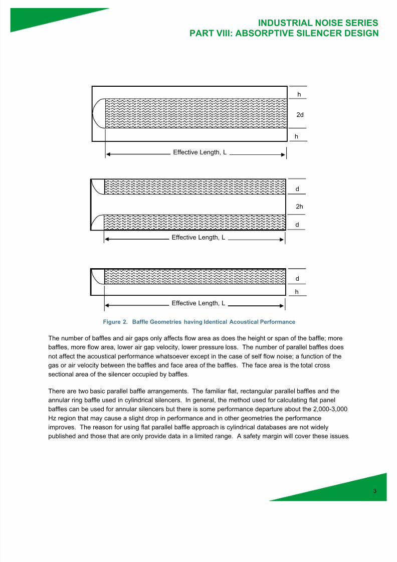
energy is propagating into the baffle from both sides. Baffle geometry is described in the following figure
and the descriptors vary between resources. Silencers were developed based on this geometry and the
corresponding open area ratio (OAR) of the baffles in the silencer duct. The open area is the area
available for gas or air flow through the silencer.
Figure 1. Baffle Geometry
Silencer - Baffle OAR% = 100 x 2h/(2h + 2d) = 100 x h/(h + d)
Full air gap = 2h, Baffle thickness = 2d
Note that half gaps and half baffle thickness are h and d respectively and performance is based on these
parameters permitting the use of half baffles and half gaps in silencer applications. Each configuration in
the following series of figures has the identical acoustical performance and OAR to that of Figure 1
assuming the dimensions d, h and L are identical.
d
2h
2d
Effective Length, L
7/17/2019 Uaet Industrial Noise Series Viii Absorptive Silencer Design
http://slidepdf.com/reader/full/uaet-industrial-noise-series-viii-absorptive-silencer-design 3/9
INDUSTRIAL NOISE SERIEPART VIII: ABSORPTIVE SILENCER DESIG
Figure 2. Baffle Geometries having Identical Acoustical Performance
The number of baffles and air gaps only affects flow area as does the height or span of the baffle; more
baffles, more flow area, lower air gap velocity, lower pressure loss. The number of parallel baffles does
not affect the acoustical performance whatsoever except in the case of self flow noise; a function of the
gas or air velocity between the baffles and face area of the baffles. The face area is the total cross
sectional area of the silencer occupied by baffles.
There are two basic parallel baffle arrangements. The familiar flat, rectangular parallel baffles and theannular ring baffle used in cylindrical silencers. In general, the method used for calculating flat panel
baffles can be used for annular silencers but there is some performance departure about the 2,000-3,000
Hz region that may cause a slight drop in performance and in other geometries the performance
improves. The reason for using flat parallel baffle approach is cylindrical databases are not widely
published and those that are only provide data in a limited range. A safety margin will cover these issues.
d
h
Effective Length, L
d
2h
d
Effective Length, L
h
2d
Effective Length, L
h

7/17/2019 Uaet Industrial Noise Series Viii Absorptive Silencer Design
http://slidepdf.com/reader/full/uaet-industrial-noise-series-viii-absorptive-silencer-design 4/9
INDUSTRIAL NOISE SERIEPART VIII: ABSORPTIVE SILENCER DESIG
Key parameters that are used for baffle design are the dimensions cited above, the airflow resistivity of
the pack material (rayls/m), the airflow resistance (rayls) of any thin layer retainer materials. Moresophisticated analyses include the thickness and areal density of the perforated face sheet, perforation
diameter and oar, the density of the pack material, and its material properties. These latter parameters
are frequently missing from standard “lookup curves.”
SILENCER PERFORMANCE
The challenge in baffle design is determining the attenuation in a grazing flow environment; that is, the
sound travels parallel to the surface (grazing) thus interaction of the sound wave with the baffle is not
optimal at all. The direction of flow with respect to the direction of the sound wave also affects
performance in that for an identical baffle and sound energy, the performance will be different for a
positive traveling wave versus a negative traveling wave. The following figure illustrates the flow regimes;the curves represent the sound energy.
Figure 3a. Positive Flow Case – Sound and Flow are Traveling Downstream; This Is Commonly Known
as Exhaust or Supply Flow.
Figure 3b. Negative Flow Case – Sound Travels Upstream and Flow Travels Downstream; This Is Commonly
Known as Inlet or Return Flow.
Calculating silencer performance was not developed when ventilation equipment started being installed in
buildings and the only method was to build and test silencers. Later, the HVAC1 industry developed
standardized testing protocols to measure silencer performance. The national standard is ASTM E 477,Standard Test Method for Measuring Acoustical and Airflow Performance of Duct Liner Materials and
Prefabricated Silencers. The ISO standard is, ISO 7235 Acoustics – Laboratory measurement
procedures for ducted silencers and air-terminal units – Insertion loss, flow noise and total pressure loss.
Also, there is a standard for measuring silencer performance in-situ or for very large silencers that cannot
be measured in a laboratory; it is ISO 11820 Acoustics – Measurements on silencers in situ. It provides
guidelines for measuring both insertion loss (IL) and transmission loss (TL).
1 Heating, Ventilation and Air Conditioning (HVAC)
Air Flow
Air Flow

7/17/2019 Uaet Industrial Noise Series Viii Absorptive Silencer Design
http://slidepdf.com/reader/full/uaet-industrial-noise-series-viii-absorptive-silencer-design 5/9
INDUSTRIAL NOISE SERIEPART VIII: ABSORPTIVE SILENCER DESIG
Although computational capabilities now exist, the complexity of the silencer required a significant amount
of analysis that naturally had some uncertainty regarding performance thus most all HVAC silencermanufacturers just tested their products and cataloged them for easy selection. With over 50 years of
testing, databases (performance curves based on OAR) have been developed. Figure 4 (Fig. 10.20 from
Beranek and Ver)2 shows normalized attenuation performance for a 66% open area silencer based on
four acoustical materials under no-flow (static) conditions. The four materials have normalized flow
resistances of 1, 2, 5 and 10.
Figure 4. Normalized Attenuation versus Frequency for Parallel Baffles
The abscissa is the full air gap (2h) divided by the wavelength (c/f). The ordinate shows the attenuation
rate, Lh in decibels per half gap (h); the baffle attenuation is Lh multiplied by (L/h). Some resources show
the attenuation rate per full gap (2h) so the ordinate values would be half that shown; so be careful when
comparing databases. And also note, terminology and symbols may vary between resources.
Parallel baffle performance is contingent upon the open area of the baffle arrangement (OAR) and a
unique performance curve for each open area is required; thus, a family of curves covering 25%, 33%,
40%, 50%, and 66% are common in any design and analysis library and each family of curves will include
performances based on the pack material’s flow resistivity. If a baffle arrangement has some other OAR
then the result is obtained by interpolation.
2 A.G. Galaitsis and I.L. Ver, “Passive Silencers and Lined Ducts,” Ch 10 in Noise and Vibration Control Engineering Principles and
Applications, edited by Beranek, L.L. & Ver, I.L. (John Wiley & Sons Inc. NY 1992)

7/17/2019 Uaet Industrial Noise Series Viii Absorptive Silencer Design
http://slidepdf.com/reader/full/uaet-industrial-noise-series-viii-absorptive-silencer-design 6/9
INDUSTRIAL NOISE SERIEPART VIII: ABSORPTIVE SILENCER DESIG
What is not shown in these normalized graphs is the perforated face sheet of the baffle. The open area
of the perforated face sheet also affects performance; particularly above 1,000 Hz. Most all HVACsilencers use 40% open area thus it is seldom an issue in terms of application but for industrial
applications where low percentage perforated sheeting may be used it does become important. In
general, for typical engine applications 23% is acceptable but in the case of turbine exhausts that have
high frequency content, then 32-35% should be considered. For turbine inlets, high-speed fans, and any
devices that have significant tones above 1,000 Hz, use 40% as a minimum. The open area ratio (OAR)
in percent of perforated sheeting may be calculated by,
Square perforation pattern: P% = 78.5(d/b) 2 (1)
Hex perforation pattern: P% = 90.7(d/b) 2 (2)
Where d is the diameter of the hole and b is the center-to-center spacing of the holes.
FLOW RESISTANCE AND RESISTIVITY
Flow resistance or resistivity is a measure of the material’s resistance to penetration by a sound wave;
the lower the number the easier it is for penetration and better attenuation. Very low flow resistivity is
good for high frequencies and very high flow resistivity is good for low frequencies so there are trade-offs.
ASTM C 522-(year), Standard Test Method for Airflow Resistance of Acoustical Materials is the method
used for performing the measurements. Very thin materials such as fill retainers (screens, cloth and
needle-mats) are measured for their total resistance in rayls and thicker packing materials are measured
for their flow resistivity in rayls/meter. The rayl in this application is an aerodynamic measure of thepressure differential across the material at a known volumetric air velocity. Although not a true acoustical
measurement, it is used for rating the packing material. Testing occurs in a duct with a known cross area
so the parameters for rayls/m are composed of the following units, Pa!s/m2 but Pa is N/m
2 so you may
encounter, N!s/m4.
In Figure 4 there are several curves showing flow resistivity. Note that the peak attenuation occurs where
" is near unity when the air gap (2h) is equal to a wavelength. The curves shown on these types of
figures are the normalized flow resistance of the material and dependent upon the thickness d. By
selecting a particular or desired performance curve (R in Figure 4) and knowing the baffle thickness (d)
the flow resistivity (Rl) of the needed material is then determined by employing the following equation,
R = Rl d/#c dimensionless (3)
where #c is the acoustical impedance of the air (415 rayls) or that of the gas. The units of Rl are
rayls/meter or rayls/inch. It is very important to note that the flow resistance will change with the
operating temperature (T) because of the change in the gas or air viscosity. It may be scaled by,
R(T) = R0(T/T0)1.2
dimensionless (4)

7/17/2019 Uaet Industrial Noise Series Viii Absorptive Silencer Design
http://slidepdf.com/reader/full/uaet-industrial-noise-series-viii-absorptive-silencer-design 7/9
INDUSTRIAL NOISE SERIEPART VIII: ABSORPTIVE SILENCER DESIG
R0 = Rld/#0c0 dimensionless (5)
T is the absolute temperature in Kelvin (273° + °C) and Equation (5) represents the measured laboratory
flow resistance at ambient or laboratory temperature, T0.
FLOW VELOCITY
The flow through baffles also affects the attenuation and longevity of the packing:
! The flow velocity in any application should never exceed Mach 0.3 (0.3 x speed of sound) because
the gas or air will begin to compress changing its properties.
! The Mach number is simply the velocity of the gas/speed of sound (v/c)
! The velocity between the baffles produces self noise that can limit the attenuation of a silencer thus
the velocity should not exceed Mach 0.1 as a general rule.
! The flow affects the sound energy interaction with the baffle by either making the acoustic interaction
either shorter or longer based on the velocity and direction of noise relative to the flow. Downstream
and upstream flow cases are shown in Figure 3. Flow is either positive or negative and is important
in analyzing performance.
! If calculating baffle performance, by using published curves (at no flow), the attenuation rate is
adjusted by (Bies & Hansen, Eq. (9.134)3,
DM = D0[1 – 1.5M + M2
] (6)
Where, D0 is the attenuation rate (without flow) and -0.3 < M < 0.3 where M is the Mach number of
the velocity between the baffles. Be sure to use the correct sign (+/-) of the Mach number depending
on the flow regime (Figure 3). Some resources use different approaches for adjusting for self noise
but this is most conservative and easy to use.
BAFFLE ATTENUATION EXAMPLE
An example calculation of a silencer is demonstrated using the six middle bands. The silencer baffle is
200 mm thick (2d) separated by 400 mm air gap (2h) (66% OAR) that is 1200 mm long. The air
temperature is 20° C with a positive velocity of 30 m/s through the baffles. The packing material of choice
has an airflow resistivity, Rl = 20,000 rayls/m; this results in a normalized value, R = 4.82 for d = 100 mm
(see Eq. 8.4). The “5” curve in Figure 4 is used. The results are given in the following table as explained
below:
3 Bies and Hansen, Engineering Noise Control, Theory and Practice, 4
th edition, © David A. Bies and Colin H. Hanson, 2009
7/17/2019 Uaet Industrial Noise Series Viii Absorptive Silencer Design
http://slidepdf.com/reader/full/uaet-industrial-noise-series-viii-absorptive-silencer-design 8/9
INDUSTRIAL NOISE SERIEPART VIII: ABSORPTIVE SILENCER DESIG
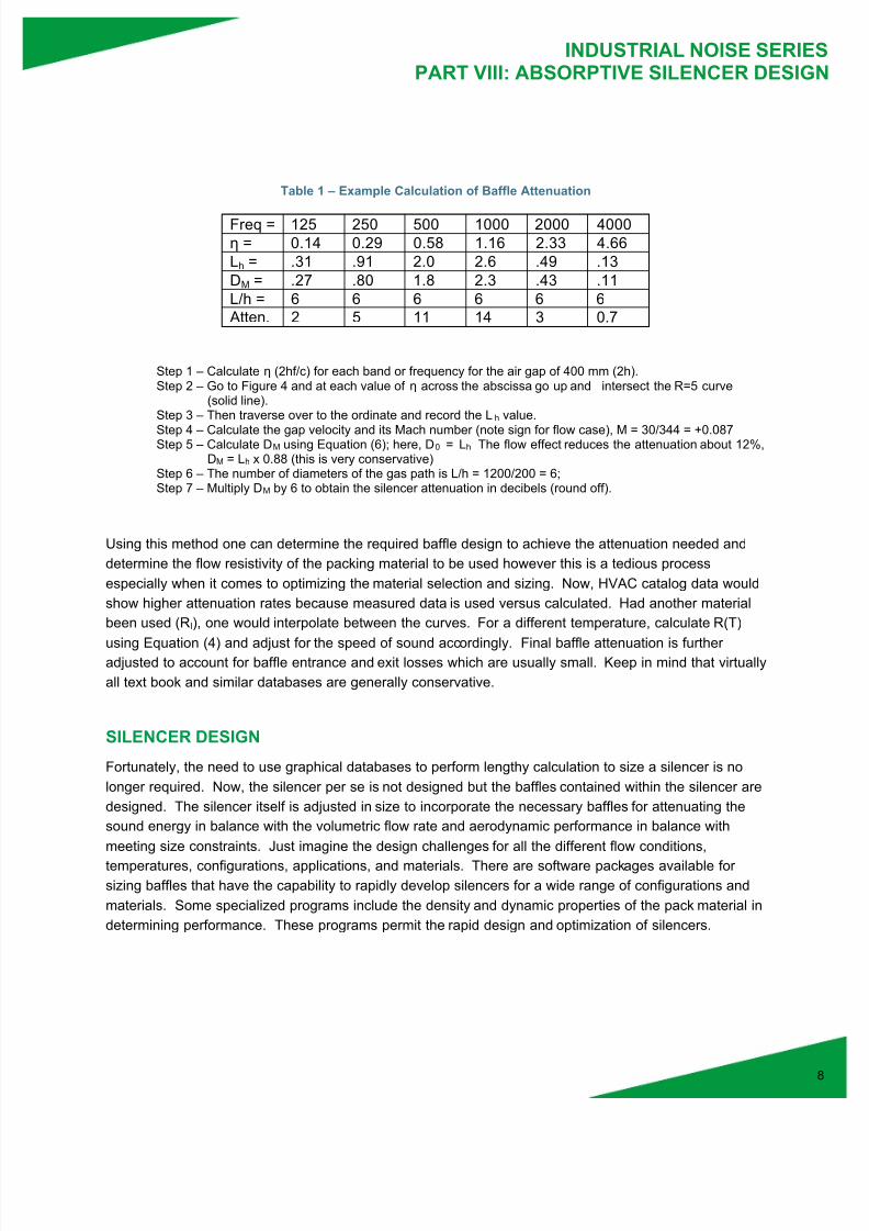
Table 1 – Example Calculation of Baffle Attenuation
Freq = 125 250 500 1000 2000 4000
" = 0.14 0.29 0.58 1.16 2.33 4.66
Lh = .31 .91 2.0 2.6 .49 .13
DM = .27 .80 1.8 2.3 .43 .11
L/h = 6 6 6 6 6 6
Atten. 2 5 11 14 3 0.7
Step 1 – Calculate " (2hf/c) for each band or frequency for the air gap of 400 mm (2h).Step 2 – Go to Figure 4 and at each value of " across the abscissa go up and intersect the R=5 curve
(solid line).Step 3 – Then traverse over to the ordinate and record the Lh value.
Step 4 – Calculate the gap velocity and its Mach number (note sign for flow case), M = 30/344 = +0.087Step 5 – Calculate DM using Equation (6); here, D0 = Lh The flow effect reduces the attenuation about 12%,
DM = Lh x 0.88 (this is very conservative)Step 6 – The number of diameters of the gas path is L/h = 1200/200 = 6;Step 7 – Multiply DM by 6 to obtain the silencer attenuation in decibels (round off).
Using this method one can determine the required baffle design to achieve the attenuation needed and
determine the flow resistivity of the packing material to be used however this is a tedious process
especially when it comes to optimizing the material selection and sizing. Now, HVAC catalog data would
show higher attenuation rates because measured data is used versus calculated. Had another material
been used (Rl), one would interpolate between the curves. For a different temperature, calculate R(T)
using Equation (4) and adjust for the speed of sound accordingly. Final baffle attenuation is furtheradjusted to account for baffle entrance and exit losses which are usually small. Keep in mind that virtually
all text book and similar databases are generally conservative.
SILENCER DESIGN
Fortunately, the need to use graphical databases to perform lengthy calculation to size a silencer is no
longer required. Now, the silencer per se is not designed but the baffles contained within the silencer are
designed. The silencer itself is adjusted in size to incorporate the necessary baffles for attenuating the
sound energy in balance with the volumetric flow rate and aerodynamic performance in balance with
meeting size constraints. Just imagine the design challenges for all the different flow conditions,
temperatures, configurations, applications, and materials. There are software packages available for
sizing baffles that have the capability to rapidly develop silencers for a wide range of configurations and
materials. Some specialized programs include the density and dynamic properties of the pack material in
determining performance. These programs permit the rapid design and optimization of silencers.

7/17/2019 Uaet Industrial Noise Series Viii Absorptive Silencer Design
http://slidepdf.com/reader/full/uaet-industrial-noise-series-viii-absorptive-silencer-design 9/9
INDUSTRIAL NOISE SERIEPART VIII: ABSORPTIVE SILENCER DESIG
888.300.4272
About Universal AET
Universal AET delivers on one simple yet powerful promise – to provide the highest quality,complete air management solutions. With more than a half-century of industrial and powergeneration experience, we engineer solutions to our customers’ unique needs and back them witunparalleled support, across the entire energy generation lifecycle. Your comprehensive single-sourced solution not only meets environmental, regulatory and operational requirements, but alsohelps you reduce costs, improve the efficiency of your equipment and eliminate safety andcompliance risk. We put our expertise to work solving problems for your specific needs.The result: Your world. Clean. Quiet. Safe.
PERFORMANCE CRITERIA
It is critical to clearly state the requirements of the silencer to be supplied and understand what is being
specified and how it will be measured for compliance. The following information should be provided as a
minimum:
a. Acoustical criterion or criteria.
b. Flow rate, operating temperature and pressure loss limits.
c. Machine data and operating conditions.
d. Machine acoustical data – must be frequency based.
e. Connection data, orientation, and size limits including weight.
f. All specifications and standards related to the performance requirements.
g. All specifications and standards related to measurements.