Embed Size (px)
Citation preview

U18LCAU7L2 VEHICLE MAINTENANCE
AND RECONDITIONING LAB
LAB MANUAL
B.Tech IV Year – 7th semester
DEPARTMENT OF AUTOMOBILE ENGINEERING BHARATH INSTITUTE OF HIGHER EDUCATION AND
RESEARCH
173, AGARAM MAIN ROAD, SELAIYUR,
CHENNAI - 600073

U18LCAU7L2 VEHICLE MAINTENANCE AND RECONDITIONING
LAB
0 0 2 1
LIST OF EXPERIMENTS
1. Study and layout of an automobile repair, service and maintenance shop. 2. Study and preparation of different statements/records required for the repair and maintenance
works. 3. Cylinder reboring – checking the cylinder bore, Setting the tool and reboring. 4. Valve grinding, valve lapping - Setting the valve angle, grinding and lapping and checking for
valve leakage 5. Calibration of fuel injection pump 6. Minor and major tune up of gasoline and diesel engines. 7. Study and checking of wheel alignment - testing of camber, caster. 8. Testing kingpin inclination, toe-in and toe-out 9. Brake adjustment and Brake bleeding. 10. Simple tinkering, soldering works of body panels, study of door lock and window glass rising
mechanisms. 11. Battery testing and maintenance. 12. Practice the following:
I. Adjustment of pedal play in clutch, brake, hand brake lever and steering wheel play II. Air bleeding from hydraulic brakes, air bleeding of diesel fuel system
III. Wheel bearings tightening and adjustment IV. Adjustment of head lights beam V. Removal and fitting of tyre and tube

Wheels
and Tyres
Repairs
Transmission
Repairs
Body
Repairs
Main
Replacements
Supervisor Cabin Waiting Room
Air
Supply
Lubrication Petrol
Supply
Diesel
Supply
Painting
Section
Tinkering
Section
Inspection
Section
Electrical Vehicle Testing Stores
Repair
Vehicles
For display
Vehicles
awaiting
services
Security
Gate
Way for
vehicles
Engine Repair
Section
Washing
Ramp
Time
Office
Security
Gate
Way for
vehicles
ENTRY EXIT
Fig 1.1 Layout of Automobile Service Station
Manager Spares Show Room and
Cabin Shop Vehicle Sales
Cabin
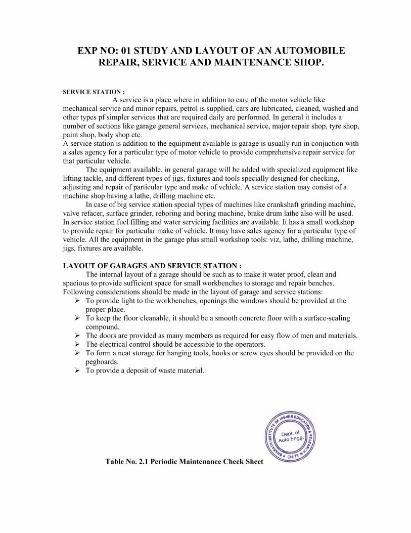
EXP NO: 01 STUDY AND LAYOUT OF AN AUTOMOBILE
REPAIR, SERVICE AND MAINTENANCE SHOP.
SERVICE STATION :
A service is a place where in addition to care of the motor vehicle like
mechanical service and minor repairs, petrol is supplied, cars are lubricated, cleaned, washed and
other types pf simpler services that are required daily are performed. In general it includes a
number of sections like garage general services, mechanical service, major repair shop, tyre shop,
paint shop, body shop etc.
A service station is addition to the equipment available is garage is usually run in conjuction with
a sales agency for a particular type of motor vehicle to provide comprehensive repair service for
that particular vehicle.
The equipment available, in general garage will be added with specialized equipment like
lifting tackle, and different types of jigs, fixtures and tools specially designed for checking,
adjusting and repair of particular type and make of vehicle. A service station may consist of a
machine shop having a lathe, drilling machine etc.
In case of big service station special types of machines like crankshaft grinding machine,
valve refacer, surface grinder, reboring and boring machine, brake drum lathe also will be used.
In service station fuel filling and water servicing facilities are available. It has a small workshop
to provide repair for particular make of vehicle. It may have sales agency for a particular type of
vehicle. All the equipment in the garage plus small workshop tools: viz, lathe, drilling machine,
jigs, fixtures are available.
LAYOUT OF GARAGES AND SERVICE STATION :
The internal layout of a garage should be such as to make it water proof, clean and
spacious to provide sufficient space for small workbenches to storage and repair benches.
Following considerations should be made in the layout of garage and service stations:
To provide light to the workbenches, openings the windows should be provided at the
proper place.
To keep the floor cleanable, it should be a smooth concrete floor with a surface-scaling
compound.
The doors are provided as many members as required for easy flow of men and materials.
The electrical control should be accessible to the operators.
To form a neat storage for hanging tools, hooks or screw eyes should be provided on the
pegboards.
To provide a deposit of waste material.
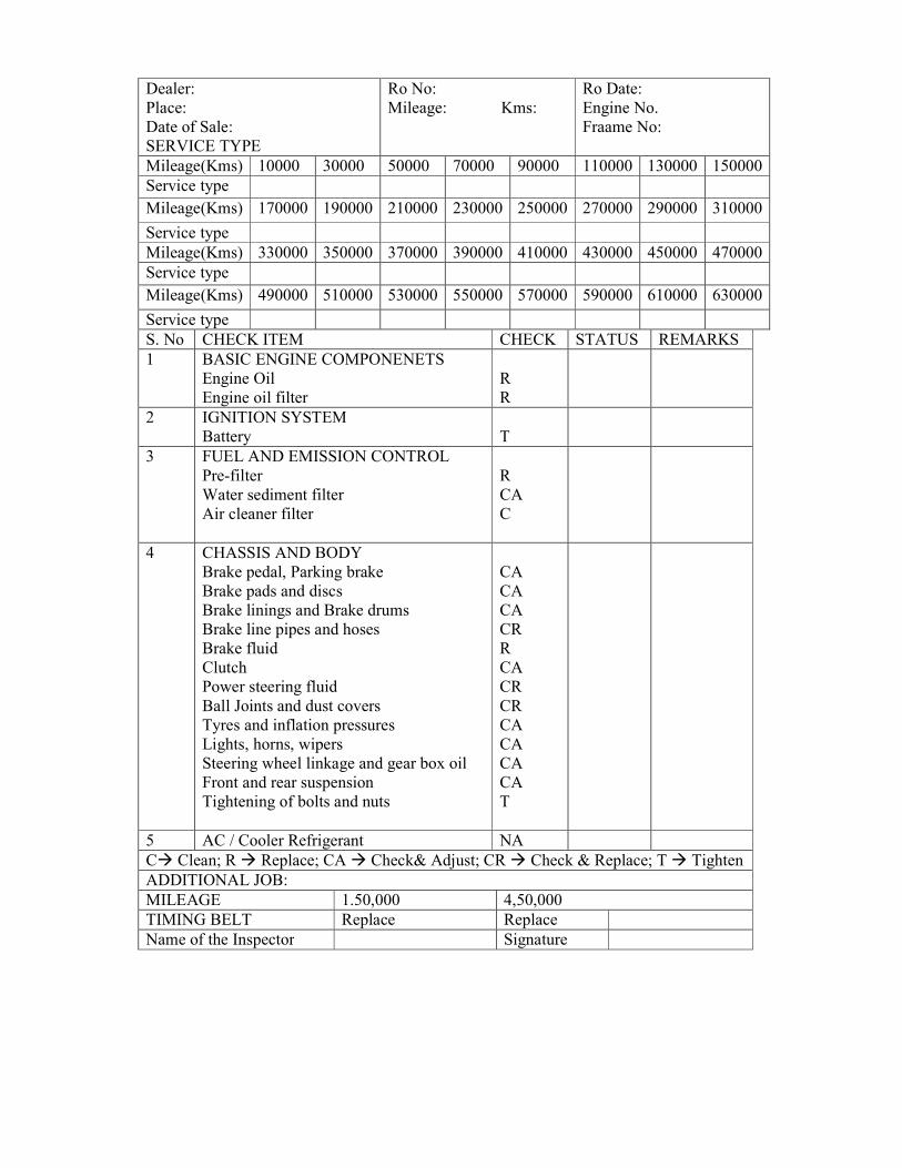
Table No. 2.1 Periodic Maintenance Check Sheet
Dealer:
Place:
Date of Sale:
SERVICE TYPE
Ro No:
Mileage: Kms:
Ro Date:
Engine No.
Fraame No:
Mileage(Kms) 10000 30000 50000 70000 90000 110000 130000 150000
Service type
Mileage(Kms) 170000 190000 210000 230000 250000 270000 290000 310000
Service type
Mileage(Kms) 330000 350000 370000 390000 410000 430000 450000 470000
Service type
Mileage(Kms) 490000 510000 530000 550000 570000 590000 610000 630000
Service type
S. No CHECK ITEM CHECK STATUS REMARKS
1 BASIC ENGINE COMPONENETS
Engine Oil
Engine oil filter
R
R
2 IGNITION SYSTEM
Battery
T
3 FUEL AND EMISSION CONTROL
Pre-filter
Water sediment filter
Air cleaner filter
R
CA
C
4
CHASSIS AND BODY
Brake pedal, Parking brake
Brake pads and discs
Brake linings and Brake drums
Brake line pipes and hoses
Brake fluid
Clutch
Power steering fluid
Ball Joints and dust covers
Tyres and inflation pressures
Lights, horns, wipers
Steering wheel linkage and gear box oil
Front and rear suspension
Tightening of bolts and nuts
CA
CA
CA
CR
R
CA
CR
CR
CA
CA
CA
CA
T
5 AC / Cooler Refrigerant NA
C Clean; R Replace; CA Check& Adjust; CR Check & Replace; T Tighten
ADDITIONAL JOB:
MILEAGE 1.50,000 4,50,000
TIMING BELT Replace Replace
Name of the Inspector Signature

EXP NO: 02 STUDY AND PREPARATION OF DIFFERENT
STATEMENTS AND RECORDS REQUIRED FOR THE
REPAIR AND MAINTENANCE SHOP.
AIM :
To prepare and study the different statements and records required for the repair and
maintenance shop.
TYPES OF RECORDS :
1) Periodic maintenance check sheet.
2) Maintenance schedule sheet.
3) Trip sheet
4) Log book etc.
DESCRIPTION :
Periodic maintenance check sheet
The periodic maintenance check sheet is used to record the inspection status made
during the maintenance check operation. It contains various details such as the dealer name,
place, date of sale, manufacturers name, mileage, frame number, chassis number etc. the mileage
and service type are indicated in the various cells of the check sheet. The check sheet also
contains the check item name, status and remarks.
The check items include the following:
Basic engine components.
Engine oil
Engine oil filter
Ignition system
Battery
Fuel and Emission Control
Pre- Filter
Water sediment filter
Air cleaner filter
Chassis and Body
Brake pedal, parking brake
Brake pads and discs
Brake linings & brake drums
Clutch
Power steering fluid
Ball joints and dust covers
Tyres and inflation pressures
Lights, horns, wipers
Steering wheel linkage & gear box oil etc.
The status and remarks for all the items mentioned above are indicated on the check sheet
during the maintenance operation.
Vehicle Reg No: Job No :
Chassis No : Date :
Table 2.2 Road Test Report
S.No Parameter to check Before work After work
1 Front side abnormal noise
2 Rear side abnormal noise
3 Front/rear suspension noise
4 Steering noise

5 Brake caliper noise
6 Misfiring / starting
7 Hunting problems / Stopping problems
8 Underbody noise
9 Abnormal noise from doors / glasses and body
10 Overheating of engine on AC and Non AC
operation
11 Brakes poor / Weak line effective / noisy
12 Wheel bearings noisy
13 Drive shaft noise / vibration
14 Vehicle pulling to one side
15 Poor pick up of vehicle (with AAAC and
without AC)
Table 2.3 TRIP SHEET
Name and Address of the Agency
REPORT TO
Mr. / Mrs. ------------------------------------------------
-------------------------------------------------------------
----------------------------------
Engaged by Arranged by --------------------- No. --------------- Date: ------------------
Vehicle Number ------------------------------- Driver Name ------------------------------------
Closing Time -----------------
Starting Time -----------------
TOTAL Time -----------------
Signature of the Customer
Hire Charges
Charge Per km
Driver Batta
Excess Hours
Excess Kms
Service Tax
Permit Charges
Rupees
Paise
Advance Rs. --------------- TOTAL
Driver’s Signature
For Agency
ROAD TEST REPORT:
1. The road test inspector or the machine makes the road test report after the completion
of the maintenance operation.
2. This report contains the vehicle reg number, chassis number, job no, date of test etc.
3. The parameters to be checked include the following:
Front side and rear side abnormal noise.
Steering and brake caliper noise.
Ilunting, misfiring, sudden stoppage of vehicle.
Brake condition.
Wheel and bearing check.
Pick up of the vehicle.
Mileage of the vehicle etc.

The road test report gives a fare idea of the condition of the vehicle before and after
the maintenance operation.
TRIP SHEET :
The trip sheet gives the entire details of the vehicle before and after a trip. The
starting km and ending km, time of start and closing of the journey time and the charges
per km and also the overall cost of trip is described in the trip sheet.
LOGBOOK :
The logbook of a vehicle gives the details of the vehicle, which will be useful not only
for the owner of the vehicle but also to the mechanic who might take the job of vehicle
maintenance latter.
The logbook contains the following details:
Distance covered
Fuel consumption
Average fuel consumption
Best and worst mileage
Total maintenance cost
Running costs
Faults in the vehicle
Likes and dislikes
Date of the previous maintenance report
CONCLUSION :
The different statements and records required for the repair and maintenance works
were prepared and the uses of records were studied.

EXP NO: 03 CYLINDER REBORING-CHECKING THE
CYLINDER BORE, SETTING THE TOOLS AND REBORING
AIM:
Checking the cylinder bore, measurement setting and rebore the worn out cylinder
bore of an IC engine and set the tools and rebore the given cylinder
TOOLS REQUIRED:
Telescopic bore gauge, Vernier gauge,Micrometer,Test lamp ,Machine clamping tool, bore
clamp, telescopic gauge, vernier calipers, feeler gauge, U- clamp and Allen key setting
micrometer.
CYLINDER SURFACE:
Normally in the IC engine cylinder wear at the top is maximum and impact scoring mark either
thrust axis or crank pin axis to eliminate the scoring required by boring. The measurement of the
cylinder wears, taper and ovality by using telescopic gauge. These gauge and vernier callipers can
be used to measure the worn out bore.The cylinder ovality and taper should not exceed 0.050mm
otherwise u.s.p and blow by will occur Bore dial gauge with setting ring is also used to measure
the cylinder taper is high diffcult for the rings to control by blow gases. The recondining that have
excessive tapper or out of cylindricity is done by boring or reboring.Generally a cylinder greater
than 0.006inches must be rebored and boring is done.
REBORING:
A cylinder that can not be cleaned by boring and it must be done by reboring process boring
which rotates a cutting tool in the cylinder to remove the metals.These operation increase the
cylinders bore diameter.
PROCEDURE:
Initially measure the cylinder bore size at 3 points like top, middle
and bottom using telescopic bore gauge or vernier caliper.
Set the cylinder bore centre and the font mounted spindle centre by
using spring loaded pin arrangement.
After ensuring the boring part is rotated at the exact centre of bore ,
tight the clamp giving more toque.
Sides should be bored.
Set the depth of stopper upto b.d.c.
Rebore , then clean the ovality, taper , scoring marks e.t.c
The vertical boring machine is placed on the engine, after it is fixed
to the stand.
Boring machine is fixed to the engine clamp and machine clamp.
The spindle is lifted and to centered to the cylinder which is to be
measured and machines using the pin and spring.
The centering pins are introduced into their respective holes and
the spring is introduced over them.
The spindle is lowered into the bore and the centering pins are
extended by turning the expander knob.

Machine position is adjusted and the centre pins are extended and
brought in such that the gap between the pins and the cylinders
walls are same.
After fixing the spindle is lifted and the centre pin spring are
removed.
The boring tool is now placed in the holder and the nut above the
holder is adjusted using Allen key to move the boring tool. Its
distance from the centre is measured by tool setting micrometer.
Tool is set the required length according to the next specified bore
diameter and tool adjusting nut.
The tool position is fixed using the locker nut on one side, now the
motor is started and the gear is engaged for automatic movement of
spindle.
Result:
The IC engine cylinder reboring machine setting and machined to exact size of
cylinder bore and tolls are set and cylinder of the given engine is rebored to the next standard
size.

EXP NO: 04 VALVE GRINDING AND VALVE LAPPING,
SETTING THE VALVE ANGLE AND CHECKING FOR
VALVE LEAKAGE
AIM:
To perform the grinding , lapping , valve setting and valve leakage in the given valve
TOOLS REQUIRED:
Valve grinding machine,Spanner,Lapping paste
Lapping stick, Cutter seat, compressed air,water and Lathe machine
PROECDURE:
At first the valve is taken out the valve assembly. Check the valve
head for cranking, valve seat for radial run out in the given valve.
If there is a good margin still left over it can refaced and reused
thus the correct of proper valve seat cutter assembly with point.
This assembly is placed on the valve seat which is rotated in the
cloakwise4 direction. The carbon of dust and radial run out on the
valve head is grinded and cleaned by using the valve grinding
machine.
Then the lapping paste is applied over the valve face.
To rotate valve and lift it during the lapping, suction cup is
attached to the stick is used.
When the lapping seat is important to give a valve reciprocating
under a racking motion not continuously rotary movement. Then
the valve is removed in the head and paste is applied, thus the
process is done.
To check up the valve seat and its setting following methods can be
employed
Checking with petrol
Selection on cup method
Compressed test
By blowing compressed air
Compressed test: compression test method is used where the air is pumped with help of rubber
and the whole unit is kept light over cylinder head. After building of pressure at(15 lbs square
inch) wait for a few minutes, there should be no drop in pressure.
Blowing water and compressed air: in this method compressed air is blown through suitable
adapted filtered on manifold.
Chamber is fitted with water
On blowing the air. No air bubble should be sealing the wate
RESULT:
Thus grinding, lapping , setting the valve angle and checking the valve leakage is
done

EXP NO: 05 CALIBRATION OF FUEL INJECTION PUMP
AIM:
To study the calibration of fuel injection pump for a multicylinder diesel engine.
TOOLS REQUIRED: fuel injection test bench, micro pump.
PROECDURE:
The calibration test is usually carried to check connect quality of fuel is
injected for various load and speed condition. the rack of the fuel ump
under test should be in no load position when the test bench is started
speed is controlled by hand wheel.
Fit the correct rack setting device4 to the injection pump, remove the
tapped inspection cover gauge restriction wheel cock is kept closed to
avoid the damage to pressure gauge set the rack setting device to zero then
connect the flexible supply line to the supply connection build up the
required pressure.
By closing the valves, inspect for leakage the pump housing around
discharge union, air vents and locking screw. When the counter knob is
engaged and start button one electronic tachometer is pressed fuel will cut
off the fuel to the test tub. Then the speed of the varied for varying load
condition and the corresponding fuel quantity injected is noted and the
readings are tabulated.
RESULT: Thus the calibration of fuel injection pump for a multicylinder diesel engine is carried
out and tabulated.
EXP NO: 06 MINOR AND MAJOR TUNE-UP OF GASOLINE
AND DIESEL ENGINES.
AIM :
To perform the major and minor tune-up of gasoline and diesel engines>
TOOLS AND INSTRUMENTS REQUIRED :
Cell tester, Double end spanner, Screw driver, Battery charger, Feeler guage, Pliers, Ball-
peen hammers, socket spanner, Wrenches, Dial indicators, Hydrometer, Files, Piston ring
expander, Piston ring compressor, Valve spring compressor, Spark plug spanner, Grinding
machine etc.
PROCEDURE :
PETROL ENGINE TUNE-UP :
Ridge in cylinder liner:
The wear starts in the linear from the height of ring travel i.e., on top of liner; there is
practically no wear. Since this portion does not come in contact with the rings. In worn out
engine you can feel this area by your finger running up and down in the liner. In case with worn
out liner when rings have to be changed to check up this ridge, in case it is prominent it should be
cut with ridge cutter. Then only new set of rings can be placed, otherwise there are chances of
new rings being thicker in width then the used worn out rings may strike the ridge and break.
Secondly, the piston assembly can easily slide in Boring and honing of cylinder liners.
The cylinder bores do wear out after some use. The amount of wear can be controlled to
some extent by cleaning the air cleaner, keeping watch on proper working of cooling system and
lubrication system, in spite of all this care after 40 to 50 thousand kms in diesel engine and in
petrol engine 60 to 70 thousand kms wear is predominant in the liner which you can see when
you dismantle the engine for overhauling. From the worn out cylinder bores few more life can be
taken by boring the same with boring machine. When using the boring machine, the boring tool
will leave very fine line on the bore, which cannot be seen by naked eyes. Presence of these lines
of honing is not desirable. To rub these lines, bores are honed, i.e., polished with the help of
honing stone fixed in the cylinder hone head. These hones are driven with portable electric hand
drill and while working quickly up and down motion are given.
Maintenance of flywheel :
Flywheel does not require much maintenance except that is mounting bolts with
crankshaft should be tightened with proper torque, the face where the clutch plate is fixed
sometimes gets scored because of loose rivals or rivets touching the face when lining is worn out.
Under such circumstances the face of flywheel should be got skimmed. The face of flywheel
should be examined at each overhaul and while changing clutch plates this face should be rubbed
with emery paper to remove the glaze. The flywheel after fitting should be checked that it is
running true. For checking run out, place the crankshaft with the flywheel mounted on V-block to
avoid scoring of crankshaft main journal place paper in the V of V block. Fix up dial guage. With
its point resting on clutch plate mating surface, remove the crankshaft and note the run out. It
should not be more than 0.2 mm.

VALVE SERVICING :
The valve is subjected to very high temperature, runs at high speed and is one of the
critical part which requires careful examination at the time of overhaul while inspecting the
valve, take care of the following points:
Head :
Check the head for crack, burning, valve seat and radial run out. It should not have knife
edge warped and should have good margin. For checking radial runs out place the valve in V
block, fix up the pointer of dial guage on edge of valve head. Revolve the valve and note the
reading if run out is more than 0.33 mm. Discord the valve.
Valve system :
Valve system should be straight without scoring. If it is slightly bent it can be
straightened, but in case it is bent too much, valve should be replaced.
Refacing of valve :
Valve after dismantling from the head should be examined, if there is a good margin still
left over, it can be refaced and reused. It is desirable to mark each valve as it is removed from the
guide so that it may be put back to its original position. This may save quite a lot of time in
adjusting tappet clearance when the engine is reassembled. Moreover, fitting valve back to its
own-guide will ensure proper working clearance. For refacing valve, refacing machine is used. It
has a grinding wheel and a revolving chuck to hold the valve. The post on which revolving chuck
is fixed is movable, angle of which can be set and locked in any specific angle.
Before starting grinding, check up that valve head is running true and valve head is not
protruding out much from the chuck. Otherwise it will not give desired finish, then start the
coolant supply directing it jet on grinding stone, bring the valve closer to the regular hammering
action, the tip of the valve also gets damaged, provision is also made in the valve-refacing
machine to reface.
GASOLINE ENGINE TUNE UP :
BATTERY
Clean the battery terminals
Check the loose connections.
Check the battery for fixing in box or cradle.
Check up electrolyte level in the battery.
Check up the capacity of battery.
CHARGING SYSTEM
Visually inspect the dynamo for any wear
Check up for any loose connections
Check the belt from which dynamo gets power
Check the charging rate.
STARTING SYSTEM
Visually inspect the self-starter, cable and switch
Check the working switch for any loose connections
Check the consumption of current by starter motor.
IGNITION SYSTEM
Check the cable connections from distributor to spark plugs
Check the distributor shaft bushes for any looseness
Check the contact breaker point
Check the wear on distributor cam.
Check the wear in distributor cap
Check the ignition system with oscilloscope
FUEL SYSTEM
Visually inspect for any leak
Clean the air cleaner
Check the functioning of choke
Check the fuel pump pressure
Check the plunger assembly
CARBURETTOR
Check the fuel line from fuel pump to float chamber
Check the butterfly of the carburetor
Adjust the height of the float
Adjust the jet needle and needle jet
After assembling, adjust the idle and high-speed adjustments
LUBRICATION SYSTEM
Check the level of lubrication oil in the crankcase
Check the lubrication oil filter, if clogged replace it with new one
If the oil is bad, remove the oil and introduce new oil of the correct grade
COOLING SYSTEM
Check the radiator for any damage and blocks
Check the hoses that connect radiator and engine
Check for any leakage
Check the fan belt
Use clean water in the radiation
TRANSMISSION LINE
Visually inspect the transmission line for damages, cracks etc.
Check the propeller shaft
Check the differential assembly
Check the state of lubrication oil in the differential assembly
DIESEL ENGINE TUNE UP :
FUEL INJECTION PUMP
Visually inspect the flow lines from tank to pump and to injector
Check the injection pressure
Check for any wear and tear in the fuel injection pump
Check the entire components of the fuel pump
FUEL INJECTOR
Check the injector nozzle for any block and clean it thoroughly
Check the pressure at which the nozzle sprays the fuel droplets
Adjust the screw for correct pressure

HEATER PLUG
Check the heater plug by connecting it with battery terminal
Check the heater plug for any dirt deposition
Replace it after cleaning ii thoroughly
Also check the air induction system, fuel feed system and other important
components have to be checked for performing the tune up operations.
CONCLUSION :
Thus the minor and major tune up of gasoline and diesel engines were performed.

EXP NO: 07 STUDY AND CHECKING OF WHEEL
ALIGNMENT
TESTING OF CHAMBER, CASTOR
AIM:
To contact the wheel alignment test on the given vehicles and to find the castor angle and
camber for a given vehicles.
TOOLS REQUIRED:
Wheel alignment gauge, spanner,
(i) Wheel alignment gauge
(ii) Toe-in and Toe-out bar
(iii) Turning table
DESCRIPTION :
The wheel alignment refers to the positioning of the front wheels and steering mechanism
that gives the vehicle directional stability, promotes case of steering and reduces tyre wear to a
minimum. A vehicle is said to have directional stability or control if it can run straight down a
road, enter and leave a turn easily and resist road shocks. The front wheel alignment depends
upon the following terms – Camber, Caster, Kingpin inclination, toe-in and toe-out on turns. The
front wheel geometry or steering geometry refers to the angular relationship between the front
wheels, the front wheel attaching parts and the vehicle frame. All the above terms are included in
the front wheel geometry. The various factors that affect the wheel alignment of the vehicles are
given below
1. Factors pertaining to wheel
a. Balance of wheels
b. Inflation of tyres
c. Brake adjustment
2. Steering Geometry
a. Camber
b. Caster
c. Kingpin inclination
d. Toe-in and Toe-out
3. Steering linkages
4. Suspension System
Camber
The angle between the centerline of the tyre and the vertical line when viewed from the
front of the vehicle is known as camber. When the angle is turned outward, so that the wheels are
farther apart at the top than at the bottom, the camber is positive. When the angle is inward, so
that the wheels are closer together at the top than at the bottom, the camber is negative. Any
amount of camber, positive or negative, tends to cause uneven or more tyre wear on one side that
on the other side. Camber should not
Exceed 20.

Procedure
(i) Turn the wheel to 300 LHS
(ii) Adjust the sprit level such that the bubble occupies the center position.
(iii) Note the reading of the 600 scale.
(iv) Turn the wheel to 300 RHS and the above procedure is repeated and the
value is noted.
Fig 7.1
Fig 7.2

(v) The difference between the two readings gives the camber angle.
Caster
The angle between the vertical line and the kingpin centerline in the plane of the wheel
(when viewed from the side) is called the Caster angle. When the top of the king pin is backward,
the caster angle is positive and when it is forward the caster angle is negative. The caster angle in
modern vehicles range from 2 to 8 degrees.
Procedure
(i) Park the car on the turning table
(ii) Turn the wheel alignment gauge to 900.
(iii) Fix the wheel alignment gauge on the wheel.
(iv) Turn the wheel to 250 in RHS.
(v) Adjust the bubble to its original position
(vi) Note the reading on the 50-degree scale and the noted value will give the
caster angle.
RESULT:
Thus the front wheel geometry of the given car was studied

EXP NO: 08 TESTING KING PIN INCLINATION, TOE-IN AND
TOE-OUT
AIM:
To conduct the wheel alignment test on the given vehicles and to find the angle and king-
pin, inclination. Toe-in and toe-out for the given angle.
TOOLS REQUIRED:
Wheel alignment gauge.
Toe-in and toe-out bar.
Turning table.
KING-PIN INCLINATION:
The angle between the vehicle line and the centre of king pin (or)
steering axle, when viewed from the front of known as king –pin inclination in combination with
castor is used to provide directional stability in modern cars, by tending to return the wheels to
straight effort particularly when the vehicle is stationary. it reduces tyre wear also the king-pin
inclination in modern range from 4 to8 0.
PROECDURE:
Park the car on the turning table.
Fix the wheel alignment gauge in the wheel.
Turn the wheel to 30 0 RHS and adjust the sprit level such that the bubble
occupies centre position.
TOE-IN AND TOE- OUT:
The front wheels are usually turned in slightly in front so that the
distance between the front ends(A) is slightly less than the difference between the back ends (B) ,
when viewed from the top the difference between these distance is called toe in. the amount of
toe-in is usually 3 to 5 mm.The toe in is provided to ensure parallel rolling at the front wheels to
stabilize steering and prevent side slipping and excessive tyre wear.
Toe out is the difference in angle between the two front wheels and the caar frame during
turns steering system is designed to turn the inside wheel through a larger angle. Then the outside
wheel when braking in a turn, the condition causes the wheels to toe-out on turn due to different
in their turning angle, the toe-out is screwed by knuckle, knobs and fitness arms.
PROCEDURE:
The toe-out bar is positioned front the front of the vehicle such that the
pointer to where the wheel and the distance between the wheel is found the
scale on the bar is kept as(A)
Similarly the distance between the front wheels on the rear side is
oted.keep it as (B).
From the reading, we can find toe-in and toe-out. If A,B then it is toe-out,
if B>A ,then it is toe-in.
TOE-IN ON TERMS:
1. Park the car in the turning table.
2. Turn the wheels to extreme left.
3. The readings in both the turn tables are noted. The difference in reading
will give the toe-out and left turn.
4. Similarly the values are calculated for the right turn.

RESULT:
Thus the front wheel geometry, king –pin inclination. Toe-in, toe-out of the given
car is studied of the given car is studied.

EXP NO: 09 BRAKE ADJUSTMENT AND BRAKE BLEEDING
AIM:
To study and practice the brake adjustment and brake bleeding in a vehicle.
TOOLS REQUIRED:
Spanner set, screw driver, hammer ,brake oil.
BRAKE ADJUSTMENT: There are four type of brake adjustment are in use.
1.Wedge type: This type is used in Leyland vachiles a bolt called wedge has a tapper head and
can be screwed in or out opera table form the back of brake back palte while screwing in the
wedge pushes apart the back of two link which in turn bushing the brake shoe apart. An adjusting
screw head fixed with serrated wheel
(toothed disc)is screwed in or out by moving the serrated wheel with screw driver through an
operating at the back of end play.
2.Snail and can type adjuster: Lever is connected to cam spindle by turning the lever the cam
can be turn the cam is located between the brake shoe and brake lining is fixed over the brake
shoe. When the brake pedal is depressed the cam are turning because of linkage and lever on
them contact the inner surface of the brake drum.
3.Crank type adjuster: This is used in Tata vehicle the crank positioning of an adjusting bolt
remain in contact with the back of the shoe, on turning bolt, the crank end will push the shoe to
drum.
PROCEDURE:
Raise the vehicle until the wheels are off the floor.
With a wrench loosen the locknut for the forward brake shoe and hold it.
With another an other wrench turns the eccentric towards the front of the vehicle until the
wheel turn freely.
While turning the wheel one hand, release the eccentric until the wheel turn freely.
Hold the eccentric in position and fasten the locknut.
Repeat this operation to adjust the reverse shoe but only turn the eccentric towards the
back of the vehicles.
BRAKE BLEEDING: The hydraulic brake system work efficiently when there is no trapped air
in the system. when open a pipe or any other component of a system has run of brake oil, air is
likely to get into the system and must be removed at once, removing the air from the system is
called bleeding of brake.
PROECDURE:
To bleed the brakes manually check the fluid level in reservoir or if
necessary add approved fluid.
Clean all dirt’s form around the master cylinder plug and clean the bleeding
connection.
Attach a bleeder tube to the bleeder valve of the wheel cylinder.
Keep the other end of the pipe in a glass bottle.

For bleeding press the brake pedal 4 to5 times and keep it pressed times. Now unscrew
the bleed screw of wheel cylinder you will see brake oil, air bubbles coming out in bottle.
When the pedal goes down close the vent screw again, press the brake pedal 4 to 5 times
to build up pressure and keep it last time.
Again loosen the bleed till such time when the rake oil start coming from the bleeding
tube freely of air bubbles.
At that time tighten the vent screw and remove the bottle of bleed pipe.
Similarly the bleeding operation in the rest of wheel cylinder.
RESULT: Thus the brake adjustment and brake bleeding is studied.

EXP NO: 10 SIMPLE TINKERING AND SOLDERING WORKS
OF BODY PANELS, STUDY OF DOOR-LOCK AND WINDOW
RISING MECHANISM
AIM :
To study the Simple Tinkering and Soldering works of body panels, study of door-lock
and window rising mechanism
TOOLS REQUIRED :
Spanners, hammers, soldering tools, dolly blocks, dinging hammers, metal shear etc.
DESCRIPTION :
Soldering
Soldering is the process of joining two or more pieces of metal by means of fusible alloy
or metal called solder, applied in the molten state.
Soldering is basically of two types.
1. Soft soldering
2. Hard soldering
Soft soldering
It is used extensively in sheet metal work for joining parts that are not exposed to the
action of high temperatures and are not subjected to exclusive loads and forced.
Hard soldering
It employs solders which melt at high temperatures and are stronger than those used in
soft soldering. Silver soldering is hard soldering method and silver alloyed either tin uses a
solder. The temperature of various hard solders varies from 600 to 900 degrees. The fluxes are
mostly in the form of paste and are applied to joint with a brush before heating.
Denting
The process of body repairing and refinishing is called denting. It mainly involves sheet
metal works in which the damaged body panels and fenders are straightened or given profiles to
make them look like the original item.
The need for denting of a vehicle arises when,
The fenders, doors or panels are junked.
Panels are twisted after collision.
A series of ridges are seen on certain area.
A damaged wrinkled panel is to be straightened.
A protruding sheet metal is to be pressed back into position.
The patches or scratches have come up and the original colour has faded.
The denting is also called as dinging process which involves number of processes such as
bending, flattening, shearing, filling, painting, colour matching etc. These processes are

performed with the help of modern tools are equipments most of which are described. Some
tools are very common and essential for the denting and are generally referred as denting
tools. These are fender-straightening hand tools, center punches, metal shears, pull rods, dolly
blocks, dinging hammers et.
Window rising mechanism
Windows are provided in the upper part of the doors. They are used to admit natural light
when closed and allow inflow of air when open. To provide additional passenger space without
increasing the overall vehicle width, the window glasses are curved at passenger shoulder level.
They are made of one-piece safety glass of bout 5 – 6 mm thickness. Like windshield glass they
are also made of toughened (tempered) or laminated glass. The window can be raised or lowered
by means of a window lever through mechanism. A rack and pinion mechanism is employed for
this purpose.
DOOR LOCKING MECHANISM :
To open form outside
As soon as the push button is pressed, the catch is raised upwards and the slotted disc
rotates and free from the U-fitting. When the catch is raised up, locking bar is also raised up with
the catch. When the U-fitting is free from slotted disc, the door is opened.
To open from inside
To unlock the door from inside, the locking bar is raised initially and then inside opening
lever is pulled up. If this inside opening lever is pulled up the catch is raised and the slotted disc
rotated and fee from the U-fitting.
Door in closed position
When the door is closed the slotted disc rotates and fastens into the V-fitting. During this
operation the catch with locking bar is also selected into the slot. Once the slotted side fastens the
V-fitting, the door is locked.
CONCLUSION :
Thus, the study of simple Tinkering and Soldering works of body panels, door-lock and
window rising mechanism has been made.

EXP NO: 11 BATTERY AND MAITENANCE
AIM :
To study the battery testing , maintenance and faults in Electrical system such a Head
lights, side or parking lights, trafficator lights, electrical horn system, windscreen wiper system,
starter system and charging system.
PROCEDURE :
Hydrometer,Battery,Headlights, Trafficator lights and Parking lights
The requirements of headlights for automobile are that this should illuminate the road
ahead at the reasonable distance with sufficient intensity.
The trafficator are shown in the diagram. A solenoid contains a plunger, which is further
connected with the pivoted indicator arm. When the vehicle has to take a turn, the driver operates
the trafficator switch. This energies the solenoid which pulls the plunger down so that the
indicating arm is lifted up to the horizontal position. The direction of the vehicle about to turn is
indicated by it.
Windscreen wiper
Windscreen wiper is operated by means of a small motor. The motor drives the worm ‘A’
which rotates the wheel ‘B’, the sector ‘E’ reciprocates about the fulcrum’G’.
This motion is then imparted to a similar sector ‘F’ on the spindle on which it is mounted the
wiper arm. Wiper blade is attached to the wiper arm by means of a spring lock. A rubber-wiping
element is held in place in the wiper blade. When the motor rotates the wiper blade wipes off the
glass.
Horn system
The electrically operated horn system consists of a diaphragm and an armature inside a
field coil. The contacts are shown closed, which is the position when the horn switch is in the off
position. When the driver pushes the horn switch the circuit is completed and the field coil
produces an emf, which causes the armature along with it the diaphragm too move down, the
contacts separate opening the electrical circuit. The field coil is then de energized and again the
armature moves up on account of the force of a mechanical spring, which keeps it into the upper
most position. This motion causes the diaphragm to vibrate in up and down motion causing the
vibrations of air column below it. These vibrations of air column subsequently produce the horn
sound, which depends upon the frequency of diaphragm. The horn system is used to alert the
pass4ngers on the road or the other vehicles to move away.

Fig 6.1
Fig 6.2

Fig 6.3

Charging system
The function of the charging system in an automobile is to generate, regulate and supply
the electrical energy for charging the battery. The charging system consists of a generator for
converting mechanical energy from the engine to electrical energy, a regulator to control the
amount of electrical energy so produced, a relay to regulate the flow of the charging current from
the generator to the battery relevant to the state of the charge of the battery and an ammeter or
indicating lamp to indicate whether the system is operating or not.
STARTING SYSTEM :
Testing of starter motor
There are two methods of testing a starter motor.
Fig 6.4
No load test
Mount the starter motor in a fixture or vice.
The battery, ammeter, carbon pile rheostat, starter motor are connected in series.
The voltmeter is connected in parallel and ground.
Adjust the carbon pile rheostat to obtain the specified voltage as recommended by the
manufacturer.
Note the ammeter reading
Place the tachometer against the drive end of the armature shaft to know the running
speed at no load conditions.
Stall torque test
The objective of this test to know the overall electrical conditions of the motor.
A torque bar is used to lock the pinion gear and spring scale connected to the bar.
Adjust the carbon pile rheostat to obtain the specified voltage.
Note the correct value and the spring scale reading.
Stall torque – spring reading x length of the torque arm.
CONCLUSION :
Thus the battery testing , maintenance andfaults in electrical system such as head lights,
side or parking lights, trafficator lights; electrical horn system, windscreen, wiper system, starter
system and charging system are studied.
EXP NO: 12 PRACTICE THE FOLLOWING:
1.Adjustment of pedal play in clutch, brake, hand brake lever and steering wheel play 2.Air bleeding from hydraulic brakes, air bleeding of diesel fuel system
3.Wheel bearings tightening and adjustment 4.Adjustment of head lights beam 5.Removal and fitting of tyre and tube
Aim :
To practice the following
i. Adjustment of pedal plays in clutch, brake, hand brake lever and steering wheel.
ii. Air bleeding from hydraulic brakes, air bleeding of diesel fuel system
iii Wheel bearings tightening and adjustment.
(iv) Adjustment of head lights beam
(v) Removal and fitting of tyre and tube
TOOLS REQUIRED :
Spanners, Screwdrivers, Hammers, Screwdrivers, Tyre removing etc.
PROCEDURE :
(i) Adjustment of pedal play
Clutch pedal play adjustment
Clutch pedal free play (2 to 4 mm) is adjusted from clutch release arm with clutch
operating flexible cable coming from clutch pedal.
While fitting clutch release arm on the clutch release shaft, fix up the arm such that the
punched mark on the clutch release is shifted towards the front side but one notch from the
punched mark on the clutch release shaft, after tightening the arm fix up the cable and adjust
clutch pedal free play through adjuster nut 1. It is not possible to get the desired play then adjust
with adjuster nut 2.
Clutch Repairs and Inspection
1. Clutch facing and service limit
2. Loose holding down rivets
3. Check up the torque spring
4. Check for distortion or crack on clutch
5. Check for flat run out (<0.4 mm)
6. Check for lateral run out (<0.7 mm)
Brake pedal play adjustment
The free pedal play should be atleast 12.7 mm or as recommended by the company. The
procedure for brake pedal play adjustment is as follows
Raise the vehicle until the wheels are off the road.
With a wrench loosen the locknut for the forward brake shoe and hold it.
With another wrench turn the eccentric towards the front of the vehicle until brake shoe
strike the drum.
While turning the wheel with one hand, release the eccentric until the wheel turn freely.

Fig 9.1 Clutch Linkage
Fig 9.2 Clutch Pedal Play Adjustment

Hold the eccentric in position and fasten the locknut.
Repeat this procedure to adjust the reverse shoe. But, turn the
eccentric towards the back of the vehicle.
Fig 9.3
Fig 9.4

Repeat this on all the four brakes.
Check the fluid level in the master cylinder.
Adjustment of Hand brake lever play
1. Pull up the parking lever all the way with one hand to apply brake fully and see how
many notches of ratchet the lever has traversed.
2. If the number of traversed notches is more than eight, then the parking brake cable
has to be adjusted.
3. Also, check the tooth tip of each notch for damage or wear. If any damage or wear is
found replace the parking lever.
Steering play adjustment
To check the amount of play in the steering system on vehicles with power steering,
check the condition and tension of the drive belt from the power steering pump. Then check the
fluid level in the pump reservoir. Start the engine. Next, with the front wheels in the straight-
ahead position, turn the steering wheel with a mark on a ruler or scale. Now slowly turn the
steering wheel in the opposite direction until the front wheels start to move again. The distance
that the steering wheel reference mark ahs moved along the ruler is the amount of free play in the
steering system. If the steering wheel rim moves too much before the front wheels begin to move,
there is excessive play.
Air Bleeding
The purpose of air bleeding is to remove the air bubbles.
The air bleeding is done by the following the procedure given below:
Before brake bleeding, ensure sufficient oil is present in master cylinder.
Start the process with the Wheel cylinder, which is far off from the master cylinder.
First, fix up bleeder pipe in vent screw provided in the wheel cylinder.
Keep the other end of pipe in glass bottle.
Press the brake pedal 4 or 5 times and keep it pressed the last time.
Now unscrew the vent screw of wheel cylinder.
Brake oil and air bubbles come out in the glass bottle.
When the pedal goes down, close the vent screw.
Again repeat the procedure until all the bubbles are removed.
Wheel Bearing Tightening and Adjustment
Hoist the vehicle and remove the rear wheel.
Remove spindle cap by hammering at 3 or 4 locations.
Remove the split pin, castle nut and washer.
Check to ensure that the parking brake lever is not pulled up.
Remove the back plate plug attached to the backside of brake plate, so as to increase
clearance between brake shoe and brake drum.
Remove the wheel bearings.
Insert the new stud in drum hole after rotating the stud slowly to assure the serrations are
aligned with these made by original bolt.
Ensure that all the nuts are tightened properly.
CONCLUSION :
Thus the following basic maintenance techniques were carried out.
(i) Adjustment of pedal play in clutch, brake, hand brake lever
and steering wheel play.
(ii) Air bleeding from hydraulic brakes, air bleeding of diesel fuel
system.
(iii) Wheel bearing tightening and adjustment.
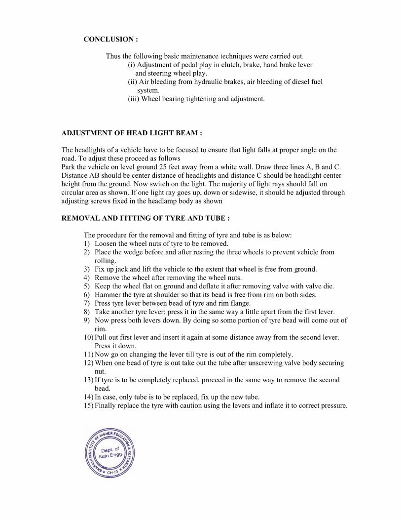
ADJUSTMENT OF HEAD LIGHT BEAM :
The headlights of a vehicle have to be focused to ensure that light falls at proper angle on the
road. To adjust these proceed as follows
Park the vehicle on level ground 25 feet away from a white wall. Draw three lines A, B and C.
Distance AB should be center distance of headlights and distance C should be headlight center
height from the ground. Now switch on the light. The majority of light rays should fall on
circular area as shown. If one light ray goes up, down or sidewise, it should be adjusted through
adjusting screws fixed in the headlamp body as shown
REMOVAL AND FITTING OF TYRE AND TUBE :
The procedure for the removal and fitting of tyre and tube is as below:
1) Loosen the wheel nuts of tyre to be removed.
2) Place the wedge before and after resting the three wheels to prevent vehicle from
rolling.
3) Fix up jack and lift the vehicle to the extent that wheel is free from ground.
4) Remove the wheel after removing the wheel nuts.
5) Keep the wheel flat on ground and deflate it after removing valve with valve die.
6) Hammer the tyre at shoulder so that its bead is free from rim on both sides.
7) Press tyre lever between bead of tyre and rim flange.
8) Take another tyre lever; press it in the same way a little apart from the first lever.
9) Now press both levers down. By doing so some portion of tyre bead will come out of
rim.
10) Pull out first lever and insert it again at some distance away from the second lever.
Press it down.
11) Now go on changing the lever till tyre is out of the rim completely.
12) When one bead of tyre is out take out the tube after unscrewing valve body securing
nut.
13) If tyre is to be completely replaced, proceed in the same way to remove the second
bead.
14) In case, only tube is to be replaced, fix up the new tube.
15) Finally replace the tyre with caution using the levers and inflate it to correct pressure.
CONCLUSION: Thus the following basic maintenance techniques were carried out.
(i) Adjustment of pedal play in clutch, brake, hand brake lever
and steering wheel play.
(ii) Air bleeding from hydraulic brakes, air bleeding of diesel fuel
system.
(iii) Wheel bearing tightening and adjustment.
(iv) Adjustment of head light beam
(v) Removal and fitting of tyre and tube.