Embed Size (px)
Citation preview
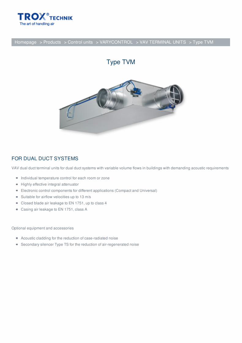
Type TVM
FOR DUAL DUCT SYSTEMS
VAV dual duct terminal units for dual duct systems with variable volume flows in buildings with demanding acoustic requirements
Individual temperature control for each room or zone
Highly effective integral attenuator
Electronic control components for different applications (Compact and Universal)
Suitable for airflow velocities up to 13 m/s
Closed blade air leakage to EN 1751, up to class 4
Casing air leakage to EN 1751, class A
Optional equipment and accessories
Acoustic cladding for the reduction of case-radiated noise
Secondary silencer Type TS for the reduction of air-regenerated noise
Homepage > Products > Control units > VARYCONTROL > VAV TERMINAL UNITS > Type TVM
APPLICATION
Application
VARYCONTROL VAV dual duct terminal units of Type TVM for the supply air
control in dual duct variable or constant air volume systems
Closed-loop volume flow control using an external power supply
For maximum acoustic and thermal comfort
Demand-based mixing of cold and warm air
Shut-off by means of switching (equipment supplied by others)
Special characteristics
Integral differential pressure sensor with 3 mm measuring holes (resistant to dust
and pollution)
Integral attenuator with at least 26 dB insertion loss at 250 Hz
Factory set-up or programming and aerodynamic function testing
Volume flow rate can later be measured and adjusted on site; additional
adjustment device may be necessary
Inspection access for cleaning to VDI 6022
Nominal sizes
TVM-S: 125, 160, 200
TVM: 125, 160, 200, 250, 315, 400
DESCRIPTION
Variants
TVM-S Dual duct unit, 60° spigot arrangement
TVM-S-D Dual duct unit with acoustic cladding, 60° spigot arrangement
TVM: Dual duct unit, 90° spigot arrangement
TVM-D: Dual duct unit with acoustic cladding, 90° spigot arrangement
Units with acoustic cladding and/or secondary silencer Type TS for very
demanding acoustic requirements
Acoustic cladding cannot be retrofitted
Parts and characteristics
Ready-to-commission unit which consists of mechanical parts and control
components.
Averaging differential pressure sensors for volume flow rate measurement, one in
the cold air spigot and one in the silencer
Damper blade
Integral attenuator
Inspection access
Factory assembled control components complete with wiring and tubing
Aerodynamic functional testing on a special test rig prior to shipping of each unit
Set-up data is given on a label or volume flow rate scale affixed to the unit
High control accuracy (even with upstream bend R = 1D)
Attachments
Compact controller: Compact unit consisting of controller, differential pressure
transducer and actuator
Universal controller: Controller, differential pressure transducer and actuators for
special applications
Accessories
Lip seals (factory fitted)
Useful additions
Secondary silencer Type TS
Construction features
Rectangular casing
Spigot on the fan end suitable for circular ducts to EN 1506 or EN 13180
Spigot with groove for lip seal
Connection on the room end suitable for air duct profiles
Baffle plate is fitted after the damper blade for optimum aerodynamic performance
Position of the damper blade indicated externally at shaft extension
Thermal and acoustic insulation (lining)
Materials and surfaces
Casing and damper blade made of galvanised sheet steel
Damper blade seal made of TPE plastic
Lining is mineral wool
Differential pressure sensor made of aluminium
Plastic bearings
Variant with acoustic cladding (-D)
Acoustic cladding made of galvanised sheet steel
Lining is mineral wool
Rubber elements for the insulation of structure-borne noise
Mineral wool
To EN 13501, fire rating class A1, non-combustible
RAL quality mark RAL-GZ 388
Biosoluble and hence hygienically safe according to the German TRGS 905
(Technical Rules for Hazardous Substances) and EU directive 97/69/EG
Faced with glass fibre fabric as protection against erosion through airflow velocities
of up to 20 m/s
Inert to fungal and bacterial growth
Standards and guidelines
Hygiene conforms to VDI 6022
VDI 2083, air cleanliness class 3, and US standard 209E, class 100
Closed blade air leakage to EN 1751, class 4 (nominal sizes 125 and 160, class 3).
Nominal sizes 125 and 160 meet the general requirements, nominal sizes 200 –
400 meet the increased requirements of DIN 1946, part 4, with regard to the
acceptable closed blade air leakage
Casing air leakage to EN 1751, class A
Maintenance
Maintenance-free as construction and materials are not subject to wear
TECHNICAL INFORMATION
Function, Technical data, Quick sizing, Specification text, Order code, Related Products
FUNCTION
Functional description
The VAV terminal unit is fitted with two differential pressure sensors for measuring the volume flow rates, one in the cold
air flow and one in the total air flow.
The control components (attachments) include two differential pressure transducers that transform the differential
pressure (effective pressure) into an electric signal, two controllers, and two actuators; the control functions can be
achieved with a Compact controller or with individual components.
In most cases, the setpoint value for the dual duct terminal unit comes from a room temperature controller.
The room temperature controller 'leads' the cold air volume flow controller and alters the setpoint for the cold air flow rate
between 0 and the maximum volume flow V . The controller compares the actual value with the setpoint value and
alters the control signal of the damper actuator if there is a difference between the two values.
The warm/total air controller is set to the minimum volume flow rate V and controls the warm air damper blade. As a
consequence, a corresponding proportion of warm air is added. As the demand for cooling increases, the warm air
damper blade closes such that eventually only cold air flows.
An integral attenuator reduces the noise that is created by the restriction of the airflow.
The airflow velocity at the room end is, due to the larger rectangular cross section, about half the velocity in the circular
duct.
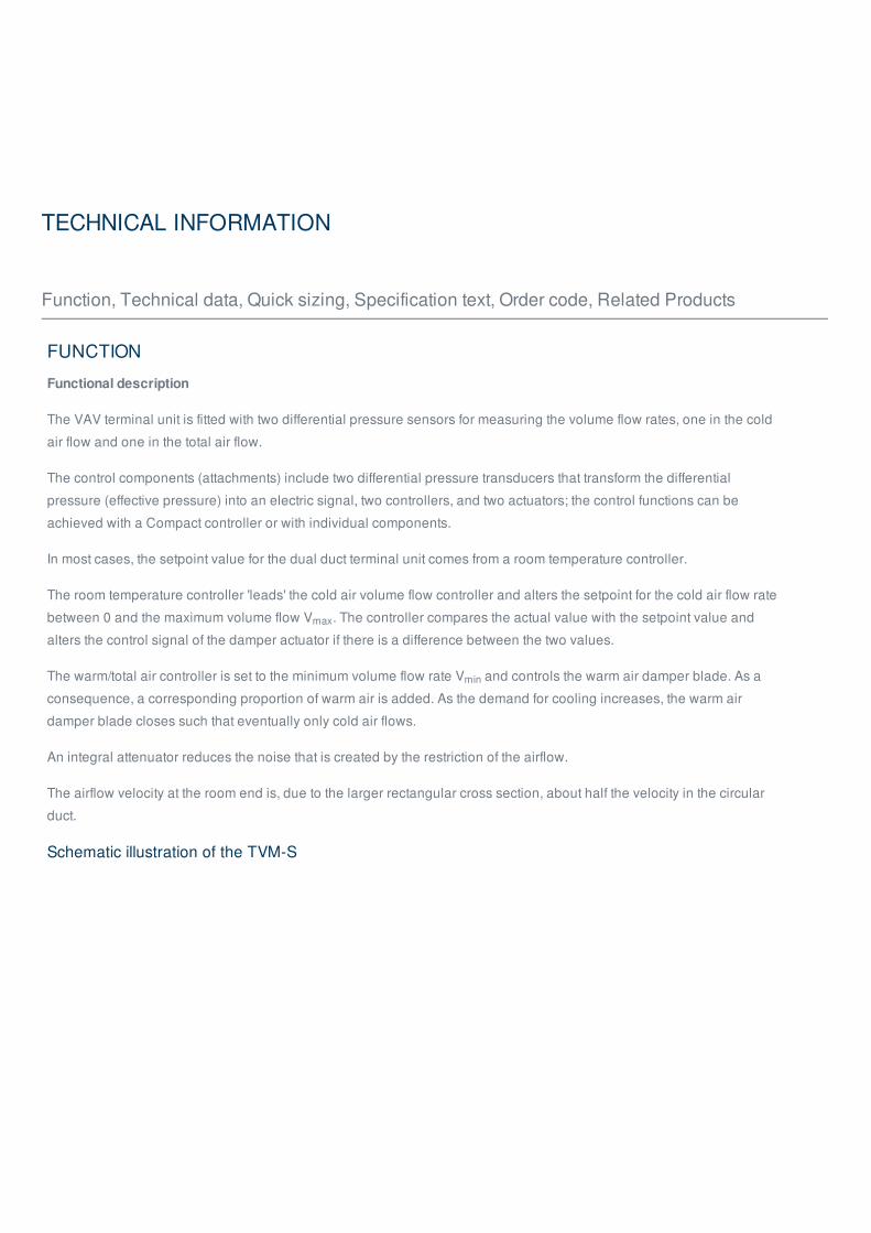
Schematic illustration of the TVM-S
max
min
① Damper blade – cold air② Lip seal③ Differential pressure sensor – cold air④ Control components, e. g. a Compact controller⑤ Inspection access⑥ Differential pressure sensor – total air⑦ Acoustic insulation⑧ Damper blade – warm air
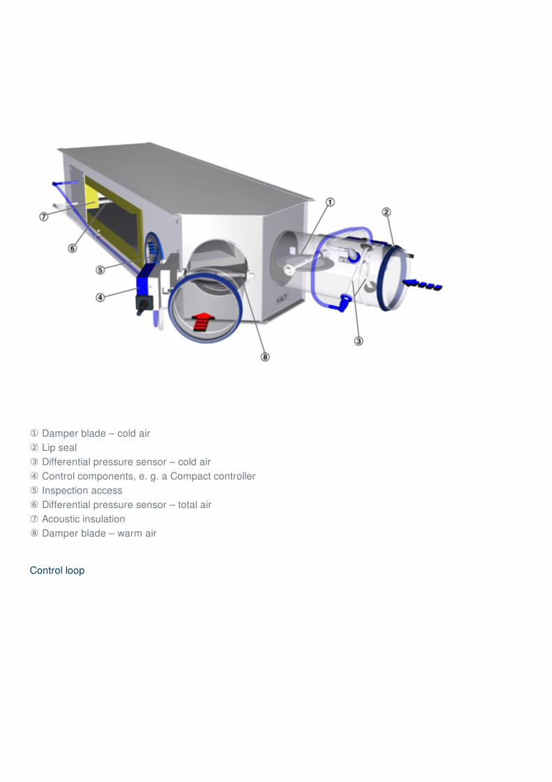
Control loop
① Effective pressure transducer④ Actuator for cold air duct③ Volume flow controller④ Setpoint value signal⑤ Effective pressure transducer for V ⑥ Actuator for warm air duct⑦ Volume flow controller for V (V )
Control diagram
① Cold air supply
tot
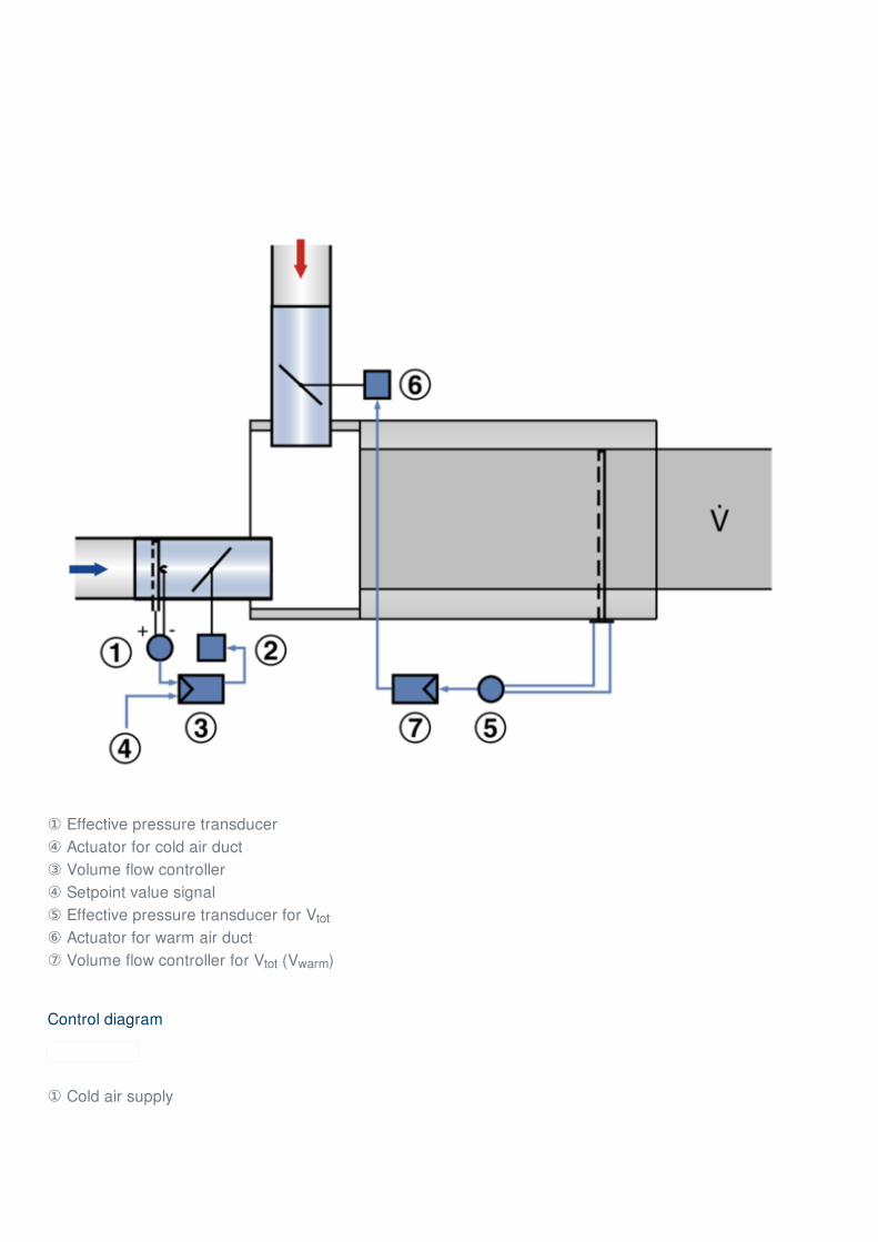
tot warm
② Warm air supply③ Total extract air at the unit outlet
Single operation
Slave operation (master-slave)
Static differential pressure
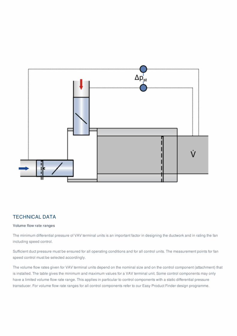
TECHNICAL DATA
Volume flow rate ranges
The minimum differential pressure of VAV terminal units is an important factor in designing the ductwork and in rating the fan
including speed control.
Sufficient duct pressure must be ensured for all operating conditions and for all control units. The measurement points for fan
speed control must be selected accordingly.
The volume flow rates given for VAV terminal units depend on the nominal size and on the control component (attachment) that
is installed. The table gives the minimum and maximum values for a VAV terminal unit. Some control components may only
have a limited volume flow rate range. This applies in particular to control components with a static differential pressure
transducer. For volume flow rate ranges for all control components refer to our Easy Product Finder design programme.
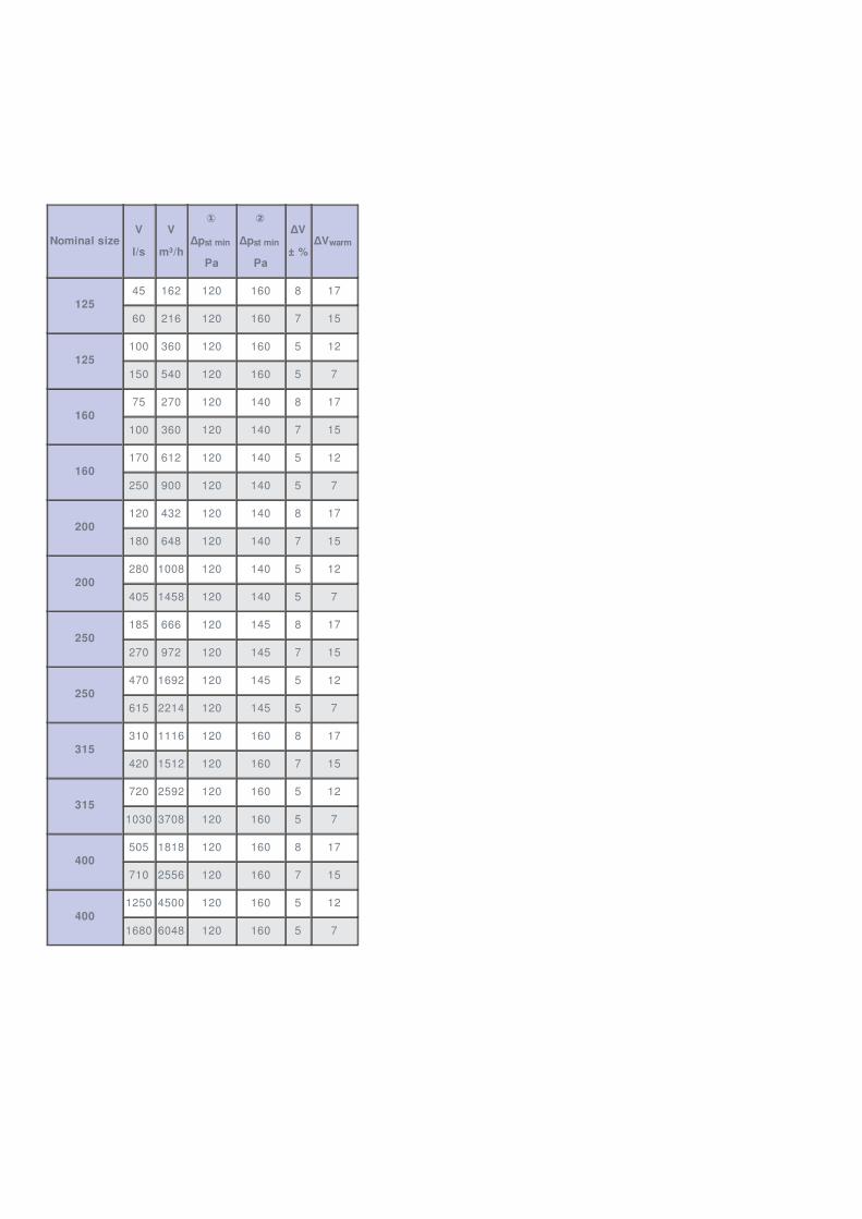
Nominal sizeV
l/s
V
m³/h
①
Δp
Pa
②
Δp
Pa
ΔV
± %ΔV
12545 162 120 160 8 17
60 216 120 160 7 15
125100 360 120 160 5 12
150 540 120 160 5 7
16075 270 120 140 8 17
100 360 120 140 7 15
160170 612 120 140 5 12
250 900 120 140 5 7
200120 432 120 140 8 17
180 648 120 140 7 15
200280 1008 120 140 5 12
405 1458 120 140 5 7
250185 666 120 145 8 17
270 972 120 145 7 15
250470 1692 120 145 5 12
615 2214 120 145 5 7
315310 1116 120 160 8 17
420 1512 120 160 7 15
315720 2592 120 160 5 12
1030 3708 120 160 5 7
400505 1818 120 160 8 17
710 2556 120 160 7 15
4001250 4500 120 160 5 12
1680 6048 120 160 5 7
st min st min warm
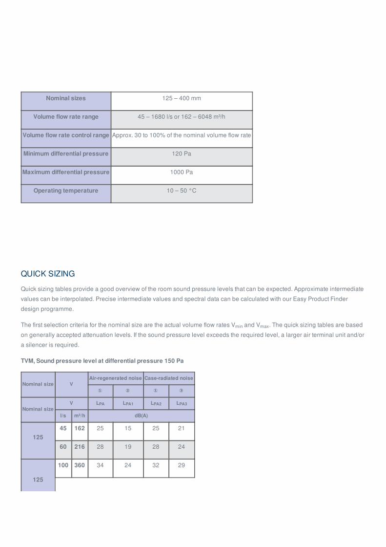
Nominal sizes 125 – 400 mm
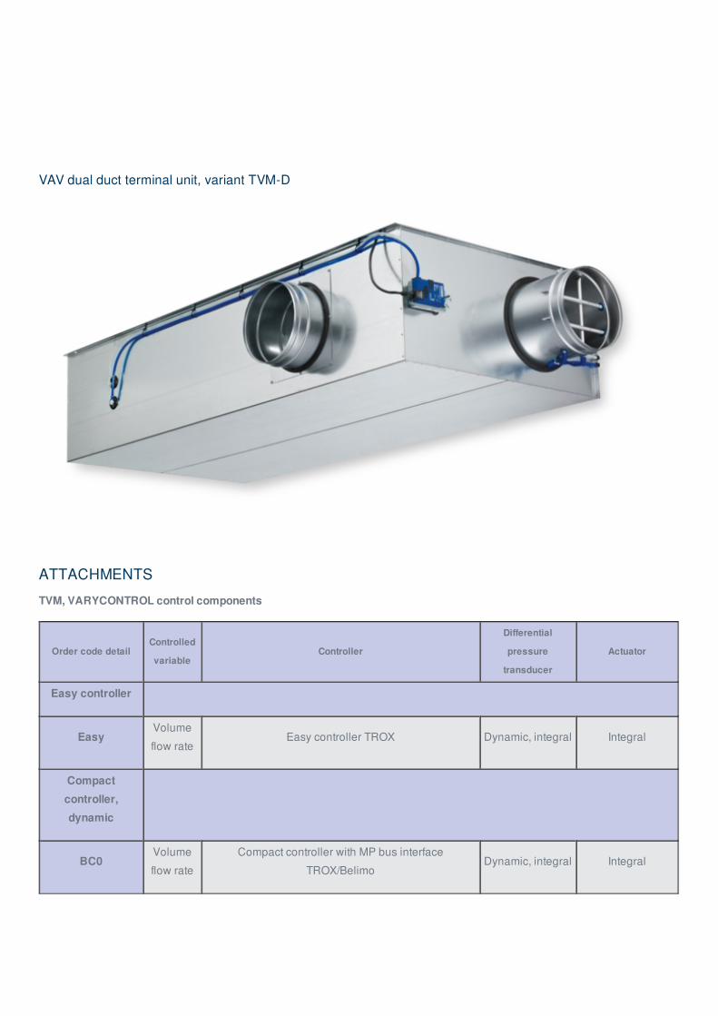
Volume flow rate range 45 – 1680 l/s or 162 – 6048 m³/h
Volume flow rate control range Approx. 30 to 100% of the nominal volume flow rate
Minimum differential pressure 120 Pa
Maximum differential pressure 1000 Pa
Operating temperature 10 – 50 °C
QUICK SIZING
Quick sizing tables provide a good overview of the room sound pressure levels that can be expected. Approximate intermediate
values can be interpolated. Precise intermediate values and spectral data can be calculated with our Easy Product Finder
design programme.
The first selection criteria for the nominal size are the actual volume flow rates V and V . The quick sizing tables are based
on generally accepted attenuation levels. If the sound pressure level exceeds the required level, a larger air terminal unit and/or
a silencer is required.
TVM, Sound pressure level at differential pressure 150 Pa
Nominal size VAir-regenerated noise Case-radiated noise
① ② ① ③
Nominal sizeV L L L L
l/s m³/h dB(A)
12545 162 25 15 25 21
60 216 28 19 28 24
125
100 360 34 24 32 29
min max
PA PA1 PA2 PA3
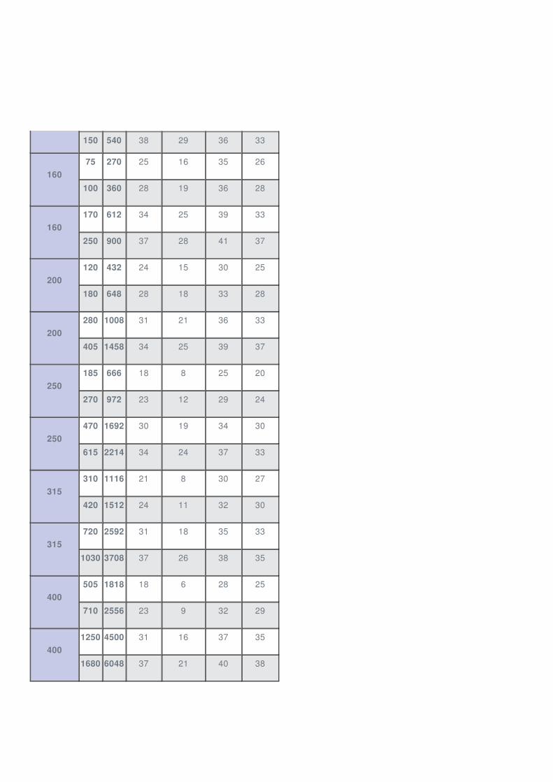
150 540 38 29 36 33
16075 270 25 16 35 26
100 360 28 19 36 28
160170 612 34 25 39 33
250 900 37 28 41 37
200120 432 24 15 30 25
180 648 28 18 33 28
200280 1008 31 21 36 33
405 1458 34 25 39 37
250185 666 18 8 25 20
270 972 23 12 29 24
250470 1692 30 19 34 30
615 2214 34 24 37 33
315310 1116 21 8 30 27
420 1512 24 11 32 30
315720 2592 31 18 35 33
1030 3708 37 26 38 35
400505 1818 18 6 28 25
710 2556 23 9 32 29
4001250 4500 31 16 37 35
1680 6048 37 21 40 38
① TVM, TVM-S
② TVM, TVM-S with secondary silencer TS
③ TVM-D, TVM-S-D
SPECIFICATION TEXT
Rectangular VAV dual duct terminal units for dual duct systems with variable and constant volume flows, available in 6 nominal
sizes.
Connecting spigots for warm and cold air arranged at an angle of 90°. Up to nominal size 200 an angle of 60° is also possible,
hence ideal for for the refurbishment of older systems with dual duct units.
High control accuracy (even with upstream bend R = 1D).
Ready-to-commission unit which consists of the mechanical parts and the electronic control components. Each unit contains
two averaging differential pressure sensors for volume flow rate measurement, one in the cold air flow and one in the total air
flow, two damper blades, and an integral attenuator. Factory-assembled control components complete with wiring and tubing.
Differential pressure sensor with 3 mm measuring holes (resistant to dust and pollution)
On the fan end, spigot with groove for lip seal, suitable for connecting ducts to EN 1506 or EN 13180.
Room end suitable for the connection of air duct profiles.
Two baffle plates, one fitted after each damper blade for optimum acoustic and aerodynamic performance.
Casing with acoustic and thermal insulation.
Position of the damper blade indicated externally at shaft extension.
Closed blade air leakage to EN 1751, class 4 (nominal sizes 125 and 160, class 3).
Casing air leakage to EN 1751, class B.
Complies with VDI 2083, clean room class 3, and US standard 209E, class 100. Hygiene complies with VDI 6022, DIN 1946,
part 4, as well as EN 13779 and VDI 3803.
Special characteristics
Integral differential pressure sensor with 3 mm measuring holes (resistant to dust and pollution)
Integral attenuator with at least 26 dB insertion loss at 250 Hz
Factory set-up or programming and aerodynamic function testing
Volume flow rate can later be measured and adjusted on site; additional adjustment device may be necessary
Inspection access for cleaning to VDI 6022
Materials and surfaces
Casing and damper blade made of galvanised sheet steel
Damper blade seal made of TPE plastic
Lining is mineral wool
Differential pressure sensor made of aluminium
Plastic bearings
Variant with acoustic cladding (-D)
Acoustic cladding made of galvanised sheet steel
Lining is mineral wool
Rubber elements for the insulation of structure-borne noise
Mineral wool
To EN 13501, fire rating class A1, non-combustible
RAL quality mark RAL-GZ 388
Biosoluble and hence hygienically safe according to the German TRGS 905 (Technical Rules for Hazardous Substances)
and EU directive 97/69/EG
Faced with glass fibre fabric as protection against erosion through airflow velocities of up to 20 m/s
Inert to fungal and bacterial growth
Technical data
Nominal sizes: 125 to 400 mm
Volume flow rate range: 45 to 1680 l/s or 162 to 6048 m³/h
Volume flow rate control range: approx. 30 – 100 % of the nominal volume flow rate
Minimum differential pressure: 120 Pa
Maximum differential pressure: 1000 Pa
Attachments
Variable volume flow control with electronic Compact controller to switch an external control signal and an actual value signal
for integration into the central BMS.
Supply voltage 24 V AC/DC
Signal voltages 0 – 10 V DC or 2 – 10 V DC
Possible override controls with external switches using volt-free contacts: CLOSED, OPEN, V and V
Volume flow rate control range: approx. 30 – 100 % of the nominal volume flow rate
Sizing data
V – V [m³/h]
V – V [m³/h]
Δp [Pa]
L air-regenerated noise[dB(A)]
L Case-radiated noise[dB(A)]
This specification text describes the general properties of the product. Texts for variants can be generated with our Easy Product
Finder design programme.
min max
warm, min warm, max
cold, min cold, max
st
PA
PA
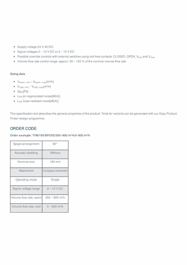
ORDER CODE
Order example: TVM/160/BF0/E0/300–900 m³/h/0–900 m³/h
Spigot arrangement 90°
Acoustic cladding Without
Nominal size 160 mm
Attachment Compact controller
Operating mode Single
Signal voltage range 0 – 10 V DC
Volume flow rate, warm 300 – 900 m³/h
Volume flow rate, cold 0 – 900 m³/h
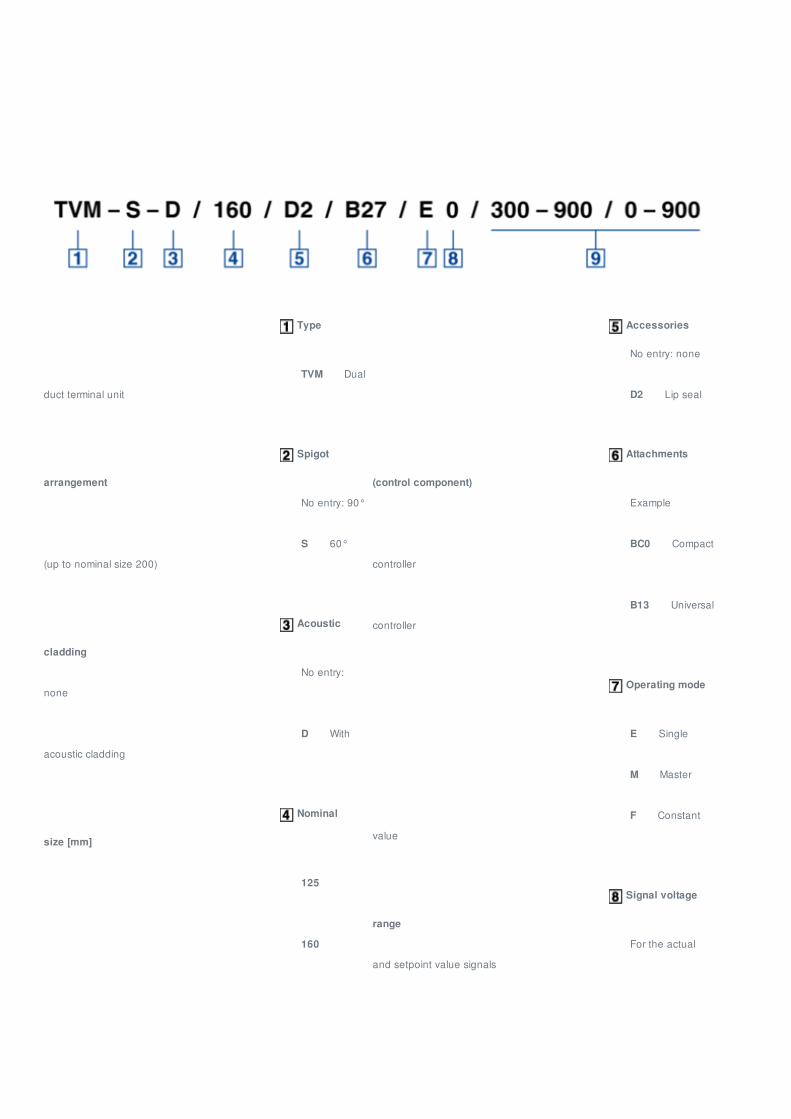
Type
TVM Dual
duct terminal unit
Spigot
arrangement
No entry: 90°
S 60°
(up to nominal size 200)
Acoustic
cladding
No entry:
none
D With
acoustic cladding
Nominal
size [mm]
125
160
Accessories
No entry: none
D2 Lip seal
Attachments
(control component)
Example
BC0 Compact
controller
B13 Universal
controller
Operating mode
E Single
M Master
F Constant
value
Signal voltage
range
For the actual
and setpoint value signals
Variants, Attachments, Dimensions and weight, Product details
200
250
315
400
0 0 – 10 V DC
2 2 – 10 V DC
Volume flow
rates [m³/h or l/s]
V
– V / V – V for factory setting
warm,
min warm, max cold, min cold, max
RELATED PRODUCTS
AttachmentsType Compact, dynamic
Type Compact, static
Type Universal, dynamic
Additional productsType TS
VARIANTS
TVM-S
VAV terminal unit for the control of variable supply air volume flows
Connecting spigots for warm and cold air arranged at an angle of 60°
TVM-S-D
VAV terminal unit with acoustic cladding for the control of variable supply air volume flows
Connecting spigots for warm and cold air arranged at an angle of 60°
For rooms where the case-radiated noise of the unit is not sufficiently reduced by a false ceiling
The circular ducts for the room under consideration must have adequate acoustic insulation (provided by others) on
the fan end
Acoustic cladding cannot be retrofitted
TVM
VAV terminal unit for the control of variable supply air volume flows
Connecting spigots for warm and cold air arranged at an angle of 90°
TVM-D
VAV terminal unit with acoustic cladding for the control of variable supply air volume flows
Connecting spigots for warm and cold air arranged at an angle of 90°
For rooms where the case-radiated noise of the unit is not sufficiently reduced by a false ceiling
The circular ducts for the room under consideration must have adequate acoustic insulation (provided by others) on
the fan end
Acoustic cladding cannot be retrofitted
VAV dual duct terminal unit, variant TVM-S
VAV dual duct terminal unit, variant TVM-S-D
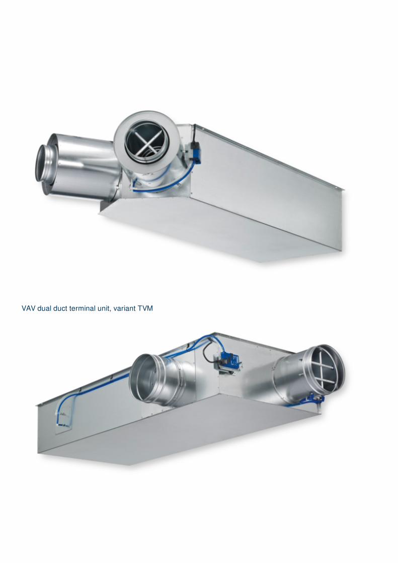
VAV dual duct terminal unit, variant TVM
VAV dual duct terminal unit, variant TVM-D
ATTACHMENTS
TVM, VARYCONTROL control components
Order code detailControlled
variableController
Differential
pressure
transducer
Actuator
Easy controller
EasyVolume
flow rateEasy controller TROX Dynamic, integral Integral
Compact
controller,
dynamic
BC0Volume
flow rate
Compact controller with MP bus interface
TROX/BelimoDynamic, integral Integral
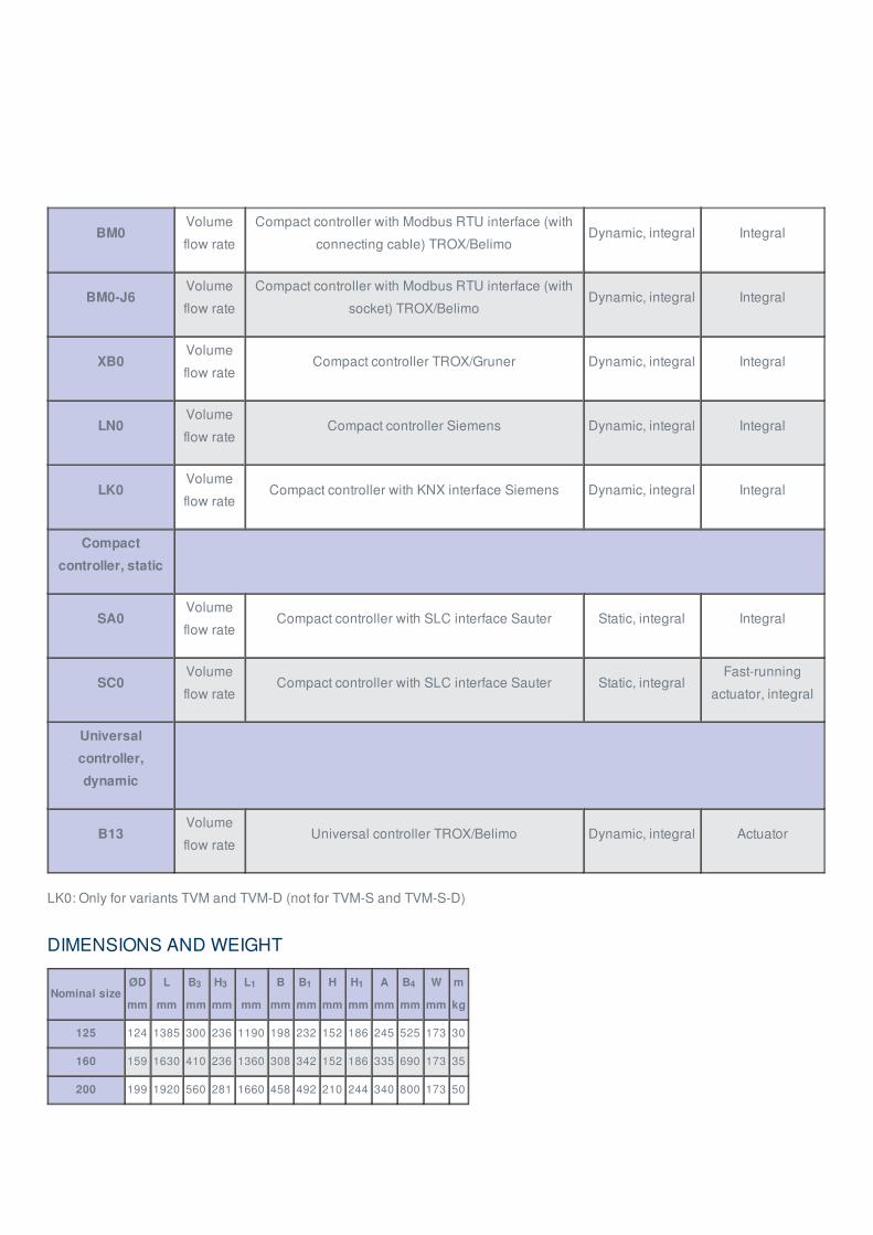
BM0Volume
flow rate
Compact controller with Modbus RTU interface (with
connecting cable) TROX/BelimoDynamic, integral Integral
BM0-J6Volume
flow rate
Compact controller with Modbus RTU interface (with
socket) TROX/BelimoDynamic, integral Integral
XB0Volume
flow rateCompact controller TROX/Gruner Dynamic, integral Integral
LN0Volume
flow rateCompact controller Siemens Dynamic, integral Integral
LK0Volume
flow rateCompact controller with KNX interface Siemens Dynamic, integral Integral
Compact
controller, static
SA0Volume
flow rateCompact controller with SLC interface Sauter Static, integral Integral
SC0Volume
flow rateCompact controller with SLC interface Sauter Static, integral
Fast-running
actuator, integral
Universal
controller,
dynamic
B13Volume
flow rateUniversal controller TROX/Belimo Dynamic, integral Actuator
LK0: Only for variants TVM and TVM-D (not for TVM-S and TVM-S-D)
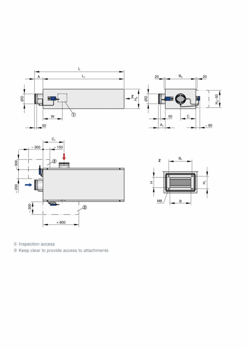
DIMENSIONS AND WEIGHT
Nominal sizeØD
mm
L
mm
B
mm
H
mm
L
mm
B
mm
B
mm
H
mm
H
mm
A
mm
B
mm
W
mm
m
kg
125 124 1385 300 236 1190 198 232 152 186 245 525 173 30
160 159 1630 410 236 1360 308 342 152 186 335 690 173 35
200 199 1920 560 281 1660 458 492 210 244 340 800 173 50
3 3 1 1 1 4
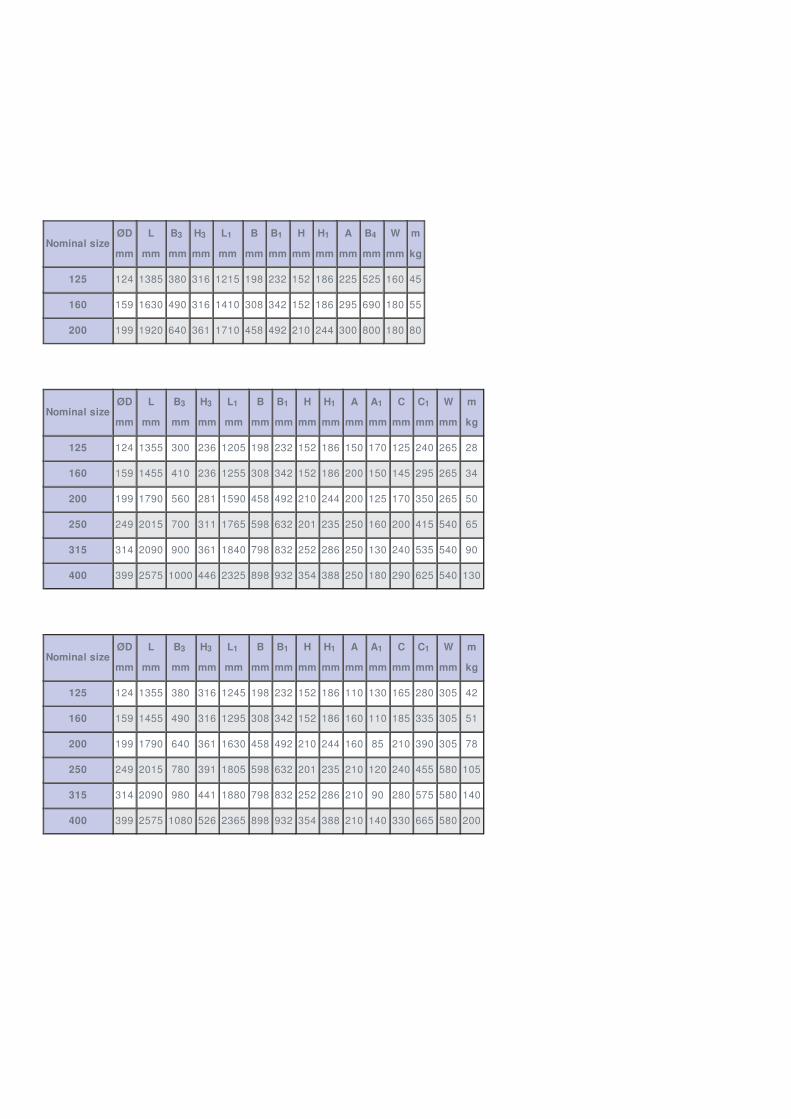
Nominal sizeØD
mm
L
mm
B
mm
H
mm
L
mm
B
mm
B
mm
H
mm
H
mm
A
mm
B
mm
W
mm
m
kg
125 124 1385 380 316 1215 198 232 152 186 225 525 160 45
160 159 1630 490 316 1410 308 342 152 186 295 690 180 55
200 199 1920 640 361 1710 458 492 210 244 300 800 180 80
Nominal sizeØD
mm
L
mm
B
mm
H
mm
L
mm
B
mm
B
mm
H
mm
H
mm
A
mm
A
mm
C
mm
C
mm
W
mm
m
kg
125 124 1355 300 236 1205 198 232 152 186 150 170 125 240 265 28
160 159 1455 410 236 1255 308 342 152 186 200 150 145 295 265 34
200 199 1790 560 281 1590 458 492 210 244 200 125 170 350 265 50
250 249 2015 700 311 1765 598 632 201 235 250 160 200 415 540 65
315 314 2090 900 361 1840 798 832 252 286 250 130 240 535 540 90
400 399 2575 1000 446 2325 898 932 354 388 250 180 290 625 540 130
Nominal sizeØD
mm
L
mm
B
mm
H
mm
L
mm
B
mm
B
mm
H
mm
H
mm
A
mm
A
mm
C
mm
C
mm
W
mm
m
kg
125 124 1355 380 316 1245 198 232 152 186 110 130 165 280 305 42
160 159 1455 490 316 1295 308 342 152 186 160 110 185 335 305 51
200 199 1790 640 361 1630 458 492 210 244 160 85 210 390 305 78
250 249 2015 780 391 1805 598 632 201 235 210 120 240 455 580 105
315 314 2090 980 441 1880 798 832 252 286 210 90 280 575 580 140
400 399 2575 1080 526 2365 898 932 354 388 210 140 330 665 580 200
3 3 1 1 1 4
3 3 1 1 1 1 1
3 3 1 1 1 1 1
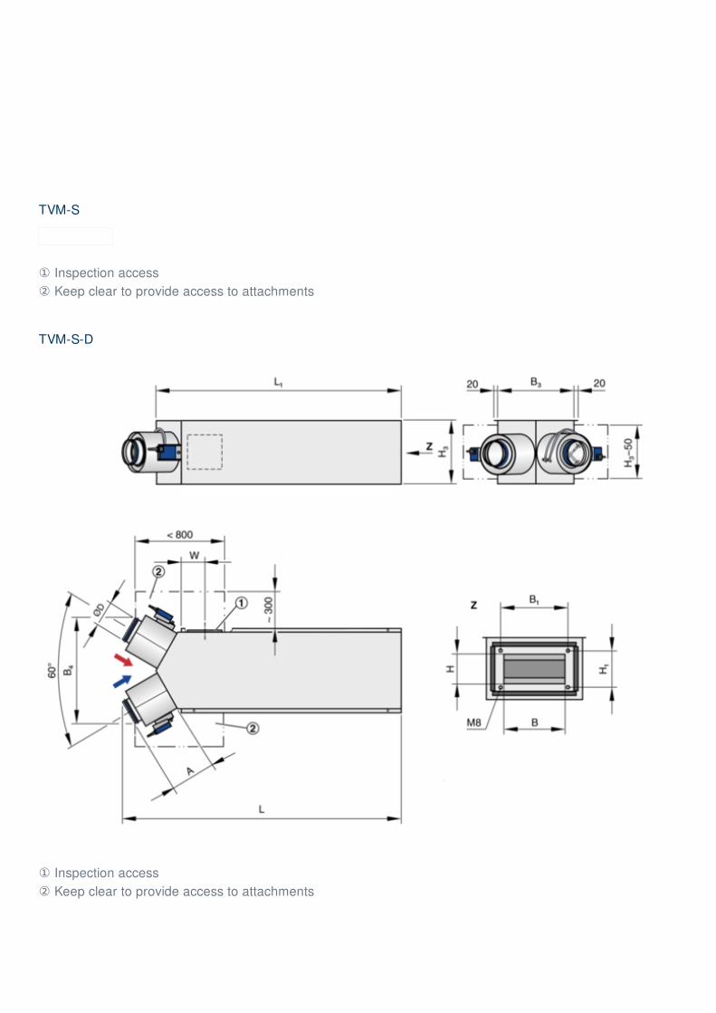
TVM-S
① Inspection access② Keep clear to provide access to attachments
TVM-S-D
① Inspection access② Keep clear to provide access to attachments
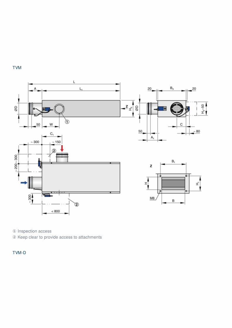
TVM
① Inspection access② Keep clear to provide access to attachments
TVM-D
① Inspection access② Keep clear to provide access to attachments
Installation details, Basic information and nomenclature
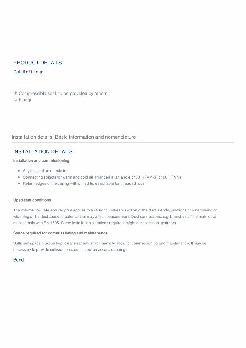
PRODUCT DETAILS
Detail of flange
① Compressible seal, to be provided by others② Flange
INSTALLATION DETAILS
Installation and commissioning
Any installation orientation
Connecting spigots for warm and cold air arranged at an angle of 60° (TVM-S) or 90° (TVM)
Return edges of the casing with drilled holes suitable for threaded rods
Upstream conditions
The volume flow rate accuracy ΔV applies to a straight upstream section of the duct. Bends, junctions or a narrowing or
widening of the duct cause turbulence that may affect measurement. Duct connections, e.g. branches off the main duct,
must comply with EN 1505. Some installation situations require straight duct sections upstream.
Space required for commissioning and maintenance
Sufficient space must be kept clear near any attachments to allow for commissioning and maintenance. It may be
necessary to provide sufficiently sized inspection access openings.
Bend
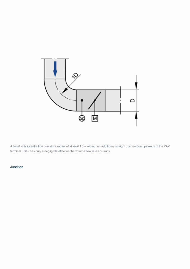
A bend with a centre line curvature radius of at least 1D – without an additional straight duct section upstream of the VAV
terminal unit – has only a negligible effect on the volume flow rate accuracy.
Junction
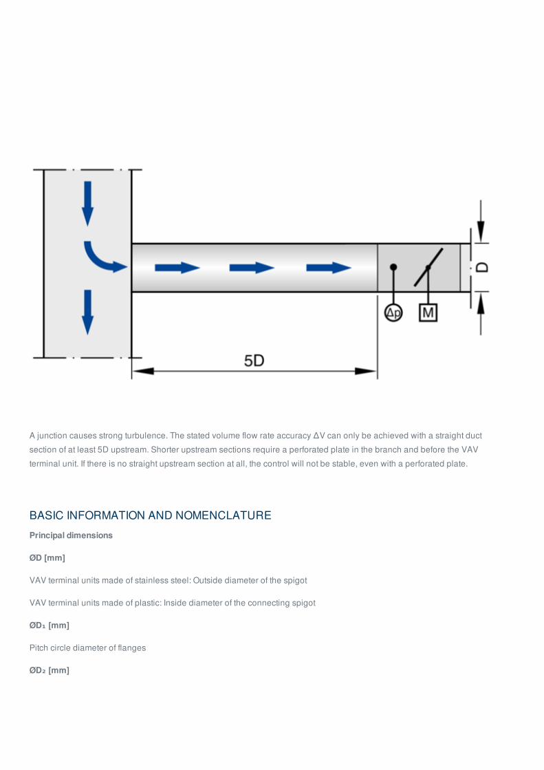
A junction causes strong turbulence. The stated volume flow rate accuracy ΔV can only be achieved with a straight duct
section of at least 5D upstream. Shorter upstream sections require a perforated plate in the branch and before the VAV
terminal unit. If there is no straight upstream section at all, the control will not be stable, even with a perforated plate.
BASIC INFORMATION AND NOMENCLATURE
Principal dimensions
ØD [mm]
VAV terminal units made of stainless steel: Outside diameter of the spigot
VAV terminal units made of plastic: Inside diameter of the connecting spigot
ØD₁ [mm]
Pitch circle diameter of flanges
ØD₂ [mm]
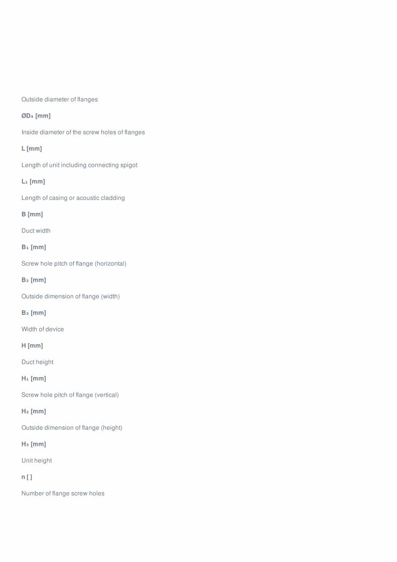
Outside diameter of flanges
ØD₄ [mm]
Inside diameter of the screw holes of flanges
L [mm]
Length of unit including connecting spigot
L₁ [mm]
Length of casing or acoustic cladding
B [mm]
Duct width
B₁ [mm]
Screw hole pitch of flange (horizontal)
B₂ [mm]
Outside dimension of flange (width)
B₃ [mm]
Width of device
H [mm]
Duct height
H₁ [mm]
Screw hole pitch of flange (vertical)
H₂ [mm]
Outside dimension of flange (height)
H₃ [mm]
Unit height
n [ ]
Number of flange screw holes
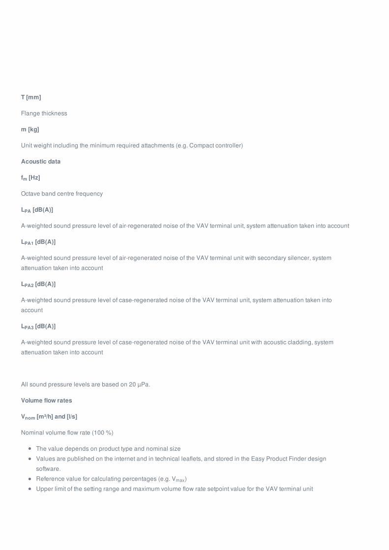
T [mm]
Flange thickness
m [kg]
Unit weight including the minimum required attachments (e.g. Compact controller)
Acoustic data
f [Hz]
Octave band centre frequency
L [dB(A)]
A-weighted sound pressure level of air-regenerated noise of the VAV terminal unit, system attenuation taken into account
L [dB(A)]
A-weighted sound pressure level of air-regenerated noise of the VAV terminal unit with secondary silencer, system
attenuation taken into account
L [dB(A)]
A-weighted sound pressure level of case-regenerated noise of the VAV terminal unit, system attenuation taken into
account
L [dB(A)]
A-weighted sound pressure level of case-regenerated noise of the VAV terminal unit with acoustic cladding, system
attenuation taken into account
All sound pressure levels are based on 20 µPa.
Volume flow rates
V [m³/h] and [l/s]
Nominal volume flow rate (100 %)
The value depends on product type and nominal size
Values are published on the internet and in technical leaflets, and stored in the Easy Product Finder design
software.
Reference value for calculating percentages (e.g. V )
Upper limit of the setting range and maximum volume flow rate setpoint value for the VAV terminal unit
m
PA
PA1
PA2
PA3
nom
max
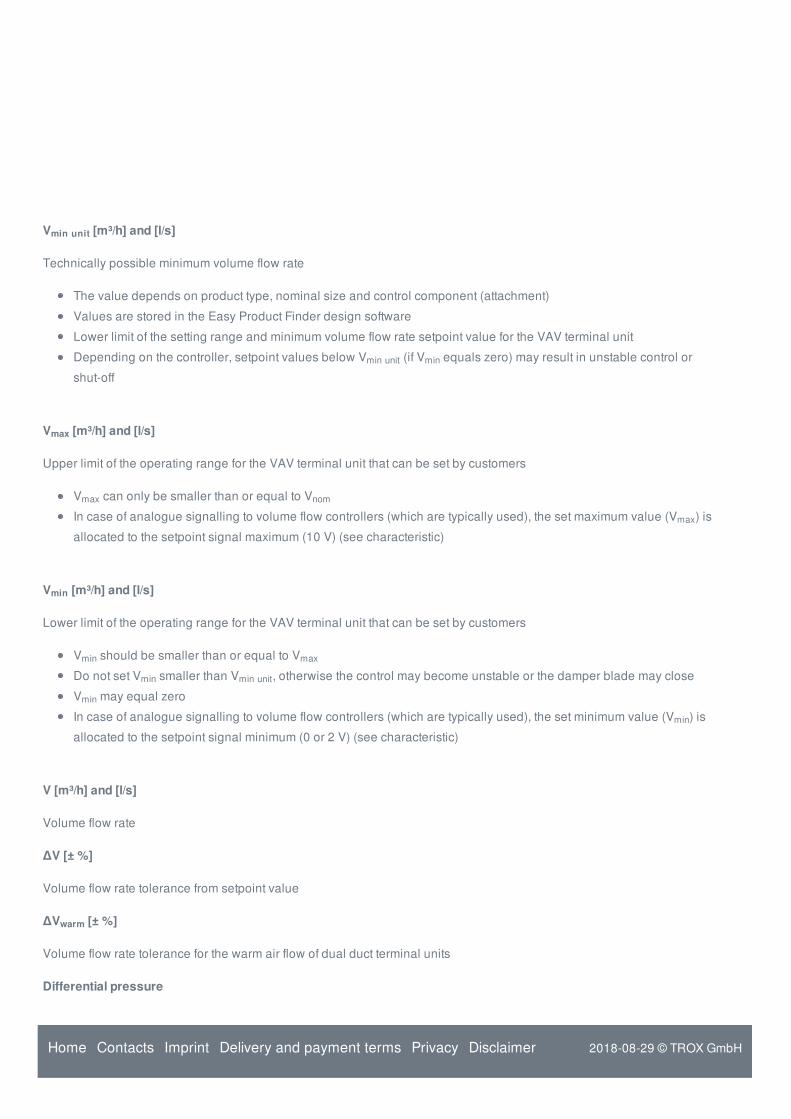
V [m³/h] and [l/s]
Technically possible minimum volume flow rate
The value depends on product type, nominal size and control component (attachment)
Values are stored in the Easy Product Finder design software
Lower limit of the setting range and minimum volume flow rate setpoint value for the VAV terminal unit
Depending on the controller, setpoint values below V (if V equals zero) may result in unstable control or
shut-off
V [m³/h] and [l/s]
Upper limit of the operating range for the VAV terminal unit that can be set by customers
V can only be smaller than or equal to V
In case of analogue signalling to volume flow controllers (which are typically used), the set maximum value (V ) is
allocated to the setpoint signal maximum (10 V) (see characteristic)
V [m³/h] and [l/s]
Lower limit of the operating range for the VAV terminal unit that can be set by customers
V should be smaller than or equal to V
Do not set V smaller than V , otherwise the control may become unstable or the damper blade may close
V may equal zero
In case of analogue signalling to volume flow controllers (which are typically used), the set minimum value (V ) is
allocated to the setpoint signal minimum (0 or 2 V) (see characteristic)
V [m³/h] and [l/s]
Volume flow rate
ΔV [± %]
Volume flow rate tolerance from setpoint value
ΔV [± %]
Volume flow rate tolerance for the warm air flow of dual duct terminal units
Differential pressure
min unit
min unit min
max
max nom
max
min
min max
min min unit
min
min
warm
Home Contacts Imprint Delivery and payment terms Privacy Disclaimer 2018-08-29 © TROX GmbH
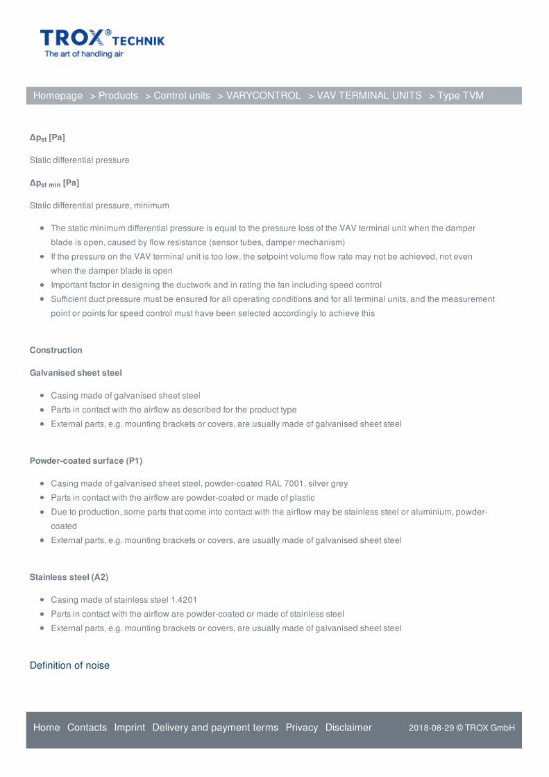
Δp [Pa]
Static differential pressure
Δp [Pa]
Static differential pressure, minimum
The static minimum differential pressure is equal to the pressure loss of the VAV terminal unit when the damper
blade is open, caused by flow resistance (sensor tubes, damper mechanism)
If the pressure on the VAV terminal unit is too low, the setpoint volume flow rate may not be achieved, not even
when the damper blade is open
Important factor in designing the ductwork and in rating the fan including speed control
Sufficient duct pressure must be ensured for all operating conditions and for all terminal units, and the measurement
point or points for speed control must have been selected accordingly to achieve this
Construction
Galvanised sheet steel
Casing made of galvanised sheet steel
Parts in contact with the airflow as described for the product type
External parts, e.g. mounting brackets or covers, are usually made of galvanised sheet steel
Powder-coated surface (P1)
Casing made of galvanised sheet steel, powder-coated RAL 7001, silver grey
Parts in contact with the airflow are powder-coated or made of plastic
Due to production, some parts that come into contact with the airflow may be stainless steel or aluminium, powder-
coated
External parts, e.g. mounting brackets or covers, are usually made of galvanised sheet steel
Stainless steel (A2)
Casing made of stainless steel 1.4201
Parts in contact with the airflow are powder-coated or made of stainless steel
External parts, e.g. mounting brackets or covers, are usually made of galvanised sheet steel
Definition of noise
st
st min
Homepage > Products > Control units > VARYCONTROL > VAV TERMINAL UNITS > Type TVM
Home Contacts Imprint Delivery and payment terms Privacy Disclaimer 2018-08-29 © TROX GmbH
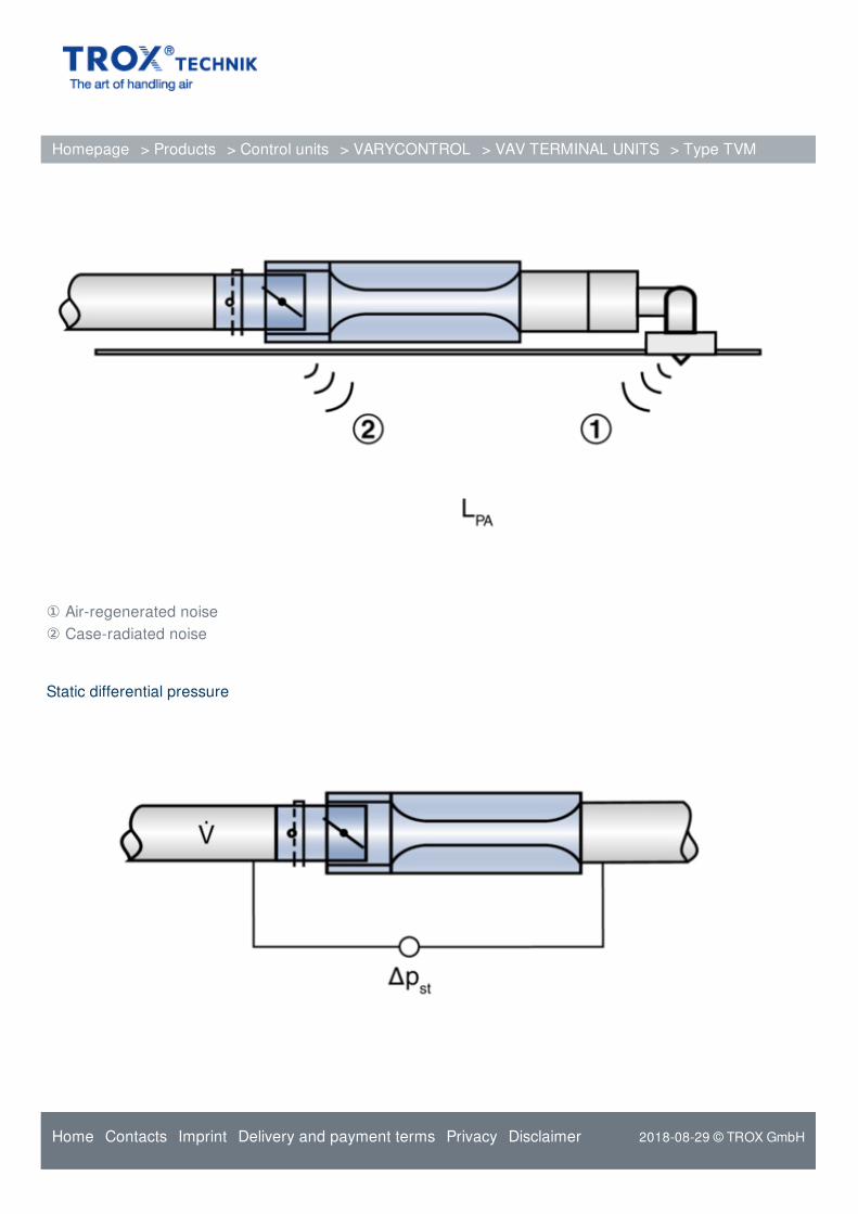
① Air-regenerated noise② Case-radiated noise
Static differential pressure
Homepage > Products > Control units > VARYCONTROL > VAV TERMINAL UNITS > Type TVM
Home Contacts Imprint Delivery and payment terms Privacy Disclaimer 2018-08-29 © TROX GmbH
TROX GmbH
Heinrich-Trox-Platz
D-47504 Neukirchen-Vluyn
Tel.: +49 (0)2845 202-0
Fax: +49 (0)2845 202-265
Online-Services
Order-Status (My TROX NET)
TROX Academy
Catalogue Download
Your contact partner
Online fault report
BIM
Service-Hotlines
Sales Germany
and technical consulting
+49 (0)2845 202-0
Contact
Technical service
+49 (0)2845 202-400
Contact
Homepage > Products > Control units > VARYCONTROL > VAV TERMINAL UNITS > Type TVM
Home Contacts Imprint Delivery and payment terms Privacy Disclaimer 2018-08-29 © TROX GmbH