Embed Size (px)
Citation preview
I. l. 41-57 4
INSTALLATION • OPERATION • MAINTENANCE
INSTRUCTIONS TYPE TK TIMING RELAY
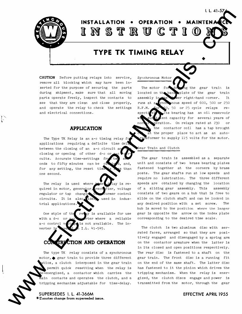
CAUTION Before putting relays into service ,
remove all blocking which may have been in
serted for the purpose of securing the part s
during shipment , make sure that all moving
p art s operate freely , insp ect the contac t s to
see that they are c lean and close properly,
and operat e the relay to check the settings
and electrical connections .
APPLICATION
The Typ e TK Relay is an a-c timing relay for
applications requiring a definite time del ay
between the closing of an a-c circuit and the
closing or opening of other d-e or a-c cir
cuit s. Ac curate time -settings from two sec
onds to fifty minutes can be obtained, and,
for any setting , the reset time is l e s s than
one second .
The relay is used where time delay is re-
quired in motor, generator , rectifier , voltage
regulator or tap changing transformer control
circuits . It is also widely used in indus-
trial applications .
One styl e of the relay is available for use
with a d-e or a-c inverter where a reliable
a-c control voltage is not available . The in
verter is covered in I . L. 41 -545 .
CONSTRUCTION AND OPERATION
The type TK relay consists of a synchronous
motor , a gear train to provide three different
ratios , a clutch interposed in the gear train
to permit quick resetting when the relay is
de -energized, a contactor which c arrie s the
main contacts and operates the clutch , and a
tripping mechanism adjustable for time-delay .
SUPERSEDES I. L. 41-366M *Demotes change from superseded issue.
Synchronous Motor
The motor for driving the gear train is
located on the back plate of the gear train
assembly in the lower right-hand corner . It
runs at a synchronous sp eed of 600, 500 or 250
R . P . M . for 60 , 50 or 25 cycle relays re
spectively . Its bearing has an oil reser·voir
with sufficient capacity for several years of
normal operation . On relays rated at 230 or
higher, the contactor coil has a tap brought
out at the proper place to act as an auto
transformer to supply 115 volts for the motor .
Gear Train and Clutch
The gear train is assembled as a separate
unit and consists of two bras s bearing plat es
fastened together at the corners by brass
posts . The gear shaft s run at low speeds and
require no lubric ation . The three different
speeds are obtained by changing the location
of a sliding gear as sembly . This as sembly
consists of two gears on a hub that is free to
s lide on the clutch shaft and can be locked in
any de sired position with a set screw . The
hub is moved to the position where the larger gear is opposite the arrow on the index plate
corresponding to the desired time scale .
The clutch is two aluminum disc with ser-
rated fac e s , arranged so that they are posi-
tively engaged and disengaged by a spring arm
on the contactor armature when the latter is
in its c losed and open positions respectively .
The rear disc is fastened to a shaft on the
gear train . The front disc is a running fit
on the end of the same shaft . The latter disc
has fastened to it the pinion which drives the
t ripping mechanism . When the relay is ener
gized, the clutch disc s engage and power is
t ransmitted from the motor, through the gear
EFFECTIVE APRIL 1955 www . El
ectric
alPar
tMan
uals
. com
TYPE TK RELAY------------------------
trai n , to the tripping mechani sm . When the
relay i s de -energized , the clutch di s c s are
separated by the opening of the contactor arm
ature .
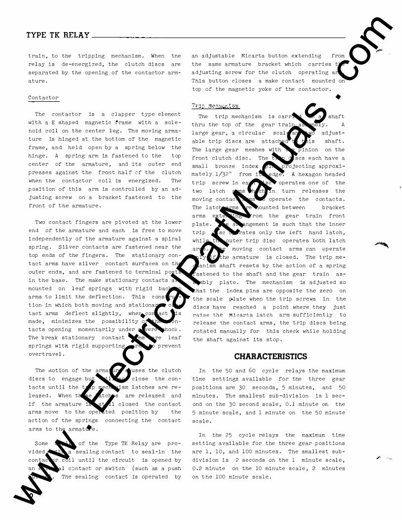
Contactor
The contactor is a clapper type element
with a E shaped magnetic frame with a sole
noid coil on the c enter leg . The moving arma
ture is hinged at the bottom of the magnetic
frame , and held open by a spring below the
hinge . A spring arm is fastened to the top
c enter of the armature , and its outer end
pre s s e s against the front half of the clutch
when the contactor coil is energized . The
position of thi s arm is controlled by an ad
justing screw on a bracket fastened to the
front of the armature .
Two contact fingers are pivoted at the lower
end of the armature and each is free to move
i ndependently of the armature against a spiral
spring . Silver contacts are fastened near the
top ends of the fingers . The stati onary con
tact arms have s ilver contact surfaces on the
outer end s , and are fastened to terminal posts
in the bas e . The make stati onary contacts are
mounted on leaf spring s with rigid back-up
arms to limit the deflection . Thi s c onstruc
tion in which both moving and stationary con
tact arms deflect slightly , when contact i s
made , minimizes the possibility of the con
tacts opening momentarily under severe shock.
The break stationary contact arms are leaf
springs with rigid supporting arms to prevent
overtravel .
The motion of the armature caus e s the clutch
di s c s to engage but will not clo se the con
tacts until the trip mechani sm latches are re
leased . When these latche s are released and
if the armature is still closed the contact
arms move to the operated position by the
acti on of the springs connecting the contact
arms to the armature .
Some styles of the Type TK Relay are pro
vided with a sealing c ontact to seal-in the
contactor coil until the circuit is opened by
an external contact or switch ( such as a push
button) . The sealing contact is operated by
2
an adjustable Mic arta button extending from
the same armature bracket which c arri es the
adjusting screw for the clutch operating arm .
Thi s button closes a make contact mounte d on
top of the magnetic yoke of the contactor .
Trip Mechani sm
The trip mechani sm i s carried on a shaft
thru the top of the gear train assembly . A
large gear , a circular scale and two adjust
able trip di s c s are attached to thi s shaft .
The large gear meshes with the pinion on the
front clutch disc . The trip di s c s e ach have a
small bronze index pin projecting approxi
mately l/32" from its edge . A hexagon headed
trip screw in each di sc operates one of the
two latch arms which in turn releases the
moving contact arms to operate the c ontacts .
The latch �rms are mounted between bracket
arms extending from the gear train front
plate . The arrangement is such that the inner
trip disc operate s only the left hand latch ,
while the outer trip disc operate s. both latch
arms . The moving contact arms can operate
only if the armature is close d . The trip me
chanism shaft resets by the action of a spring
fastened to the shaft and the gear train as
sembly plate . The mechani sm is adjusted so
that the index pins are oppos ite the zero on
the scale pJ.ate when the trip screws in the
discs have reached a point where the;y· just
raise the Micarta lat ch arm sufficiently to
release the contact arms , the trip di s c s being
rotated manually for thi s check while holding
the shaft against its stop .
CHARACTERISTICS
In the 50 and 60 cycle relays the maximum
time settings available for the three gear
pos itions are 30 seconds , 5 minutes , and 50
minute s . Th e smalle st sub-divi s ion i s 1 sec
ond on the 30 second s c ale , 0 . 1 minute on the
5 minute scale , and 1 minute on the 50 minute
scale .
In the 25 cycle relays the maximum time
s etting available for the three gear pos itions
are 1 , 10 , and 100 minutes . The smallest sub
divi sion i s 2 seconds on the l minute s c ale ,
0.2 minute on the 10 minute s c ale , 2 minutes
on the 100 minute scale .
www . El
ectric
alPar
tMan
uals
. com
TYPE TK RELAY
INTERNAL SCHEMATIC
CONTACTOR COIL
REAR VIEW
!"OPERATES FIRST IN SEQUENCE !·OPERATES NEXT I N SEQUENCE
FOR 230.V AND UP CONNECT TO TAP ON CONTACTOII cOIL
MOTOR
56-D-807
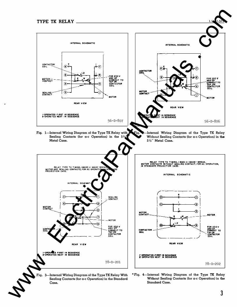
Fig. 1-lnternal Wiring Diagram of the Type TK Relay with Sealing Contacts (for a-c Operation) in the SV2" Metal Case.
RELAY TYPE TK TIMING, IMAKE + I MAKE-BREAK,
��J��c'\�gNs����r CONTACTS, FOR AC OPERATION, IN STANDARD
INTERNAL SCHEMATIC
MOTOR
REAR V I EW
!•OPERATES "RST IN SEQUENCE Z"OPEIIATES NEXT IN SEQUENCE
SEALING CONTACT
��� t1.0 v CONNECT TO TAP ON CONTACTOR COIL
78-D-201
Fig. 3---lnternal Wiring Diagram of the Type TK Relay With Sealing Contacts (for a-c Operation) in the Standard Case.
MOTOII CONTAGT
INTERNAL SCHEMATIC
REAli VIEW
I-OPERATES FIRST I N SEQUENCE z-oPERATES NEXT I N SEQUENCE
I. l. 41-574
56-D-806
Fig. 2-Internal Wiring Diagram of the Type TK Relay Without Sealing Contacts (for a-c. Operation) in the 5%" Metal Case.
RELAY TYPE TK T IMING, I MAKE+I MAKE- BREAK, �O��:Ng2�6A�;gJ�dWJl��:�:
.LING CONTACT, FOR AC OPER ATION,
MOTOR CONTACT
I N TERNAL SCHEMATI C
,---�� --, I® �I Q) !' i ® 1 ;: @
l�o�� fOil 230 V I
L __
r��lcT TO
IIEAII VIEW
t" OPERATES .fiiiST IN SEQUENCE �OPEIIATEI NEXT IN SEQUENCE
I
_ _/ TAP ON CONTACTOII COIL
78-D-202
*Fig. 4-Internal Wiring Diagram of the Type TK Relay Without Sealing Contacts (for a-c Operation) in the Standard Case.
3 www . El
ectric
alPar
tMan
uals
. com
TYPE TK RELAY ____________________________ ____________ ____ __
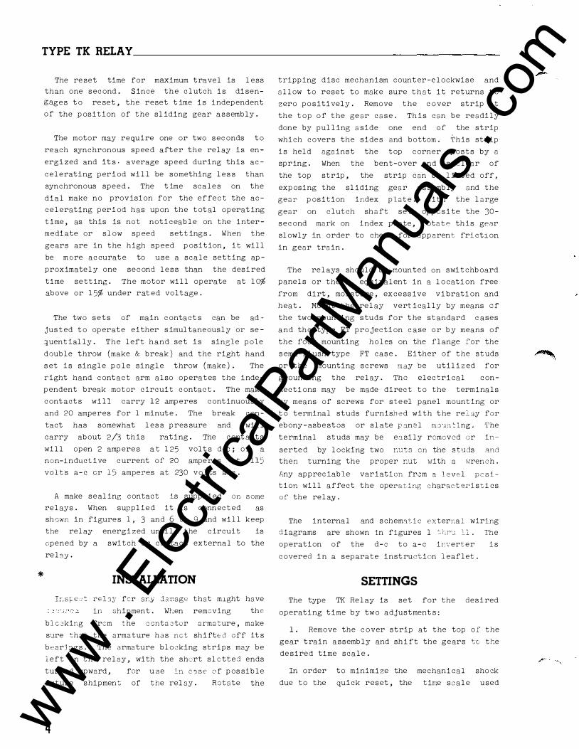
The re set time for maximum travel is less
than one second. Since the clutch is disengages to re set, the reset t ime is independent
of the position of the sliding gear assembly .
The motor may require one or two seconds to
reach synchronous spee d after the relay is en
ergized and it s- average speed during this ac
celerating period will be something les s than
synchronous speed . The time scale s on the
dial make no provision for the effect the ac
celerating period has upon the tot al operating
time, as this is not noticeable on the inter
mediate or slow speed settings . When the
gears are in the high speed position, it will
be more accurat e to use a scale setting ap
proximately one second le s s than the desired
time setting . The motor will operate at 10%
above or 15% under rated voltage .
The two sets of main contact s can be ad"
justed to operate either simultaneously or se
�uentially . The left hand set is sin3le pole
double throw (make & break ) and the right hand
s et is single pole single throw ( make ) . The
right hand contact arm also operates the inde
pendent break motor circuit contact . The make
cont act s will carry 12 amperes continuously
and 20 amperes for 1 minut e . The break con
tact has somewhat les s pres sure and will
carry about 2/3 this rating . The cont acts
will open 2 ampere s at 125 volt s d-e; or a
non-inductive current of 20 amperes at 115
volts a-c or 15 amperes at 230 volts a-c.
*
A make sealing contact is supplied on some
relays . When supplied it is connected as
shown in figures 1, 3 and 6 to 9 and will keep
the relay energized until the circuit is
opened by a switch or contact external to the
rel:oy.
INSTALLATION
!Ls�e�t relay fer a�y damage that m1ght have
in shipment . Wr:en removing the
blc2king frcm the contactor armature, make
sure that the armature has net shifted off it s
bearjngs . The armature blocking strips may be
left in the relay, with the short slotted ends
turned upward, for use in CJSE' of pos sible
future shipment of the relay .
4
Rotate the
tripping disc mechanism count er-clockwise and
allow to reset to make sure that it returns to
zero positively. Remove the cover strip at
the top of the gear case. This can be readily
done by pulling aside one end of the strip
which covers the side s and bottom. This strip
is held against the top corner posts by a
spring . When the bent-over end is clear of
the top strip, the strip can be lift ed off,
exposing the sliding gear as sembly and the
gear position index plate . With the large
gear on clutch shaft set opposite the 30 -
second mark on index plate, rotate this gear
slowly in order to check for apparent frict1on
in gear train.
The relays should be mounted on switchboard
panels or their equivalent in a location free
from dirt, moisture , exce ssive vibration and
heat . Mount the relay vertically by means of
the two mounting studs for the standard cases
and the type FT projection case or by means of
the four mounting holes on the flange for the
s emi-flush type FT case . Either of the studs
or the mounting screws may be utilized for
grounding the relay . Tho electrical con
nections may be made direct to the terminals
by means of screws for ste el panel mounting or
to terminal studs furnished with the rec.ay for
ebony-asbe stos or slate panel rrLJJ.n7: Lng. The
terminal studs may be easily removed cr in-·
serted by locking two nuts en the studs and then turning the proper nut with a wrench .
Any appreciable variation from a level position will affect the operating characteristics
of the relay.
The internal and schematic external wiring
diagrams are shown in figures 1 '�Lr'-.: ll. The
operation of the d-e to a-c inverter is
covered in a separate inst ruction leaflet.
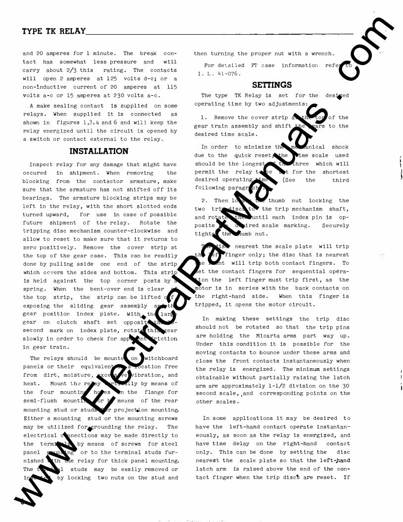
SETTINGS
The type TK Relay is set for the desired
operating time by two adjustment s:
1. Remove the cover strip at the top of the
gear train assembly and shift the gears tc the
de sired time scale .
In order to minimize the mechanical shock
due to the quick reset, the time scale used
www . El
ectric
alPar
tMan
uals
. com
TYPE TK RELAY ________________________________________________ �t�L�4�1 -�57�4
CONTACT COIL
MOTOR CONTACT
INTERNAL SCHEMATI C
M
@�------\r�--�
REAR VIEW
OTOR
I-OPERAT ES FIRST IN SEQUENCE 2-0PERATES NEXT IN SEQUENCE I
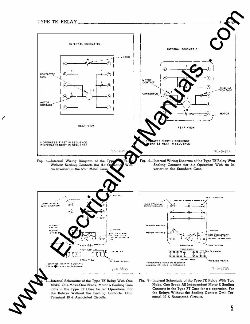
L----------------� Fig. 5-lnternal Wiring Diagram of the Type TK Relay
Without Sealing Contacts (for d-e Operation With an Inverter) in the SV2" Metal Case_
TE.ST &WITCH 1 ! I I I I I I n-TO R�'"'y c_::=-.=::__:__:::_•R_o_"_T _\J_I__:�w=-=-=--=:;. --�
\ ()f"E.RA"TE.S F\RS"t IN S EQVE.NC..E 2. OPERATES N.E..XT IN. SE.QUENC.E
To BASE "TERM.:!
'7-D-6699 L--------------------------------------------------�
Fig. 7-lnternal Schematic _of the Type TK Relay With One Make. One-Make-One Break. Motor & Sealing Contacts in the Type FT Case for a-c Operation. For the Relays Without the Sealing Contacts, Omit Terminal 10 & Associated Circuits.
MOTOR CONTACT
INTERNAL SCHEMATIC
REAR VIEW
I-OPERATES FIRST IN SEQUENCE 2-0PERATES NEXT IN SEQUENCE
78-D-214 I '--------------------------,-·
Fig_ 6-lnternal Wiring Diagram of the Type TK Relay With Sealing Contacts (for d-e Operation With an Inverter) in the Standard Case.
TEST SWI"TCH /'y---------� CO'JE� OPEAA1"��- ( � J 2 A , SWIOCH WHEN USEO
I ®,:X II
X ' I c ' 8 ' ®)I II X<»·
l@x 1r x®l 5EACIN& CONTACT, ! i � I MOTOR MOTOR CONTAC.T��M : FOR 230V, AND UP
1 ....... .� r H CONNECT TO TAP
�-� � '�,. , ONCONTAC.TOR COIC
REAR VtEW CONTAC.TOR.
FRONT VIEW
I-OPERATES FIRST IN SEQUE.Nc.£. 2.-0PERATE:S NE)(T IN SEQUENCE
TO BASE. T�RM.
7-D-6703 �---------------------------------- ----� Fig. 8-lnternal Schematic of the Type TK Relay With Two
Make. One Break All Independent Motor & Sealing Contacts in the Type FT Case for a-c operation. For the Relays Without the Sealing Contact Omit Terminal 10 & Associated C:ircuits.
5 www . El
ectric
alPar
tMan
uals
. com
TYPE TK RELAY
MOTOFI CONTACT
FRONT \IIEW 1- OPaRATES FIRST IN �l!qVI!NC..e:
2:- 0Pe.RATIL:5o SCCDND IN SEQ�NC.W.
_MOTOR
FOR Z�OV. AND UP C.ONNIECT TO TAP ON C.ONTACI"'R COIL
SHAFT CONTACT CLOSI!D WHEN. CAMS R'RE: Re.�£.'T.
TO RELAY
'Tl:) BA�E TERM.
7-D-6704
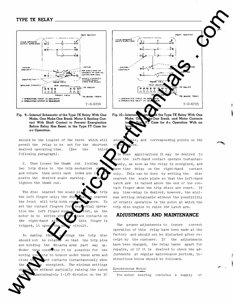
Fig. 9-Internal Schematic of the Type TK Relay With One Make, One Make-One Break, Motor & Sealing Contact With Shaft Contact to Prevent Energization Before Relay Has Reset, in the Type FT Case for a-c Operation.
should be the longest of the three which will
permit the relay to be set for the shortest
desired operating time . (See the third
following paragraph) .
2 . Then loosen the thumb nut locking the
two trip di s c s to the trip mechani sm shaft,
and rotate them until each index pin i s op-
posite the de sired scale marking .
tighten the thumb nut .
Securely
The disc nearest the scale plate will trip
the left finger only; the disc that is nearest
the front will trip both contact fingers. To
set the contact fingers for sequential opera
tion the left finger must trip first, as the
motor is in s eries with the back contacts on
the right-hand s ide. When thi s finger i s
tripped, it opens the motor circuit.
In making these s ettings the trip disc
should not be rotated so that the trip pins
are holding the Mi carta arms part way up .
Under thi s condition it i s possible for the
moving contacts to bounce under these arms and
close the front c ontacts instantaneously when
the relay i s energized. The minimum sett ings
obtainable without partially raising the latch
arm are approximat el3r 1-1/2 divi,sion on the 30
6
MOTOR CONTACT
I· OPERATES FIRST IN SEQUE.NCE
z.-OPERATES NEXT IN SEQUE�E
SWITCH
'"fb REl..AY
't'O BASE TI!.�M.
7 -D-6705
Fig. 10-Internal Schematic of the Type TK Relay With One Make, One Make-One Break. and Motor Contacts in the Type FT Case for d-e Operation With an Inverter.
second s cale, and c orre sponding points on the
other scales .
In s ome applications it may be desired to
have the left-hand contac t operate instantan
eously, as soon as the relay i s energized, and
have time delay on the right-hand c ontact
only . Thi s can be done by setting the disc
nearest the scale plate s o that the left -hand
latch arm i s rai sed above the end of the c on
tact finger wh en the trip di s c s are reset . If any time -delay i s desired , however, the mini
mum setting obtainable without the pos sibility
of erratic operation is the point at which the
trip di sc begins to rais e the latch arm .
ADJUSTMENTS AND MAINTENANCE
The proper ad justment s to insure c orrect
operat ion of this relay have been made at the
factory
c eipt by
and should not be disturbed after re-
the customer . If the adjustments
have been changed, the relay taken apart for
repairs, or if it is desired to check the ad
justments at regular maintenance periods, in
struct ions below should be followed .
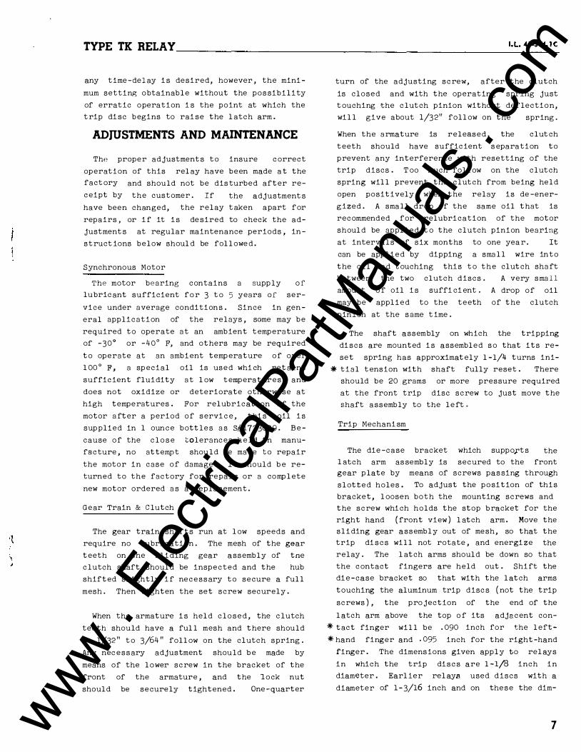
Synchronous Motor
The motor bearing contain s a supply of
www . El
ectric
alPar
tMan
uals
. com
I '
TYPE TK RELAY _________________________________________________ t=L�41�-5�74
lubricant sufficient for s everal years of s er
vice under average conditions . Since in gen
eral application of the relays, some may cre
required to opera t e at an ambient temperature
of -30� or -40° F, and others may be required
to operate at an ambient t emperature of over
100° F, a special oil is used which retain s
sufficient fluidity at low temperatures and
does not oxidize or deteriorate otherwise at
high temperatures . For relubrication of the
motor after a period of service, this oil is
supplied in 1 ounce bottles as 8#1723639 . Be
cause of the close tolerances held in manu
facture, no attempt should be made to repair
the motor in ca se of damage . It should be re
turned to the factory for repair or a complete
new motor ordered as a replacement .
Gear Train & Clutch
The gear train shafts run at low speeds and
require no lubrication . The mesh of the gear
t eeth on the sliding gear a s sembly of tne
clutch shaft should be inspected and the hub
shifted slightly if neces sary to secure a full
mesh . Then tighten the set screw securely.
When the armature is held clo sed, the clutch
t eeth should have a full mesh and there should
be 1/32 " to 3/64 " falloN on the clutch spring .
Any necessary adjustment should be made by
means of the lower screw in the bracket of the
front of the armature, and the lock nut
should be securely tightened . One -quarter
turn of the adjusting screw, after the clutch
i s closed and with the operating spring just
touching the clutch pinion without deflection,
will give about 1/32 " follow on the spring .
When the armature is relea sed, the clutch
teeth should have sufficient s eparation to
prevent any interference with resetting of the
trip discs . Too m·�ch follow on the clutch
spring will prevent the clutch from being held
open positively when the relay is de-ener
gized .
If the relay operates very frequently, re
mains energized for long periods, or is in
stalled where the ambient temperature is high,
a small drop of the same oil that is recom
mended for relubrication of the motor should
be applied to the clutch pinion bearing at in-
EXTERN-'L CONNE-CTIONS F"oR 0- C OPERATION
D·C+-.----------------------------------0-C--r-----------------------------.-
POTENTIOMET ER FoR 250 VOLTS D-C
EXTERNAL CONNECTIONS FoR A-C OPE-RATION
A·C
A·C
MOTOR.
23-D-9477
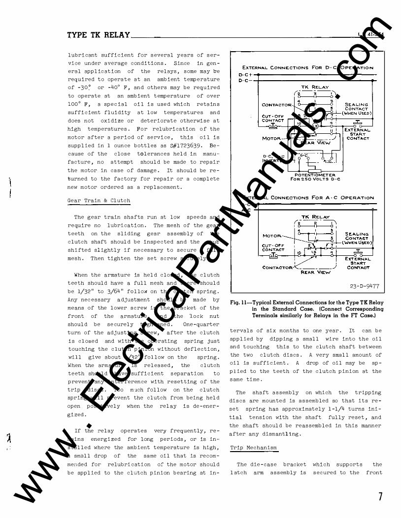
Fig. 1 1-Typical External Connections for the Type TK Relay in the Standard Case. (Connect Corresponding Terminals similarly for Relays in the FT Case.)
tervals of six months to one year . It can be
applied by dipping a small wire into the oil
and touching this to the clutch shaft between
the two clutch discs . A very small amount of
oil is sufficient . A drop of oil may be ap
plied to the t eeth of the clutch pinion at the
s ame time.
The shaft a s sembly on which the tripping
discs are mounted is a s sembled so that it s re
set spring has approximately 1 -1/4 turns ini
tial tension with the shaft fully reset, and
the shaft should be reas sembled in this manner
after any dismantling .
Trip Mechanism
The die -case bracket which support s the
l atch arm a s sembly is s ecured to the front
7 www . El
ectric
alPar
tMan
uals
. com
TYPE TK RELAY ______________________ _
gear plate by means of screws passing through
slotted holes . To adjust the position of this
bracket, l oosen both the mounting screws and
the screw which holds the stop bracket for the
right hand (front view) l atch arm . Move the
sliding gear assembly out of mesh, so that the
trip discs will not rotate, and energize the
relay . The l atch arms should be down so that
the contact fingers are held out . Shift the
die-case bracket so that with the latch arms
touching the aluminum trip discs (not the trip
screws), the pro jection of the end of the
latch arm ab ove the top of its adjacent con
tact finger will be .075 inch for the l eft
hand finger and .070 inch for the right-hand
finger . The dimensions given apply to relays
in which the trip discs are l - l/8 inch in
diameter. E arL· er relays used discs with a
diameter of l-3/16 inch and on these the dim
ensions shoul d be .010 inch for the left-hand
finger and .120 inch for the right-hand
finger . A small strip of metal with the ends
filed to these dimensions will be convenient
to use as a gauge. It can be rested on the
ends of the contact fingers and the bracket
shifte d until the upper front corners of the
fingers are even with the ends
The mounting screws for the
of the gauge .
bracket should
then be tightened securely. The screw for the
right-hand latch arm stop bracket shoul d be
tightened and the bracket should be bent up or
down until the latch arms just clear the small
bronze index pins projecting from the trip
disc .
Raise the right-hand latch with the fingers
and move the armature in by hand until the
tips of the contact fingers are opposite the
l owest portions of the l atch arms . When the
l eft-hand latch arm is just touching its con
tact finger, there shoul d be a gap of about
.010" to .015 inch b etween the right-hand arm
and its contact finger . (This relation be
tween the latches and the contact fingers pre
vents any possibility of the l eft-hand finger
tripping first when the trip discs are set for
simultaneous tripping) .
Loosen the thumb nut locking the two trip
discs and energize
still out of mesh .
the relay with the gears
Hold the final gear firmly
against its back stop, and rotate each trip
disc by hand until it depresses its l atch arm
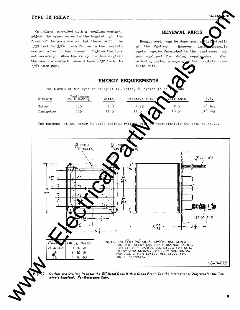
�DRILL (2 HOLES) M DRILL (liS REQUIRED)
i ln
I" I-
'
T --
f\J +- ( -.."''1 -"'"' -lt-1-+-t-T_c I
NO. OF f£RMINALS 8 OR LESS
!0
DRILL HoLEs I TO 8
I T0 9 I TO 10 - - --
r-l�",l]a ! I I
I. 190-3ZITH'D. 5 29
32 I
-+--< 2 3 -1 4
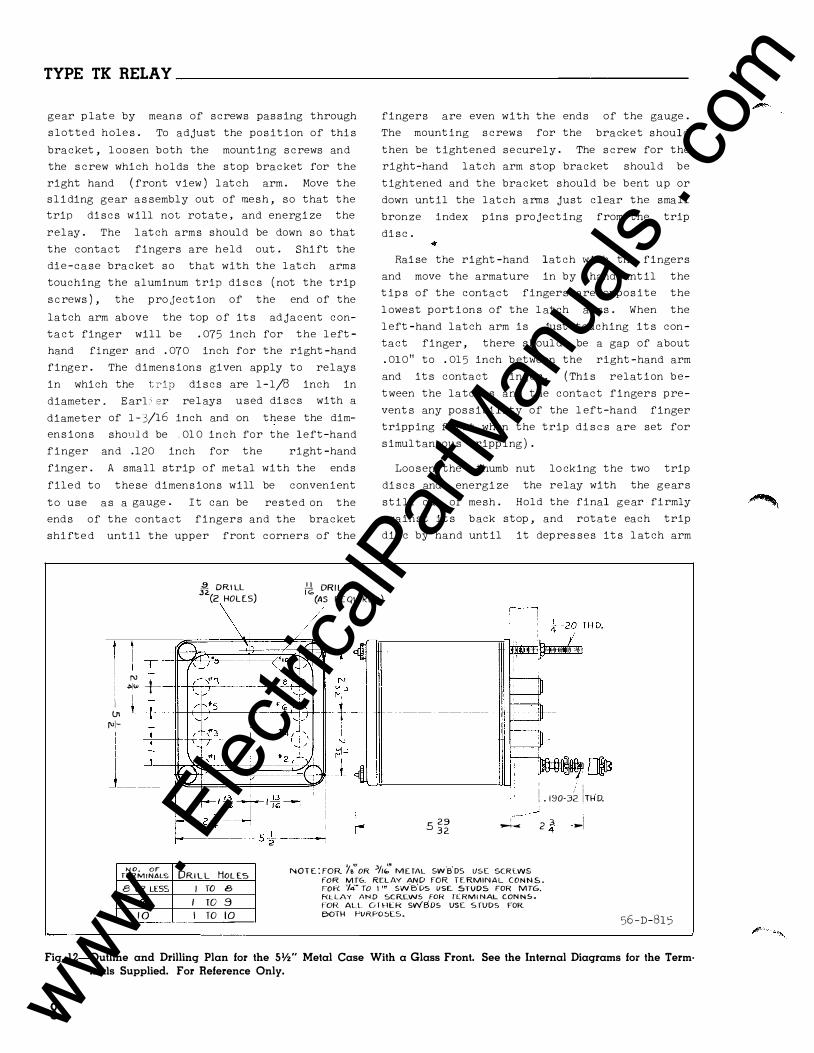
NOTE: FOR'/�" OR 3/i/.." METAL sw'B'Ds IJSE SCRLWS fOR MTG. RELAY AND fOR TERMINAL CONNS. FOR '/4" TO I'" sw'B'Ds USE. STUDS FOR MTG, f<LLAY AND SCRCW5 FOR lTRMINAL CONNS.
fOR ALL 0 I HER SWBDS USE S fUD5 FOR e>OTH PURPOSES.
56-D-1315
Fig. 1 2-0utline and Drilling Plan for the Slf2" Metal Case With a Glass Front. See the Internal Diagrams for the Term· inals Supplied. For Reference Only.
8 www . El
ectric
alPar
tMan
uals
. com
TYPE TK RELAY------------------------------------------------�'·=L-41�-5� 74
OPENING; FOR fHIN PANEL MTGi.
t DIA.DRILL_;
r--------7 jh------- ···1 USE SCREWS FOR THIN PANELS
r-----
-------1 I USE STU D S FOR TH I C K PANELS
I
----------IJ.._jl -- -
'-- � DIA. DRILL 32 (2-HOLES)
.1�0-32 TERM SCRLWS 1:i STUDS -41 -zo M O U N T IN(1 SC R E W S
& STUDS
DIMENSIONS IN INCHE.S
t-� J --2��� 63-D-301
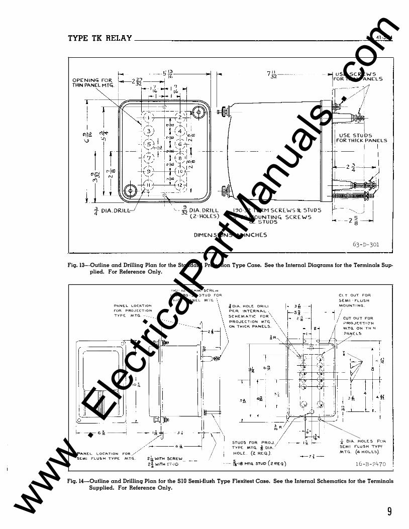
Fiq. 13-0utline and Drillinq Plan for the Standard Projection Type Case. See the Internal Diaqrams for the Terminals Supplied. For Reference Only.
PJI...NE.L LOC_A.l\ON FOR PROJECTION TYPE MTG. -
0
�� oo' LJ �
J I I jJ f---- 6 (.; ----1
1'::1'()- :s.C:. rE.KM. SCRt.vv U.Sc l9Q -.32. 5TUD FOR ThiCK PANEL M-IG.
t='Pt\NEL LOCATION FOR SE.M\ FLUSH "TYPE MTG.. zi., WITH SCREW_ 2i W1TH �T•iD
� OIA.. HOLE. DRIL\ PER INTERN!'.L
SCHEMATIC FOR
PROJECTION MT� ON THICK PANELS.
�R.
9�
STUDS FOR PROJ.
TYPE MTCO. i DIA. HOLE.. (i! RteQ.). rs-18 HT<';. STUD ( 2 RE q.)
ClT OUT FOR
5EMI- FLUSH
MOUNTING.
CUT OUT FOR
TH't-t
�� * DIA. HOLES FOR SEMI FLUSH TYPF MTG. (4 HOLES) .
16-B-?470
Fiq. 14-0utline and Drillinq Plan for the SlO Semi-flush Type Flexitest Case. See the Internal Schematics for the Terminals Supplied. For Reference Only.
9 www . El
ectric
alPar
tMan
uals
. com
TYPE TK RELAY-----------------------
far enough to just trip the c ontact finger.
The bronze pin pro ject ing from each trip di sc
serves as its zero index, and should be op
posite the zero on the dial when the contact
finger trips. The trip screws are prevented
from turning by a locking wire spring which
passes through a slot in the inner end of the
trip screw and is ac cessible from the rear of
the trip di sc. It should be moved out of the
slot, and the trip screw shou ld be screwed in
or out until the index pin is opposite the
zero on the dial when the contact finger is
released. Then the locking spring shoul d be
placed in the slot of it s trip screw to pre
vent any accidental change in adjustment . The
trip discs shoul d release the contact fingers
when the trip screws are one scale division or
more from the center or lowe st position.
Repeated tests have shown that the rel ay
wi ll make more than one million operations b e
fore the striking and rubbing action of the
contact fingers on the ends of the latch arms
wears them sufficiently to require replace
ment.
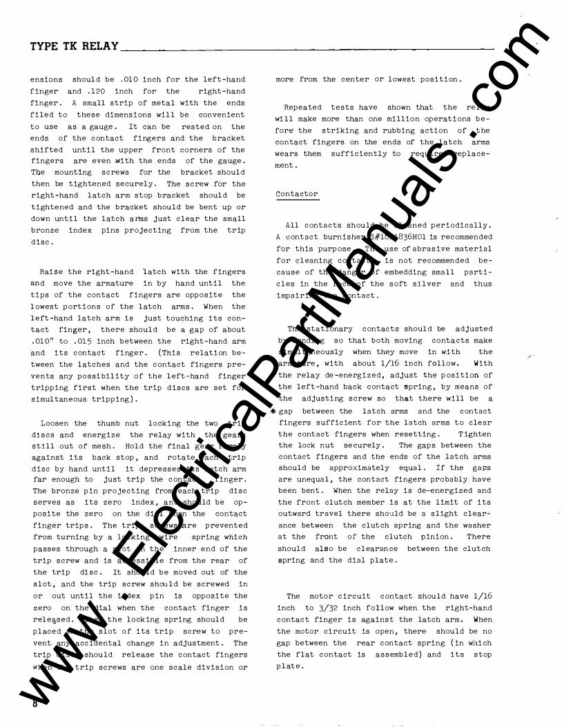
Contactor
All contacts shoul d be periodically cleaned
with a fine file . S#l 00211 0 file is recom
mended for thi s purpose. The use of abrasive
material for cleaning contacts is not recom
mended because of the danger of embedding
smal l part icles in the face of the soft silver
and thus impairing the contact .
The stationary contac ts shoul d be adjusted
by bending so that both moving contacts make
simultaneously when they move in with the
armature, with about 1/16 inch follow . With
the relay de -energized, adjust the position of
the left -hand back contact spring, by means of
the adjusting screw so that there will be a
gap of 1/64 inch or sl ightly more, between the
ends of the latch arms and the contact
fingers. Tighten the lock nut securely . The
gaps between the contact fingers and the ends
of the latch arms should be approximately
equal. If the gaps are unequal, the contact
fingers probably have been bent . When the re
lay is de -energized and the front clutch mem
ber i s at the limit of its outward travel
there should be a slight clearance between the
clutch spring and the washer at the front of
the clutch pinion . There should also be
clearance between the clutch spring and the
dial plate.
The motor c ircuit contact should have 1/16
inch to 3/32 inch follow when the right-hand
contact finger i s against the latch arm . When
the motor circuit i s open, there should b e no
gap between the rear contact spring ( in whi ch
the flat contact i s assembled) and its stop
plat e .
On relays provided with a sealing contact,
adjust the upp er screw in the bracket at the
front of the armature so that there will be
1 /32 inch to 3/64 inch follow in the seal-in
contact after it has closed. Tighten the lock
nut securely. When the relay is de -energized
the seal -in contact shoul d have 1/32 inch to 3/64 inch gap.
RENEWAL PARTS
Repair work can be done most satisfactorily
at the factory . However, interchangeable
parts can be furnished to the customers who
are equipped for doing repair work. When
ordering part s, always give the complete name
plate data.
ENERGY REQUIREMENTS
10
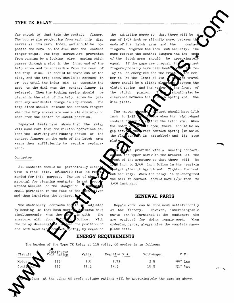
The burden of the Type TK Relay at 1 1 5 volts, 60 cycles is as fol lows :
Circuit
Motor
C ontactor
Continuous Volt Rating
115
1 1 5
Watts
1 . 8
1 1 .5
Reactive V.A.
1 .73
14 . 5
Volt-Amps.
2.5
18.5
P. F.
44 ° Lag
51 ° Lag
The burdens at the other 60 cycle voltage ratings will be approximately the same as above.
-
www . El
ectric
alPar
tMan
uals
. com

www . El
ectric
alPar
tMan
uals
. com
WESTINGHOUSE METER DIVISION
ELECTRIC •
CORPORATION NEWARK, N.J.
Printad in U. S. A. www . El
ectric
alPar
tMan
uals
. com
�'
INSTALLATION •
Westinghouse J.L. 41-574.1 c OPERATION • MAINTENANCE
INSTRUCTIONS TYPE TK TIMING RELAY
CAUTION Before putting relays into service,
remove all blocking which may have been in
s erted for the purpose of securing the p arts
during shipment, make sure that all moving
p arts operate freely, inspect the contacts to
see that they are clean and close properly,
and operate the relay to check the settings
and electrical connections .
APPLICATION
The Type TK Relay is an a-c timing relay for
applications requiring a definite time delay
between the cl osing of an a-c circuit and the
closing or opening of other d-e or a-c cir-
cuits. Accurate time-settings from two sec-
onds to fifty minutes can be obtained, and,
for any setting, the reset time is les s than
one second.
The relay is used where t ime delay is re
quired in motor , generator, or rectifier con
trol circuit s. It is also widely used in in
dustrial applications .
One type of the relay i s available for use
with a d-e to a-c inverter where a reliable
a-c control voltage i s not available . The in
verter is des cribed in I . L . 41 -856 .
CONSTRUCTION AND OPERATION
The type TK relay consi sts of a synchronous
motor, a gear train to provide three different
ratios, a clutch interposed in the gear train
to permit quick resetting when the relay is
de-energized, a contactor which carries the
main contacts and operates the clutch, and a
tripping mechanism adjustable for time-delay.
SUPERSEDES I.L. 41-574.18 *Denotes change from superseded issue.
Synchronous Motor
The motor for driving the gear train i s
located o n the back plate of the gear train
assembly in the l ower right-hand corner . It
runs at a synchronous speed of 600, 500 or 250 R .P . M . for 60, 50 or 25 cycle relays re
spectively . Its bearing has an oil reservoir
with sufficient capacity for several years of
normal operation. On relays rated at 230 or
higher, the contactor coil has a tap brought
out at the propc� place to act as an auto
transformer to supply 115 volts for the motor.
Gear Train and Clutch
The gear train is assembled as a separate
unit and consists of two brass bearing plates
fastened together at the corners by brass
posts. The gear shafts run at low speeds and
require no lubrication. The three different
speeds are obtained by changing the location
of a sliding gear as sembly . Thi s assembly
consists of two gears on a hub that i s free to
s lide on the clutch shaft and can be l ocked in
any desired position with a set screw. The
hub is moved to the position where the larger
gear i s opposite the arrow on the index plate-- __ �--
corresponding to the desired time scale.
The clutch i s two aluminum disc with ser
rated faces, arranged so that they are posi
tively engaged and disengaged by a spring arm
on the contactor armature when the latter i s
in its closed and open positions respectivel y .
The rear disc i s fastened t o a shaft o n the
gear train . The front disc i s a running fit
on the end of the same shaft. The latter disc
has fastened to it the p inion which drives the
tripping mechanism . When the relay i s ener
gized, the clutch discs engage and power is
transmitted from the motor, through the gear
EFFECTIVE MAY 1961
www . El
ectric
alPar
tMan
uals
. com
TYPE TK RELAY-----------------------
train, t o the tripping mechanism. When the
relay i s de-energized, the clutch di scs are
separated by the opening of the contactor arm
ature .
Contact or
The cont actor i s a clapper type element
with a E shaped magnetic frame with a sole
noid coil on the center leg . The moving arma
ture is hinged at the bottom of the magnet ic
frame, and held open by a spring below the
hinge . A spring arm is fastened to the t op
center of the armature, and its outer end
presses against the front half of the clutch
when the contactor coil i s energized. The
position of this arm i s controlled by an ad
justing screw on a bracket fastened to the
front of the armature .
Two contact fingers are pivoted at the l ower
end of the armature and each i s free to move
independently of the armature against a spiral
spring . Silver contacts are fastened near the
top ends of the fingers . The stationary con
tact arms have s ilver contact surfaces on the
outer ends, and are fastened to terminal posts
in the base . The make stati onary contacts are
mounte d on l eaf spring s with rigid back-up
arms to l imit the deflection . Thi s construc
tion in which both moving and stationary con
tact arms deflect slightly, when contact is
made, minimizes the poss ibility of the con
tact s opening momentarily under severe shock .
The break stationary contact arms are l eaf
springs with rigid supporting
overtravel .
arms to prevent
The motion of the armature causes the clutch
an adju�table Micarta button extending from
the same armature bracket which carries the
adjusting screw for the clutch operating arm .
Thi s button closes a make contact mounted on
top of the magnetic yoke of the contactor .
Trip Mechanism
The trip mechanism is carried on a shaft
thru the t op of the gear train assembly . A
large gear, a circular scale and two adjust
able trip discs are attached to this shaft .
The large gear meshes with the pinion on the
front clutch disc . The trip discs each have a
small bronze index pin pro jecting approxi
mately 1/32" from its e dge . A hexagon headed
trip screw in each disc operates one of the
two latch arms which in turn releases the
moving contact arms to operate the contact s .
The latch 8rms are mounted between bracket
arms extending from the gear train front
plate . The arrangement i s such that the inner
trip disc operates only the l eft hand latch,
while the outer trip disc operates both latch
arms . The moving contact arms can operate
only if the armature is closed . The trip me
chanism shaft resets by the action of a spring
fastened to the shaft and the gear train as
sembly plate . The mechanism i s adjusted so
that the index pins are opposite the zero on
the scale plate when the trip screws in the
discs have reached a point where they just
raise the Micarta latch arm sufficiently to
release the contact arms , the trip discs being
rotated manually for this check while holding
the shaft against its stop .
CHARACTERISTICS
discs to engage but wil l not close the con- * In the 50 and 60 cycle relays the time set
tacts until the trip mechanism l atches are re - tings available for the three gear positions
leased . When these latches are released and
if the armature is still closed the contact
arms move to the operated position by the
action of the spring s connecting the contact
arms to the armature.
Some styles of the Type TK Relay are pro
vided with a s ealing contact to seal-in the
contactor coil until the circuit is opened by
an external contact or switch ( such as a push
button ) . The sealing contact is operated by
2
are:
Minimum
2 S ec .
. 3 Min .
3 Min .
The smallest sub -division
Maximum
30 Sec o
5 Min .
50 Min .
i s 1 second on
the 30 s econd scale, O . l minute on the 5 minute
scale, and 1 minute on the 50 minute s cale.
www . El
ectric
alPar
tMan
uals
. com
TYPE TK BELAY
NOTE:
10PERATESFIRSTINSEQUEHCE 2 OPERATES IIEXT Ill SEQUEMCE
INTERNAL SCHEMATIC
FRONT VIEW
CONTACTORUJIIIT
TUtER UNIT
FOR 230 Y. AND UP, CONNECT TO TAP ON COW TACTOR COil
TEST SWITCH
TERMINAL
57-D-7909
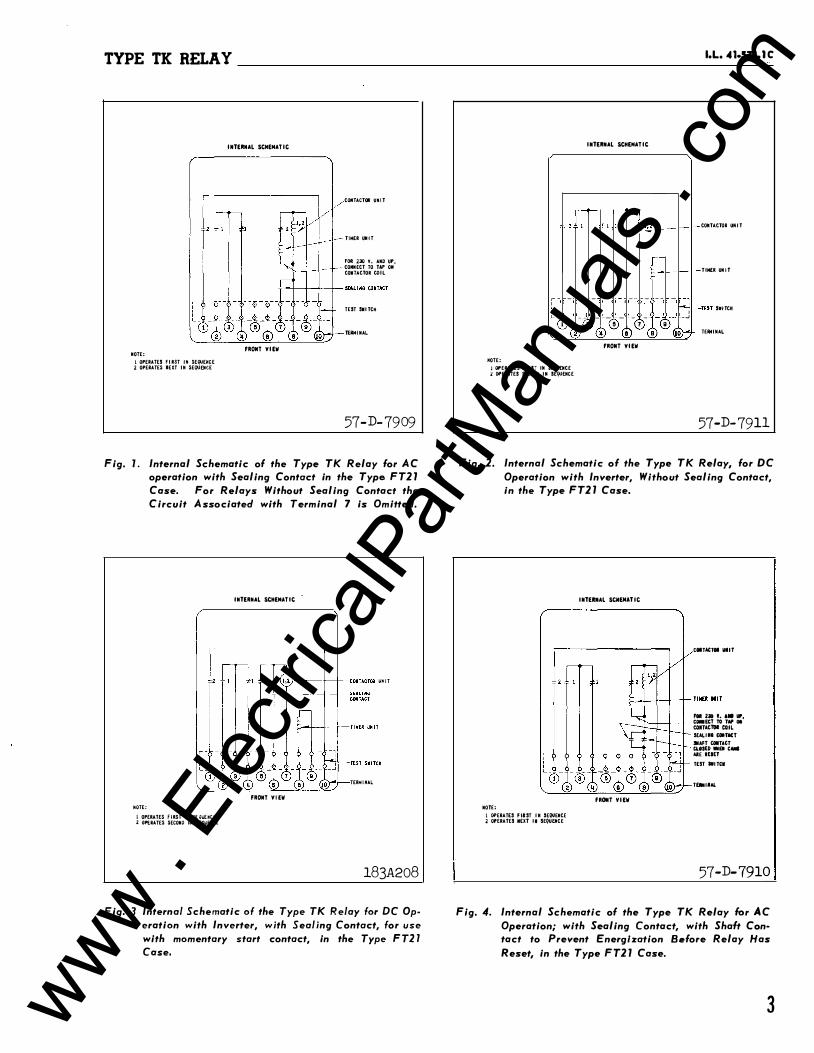
Fig. l. Internal Schematic of the Type TK Relay for AC operation with Sealing Contact in the Type FT21 Case. For Relays Without Sealing Contact the Circuit Associated with Terminal 7 is Omitted.
NOTE:
1 OPERATES fiRST Ill SE(}UUCE 20PERATES SECOND INSEQIJEIICE
INTERNAL SCHEMATIC
.}-�-f--+�tOJITACTOR LIMIT
TERNIMAL
FRONT VIEW
183A208
Fig. 3 Internal Schematic of the Type TK Relay for DC Operation with Inverter, with Sealing Contact, for use with momentary start contact, in the Type FT21 Case.
INTERNAL SCHEMATIC
,[� ,-<� 1 ' '·' - �
,-
, - - -- - � -- - -- � _.J ' �- - ---- � � - - � -- _j
1 3 !5 7 g C� C0 <!:> 0 �
MOTE:
1 OPERATES FIIIS7 Ill SEQUENCE l OPERATES SECOND IN SEQOENCE
FRONT VIEW
I.L. 41·574.1 C
COIITACTORUIIIT
TIMfR UNIT
-· TEST SWITCH
,__ TERMINAL
57-D-7911
Fig. 2. Internal Schematic of the Type TK Relay, for DC Operation with Inverter, Without Sealing Contact, in the Type FT21 Case.
NOTE:
1 OPERATES FIIST IN SEQUENCE 2 OPERATES N£XT Ill SEQUEMCE
INTEIUIAL SCIIEIIATIC
FRONT VIEW
COITACTOI UIIT
FOil 230 ..... W', 1'--+--+----,1- ��:�TOe:� 01 SfAL 1111 COITICT
JNAFT COITACT CLOSED IIEI CMII AlE IEIET TEST IIITCI
T�IIAL
57-D-7910
Fig. 4. Internal Schematic of the Type TK Relay for AC Operation; with Sealing Contact, with Shalt Con· tact to Prevent Energlzation Before Relay Has Reset, in the Type FT21 Case.
3 www . El
ectric
alPar
tMan
uals
. com
TYPE TK RELAY ________________ ____________________ ____________ _
In the 25 cycle relays the maximum time
setting available for the three gear positions
are 1, 10, and 100 minutes. The smallest sub
division is 2 seconds on the 1 minute scal e ,
0.2 minute on the 10 minute scale , 2 minutes
on the 100 minute scale.
The re set time for maximum travel is les s
than one second . Since the clutch is disengages to re set, the res et time is independent
of the position of the sliding gear as sembly .
The motor may require one o r two s econds to
reach synchronous speed after the relay is en
ergized and its average speed during this ac
celerating period will be something l e s s than
synchronous speed. The time scale s on the
dial make no provi sion for the effect the ac
celerating p eriod has upon the total operating
time , as thi s i s not noticeable on the inter
mediate or slow speed settings. When the
gears are in the high speed position, it will
be more accurate to use a scale setting ap
proximately one second le ss than the desired
time setting. The motor will operate at lo% above or 1 5% under rated voltage .
The two sets o f main contacts can be ad
justed to operate either s imultaneously or s e
:J_uentially . The l eft hand s et is single pole
double throw (make & break ) and the right hand
CONTA'GTOR COIL �
SEALING CONTAC T
REAR VIEW
!·OPERATES FIRST IN SEQUENCE 2-0PERATES NEXT I N SEQUENCE
__ FOR 230 V AND UP CONNECT TO TAP ON CONTACTOR COIL
� MOTOR
56-D-807
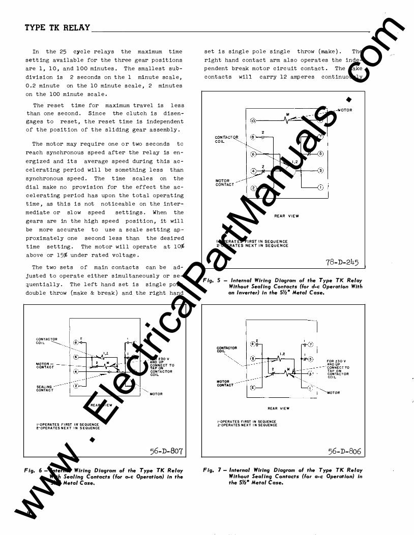
Fig. 6- Internal Wiring Diagram of the Type TK Relay With Sealing Contacts (for a•C OperatioiJ) in the s12• Metal Case.
4
set i s single pole s ingle throw (make ) . The
right hand contact arm als o operates the inde
pendent break motor circuit contact. The make
contacts will carry 12 amp eres continuously
MOTOR CONTACT
M
@J-----''v�---<
REAR VIEW
I-OPERATES FIRST IN SEQUENCE z-OPERATES NEXT IN SEQUENCE
OTOR
78-D-245
Fig. 5 - Internal Wiring Diagram of the Type TK Relay Without Sealing Contacts (for d-e Operation With an Inverter) in the s12• Metal Case.
CONTACTOR COIL � MOTOR CONTACT
REAR VIEW
I-OPERATES FIRST IN SEQUENCE 2-0PERATES NEXT IN SEQUENCE
FOR 230 V AND UP CONNECT TO TAP O N CONTACT OR COIL
�MOTOR
56-D-806
Fig. 7- Internal Wiring Diagram of the Type TK Relay Without Sealing Contacts (for a•c Operation) in the SJ2• Metal Case.
www . El
ectric
alPar
tMan
uals
. com
TYPE TK RELAY __________________________________________________ ,.L_._4 _t-s_� __ tc
AC OPERATION WITH SEALING CONTACT
''-+--�------------
POS. OR II£ G.
CUT-OFF COM TACT
2 ciiii
EXTERNAL START SWI TCK�
" POTUT IOMETER
P��Q. OR _j__
TO COlt TROLLED CIRCUITS
TO COtil'ROLLEO CIRCUITS
DC OPER'ATION �ITH SEALING CONTACT
DEYICf HUMBER CitART 2•TtNINGREU.'f'T't'PETit
t-NOTOR
�-COMTACTOR st- SULIIIO CONTACT
1C - COHTACT OPERATES fiRST UISEQUEIICE
2C -COMTACT OPERATES SECOHO IM SEQUENCE
TO CONTROLlED
CIRCUITS
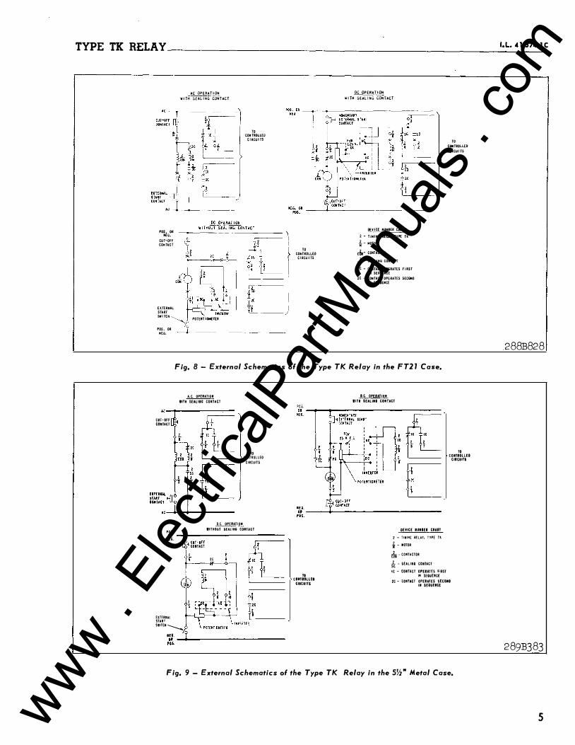
Fig. 8 - External Schematics of the Type TK Relay in the FT21 Case.
A.C. OPEIIATIOII IITM SEAUII; COKTACT
AC-�--------
CUT·OfF COli TACT
AC-+--�------
TO tOMTROLLEO
CIRCUITS
POS. D.C. OPEIIATIOII
IITHOUT SUUM; COIIUCT
"-":!:::::;;--------;::==== "'· CUT·OFr COIUCT
' •
' ffi
HTERUl START SIITCM ---....
1C
"L � t ' '
11:11. ��--+---------------
TO COIITIOLUD
"ICUITI
D.C. OPUATIUII
IITI $EALIU COIITACT
"L" 1 1 i f
DEVICE IUUU CMAIT
2- riMIMG RHH, TYPE U t- MOTOR
� -COIITACTOR
it- SEALIIIQ COITACT
1C-COIIT.lCT OPUAHS fiRST IPI SEQUEIICE
TO COIITIOLLfD
CIIC.UITI
2C - tOIITACT OPERATES S[COIID Ill SEQUUCE
Fig. 9 - External Schematics of the Type TK Relay in the SW' Metal Case.
288B828
289B383
5 www . El
ectric
alPar
tMan
uals
. com
TYPE TK RELAY __________________________ ____________________ ___
and 20 amperes for l minute . The break con
tact has somewhat less pres sure and will
carry about 2/3 this rating. The contacts
wil l op en 2 amp eres at 1 25 volt s d-e; or a
non-inductive current of 20 amperes at 115
volt s a-c or 15 amp eres at 230 volts a-c .
A make sealing contact is supplied on some
relays . When supplied it is connected as
shown in figures l ,3, 4 and 6 and will keep the
relay energized until the circuit is op ened by
a switch or cont act external to the relay .
INSTALLATION
Inspect relay for any damage that might have
occured in shipment . When removing the
blocking from the contactor armature , make
sure that the armature has not shifted off it s
bearings . The armature blocking strips may be
left in the relay , with the short slotted ends
turned upward, for use in ca se of pos sible
future shipment of the relay . Rota te the
tripping disc mechanism counter-clockwise and
allow to reset to make sure tha t it returns to
zero positively. Remove the cover strip at
the top of the gear case . This can be readily
done by pulling aside one end of the strip
which ccvers the sides and bottom . This strip
is held against the top corner posts by a
spring . When the bent -over end is clear of
the top strip , the strip can b e lifted off ,
exposing the sliding gear a s semply and the gear
gear
position index plate .
on clutch shaft set
With, the large
opposite the 30-
second mark on index plate, rotate this gear
s lowly in order to check for app arent friction
in gear train .
The relays should be mounted on switchboard
p anels or their equivalent in a locat ion free
from dirt, moisture, excess ive vibration , and
heat . Mount the relay vertically by means of
the four mount ing hol es on the flange for
semi-flush mounting or by means of the rear
mounting stud or studs for pro jectdon mountin&
Either a mounting stud or the mounting screws
may be utilized for grounding the relay . The
electrical connections may be made directly to
the t erminals by means of screws for s teel
panel mounting or to the terminal studs fur
nished with the relay for thick panel mounting.
The terminal studs may be easily remove d or
insert ed by locking two nuts on the stud and
6
then turning the proper nut with a wrench.
For detailed FI' case information refer to
I . L. 41 -076.
SETTINGS The type TK Relay is set for the desired
operating time by two adju stment s:
l . Remove the cover strip at the top of the
gear train assembly and shift the gears to the
desired time scale .
In order to minimize the mechanical shock
due to the quick reset , the time scale used
should be the longest of the three which will
permit the relay to b e desired operating time .
following paragraph ) .
set for the
( S ee the
shortest
third
2. Then loosen the thumb nut locking the
two trip discs to the trip mechanism shaft ,
and rotate them until each index pin is op-
posite the desired scale marking .
tighten the thumb nut .
Securely
The disc nearest the scal e p l ate will trip
the left finger only; the disc that is neare st
the front wil l trip both contact fingers . To
set the contact fingers for sequential opera
tion the left finger must trip first , as the
motor is in series with the b ack contact s on
the right -hand side . When this finger is
tripped, it op ens the motor circuit .
In making these settings
should not be rotated so that
the trip disc
the trip pins
are holding the Micarta aPms p art way up .
Under this condition it is possible for the
moving contacts to bounce under these arms and
close the front contacts instantaneously when
the relay is energized. The minimum s ettings
obtainable without p artially raising the l atch
arm are approximately l-l/2 division on the 30 second scale , .and corre sponding points on the
other scales.
In some applications it may be desired to
have the l eft-hand contact operate instantan
eously, as soon as the relay is energized, and
have time delay on the right-hand contact
only . This can be done by setting the disc
nearest the scale p l ate so that the l eft-pand
l atch arm is raised above the end of the con
tact finger when the trip disc� are reset . If
www . El
ectric
alPar
tMan
uals
. com
't
TYPE TK RELAY _________________________________________________ I_.L_. 4_t_-s_�_. t_c
any time -delay i s desired, however , the mini
mum setting obtainable without the pos sibility
of erratic operation i s the point at which the
trip di sc begins to rai se the l atch arm .
ADJUSTMENTS AND MAINTENANCE
The proper adjustment s to insure correct
operation of this rel ay have been made at the
fact ory
ceipt by
and should not be dis turbed after re-
the customer . If the adjustment s
have been changed, the relay taken apart for
repairs , or i f it i s de sired to check the ad
justment s at regular maintenance periods , in
struct ions below shoul d be fol l owe d .
Synchronous Motor
The motor bearing contains a supp ly of
lubricant sufficient for 3 t o 5 years of ser
vice under average conditions . Since in gen
eral application of the relays , some may be
required to operate at an ambient temperature
of -30° or -40° F, and others may be required
to operate at an ambient temp erature of over
1 00° F, a sp ecial oil is used whi ch retains
sufficient fluidity at l ow temperatures and
does not oxidize or deteriorate otherwise at
high temperatures . For relubrication of the
motor a fter a period of servi c e , thi s oil i s
supplied in l ounce bottles a s 3#1723639 . B e
cause of the c l o s e tolerances h e l d i n manu
facture , no attempt should be ma de to repair
the motor in case of damage . I t should b e re
turned to the factory for repair or a comp l ete
new motor ordered a s a replacement .
Gear Train & C lutch
The gear train shafts run at l ow speeds and
require no lubrication . The mesh of the gear
teeth on the sliding gear assembly of tne
c lutch shaft shoul d be inspected and the hub
shifted slightly i f necessary to secure a ful l
mesh . Then tighten the set screw securely .
When the armature i s hel d closed , the c lutch
teeth should have a ful l mesh and there should
be l/32 " t o 3/64 " foll ow on the clutch spring .
Any nec essary adjustment should be made by
means of the lower screw in the bracket of the
front of the armature , and the lock nut
should be securely tightened . One-quarter
turn of the adjusting screw, after the clutch
is closed and with the operating spring just
t ouching the c lutch pinion without deflection,
wil l give about l/32" foll ow on the spring .
When the armature is released, the clut ch
teeth should have sufficient s eparation to
prevent any interference with resetting of the
trip discs . T oo much fol l ow on the clutch
spring wil l prevent the clutch from being held
open positively when the relay is de -ener
gized . A small drop of the same oil that is
recommended for relubrication of the motor
shoul d be applied t o the clutch pinion bearing
at intervals of six months to one yea r . It
can be applied by dipping a sma l l wire into
the oil and t ouching this t o the clutch sha ft
between the two clutch discs . A very sma l l
amount o f oil i s suffi ci ent . A drop of oil
may be applied to the teeth of the clutch
pinion at the same t ime .
The shaft assembly on which the tripping
di scs are mounted i s assembled s o that its re
set spring has approximately l -l/4 turns ini-
* tial tension with shaft fully reset . There
should be 20 grams or more pressure required
at the front trip disc screw to just move the
shaft assembly to the left .
Trip Mechani sm
The die -case bracket which support s the l atch arm as sembly is secured to the front gear p late by means of screws pas sing through
slotted holes . To adjust the position of this
bracket, l oosen both the mounting screws and
the screw which holds the stop bracket for the
right hand ( front view ) l atch arm . Move the
sliding gear assembly out of mesh, so that the
trip di scs wil l not rotate , and energize the
relay . The l atch arms should be down so that
the contact fingers are held out . Shift the
die -case bracket so that with the l atch arms
touching the aluminum trip disc s { not the trip
screws ) , the pro jection of the end of the
l atch arm above the top o f its adjacent con-
* tact finger wil l be . 090 inch for the l eft
* hand finger and · 095 inch for the right -hand
finger . The dimensions given apply to rel ays
in which the trip discs are l -1/8 inch in
diameter . Earl ier rel ays used discs with a
diameter of 1 - 3/16 inch and on these the dim-
7 www . El
ectric
alPar
tMan
uals
. com
TYPE TK RELAY ______________________________________________ ___
ensions shoul d be . 01 0 inch for the left -hand
finger and . 120 inch for the right -hand
finger . A small strip of metal with the ends
filed to these dimensions wil l be convenient
to use as a gauge . It can be rested on the
ends of the contact fingers and the bracket
shifted until the upper front corners of the
fingers are even Mith the ends of the gauge .
Tbe mounting screws for the bracket should
then be tightened securely . The screw for the
right -hand latch arm stop bracket shoul d be
tightened and the bracket should be bent up or
down until the latch arms just clear the small
bronze index pins projecting from the trip
disc .
Rai se the right -hand latch with the fingers
and move the armature in by hand until the
tips of the contact fingers are opposite the
l owest p ortions of the latch arms . When the
left -hand latch arm is just touching its con
tact finger , there shoul d be a gap of about
. 01 0" to . 01 5 inch b etween the right -hand arm
and its contact finger . (This relation be
tween the latches and the contact fingers pre
vents any possibil ity of the left -hand finger
tripping first when the trip discs are set for
simultaneous tripping ) .
Loosen the thumb nut locking the two trip
di scs and energize the relay with the gears
still out of mesh . Hold the final gear firmly
against its back stop , and rotate each trip
disc by hand until it depresses its latch arm far enough to just trip the c ontact finger .
The bronze p in pro jecting from each trip disc
serves as its zero index , and should be op
posite the zero on the dial when the contact
finger trip s . The trip screws are prevented
from turning by a locking wire spring which
passes through a slot in the inner end of the
trip screw and is accessible from the rear of
the trip di sc . It should b e moved out of the
slot , and the trip screw shou l d be screwed in
or out until the index p in is opposite the
zero on the dial when the contact finger is
releqsed . Then the locking spring should be
placed in the slot o f its trip screw to pre
vent any acc idental change in adjustment . The
trip discs should rel ease the contact fingers
When the trip screws are one scale division or
8
more from the center or lowest position .
Repeated tests have shown that the rel ay
wi ll make more than one million operations b e
fore the striking and rubbing action of the
contact fingers on the ends of the latch arms
wears them sufficiently to require replace
ment .
Contactor
All contacts should be cleaned p eriodically .
A contact burnisher S#l82A836HOl is rec ommended
for this purp ose . The use of abras ive material
for cl eaning contacts is not recommended be
cause of the danger of embedding sma ll part i
c l es in the face of the s oft silver and thus
impairing the contact .
The stationary contacts shoul d be adjusted
by b ending so that both moving contacts make
simultaneously when they move in with the
armature , with about l/16 inch follow . With
the relay de -energized, adjust .the p osition of
the left -hand back contact spring , by means of
the adjusting screw so that there will be a
* gap between the latch arms and the contact
fingers sufficient for the latch arms to clear
the contact fingers when resetting . T ighten
the lock nut se curely . The gaps between the
contact fingers and the ends of the latch arms
should be approximately equal . If the gaps
are unequal , the contact fingers probably have
been bent . When the relay i.s de-energized and
the front clutch member is at the limit of its
outward travel there should be a slight clear
ance between the clut ch spring and the washer
at the front of the clutch pinion . There
should also be clearan ce between the clut ch
spring and the dial plate .
The motor c ircuit contact should have l/16
inch to 3/32 inch follow when the right-hand
contac t finger is against the latch arm . When
the motor circuit is open , there should be no
gap between the rear contact spring ( in w!1i ch
the flat contact is assembled ) and its stop
p l at e .
www . El
ectric
alPar
tMan
uals
. com
TYPE TK RELAY __________________________________________________ 1·_L._4_1�_7_� __ 1 c
On rel ays provi ded with a seal ing c ontac t ,
adjust the upper screw i n the bracket a t the RENEWAL PARTS
front of the armature so that there wil l be Repair work c an be done most sati sfactori ly
1/32 inch to 3/64 inch follow in the seal-in
c ontact after it has c losed . Tighten the lock
nut securely . When the relay is de -energized
the seal -in contact shoul d have 1/32 inch to
3/64 inch gap .
at the factory . However , interchangeab l e
p art s c a� be furnished t o the customers who
are equipped for doing repair work . When
ordering parts , always give the c omplete name
p late data .
ENERGY REQUIREMENTS
The burden of the Typ e TK Relay at 1 1 5 vol t s , 60 cycles i s as foll ows:
Circuit
Motor
Contactor
Cont inuous Volt Rating
1 15
1 1 5
Watts Reactive
1 . 8 1 . 73
1 1 . 5 14 . 5
V . A . Vol t -Amp s . P . F .
2 . 5 4 0 Lag
1 8 . 5 51 ° Lag
The burdens at the other 60 cyc l e voltage ratings wi ll be approximately the same as above .
� DRI LL (2 HOLtS)
N O . O F DRI L L HOL ES TER M I NALS
8 OR LESS I TO 8 ..9 I TO 9 1 0 I TO 1 0
M DRI L L (AS REQU IRED)
rr l I I I
�m--------------------nn
NOT C FOR '/�"oR 3/11C"' M E rAL sw'£3 DS USE SCREWS FOR M TG. RELAY AN D fOR TERM I NAL CON N S . FOt-( '/4" TO I '" SW£:)Ds USE_ ST U D S FOR MTG. RELAY A N D SCRE:.II\/5 FOR lt: F< M I NAL CON N S . FOR . A L L OT H E R: SWBDS US E:: S r U D S FOR BOTH PURPO�ES.
f-20 T H 'D.
56-D-815
Fig. 10 - Outline ancl Drilling Plan for the S!IZ• Metal Case With a Glass Front, See the International Diagrams for the Ter• minals Supplied, For Reference Only.
9 www . El
ectric
alPar
tMan
uals
. com
TYPE TK RELAY ____________________________________________ __
10
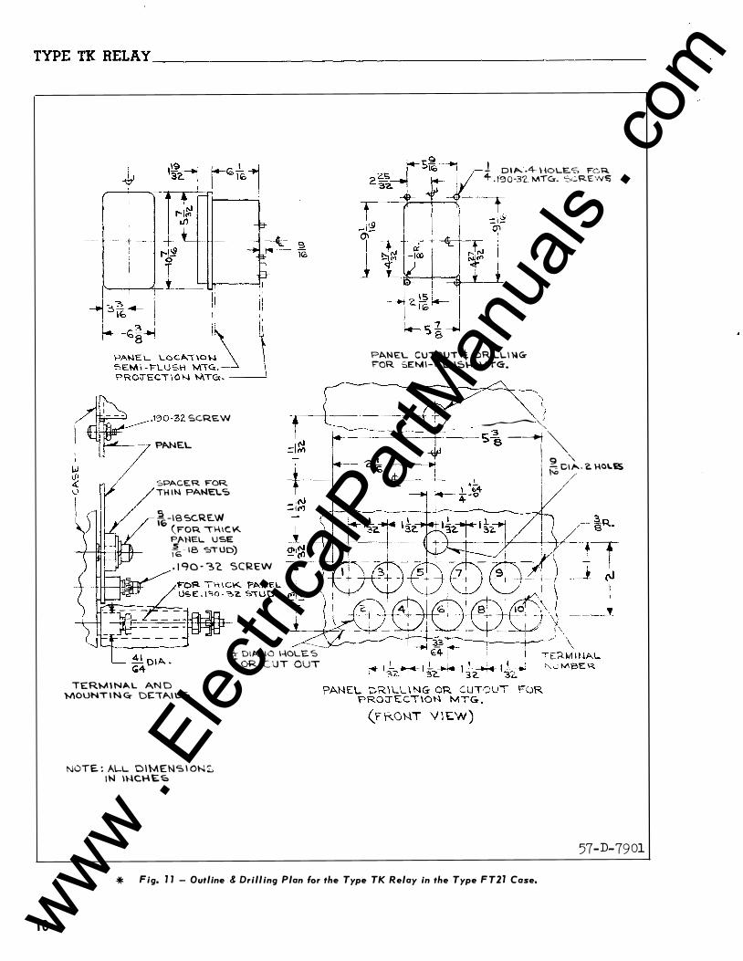
� ____..-- · 1 '3 0 -32. SC.RE.W I �--·- P�NE.L , L
SPACER FOR TI-l l� P�NEL.S
� -16 SCRE..W IG (FOR \1-\IC ¥<.. PANEL. USE �- 18 '=:>TUD) - 1 '70 - �'2. SCREW
TERM I N�L AN D 'MOUNT I N c;.- DE: I A.l L S
NOTE : ALL OIMENS I ON S I N 1\-lC\-\E�
-..::;: ---� 4 D\�. 10 1-\0U�. S OR C U T OUT
l DI�-.4- \-IOLE.S FOR 4- . 190·3'2. MTC:r. S<.:.REW!:;
PANEL CUTOUT t DRIL.L\ '-lG;:-oR SEM\-F LUS\-1 lvtTG-.
") ' i
�-,: 1-.-------+--� - s� ---t'�
I g " I \....., C\..._ , 'a. H0�12S l "' /' I
57-D-7901
* Fig. l J - Outline & Drilling Plan for the Type TK Relay in the Type FT2l Case,
www . El
ectric
alPar
tMan
uals
. com

www . El
ectric
alPar
tMan
uals
. com
W E S T I NG H O U S E ELECTRIC CORPORAT ION R E LAY D E PA RTM E N T N EWA R K, N. J.
Printed in U. S. A. www . El
ectric
alPar
tMan
uals
. com

I. l. 41 -57 4
INSTALLATION • OPERATION • MAINTENANCE
INSTRUCTIONS TYPE TK TIMING RELAY
CAUTION Before putting relays into service ,
remove all blocking which may have been in
serted for the purpose of securing the parts
during shipment , make sure that all moving
p art s operate freely, inspect the contacts to
see that they are clean and close properly,
and operat e the relay to check the settings
and electrical connections .
AP PLICATION
The Type TK Relay is an a-c timing relay for
applicat ions requiring a definite time delay
between the closing of an a-c circuit and the
closing or opening of other d-e or a-c cir
cuit s . Accurate t ime -settings from two sec
onds to fifty minutes can be obtained, and ,
for any setting , the reset t ime is les s than
one second .
The relay i s used where t ime delay is re
quired in motor , generator , rect ifier , voltage
regulator or tap changing transformer control
circuits . It is also widely used in indus
trial applications .
One style of the relay i s available for use
with a d-e or a-c inverter where a reliable
a-c control voltage is not available . The in
verter is covered in I . L . 41 -54 5 .
CONSTRUCTION AND OPERATION
The typ e TK relay consi sts of a synchronous
motor, a gear train to provide three different
ratios , a clutch interposed in the gear train
to permit quick resetting when the relay is
de-energized, a contactor which carries the
main contacts and operates the clutch , and a
tripping mechanism adjust able for t ime -delay .
SUPERSEDES I. l. 41-366M * I:·anotes change from superseded issue.
Synchronous Motor
The motor for driving the gear tra in i s
located on the back plate o f the gear train
assembly in the lower right -hand corner . It
runs at a synchronous sp eed of 600 , 500 or 250
R . P . M . for 60, 50 or 25 cycle relays re
spectively . Its bearing has an oil reservoir'
with sufficient capacity for sevePal years of
normal operation . On relays Pat ed at 230 or
higher , the contactor coil has a tap brought
out at the proper place to act as an auto
transformer to supply 115 volt s fop the motor .
Gear Train and Clutch
The gear train is as sembled as a separate
unit and consists of two brass bearing plates
fastened together at the corners by brass
posts . The gear shaft s run at low speeds and
require no lubricat ion . The three different
speeds are obtained by changing the location
of a sliding gear as sembly . Thi s assembly
consists of two gears on a hub that is free to
slide on the clutch shaft and can be locked in
any de sired position with a set screw . The
hub is moved to the posit ion where the larger
gear is opposite the arrow on the index plate
corresponding to the desired t ime scale .
The clutch is two aluminum disc with ser
rated faces , arranged so that they are posi
t ively engaged and disengaged by a spring arm
on the contactor armature when the lat ter is
in its closed and open posit ions respectively .
The rear disc i s fastened to a shaft on the
gear train . The front di sc is a running fit
on the end of the same shaft . The latter disc
has fastened to it the p inion which drives the
tripping mechanism . When the relay is ener
gized, the clutch discs engage and power is
transmitted from the motor, through the gear
EFFECTIVE APRIL 1955 www . El
ectric
alPar
tMan
uals
. com
TYPE TK RELAY-----------------------
t rain , t o the t ripp ing mechanism . When the
relay is de -energized, the c lutch di s c s are
separate d by the opening of the contac tor arm
ature .
Cont ac t or
The c ont actor i s a c l apper typ e el ement
with a E shap e d magne tic frame with a sol e
noid c o i l on the c enter l eg . The moving arma
ture i s hinged at the b ot t om of the magnetic
frame , and held open by a spring below the
hinge . A spring arm is fastened to the t op
c ent er of the armature , and i t s outer end
presses against the front hal f of the clutch
when the contac t or coil i s energize d . The
p o si t i on of thi s arm is c ontrol led by an ad
justing screw on a bracket fastened to the
front of the armature .
Two c ontac t fingers are p ivoted at the l ower
end of the armature and each i s free to move
independently of the armature against a spiral
spring . Silver cont act s are fast ened near the
t op ends of the fingers . The stati onary c on
t ac t arms have s il ver c ontact surfac e s o n the
out er ends , and are fastened to terminal p o s t s
in t h e bas e . The make s t ati onary cont ac t s are
mounted on l eaf spring s with rigid back -up
arms t o l imi t the defl e c tion . Thi s c onstruc
t ion in which both moving and stat ionary c on
tact arms deflect s lightl y , when c ontact is
made , minimizes the p o s sibility of the con
t ac t s opening momentari ly under severe shock .
The break stat i onary contact arms are l eaf
spring s with rigid supporting arms to prevent
overtravel .
The 1notion of the armature c auses the clut ch
di s c s to engage but wi l l not c l o se the con
t ac t s until the trip mechani sm l at ches are re
leased . When these latches are rel eased and
if the armature is s t i l l c l o s e d the contact
arms move to the op erat ed p o s it ion by the
action of the spring s c onne c ting the c ontact
arms t o the armature .
Some styl e s of the Type TK Rel ay are pro
vide d with a seal ing c ontact t o seal -in the
c ontactor c oil until the circui t is opene d by
an ext ernal c�ntact or switch ( such as a push
but t on ) . The seal ing c ontact is operat ed by
2
an adjust ab l e Mic arta but ton extending from
the same armature b racket which c arri e s the
adjus t ing screw for the clutch operat ing arm .
Thi s but t on c l oses a make c ontact mounted on
t op of the magne tic yoke of the c ont ac tor .
Trip Mechani sm
The trip mechanism i s carried on a shaft
thru the t op of the gear t rain as semb l y . A
large gear, a c ircular s c al e and t wo adjust
ab l e trip di s c s are attached t o this shaft .
The large gear me shes with the pini on on the
front cl ut ch di s c . The trip di s c s each have a
smal l b ronze index p i n proje c t ing approx i
mat ely l/3 2 " from i t s e dge . A hexagon headed
trip s c rew in each di sc operat e s one of the
two latch arms which in turn releases the
moving contact arms t o operate the c ontac t s .
The latch 2 rms are mount ed between b racket
arms ext ending from the gear train front
p l ate . The arrangement is such that the inner
t rip disc operate s onl y the l eft hand latch,
whi l e the out er trip di s c operat e s. both l atch
arms . The moving c ontact arms c an 0perate
only i f the armatur•e is c l osed . The trip me
chani sm shaft re sets by the act ion of a spring
fastened to the shaft and the gear t rain a s
s emb ly p l at e . The mechani sm i s adjusted s o
that the index p ins are opposite t h e zero on
the scale �ate when the trip s c rews in the
d i s c s have reache d a point where they just
rai s e the Mi c arta latch arm suffic ient ly t o
release the c ontact arms , the trip di s c s being
rotated manual ly for thi s check whi l e hol ding
the shaft agai nst i t s stop .
CHARACTERISTICS
In the 50 and 60 cyc l e relays the maximum
t ime sett ings availab l e for the three gear
p os i t ions are 30 seconds , 5 minut es , and 50
minut e s , The smal lest sub -divis ion is l s e c
ond o n t h e 30 second s cale, 0 . 1 minute o n the
5 minute scal e , and l minut e on the 50 minute
s c al e .
In the 25 cyc l e rel ays the maximum t ime
s e t t ing avai lab l e for the three gear posit ions
are l , 1 0, and 1 00 minut es . The small es t sub
divi sion i s 2 s e c onds on the l minute s c al e ,
0 .2 minute on the 10 minute s c al e , 2 minutes
on the 1 00 minute s c al e .
www . El
ectric
alPar
tMan
uals
. com

TYPE TK BELAY
INTERNAL SCHEMATIC
CONTACTOR COIL
REAR V IEW
I-OPERATES Fl RST IN SEQUENCE t·OPERATES NEXT I N SEQUENCE
FOR 250 V AND UP CONNECT TO TA P ON CONTA CTOR COIL
MOTOR
Fig. 1-lnternal Wiring Diagram of the Type TK Relay with Sealing Contacts (for a-c Operation) in the SV2" Metal Case.
RELAY TYPE TK TIMI NG, I MAKE + I MAK E - BREAK,
��JY�c��gNs����r CONTACTS, FOR AC QPERATION, IN STANDARD
INTER NAL S C H E M ATIC
MOTOR
REAR V I EW
I-OPERATES FIRST IN IIEQUENCE 2-0PERATES NEXT IN S[QU!NCE
SEALING CONTACT
��� ��0 v CONNECT TO TAP ON CONTACTOR COIL
78-D-201
Fig. 3-Internal Wiring Diagram of the Type TK Relay With Sealing Contacts (for a-c Operation) in the Standard Case.
I. l. 41 -574
MOTOR CONTACT
INTERNAL SCHEMATIC
REJIR VIEW
I-OPERATES FIRST IN SEQUENCE z-OPERATES NEXT I N SEQUENCE
FOR Z30 V AND UP CONNECT TO TJIP ON CONTACT OR COIL
MOTOR
56-D-806
Fig. 2-Internal Wiring Diagram of the Type TK Relay Without Sealing Contacts (for a-c. Operation) in the 5 V2" Metal Case.
RELAY TYPE TK TIMING, I MAKE + I MAKE- BREAK, MOTOR CONTACTS WITHOUT SEALING CONTACT, FOR AC OPERATION, IN STANDARD PROJECTION CASE.
liD TOR CONTACT
IN TERNAL SCHEMATI C
r--- -�2 - - � I® :' Q) ,. i ® 1 ;: @
1 10��·) I
I L _ _ _ _ __/ REJIR V IEW
r OPERJITEI .FIRIT IN &EQUENCE t" OPERATES NEXT IN SEQUENCE
FOil 230 V a"Jl,lllcT TO TAP ON CONTJICTOR COIL
78-D-202
* .Fig. 4-Internal Wiring Diagram of the Type TK Relay Without Sealing Contacts (for a-c Operation) in the Standard Case.
3 www . El
ectric
alPar
tMan
uals
. com
TYPE TK RELAY ____________________________________________ __
*
The re set time for maximum travel i s less
than one secon d . Since the clutch i s disengages to reset, the reset time i s independent
of the po sition of the sli ding gear assembly .
The motor may require one or two seconds to
reach synchronous speed after the relay is en
ergized and its . average speed during thi s ac
celerating period will b e something les s than
synchronous speed . The time scale s on the
dial make no provi sion for the effect the ac
celerating period has upon the total operating
time, as thi s i s not noticeable on the inter
medi ate or slow speed settings . When the
gears are in the high speed position , i t will
b e more accurate to u se a scale setting ap
proximately one second le ss than the des ired
time setting . The motor will operate at 10% above or 1 5% under rated voltage .
The two sets of main contacts can b e ad
justed to operate either s imultaneously or s e
�uentially . The left hand s e t is single pole
double throw (make & break ) and the right hand
set is s ingle pole single throw (make ) . The
right hand contact arm also operates the inde
pendent break motor circuit contact . The make
contacts will carry 12 amperes continuously
and 20 amperes for l minute . The break c o n
tact has somewhat les s pres sure and will
c arry about 2/3 thi s rating . The contacts
will open 2 ampere s at 125 volts d - e ; or a
non - i n du c t i v e c u rrent of 20 ampe re s at 1 1 5 volts a - c -�r 1 5 arr:peres at 2 3 0 vol t s a - c .
A Bake se a l i ng c ontac t i s supplied on some
r e l a y s . When supplied it is connected as
shoKn i n figures l, 3 and 6 to 9 and will keep
t h e relay energized un t i l the circuit is
c p e n e d by a switch or contact external to the
INSTALLATION
b l c 2k i�g fr�m the S J�t 2 2 t 0r a r�g :�re , �ake
sure �haL the a rmat�re h a s n e t sh i f t e d � f f its
b t a r t : .gs . The a rma ture b l o �king strips may b e
l e f t i n the re l a y , with the sh. rt slo tted e n d s
f: r � s o ' • c � s � o f pos sible
4
tripping disc mechani sm counter-clockwi se and
allow to reset to make sure that it returns to
zero positively . Remove the cover strip at
the top of the gear cas e . Thi s can be readily
done by pulling aside one end of the strip
which covers the side s and bottom . This strip
is he l d a g a in st the top corner posts by a
spring . When the b ent-over end i s clear of
the top strip, the strip can b e lifted o f f ,
exposing the s l i ding gear a s semb l y and the
gear position index plate . With the large
gear on clutch shaft set opposite the ]0-s e c on d mark on index plate, rotate thi s gear
slowly in order to check for ap p a re n t frictlon
in gear train .
The relays should b e mounted on switchb oard
panels or their equivalent in a locati on free
from dirt, moisture , exce ssive vibration and
heat . Mount the relay vert i c a l l y by means of the two mounting studs for the standard cas e s
and the type FT proj ection case or b y means of
the four mounting holes on t h e flange for the
semi -flush type FT case . E ither of the studs
or the mounting screws may be utili zed for
grounding the relay . The e l ectrical con
nections may b e made direct to the terminals
by means of screws for steel panel mount ing or
to terminal studs furni sh e d with the relay f o r
ebony-asbe stos or slate p an e l m o �1 � l ng . The
terminal studs may b e e a si l y remo v e d or in
serted by locking two nu t s u n the s t u d s and
then turning the proper nut with a wren ch .
Any appreciable variatiun frcm a level pcsi
ti on will affect the op e r a t i ng c h a ra c t er i st i c s
of t h e relay .
The internal and s che�3tic external wiring
diagrams are shown in figures l t�r� l l . The
operation of the d-e to a-c i nverter
c overed in a separate instructiun l eaflet .
SETTINGS
i s
The type T K Relay i s set for th e desired
operating time by two adjustments:
l . Remove the c o ver strip at the top of the
gear train assembly and shift the gear s tc the
desired time scale .
In order tD ffii�imi z e the ffiechani cal sho �l� cue t : t
www . El
ectric
alPar
tMan
uals
. com
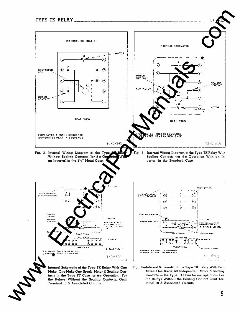
TYPE TK RELAY _________________________________________________ �t�L�4�1 - 5�74
CONTACT R COIL
MOTOR CONTACT
INTERNAL SCHEMATI C
M
@�----�\�-----
REAR V IEW
I-OPERATES FIRST I N SEQUENCE
z-OPERATES NEXT IN SEQUENCE
OTOR
78 -D-245
Fig. 5-Internal Wiring Diagram of the Type TK Relay Without Sealinq Contacts (for d-e Operation With an Inverter) in the SVz" Metal Case.
/ . CO\IE'R OPE'ri::A"'i EO S..,.mc.\-1. VII\\£� US'C.U.
SEALING C.oNIPo.C.."T MO\OR
U> N TP.C.T
C.ONTAC.TOR. --
\ ()f'E.RA"TE_S f\R:S.\ IN S E. Q U EN.C..E 2. 0P £.RATES No E.XT \N. SE-Q\lEMC.E.
'( -D-6699 L-----------------------------------------------�
Fig. 7-Internal Schematic of the Type TK Relay With One Make. One-Make-One Break. Motor & Sealing Contacts in the Type FT Case for a-c Operation. For the Relays Without the Sealing Contacts, Omit Terminal 10 & Associated Circuits.
MOTOR CONTACT
INTERNAL SCHEMATIC
RE A R V IE W
I -OPERATES FIRST I N SEQU E N C E 2-0P ERATES N E XT I N S E QU E N C E
-rs -D - 2 1 4 I L----------------------------------------------------'
Fig. 6-Internal Wiring Diaqram of the Type TK Relay With Sealing Contacts (for d-e Operation With an Inverter) in the Standard Case.
FRONT VIEW
1-0PERA.TE5 FIRST IN $£QUENC.E.
e-oPERATES NE)(T IN �E.C\UE.NC£.
�--------·--------------------------
.o t!.A.SE. Tk.RM.
7-D-6703 ·---- ---...!
Fig. 8-Internal Schematic of the Type TK Relay With Two Make, One Break All Independent Motor & Sealing Contacts in the Type FT Case for a-c operation. For the Relays Without the Sealing Contact Omit Terminal 10 & Associated C:ircuils.
5 www . El
ectric
alPar
tMan
uals
. com
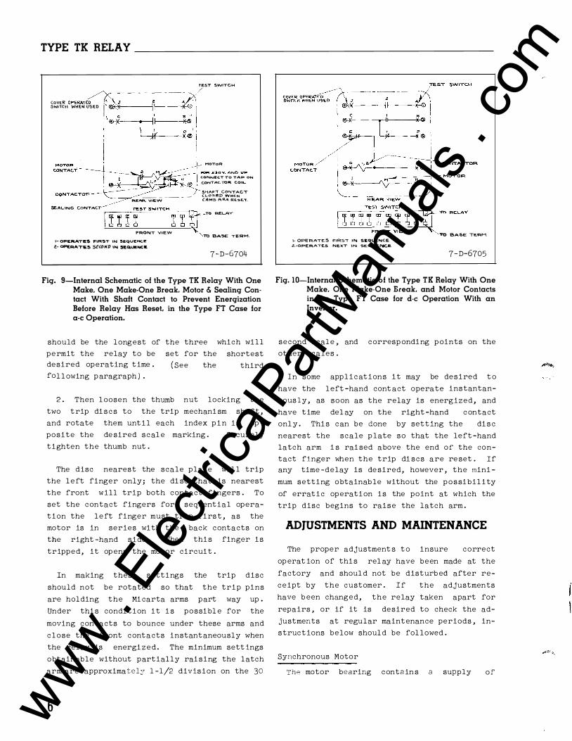
TYPE TK RELAY
TEST SWITCH
COVER OPERAlE� -J
-- - -�·� - --� :>(' /
SWllCI-l WHE� USED I ®: :x . . k" :1 I ., ®�X --.----ld ;: i I '
CONTACTOR �---� __ _ __ _ --
A.EAP... VIEW
SEALING CONTACT ,----'T-=Ec::ST-'--=5--'WCCIT'-'C'--H'------n-,
FRONT V)EW 1- 0PE.RAT�S FIRST IW SI!QUEHC.e: 2- oPERAT1i.:. SCCOND '"" SEQUENC.W.
MOTOR
c;ONNEC.T To TAP ON C.ONTAC. TOR, COIL
S!-iAF=T CONTACT (LOS.f!D WHEN CAMS R'R.E. RE�E.."f.
TO RELAY
TO BA5E TERM.
7 -D-6704
Fig. 9-Internal Schematic of the Type TK Relay With One Make. One Make-One Break. Motor & Sealing Contact With Shaft Contact to Prevent Energization Before Relay Has Reset, in the Type FT Case for a-c Operation.
should be the longest of the three
permit the relay to be desired operating time .
fol l owing p aragraph ) .
set for the
( See the
which will
shortest
third
2 . Then l oosen the thumb nut locking the
two trip di s c s to the trip mechani sm shaf t ,
and rotate them until each index p i n is op
posite the de sired scal e marking . Securely
tighten the thumb nut .
The disc nearest the scale plate wil l trip
the left finger only; the di sc that is nearest
the front will trip both contact fingers . To
set the contact fingers for sequential opera
tion the left finger must trip firs t , as the
motor is in series with the back contacts on
the right -hand side . When thi s finger is
tripped, it op ens the motor circuit .
In making these settings the trip disc
should not be rotated so that the trip pins
are holding the Mi carta arms part way up .
Under thi s condition it i s possibl e for the
moving contacts to bounce under these arms and
c l ose the front contacts instantaneously when
the relay is energi zed . The minimum sett ings
obtainable without partially rai sing the latch
arm are approximatel;;r 1-1/2 division on the 30
6
I· OPERATE.S f:JR5T IN SEQUENCE
Z.-OPERATES NE.XT IN SEQUE�E. TO BASE TE�M.
7-D-6705
Fig. 10-lnternal Schematic of the Type TK Relay With One Make. One Make-One Break, and Motor Contacts in the Type FT Case for d-e Operation With an Inverter.
second scale , and corresp onding p oints on the
other scales .
In some applications it may be desired t o
have the left -hand cont act operate instantan
eous ly, as soon as the relay is energized, and
have time del ay on the right -hand c ontact
onl y . Thi s can be done by setting the di s c
nearest the scale p late so that the left -hand
latch arm i s rai sed above the end of the con
tact finger when the trip di scs are re set . If any time -delay is de sired, however , the mini
mum setting obtainable without the possibil ity
of erratic operation is the point at which the
trip disc begins to raise the latch arm .
ADJUSTMENTS AND MAINTENANCE
The proper adjustment s t o insure correct
op erat ion of thi s rel ay have been made at the
factory and shoul d not be disturb ed after re
ceipt by the customer . If the adjustments
have b een changed, the relay taken apart for
repairs , or if it is desired to check the ad
justments at regular maintenance periods , in
structions below shoul d be fol lowed .
Synchronous Motor
The motor bearing conta in s a supply of
www . El
ectric
alPar
tMan
uals
. com
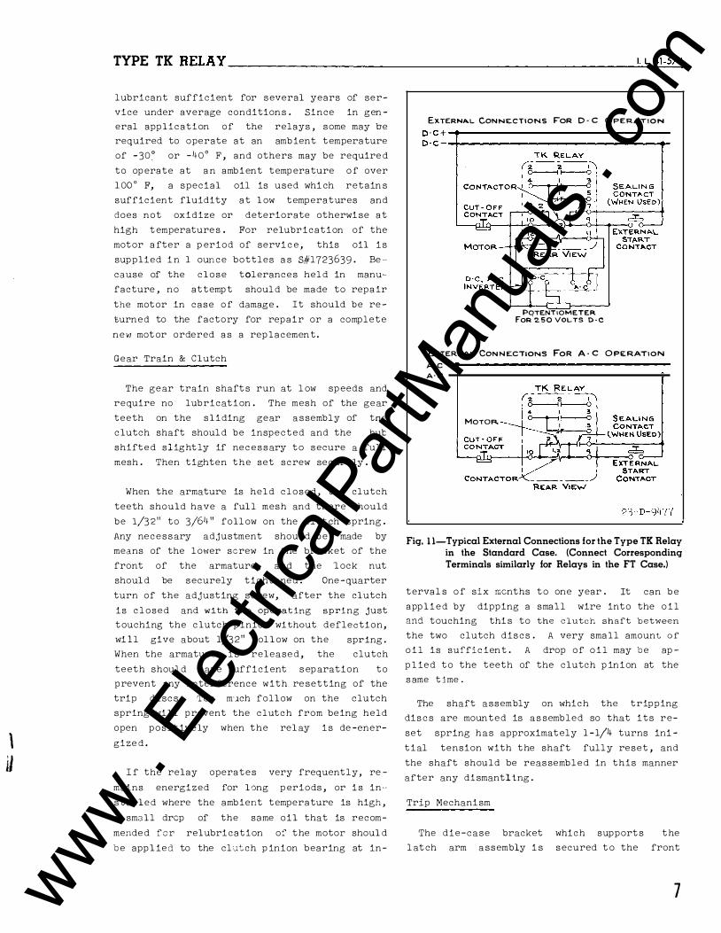
\ il
TYPE TK RELAY----------------------------------------------��-�L�4�1-�57�4
lubricant sufficient for several years of ser
vice under average conditions . Since in gen
eral application of the relays , some may be
required to operate at an amb ient temperature
of - 30� or -40° F , and others may be require d
to op erate at a n ambient temp erature o f over
1 00 ° F, a special oil is used whi ch retain s
sufficient fluidity at l ow temperatures and
does not oxidize or deteriorate otherwi se at
high t emperature s . For relubrication of the
motor a fter a p eriod of servi c e , this oil i s
supplied i n 1 ounce bottles a s S#l723639 - Be ··
cause of the close tolerances hel d in manu
facture , no attemp t shoul d be made to repa ir
the motor in case o f damage . It should be re
turned to the factory for repair or a complete
new mot or ordered a s a rep lacement .
Gear Train & Clutch
The gear train shaft s run at l ow sp eeds and
require no lubrication . The mesh of the gear
teeth on the sliding gear assembly of tne
clutch shaft shoul d be inspected and the hut
shifted slight ly if nec e s s ary to secure a full
mesh . Then tighten the set screw securely .
When the armature is hel d closed , the clutch
teeth should have a full mesh and there should
be 1/3 2 " to 3/64 " foll ow on the clut ch spring .
Any necessary adjustment shoul d b e made by
means of the lower screw in the bracket of the
front of the armature , and the l ock nut
shoul d be securely tightened . One -quarter
turn of the adjusting screw, after the clutch
is c l osed and with the operating spring just
touching the clutch p inion without deflection,
wi ll give about 1/32" fol l ow on the spring .
When the armature i s release d , the clutch
teeth shoul d have sufficient s ep aration to
prevent any interference with re setting of the
trip disc s . Too m·�ch follow on the clutch
spring will prevent the clutch from being held
open positively when the rel ay i s de -ener
gize d .
I f the relay operates very frequently, re
mains energized for long p eriods , or i s in ··
s talled where the ambient temperature is high ,
a small drop of the same oil that is recom
mende d for relubrication of the motor shoul d
b e app l ied to the clutch p inion bearing at in-
EXTERNA.l. CONNECTIONS FoR D · C OPERAT I O N
D·C+ -.-----------------------------------0-C- -+--------------------------------.-
POTENTIOMETER FoR 250 VOt.TS D - C
EXTERNAL CON N ECTIONS FOR A · C OPERATION
A·C
A· C
MOTOR.
Fig. 1 1-Typical External Connections for the Type TK Relay in the Standard Case. (Connect Corresponding Terminals similarly for Relays in the FT Case.)
terval s o f six mcnths to one year . It can b e
app l i e d by dipping a small wire into the o i l
and touching thi s to the clutch shaft between the two clutch dis cs . A very small amount o f o i l is suffic ient . A drop of o i l may b e ap
p l ied to the teeth of the clutch p inion at the
s ame t j me .
The shaft assembly on which the tripping
dis c s are mounted is as sembled so that its re
set spring has approximately 1 -1/4 turns ini
tial tension with the shaft fully reset , and
the shaft should be reas sembled in this manner
after any dismantling .
Trip Mechani sm
The die-case bracket which support s the
l at ch arm assembly i s secured t o the front
7 www . El
ectric
alPar
tMan
uals
. com
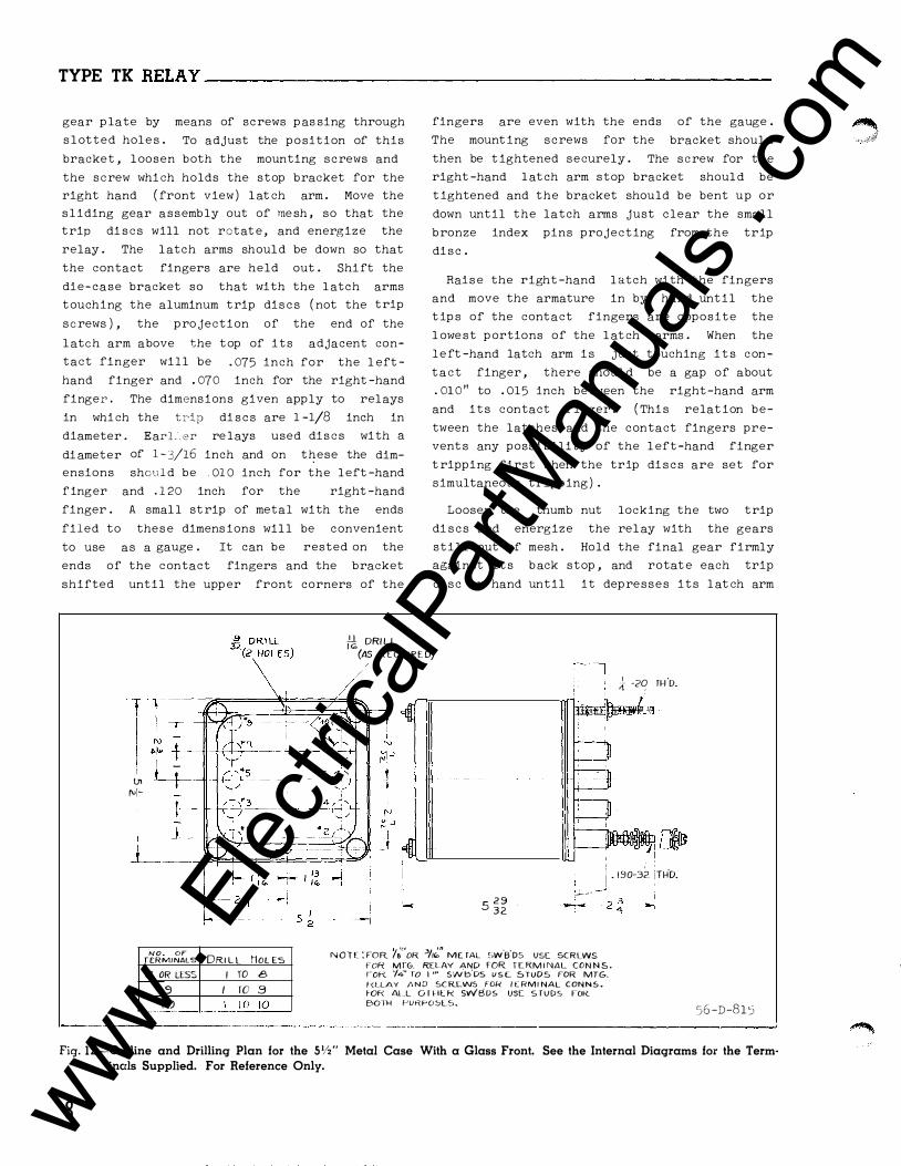
TYPE TK RELAY----------------------------------------------
gear p late by means of screws p as sing through
s l otted hole s . To adjust the position of this
bracket , l oosen both the mounting screws and
the screw whi ch holds the stop bracket for the
right hand ( front view ) l at ch arm . Move the
s l iding gear assembly out of me sh , so that the
trip di s c s will not rotat e , and energize the
relay . The l atch arms shoul d be down so that
the contact fingers are held out . Shi ft the
die-case bracket so that with the l atch arms
touching the aluminum trip dis c s ( not the trip
screws ) , the pro jection of the end of the
l atch arm above the top of its adjacent con
tact finger will be . 075 inch for the l eft
hand finger and . 070 inch for the right -hand
finger . The dimensions given apply to relays
in whi ch the tr-ip di s c s are 1 -1/8 inch in
diameter . Earl er re lays used dis c s with a
di ameter of 1 -3/16 inch and on these the dim
ensions shoul d be . 01 0 inch for the left -hand
finger and . 1 20 inch for the right -hand
finger . A smal l st rip of metal with the ends
filed to thes e dimens ions wil l be convenient
to use as a gauge . It can be rested on the
ends of the contact fingers and the bracket
shifted until the upp er front corners of the
fingers are even with the ends
The mount ing screws for the
of the gauge .
bracket shoul d
then be t ightened securely . The screw for the
right -hand l atch arm stop bracket shoul d be
t ightened and the bracket should be bent up or
down until the latch arms just clear the small
bronze index pins projecting from the trip
di sc .
Rais e the right -hand l atch with the fingers
and move the armature in by hand until the
t ip s of the contact fingers are opposite the
l owe st p ortions of the l at ch arms . When the
l e ft -hand latch arm i s just touching i t s con
tact finger , there shoul d be a gap of about
. 01 0 11 to . 015 inch between the right -hand arm
and its contact finger . ( Thi s relat ion be
tween the latches and the contact fingers pre
vent s any possibility of the l eft -hand finger
t ripping first when the trip di s c s are set for
simultaneous tripping ) .
Loosen the thumb nut locking the two trip
di s c s and energize the rel ay with the gears
still out of mesh . Hold the final gear firmly
against i t s b ack stop , and rotat e each trip
disc by hand until it depresses its l at ch arm
M DRI L L (AS REQU IRED)
[ 1-�---l--� � +-+--' i ! -
lJ1 f'll-
NO. OF fERMINALS 8 OR LESS
.9 / 0 t _ -· ·��------
DRI L L HOL ES I TO 8
I ro .9 _ __ !_TO JQ__
l .t -2� fH D.
I i . 190·3Z !TH'D. I r- 5 2 9
32 ,.J.----- -
-
N O T E : FOR '/�'"oR 3/1�" M£ TAL ,-,w.B'Ds VS£ SCRLWS fOR MrG. RELAY AND FOR T E RM I NA L CON N S . r·on: '/4" ro I '" sv•./t;'Ds U S E. STUDS FOR MTG.
f-(LLAY li N D SC RL.WS FOR f E RM I NAL CONNS • rOF< ALL O I HL f< Svv'BDS VSC S T UDS FOR. BOTH FURf-'OSLS.
56 -D-81 5 ----------------- --- - ------ ----··--------------------------J
Fig. 1 2-0ulline and Drilling Plan for the S1/2" Metal Case With a Glass Front. See the Internal Diagrams for the Term· incrls Supplied. For Reference Only.
8
� '� .jf.:fJ
www . El
ectric
alPar
tMan
uals
. com
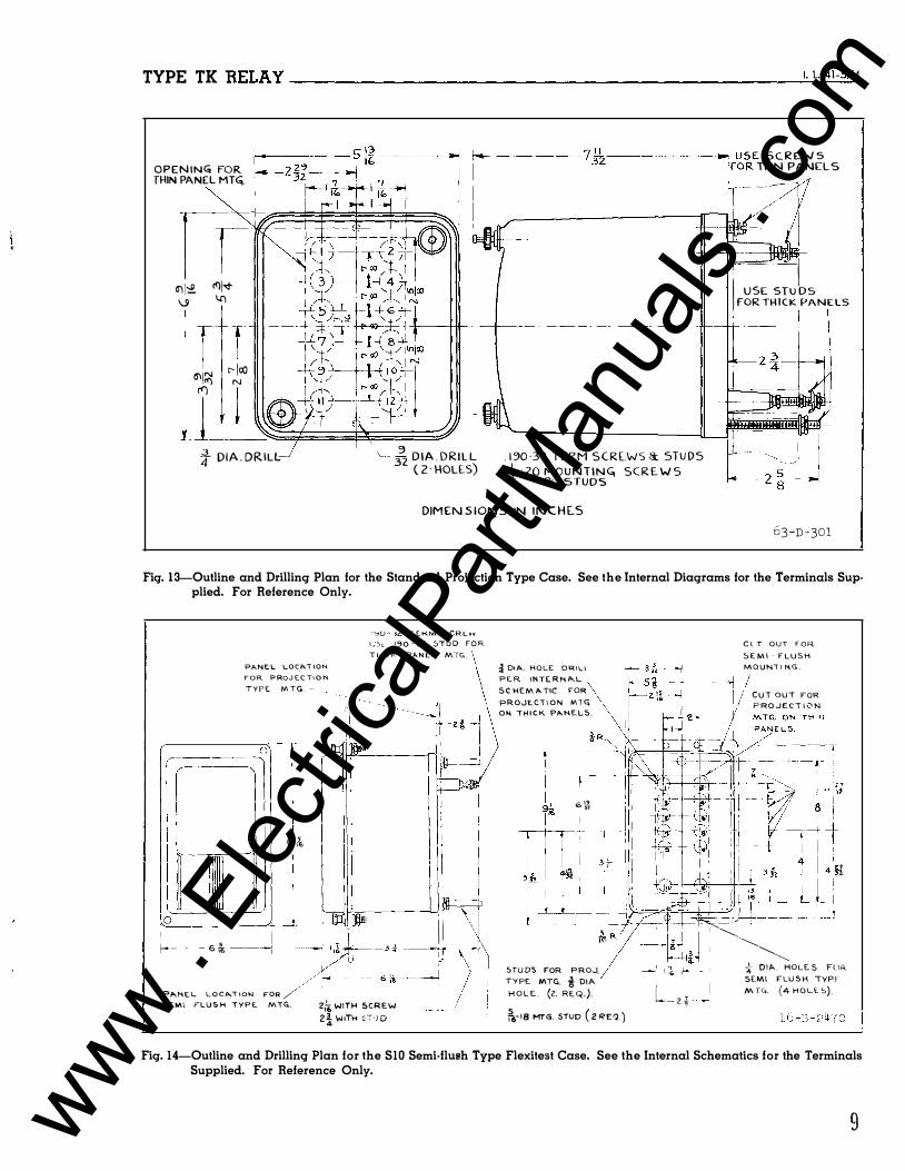
TYPE TK RELAY ------------------------------------------------��·�L�41�-5�74
OPEN IN<O FOR THIN PANEL MTG;.
a) 1':£ (!)['<!' \.9 I.()
I f I 6'\jN c-- [«J
!1') N ('I')
1---���� ' � } DIA. DRILL_; '- - - D IA . DRILL 32 ( Z · HOLE.S)
- � USE SCREWS (OR THIN PANELS
� --- ---------------------;r--,1 · /
. 1 �0 -32 TERM SCRE.WS &. STUDS -41 20 M O U N T I N G, SCR E W S
8::. STUDS
. -- --1 I USE. STU DS FOR TH I C K PANELS
I
DIMENSIONS IN I N C H LS
63-D- 301
Fig. 13-0utline and Drilling Plan for the Standard Projection Type Case. See the Internal Diagrams for the Terminals Supplied. For Reference Only.
r-·--
PANEL LOC_A.I \ON. FOR PROJEC T I O N T Y P � M T G . ·
0
''::>'U � 'L f t..KM. 5 C R t. vv t;)t. 190 - .32.. 3TUD FOR T h t C I-' PA.NEL M·rc;,
[�] I I I
I I
u ' � . 1 0&,
J 0
I ' I I I s i · --� � � �- . . -- � /r .. ::: • J \ PP.,NE L LOC .O..T I ON FOR / I SE.W\\ PLU S H i Y P E. MTG.. 2ff, WITH 5CR£W
2i W ITH �-T·J D
-i OIA. HOLE DRILl PE.R INTE.RN P...L
SCHEMATIC FOR PROJE.CTION MT(i
ON. \ H I C K P}!tr..N.E.L5.
l_ _
6 !..2 "
STUDS F'OR PROJ. TYPE MTCi. i DIA HOLE. (2. REQ.). ii&-18 MTG. STUD ( 2 REQ.)
L- z. i
C \. T OUT F OR S E M I · F L U S H M O U N\ I N. G .
C U T OUT FOR
P RO ..J E. C i i 0 N
T H N
'� ............ �� * Olf>-. HOLE S FOR. SEt.\1 FLU S H TYPF M TG. (4 HOLE.C>).
Fig. 14-0utline and Drilling Plan for the S10 Semi-flush Type Flexitest Case. See the Internal Schematics for the Terminals Supplied. For Reference Only.
9 www . El
ectric
alPar
tMan
uals
. com
TYPE TK RELAY-----------------------
far enough to just trip the contact finger .
The bronze pin pro jecting from each trip di sc
serves as its zero index , and should be op
posite the zero on the dial when the contact
finger trips . The trip screws are prevented
from turning by a locking wire spring which
passes through a slot in the inner end of the
trip s crew and is acces sible from the rear of
the trip di sc . It should be moved out of the
slot , and the trip screw should be screwed in
or out until the index pin is opposite the
zero on the dial when the contact finger is
released . Then the locking spring should
p laced in the slot of it s trip screw to
vent any accidental change in adjustment .
be
pre
The
trip dis cs shoul d release the c ontact fingers
when the trip screws are one scale division or
more from the center or lowest position .
Repeated tests have shown that the relay
wi ll make more than one million operations be
fore the striking and rubbing action of the
contact fingers on the ends of the latch arms
wears them sufficiently to require replac e
ment .
Contactor
All contac ts shoul d be periodically cleaned
with a fine file . S#l0021 10 file is recom
mended for thi s purpose . The use of abrasive
material for cleaning contacts is not recom
mended because of the danger of embedding
smal l particles in the fac e of the soft silver
and thus impairing the contact .
The stationary c ontacts should be adjusted
by bending so that both moving contacts make
simultaneously when they move in with the
armature , with about 1/16 inch follow . With
the relay de -energi zed, adjust the position of
the left -hand back c ontact spring , by means of
the adjusting s crew so that there will be a
gap of 1/64 inch or sl ightly more , between the
ends of the latch arms and the contact
fingers . Tighten the l ock nut securely . The
gap s between the c ontact fingers and the ends
of the latch arms should be approximately
equal . If the gaps are unequal , the c ontact
fingers probably have been bent . When the re
lay is de -energized and the front clutch mem
ber i s at the limit of its outward travel
there shoul d be a sl ight clearance between the
clutch spring and the washer at the front of
the clutch pinion . There shoul d also be
clearanc e between the clutch spring and the
dial plate .
The motor c ircuit contac t should have 1/16
inch to 3/32 inch foll ow when the right -hand
contact finger is against the latch arm . When
the motor circuit is open , there should be no
gap between the rear contact spring ( in whi ch
the flat contact is assemb l e d ) and its stop
plat e .
On relays provi ded with a sealing c ontac t ,
adjust the upper screw i n the bracket at the
front of the armature so that there
1/32 inch to 3/64 inch follow in the
wil l b e
seal -in
c ontact after it has closed . Tighten the l ock
nut securely . When the relay is de -energi zed
the seal -in contact shoul d have 1/32 inch to
3/64 inch gap .
RENEWAL PARTS
Repair work can be done most satisfac torily
at the factory . However , interchangeable
parts can be furnished to the cust omers who
are equipped for doing repair work . When
ordering part s , always give the comp lete name
p l ate data .
ENERGY REQUIREMENTS
10
The burden of the Type TK Relay at 1 1 5 volts , 60 cycles i s as follows :
Circuit
Motor
Contactor
Continuous Volt Rating
115
115
Watts
1 . 8
11 . 5
Reactive V. A .
l . 73
14 . 5
Volt -Amps .
2 . 5
18 . 5
P . F .
44° Lag
51 ° Lag
The burdens at the other 60 c ycle voltage ratings wil l be approximately the same as above .
I I
www . El
ectric
alPar
tMan
uals
. com

www . El
ectric
alPar
tMan
uals
. com

WESTINGHOUSE METER DIVISION
ELECTRIC •
CORPORATION NEWARK, N.J.
Printed in U. S. A. www . El
ectric
alPar
tMan
uals
. com
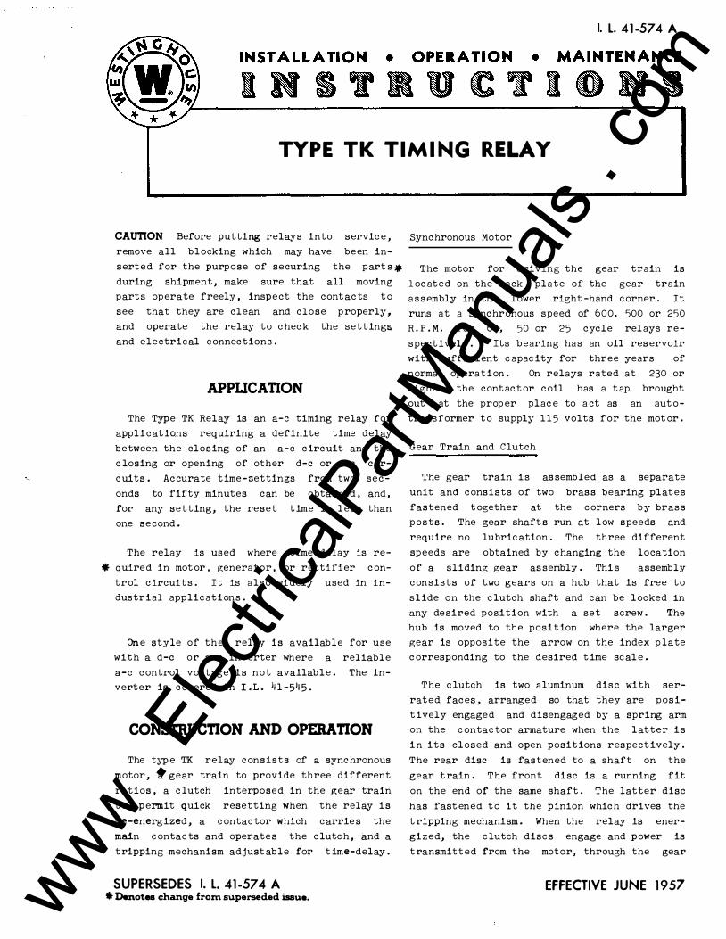
I. L. 41 -57 4 A
TYPE TK TIMING RELAY
CAUTION Before putting relays into service ,
remove all blocking which may have been in�
serted for the purpose of securing the part s �
during shipment, make sure that all moving
parts operate freely, inspect the contacts to
see that they are clean and close properly,
and operate the relay to check the setting�
and electrical connections.
APPUCATION
The Type TK Relay is an a�c timing relay for
applications requiring a definite time delay
between the closing of an a�c circuit and the
closing or opening of other d�c or a�c cir�
cuits. Accurate time-settings from two sec
onds to fifty minutes can be obtained, and,
for any setting, the reset time is less than
one second.
The relay is used where time delay is re
* quired in mot or , generator, or rectifier con
trol circuits . It is also widely used in in
dustrial applications.
One style of the relay is available for use
with a d-e or a-c inverter where a reliable
a-c control voltage is not available. The in
verter is covered in I . L . 41-545 .
CONSTRUCTION AND OPERATION
The type TK relay consists of a synchronous
motor, a gear train to provide three different
ratios , a clutch interposed in the gear train
t o permit quick resetting when the relay is
de-energized, a contactor which carrie s the
main contacts and operates the clutch, and a
tripping mechanism adjustable for t ime-delay .
SUPERSEDES I. L. 41-574 A * Denotes change from superseded issue.
Synchronous Motor
The motor for driving the gear train is
l ocated on the back plate of the gear train
a s s embly in the lower right -hand corner. It
runs at a synchronous speed of 600, 500 or 250
R.P.M. for 60, 50 or 25 cycle relays re
spectively. Its bearing has an oil res ervoir
with sufficient capacity for three years of
normal operation . On relays rated at 230 or
higher , the contact or coil has a tap brought
out at the prop er place to a ct as an aut o
transformer to supply 1 1 5 volts for the mot or.
Gear Train and Clutch
The gear train is as sembled as a separate
unit and consists of two bras s bearing plates
fastened together at the corners by brass
posts. The gear shaft s run at low speeds and
require no lubrication. The three different
speeds are obtained by changing the location
of a sliding gear as sembly. Thi s assembly
consists of t.wo gears on a hub that is free to
slide on the clutch shaft and can be locked in
any desired position with a set screw. The
hub is moved to the position where the larger
gear is opposite the arrow on the index p late
corresponding to the desired t ime scal e.
The clutch is two aluminum disc with ser
rated faces , arranged so that they are posi
t ively engaged and disengaged by a spring arm
on the contactor armature when the latter is
in its closed and open positions respectively.
The rear disc is fastened to a shaft on the
gear train. The front disc is a running fit
on the end of the same shaft. The latter disc
has fast ened to it the pinion which drives the
t ripping mechanism. When the relay is ener
gized, the clutch discs engage and power is
transmitted from the motor, through the gear
EFFECTIVE JUNE 1957 www . El
ectric
alPar
tMan
uals
. com
TYPE TK RELAY-----------------------
train , to the tripping mechani sm . When the
relay is de -energized, the c lutch di scs are
separated by the opening of the contac tor arm
ature .
Contactor
The c ont actor is a clapper type element
with a E shaped magnetic frame with a sole
noid coil on the center leg . The moving arma
ture is hinged at the b ottom of the magnetic
frame , and held open by a spring bel ow the
hinge . A spring arm is fastened to the top
c enter of the armature , and its outer end
presses against the front hal f of the clutch
when the cont actor coil is energized . The
position of this arm i s controlled by an ad
justing screw on a bracket fastened to the
front of the armature .
Two contact fingers are pivoted at the lower
end of the armature and each is free to move
independently of the armature against a spiral
spring . Silver c ontacts are fastened near the
top ends of the fingers . The stati onary con
tact arms have silver c ontact surfaces on the
outer ends , and are fastened to terminal posts
in the base . The make stationary contacts are
mounte d on l eaf springs with rigid back-up
arms to limit the deflection . Thi s c onstruc
tion in which both moving and stationary c on
tact arms deflect slightly, when contact is
made , minimizes the possibility of the con
tacts opening momentarily under severe shock .
The break stationary contact arms are leaf
springs with rigid supporting arms to prevent
overtravel .
The motion of the armature causes the clutch
discs to engage but will not close the con
tacts until the trip mechanism lat ches are re
leased . When these latches are released and
if the armature i s still closed the contact
arms move to the op erated position by the
action of the springs connecting the c ontact
arms to the armature .
Some styl es of the Type TK Relay are pro
vided with a seal ing contact to seal -in the
contactor coil until the c ircuit is opened by
an external contact or switch ( such as a push
button ) . The sealing contact is operated by
2
an adjustable Micarta button extending from
the same armature bracket which carries the
adjust ing screw for the clutch operating arm .
Thi s button closes a make cont act mounted on
top of the magnetic yoke of the c ontac tor .
Trip Mechanism
The trip mechanism i s carried on a shaft
thru the top of the gear train as sembly . A
large gear , a circular s cale and two adjust
ab le trip di scs are attached to thi s shaft .
The large gear meshes with the pinion on the
front clut ch di sc . The trip di scs each have a
smal l bronze index pin pro jecting approxi
mat ely 1/32 " from its edge . A hexagon headed
trip screw in each di sc operates one of the
two latch arms which in turn releases the
moving contact arms to operate the c ontact s .
The latch 8rms are mounted between bracket
arms extending from the gear train front
plate . The arrangement is such that the inner
trip di sc operates only the left hand latch,
while the outer trip disc operates. b oth latch
arms . The moving
only if the armature
c ontact arms can 0perate
is closed . The trip me-
chanism shaft resets by the action of a spring
fastened to the shaft and the gear train as
sembly plat e . The mechanism is adjusted so
that the index pins are opposite the zero on
the scale plate when the trip s crews in the
discs have reached a point where they just
ra i s e the Micarta latch arm surr i c i ently t o
release the c ont a c t arms , the trip discs being
rotated manual ly for thi s check while hol ding
the shaft against its stop .
CHARACTERISTICS
In the 50 and 60 cycle relays the maximum
time settings avail able for the three gear
positions are 30 seconds , 5 minutes , and 50
minutes . The smal lest sub -division i s 1 sec
ond on the 30 second scal e , 0 . 1 minute on the
5 minute s cale , and 1 minute on the 50 minute
s cale .
In the 25 cycle relays the maximum time
sett ing available for the three gear positions
are l , lO , and 100 minutes . The smallest sub
divi sion i s 2 seconds on the 1 minute scal e ,
0 . 2 minute on the 10 minute scale , 2 minut es
on the 1 00 minute scale .
www . El
ectric
alPar
tMan
uals
. com
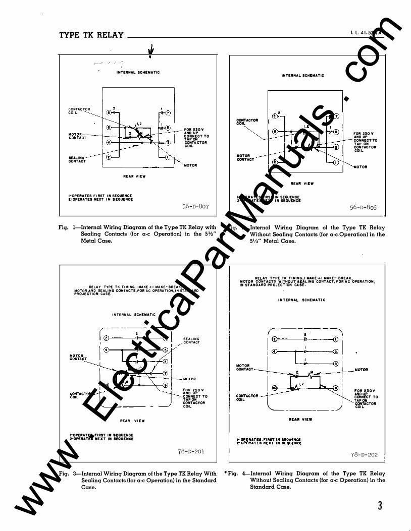
TYPE TK RELAY
GONTACTOR COIL
SEALING CONTACT
.. ----'
INTERNAL SCHEMATIC
REAli VIEW
I-OPERATES F I RST I N SEQUENCE z-OPERATES NEXT I N S EQUENCE
FOR no.v AND UP CONNECT TO TAP ON CONTACTOII cOIL
MOTOR
56-D-807
Fig. !-Internal Wiring Diagram of the Type TK Relay with Sealing Contacts (for a-c Operation) in the Slf2" Metal Case.
RELAY TYPE TK TIMING, I MAKE + I MAKE- BREAK, ��J��C��gN
s�:�IENG CONTACTS, FOR AC OPERATION, IN STANDARD
INTERNAL SCHEMATIC
REAR VI EW
!•OPERATES P'IRST Ill lt:QUENCE 2"0PERATt:l NEXT IN St:QUt:NCt:
S E ALING CONTACT
��� 5�0 v CONNECT TO TAP ON CONTACTOII COIL
78-D-201
Fig. 3-Internal Wiring Diagram of the Type TK Relay With Sealing Contacts (for a-c Operation) in the Standard Case.
I. l. 41-574 A
CONTACTOR COIL
MOTOR CONTACT
INTERNAL SCHEMATIC
REAR VIEW
I-OPERATES FIRST IN SEQUENCE 2-0PERATES NEXT I N SEQUENCE
FOil 230 V AND UP CONNECT TO TAP ON CONTACT OR cOI L
MOTOR
56-D-806
Fig. 2-Internal Wiring Diagram of the Type TK Relay Without Sealing Contacts (for a-c. Operation) in the S1/2" Metal Case.
RELAY TYPE TK T IMING, I MAKE+I MAKE- BREAK, :o��:
Ng���A�;gJ�ciWJ'rf';::��.LING cONTACT, FOR Ac OPERATION,
MOTOR CONTACT
I NTERNAL SCHEMATI c
r- - - - -t . - - � I® '�' 0 '1 i ® 1 : ®
l�o�� I
L _ _
I - �
RIEAR VIEW
P'OR 230V rdl,)'lcT TO TAP ON CONTACTOR COI L
78-D-202
* Fig. 4-lnternal Wiring Diagram of the Type TK Relay Without Sealing Contacts (for a-c Operation) in the Standard Case.
3 www . El
ectric
alPar
tMan
uals
. com
TYPE TK RELAY ______________ �----------------------------�
The re set time for maximum travel i s less
than one second . Since the clutch is disengages to reset , the reset t ime is independent
of the position of the sliding gear as sembly .
The motor may require one or two seconds to
reach synchronous speed after the relay is en
ergized and it s . average speed during this ac
celerating period wi ll be something less than
synchronous speed . The time scale s on the
dial make no provision for the effect the ac
celerating p eriod has upon the total operating
time , as thi s is not noticeable on the inter-
tripping disc mechanism counter-clockwise and
allow to reset to make sure that it returns to
zero positively . Remove the cover strip at
the top of the gear ca se . This can be readily
done by pulling a side one end of the strip
which covers the sides and bottom . This strip
i s held against the top corner posts by a
spring . When the bent -over end is clear of
the top strip , the strip can be lifted off ,
exposing the sliding gear as sembly and the
gear position index plate . With the large
gear on clutch shaft set opposite the 30-
second mark on index plate, rotate this gear mediate or slow speed settings . When the slowly in order to check for apparent friction gears are in the high speed position, it will in gear train . be more accurate to use a scale setting ap -
proximately one second less than the desired The relays shoul d be mounted on switchboard
time setting . The motor will operate at 1 0% panels or their equivalent in a location free
above or 1 5% under rated voltage . from dirt , moi sture , excess ive vibration and
The two sets of main contacts can be ad
justed to operate either simultaneously or s e
�uentially . The left hand s e t i s singl e pole
double throw (make & break ) and the right hand
set is s ingle pole single throw (make ) . The
right hand contact arm also op erates the inde
pendent break motor circuit contact . The make
contacts wi ll carry 12 amp eres cont inuously
and 20 amperes for l minute . The break con
tact has s omewhat less pres sure and will
carry about 2/3 this rating . The contacts
will open 2 amperes at 1 25 volts d-e ; or a
non-inductive current of 20 amperes at 115
volts a-c or 1 5 ampere s at 230 volts a-c .
A make sealing contact is supplied on some
relays . When supp lied it is connected as
shown in figures l , 3 and 6 to 9 and wil l keep
the relay
opened by a
relay .
energized until the circuit is
switch or contact external to the
INSTALLATION
Inspect relay for any damage that might have
occured in shipment . When removing the
blocking from the contactor armature , make
sure that the armature ha s not shifted off its
bearings . The armature blocking strips may be
left in the relay, with the short slotted ends
turned upward, for use in case of pos sible
future shipment of the relay . Rotate the
4
heat . Mount the relay vertical ly by means of
the two mounting studs for the standard cases
and the type FT projection case or by means of
the four mount ing holes on the flange for the
semi -flush type FT case . Either of the studs
or the mounting screws may be utilized for
grounding the relay . The electrical con
nections may be made direct to the terminals
by means of screws for steel panel mounting or
to terminal studs furnished with the relay for
ebony-asbestos or slate panel moantlng . The
terminal studs may be easily removed or in
serted by locking two nuts on the studs and
then turning the proper nut with a wrench .
Any appreciable variation from a level posi
tion will affect the operating characteristics
of the relay .
The internal and schematic external wiring
diagrams are shown in figures l thru 11 . The
operation of the d-e to a-c inverter is
covered in a separate instruction leaflet .
SEmNGS
The type TK Relay i s set for the desired
operating time by two adjustment s :
l . Remove the cover strip at the top of the
gear train assembly and shift the gears to the
desired time scal e .
In order to minimize the mechanical shock
due to the quick reset , the time scale used
www . El
ectric
alPar
tMan
uals
. com
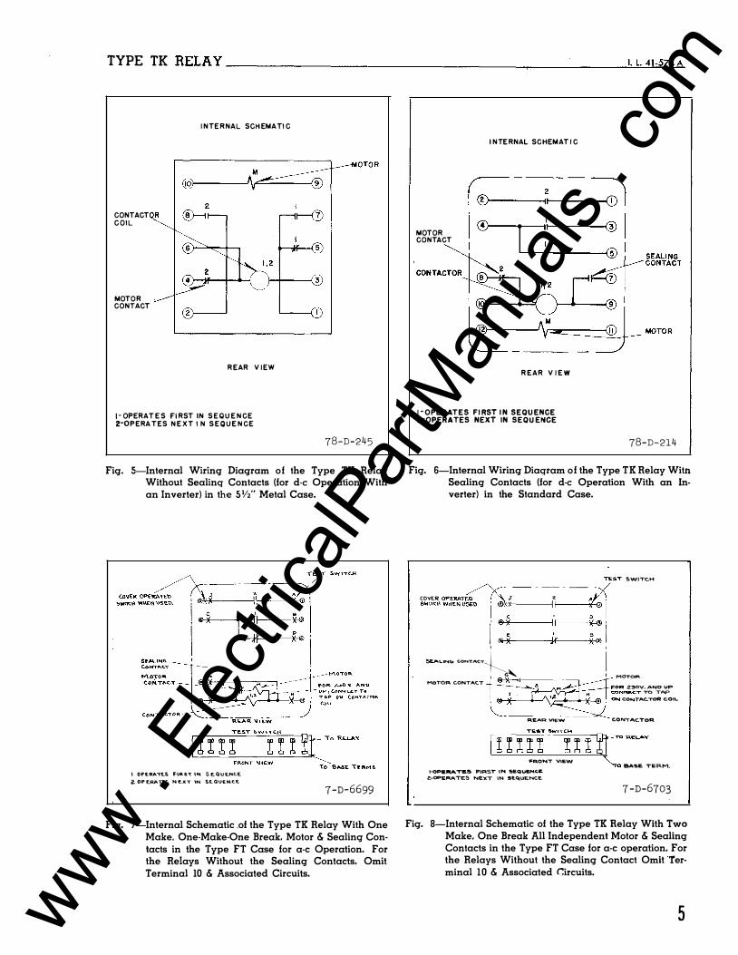
TYPE TK RELAY------------------------------------�----------��-�L�41�-5�7�4A
CONTACT COIL
MOTO R CONTACT
INTE RNAL SCH EMATIC
REAR VIEW
I - OPERAT E S FI RST IN S E Q U E N C E
2·0P E RATES NEXT I N S E Q U E N C E
78-D-245
Fig. 5-lnternal Wiring Diagram of the Type TK Relay Without Sealing Contacts (for d-e Operation With an Inverter) in the SV2" Metal Case.
\ Of"ERA.'Tt.S FUU.'T 11'11. S EQUE..N.CE 2. OP ERP.TU. N e..xT \N. SE-QUEM�E.
7-D-6699
Fig. 7-lnternal Schematic .of the Type TK Relay With One Make. One-Make-One Break. Motor & Sealing Contacts in the Type FT Case for a-c Operation. For the Relays Without the Sealing Contacts. Omit Terminal 10 & Associated Circuits.
MOTOR CONTACT
I NTE RNAL SCHEMAT I C
REAR V I E W
! · OPERATES FI RST I N SEQU ENCE i!•OPERATES NEXT IN SEQU ENCE
78-D-214
Fig. 6-Internal Wiring Diagram of the Type TK Relay Witn Sealing Contacts (for d-e Operation With an Inverter) in the Standard Case.
/'y-- - _ - _ _ iiTEST SWITCH
CO'IER: OPERA"T{�- .r � J' 2 A , SWITCH WHEN USEO i ®.;� I I X • I I, @: �·, �® 1. C!lX Jr )(® I I
SEAL\ ..... CONTACT� I MOTOR CONTAC.T I
&*--il �2. 1 : MOTOR. � M FOR 230V. ANO UP
1 ....... -� r H CONNI!.C.T TO TAP
' @ X \�II ' ON CONTACTOR COIL
"--- - - - - --REAR VlEW C.ONTACTOR
t:RONT VIEW
I·OPE�TB� PlRST" IN SE.QUE.NC.I!. 2.-0PERATES NEXT IN SEctUENCE
8A5E. TERM.
7-D-6703
Fig. 8-lnternal Schematic of the Type TK Relay With Two Make. One Break All Independent Motor & Sealing Contacts in the Type FT Case for a-c operation. For the Relays Without the Sealing Contact Omit Terminal 1 0 & Associated C:ircuits.
5 www . El
ectric
alPar
tMan
uals
. com

TYPE TK RELAY------------------------
C.ONTAC �Ill, COIL
SHAFT CONTACT C L 0 5 8 p WHEN CAMS R'RE. R e.�£."t,
SEALING CONTACT �---
TE!J>T SWITCH TO RELAY
I I ' FRONT '\IIEW "ro BA� TERM.
1- OPERATES FIRST IN SEQUENCE z.- OPE.RATE..!So SECOND IN SI!.GtUI!.NC.a
7 -D-6704
Fig. 9-lnternal Schematic of the Type TK Relay With One Make, One Make-One Break, Motor & Sealing Contact With Shaft Contact to Prevent Energization Before Relay Has Reset, in the Type FT Case for a-c Operation.
should be the longest of the three
permit the relay to be desired operating time . following paragraph ) .
set for the
(See the
which will
shortest
third
2 . Then loosen the thumb nut locking the
two trip di s c s to the trip mechani sm shaft ,
and rotate them until each index pin i s op -
posite the de sired scal e marking .
tighten the thumb nut .
Securely
The di sc nearest the scale plate will trip
the left finger only; the di sc that is neare st
the front will trip both contact fingers . To
set the contact fingers for sequential opera
tion the left finger must trip firs t , as the
motor is in series with the back c ontacts on
the right -hand side . When thi s finger is
tripped, it op ens the motor circuit .
In making these settings the trip di sc
should not be rotated so that the trip pins
are holding the Mi carta arms part way up .
Under thi s c ondition it is pos sible for the
moving contacts to bounc e under these arms and
close the front contacts instantaneously when
the relay is energized . The minimum sett ings
obtainable without partially raising the latch
arm are approximatel�r l -l/2 division on the 3 0
6
MOTOR
CONTACT
1- OPERATES FIRST IN SE.QUE ... CE
Z.-OPER.ATE.S NE.XT IN SEQ.UEf'\K.I!.
TO RE.L.AV
TO BASE TE.RM.
7 -D-6705
Fig. 10-Internal Schematic of the Type TK Relay With One Make. One Make-One Break, and Motor Contacts in the Type FT Case for d-e Operation With an. Inverter.
second scale , and c orre sponding point s on the
other scales .
In some applications it may be desired to
have the left -hand contact operate instantan
eously, as soon as the rel ay is energi zed, and
have time delay on the right -hand c ontact
only . This can be done by setting the dis c
nearest the s cal e p late so that the l eft -hand
latch arm is rai sed above the end of the con
tact finger when the trip di s c s are reset . If
any time -delay i s desired, however , the mini
mum sett ing obtainable without the pos sibility
of erratic operation i s the point at which the
trip disc begins to raise the latch arm .
ADJUSTMENTS AND MAINTENANCE
The proper adjustment s to insure correct
operat ion of thi s relay have been made at the
fact ory and should not be disturbed after re
ceipt by the customer . If the adjustments
have been changed, the relay taken apart for
repairs , or if it i s desired to check the ad
justments at regular maintenance periods , in
struct ions below shoul d be followed .
Synchronous Motor
The motor bearing contains a supp ly of
' I
www . El
ectric
alPar
tMan
uals
. com
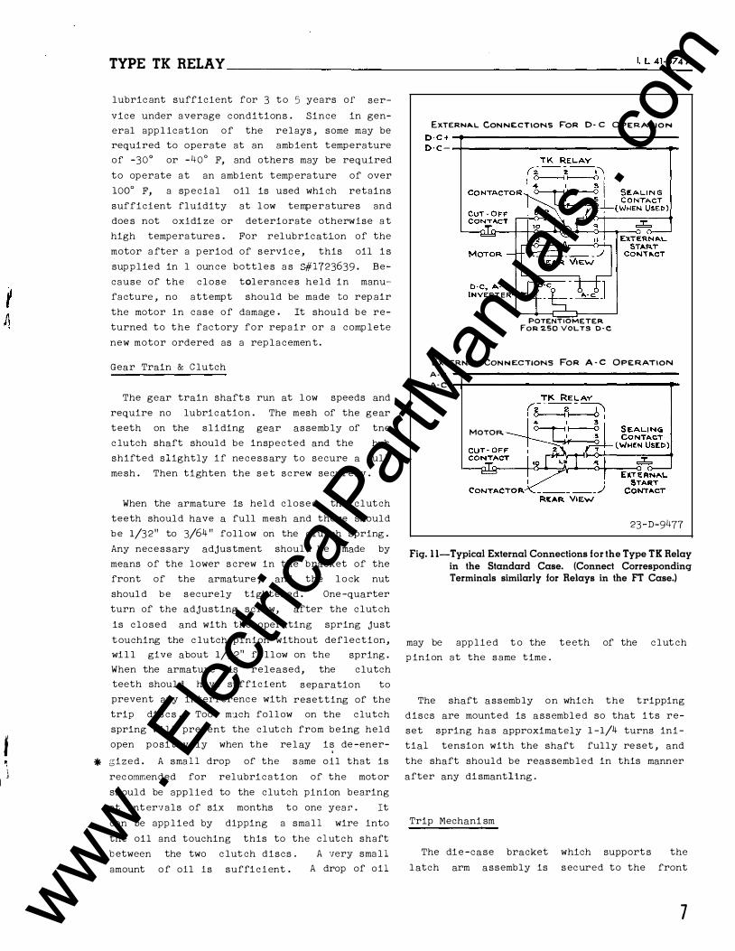
f 1
� '
TYPE TK RELAY ________________________________________________ r._t_4_1 -5_7 __ 4 A
lubric ant sufficient for 3 to 5 years of ser-
vice under average conditions . Since in gen
eral app l ication of the relays , some may be
required to operate at an amb ient temperature
of -30° or -40° F, and others may be required
to operate at an ambient temp erature of over
100° F, a sp ecial oil is used whi ch retains
sufficient fluidity at l ow temperatures and
doe s not oxidi ze or deteriorate otherwise a t
high temperatures . For relubrication of the
motor a fter a p eriod of servic e , this oil i s
supplied in l ounce bottles a s 8#1723639 - Be
cause of the close tolerances held in manu
facture , no attempt should be made to rep air
the motor in case of damage . It shoul d be re
turned to the factory for repair or a comp lete
new motor ordered as a replacemen t .
Gear Train & Clutch
The gear train shaft s run at l ow speeds and
require no lubric ation . The mesh of the gear
teeth on the sliding gear assemb ly of tne
c lutch shaft should be inspected and the hue
shifted slightly if necessary to secure a ful l
mesh . Then tighten the s e t screw securely .
When the armature is hel d closed, the clutch
teeth should have a full mesh and there should
be 1/32" to 3/64 " foll ow on the clut ch spring .
Any necessary adjustment shoul d be made by
means of the lower s crew in the bracket of the
front of the armature , and the l o ck nut
shoul d be securely tightened . One -quarter
turn of the adjusting screw, after the clutch
is closed and with the operating spring just
EXTERN,6o.L CONNE:CTIONS FoR 0- C OPERATION
0-C+-t-----------------------------------D · c - -+------------------------------�
POTENTIOMETER FoR 2.50 VOLTS D · C
ExTERNAL CoNN E:CTIONS FoR A - C OPE:RATION
A- C A- C 4------------------------.....
MOTOR.
23-D-9477
Fig. 1 1-Typical External Connections for the Type TK Relay in the Standard Case. (Connect Corresponding Terminals similarly for Relays in the FT Case.)
touching the c lutch pinion without deflection, may be applied t o the teeth of the clut ch wil l give about 1/32" follow on the spring . p inion at the same time . When the armature is released, the clutch
teeth shoul d have sufficient
prevent any interference with
trip dis c s . Too m�ch follow
separation to
resetting of the
on the clutch
spring wil l prevent the clutch from being held
open positively when the rel ay is de -ener-
* gized . A sma l l drop of the same oil that is
rec ommended for relubrication of the mot or
should be applied to the clutch pinion bearing
at int ervals of six months to one year . It
can be app lied by dipping a sma l l wire into
the oil and touching this to the clutch shaft
b etween the two c lut ch discs . A very sma l l
amount o f oil is sufficient . A drop of oil
The shaft assembly on which the tripping
discs are mounted is assembled so that its re
set spring has approximately 1 -1/4 turns ini
tial tension with the shaft fully re set , and
the shaft should be reas sembled in this manner
after any di smantling .
Trip Mechani sm
The die -case bracket which support s the
l atch arm assembly is secured to the front
7 www . El
ectric
alPar
tMan
uals
. com
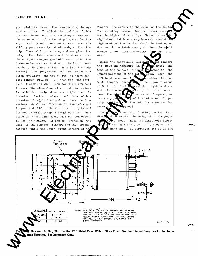
TYPE TK RELAY----------------------------------------------
gear plate by means of screws p as sing through
slotted holes . To adjust the position of this
bracket , loosen both the mounting screws and
the screw which holds the stop bracket for the
right hand ( front view ) latch arm . Move the
sliding gear as sembly out of me sh, so that the
trip disc s will not rotat e , and energize the
relay . The latch arms should be down so that
the contact fingers are hel d out . Shift the
die-case bracket so that with the latch arms
touching the aluminum trip dis c s ( not the trip
screws ) , the projection of the end of the
latch arm above the t op of its adjacent con
t act finger will be . 075 inch for the l eft
hand finger and . 070 inch for the right -hand
finger . The dimensions given apply to relays
in which the trip discs are 1 -1/8 inch in
diameter . Earlier relays used discs with a
diameter of 1-3/16 inch and on these the dim
ensions shoul d be . 010 inch for the left -hand
finger and . 1 20 inch for the right -hand
finger . A small strip of metal with the ends
filed to these dimensions wil l be convenient
to use as a gauge . It can be rested on the
ends of the contact fingers and the bracket
shifted until the upper front corners of the
fingers are even with the ends of the gauge .
The mounting screws for the bracket shoul d
then be tightened securely . The screw for the
right -hand l atch arm stop b racket shoul d be
tightened and the bracket should be bent up or
down until the latch arms just clear the small
bronze index pins projecting from the trip
disc .
Raise the right -hand l atch with the fingers
and move the armature in by hand until the
tips of the contact fingers are opposite the
lowest p ortions of the lat ch arms . When the
l eft -hand latch arm i s just touching its con
tact finger, there shoul d be a gap of about
. 01 0 11 to . 01 5 inch between the right -hand arm
and its contact finger . ( This relation be
tween the latches and the contact fingers pre
vents any possibility of the l eft-hand finger
tripping first when the trip disc s are set for
s imultaneous tripping ) .
Loosen the thumb nut locking the two trip
discs and energize the relay with the gears
still out of mesh . Hold the final gear firmly
against its back stop , and rotate each trip
disc by hand until it depr·esses its latch arm
� DRI LL 32(2 HOLES) \ M DRIL L
(AS REQUIRED)
NO, OF TERMINALS 8 OR LESS
.9 1 0
DRILL HOLES I TO 8
I TO .9 I TO 10
/
NOT E : FOR y�•OR 31!: ME.TAL SW B DS USE SCREWS FOR MTG. RELAY AND FOR. TE-RM I NAL CON N S . FOR '/4aTO I "'· SWE)DS USE. STUDS FOR MTG. RELAY AN D SCREWS FOR TERMI NAL CONNS • FOR . ALL OTHER SWBDS USE STUDS FOR OOTH PURPOSES.
56-D-815
Fig. 12-0utline and Drilling Plan for the SYz" Metal Case With a Glass Front. See the Internal Diagrams for the Term· inals Supplied. For Reference Only.
8 www . El
ectric
alPar
tMan
uals
. com
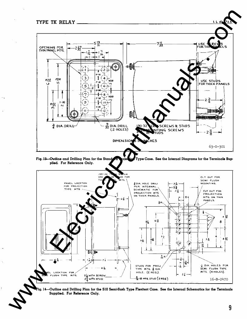
. \
TYPE TK RELAY----------------------------------------------�t=L.=41�-s���A
\__ _{z D I A . DRILL ( 2· HOLES)
7�--------i1-f U S E. SC. R E: W S FOR THIN PANELS
�------
. ----1 l USE STU DS FOR TH IC K PANELS . I
-�-- - --- - --- - --- - �-�
. 1 �0 -32. TERM. SC REWS 1t. STU D S -41 · zo MOUNTIN� SCR E. W S
8:. STUDS
DIMEN S IONS IN INCHE.S 63-D-301
Fiq. 13--0uWne and Drilling Plan for the Standard Projection Type Case. See the Internal Diagrams for the Terminals Supplied. For Reference Only.
0
r---- 6 &
P,t..NC.L LOC.�T\ON
FOR PRO J E C T I O N
IO i\
PA.NEL L O C,O..T I O N FOR
SE."'I FLU S H TYPE. MTG.
.190 - J 2. TE.RM. S C R t. V'I
USE . 1�0 - 32. S T U D FOR THICK P A N E L MTG.
� D I A. HOLE DRILl PE.R INTERNAL
S C H E M ATIC FOR
PR.OJE. C T I O N MT".
ON THICK PANELS.
6 r! "
STUDS F"OR PROJ. , TYPE MTG. i D I A . L HOLE . (z: REQ.).
�-18 MTC!;. STUD ( 2 REQ.)
C l T OUT FOR
S E M I - F L U S H
MOUNT I N G .
CUT OUT FOR PROJ E C T I O N
* O I A . H O L E S FOR SEMI FLU SH TYPE MTG. (4 HOLES).
16-B-2470
Fig. 14-0utline and Drilling Plan for the SlO Semi-flush Type Flexitest Case. See the Internal Schematics for the Terminals Supplied. For Reference Only.
9 www . El
ectric
alPar
tMan
uals
. com
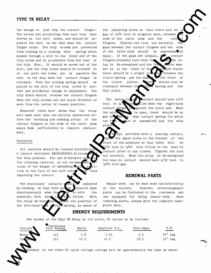
TYPE TK RELAY-----------------------
far enough to just trip the c ontact finger .
The bronze pin pro jecting from each trip di sc
serves as its zero index , and should be op
posite the zero on the dial when the contact
finger trips . The trip screws are prevented
from turning by a locking wire spring which
passes through a slot in the inner end of the
trip screw and is ac cessible from the rear of
the trip di sc . It should be moved out of the
slot , and the trip screw shou l d be screwed in
or out until the index pin is opposite the
zero on the dial when the contact finger is
released . Then the locking spring shoul d be
placed in the slot of its trip screw to pre
vent any accidental change in adjustment . The
trip discs shoul d release the contact fingers
when the trip screws are one scale division or
more from the center or lowest position .
Repeated tests have shown that the rel ay
wil l make more than one mill ion operations be
fore the striking and rubbing action of the
contact fingers on the ends of the latch arms
wears them sufficiently to require replace
ment .
Contact or
All contacts should be cl eaned periodically .
A c ontact burnisher S#l82A836H01 is recommended
for this purpose . The use of abrasive material
for cl eaning contacts is not rec ommended be
cause of the danger of embedding small part i
c l es in the face of the s oft s ilver and thus
impairing the contact .
The stationary contacts shoul d be adjusted
by b ending so that both moving contacts make
simultaneously when they move in with the
armature , with about 1/16 inch follow . With
the rel ay de -energized, adjust the position of
the left-hand back contact spring , by means of
the adjusting screw so that there will be a
gap of 1/64 inch or sl ightly more , between the
ends of the latch arms and the contact
fingers . Tighten the lock nut secure ly . The
gaps between the contact fingers and the ends
of the latch arms should be approximately
equal . If the gaps are unequal , the contact
fingers probably have been bent . When the re
lay is de -energized and the front clutch mem
ber i s at the limit of its outward travel
there should be a slight clearance between the
clutch spring and the washer at the front of
the clutch pinion . There should also be
clearance between the clutch spring and the
dial plate .
The motor c ircuit contact should have 1/16
inch to 3/32 inch follow when the right -hand
contact finger i s against the latch arm . When
the motor circuit i s open, there should be no
gap between the rear contact spring ( in whi ch
the flat contact i s assembled) and its stop
plat e .
On rel ays provided with a seal ing contac t ,
adjust the upp er screw i n the bracket a t the
front of the armature so that there will be
1/32 inch to 3/64 inch follow in the seal -in
contact after it has closed . Tighten the lock
nut securely . When the relay i s de-energized
the seal -in contact shoul d have 1/32 inch to 3/64 inch gap .
RENEWAL PARTS
Repair work can b e done most satisfactorily
at the factory . However , interchangeable
part s c an be furnished to the customers who
are equipped for doing repair work . When
ordering part s , always give the complete name
plate data .
ENERGY REQUIREMENTS
10
The burden of the Type TK Relay at 1 1 5 vol t s , 60 cycles is as follows :
Circuit
Motor
C ontactor
Continuous Volt Rating
115
115
Watts
1 . 8
11 . 5
Reactive V. A .
1 . 73
14 . 5
Volt-Amps .
2 . 5
1 8 . 5
P . F .
44° Lag
51 ° Lag
The burdens at the other 60 cycle vol tage ratings wil l be approximat ely the same as above .
www . El
ectric
alPar
tMan
uals
. com

www . El
ectric
alPar
tMan
uals
. com

WEST IN G HOUSE M E T ER DIVISION
ELE C T RI C •
· ..
C OR P ORAT I O N N EWARK, N.J .
Printed In U. S. A. www . El
ectric
alPar
tMan
uals
. com